WO2017212914A1 - 粒子検出装置及び粒子検出装置の制御方法 - Google Patents
粒子検出装置及び粒子検出装置の制御方法 Download PDFInfo
- Publication number
- WO2017212914A1 WO2017212914A1 PCT/JP2017/019242 JP2017019242W WO2017212914A1 WO 2017212914 A1 WO2017212914 A1 WO 2017212914A1 JP 2017019242 W JP2017019242 W JP 2017019242W WO 2017212914 A1 WO2017212914 A1 WO 2017212914A1
- Authority
- WO
- WIPO (PCT)
- Prior art keywords
- flow rate
- introduction
- fluid
- flow path
- chamber
- Prior art date
- Legal status (The legal status is an assumption and is not a legal conclusion. Google has not performed a legal analysis and makes no representation as to the accuracy of the status listed.)
- Ceased
Links
Images



Classifications
-
- G—PHYSICS
- G01—MEASURING; TESTING
- G01N—INVESTIGATING OR ANALYSING MATERIALS BY DETERMINING THEIR CHEMICAL OR PHYSICAL PROPERTIES
- G01N15/00—Investigating characteristics of particles; Investigating permeability, pore-volume or surface-area of porous materials
- G01N15/10—Investigating individual particles
- G01N15/14—Optical investigation techniques, e.g. flow cytometry
- G01N15/1404—Handling flow, e.g. hydrodynamic focusing
-
- G—PHYSICS
- G01—MEASURING; TESTING
- G01N—INVESTIGATING OR ANALYSING MATERIALS BY DETERMINING THEIR CHEMICAL OR PHYSICAL PROPERTIES
- G01N15/00—Investigating characteristics of particles; Investigating permeability, pore-volume or surface-area of porous materials
- G01N15/10—Investigating individual particles
- G01N15/14—Optical investigation techniques, e.g. flow cytometry
- G01N15/1456—Optical investigation techniques, e.g. flow cytometry without spatial resolution of the texture or inner structure of the particle, e.g. processing of pulse signals
- G01N15/1459—Optical investigation techniques, e.g. flow cytometry without spatial resolution of the texture or inner structure of the particle, e.g. processing of pulse signals the analysis being performed on a sample stream
-
- G—PHYSICS
- G01—MEASURING; TESTING
- G01N—INVESTIGATING OR ANALYSING MATERIALS BY DETERMINING THEIR CHEMICAL OR PHYSICAL PROPERTIES
- G01N15/00—Investigating characteristics of particles; Investigating permeability, pore-volume or surface-area of porous materials
- G01N15/01—Investigating characteristics of particles; Investigating permeability, pore-volume or surface-area of porous materials specially adapted for biological cells, e.g. blood cells
-
- G—PHYSICS
- G01—MEASURING; TESTING
- G01N—INVESTIGATING OR ANALYSING MATERIALS BY DETERMINING THEIR CHEMICAL OR PHYSICAL PROPERTIES
- G01N15/00—Investigating characteristics of particles; Investigating permeability, pore-volume or surface-area of porous materials
- G01N15/06—Investigating concentration of particle suspensions
- G01N15/075—Investigating concentration of particle suspensions by optical means
Definitions
- the present invention relates to an environment evaluation technique, and more particularly to a particle detection device and a control method for the particle detection device.
- a detection record of particles in the clean room may be attached to a product manufactured in the clean room as a reference material.
- the optical particle detection device for example, sucks a gas in a clean room and irradiates the sucked gas with excitation light. If the gas contains microbial particles or non-microbial fluorescent particles, the particles irradiated with the excitation light will emit fluorescence, so the number and size of the microbial particles and non-microbial fluorescent particles contained in the gas should be detected.
- the fluid is not limited to gas but also includes liquid.
- an object of the present invention is to provide a particle detection device and a method for controlling the particle detection device that can easily maintain a constant flow rate of a fluid to be inspected.
- a chamber a first introduction flow channel for introducing a fluid containing particles into the chamber, and (c) a fluid from which particles are removed in the chamber.
- a second introduction flow path for introduction (d) a detector for irradiating the fluid in the chamber with light to detect particles contained in the fluid; and (e) a discharge flow for discharging the fluid from the chamber.
- a flow path (f) an introduction flow meter for measuring the flow rate of the fluid flowing through the second introduction flow path, and (g) a predetermined flow rate of the fluid flowing through the first introduction flow path, and a flow rate measured by the introduction flow meter.
- a controller that controls the fluid with the total flow rate to flow through the discharge flow path.
- the particle detection apparatus further includes a suction device provided in the discharge channel for sucking the fluid in the chamber, and the control unit controls the suction device so that the total flow rate of fluid is sucked from the chamber. May be.
- the above-described particle detection device may further include a valve provided in the discharge channel, and the control unit may control the valve so that a total flow rate of fluid flows through the discharge channel.
- the particle detection apparatus may further include a discharge flow meter that measures the flow rate of the fluid flowing through the discharge flow path.
- the particle detection apparatus further includes a comparison unit that compares the difference between the flow rate measured by the introduction flow meter and the flow rate measured by the discharge flow meter and the predetermined flow rate of the fluid flowing through the first introduction flow path. May be.
- the particle detection apparatus may further include a correction unit that reduces the total flow rate flowing through the discharge flow path when the difference between the flow rate measured by the introduction flow meter and the flow rate measured by the discharge flow meter is larger than a predetermined flow rate.
- the particle detection device further includes a correction unit that increases the total flow rate flowing through the discharge flow path when the difference between the flow rate measured by the introduction flow meter and the flow rate measured by the discharge flow meter is smaller than a predetermined flow rate. May be.
- a method for controlling a particle detector is provided.
- the suction device provided in the discharge channel may be controlled so that the total flow rate of fluid is sucked from the chamber.
- a valve provided in the discharge channel may be controlled so that a total flow rate of fluid flows through the discharge channel.
- the control method of the particle detection apparatus may further include measuring the flow rate of the fluid flowing through the discharge flow path with a discharge flow meter.
- the method for controlling the particle detector further includes comparing the difference between the flow rate measured by the introduction flow meter and the flow rate measured by the discharge flow meter with a predetermined flow rate of the fluid flowing through the first introduction flow path. You may have.
- the particle detection device control method described above corrects to reduce the total flow rate flowing through the discharge flow channel. Furthermore, you may provide. In addition, when the difference between the flow rate measured by the introduction flow meter and the flow rate measured by the discharge flow meter is smaller than a predetermined flow rate, the particle detection device control method corrects the total flow rate flowing through the discharge flow path. It may be further provided.
- the present invention it is possible to provide a particle detection device that easily maintains a constant flow rate of a fluid to be inspected and a method for controlling the particle detection device.
- the particle detection apparatus includes a chamber 30, a first introduction flow path 225 for introducing a fluid containing particles into the chamber 30, and the chamber 30.
- the second introduction flow path 235 for introducing the fluid from which the particles have been removed, the light source 10 for irradiating the fluid in the chamber 30 to detect particles contained in the fluid, and the fluid being discharged from the chamber 30
- a discharge flow channel 260 for measuring the flow rate
- an introduction flow meter 245 for measuring the flow rate of the fluid flowing through the second introduction flow channel 235, a predetermined flow rate of the fluid flowing through the first introduction flow channel 225, and the introduction flow meter 245.
- the fluid includes gas and liquid.
- the fluid is a gas
- the chamber 30 is provided with an inlet nozzle 210 and an outlet nozzle 215.
- the inlet nozzle 210 is connected to the first introduction flow path 225.
- the tip of the inlet nozzle 210 and the tip of the outlet nozzle 215 are opposed to each other.
- An inlet passage 255 is connected to the inlet nozzle 210 via a first introduction passage 225.
- the gas flows from the inlet channel 255 through the first inlet channel 225 and flows into the chamber 30 from the tip of the inlet nozzle 210 and is discharged out of the chamber 30 from the tip of the outlet nozzle 215.
- Inlet nozzle 210 and outlet nozzle 215 define an air flow 40 through chamber 30.
- the light source 10 irradiates single-wavelength or broadband wavelength excitation light as the inspection light toward the airflow 40 that is the flow of the gas to be inspected.
- a light emitting diode (LED) and a laser can be used as the light source 10.
- the wavelength of the excitation light is, for example, 250 to 550 nm.
- the excitation light may be visible light or ultraviolet light. When the excitation light is visible light, the wavelength of the excitation light is, for example, in the range of 400 to 550 nm, for example, 405 nm. When the excitation light is ultraviolet light, the wavelength of the excitation light is, for example, in the range of 300 to 380 nm, for example, 340 nm. However, the wavelength of the excitation light is not limited to these.
- the excitation light is focused in the airflow 40, for example.
- a portion where the excitation light and the airflow 40 intersect may be referred to as a particle monitoring area (interrogation zone) 230.
- a second introduction flow path 235 that bypasses the inside of the chamber 30 is provided.
- the second introduction flow path 235 is provided with a filter 240, an introduction flow meter 245, a flow rate controller 250, and a filter 251.
- the filter 240 prevents particles contained in the gas flowing into the second introduction flow path 235 from entering the introduction flow meter 245.
- the introduction flow meter 245 measures the flow rate of the gas flowing through the second introduction flow path 235 and generates an electrical signal represented by voltage, current, or the like.
- a power source is connected to the introduction flow meter 245.
- the flow rate controller 250 such as an orifice adjusts the flow rate of the gas from the second introduction channel 235 toward the chamber 30.
- the filter 251 prevents particles that can be contained in the gas flowing through the introduction flow meter 245 and the flow controller 250 from entering the chamber 30.
- the second introduction channel 235 is connected to the chamber 30 at a position away from the particle monitoring area 230.
- the total flow rate of the gas flowing into the chamber 30 corresponds to the sum of the flow rate of the gas flowing in from the tip of the inlet nozzle 210 and the flow rate of the gas flowing in from the second introduction channel 235.
- the pressure caused by the gas flowing into the chamber 30 from the second introduction flow path 235 suppresses the air flow 40 between the tip of the inlet nozzle 210 and the tip of the outlet nozzle 215 from diffusing into the chamber 30. As a result, particles contained in the gas flowing into the chamber 30 from the tip of the inlet nozzle 210 are suppressed from diffusing into the chamber 30.
- a discharge passage 260 is connected to the outlet nozzle 215.
- a filter 265, a suction device 275, and a filter 280 are provided in the discharge flow path 260.
- a gas having a flow rate corresponding to the total flow rate of the gas flowing into the chamber 30 is discharged from the chamber 30 via the discharge flow path 260.
- the filter 265 suppresses particles from adhering to the suction device 275.
- the suction machine 275 supplies the outlet nozzle 215 with a sufficient negative pressure to draw the gas that has crossed the particle monitoring zone 230 in the chamber 30 into the discharge channel 260. Thereby, the pressure in the chamber 30 exceeds the pressure in the outlet nozzle 215. Note that the pressure in the inlet nozzle 210 is set to exceed the pressure in the chamber 30.
- a vacuum pump, a fan, a piston pump, a rotary pump, or the like can be used as the suction machine 275.
- Particles to be detected by the particle detection device include biological substances including microorganisms, cells, chemical substances, dust, dust, and dust such as dust.
- microorganisms include bacteria and fungi.
- bacteria include gram negative bacteria and gram positive bacteria.
- gram-negative bacteria include E. coli.
- Gram positive bacteria include Staphylococcus epidermidis, Bacillus subtilis, Micrococcus, and Corynebacterium.
- fungi include Aspergillus such as black mold.
- the microorganism is not limited to these.
- a light source driving power source 11 that supplies power to the light source 10 is connected to the light source 10.
- a power source control device 12 that controls the power supplied to the light source 10 is connected to the light source driving power source 11.
- the fluorescent microbial particles are irradiated with excitation light and emit fluorescence as reaction light.
- excitation light For example, riboflavin, flavin nucleotide (FMN), flavin adenine dinucleotide (FAD), nicotinamide adenine dinucleotide phosphate (NAD (P) H), pyridoxamine, pyridoxallin contained in fluorescent microbial particles Acid (pyridoxal-5′-phosphate), pyridoxine, tryptophan, tyrosine, phenylalanine, etc. fluoresce.
- FMN flavin nucleotide
- FAD flavin adenine dinucleotide
- NAD (P) H nicotinamide adenine dinucleotide phosphate
- pyridoxamine pyridoxallin contained in fluorescent microbial particles Acid (pyridoxal-5′-phosphate), pyridoxine, tryptophan, ty
- the fluorescent non-microbial particles are irradiated with excitation light and emit fluorescence as reaction light.
- a resin or the like that is a material of fluorescent non-microbial particles emits fluorescence.
- the non-fluorescent particles When the non-fluorescent particles are included in the airflow 40, the non-fluorescent particles irradiated with the excitation light do not emit fluorescence.
- the spectrum of light in the fluorescent band emitted by microbial and non-microbial particles varies depending on the type of microbial and non-microbial particles.
- the intensity of light in the fluorescence wavelength band emitted by microbial particles tends to be stronger on the longer wavelength side than the intensity of light in the fluorescence wavelength band emitted by non-microbial particles. Therefore, it is possible to determine whether a substance such as particles contained in the gas is a microorganism or a non-microbial particle based on the intensity of light in the fluorescence band detected at a plurality of wavelengths.
- Microbial particles, fluorescent non-microbial particles, and non-fluorescent particles have particle shapes that can cause Mie scattering when irradiated with light. Therefore, in the microbial particles and non-fluorescent particles irradiated with excitation light, scattered light is generated as reaction light due to Mie scattering.
- the wavelength of the scattered light by Mie scattering is the same as the wavelength of the excitation light.
- the intensity of the scattered light reflects the respective sizes of the microbial particles and the non-fluorescent particles. Therefore, it is possible to measure the size of the particles by measuring the intensity of the scattered light generated by the particles.
- the particle detector according to the first embodiment includes a fluorescence detector 2.
- the fluorescence detector 2 detects light in the fluorescence band emitted by microbial particles and the like.
- the fluorescence detector 2 is different from the first fluorescence wavelength band in the first light receiving element 20A that receives light in the first fluorescence wavelength band, and the second fluorescence on the shorter wavelength side than the first fluorescence wavelength band.
- a second light receiving element 20B that receives light in the wavelength band.
- a photodiode, a photomultiplier tube, or the like can be used as the first light receiving element 20A and the second light receiving element 20B. When receiving light, the light energy is converted into electric energy.
- the amplifier 21A for amplifying an analog signal generated by the first light receiving element 20A is connected to the first light receiving element 20A.
- An amplifier power supply 22A that supplies power to the amplifier 21A is connected to the amplifier 21A.
- An analog / digital (A / D) conversion circuit 23A is connected to the amplifier 21A.
- the A / D conversion circuit 23A converts the analog signal amplified by the amplifier 21A into a digital signal.
- a light intensity calculation device 24A for calculating the intensity of light received by the first light receiving element 20A is connected to the A / D conversion circuit 23A.
- the light intensity calculation device 24A calculates the light intensity based on the pulse waveform of the digital signal.
- a light intensity storage device 25A that stores the light intensity calculated by the light intensity calculation device 24A is connected to the light intensity calculation device 24A.
- the second light receiving element 20B is connected to an amplifier 21B that amplifies an analog signal generated by the second light receiving element 20B.
- An amplifier power supply 22B that supplies power to the amplifier 21B is connected to the amplifier 21B.
- An A / D conversion circuit 23B is connected to the amplifier 21B. The A / D conversion circuit 23B converts the analog signal amplified by the amplifier 21B into a digital signal.
- a light intensity calculation device 24B that calculates the intensity of light received by the second light receiving element 20B is connected to the A / D conversion circuit 23B. For example, the light intensity calculation device 24B calculates the light intensity based on the pulse waveform of the digital signal.
- a light intensity storage device 25B that stores the light intensity calculated by the light intensity calculation device 24B is connected to the light intensity calculation device 24B.
- the particle detector according to the first embodiment includes a scattered light detector 5.
- the scattered light detector 5 detects scattered light generated by microbial particles and non-microbial particles irradiated with the inspection light.
- the scattered light detector 5 includes a scattered light receiving element 50 that receives scattered light.
- a photodiode or the like can be used as the scattered light receiving element 50. When light is received, the light energy is converted into electric energy.
- the scattered light receiving element 50 is connected to an amplifier 51 that amplifies an analog signal generated by the scattered light receiving element 50.
- An amplifier power supply 52 that supplies power to the amplifier 51 is connected to the amplifier 51.
- an A / D conversion circuit 53 is connected to the amplifier 51. The A / D conversion circuit 53 converts the analog signal amplified by the amplifier 51 into a digital signal.
- the A / D conversion circuit 53 is connected to a light intensity calculation device 54 that calculates the intensity of scattered light received by the scattered light receiving element 50.
- the light intensity calculation device 54 calculates the light intensity based on the pulse waveform of the digital signal, for example.
- a light intensity storage device 55 that stores the intensity of scattered light calculated by the light intensity calculation device 54 is connected to the light intensity calculation device 54.
- the light source 10 irradiates the air flow 40 with excitation light
- the fluorescence detector 2 includes the intensity of the autofluorescence in the first wavelength band emitted by the particles included in the air flow 40 and the air flow 40.
- the intensity of the autofluorescence in the second wavelength band emitted by the particles is measured and stored in the light intensity storage devices 25A and 25B in time series.
- the scattered light detector 5 measures the scattered light generated by the particles contained in the airflow 40 and stores the light intensity of the scattered light in the light intensity storage device 55 in time series.
- the autofluorescence and scattered light of two wavelength bands detected at the same time can be regarded as originating from particles of the same individual.
- the particle detection device further includes a determination device 400.
- the determination apparatus 400 reads the light intensity value in the first fluorescence wavelength band and the light intensity value in the second fluorescence wavelength band from the light intensity storage devices 25A and 25B.
- the determination device 400 reads the intensity of scattered light from the light intensity storage device 55.
- the determination device 400 determines that the gas to be inspected contains non-fluorescent particles when the fluorescence detector 2 does not measure light in the fluorescence band and the scattered light detector 5 measures scattered light. Further, in the determination device 400, when the fluorescence detector 2 measures light in the fluorescence band and the scattered light detector 5 measures scattered light, the gas to be inspected contains fluorescent microbial particles or fluorescent non-microbial particles. Is determined.
- the determination apparatus 400 compares the intensity of light in the first fluorescence wavelength band with the intensity of light in the second fluorescence wavelength band.
- the determination device 400 includes the fluorescent microbial particles. It is determined that Further, the determination device 400 determines that the airflow 40 is a fluorescent non-biological particle when the intensity of light in the second fluorescence wavelength band on the short wavelength side is greater than the intensity of light in the first fluorescence wavelength band on the long wavelength side. Is determined to be included.
- the determination device 400 outputs the determination result from the output device 451, for example.
- the output device 451 a display, a speaker, a printer, and the like can be used.
- the control unit 301 illustrated in FIG. 1 is included in, for example, a central processing unit (CPU) 300.
- the control unit 301 receives the electrical signal generated by the introduction flow meter 245, and reversely calculates the flow rate of the gas flowing through the second introduction flow path 235 from the electrical signal.
- the CPU 300 is connected with a flow rate storage device 351.
- the flow rate storage device 351 flows through the first introduction flow path 225 and stores a predetermined value of the flow rate of the gas ejected from the inlet nozzle 210.
- the flow rate of the gas ejected from the inlet nozzle 210 is normally set to be constant in the particle detector.
- the flow rate storage device 351 stores a predetermined value of the flow rate set in this way.
- the control unit 301 includes a predetermined flow rate of the gas flowing through the first introduction flow channel 225 stored in the flow rate storage device 351, and a flow rate of the gas flowing through the second introduction flow channel 235 measured by the introduction flow meter 245. The total flow rate is calculated.
- the control unit 301 may store the calculated total flow rate in the flow rate storage device 351.
- the control unit 301 appropriately converts the calculated total flow rate into an electrical signal, and controls the suction device 275 so that the gas having the total flow rate is sucked from the chamber 30.
- the first introduction flow path 235 is not bypassed from the inlet flow path 255 and the first flow path 235 is bypassed.
- the ratio of the flow rate of the gas toward the introduction flow path 225 and the flow rate of the gas bypassing from the inlet flow path 255 to the second introduction flow path 235 varies.
- the suction device 275 sucks a constant value of the total flow rate of the normal flow rate of the gas flowing through the second introduction flow channel 235 and the predetermined flow rate of the gas flowing through the first introduction flow channel 225. If it continues, the flow volume of the gas injected from the inlet nozzle 210 will increase from a predetermined value. When the flow rate of the gas ejected from the inlet nozzle 210 is increased from a predetermined value, the pulse width of the electric signal generated by the light receiving element that receives the fluorescence or scattered light generated by the particles contained in the gas is reduced or the pulse peak is decreased. Sometimes.
- the inlet flow path 255 even when the flow rate of the gas flowing through the second introduction flow path 235 increases more than normal due to breakage of at least one of the filter 240, the flow controller 250, and the filter 251, the inlet flow path 255.
- the ratio of the flow rate of the gas that goes to the first introduction flow channel 225 without detouring from the first flow channel 235 to the flow rate of the gas that diverts from the inlet flow channel 255 to the second introduction flow channel 235 is ,fluctuate.
- the suction device 275 sucks a constant value of the total flow rate of the normal flow rate of the gas flowing through the second introduction flow channel 235 and the predetermined flow rate of the gas flowing through the first introduction flow channel 225. If it continues, the flow volume of the gas ejected from the inlet nozzle 210 will decrease from a predetermined value.
- the pulse width of the electric signal generated by the light receiving element that receives the fluorescence or scattered light generated by the particles contained in the gas is increased, or the pulse peak is increased.
- the flow rate of the gas toward the first introduction channel 225 without detouring from the inlet channel 255 to the second introduction channel 235 and Even if the ratio of the flow rate of the gas detouring from the inlet flow channel 255 to the second introduction flow channel 235 varies, the flow rate of the gas sucked by the suction device 275 changes according to the variation. Therefore, the flow rate of the gas ejected from the inlet nozzle 210 can be maintained at a predetermined value.
- the particle detection apparatus further includes a valve 285 provided in the discharge flow channel 260 and capable of adjusting the flow rate of the gas flowing through the discharge flow channel 260.
- the suction machine 275 sucks gas with a constant power, for example.
- the control unit 301 uses the predetermined flow rate of the gas flowing through the first introduction flow path 225 stored in the flow rate storage device 351 and the second flow rate measured by the introduction flow meter 245. The total flow rate of the gas flowing through the introduction flow path 235 and the total flow rate are appropriately converted into electrical signals, and the valve 285 is controlled so that the total flow rate of gas is sucked from the chamber 30.
- the particle detector according to the second embodiment can also maintain the flow rate of the gas ejected from the inlet nozzle 210 at a predetermined value.
- the particle detection apparatus further includes a discharge flow meter 295 provided in the discharge flow path 260 for measuring the flow rate of the gas flowing through the discharge flow path 260.
- the particle detection device has a difference between the flow rate measured by the introduction flow meter 245 and the flow rate measured by the discharge flow meter 295, and a predetermined flow rate of the fluid flowing through the first introduction flow path stored in the flow rate storage device 351.
- the particle detector is configured such that the difference between the flow rate measured by the introduction flow meter 245 and the flow rate measured by the discharge flow meter 295 is a predetermined amount of fluid flowing through the first introduction flow path stored in the flow rate storage device 351.
- the correction unit 303 further performs a correction to reduce the total flow rate calculated by the control unit 301.
- the correction unit 303 performs a correction to increase the total flow rate calculated by the control unit 301.
- the control unit 301 controls the flow rate of the gas flowing through the discharge channel 260 based on the corrected total flow rate.
- the flow rate of the gas flowing through the second introduction flow channel 235 measured by the introduction flow meter 245 is V b
- the predetermined flow rate of the gas flowing through the first introduction flow channel 225 stored in the flow rate storage device 351 is V s
- the flow rate of the gas flowing through the discharge flow path 260 measured by the discharge flow meter 295 is set as V t
- the comparison unit 302 introduces the flow rate V t measured by the discharge flow meter 295 and the introduction as shown in the following equation (1).
- the comparison unit 302 detects the gas ejected from the inlet nozzle 210. It is determined that the actual flow rate is within the normal range.
- the comparison unit 302 determines the actual flow rate of the gas ejected from the inlet nozzle 210. Is determined to be greater than the normal range.
- the correction unit 303 performs correction for reducing the total flow rate calculated by the control unit 301. As a result, the flow rate of the gas sucked by the suction machine 275 decreases, and the actual flow rate of the gas ejected from the inlet nozzle 210 falls within the normal range.
- the comparison unit 302 may perform the comparison continuously, or may perform arbitrary or predetermined intervals.
- the correcting unit 303 may perform the correction continuously, or may be performed at an arbitrary or predetermined interval. Further, the comparison by the comparison unit 302 and the correction by the correction unit 303 may be repeatedly performed an arbitrary number of times or a predetermined number of times.
- the formula used by the comparison unit 302 is not limited to the formula (1).
- the difference of may determine to or less than the threshold T h.
- comparison section 302 determines that the actual flow rate of the gas blown from the inlet nozzle 210 is not within the normal range.
Landscapes
- Chemical & Material Sciences (AREA)
- Dispersion Chemistry (AREA)
- Physics & Mathematics (AREA)
- Health & Medical Sciences (AREA)
- Life Sciences & Earth Sciences (AREA)
- Analytical Chemistry (AREA)
- Biochemistry (AREA)
- General Health & Medical Sciences (AREA)
- General Physics & Mathematics (AREA)
- Immunology (AREA)
- Pathology (AREA)
- Investigating, Analyzing Materials By Fluorescence Or Luminescence (AREA)
Abstract
チャンバ30と、チャンバ30内に粒子を含む流体を導入するための第1の導入流路225と、チャンバ30内に粒子が除去された流体を導入するための第2の導入流路235と、流体に含まれる粒子を検出するためにチャンバ30内の流体に光を照射する光源10と、チャンバ30から流体を排出するための排出流路260と、第2の導入流路235を流れる流体の流量を計測する導入流量計245と、第1の導入流路225を流れる流体の所定の流量と、導入流量計245が計測した第2の導入流路235を流れる流体の流量と、の合計流量の流体が排出流路260を流れるよう制御する制御部301と、を備える粒子検出装置。
Description
本発明は環境評価技術に関し、特に粒子検出装置及び粒子検出装置の制御方法に関する。
バイオクリーンルーム等のクリーンルームにおいては、粒子検出装置を用いて、飛散している微生物粒子や非微生物粒子が検出され、記録される。粒子の検出結果から、クリーンルームの空調機器の劣化具合を把握可能である。また、クリーンルームで製造された製品に、参考資料として、クリーンルーム内の粒子の検出記録が添付されることもある。光学式の粒子検出装置は、例えば、クリーンルーム中の気体を吸引し、吸引した気体に励起光を照射する。気体に微生物粒子や非微生物蛍光粒子が含まれていると、励起光を照射された粒子が蛍光を発するため、気体に含まれる微生物粒子や非微生物蛍光粒子の数や大きさ等を検出することが可能となる(例えば、特許文献1参照。)。また、クリーンルーム以外でも、流体中の粒子を正確に検出する技術が望まれている。ここで、流体は、気体に限られず、液体も含む。
粒子検出装置においては、励起光を照射される流体の流速、及び流速から算出される流量が、流体に含まれる粒子の検出精度に影響を与えうる。そのため、粒子検出装置における流体の流速に関する規格も存在する。そこで、本発明は、検査対象の流体の流量を一定に保ちやすい粒子検出装置及び粒子検出装置の制御方法を提供することを目的の一つとする。
本発明の態様によれば、(a)チャンバと、(b)チャンバ内に粒子を含む流体を導入するための第1の導入流路と、(c)チャンバ内に粒子が除去された流体を導入するための第2の導入流路と、(d)チャンバ内の流体に光を照射し、流体に含まれる粒子を検出する検出器と、(e)チャンバから流体を排出するための排出流路と、(f)第2の導入流路を流れる流体の流量を計測する導入流量計と、(g)第1の導入流路を流れる流体の所定の流量と、導入流量計が計測した流量と、の合計流量の流体が排出流路を流れるよう制御する制御部と、を備える、粒子検出装置が提供される。
上記の粒子検出装置が、排出流路に設けられた、チャンバ内の流体を吸引するための吸引機をさらに備え、制御部が、合計流量の流体がチャンバから吸引されるよう、吸引機を制御してもよい。
上記の粒子検出装置が、排出流路に設けられた弁をさらに備え、制御部が、合計流量の流体が排出流路を流れるよう、弁を制御してもよい。
上記の粒子検出装置が、排出流路を流れる流体の流量を計測する排出流量計をさらに備えていてもよい。
上記の粒子検出装置が、導入流量計が計測した流量と排出流量計が計測した流量の差と、第1の導入流路を流れる流体の所定の流量と、を比較する比較部をさらに備えていてもよい。
上記の粒子検出装置が、導入流量計が計測した流量と排出流量計が計測した流量の差が所定の流量より大きい場合、排出流路を流れる合計流量を減少させる補正部をさらに備えていてもよい。また、上記の粒子検出装置が、導入流量計が計測した流量と排出流量計が計測した流量の差が所定の流量より小さい場合、排出流路を流れる合計流量を増加させる補正部をさらに備えていてもよい。
また、本発明の態様によれば、(a)粒子検出装置のチャンバ内に第1の導入流路から粒子を含む流体を導入することと、(b)チャンバ内に第2の導入流路から粒子が除去された流体を導入することと、(c)チャンバから排出流路を用いて流体を排出することと、(d)第2の導入流路を流れる流体の流量を導入流量計で計測することと、(e)第1の導入流路を流れる流体の所定の流量と、導入流量計が計測した流量と、の合計流量の流体が排出流路を流れるよう制御することと、を備える、粒子検出装置の制御方法が提供される。
上記の粒子検出装置の制御方法における制御することにおいて、合計流量の流体がチャンバから吸引されるよう、排出流路に設けられた吸引機を制御してもよい。
上記の粒子検出装置の制御方法における制御することにおいて、合計流量の流体が排出流路を流れるよう、排出流路に設けられた弁を制御してもよい。
上記の粒子検出装置の制御方法が、排出流路を流れる流体の流量を排出流量計で計測することをさらに備えていてもよい。
上記の粒子検出装置の制御方法が、導入流量計が計測した流量と排出流量計が計測した流量の差と、第1の導入流路を流れる流体の所定の流量と、を比較することをさらに備えていてもよい。
上記の粒子検出装置の制御方法が、導入流量計が計測した流量と排出流量計が計測した流量の差が所定の流量より大きい場合、排出流路を流れる合計流量を減少させる補正をすることをさらに備えていてもよい。また、上記の粒子検出装置の制御方法が、導入流量計が計測した流量と排出流量計が計測した流量の差が所定の流量より小さい場合、排出流路を流れる合計流量を増加させる補正をすることをさらに備えていてもよい。
本発明によれば、検査対象の流体の流量を一定に保ちやすい粒子検出装置及び粒子検出装置の制御方法を提供可能である。
以下に本発明の実施の形態を説明する。以下の図面の記載において、同一又は類似の部分には同一又は類似の符号で表している。但し、図面は模式的なものである。したがって、具体的な寸法等は以下の説明を照らし合わせて判断するべきものである。また、図面相互間においても互いの寸法の関係や比率が異なる部分が含まれていることは勿論である。
(第1の実施の形態)
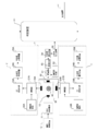
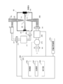
第1の実施の形態に係る粒子検出装置は、図1に示すように、チャンバ30と、チャンバ30内に粒子を含む流体を導入するための第1の導入流路225と、チャンバ30内に粒子が除去された流体を導入するための第2の導入流路235と、流体に含まれる粒子を検出するためにチャンバ30内の流体に光を照射する光源10と、チャンバ30から流体を排出するための排出流路260と、第2の導入流路235を流れる流体の流量を計測する導入流量計245と、第1の導入流路225を流れる流体の所定の流量と、導入流量計245が計測した第2の導入流路235を流れる流体の流量と、の合計流量の流体が排出流路260を流れるよう制御する制御部301と、を備える。流体とは、気体及び液体を含む。以下においては、流体が気体である例を説明する。
第1の実施の形態に係る粒子検出装置は、図1に示すように、チャンバ30と、チャンバ30内に粒子を含む流体を導入するための第1の導入流路225と、チャンバ30内に粒子が除去された流体を導入するための第2の導入流路235と、流体に含まれる粒子を検出するためにチャンバ30内の流体に光を照射する光源10と、チャンバ30から流体を排出するための排出流路260と、第2の導入流路235を流れる流体の流量を計測する導入流量計245と、第1の導入流路225を流れる流体の所定の流量と、導入流量計245が計測した第2の導入流路235を流れる流体の流量と、の合計流量の流体が排出流路260を流れるよう制御する制御部301と、を備える。流体とは、気体及び液体を含む。以下においては、流体が気体である例を説明する。
チャンバ30には、入口ノズル210及び出口ノズル215が設けられている。入口ノズル210は、第1の導入流路225に接続されている。入口ノズル210の先端と、出口ノズル215の先端と、は、対向している。入口ノズル210には、第1の導入流路225を介して、入口流路255が接続されている。入口流路255から第1の導入流路225を経て流れて、気体は、入口ノズル210の先端からチャンバ30内に流入し、出口ノズル215の先端からチャンバ30の外に排出される。入口ノズル210及び出口ノズル215は、チャンバ30内を通る気流40を画定する。
光源10は、検査対象の気体の流れである気流40に向けて、検査光として、単波長又は広帯域波長の励起光を照射する。光源10としては、例えば、発光ダイオード(LED)及びレーザが使用可能である。励起光の波長は、例えば250ないし550nmである。励起光は、可視光であっても、紫外光であってもよい。励起光が可視光である場合、励起光の波長は、例えば400ないし550nmの範囲内であり、例えば405nmである。励起光が紫外光である場合、励起光の波長は、例えば300ないし380nmの範囲内であり、例えば340nmである。ただし、励起光の波長は、これらに限定されない。
励起光は、例えば、気流40内において、焦点を結ぶ。励起光と、気流40と、が、交差する部分は、粒子監視域(インターロゲーションゾーン)230と呼ばれることもある。
入口ノズル210と出口ノズル215の間の粒子監視域230から粒子がチャンバ30内に拡散しないよう、入口流路255内の気体の一部を、第1の導入流路225及び入口ノズル210の先端を迂回してチャンバ30内に導く第2の導入流路235が設けられている。第2の導入流路235には、フィルタ240、導入流量計245、流量調節器250、及びフィルタ251が設けられている。
フィルタ240は、第2の導入流路235に流入した気体に含まれる粒子が、導入流量計245に進入することを抑制する。導入流量計245は、第2の導入流路235を流れる気体の流量を計測し、電圧や電流等で表される電気信号を発生する。導入流量計245には、電源が接続されている。オリフィス等の流量調節器250は、第2の導入流路235からチャンバ30に向かう気体の流量を調節する。フィルタ251は、導入流量計245及び流量調節器250を流れた気体に含まれうる粒子が、チャンバ30に進入することを抑制する。
入口流路255から第2の導入流路235に迂回せず、第1の導入流路225に向かう気体の流量と、入口流路255から第2の導入流路235に迂回する気体の流量と、の比は、正常であれば一定である。
第2の導入流路235は、粒子監視域230から離れた位置でチャンバ30に接続される。チャンバ30の内部に流入する気体の全流量は、入口ノズル210の先端から流入する気体の流量と、第2の導入流路235から流入する気体の流量と、の合計に相当する。
第2の導入流路235からチャンバ30に流入した気体による圧力は、入口ノズル210の先端と出口ノズル215の先端との間の気流40が、チャンバ30内に拡散することを抑制する。これにより、入口ノズル210の先端からチャンバ30内に流入した気体に含まれる粒子が、チャンバ30内に拡散することが抑制される。
第2の導入流路235からチャンバ30に流入した気体による圧力は、入口ノズル210の先端と出口ノズル215の先端との間の気流40が、チャンバ30内に拡散することを抑制する。これにより、入口ノズル210の先端からチャンバ30内に流入した気体に含まれる粒子が、チャンバ30内に拡散することが抑制される。
出口ノズル215には、排出流路260が接続されている。排出流路260には、フィルタ265、吸引機275、及びフィルタ280が設けられている。チャンバ30の内部に流入した気体の全流量に相当する流量の気体が、排出流路260を介して、チャンバ30から排出される。フィルタ265は、吸引機275に粒子が付着することを抑制する。吸引機275は、チャンバ30内の粒子監視域230を横切った気体を排出流路260に引き込むための十分な負圧を、出口ノズル215に供給する。これにより、チャンバ30内の圧力が、出口ノズル215内の圧力を超過する。なお、入口ノズル210内の圧力は、チャンバ30内の圧力を超過するように設定される。吸引機275としては、真空ポンプ、ファン、ピストンポンプ、及びロータリーポンプ等が使用可能である。
粒子検出装置が検出対象とする粒子は、微生物等を含む生体物質、細胞、化学物質、ごみ、ちり、及び埃等のダスト等を含む。微生物の例としては細菌及び真菌が含まれる。細菌の例としては、グラム陰性菌及びグラム陽性菌が挙げられる。グラム陰性菌の例としては、大腸菌が挙げられる。グラム陽性菌の例としては、表皮ブドウ球菌、枯草菌、マイクロコッカス、及びコリネバクテリウムが挙げられる。真菌の例としては、黒カビ等のアスペルギルスが挙げられる。ただし、微生物はこれらに限定されない。
図2に示すように、光源10には、光源10に電力を供給する光源駆動電源11が接続されている。光源駆動電源11には、光源10に供給される電力を制御する電源制御装置12が接続されている。
気流40に、蛍光性微生物粒子が含まれていると、蛍光性微生物粒子は励起光を照射されて、反応光として蛍光を発する。例えば、蛍光性微生物粒子に含まれるリボフラビン(riboflavin)、フラビンヌクレオチド(FMN)、フラビンアデニンジヌクレオチド(FAD)、ニコチンアミドアデニンジヌクレオチドリン酸(NAD(P)H)、ピリドキサミン(pyridoxamine)、ピリドキサールリン酸(pyridoxal-5’-phosphate)、ピリドキシン(pyridoxine)、トリプトファン(tryptophan)、チロシン(tyrosine)、及びフェニルアラニン(phenylalanine)等が、蛍光を発する。
気流40に、蛍光性非微生物粒子が含まれていると、蛍光性非微生物粒子は励起光を照射されて、反応光として蛍光を発する。例えば、蛍光性非微生物粒子の材料である樹脂等が、蛍光を発する。
気流40に非蛍光性粒子が含まれている場合、励起光を照射された非蛍光性粒子は蛍光を発しない。
微生物粒子及び非微生物粒子が発する蛍光帯域の光のスペクトルは、微生物粒子及び非微生物粒子の種類によって異なる。また、一般に、微生物粒子が発する蛍光波長帯域の光の強度は、非微生物粒子が発する蛍光波長帯域の光の強度よりも長波長側で強い傾向にある。そのため、複数の波長において検出した蛍光帯域の光の強度に基づいて、気体に含まれる粒子等の物質が、微生物であるか、あるいは非微生物粒子であるかを判定することが可能となる。
微生物粒子、蛍光性非微生物粒子、及び非蛍光性粒子は、光を照射されると、ミー散乱を生じうる粒子形状である。したがって、励起光を照射された微生物粒子及び非蛍光性粒子において、ミー散乱により、反応光として散乱光が生じる。ミー散乱による散乱光の波長は、励起光の波長と同じである。散乱光の強度は、微生物粒子及び非蛍光性粒子のそれぞれの大きさを反映している。したがって、粒子で生じた散乱光の強度を測定することにより、粒子の大きさを測定することが可能である。
第1の実施の形態に係る粒子検出装置は、蛍光検出器2を備える。蛍光検出器2は、微生物粒子等が発する蛍光帯域の光を検出する。蛍光検出器2は、第1の蛍光波長帯域の光を受光する第1の受光素子20Aと、第1の蛍光波長帯域とは異なり、第1の蛍光波長帯域より短波長側の第2の蛍光波長帯域の光を受光する第2の受光素子20Bと、を備える。第1の受光素子20A及び第2の受光素子20Bとしては、フォトダイオード及び光電子増倍管等が使用可能であり、光を受光すると、光エネルギーを電気エネルギーに変換する。
第1の受光素子20Aには、第1の受光素子20Aで生じたアナログ信号を増幅する増幅器21Aが接続されている。増幅器21Aには、増幅器21Aに電力を供給する増幅器電源22Aが接続されている。また、増幅器21Aには、アナログデジタル(A/D)変換回路23Aが接続されている。A/D変換回路23Aは、増幅器21Aで増幅されたアナログ信号をデジタル信号に変換する。
A/D変換回路23Aには、第1の受光素子20Aが受光した光の強度を算出する光強度算出装置24Aが接続されている。光強度算出装置24Aは、例えば、デジタル信号のパルス波形に基づいて、光の強度を算出する。光強度算出装置24Aには、光強度算出装置24Aが算出した光の強度を保存する光強度記憶装置25Aが接続されている。
第2の受光素子20Bには、第2の受光素子20Bで生じたアナログ信号を増幅する増幅器21Bが接続されている。増幅器21Bには、増幅器21Bに電力を供給する増幅器電源22Bが接続されている。また、増幅器21Bには、A/D変換回路23Bが接続されている。A/D変換回路23Bは、増幅器21Bで増幅されたアナログ信号をデジタル信号に変換する。
A/D変換回路23Bには、第2の受光素子20Bが受光した光の強度を算出する光強度算出装置24Bが接続されている。光強度算出装置24Bは、例えば、デジタル信号のパルス波形に基づいて、光の強度を算出する。光強度算出装置24Bには、光強度算出装置24Bが算出した光の強度を保存する光強度記憶装置25Bが接続されている。
第1の実施の形態に係る粒子検出装置は、散乱光検出器5を備える。散乱光検出器5は、検査光を照射された微生物粒子及び非微生物粒子で生じる散乱光を検出する。散乱光検出器5は、散乱光を受光する散乱光受光素子50を備える。散乱光受光素子50としては、フォトダイオード等が使用可能であり、光を受光すると、光エネルギーを電気エネルギーに変換する。
散乱光受光素子50には、散乱光受光素子50で生じたアナログ信号を増幅する増幅器51が接続されている。増幅器51には、増幅器51に電力を供給する増幅器電源52が接続されている。また、増幅器51には、A/D変換回路53が接続されている。A/D変換回路53は、増幅器51で増幅されたアナログ信号をデジタル信号に変換する。
A/D変換回路53には、散乱光受光素子50が受光した散乱光の強度を算出する光強度算出装置54が接続されている。光強度算出装置54は、例えば、デジタル信号のパルス波形に基づいて、光の強度を算出する。光強度算出装置54には、光強度算出装置54が算出した散乱光の強度を保存する光強度記憶装置55が接続されている。
気流40が流れると、光源10が気流40に励起光を照射し、蛍光検出器2が、気流40に含まれる粒子が発した第1の波長帯域の自家蛍光の強度と、気流40に含まれる粒子が発した第2の波長帯域の自家蛍光の強度と、を測定し、時系列的に光強度記憶装置25A、25Bに保存する。また、散乱光検出器5が、気流40に含まれる粒子で生じた散乱光を測定し、散乱光の光強度を時系列的に光強度記憶装置55に保存する。同時に検出された2つの波長帯域の自家蛍光と、散乱光と、は、同一個体の粒子由来とみなしうる。
第1の実施の形態に係る粒子検出装置は、判定装置400をさらに含む。判定装置400は、第1の蛍光波長帯域の光の強度の値と、第2の蛍光波長帯域の光の強度の値と、を光強度記憶装置25A、25Bから読み出す。また、判定装置400は、散乱光の強度を、光強度記憶装置55から読み出す。
判定装置400は、蛍光検出器2が蛍光帯域の光を測定せず、散乱光検出器5が散乱光を測定した場合、検査対象の気体が非蛍光性粒子を含むと判定する。また、判定装置400は、蛍光検出器2が蛍光帯域の光を測定し、散乱光検出器5が散乱光を測定した場合、検査対象の気体が蛍光性微生物粒子又は蛍光性非微生物粒子を含むと判定する。
さらに、判定装置400は、第1の蛍光波長帯域の光の強度と、第2の蛍光波長帯域の光の強度と、を比較する。判定装置400は、長波長側の第1の蛍光波長帯域の光の強度が、短波長側の第2の蛍光波長帯域の光の強度よりも大きい場合、気流40が蛍光性微生物粒子を含んでいると判定する。また、判定装置400は、短波長側の第2の蛍光波長帯域の光の強度が、長波長側の第1の蛍光波長帯域の光の強度よりも大きい場合、気流40が蛍光性非生物粒子を含んでいると判定する。
判定装置400は、例えば、判定結果を出力装置451から出力する。出力装置451としては、ディスプレイ、スピーカ、及びプリンタ等が使用可能である。
図1に示す制御部301は、例えば、中央演算処理装置(CPU)300に含まれている。制御部301は、導入流量計245が発した電気信号を受信し、電気信号から、第2の導入流路235を流れる気体の流量を逆算する。
CPU300には、流量記憶装置351が接続されている。流量記憶装置351は、第1の導入流路225を流れ、入口ノズル210から噴出される気体の流量の所定の値を保存する。例えば、入口ノズル210から噴出される気体の流量は、粒子検出装置において、通常、一定になるように設定されている。流量記憶装置351は、このように設定された流量の所定の値を保存する。
制御部301は、流量記憶装置351に保存されている第1の導入流路225を流れる気体の所定の流量と、導入流量計245が計測した第2の導入流路235を流れる気体の流量と、の合計流量を算出する。制御部301は、算出した合計流量を、流量記憶装置351に保存してもよい。制御部301は、算出した合計流量を適宜電気信号に変換し、合計流量の気体がチャンバ30から吸引されるよう、吸引機275を制御する。
例えば、粒子の付着等により第2の導入流路235を流れる気体の流量が、正常なときよりも減少した場合、入口流路255から第2の導入流路235に迂回せず、第1の導入流路225に向かう気体の流量と、入口流路255から第2の導入流路235に迂回する気体の流量と、の比が、変動する。
この場合、正常なときの第2の導入流路235を流れる気体の流量と、第1の導入流路225を流れる気体の所定の流量と、の合計流量の一定値を吸引機275で吸引し続けると、入口ノズル210から噴出される気体の流量が、所定の値よりも増加してしまう。入口ノズル210から噴出される気体の流量が所定の値より増加すると、気体に含まれる粒子で生じる蛍光や散乱光を受光した受光素子で生じる電気信号のパルス幅が狭まったり、パルスピークが低下したりすることがある。
また、フィルタ240、流量調節器250、及びフィルタ251の少なくともいずれかの破損等により、第2の導入流路235を流れる気体の流量が、正常なときよりも増加した場合も、入口流路255から第2の導入流路235に迂回せず、第1の導入流路225に向かう気体の流量と、入口流路255から第2の導入流路235に迂回する気体の流量と、の比が、変動する。
この場合、正常なときの第2の導入流路235を流れる気体の流量と、第1の導入流路225を流れる気体の所定の流量と、の合計流量の一定値を吸引機275で吸引し続けると、入口ノズル210から噴出される気体の流量が、所定の値よりも減少してしまう。入口ノズル210から噴出される気体の流量が所定の値より減少すると、気体に含まれる粒子で生じる蛍光や散乱光を受光した受光素子で生じる電気信号のパルス幅が広まったり、パルスピークが上昇したりすることがある。
したがって、入口ノズル210から噴出される気体の流量が変動すると、検出される粒子の特性や統計値が変動し、検出される粒子を正確に評価することが困難になる場合がある。また、第1の導入流路225に流量計を設けて、入口ノズル210から噴出される気体の流量を計測することは、気体に含まれる粒子によって流量計が故障しうるため、困難である。
これに対し、第1の実施の形態に係る粒子検出装置によれば、入口流路255から第2の導入流路235に迂回せず、第1の導入流路225に向かう気体の流量と、入口流路255から第2の導入流路235に迂回する気体の流量と、の比が、変動した場合であっても、変動に応じて、吸引機275が吸引する気体の流量が変化するよう制御されるため、入口ノズル210から噴出される気体の流量を、所定の値に維持することが可能となる。
(第2の実施の形態)
第2の実施の形態に係る粒子検出装置は、図3に示すように、排出流路260に設けられた、排出流路260を流れる気体の流量を調節可能な弁285をさらに備える。第2の実施の形態において、吸引機275は、例えば一定のパワーで、気体を吸引する。また、第2の実施の形態において、制御部301は、流量記憶装置351に保存されている第1の導入流路225を流れる気体の所定の流量と、導入流量計245が計測した第2の導入流路235を流れる気体の流量と、の合計流量を適宜電気信号に変換し、合計流量の気体がチャンバ30から吸引されるよう、弁285を制御する。
第2の実施の形態に係る粒子検出装置は、図3に示すように、排出流路260に設けられた、排出流路260を流れる気体の流量を調節可能な弁285をさらに備える。第2の実施の形態において、吸引機275は、例えば一定のパワーで、気体を吸引する。また、第2の実施の形態において、制御部301は、流量記憶装置351に保存されている第1の導入流路225を流れる気体の所定の流量と、導入流量計245が計測した第2の導入流路235を流れる気体の流量と、の合計流量を適宜電気信号に変換し、合計流量の気体がチャンバ30から吸引されるよう、弁285を制御する。
第2の実施の形態に係る粒子検出装置のその他の構成要素は、第1の実施の形態と同様である。第2の実施の形態に係る粒子検出装置も、入口ノズル210から噴出される気体の流量を、所定の値に維持することが可能である。
(第3の実施の形態)
第3の実施の形態に係る粒子検出装置は、図4に示すように、排出流路260に設けられた、排出流路260を流れる気体の流量を計測する排出流量計295をさらに備える。また、粒子検出装置は、導入流量計245が計測した流量と排出流量計295が計測した流量の差と、流量記憶装置351に保存されている第1の導入流路を流れる流体の所定の流量と、を比較する比較部302をさらに備える。
第3の実施の形態に係る粒子検出装置は、図4に示すように、排出流路260に設けられた、排出流路260を流れる気体の流量を計測する排出流量計295をさらに備える。また、粒子検出装置は、導入流量計245が計測した流量と排出流量計295が計測した流量の差と、流量記憶装置351に保存されている第1の導入流路を流れる流体の所定の流量と、を比較する比較部302をさらに備える。
またさらに、粒子検出装置は、導入流量計245が計測した流量と排出流量計295が計測した流量の差が、流量記憶装置351に保存されている第1の導入流路を流れる流体の所定の流量より大きい場合、制御部301が算出した合計流量を減少させる補正をする補正部303をさらに備える。導入流量計245が計測した流量と排出流量計295が計測した流量の差が、流量記憶装置351に保存されている第1の導入流路を流れる流体の所定の流量より小さい場合、補正部303は、制御部301が算出した合計流量を増加させる補正をする。制御部301は、補正された合計流量に基づき、排出流路260を流れる気体の流量を制御する。
例えば、導入流量計245が計測した第2の導入流路235を流れる気体の流量をVb、流量記憶装置351に保存されている第1の導入流路225を流れる気体の所定の流量をVs、排出流量計295が計測した排出流路260を流れる気体の流量をVtとして、比較部302は、下記(1)式に示すように、排出流量計295が計測した流量Vtと導入流量計245が計測した流量Vbとの差を、流量記憶装置351に保存されている流量Vsで割った値が、下限閾値Th1以上、上限閾値Th2以下であるか否かを判定する。
Th1≦|Vt-Vb|/Vs≦Th2 (1)
Th1≦|Vt-Vb|/Vs≦Th2 (1)
流量Vtと流量Vbとの差を流量Vsで割った値が、下限閾値Th1以上、上限閾値Th2以下であった場合、比較部302は、入口ノズル210から噴出される気体の実際の流量が、正常な範囲内であると判定する。
流量Vtと流量Vbとの差を流量Vsで割った値が、下限閾値Th1未満であった場合、比較部302は、入口ノズル210から噴出される気体の実際の流量が、正常な範囲より少ないと判定する。この場合、補正部303は、制御部301が算出した合計流量を増加させる補正をする。これにより、吸引機275が吸引する気体の流量が増加し、入口ノズル210から噴出される気体の実際の流量が、正常な範囲内になる。
また、流量Vtと流量Vbとの差を流量Vsで割った値が、上限閾値Th2より大であった場合、比較部302は、入口ノズル210から噴出される気体の実際の流量が、正常な範囲より多いと判定する。この場合、補正部303は、制御部301が算出した合計流量を減少させる補正をする。これにより、吸引機275が吸引する気体の流量が減少し、入口ノズル210から噴出される気体の実際の流量が、正常な範囲内になる。
比較部302は、比較を連続的に行ってもよいし、任意又は所定の間隔をおいて行ってもよい。補正部303は、補正を連続的に行ってもよいし、任意又は所定の間隔をおいて行ってもよい。また、比較部302による比較と、補正部303による補正を、任意の回数又は所定の回数、繰り返し行ってもよい。
なお、比較部302が利用する式は、上記(1)式に限られない。例えば、下記(2)式に示すように、排出流量計295が計測した流量Vtと導入流量計245が計測した流量Vbとの差と、流量記憶装置351に保存されている流量Vsと、の差が、閾値Th以下であるか否かを判定してもよい。
||Vt-Vb|-Vs|≦Th (2)
||Vt-Vb|-Vs|≦Th (2)
(2)式の左辺が閾値Th以下である場合、比較部302は、入口ノズル210から噴出される気体の実際の流量が、正常な範囲内であると判定する。(2)式の左辺が閾値Th以下でない場合、比較部302は、入口ノズル210から噴出される気体の実際の流量が、正常な範囲内でないと判定する。
(その他の実施の形態)
上記のように本発明を実施の形態によって記載したが、この開示の一部をなす記述及び図面はこの発明を限定するものであると理解するべきではない。この開示から当業者には様々な代替実施の形態、実施例及び運用技術が明らかになるはずである。例えば、図1、図3、及び図4では、第2の導入流路235が入口流路255から分岐している例を説明した。これに対し、図5に示すように、第2の導入流路235が排出流路260から分岐していてもよい。排出流路260を流れた、フィルタ265、280で粒子が除去された気体を再利用することが可能である。このように、本発明はここでは記載していない様々な実施の形態等を包含するということを理解すべきである。
上記のように本発明を実施の形態によって記載したが、この開示の一部をなす記述及び図面はこの発明を限定するものであると理解するべきではない。この開示から当業者には様々な代替実施の形態、実施例及び運用技術が明らかになるはずである。例えば、図1、図3、及び図4では、第2の導入流路235が入口流路255から分岐している例を説明した。これに対し、図5に示すように、第2の導入流路235が排出流路260から分岐していてもよい。排出流路260を流れた、フィルタ265、280で粒子が除去された気体を再利用することが可能である。このように、本発明はここでは記載していない様々な実施の形態等を包含するということを理解すべきである。
2 蛍光検出器
5 散乱光検出器
10 光源
11 光源駆動電源
12 電源制御装置
20A 第1の受光素子
20B 第2の受光素子
21A、21B 増幅器
22A、22B 増幅器電源
23A、23B A/D変換回路
24A、24B 光強度算出装置
25A、25B 光強度記憶装置
30 チャンバ
40 気流
50 散乱光受光素子
51 増幅器
52 増幅器電源
53 A/D変換回路
54 光強度算出装置
55 光強度記憶装置
210 入口ノズル
215 出口ノズル
225 第1の導入流路
230 粒子監視域
235 第2の導入流路
240、251、265、280 フィルタ
245 導入流量計
250 流量調節器
255 入口流路
260 排出流路
275 吸引機
285 弁
295 排出流量計
300 中央演算処理装置
301 制御部
302 比較部
303 補正部
351 流量記憶装置
400 判定装置
451 出力装置
5 散乱光検出器
10 光源
11 光源駆動電源
12 電源制御装置
20A 第1の受光素子
20B 第2の受光素子
21A、21B 増幅器
22A、22B 増幅器電源
23A、23B A/D変換回路
24A、24B 光強度算出装置
25A、25B 光強度記憶装置
30 チャンバ
40 気流
50 散乱光受光素子
51 増幅器
52 増幅器電源
53 A/D変換回路
54 光強度算出装置
55 光強度記憶装置
210 入口ノズル
215 出口ノズル
225 第1の導入流路
230 粒子監視域
235 第2の導入流路
240、251、265、280 フィルタ
245 導入流量計
250 流量調節器
255 入口流路
260 排出流路
275 吸引機
285 弁
295 排出流量計
300 中央演算処理装置
301 制御部
302 比較部
303 補正部
351 流量記憶装置
400 判定装置
451 出力装置
Claims (10)
- チャンバと、
前記チャンバ内に粒子を含む流体を導入するための第1の導入流路と、
前記チャンバ内に粒子が除去された流体を導入するための第2の導入流路と、
前記チャンバ内の前記流体に光を照射し、前記流体に含まれる粒子を検出する検出器と、
前記チャンバから流体を排出するための排出流路と、
前記第2の導入流路を流れる流体の流量を計測する導入流量計と、
前記第1の導入流路を流れる流体の所定の流量と、前記導入流量計が計測した流量と、
の合計流量の流体が前記排出流路を流れるよう制御する制御部と、
を備える、粒子検出装置。 - 前記排出流路に設けられた、前記チャンバ内の流体を吸引するための吸引機をさらに備え、
前記制御部が、前記合計流量の流体が前記チャンバから吸引されるよう、前記吸引機を制御する、
請求項1に記載の粒子検出装置。 - 前記排出流路に設けられた弁をさらに備え、
前記制御部が、前記合計流量の流体が前記排出流路を流れるよう、前記弁を制御する、
請求項1に記載の粒子検出装置。 - 前記排出流路を流れる流体の流量を計測する排出流量計と、
前記導入流量計が計測した流量と前記排出流量計が計測した流量の差と、前記第1の導入流路を流れる流体の所定の流量と、を比較する比較部と、
をさらに備える、請求項1から3のいずれか1項に記載の粒子検出装置。 - 前記差が前記所定の流量より大きい場合、前記排出流路を流れる合計流量を減少させる補正部をさらに備える、請求項4に記載の粒子検出装置。
- 前記差が前記所定の流量より小さい場合、前記排出流路を流れる合計流量を増加させる補正部をさらに備える、請求項4に記載の粒子検出装置。
- 粒子検出装置のチャンバ内に第1の導入流路から粒子を含む流体を導入することと、
前記チャンバ内に第2の導入流路から粒子が除去された流体を導入することと、
前記チャンバから排出流路を用いて流体を排出することと、
前記第2の導入流路を流れる流体の流量を導入流量計で計測することと、
前記第1の導入流路を流れる流体の所定の流量と、前記導入流量計が計測した流量と、の合計流量の流体が前記排出流路を流れるよう制御することと、
を備える、粒子検出装置の制御方法。 - 前記排出流路を流れる流体の流量を排出流量計で計測することと、
前記導入流量計が計測した流量と前記排出流量計が計測した流量の差と、前記第1の導入流路を流れる流体の所定の流量と、を比較することと、
をさらに備える、請求項7に記載の粒子検出装置の制御方法。 - 前記差が前記所定の流量より大きい場合、前記排出流路を流れる合計流量を減少させる補正をすることをさらに備える、請求項8に記載の粒子検出装置の制御方法。
- 前記差が前記所定の流量より小さい場合、前記排出流路を流れる合計流量を増加させる補正をすることをさらに備える、請求項8に記載の粒子検出装置の制御方法。
Priority Applications (2)
| Application Number | Priority Date | Filing Date | Title |
|---|---|---|---|
| CN201780034905.2A CN109313118B (zh) | 2016-06-09 | 2017-05-23 | 粒子检测装置及粒子检测装置的控制方法 |
| US16/307,666 US10761008B2 (en) | 2016-06-09 | 2017-05-23 | Particle detecting device and control method for the particle detecting device |
Applications Claiming Priority (2)
| Application Number | Priority Date | Filing Date | Title |
|---|---|---|---|
| JP2016115717A JP6714441B2 (ja) | 2016-06-09 | 2016-06-09 | 粒子検出装置及び粒子検出装置の制御方法 |
| JP2016-115717 | 2016-06-09 |
Publications (1)
| Publication Number | Publication Date |
|---|---|
| WO2017212914A1 true WO2017212914A1 (ja) | 2017-12-14 |
Family
ID=60578663
Family Applications (1)
| Application Number | Title | Priority Date | Filing Date |
|---|---|---|---|
| PCT/JP2017/019242 Ceased WO2017212914A1 (ja) | 2016-06-09 | 2017-05-23 | 粒子検出装置及び粒子検出装置の制御方法 |
Country Status (4)
| Country | Link |
|---|---|
| US (1) | US10761008B2 (ja) |
| JP (1) | JP6714441B2 (ja) |
| CN (1) | CN109313118B (ja) |
| WO (1) | WO2017212914A1 (ja) |
Families Citing this family (3)
| Publication number | Priority date | Publication date | Assignee | Title |
|---|---|---|---|---|
| DE102017215457B4 (de) * | 2017-09-04 | 2022-10-27 | Mahle International Gmbh | Klimaanlage eines Fahrzeugs |
| DE102017215450B4 (de) * | 2017-09-04 | 2021-06-10 | Mahle International Gmbh | Klimatisierungsanlage eines Fahrzeugs |
| CN113820259B (zh) * | 2021-09-22 | 2024-12-24 | 深圳市高新投三江电子股份有限公司 | 一种感烟探测器灰尘响应性能的测试装置 |
Citations (3)
| Publication number | Priority date | Publication date | Assignee | Title |
|---|---|---|---|---|
| US20130248693A1 (en) * | 2012-03-22 | 2013-09-26 | Azbil Biovigiliant, Inc. | Apparatus for detecting particles |
| JP2014153258A (ja) * | 2013-02-12 | 2014-08-25 | Azbil Corp | 粒子検出システム及び粒子検出方法 |
| JP2014228276A (ja) * | 2013-05-17 | 2014-12-08 | アズビル株式会社 | 粒子検出装置及び粒子の検出方法 |
Family Cites Families (20)
| Publication number | Priority date | Publication date | Assignee | Title |
|---|---|---|---|---|
| US4794086A (en) * | 1985-11-25 | 1988-12-27 | Liquid Air Corporation | Method for measurement of impurities in liquids |
| JPS6412248A (en) * | 1987-07-06 | 1989-01-17 | Toyota Motor Corp | Smoke measuring apparatus |
| US5110747A (en) * | 1990-11-13 | 1992-05-05 | Rupprecht & Patashnick Company, Inc. | Diesel particulate monitor |
| US5279970A (en) * | 1990-11-13 | 1994-01-18 | Rupprecht & Patashnick Company, Inc. | Carbon particulate monitor with preseparator |
| JP2004028945A (ja) * | 2002-06-28 | 2004-01-29 | Horiba Ltd | 浮遊粒子状物質濃度測定装置 |
| JP3697517B2 (ja) * | 2002-10-04 | 2005-09-21 | 独立行政法人産業技術総合研究所 | 気体透過膜使用装置 |
| CN100595564C (zh) * | 2004-07-30 | 2010-03-24 | 百维吉伦特系统有限公司 | 病原体和粒子检测器系统和方法 |
| JP2008542721A (ja) * | 2005-05-23 | 2008-11-27 | ティエスアイ インコーポレイテッド | ナノ粒子接触測定装置 |
| CN101253401B (zh) * | 2005-07-01 | 2013-01-02 | 霍尼韦尔国际公司 | 带三维流体动力学集中的模制标本盒 |
| JP4227991B2 (ja) * | 2005-12-28 | 2009-02-18 | トヨタ自動車株式会社 | 排ガス分析装置および排ガス分析方法 |
| EP2418471B1 (en) * | 2009-04-07 | 2019-12-25 | Horiba, Ltd. | System for determining number of particles |
| JP5170004B2 (ja) * | 2009-06-08 | 2013-03-27 | 株式会社島津製作所 | エアロゾル微粒子計測装置 |
| JP2011169807A (ja) * | 2010-02-19 | 2011-09-01 | Sumitomo Chemical Co Ltd | ガス中のパーティクル量測定装置及び測定方法 |
| JP2013246023A (ja) * | 2012-05-25 | 2013-12-09 | Azbil Corp | 光学式粒子検出装置及び粒子の検出方法 |
| CN103364257B (zh) * | 2013-07-11 | 2016-03-09 | 中国科学院上海光学精密机械研究所 | 亚微米气溶胶粒子浓缩器及其性能测试装置与测试方法 |
| JP5837107B2 (ja) * | 2014-01-17 | 2015-12-24 | シャープ株式会社 | 粒子測定器 |
| JP6420976B2 (ja) * | 2014-06-26 | 2018-11-07 | アズビル株式会社 | 粒子検出装置及び粒子の検出方法 |
| CN104819919B (zh) * | 2015-05-20 | 2017-11-21 | 北京曼德克环境科技有限公司 | 一种颗粒物排放含量检测仪 |
| CN204789245U (zh) * | 2015-06-29 | 2015-11-18 | 杭州人安检测科技有限公司 | 一种具有测尘功能的空气检测设备 |
| CN105403487B (zh) * | 2015-12-11 | 2019-03-22 | 燕山大学 | 获得污染物颗粒在物理场环境下碰并效率的测试方法及装置 |
-
2016
- 2016-06-09 JP JP2016115717A patent/JP6714441B2/ja active Active
-
2017
- 2017-05-23 WO PCT/JP2017/019242 patent/WO2017212914A1/ja not_active Ceased
- 2017-05-23 US US16/307,666 patent/US10761008B2/en active Active
- 2017-05-23 CN CN201780034905.2A patent/CN109313118B/zh not_active Expired - Fee Related
Patent Citations (3)
| Publication number | Priority date | Publication date | Assignee | Title |
|---|---|---|---|---|
| US20130248693A1 (en) * | 2012-03-22 | 2013-09-26 | Azbil Biovigiliant, Inc. | Apparatus for detecting particles |
| JP2014153258A (ja) * | 2013-02-12 | 2014-08-25 | Azbil Corp | 粒子検出システム及び粒子検出方法 |
| JP2014228276A (ja) * | 2013-05-17 | 2014-12-08 | アズビル株式会社 | 粒子検出装置及び粒子の検出方法 |
Also Published As
| Publication number | Publication date |
|---|---|
| CN109313118B (zh) | 2021-07-30 |
| CN109313118A (zh) | 2019-02-05 |
| JP6714441B2 (ja) | 2020-06-24 |
| US10761008B2 (en) | 2020-09-01 |
| JP2017219488A (ja) | 2017-12-14 |
| US20190346359A1 (en) | 2019-11-14 |
Similar Documents
| Publication | Publication Date | Title |
|---|---|---|
| WO2017212914A1 (ja) | 粒子検出装置及び粒子検出装置の制御方法 | |
| JP2014228276A (ja) | 粒子検出装置及び粒子の検出方法 | |
| CN105203445A (zh) | 粒子检测装置及粒子检测方法 | |
| JP6138037B2 (ja) | 粒子検出装置及び粒子の検出方法 | |
| EP3206018B1 (en) | Device for detection of fluorescence in liquid and method for detection of fluorescence in liquid | |
| EP3546924B1 (en) | Microbial particle counting system and microbial particle counting method | |
| US11119027B2 (en) | Microbial particle counting system and microbial particle counting method | |
| US11785683B2 (en) | Calibration device for an optical detector and setting device for setting calibration points for the calibration device | |
| JP5787515B2 (ja) | 空中浮遊菌の検査方法 | |
| JP2017219484A (ja) | 粒子検出装置及び粒子検出装置の検査方法 | |
| EP3293508B1 (en) | Microbial particle counting system and microbial particle counting method | |
| JP6654059B2 (ja) | 粒子検出システム及び粒子の検出方法 | |
| JP5993752B2 (ja) | 粒子検出システム及び粒子検出方法 | |
| US20150160131A1 (en) | Particle detecting device and particle detecting method | |
| JP6316574B2 (ja) | 粒子検出装置及び粒子の検出方法 | |
| JP2014045725A (ja) | 微生物検出システム及び微生物の検出方法 | |
| JP6125444B2 (ja) | 微生物検出システム及び微生物の検出方法 | |
| WO2016056405A1 (ja) | 液中蛍光検出装置及び液中の蛍光の検出方法 | |
| JP2016156696A (ja) | 粒子検出装置 | |
| JP6316573B2 (ja) | 粒子検出装置及び粒子の検出方法 | |
| CN104165826B (zh) | 粒子检测装置以及粒子检测方法 | |
| KR20190141329A (ko) | 자외선 발광다이오드를 이용한 생물입자 감지시스템 |
Legal Events
| Date | Code | Title | Description |
|---|---|---|---|
| 121 | Ep: the epo has been informed by wipo that ep was designated in this application |
Ref document number: 17810095 Country of ref document: EP Kind code of ref document: A1 |
|
| NENP | Non-entry into the national phase |
Ref country code: DE |
|
| 122 | Ep: pct application non-entry in european phase |
Ref document number: 17810095 Country of ref document: EP Kind code of ref document: A1 |