WO2017212892A1 - 流量制御弁装置 - Google Patents
流量制御弁装置 Download PDFInfo
- Publication number
- WO2017212892A1 WO2017212892A1 PCT/JP2017/018704 JP2017018704W WO2017212892A1 WO 2017212892 A1 WO2017212892 A1 WO 2017212892A1 JP 2017018704 W JP2017018704 W JP 2017018704W WO 2017212892 A1 WO2017212892 A1 WO 2017212892A1
- Authority
- WO
- WIPO (PCT)
- Prior art keywords
- spool
- port
- supply
- actuator
- control valve
- Prior art date
- Legal status (The legal status is an assumption and is not a legal conclusion. Google has not performed a legal analysis and makes no representation as to the accuracy of the status listed.)
- Ceased
Links
Images


Classifications
-
- F—MECHANICAL ENGINEERING; LIGHTING; HEATING; WEAPONS; BLASTING
- F16—ENGINEERING ELEMENTS AND UNITS; GENERAL MEASURES FOR PRODUCING AND MAINTAINING EFFECTIVE FUNCTIONING OF MACHINES OR INSTALLATIONS; THERMAL INSULATION IN GENERAL
- F16K—VALVES; TAPS; COCKS; ACTUATING-FLOATS; DEVICES FOR VENTING OR AERATING
- F16K27/00—Construction of housing; Use of materials therefor
- F16K27/003—Housing formed from a plurality of the same valve elements
-
- F—MECHANICAL ENGINEERING; LIGHTING; HEATING; WEAPONS; BLASTING
- F15—FLUID-PRESSURE ACTUATORS; HYDRAULICS OR PNEUMATICS IN GENERAL
- F15B—SYSTEMS ACTING BY MEANS OF FLUIDS IN GENERAL; FLUID-PRESSURE ACTUATORS, e.g. SERVOMOTORS; DETAILS OF FLUID-PRESSURE SYSTEMS, NOT OTHERWISE PROVIDED FOR
- F15B13/00—Details of servomotor systems ; Valves for servomotor systems
- F15B13/02—Fluid distribution or supply devices characterised by their adaptation to the control of servomotors
- F15B13/04—Fluid distribution or supply devices characterised by their adaptation to the control of servomotors for use with a single servomotor
- F15B13/0401—Valve members; Fluid interconnections therefor
- F15B13/0402—Valve members; Fluid interconnections therefor for linearly sliding valves, e.g. spool valves
-
- F—MECHANICAL ENGINEERING; LIGHTING; HEATING; WEAPONS; BLASTING
- F16—ENGINEERING ELEMENTS AND UNITS; GENERAL MEASURES FOR PRODUCING AND MAINTAINING EFFECTIVE FUNCTIONING OF MACHINES OR INSTALLATIONS; THERMAL INSULATION IN GENERAL
- F16K—VALVES; TAPS; COCKS; ACTUATING-FLOATS; DEVICES FOR VENTING OR AERATING
- F16K11/00—Multiple-way valves, e.g. mixing valves; Pipe fittings incorporating such valves
- F16K11/10—Multiple-way valves, e.g. mixing valves; Pipe fittings incorporating such valves with two or more closure members not moving as a unit
- F16K11/20—Multiple-way valves, e.g. mixing valves; Pipe fittings incorporating such valves with two or more closure members not moving as a unit operated by separate actuating members
- F16K11/22—Multiple-way valves, e.g. mixing valves; Pipe fittings incorporating such valves with two or more closure members not moving as a unit operated by separate actuating members with an actuating member for each valve, e.g. interconnected to form multiple-way valves
-
- F—MECHANICAL ENGINEERING; LIGHTING; HEATING; WEAPONS; BLASTING
- F16—ENGINEERING ELEMENTS AND UNITS; GENERAL MEASURES FOR PRODUCING AND MAINTAINING EFFECTIVE FUNCTIONING OF MACHINES OR INSTALLATIONS; THERMAL INSULATION IN GENERAL
- F16K—VALVES; TAPS; COCKS; ACTUATING-FLOATS; DEVICES FOR VENTING OR AERATING
- F16K11/00—Multiple-way valves, e.g. mixing valves; Pipe fittings incorporating such valves
- F16K11/10—Multiple-way valves, e.g. mixing valves; Pipe fittings incorporating such valves with two or more closure members not moving as a unit
- F16K11/20—Multiple-way valves, e.g. mixing valves; Pipe fittings incorporating such valves with two or more closure members not moving as a unit operated by separate actuating members
- F16K11/24—Multiple-way valves, e.g. mixing valves; Pipe fittings incorporating such valves with two or more closure members not moving as a unit operated by separate actuating members with an electromagnetically-operated valve, e.g. for washing machines
-
- F—MECHANICAL ENGINEERING; LIGHTING; HEATING; WEAPONS; BLASTING
- F16—ENGINEERING ELEMENTS AND UNITS; GENERAL MEASURES FOR PRODUCING AND MAINTAINING EFFECTIVE FUNCTIONING OF MACHINES OR INSTALLATIONS; THERMAL INSULATION IN GENERAL
- F16K—VALVES; TAPS; COCKS; ACTUATING-FLOATS; DEVICES FOR VENTING OR AERATING
- F16K27/00—Construction of housing; Use of materials therefor
- F16K27/02—Construction of housing; Use of materials therefor of lift valves
- F16K27/0263—Construction of housing; Use of materials therefor of lift valves multiple way valves
-
- F—MECHANICAL ENGINEERING; LIGHTING; HEATING; WEAPONS; BLASTING
- F16—ENGINEERING ELEMENTS AND UNITS; GENERAL MEASURES FOR PRODUCING AND MAINTAINING EFFECTIVE FUNCTIONING OF MACHINES OR INSTALLATIONS; THERMAL INSULATION IN GENERAL
- F16K—VALVES; TAPS; COCKS; ACTUATING-FLOATS; DEVICES FOR VENTING OR AERATING
- F16K27/00—Construction of housing; Use of materials therefor
- F16K27/04—Construction of housing; Use of materials therefor of sliding valves
-
- F—MECHANICAL ENGINEERING; LIGHTING; HEATING; WEAPONS; BLASTING
- F16—ENGINEERING ELEMENTS AND UNITS; GENERAL MEASURES FOR PRODUCING AND MAINTAINING EFFECTIVE FUNCTIONING OF MACHINES OR INSTALLATIONS; THERMAL INSULATION IN GENERAL
- F16K—VALVES; TAPS; COCKS; ACTUATING-FLOATS; DEVICES FOR VENTING OR AERATING
- F16K3/00—Gate valves or sliding valves, i.e. cut-off apparatus with closing members having a sliding movement along the seat for opening and closing
- F16K3/30—Details
- F16K3/314—Forms or constructions of slides; Attachment of the slide to the spindle
-
- F—MECHANICAL ENGINEERING; LIGHTING; HEATING; WEAPONS; BLASTING
- F16—ENGINEERING ELEMENTS AND UNITS; GENERAL MEASURES FOR PRODUCING AND MAINTAINING EFFECTIVE FUNCTIONING OF MACHINES OR INSTALLATIONS; THERMAL INSULATION IN GENERAL
- F16K—VALVES; TAPS; COCKS; ACTUATING-FLOATS; DEVICES FOR VENTING OR AERATING
- F16K31/00—Actuating devices; Operating means; Releasing devices
- F16K31/02—Actuating devices; Operating means; Releasing devices electric; magnetic
- F16K31/04—Actuating devices; Operating means; Releasing devices electric; magnetic using a motor
- F16K31/047—Actuating devices; Operating means; Releasing devices electric; magnetic using a motor characterised by mechanical means between the motor and the valve, e.g. lost motion means reducing backlash, clutches, brakes or return means
-
- F—MECHANICAL ENGINEERING; LIGHTING; HEATING; WEAPONS; BLASTING
- F16—ENGINEERING ELEMENTS AND UNITS; GENERAL MEASURES FOR PRODUCING AND MAINTAINING EFFECTIVE FUNCTIONING OF MACHINES OR INSTALLATIONS; THERMAL INSULATION IN GENERAL
- F16K—VALVES; TAPS; COCKS; ACTUATING-FLOATS; DEVICES FOR VENTING OR AERATING
- F16K31/00—Actuating devices; Operating means; Releasing devices
- F16K31/12—Actuating devices; Operating means; Releasing devices actuated by fluid
-
- F—MECHANICAL ENGINEERING; LIGHTING; HEATING; WEAPONS; BLASTING
- F15—FLUID-PRESSURE ACTUATORS; HYDRAULICS OR PNEUMATICS IN GENERAL
- F15B—SYSTEMS ACTING BY MEANS OF FLUIDS IN GENERAL; FLUID-PRESSURE ACTUATORS, e.g. SERVOMOTORS; DETAILS OF FLUID-PRESSURE SYSTEMS, NOT OTHERWISE PROVIDED FOR
- F15B13/00—Details of servomotor systems ; Valves for servomotor systems
- F15B13/02—Fluid distribution or supply devices characterised by their adaptation to the control of servomotors
- F15B13/04—Fluid distribution or supply devices characterised by their adaptation to the control of servomotors for use with a single servomotor
- F15B13/044—Fluid distribution or supply devices characterised by their adaptation to the control of servomotors for use with a single servomotor operated by electrically-controlled means, e.g. solenoids, torque-motors
- F15B13/0444—Fluid distribution or supply devices characterised by their adaptation to the control of servomotors for use with a single servomotor operated by electrically-controlled means, e.g. solenoids, torque-motors with rotary electric motor
-
- F—MECHANICAL ENGINEERING; LIGHTING; HEATING; WEAPONS; BLASTING
- F15—FLUID-PRESSURE ACTUATORS; HYDRAULICS OR PNEUMATICS IN GENERAL
- F15B—SYSTEMS ACTING BY MEANS OF FLUIDS IN GENERAL; FLUID-PRESSURE ACTUATORS, e.g. SERVOMOTORS; DETAILS OF FLUID-PRESSURE SYSTEMS, NOT OTHERWISE PROVIDED FOR
- F15B2211/00—Circuits for servomotor systems
- F15B2211/30—Directional control
- F15B2211/305—Directional control characterised by the type of valves
- F15B2211/3056—Assemblies of multiple valves
- F15B2211/30565—Assemblies of multiple valves having multiple valves for a single output member, e.g. for creating higher valve function by use of multiple valves like two 2/2-valves replacing a 5/3-valve
- F15B2211/3057—Assemblies of multiple valves having multiple valves for a single output member, e.g. for creating higher valve function by use of multiple valves like two 2/2-valves replacing a 5/3-valve having two valves, one for each port of a double-acting output member
-
- F—MECHANICAL ENGINEERING; LIGHTING; HEATING; WEAPONS; BLASTING
- F15—FLUID-PRESSURE ACTUATORS; HYDRAULICS OR PNEUMATICS IN GENERAL
- F15B—SYSTEMS ACTING BY MEANS OF FLUIDS IN GENERAL; FLUID-PRESSURE ACTUATORS, e.g. SERVOMOTORS; DETAILS OF FLUID-PRESSURE SYSTEMS, NOT OTHERWISE PROVIDED FOR
- F15B2211/00—Circuits for servomotor systems
- F15B2211/30—Directional control
- F15B2211/32—Directional control characterised by the type of actuation
- F15B2211/327—Directional control characterised by the type of actuation electrically or electronically
-
- F—MECHANICAL ENGINEERING; LIGHTING; HEATING; WEAPONS; BLASTING
- F15—FLUID-PRESSURE ACTUATORS; HYDRAULICS OR PNEUMATICS IN GENERAL
- F15B—SYSTEMS ACTING BY MEANS OF FLUIDS IN GENERAL; FLUID-PRESSURE ACTUATORS, e.g. SERVOMOTORS; DETAILS OF FLUID-PRESSURE SYSTEMS, NOT OTHERWISE PROVIDED FOR
- F15B2211/00—Circuits for servomotor systems
- F15B2211/30—Directional control
- F15B2211/35—Directional control combined with flow control
- F15B2211/351—Flow control by regulating means in feed line, i.e. meter-in control
-
- F—MECHANICAL ENGINEERING; LIGHTING; HEATING; WEAPONS; BLASTING
- F15—FLUID-PRESSURE ACTUATORS; HYDRAULICS OR PNEUMATICS IN GENERAL
- F15B—SYSTEMS ACTING BY MEANS OF FLUIDS IN GENERAL; FLUID-PRESSURE ACTUATORS, e.g. SERVOMOTORS; DETAILS OF FLUID-PRESSURE SYSTEMS, NOT OTHERWISE PROVIDED FOR
- F15B2211/00—Circuits for servomotor systems
- F15B2211/30—Directional control
- F15B2211/35—Directional control combined with flow control
- F15B2211/353—Flow control by regulating means in return line, i.e. meter-out control
-
- F—MECHANICAL ENGINEERING; LIGHTING; HEATING; WEAPONS; BLASTING
- F16—ENGINEERING ELEMENTS AND UNITS; GENERAL MEASURES FOR PRODUCING AND MAINTAINING EFFECTIVE FUNCTIONING OF MACHINES OR INSTALLATIONS; THERMAL INSULATION IN GENERAL
- F16K—VALVES; TAPS; COCKS; ACTUATING-FLOATS; DEVICES FOR VENTING OR AERATING
- F16K37/00—Special means in or on valves or other cut-off apparatus for indicating or recording operation thereof, or for enabling an alarm to be given
- F16K37/0025—Electrical or magnetic means
- F16K37/005—Electrical or magnetic means for measuring fluid parameters
Definitions
- the present invention relates to a flow rate control valve device that controls the flow rate of pressurized fluid.
- Hydraulic cylinders equipped with industrial equipment such as excavators are designed to move at a speed corresponding to the flow rate supplied and discharged, and the hydraulic cylinder is provided with a flow control valve to control the flow rate supplied and discharged.
- the flow control valve for example, the hydraulic control devices of Patent Literature 1 and Patent Literature 2 are known.
- the hydraulic control device of Patent Document 1 includes a spool, and an electromagnetic solenoid is provided at each end of the spool.
- the electromagnetic solenoid can change its position by pushing each end to move the spool.
- the spool is designed to change the connection state of the pump port, tank port, and two supply / discharge ports by changing the position thereof.
- Each supply / discharge port includes a head side port and a rod side of the hydraulic cylinder. Each port is connected. That is, by switching the connection state of the pump port, the tank port, and the two supply / discharge ports, the hydraulic oil can be supplied to and discharged from the hydraulic cylinder to operate the hydraulic cylinder.
- the hydraulic control device can control the flow rate supplied to and discharged from each supply / discharge port by changing the opening between the ports in accordance with the position of the spool. In this way, meter-in control and meter-out control are performed on the hydraulic cylinder.
- Patent Document 2 discloses that the hydraulic control device includes a directional control valve connected to the bottom side oil chamber of the arm cylinder and a directional control valve connected to the piston rod side oil chamber. These two directional control valves can control meter-in and meter-out independently.
- the load acting on the hydraulic cylinder changes from moment to moment according to the posture and moving direction of the boom and arm.
- the opening degree of the two supply / discharge ports is adjusted by one spool, so that the flow rate of hydraulic oil supplied to and discharged from the hydraulic cylinder is the same ratio according to the position of the spool. It has become. Therefore, when the boom is operated in the direction of gravity or in the opposite direction, the same amount of hydraulic oil is supplied and discharged, and the operating speed of the hydraulic cylinder changes according to the change in load. If it does so, it is necessary to operate an operation lever etc. according to the attitude
- the flow control valve is configured by inserting a spool into a valve block in which a plurality of spool holes are formed, a flow control valve for the head side port and a flow control valve for the rod side port are provided separately. Two spool holes will be occupied.
- the excavator includes at least three hydraulic cylinders, a boom cylinder, an arm cylinder, and a bucket cylinder. When two flow control valves are used for each, the valve block becomes large.
- an object of the present invention is to provide a flow control valve device that can independently control the supply / discharge flow rate for each supply / discharge port and can suppress an increase in the size of the housing.
- the flow control valve device includes a housing having two pump ports, two tank ports, a first supply / discharge port, a second supply / discharge port, and a spool hole, and the first according to the position.
- a first spool that switches a connection state of one pump port, the first tank port, and the first supply / discharge port, a first supply position to which the first pump port and the first supply / discharge port are connected, and A first actuator for moving the first spool to each of a first discharge position to which the first tank port and the first supply / discharge port are connected; and the second pump port and the second tank according to the position
- a second spool for switching the connection state of the port and the second supply / discharge port, a second supply position to which the second pump port and the second supply / discharge port are connected, and the second tank port and the And a second actuator for moving the second spool at each of the second discharge positions to which the two supply / discharge ports are connected, and the first spool and the second spool can reciprocate
- the first spool that can switch the connection state of the first supply / discharge port is moved by the first actuator
- the second spool that can switch the connection state of the second supply / discharge port is the second. It can be moved by an actuator. Since the two spools can be independently moved by the separate actuators in this way, the connection state of each of the first and second supply / discharge ports can be controlled independently.
- the present invention two spools are inserted into one spool hole. Therefore, the number of spool holes used in the housing can be minimized, and the increase in size of the housing can be suppressed.
- the two pump ports, the two tank ports, the first supply / discharge port, and the second supply / discharge port are configured so that the first spool and the second spool move in one direction in the predetermined direction.
- the first spool is positioned at the first supply position and the second spool is positioned at the second discharge position, and the first spool and the second spool move to the other in the predetermined direction, the first spool is moved to the first discharge position.
- the second spool may be disposed at the second supply position.
- each when the two spools are moved in one direction in the predetermined direction, each moves to the first discharge position and the second supply position, respectively, and when the two spools are moved in the other direction in the predetermined direction, the first supply position and Move to the second discharge position. Therefore, even if two spools are inserted and arranged in one spool hole, each can be moved without interfering with each other. Thereby, compared with the case where two spools move to a different direction, the length of a spool hole can be shortened and the enlargement of a block can be suppressed.
- the first and second spools may be disposed in the spool hole in proximity to each other.
- the other spool can be pushed by one spool.
- the other spool can be pushed and moved to the discharge position. Thereby, it can suppress that only one spool moves to a supply position and hydraulic oil is supplied excessively.
- the two spools are arranged close to each other, when the other spool becomes immovable, one spool hits the other spool and the movement of one spool is restricted. That is, since the other spool serves as a stopper, it is possible to prevent only one spool from moving to the supply position and excessively supplying hydraulic oil.
- the first actuator pushes and pulls the first spool to reciprocate the first spool
- the second actuator pushes and pulls the second spool to reciprocate the second spool.
- the first actuator may be disposed on one side in a predetermined direction of the housing, and the second actuator may be disposed on the other side in the predetermined direction of the housing.
- the actuators are only arranged on one side in the predetermined direction of the first spool and the other side in the predetermined direction of the second spool, compared to the case where the drive units are provided on both sides in the predetermined direction of the two spools.
- the size of the flow control valve device can be reduced.
- a first urging mechanism that urges the first spool against pushing and pulling of the first actuator
- a first urging mechanism that urges the second spool against pushing and pulling of the second actuator. 2 urging mechanism, and the first spool shuts off each of the first pump port, the first tank port, and the first supply / discharge port at the first neutral position, and the second spool. Shuts off each of the second pump port, the second tank port, and the second supply / discharge port in the second neutral position, and the first urging mechanism causes the first spool to move to the first neutral position.
- the second biasing mechanism may bias the second spool to the second neutral position.
- each spool is biased toward the neutral position by each of the biasing mechanisms, even if two actuators malfunction, it is possible to prevent excessive pressure oil from being continuously supplied. Can do. Thereby, fail safe can be achieved.
- the first actuator and the second actuator may be direct acting electric actuators.
- the positions of the two spools can be adjusted with high accuracy. Thereby, the flow volume according to an electric current can be supplied and discharged
- the supply / discharge flow rate for each supply / discharge port can be controlled independently, and the increase in the size of the housing can be suppressed.
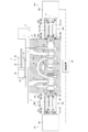
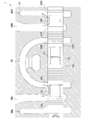
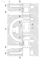
- FIG. 2 is a cross-sectional view showing a state in which the first spool is moved to a first supply position and the second spool is moved to a second discharge position in the flow control valve of FIG. 1.
- FIG. 2 is a cross-sectional view showing a state in which the first spool is moved to a first discharge position and the second spool is moved to a second supply position in the flow control valve of FIG. 1.
- FIG. 2 is a cross-sectional view illustrating a state in which the first spool is independently moved in one axial direction in the flow control valve of FIG. 1.
- FIG. 2 is a cross-sectional view showing a state in which the first spool is moved independently in the other axial direction in the flow control valve of FIG. 1.
- FIG. 2 is a cross-sectional view showing a state in which the second spool is pushed and moved by the first spool in the flow control valve of FIG. 1.
- a flow control valve device 1 according to an embodiment of the present invention will be described with reference to the drawings.
- the concept of the direction used in the following description is used for convenience in description, and does not limit the direction of the configuration of the invention in that direction.
- the flow control valve device 1 described below is only one embodiment of the present invention. Therefore, the present invention is not limited to the embodiments, and additions, deletions, and changes can be made without departing from the spirit of the invention.
- An industrial machine for example, a hydraulic excavator, includes a plurality of hydraulic cylinders 2 as shown in FIG. 1, and by moving hydraulic oil to and from the hydraulic cylinders 2, components such as booms, arms, and buckets are moved. It has become.
- the hydraulic cylinder 2 is a double-acting hydraulic cylinder, for example, and has a head side oil chamber 2a and a rod side oil chamber 2b.
- hydraulic oil can be supplied to and discharged from the oil chambers 2a and 2b by the head side port 2d and the rod side port 2e, and the rod 2c moves forward and backward to move the constituent members by supplying and discharging. It has become.
- the hydraulic cylinder 2 configured in this manner is connected to a hydraulic pump 3 and a tank 4 via a flow rate control valve device 1.
- the flow control valve device 1 supplies hydraulic oil from the hydraulic pump 3 to the hydraulic cylinder 2 and controls the supplied flow rate. Further, the flow control valve device 1 discharges hydraulic oil from the hydraulic cylinder 2 to the tank 4 and controls the flow rate to be discharged. Thus, meter-in control and meter-out control are performed on the hydraulic cylinder 2 by the flow control valve device 1. Below, the structure of the flow control valve apparatus 1 is demonstrated.
- the flow control valve device 1 includes a block 11, two spools 12L and 12R, two actuators 14L and 14R, and two urging mechanisms 16L and 16R.
- the block 11 which is an example of a housing is a valve block, for example, and has at least one spool hole 21 formed therein.
- the spool hole 21 extends along a predetermined axis L1.
- the block 11 includes two tank ports 22L and 22R, two supply / discharge ports 24L and 24R, and two pump ports 26L and 26R. These six ports 22L to 26R are spools.
- the hole 21 is opened.
- the two tank ports 22L and 22R are arranged apart from each other in the axial direction in the block 11, and the two supply / discharge ports 24L and 24R are arranged between them.
- the pump ports 26L, 26R are disposed between the two supply / discharge ports 24L, 24R, and are both connected to the hydraulic pump 3 via the pump passage 28.
- the first supply / discharge port 24L which is the supply / discharge port 24L on one side in the axial direction, is connected to the head side port 2d of the hydraulic cylinder 2 via the first oil passage 29L, and the supply / discharge on the other side in the axial direction.
- the second supply / discharge port 24R which is the port 24R, is connected to the rod side port 2e of the hydraulic cylinder 2 via the second oil passage 29R. Further, the two tank ports 22L and 22R are connected to the tank 4 via the tank passages 30L and 30R. These six ports 22L to 26R are arranged at intervals in the axial direction. Two spools 12L and 12R are inserted into one spool hole 21 to switch the connection state of the six ports 22L to 26R arranged in this way.
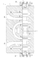
- the first spool 12L is formed in a substantially cylindrical shape as shown in FIG. 2, and is inserted into the spool hole 21 so as to be capable of reciprocating in the axial direction.
- the first spool 12L is arranged on one side in the axial direction of the spool hole 21, and the connection state of the three ports 22L, 24L, 26L arranged on the one side in the axial direction is changed by changing the position thereof. It has become. More specifically, in the first spool 12L, a round 13L is formed in the intermediate portion over the entire circumference in the circumferential direction, and the connection state can be changed by changing the position of the round 13L.
- the round 13L is connected only to the first supply / discharge port 24L in a state where the first spool 12L is located at the first neutral position, and the remaining two ports 22L and 26L are connected by the outer peripheral surface of the first spool 12L. It is blocked. As a result, the three ports 22L, 24L, and 26L are blocked.
- the opening degree between the first tank port 22L and the first supply / discharge port 24L can be adjusted by moving the first spool 12L.
- the first spool 12L is moved to the other side in the axial direction and positioned at the first supply position, the other axial side of the round 13L opens to the first pump port 26L, and the first pump port 26L and the first supply / discharge The port 24L is connected via the round 13L.
- the opening degree between the first pump port 26L and the first supply / discharge port 24L can be adjusted by moving the first spool 12L.
- the second spool 12R is also configured in the same manner as the first spool 12L, is formed in a substantially cylindrical shape, and is inserted into the spool hole 21 so as to be capable of reciprocating in the axial direction.
- the second spool 12R is disposed on the other side in the axial direction of the spool hole 21, and the connection state of the three ports 22R, 24R, and 26R disposed on the other side in the axial direction is changed by changing the position thereof. It is like that. More specifically, in the second spool 12R, a round 13R is formed at the intermediate portion over the entire circumference. The connection state can be changed by changing the position of the round 13R.
- the round 13R is connected only to the second supply / discharge port 24R with the second spool 12R positioned at the second neutral position, and the remaining two ports 22R and 26R are blocked by the outer peripheral surface of the second spool 12R. It is. As a result, the three ports 22R, 24R, and 26R are blocked.
- the second spool 12R when the second spool 12R is moved to the other side in the axial direction to be positioned at the second discharge position, the other side in the axial direction of the round 13R opens to the second tank port 22R, and the second tank port 22R and the second supply / discharge The port 24R is connected via the round 13R. Further, the opening degree between the second tank port 22R and the second supply / discharge port 24R can be adjusted by moving the second spool 12R.
- the second spool 12R when the second spool 12R is moved to one side in the axial direction and positioned at the second supply position, one side in the axial direction of the round 13R opens to the second pump port 26R, and the second pump port 26R and the second supply / discharge The port 24R is connected via the round 13R. Further, the opening between the second pump port 26R and the second supply / discharge port 24R can be adjusted by moving the second spool 12R.
- the two spools 12L and 12R configured as described above are arranged so that the tip portions are abutted and close to each other in the axial direction.
- the two spools 12L and 12R are disposed between the tip portions.
- the gaps X are arranged close to each other so as to leave a gap.
- the clearance X is set to about 10% with respect to the maximum stroke length of each of the two spools 12L and 12R. Note that the gap X between the two spools 12L and 12R is not limited to the above value.
- the clearance X is, for example, 2 in consideration of the ratio of the minimum stroke length necessary for each spool to move from the neutral position to the supply position and the discharge position (about 2% in this embodiment) with respect to the maximum stroke length. It is preferably set within a range of 5% to 40% with respect to the maximum stroke length of each of the two spools 12L, 12R. Note that the term “proximity” does not necessarily include a case where the two spools 12L and 12R are in contact with each other. As shown in FIG. 1, the first and second actuators 14L and 14R are respectively provided at the base end portions of the two spools 12L and 12R arranged close to each other as described above.
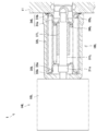
- the first and second actuators 14L and 14R also shown in FIG. 3 are, for example, direct acting electric actuators, and are constituted by servo motors and ball screws (both not shown) accommodated in the casings 15L and 15R.
- the direct acting electric actuator has, for example, a ball screw formed by screwing a slider (nut) (both not shown) to a screw shaft, and the slider is reciprocated in the axial direction by rotating the screw shaft by a servo motor. It comes to exercise.
- the slider having such a function is fixed to the driving bodies 31L and 31R provided in the first and second actuators 14L and 14R, respectively.
- Each of the driving bodies 31L and 31R is formed in a substantially cylindrical shape, and a slider is fixed to one end portion in the axial direction (not shown). Further, the other end portion in the axial direction of the first driving body 31L is fixed to the end portion on one side in the axial direction of the first spool 12L, and when a current is passed through the first actuator 14L to rotate the servo motor, The first spool 12L can be moved in one axial direction and the other in the axial direction by a driving force corresponding to the current. On the other hand, the other end portion in the axial direction of the second drive body 31R is fixed to the other end portion in the axial direction of the second spool 12R.
- the second spool 12R When a current is passed through the second actuator 14R to rotate the servo motor, The second spool 12R can be moved in one axial direction and the other in the axial direction by a driving force corresponding to the current. Thus, the first and second spools 12L and 12R can be moved independently of each other by using the first and second actuators 14L and 14R.
- the first and second actuators 14L and 14R configured as described above are both mounted with the driving bodies 31L and 31R fixed to the base ends of the spools 12L and 12R.
- the second actuator 14 ⁇ / b> R is disposed so as to project to the other side in the axial direction of the block 11.
- Each of the first and second drive bodies 31R and 31R protrudes from the casings 15L and 15R of the first and second actuators 14L and 14R, respectively. Thereby, there is a space between the casings 15L and 15R and the block 11, and biasing mechanisms 16L and 16R are provided between the casings 15L and 15R and the block 11, respectively.
- the first urging mechanism 16L includes a casing member 32L, two spring receiving members 33L and 34L, coil springs 35L and 36L, and a stopper member 37L.
- the casing member 32L is a bottomed cylindrical member having a substantially U-shaped cross section cut along a virtual plane including the axis thereof, and covers the first driving body 31L through the casing member 32L.
- the casing member 32L is attached to the side surface on one side in the axial direction of the block 11 with its open end sealed, and the casing 15L of the first actuator 14L is fixed to the bottom.
- two spring receiving members 33L and 34L, coil springs 35L and 36L, and a stopper member 37L are accommodated.
- the two spring receiving members 33L and 34L have main body portions 33a and 34a and flanges 33b and 34b, respectively.
- the main body portions 33a and 34a are formed in a bottomed cylindrical shape having a substantially U-shaped section cut along a virtual plane including the axis thereof, and the flanges 33b and 34b are outer peripheral surfaces of the open ends of the main body portions 33a and 34a. Are formed so as to project outward in the radial direction over the entire circumference in the circumferential direction.
- the first spring receiving member 33L which is one of the spring receiving members 33L, is disposed on one side in the axial direction in the casing member 32L, and the flange 33b is disposed in a state where the first spool 12L is positioned at the first neutral position. It is made to contact
- the first driver 31L is formed with an enlarged diameter portion 31a, and the enlarged diameter portion 31a is disposed in the first spring receiving member 33L and is in contact with the inner end face of the first spring receiving member 33L. .
- a second spring receiving member 34L is disposed in the casing member 32L so as to face the first spring receiving member 33L.
- the second spring receiving member 34L which is the other spring receiving member 34L, is disposed on the other side in the axial direction in the casing member 32L, and the flange 34b is moved in a state where the first spool 12L is located at the first neutral position.
- the block 11 is in contact with a side surface on one side in the axial direction. Further, the end of one axial direction of the first spool 12L protrudes from the spool hole 21 of the block 11, and the protruding portion is fitted to the second spring receiving member 34L.
- the second spring receiving member 34L moves to the one side in the axial direction in accordance with the movement of the first spool 12L that moves together with the first driving body 31L. It has become.
- the second spring receiving member 34L arranged in this manner is arranged opposite to the first spring receiving member 33L and spaced from each other. Between these two spring bearing members 33L and 34L, two coil springs 35L and 36L are interposed in order to press them against the bottom and side surfaces, respectively.
- the two coil springs 35L and 36L are so-called compression coil springs, and the first coil spring 35L, which is one coil spring 35L, is armored at one end side in the axial direction on the main body portion 33a of the first spring receiving member 33L, and the axial direction The other end side is covered with the main body 34a of the second spring receiving member 34L. Further, each end portion of the first coil spring 35L is in contact with the flanges 33b, 34b of the first and second spring receiving members 33L, 34L. A second coil spring 36L is disposed inside the first coil spring 35L.
- the second coil spring 36L is externally mounted on the first driving body 31L, and its one axial end is in contact with the bottom of the main body 33a of the first spring receiving member 33L, and the other axial end is the second spring receiver.
- the member 34L is in contact with the bottom of the main body 34a.
- a stopper member 37L is disposed inside the second coil spring 36L.
- the stopper member 37L is formed in a substantially cylindrical shape and is externally mounted on the first drive body 31L.
- the stopper member 37L is fixed to the bottom of the main body 34a of the second spring receiving member 34L.
- the stopper member 37L is interposed between the two spring bearing members 33L and 34L as described above. That is, the stopper member 37L is configured such that when the two spring bearing members 33L and 34L are relatively displaced so as to approach each other, when the relative displacement amount reaches a predetermined amount, the stopper member 37L hits the first spring receiving member and does not further displace.
- the relative displacement amount is restricted to a predetermined amount or less. This restricts the first spool 12L from moving in the axial direction to one side and the other by a predetermined amount or more.
- the two coil springs 35L and 36L resist the driving force of the first actuator 14L. And generate an urging force.
- the two coil springs 35L and 36L generate an urging force corresponding to the amount of compression, that is, the position of the first spool 12L.
- the first spool 12L moves to a position where the driving force of the first actuator 14L and the biasing force of the two coil springs 35L, 36L are balanced, and the position according to the current flowing through the first actuator 14L. Can be moved to.
- the first biasing mechanism 16L can move the first spool 12L to an arbitrary position in cooperation with the first actuator 14L.
- the second spool 12R is provided with a second urging mechanism 16R in order to move the second spool 12R to an arbitrary position.
- the second urging mechanism 16R has the same configuration as the first urging mechanism 16L. Therefore, regarding the configuration of the second urging mechanism 16R, regarding the same configuration as the first urging mechanism 16L, the reference numeral “L” is substituted for “R”, and the configuration of the first urging mechanism 16L is related. The detailed description is omitted with reference to the description. That is, the second urging mechanism 16R includes a casing member 32R, two spring receiving members 33R and 34R, coil springs 35R and 36R, and a stopper member 37R.
- the second urging mechanism 16R is attached to the side surface on the other side in the axial direction of the block 11 in a state where the second driving body 31R is passed through the casing member 32R and the opening end of the casing member 32R is sealed. . Further, in the second urging mechanism 16R, the casing 15R of the second actuator 14R is fixed to the bottom of the casing member 32R.
- the second urging mechanism 16R configured as described above, when the second spool 12R is pushed and pulled in the axial direction by the second actuator 14R, the two coil springs 35R and 36R resist the driving force of the second actuator 14R. And generate an urging force.
- the two coil springs 35R and 36R generate an urging force corresponding to the amount of compression, that is, the position of the second spool 12R.
- the second spool 12R moves to a position where the driving force of the second actuator 14R and the urging force of the two coil springs 35R, 36R are balanced, and the position corresponding to the current flowing through the second actuator 14R. Can be moved to.
- the second urging mechanism 16R can move the second spool 12R to an arbitrary position in cooperation with the second actuator 14R.
- the two actuators 14L and 14R are connected to the control device 40, and the operations of the two actuators 14L and 14R are controlled by the control device 40 (FIG. 1). reference). More specifically, the control device 40 causes the two actuators 14L and 14R to pass a current corresponding to an operation (for example, an operation direction and an operation amount) of an operation tool (not shown) such as an operation lever, and the flow control valve device. Control the movement of 1.
- the control device 40 is configured by a so-called computer.
- the control device 40 includes a CPU (Central Processing Unit), a ROM (Read Only Memory), a RAM (Random Access Memory), an I / F (Interface), an I / O (Input / output Port), and the like. (Neither shown).
- the ROM stores programs executed by the CPU, various fixed data, and the like. Programs executed by the CPU are stored in various storage media such as a flexible disk, a CD-ROM, and a memory card, and are installed in the ROM from these storage media.
- the RAM temporarily stores data necessary for program execution.
- the I / F performs data transmission / reception with an external device (for example, an input device or storage device not shown). I / O inputs / outputs detection signals of various sensors.
- the control device 40 is configured to perform processing for realizing each function by cooperation of software such as a program stored in the ROM and hardware such as a CPU. Below, operation
- the first driver 31L moves to the other side in the axial direction.
- the first spool 12L located at the first neutral position moves to the other side in the axial direction as shown in FIG. 4, and eventually the first spool 12L is located at the first supply position.
- the other axial side of the round 13L opens to the first pump port 26L, and the first pump port 26L and the first supply / discharge port 24L are connected via the round 13L.
- the first tank port 22L is not connected to any of the ports 24L and 26L and is blocked.
- the first drive body 31L moves the first spool 12L to the other side in the axial direction
- the first spring receiving member 33L is pushed to the other side in the axial direction, and the two coil springs 35L, It is energized from 36L. Therefore, the first spool 12L eventually reaches a position where the driving force of the first actuator 14L and the urging force of the two coil springs 35L, 36L are balanced, and stops at that position.
- the opening degree between the first pump port 26L and the first supply / discharge port 24L is set to the opening degree corresponding to the current flowing through the first actuator 14L (that is, the opening degree corresponding to the operation amount of the operating tool). Adjusted.
- the second driver 31R moves to the other side in the axial direction.
- the second spool 12R that has been located at the second neutral position moves to the other side in the axial direction, and eventually the second spool 12R is located at the second discharge position.
- the other axial side of the round 13R opens to the second tank port 22R, and the second tank port 22R and the second supply / discharge port 24R are connected via the round 13R.
- the second pump port 26R is not connected to any of the ports 22R and 24R and is blocked.
- the second driving body 31R moves the second spool 12R to the other side in the axial direction
- the second driving body 31R pulls the second spring receiving member 34R to the other side in the axial direction via the second spool 12R, and the compression is accordingly performed.
- the biasing force is received from the two coil springs 35R and 36R. Therefore, the second spool 12R eventually reaches a position where the driving force of the second actuator 14R and the urging force of the two coil springs 35R, 36R are balanced, and stops at that position.
- the opening between the second tank port 22R and the second supply / discharge port 24R is set to the opening corresponding to the current flowing through the second actuator 14R (that is, the opening corresponding to the operation amount of the operating tool). Adjusted.
- the first spool 12L moves to the first supply position
- the second spool 12R moves to the second discharge position.
- the head side port 2 d of the hydraulic cylinder 2 is connected to the pump 3
- the rod side port 2 e is connected to the tank 4.
- hydraulic oil is supplied from the pump 3 to the head side oil chamber 2a, and the hydraulic oil in the rod side oil chamber 2b is discharged to the tank 4 so that the hydraulic cylinder 2 can be extended.
- Each of the opening between the first pump port 26L and the first supply / discharge port 24L and the opening between the second tank port 22R and the second supply / discharge port 24R depends on the operation amount of the operating tool.
- the meter-in control and the meter-out control are executed with respect to the flow rate of the hydraulic oil supplied to and discharged from the hydraulic cylinder 2.
- the speed at which the hydraulic cylinder 2 is extended that is, the operation speed can be set to a speed corresponding to the operation amount of the operation tool.
- the control device 40 stops the current flowing through each of the two actuators 14L and 14R. Then, the first spring receiving member 33L is pushed back by the two coil springs 35L and 36L to a position where the first spring receiving member 33L contacts the bottom of the casing member 32L, and accordingly, the first driving body 31L is returned to the one side in the axial direction. As a result, the first spool 12L returns to the first neutral position (see FIG. 1).
- the second spring receiving member 34R is pushed back to a position where it abuts against the side surface of the block 11, and accordingly, the second spool 12R is pushed to one side in the axial direction and the second driving body. 31R is returned. As a result, the second spool 12R returns to the second neutral position (see FIG. 1).
- the control device 40 detects the operated direction and the operation amount, which is opposite to the case where the operation is performed in one operation direction. Is supplied to the two actuators 14L and 14R. Thereby, the flow control valve apparatus 1 moves as follows.
- the first driver 31L moves to one side in the axial direction.
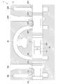
- the first spool 12L located at the first neutral position moves to one side in the axial direction as shown in FIG. 5, and eventually the first spool 12L is located at the first discharge position.
- the axial direction one side of the round 13L opens to the first tank port 22L, and the first tank port 22L and the first supply / discharge port 24L are connected via the round 13L.
- the first pump port 26L is blocked without being connected to any of the ports 22L and 24L.
- the first drive body 31L moves the first spool 12L to the one side in the axial direction
- the first drive body 31L pulls the second spring receiving member 34L to the one side in the axial direction via the first spool 12L, and compresses accordingly.
- the two coil springs 35L and 36L are biased. Therefore, the first spool 12L eventually reaches a position where the driving force of the first actuator 14L and the urging force of the two coil springs 35L, 36L are balanced, and stops at that position.
- the opening degree between the first pump port 26L and the first supply / discharge port 24L is set to the opening degree corresponding to the current flowing through the first actuator 14L (that is, the opening degree corresponding to the operation amount of the operating tool). Adjusted.
- the second driver 31R moves to one side in the axial direction.
- the second spool 12R located at the second neutral position moves to one side in the axial direction, and eventually the second spool 12R is located at the second supply position.
- the axial direction one side of round 13R opens to the 2nd pump port 26R, and the 2nd pump port 26R and the 2nd supply / discharge port 24R are connected via round 13R.
- the second tank port 22R is not connected to any of the ports 24R and 26R and is blocked.
- the second drive body 31R moves the second spool 12R to the one side in the axial direction
- the first spring receiving member 33R is pushed to the one side in the axial direction, and the two coil springs 35R, It is energized by 36R. Therefore, the second spool 12R eventually reaches a position where the driving force of the second actuator 14R and the urging force of the two coil springs 35R, 36R are balanced, and stops at that position.
- the opening degree between the second pump port 26R and the second supply / discharge port 24R is set to the opening degree corresponding to the opening degree corresponding to the current flowing through the second actuator 14R (that is, the operation amount of the operating tool). Adjusted.
- the first spool 12L moves to the first discharge position
- the second spool 12R moves to the second supply position.
- the head side port 2 d of the hydraulic cylinder 2 is connected to the tank 4, and the rod side port 2 e is connected to the pump 3.
- the hydraulic oil is supplied from the pump 3 to the rod side oil chamber 2b, and the hydraulic oil in the head side oil chamber 2a is discharged to the tank 4 so that the hydraulic cylinder 2 can be contracted.
- Each of the opening between the first tank port 22L and the first supply / discharge port 24L and the opening between the second pump port 26R and the second supply / discharge port 24R depends on the operation amount of the operating tool.
- the meter-in control and the meter-out control are executed with respect to the flow rate of the hydraulic oil supplied to and discharged from the hydraulic cylinder 2.
- the speed at which the hydraulic cylinder 2 contracts that is, the operation speed can be set to a speed according to the operation amount of the operation tool.
- the control device 40 stops the current flowing through each of the two actuators 14L and 14R as in the case described above. Then, the second spring receiving member 34L is pushed back to the position where it abuts against the side surface of the block 11 by the two coil springs 35L, 36L, and accordingly, the first spool 12L is pushed back and the first driver 31L is returned. As a result, the first spool 12L returns to the first neutral position (see FIG. 1).
- the first spring receiving member 33R is pushed back to the position where it abuts against the bottom of the casing member 32R by the two coil springs 35R, 36R, and accordingly, the second drive body 31R is returned to the other side in the axial direction.
- the second spool 12R returns to the second neutral position (see FIG. 1).
- all of the six ports 22L to 26R are blocked, the contraction of the hydraulic cylinder 2 is stopped, and the state is maintained.
- the flow control valve device 1 configured as described above further has the following functions.
- the direction and size of its own weight acting on a component member differs depending on the posture of the component member such as a boom, and the operation speed of the component member changes depending on the direction and size. It is preferable that the change in the operation speed of the hydraulic cylinder 2 with respect to the operation amount of the operation tool can be suppressed due to the influence of the direction and size of the own weight.
- two spools 12L and 12R formed separately in the spool hole 21 are inserted, and separate actuators 14L and 14R are provided for the two spools 12L and 12R to move independently of each other. It can be done. Therefore, the two spools 12L and 12R moved together to expand and contract the hydraulic cylinder 2 are individually moved from that position, and the flow rate of hydraulic oil supplied to and discharged from the hydraulic cylinder 2 is independently controlled. Can do.
- the gap X is formed between the two spools 12L and 12R, and the two spools 12L and 12R are close to each other as long as the movement amount is less than the gap X. Even if it moves in the direction, it can be moved independently without hitting each other. Therefore, as shown in FIG. 7, without moving the second spool 12R, the first spool 12L in the first supply position can be moved closer to the second spool 12R (that is, to the other side in the axial direction). it can.
- the first spool 12L is moved to the other side in the axial direction, and the second spool 12R is also moved to the other side in the axial direction to increase the opening between the second tank port 22R and the second supply / discharge port 24R. May be. Thereby, the resistance at the time of discharging hydraulic oil can be suppressed.
- the hydraulic cylinder 2 is supplied and discharged in the same manner as when the meter-in flow control valve and the meter-out flow control valve are separately provided for the hydraulic cylinder 2.
- the flow rate of hydraulic oil can be controlled independently. Therefore, the control device 40 detects the direction and size of the weight of the component member in advance, controls the current flowing through the first actuator 14L, and restricts the amount by which the opening is reduced, thereby limiting the hydraulic pressure relative to the operation amount of the operation tool. The influence of the weight of the component member on the operating speed of the cylinder 2 can be suppressed.
- the flow control valve device 1 is different from the case where the meter-in flow control valve and the meter-out flow control valve are separately provided for the hydraulic cylinder 2 in the two spools 12L and 12R in one spool hole 21. It is configured by inserting. Therefore, in the flow control valve device 1, the number of spool holes 21 of the block 11 to be used can be minimized, and an increase in the size of the block 11 can be suppressed.
- the flow control valve device 1 since the two spools 12L and 12R are arranged close to each other in the flow control valve device 1, the flow control valve device 1 operates as follows. That is, it can be used even when one of the two actuators 14L, 14R cannot be driven due to disconnection or the like and cannot be driven. For example, when the connection between the second actuator 14R and the control device 40 is disconnected and the second actuator 14R malfunctions, the second spool 12R does not move from the second neutral position. On the other hand, when a current flows from the control device 40 to the first actuator 14L, the first spool 12L moves to the other side in the axial direction, approaches the second spool 12R, and eventually comes into contact (see FIG. 8).
- the first spool 12L pushes the second spool 12R to the other side in the axial direction, and the first and second spools 12L, 12R are Moves integrally in the other direction.
- the first spool 12L can be moved to the second offset position, and the second spool 12R that has stopped moving from the second neutral position can be moved toward the first offset position.
- the movement amount of the first spool 12L is regulated by the gap X. That is, the second spool 12R serves as a stopper.
- the gap X is defined in advance according to the relationship between the ports 22L to 26R and the rounds 13L and 13R (for example, the length and arrangement position) and the lengths of the spools 12L and 12R.
- An excessive opening between the port 26L and the first supply / discharge port 24L can be suppressed. Thereby, it can prevent that the oil_pressure
- the first actuator 14L eventually moves the first spool 12L toward the other side in the axial direction, that is, in the direction approaching the second spool 12R. 12L contacts the second spool 12R. Furthermore, by moving the first spool 12L to the other side in the axial direction, the second spool 12R can be forcibly pushed, and the fact that the second spool 12R is fixed can be eliminated. Similarly, when the first spool 12L is fixed, it can be solved that the first spool 12L is fixed.
- tank ports 22 ⁇ / b> L and 22 ⁇ / b> R are formed outside the block 11. Therefore, when the actuators 14L, 14R become inoperable or the spools 12L, 12R become inoperable, even if one of the spools 12L, 12R is moved away from the other, the supply / discharge port 24L, Since 24R is only connected to the tank ports 22L and 22R, fail-safe can be achieved.
- the flow control valve device 1 employs first and second actuators that can be pushed and pulled in order to move the spools 12L and 12R.
- the two spools 12L and 12R can be reciprocated in the axial direction only by arranging the actuators on one side in the axial direction of the spool 12L and on the other side in the axial direction of the spool 12R. Accordingly, the size of the flow control valve device 1 can be reduced as compared with the case where the drive units are provided on both axial sides of the two spools 12L and 12R.
- the flow control valve device 1 uses a direct-acting electric actuator constituted by a servo motor and a ball screw, the positions of the two spools 12L and 12R can be adjusted with high accuracy. Thereby, the flow volume according to an electric current can be supplied and discharged
- the flow control valve device 1 of the present embodiment has been described as applied to a hydraulic excavator, the applied industrial machine is not limited to a hydraulic excavator and may be an industrial machine including a hydraulic cylinder such as a wheel loader or a crane. Good.
- the device to which the flow control valve device 1 is applied is not limited to a hydraulic cylinder, and may be a hydraulic device such as a hydraulic motor.
- the ports formed in the block 11 are formed in the order of the tank ports 22L, 22R, the supply / discharge ports 24L, 24R, and the pump ports 26L, 26R from the outside to the inside.
- the arrangement position is not limited.
- the tank ports 22L and 22R, the supply / discharge ports 24L and 24R, and the pump ports 26L and 26R may be formed in this order from the inside toward the outside.
- two rounds are formed in each of the spools 12L and 12R, and each round is arranged to face each of the tank ports 22L and 22R and the pump ports 26L and 26R in the neutral position. Further, only the positions of the second tank port 22R and the second pump port 26R may be exchanged.
- linear motion electric actuators using ball screws are employed for the first and second actuators 14L, 14R, but such a configuration is not necessarily required.
- the two spools 12L and 12R can be moved linearly, they may be linearly moved using a linear motor, a voice coil motor, a cam mechanism, a rack and pinion mechanism, or the like.
- the two spools 12L and 12R are arranged close to each other, but they are not necessarily arranged close to each other and may be arranged apart from each other.
Landscapes
- Engineering & Computer Science (AREA)
- General Engineering & Computer Science (AREA)
- Mechanical Engineering (AREA)
- Physics & Mathematics (AREA)
- Electromagnetism (AREA)
- Fluid Mechanics (AREA)
- Multiple-Way Valves (AREA)
- Servomotors (AREA)
- Valve Housings (AREA)
- Operation Control Of Excavators (AREA)
Abstract
Description
本発明の上記目的、他の目的、特徴、及び利点は、添付図面参照の下、以下の好適な実施態様の詳細な説明から明らかにされる。
流量制御弁装置1は、ブロック11と、2つのスプール12L,12Rと、2つのアクチュエータ14L,14Rと、2つの付勢機構16L,16Rとを有している。ハウジングの一例であるブロック11は、例えばバルブブロックであり、少なくとも1つのスプール孔21が形成されている。スプール孔21は、予め定められた軸線L1に沿って延在している。また、ブロック11は、2つのタンクポート22L,22Rと、2つの給排ポート24L,24Rと、2つのポンプポート26L,26Rとが形成されており、これらの6つのポート22L~26Rは、スプール孔21に開口している。
油圧シリンダー2を伸長させるべく、操作者が操作具を操作方向一方に操作すると、制御装置40は、操作された方向及び操作量(例えば、油圧又はセンサ値)を検出し、それらの応じた別々の電流を2つのアクチュエータ14L,14Rに流す。これにより、流量制御弁装置1が以下のように動く。
また、例えば、第2スプール12Rが第2中立位置で動かなくなった場合、第1アクチュエータ14Lが第1スプール12Lを軸線方向他方側、即ち第2スプール12Rに近づく方向に動かすと、やがて第1スプール12Lが第2スプール12Rに当接する。更に、第1スプール12Lを軸線方向他方側に動かすことによって、第2スプール12Rを強制的に押し、第2スプール12Rが固着していることを解消することができる。第1スプール12Lが固着した場合も同様にして、第1スプール12Lが固着していることを解消することができる。
本実施形態の流量制御弁装置1は、油圧ショベルに適用した場合について説明したが、適用される産業機械は、油圧ショベルに限定されず、ホイルローダやクレーン等の油圧シリンダーを備える産業機械であればよい。また、流量制御弁装置1が適用される機器もまた、油圧シリンダーに限定されず、油圧モータ等の液圧機器であればよい。
11 ブロック
12L スプール
12R スプール
14L 第1アクチュエータ
14R 第2アクチュエータ
16L 第1付勢機構
16R 第2付勢機構
21 スプール孔
22L 第1タンクポート
22R 第2タンクポート
24L 第1給排ポート
24R 第2給排ポート
26L 第1ポンプポート
26R 第2ポンプポート
Claims (6)
- 第1ポンプポートと、第2ポンプポートと、第1タンクポートと、第2タンクポートと、第1給排ポートと、第2給排ポートを有すると共に、これらのポート全てが開口するスプール孔と、ハウジングと、
位置に応じて前記第1ポンプポート、前記第1タンクポート、及び前記第1給排ポートの接続状態を切換える第1スプールと、
前記第1ポンプポートと前記第1給排ポートとが接続される第1供給位置、及び前記第1タンクポートと前記第1給排ポートとが接続される第1排出位置の各々に前記第1スプールを移動させる第1アクチュエータと、
位置に応じて前記第2ポンプポート、前記第2タンクポート、及び前記第2給排ポートの接続状態を切換える第2スプールと、
前記第2ポンプポートと前記第2給排ポートとが接続される第2供給位置、及び前記第2タンクポートと前記第2給排ポートとが接続される第2排出位置の各々に前記第2スプールを移動させる第2アクチュエータとを備え、
前記第1スプール及び前記第2スプールは、1つの前記スプール孔に往復運動可能に挿入されている、流量制御弁装置。 - 2つの前記ポンプポート、2つの前記タンクポート、前記第1給排ポート、及び前記第2給排ポートは、前記第1スプール及び前記第2スプールが所定方向一方に移動すると前記第1スプールが第1供給位置に位置し且つ前記第2スプールが第2排出位置に位置し、前記第1スプール及び前記第2スプールが所定方向他方に移動すると前記第1スプールが第1排出位置に位置し且つ前記第2スプールが第2供給位置に位置するように配置されている、請求項1に記載の流量制御弁装置。
- 前記第1及び第2スプールは、互いに近接させて前記スプール孔に配置されている、請求項2に記載の流量制御弁装置。
- 前記第1アクチュエータは、前記第1スプールを押し引きして前記第1スプールを往復運動させ、
前記第2アクチュエータは、前記第2スプールを押し引きして前記第2スプールを往復運動させ、
前記第1アクチュエータは、前記ハウジングの所定方向一方側に配置され、
前記第2アクチュエータは、前記ハウジングの所定方向他方側に配置されている、請求項2又は3に記載の流量制御弁装置。 - 前記第1アクチュエータの押し引きに抗して前記第1スプールを付勢する第1付勢機構と、
前記第2アクチュエータの押し引きに抗して前記第2スプールを付勢する第2付勢機構と、を備え、
前記第1スプールは、第1中立位置で、前記第1ポンプポート、前記第1タンクポート、及び前記第1給排ポートの各々を遮断し、
前記第2スプールは、第2中立位置で、前記第2ポンプポート、前記第2タンクポート、及び前記第2給排ポートの各々を遮断し、
前記第1付勢機構は、前記第1スプールを第1中立位置に付勢し、
前記第2付勢機構は、前記第2スプールを第2中立位置に付勢する、請求項4に記載の流量制御弁装置。 - 前記第1アクチュエータ及び前記第2アクチュエータは、直動電動アクチュエータである、請求項1乃至5の何れか1つに記載の流量制御弁装置。
Priority Applications (4)
| Application Number | Priority Date | Filing Date | Title |
|---|---|---|---|
| US16/308,515 US10859175B2 (en) | 2016-06-10 | 2017-05-18 | Flow control valve apparatus |
| GB1900254.2A GB2565988B (en) | 2016-06-10 | 2017-05-18 | Flow control valve apparatus |
| KR1020197000019A KR102207185B1 (ko) | 2016-06-10 | 2017-05-18 | 유량 제어 밸브 장치 |
| CN201780034000.5A CN109154397B (zh) | 2016-06-10 | 2017-05-18 | 流量控制阀装置 |
Applications Claiming Priority (2)
| Application Number | Priority Date | Filing Date | Title |
|---|---|---|---|
| JP2016116296A JP6815103B2 (ja) | 2016-06-10 | 2016-06-10 | 流量制御弁装置 |
| JP2016-116296 | 2016-06-10 |
Publications (1)
| Publication Number | Publication Date |
|---|---|
| WO2017212892A1 true WO2017212892A1 (ja) | 2017-12-14 |
Family
ID=60577714
Family Applications (1)
| Application Number | Title | Priority Date | Filing Date |
|---|---|---|---|
| PCT/JP2017/018704 Ceased WO2017212892A1 (ja) | 2016-06-10 | 2017-05-18 | 流量制御弁装置 |
Country Status (6)
| Country | Link |
|---|---|
| US (1) | US10859175B2 (ja) |
| JP (1) | JP6815103B2 (ja) |
| KR (1) | KR102207185B1 (ja) |
| CN (1) | CN109154397B (ja) |
| GB (1) | GB2565988B (ja) |
| WO (1) | WO2017212892A1 (ja) |
Cited By (1)
| Publication number | Priority date | Publication date | Assignee | Title |
|---|---|---|---|---|
| CN110778761A (zh) * | 2019-11-28 | 2020-02-11 | 宇通物联网技术(深圳)有限公司 | 一种流量压控阀 |
Families Citing this family (6)
| Publication number | Priority date | Publication date | Assignee | Title |
|---|---|---|---|---|
| WO2018097963A1 (en) * | 2016-11-22 | 2018-05-31 | Parker-Hannifin Corporation | Ultra-low carryover solenoid valve |
| WO2021093405A1 (zh) * | 2019-11-13 | 2021-05-20 | 廊坊市金色时光科技发展有限公司 | 一种泵阀模组及其操作方法、用于汽车座椅的按摩电磁阀泵阀模组及汽车座椅 |
| EP3845767B1 (en) * | 2019-12-30 | 2024-07-24 | Danfoss Power Solutions Aps | Valve group |
| JP7468220B2 (ja) * | 2020-07-23 | 2024-04-16 | 株式会社デンソー | 流路切替装置 |
| JP7474346B2 (ja) * | 2020-10-13 | 2024-04-24 | 川崎重工業株式会社 | 方向・流量制御弁および液圧システム |
| JP7561010B2 (ja) * | 2020-11-17 | 2024-10-03 | 川崎重工業株式会社 | マルチ制御弁 |
Citations (2)
| Publication number | Priority date | Publication date | Assignee | Title |
|---|---|---|---|---|
| JPH06129567A (ja) * | 1992-06-05 | 1994-05-10 | Trinova Ltd | 2段流体スプール弁 |
| JP2016053410A (ja) * | 2014-09-04 | 2016-04-14 | Smc株式会社 | デュアル4ポート電磁弁 |
Family Cites Families (15)
| Publication number | Priority date | Publication date | Assignee | Title |
|---|---|---|---|---|
| US3060969A (en) * | 1960-02-24 | 1962-10-30 | Alkon Products Corp | Hydraulic valve |
| US4565219A (en) * | 1982-09-13 | 1986-01-21 | The Oilgear Japan Company | Multiple-position solenoid-operated control valve |
| US4763691A (en) * | 1985-09-03 | 1988-08-16 | Barmag Barmer Maschinenfabrik Aktiengesellschaft | Hydraulic control valve |
| JPS6469878A (en) * | 1987-09-10 | 1989-03-15 | Diesel Kiki Co | Solenoid proportional pressure control valve |
| DE3817120A1 (de) * | 1988-05-19 | 1989-11-30 | Herion Werke Kg | Sicherheitsventil |
| JP3289852B2 (ja) | 1993-08-12 | 2002-06-10 | 株式会社小松製作所 | 流量応援用方向制御弁 |
| DE4496042T1 (de) | 1993-08-12 | 1996-06-27 | Komatsu Mfg Co Ltd | Durchflussverstärkendes Wegeventil für eine hydraulische Schaltung |
| KR0141305B1 (ko) | 1994-09-30 | 1998-06-15 | 배순훈 | 대역 분할 영상 부호화 방법 |
| JPH10141305A (ja) | 1996-11-15 | 1998-05-26 | Kenji Masuda | 油圧制御装置 |
| AT3017U3 (de) * | 1999-03-18 | 2000-03-27 | Hoerbiger Hydraulik | Steueranordnung für einen arbeitszylinder |
| JP2013249900A (ja) | 2012-05-31 | 2013-12-12 | Hitachi Constr Mach Co Ltd | 油圧駆動回路 |
| CN202833386U (zh) * | 2012-09-20 | 2013-03-27 | 三一重工股份有限公司 | 一种滑阀式液压阀及工程机械 |
| CN102865264B (zh) * | 2012-10-22 | 2015-09-16 | 三一重机有限公司 | 一种液压阀及液压阀组 |
| CN103912532B (zh) * | 2014-03-18 | 2016-01-13 | 浙江大学 | 一种双阀芯可编程控制液压阀 |
| US9903396B2 (en) * | 2016-03-08 | 2018-02-27 | Caterpillar Inc. | Valve assembly |
-
2016
- 2016-06-10 JP JP2016116296A patent/JP6815103B2/ja active Active
-
2017
- 2017-05-18 US US16/308,515 patent/US10859175B2/en active Active
- 2017-05-18 CN CN201780034000.5A patent/CN109154397B/zh active Active
- 2017-05-18 WO PCT/JP2017/018704 patent/WO2017212892A1/ja not_active Ceased
- 2017-05-18 KR KR1020197000019A patent/KR102207185B1/ko active Active
- 2017-05-18 GB GB1900254.2A patent/GB2565988B/en active Active
Patent Citations (2)
| Publication number | Priority date | Publication date | Assignee | Title |
|---|---|---|---|---|
| JPH06129567A (ja) * | 1992-06-05 | 1994-05-10 | Trinova Ltd | 2段流体スプール弁 |
| JP2016053410A (ja) * | 2014-09-04 | 2016-04-14 | Smc株式会社 | デュアル4ポート電磁弁 |
Cited By (1)
| Publication number | Priority date | Publication date | Assignee | Title |
|---|---|---|---|---|
| CN110778761A (zh) * | 2019-11-28 | 2020-02-11 | 宇通物联网技术(深圳)有限公司 | 一种流量压控阀 |
Also Published As
| Publication number | Publication date |
|---|---|
| JP6815103B2 (ja) | 2021-01-20 |
| KR20190014062A (ko) | 2019-02-11 |
| US10859175B2 (en) | 2020-12-08 |
| CN109154397A (zh) | 2019-01-04 |
| GB2565988B (en) | 2021-09-22 |
| JP2017219178A (ja) | 2017-12-14 |
| GB201900254D0 (en) | 2019-02-27 |
| GB2565988A (en) | 2019-02-27 |
| US20190162324A1 (en) | 2019-05-30 |
| CN109154397B (zh) | 2020-08-11 |
| KR102207185B1 (ko) | 2021-01-25 |
Similar Documents
| Publication | Publication Date | Title |
|---|---|---|
| WO2017212892A1 (ja) | 流量制御弁装置 | |
| JP5666174B2 (ja) | 多連方向切換弁 | |
| US10443746B2 (en) | Pressure reducing valve unit | |
| US9435446B1 (en) | Rotary valve with brake mode | |
| JP4997163B2 (ja) | サーボレギュレータ | |
| US11592000B2 (en) | Servoless motor | |
| EP2479439B1 (en) | Aircraft actuator | |
| JP2013113393A (ja) | 回転式液圧弁 | |
| US20150013804A1 (en) | Flow responsive latch for holding a spool valve in an open position | |
| EP2878816B1 (en) | Pump control device | |
| JP2013204558A (ja) | サーボレギュレータ | |
| US9915355B2 (en) | Valve having open-center spool with separated inserts | |
| US20060198736A1 (en) | Pump control system for variable displacement pump | |
| WO2021171947A1 (ja) | 操舵システム | |
| KR101703375B1 (ko) | 유압모터용 제어장치 및 유압모터 조립체 | |
| US10072765B2 (en) | Valve having spool assembly with insert divider | |
| JP2567565B2 (ja) | 電気油圧サーボ弁およびこれを備えた温度補償機構付サーボアクチュエータ | |
| US4479514A (en) | Float positioning assembly for pilot operated valve | |
| JP4387173B2 (ja) | アクチュエータユニット | |
| JP7499637B2 (ja) | 油圧モータ用制御装置 | |
| CN108953262B (zh) | 可微动控制的液压阀、液压控制系统及工程机械 | |
| JP7349974B2 (ja) | 油圧制御装置および油圧装置 | |
| JP7147679B2 (ja) | パイロットロック弁 | |
| JPH1082404A (ja) | 電気液体圧ステッピングシリンダ装置 | |
| KR20000021947A (ko) | 중장비 차량용 유압작동체의 레귤레이터 |
Legal Events
| Date | Code | Title | Description |
|---|---|---|---|
| 121 | Ep: the epo has been informed by wipo that ep was designated in this application |
Ref document number: 17810073 Country of ref document: EP Kind code of ref document: A1 |
|
| NENP | Non-entry into the national phase |
Ref country code: DE |
|
| ENP | Entry into the national phase |
Ref document number: 20197000019 Country of ref document: KR Kind code of ref document: A |
|
| ENP | Entry into the national phase |
Ref document number: 201900254 Country of ref document: GB Kind code of ref document: A Free format text: PCT FILING DATE = 20170518 |
|
| 122 | Ep: pct application non-entry in european phase |
Ref document number: 17810073 Country of ref document: EP Kind code of ref document: A1 |