WO2017209304A1 - Dispositif de protection de pointe d'aiguille pour une aiguille à demeure et ensemble aiguille à demeure - Google Patents
Dispositif de protection de pointe d'aiguille pour une aiguille à demeure et ensemble aiguille à demeure Download PDFInfo
- Publication number
- WO2017209304A1 WO2017209304A1 PCT/JP2017/020720 JP2017020720W WO2017209304A1 WO 2017209304 A1 WO2017209304 A1 WO 2017209304A1 JP 2017020720 W JP2017020720 W JP 2017020720W WO 2017209304 A1 WO2017209304 A1 WO 2017209304A1
- Authority
- WO
- WIPO (PCT)
- Prior art keywords
- needle
- locking
- indwelling
- needle tip
- peripheral wall
- Prior art date
Links
Images


Classifications
-
- A—HUMAN NECESSITIES
- A61—MEDICAL OR VETERINARY SCIENCE; HYGIENE
- A61M—DEVICES FOR INTRODUCING MEDIA INTO, OR ONTO, THE BODY; DEVICES FOR TRANSDUCING BODY MEDIA OR FOR TAKING MEDIA FROM THE BODY; DEVICES FOR PRODUCING OR ENDING SLEEP OR STUPOR
- A61M25/00—Catheters; Hollow probes
- A61M25/01—Introducing, guiding, advancing, emplacing or holding catheters
- A61M25/06—Body-piercing guide needles or the like
- A61M25/0612—Devices for protecting the needle; Devices to help insertion of the needle, e.g. wings or holders
- A61M25/0637—Butterfly or winged devices, e.g. for facilitating handling or for attachment to the skin
-
- A—HUMAN NECESSITIES
- A61—MEDICAL OR VETERINARY SCIENCE; HYGIENE
- A61M—DEVICES FOR INTRODUCING MEDIA INTO, OR ONTO, THE BODY; DEVICES FOR TRANSDUCING BODY MEDIA OR FOR TAKING MEDIA FROM THE BODY; DEVICES FOR PRODUCING OR ENDING SLEEP OR STUPOR
- A61M25/00—Catheters; Hollow probes
- A61M25/01—Introducing, guiding, advancing, emplacing or holding catheters
- A61M25/06—Body-piercing guide needles or the like
- A61M25/0612—Devices for protecting the needle; Devices to help insertion of the needle, e.g. wings or holders
- A61M25/0631—Devices for protecting the needle; Devices to help insertion of the needle, e.g. wings or holders having means for fully covering the needle after its withdrawal, e.g. needle being withdrawn inside the handle or a cover being advanced over the needle
-
- A—HUMAN NECESSITIES
- A61—MEDICAL OR VETERINARY SCIENCE; HYGIENE
- A61M—DEVICES FOR INTRODUCING MEDIA INTO, OR ONTO, THE BODY; DEVICES FOR TRANSDUCING BODY MEDIA OR FOR TAKING MEDIA FROM THE BODY; DEVICES FOR PRODUCING OR ENDING SLEEP OR STUPOR
- A61M5/00—Devices for bringing media into the body in a subcutaneous, intra-vascular or intramuscular way; Accessories therefor, e.g. filling or cleaning devices, arm-rests
- A61M5/14—Infusion devices, e.g. infusing by gravity; Blood infusion; Accessories therefor
- A61M5/158—Needles for infusions; Accessories therefor, e.g. for inserting infusion needles, or for holding them on the body
-
- A—HUMAN NECESSITIES
- A61—MEDICAL OR VETERINARY SCIENCE; HYGIENE
- A61M—DEVICES FOR INTRODUCING MEDIA INTO, OR ONTO, THE BODY; DEVICES FOR TRANSDUCING BODY MEDIA OR FOR TAKING MEDIA FROM THE BODY; DEVICES FOR PRODUCING OR ENDING SLEEP OR STUPOR
- A61M5/00—Devices for bringing media into the body in a subcutaneous, intra-vascular or intramuscular way; Accessories therefor, e.g. filling or cleaning devices, arm-rests
- A61M5/178—Syringes
- A61M5/31—Details
- A61M5/32—Needles; Details of needles pertaining to their connection with syringe or hub; Accessories for bringing the needle into, or holding the needle on, the body; Devices for protection of needles
- A61M5/3205—Apparatus for removing or disposing of used needles or syringes, e.g. containers; Means for protection against accidental injuries from used needles
- A61M5/321—Means for protection against accidental injuries by used needles
- A61M5/3243—Means for protection against accidental injuries by used needles being axially-extensible, e.g. protective sleeves coaxially slidable on the syringe barrel
- A61M5/3271—Means for protection against accidental injuries by used needles being axially-extensible, e.g. protective sleeves coaxially slidable on the syringe barrel with guiding tracks for controlled sliding of needle protective sleeve from needle exposing to needle covering position
-
- A—HUMAN NECESSITIES
- A61—MEDICAL OR VETERINARY SCIENCE; HYGIENE
- A61M—DEVICES FOR INTRODUCING MEDIA INTO, OR ONTO, THE BODY; DEVICES FOR TRANSDUCING BODY MEDIA OR FOR TAKING MEDIA FROM THE BODY; DEVICES FOR PRODUCING OR ENDING SLEEP OR STUPOR
- A61M5/00—Devices for bringing media into the body in a subcutaneous, intra-vascular or intramuscular way; Accessories therefor, e.g. filling or cleaning devices, arm-rests
- A61M5/14—Infusion devices, e.g. infusing by gravity; Blood infusion; Accessories therefor
- A61M5/158—Needles for infusions; Accessories therefor, e.g. for inserting infusion needles, or for holding them on the body
- A61M2005/1586—Holding accessories for holding infusion needles on the body
-
- A—HUMAN NECESSITIES
- A61—MEDICAL OR VETERINARY SCIENCE; HYGIENE
- A61M—DEVICES FOR INTRODUCING MEDIA INTO, OR ONTO, THE BODY; DEVICES FOR TRANSDUCING BODY MEDIA OR FOR TAKING MEDIA FROM THE BODY; DEVICES FOR PRODUCING OR ENDING SLEEP OR STUPOR
- A61M5/00—Devices for bringing media into the body in a subcutaneous, intra-vascular or intramuscular way; Accessories therefor, e.g. filling or cleaning devices, arm-rests
- A61M5/14—Infusion devices, e.g. infusing by gravity; Blood infusion; Accessories therefor
- A61M5/158—Needles for infusions; Accessories therefor, e.g. for inserting infusion needles, or for holding them on the body
- A61M2005/1587—Needles for infusions; Accessories therefor, e.g. for inserting infusion needles, or for holding them on the body suitable for being connected to an infusion line after insertion into a patient
-
- A—HUMAN NECESSITIES
- A61—MEDICAL OR VETERINARY SCIENCE; HYGIENE
- A61M—DEVICES FOR INTRODUCING MEDIA INTO, OR ONTO, THE BODY; DEVICES FOR TRANSDUCING BODY MEDIA OR FOR TAKING MEDIA FROM THE BODY; DEVICES FOR PRODUCING OR ENDING SLEEP OR STUPOR
- A61M5/00—Devices for bringing media into the body in a subcutaneous, intra-vascular or intramuscular way; Accessories therefor, e.g. filling or cleaning devices, arm-rests
- A61M5/178—Syringes
- A61M5/31—Details
- A61M5/32—Needles; Details of needles pertaining to their connection with syringe or hub; Accessories for bringing the needle into, or holding the needle on, the body; Devices for protection of needles
- A61M5/3205—Apparatus for removing or disposing of used needles or syringes, e.g. containers; Means for protection against accidental injuries from used needles
- A61M5/321—Means for protection against accidental injuries by used needles
- A61M5/3243—Means for protection against accidental injuries by used needles being axially-extensible, e.g. protective sleeves coaxially slidable on the syringe barrel
- A61M5/3245—Constructional features thereof, e.g. to improve manipulation or functioning
- A61M2005/3247—Means to impede repositioning of protection sleeve from needle covering to needle uncovering position
Definitions
- the present invention relates to an indwelling needle tip protector that protects the needle tip of an indwelling needle after use of an indwelling needle that is punctured into a blood vessel, and an indwelling needle assembly including the needle tip protector.
- indwelling needles used for infusion, blood collection, and hemodialysis are known.
- the indwelling needle has a needle tip at the distal end, while the proximal end is fixed to the needle hub.
- an indwelling needle is punctured and placed in a patient's blood vessel, infusion, blood collection, and hemodialysis are performed through an external conduit such as a cannula connected to a needle hub.
- Patent Document 1 Japanese Patent No. 3134920 (Patent Document 1) proposed by the present applicant is an example of a needle tip protector for an indwelling needle and an indwelling needle assembly including the needle tip protector.
- the needle tip protector described in Patent Document 1 includes a cylindrical peripheral wall, and the needle tip of the indwelling needle is protected by the needle tip protector by moving the peripheral wall to the needle tip side after use of the indwelling needle. It has become so. Specifically, before using the indwelling needle, the needle tip protector and the needle hub are connected and fixed in a state where the needle tip of the indwelling needle is exposed, but after use, the needle tip protector and the needle hub are connected. , The needle tip protector moves toward the needle tip side with respect to the needle hub to protect the needle tip, and this state can be maintained by the locking portion (flexible abutting branch 43). It is like that. If such a needle tip protector and an indwelling needle assembly are employed, the needle tip of the indwelling needle can be safely protected, and the possibility of erroneous puncture can be effectively prevented.
- the present invention has been made in the background of the above-mentioned circumstances, and the problem to be solved is a needle tip protector for an indwelling needle and an indwelling needle having a novel structure capable of improving safety and the like as compared with the prior art. It is to provide an assembly.
- a first aspect of the present invention is a needle tip protector that includes a cylindrical peripheral wall, and is attached to a needle hub of an indwelling needle so as to cover the needle tip of the indwelling needle by moving toward the needle tip side.
- a locking portion that is locked to the needle hub at a position where the indwelling needle moves toward the needle tip side and prevents re-exposure of the needle tip by preventing the indwelling needle from moving backward to the proximal end side. Is formed inside the cylindrical peripheral wall, and the locking portion is integrally formed with the cylindrical peripheral wall.
- the locking portion that prevents re-exposure of the needle tip is integrally formed inside the peripheral wall. It is difficult to access from. As a result, it is possible to prevent the protection state of the needle tip from being released due to unintentional contact with the locking portion or damage to the locking portion due to some external force.
- the locking portion extends toward the proximal end side of the peripheral wall in the cylindrical peripheral wall. It is.
- the indwelling needle tip protector having the structure according to this aspect, since the locking portion extends toward the proximal end side of the peripheral wall, the indwelling needle is moved toward the proximal end side with respect to the needle tip protector. In this case, for example, the possibility of being caught or feeling the resistance of the user can be reduced as compared with the case where the locking portion extends to the tip side.
- the entire locking portion is housed in an interior covered with the cylindrical peripheral wall. It is what.
- the indwelling needle tip protector structured according to this aspect since the entire locking portion is housed inside the peripheral wall, it is further difficult to access the locking portion from the outside. Further, it is possible to further effectively prevent the needle tip from being unintentionally exposed and further improve safety.
- an expanding portion that extends to the outer periphery is provided on the proximal end side of the cylindrical peripheral wall.
- the locking portion is provided in the expanding portion.
- the locking portion is provided in the widened portion provided on the proximal end side of the peripheral wall, the size of the locking portion is reduced. While ensuring sufficiently, it is also avoided that the diameter of the needle hub inserted through the peripheral wall becomes too small.
- the front end portion of the expanding portion has an outer peripheral side toward the front on the inner peripheral surface of the cylindrical peripheral wall.
- a stepped surface extending in the direction is provided, and the locking portion protrudes rearward from the stepped surface at the rear end portion of the expanded portion.
- the stepped surface extending toward the outer peripheral side toward the front is provided on the inner peripheral surface of the peripheral wall, for example, on the outer peripheral surface of the needle hub.
- the widened portion has a substantially elliptic cylindrical shape having a small diameter portion and a large diameter portion that are orthogonal to each other.
- the locking portion is provided in the inside covered with the peripheral wall of the large diameter portion, and the needle hub is engaged with the peripheral wall of the large diameter portion so that the needle tip of the indwelling needle is A needle hub engaging portion that is held in a protruding state is provided.
- the expanded portion since the expanded portion has a substantially elliptical cylindrical shape without corners, the expanded portion comes into contact with the patient and the patient is in pain. The risk of feeling can be reduced.
- the widened portion includes the small diameter portion, the contact amount to the patient can be reduced, and the risk that the patient feels pain can be further reduced.
- a seventh aspect of the present invention is the indwelling needle tip protector according to any one of the first to sixth aspects, wherein a plurality of the locking portions are separated from each other in the circumferential direction of the cylindrical peripheral wall. It is provided.
- the indwelling needle tip protector having the structure according to this aspect, since the plurality of locking portions are provided apart from each other in the circumferential direction, the indwelling needle is more reliably retracted to the proximal end side. This prevents the needle tip from re-exposure and can be more stably exhibited.
- An eighth aspect of the present invention is the indwelling needle tip protector according to any one of the first to seventh aspects, wherein a free end side extending from the cylindrical peripheral wall at the locking portion is connected to the needle hub.
- the first locking portion that prevents re-exposure of the needle tip due to the movement of the indwelling needle toward the needle tip side within the cylindrical peripheral wall is provided at the locking portion.
- a fixed end side integrally supported by the peripheral wall; and a second locking portion for preventing needle withdrawal due to movement of the indwelling needle to the proximal end side in the cylindrical peripheral wall by locking to the needle hub. It is what has been.
- the locking portion formed on the peripheral wall prevents the indwelling needle from moving in both directions toward the distal end side and the proximal end side with respect to the needle tip protector.
- the structure can be simplified.
- a deformation amount limiting portion is provided that limits a deformation amount of the locking portion toward the outer peripheral side. It is what has been.
- the indwelling needle tip protector and / or the indwelling needle tip protector is moved to the needle tip side of the indwelling needle and the locking portion is locked to the needle hub. Even when an external force such as a bending direction is applied to the needle hub, for example, the deformation amount restricting portion restricts the deformation of the engaging portion toward the outer peripheral side. The possibility of being released is reduced, and the protection state of the needle tip of the indwelling needle can be stably maintained.
- an indwelling needle having a needle hub on the proximal end side is inserted into the indwelling needle tip protector according to any one of the first to ninth aspects so as to be movable in the axial direction.
- the locking portion provided on the needle tip protector is locked to the needle hub at a predetermined position where the needle tip protector is moved to the needle tip side of the indwelling needle.
- the indwelling needle assembly is configured to prevent re-exposure of the needle tip of the indwelling needle.
- an indwelling needle assembly that exhibits the effects as described in any one of the first to ninth aspects and prevents re-exposure of the needle tip of the indwelling needle.
- An eleventh aspect of the present invention is the indwelling needle assembly according to the tenth aspect, wherein a free end side extending from the cylindrical peripheral wall toward the proximal end side of the locking portion is connected to the needle hub.
- the first locking portion that prevents re-exposure of the needle tip due to the movement of the indwelling needle toward the needle tip side within the cylindrical peripheral wall is provided at the locking portion.
- the needle hub is provided with a locking recess, and a third locking portion for locking the first locking portion is formed by the inner surface of the proximal end side of the locking recess. It is what.
- the first locking portion and the second locking portion in the locking portion of the needle tip protector are locked to the needle hub. Since movement in both directions toward the distal end and proximal end with respect to the needle tip protector is prevented, the structure is simpler or more compact than when a needle tip re-exposure prevention mechanism and a needle extraction prevention mechanism are provided separately. Can be.
- a twelfth aspect of the present invention is the indwelling needle assembly according to the tenth or eleventh aspect, wherein a first end is a free end side extending from the cylindrical peripheral wall toward the proximal end side in the locking portion.
- the indwelling needle in the cylindrical peripheral wall is formed as a stop portion, and the first locking portion is locked to a third locking portion provided on the outer peripheral surface of the needle hub.
- the third locking portion has a third axial face that intersects at right angles to the needle axis direction of the indwelling needle.
- the first shaft face and the third shaft where the mutual contact surfaces of the first locking portion and the third locking portion spread perpendicularly to the contact direction are spread.
- the shaft By being faced with the shaft, it is possible to realize a locking portion that exhibits a greater movement blocking force without adopting an undercut shape that tends to be difficult to mold.
- a thirteenth aspect of the present invention is the indwelling needle assembly according to the twelfth aspect, wherein an end on the outer peripheral side of the needle tip protector facing the first shaft of the first locking portion is The needle hub is located on the inner peripheral side with respect to the outer peripheral end of the needle hub facing the third shaft.
- the indwelling needle assembly structured according to this aspect, even when the first locking portion is slightly deformed by the contact between the first locking portion and the third locking portion and the first shaft face is inclined, Since the end on the outer peripheral side of the first shaft facing is located on the third shaft facing, the generation of the component force in the direction in which the first locking portion rides over the third locking portion is suppressed, and the more stable The locked state can be realized.
- the locking portion for preventing the re-exposure of the needle tip is integrally formed inside the peripheral wall, the locking portion is not intended. Contact or the like can be avoided, and safety can be improved.
- FIG. 8 is a longitudinal sectional view showing the indwelling needle assembly shown in FIG. 7 in a protected state of the needle tip, corresponding to FIG. 3. Sectional drawing which expands and shows the principal part in FIG.
- Sectional drawing which expands and shows the principal part in FIG. It is a right view which shows the needle tip protector for indwelling needles as the 2nd Embodiment of this invention, Comprising: The figure corresponding to FIG. XI-XI sectional drawing in FIG. It is a longitudinal cross-sectional view which shows the principal part of an indwelling needle assembly provided with the needle tip protector for indwelling needles shown by FIG. 10 in the protection state of a needle point, Comprising: The figure corresponding to FIG. It is sectional drawing which expands and shows the principal part in FIG. 12, Comprising: The figure corresponding to FIG.
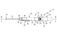
- the indwelling needle assembly 12 includes an indwelling needle 16 having a needle tip 14 and a needle tip protector 10 through which the indwelling needle 16 is movably inserted in the needle axis direction.
- the indwelling needle 16 is inserted into a patient's blood vessel.
- an external conduit 18 such as a cannula connected to the proximal end side of the indwelling needle assembly 12.
- the indwelling needle 16 After the indwelling needle 16 is used, the indwelling needle 16 is removed from the patient's blood vessel, and the needle tip protector 10 is moved toward the needle tip 14 so that the needle tip 14 of the indwelling needle 16 is moved by the needle tip protector 10. Covered and protected.
- the distal end side or the front side refers to the left side in FIG. 1 that is the needle tip 14 side of the indwelling needle 16, while the proximal end side or the rear side refers to the rear side in the puncture direction of the indwelling needle 16.
- the indwelling needle assembly 12 is configured by extrapolating and attaching the needle tip protector 10 to the needle unit 20 including the indwelling needle 16.
- the needle unit 20 includes an indwelling needle 16 and a needle hub 22 that fixes and supports the proximal end side of the indwelling needle 16.
- the indwelling needle 16 is a metal hollow needle, for example, and is formed of stainless steel or the like.
- the needle tip 14 of the indwelling needle 16 is tapered and has a sharp shape.
- a through-hole 24 is formed in the needle tip 14 of the indwelling needle 16 so that blood can easily flow into the indwelling needle 16.
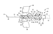
- the needle hub 22 has a substantially cylindrical needle hub body 26 and a support portion 28 that fixes and supports the needle hub body 26 in the direction of the needle axis of the indwelling needle 16 (left-right direction in FIG. 1).
- the structure is connected to each other.
- the needle hub main body 26 has a cylindrical shape with a substantially constant inner diameter dimension as a whole, and is formed of, for example, a hard synthetic resin.
- the inner diameter of the needle hub main body 26 at the distal end opening is substantially equal to the outer diameter of the indwelling needle 16, while the inner peripheral surface of the needle hub main body 26 protrudes to the inner peripheral side.
- An annular positioning projection 30 is provided.
- the proximal end side of the indwelling needle 16 is inserted from the distal end side opening of the needle hub body 26, and the proximal end of the indwelling needle 16 and the positioning projection 30 are in contact with each other, whereby the proximal end of the indwelling needle 16 is positioned. It has come to be.
- the needle hub body 26 and the indwelling needle 16 are bonded, so that the indwelling needle 16 is fixedly supported at the tip of the needle hub body 26.
- the outer diameter of the needle hub body 26 is different in the needle axis direction. That is, a small-diameter cylindrical portion 32 having an outer diameter dimension smaller than that of the proximal end portion is provided at an axially intermediate portion of the needle hub body 26.
- the outer peripheral surface of the needle hub body 26 on the distal end side with respect to the small diameter cylindrical portion 32 is a tapered surface 34 whose outer diameter dimension gradually increases toward the distal end side.
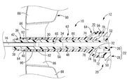
- annular locking recess 36 that opens to the outer peripheral side is formed.
- the locking recess 36 has a predetermined width dimension (dimension in the needle axis direction), and the minimum outer diameter of the needle hub body 26 at the position where the locking recess 36 is formed is the outer diameter of the small diameter cylindrical portion 32. It is approximately equal to the dimensions.
- annular locking projection 38 protruding to the outer peripheral side is formed. The outer diameter of the locking projection 38 is larger than the maximum outer diameter of the tip of the tapered surface 34.
- the base end side surface constituting the inner surface of the locking recess 36 is an annular base end side regulating surface 40 as a third locking portion extending in a direction perpendicular to the axis with a predetermined dimension A (see FIG. 9).
- the bottom surface of the locking recess 36 and the tapered surface 34 are continued in a step shape by the base end side regulating surface 40.
- the side surface of the tip constituting the inner surface of the locking recess 36 is an annular tip-side regulating surface 42 as a fourth locking portion that spreads in the direction perpendicular to the axis with a predetermined dimension B (see FIG. 9).
- the bottom surface of the retaining recess 36 and the outer peripheral surface of the locking projection 38 are continuous in a stepped shape by the front end side regulation surface 42.
- the dimension A in the direction perpendicular to the axis of the base end side regulating surface 40 constituted by the base end side inner surface of the locking recess 36 is larger than the dimension B in the direction perpendicular to the axis of the distal end side regulating surface 42. It is slightly larger.
- the support portion 28 as a whole has a substantially cylindrical shape with a step formed on the inner peripheral surface, and is formed of, for example, a hard synthetic resin, like the needle hub body 26. That is, the distal end side is a connecting cylinder portion 44 having a small inner diameter dimension, and the proximal end side is a connecting cylinder portion 46 having a large inner diameter dimension. Then, the proximal end of the needle hub body 26 is inserted into the connecting tube portion 44 and bonded or welded as necessary, thereby connecting the needle hub body 26 and the support portion 28 to each other.
- a fluid flow path 48 extending from the blood vessel to the external conduit 18 is constituted by the inner holes of the indwelling needle 16 and the needle hub 22 (the needle hub body 26 and the support portion 28).
- a pair of engaging arms 50 and 50 projecting toward the distal end side with a predetermined width dimension are integrally formed on both sides in one radial direction (upper and lower sides in FIG. 1) at the outer peripheral edge of the connecting tube portion 46. Is formed.
- the engaging arms 50 and 50 have a substantially rectangular shape in plan view, and have a plate thickness dimension (vertical dimension in FIG. 1) and a width dimension (base dimension in FIG. 1) at the base end portion (connection portion with the connecting tube portion 46).
- the vertical dimension in FIG. 2 is thin, and slit-shaped gaps 52, 52 are formed between the connecting cylinder portion 44 and the engagement arms 50, 50 in the plate thickness direction. It can be elastically deformed. Further, hooks 56, 56 projecting to the outer peripheral side are formed at the tip portions of the engaging arms 50, 50.
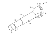
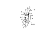
- the needle tip protector 10 has a substantially cylindrical shape extending in the needle axis direction as a whole, and is made of a hard material such as polypropylene, polycarbonate, glycol-modified polyethylene terephthalate, ABS resin, or the like. It is integrally formed of synthetic resin. That is, the needle tip protector 10 includes a cylindrical peripheral wall 58 and an inner hole 60 penetrating the inside of the peripheral wall 58 in the needle axis direction.
- the needle tip protector 10 (peripheral wall 58) has a different shape in the needle axis direction, the distal end side is a cylindrical portion 62 having a substantially circular ring cross section, and the proximal end side is a cylinder.
- the diameter-enlarged portion 64 is a larger-diameter portion than the shape-like portion 62 and spreads to the outer periphery. That is, the peripheral wall 58 of the needle tip protector 10 is configured to include the peripheral wall of the cylindrical portion 62 and the peripheral wall of the enlarged diameter portion 64, and the inner peripheral surface 65 of the peripheral wall 58 is the inner wall of the cylindrical portion 62.
- the peripheral surface and the inner peripheral surface of the peripheral wall of the enlarged diameter portion 64 are configured.
- the enlarged diameter portion 64 has a substantially elliptic cylindrical shape, and has a larger diameter in FIG. 6 than the width of the outer peripheral surface in the left-right direction, which is the small diameter direction in FIG. 6.
- the width dimension of the outer peripheral surface in the vertical direction, which is the direction, is made larger. That is, among the wall parts constituting the enlarged diameter part 64, the parts constituting the left and right wall parts in FIG. 6 are the small diameter parts 66, 66, while the vertical wall parts in FIG.
- the large diameter portions 68 and 68 are the portions where the small diameter portions 66 and 66 are opposed to each other, and the opposing directions of the small diameter portions 66 and 66 are orthogonal to each other.
- the outer diameter of the large diameter portions 68 and 68 is gradually increased from the distal end side to the proximal end side, and from the outer peripheral surface of the cylindrical portion 62 to the outer peripheral surface of the large diameter portions 68 and 68. Are connected by a smooth curved surface. Further, the thickness dimension from the cylindrical portion 62 to the large diameter portions 68, 68 is substantially constant in the needle axis direction, and is smaller than the thickness dimensions of the small diameter portions 66, 66. As a result, the inside of the enlarged diameter portion 64 has a cross-sectional shape that is substantially oval with the vertical dimension in FIG. 6 larger than the horizontal dimension in FIG. An inner space 70 in which the vertical dimension in FIG. 6 gradually increases is formed on the proximal end side of the inner hole 60 that penetrates the needle tip protector 10.
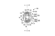
- the large-diameter portions 68 and 68 are formed with penetrating windows 72 and 72 as needle hub engaging portions penetrating in the plate thickness direction and extending with a predetermined circumferential dimension.
- the circumferential dimension of the through windows 72 and 72 is made larger than the circumferential dimension of the hooks 56 and 56.
- a pair of locking pieces 74, 74 as a pair of locking portions protruding inward are integrally formed from the inner peripheral surface 65 of the peripheral wall 58. These locking pieces 74, 74 are opposed to each other in positions corresponding to the large diameter portions 68, 68 in the large diameter portions 68, 68 in the enlarged diameter portion 64, that is, in the vertical direction in FIG. At a distance from each other).
- an annular stepped surface 76 having a predetermined dimension C (see FIG. 9) and extending in the direction perpendicular to the axis is formed on the inner peripheral surface 65 of the peripheral wall 58 at the front end portion of the enlarged diameter portion 64.
- the distal end side of the surface 76 has a larger diameter than the proximal end side.
- the stepped surface 76 is widened toward the outer periphery toward the front.
- the dimension C in the direction perpendicular to the axis of the stepped surface 76 is made smaller than the dimension B in the direction perpendicular to the axis of the front end side regulation surface 42 of the locking recess 36.
- locking pieces 74 are formed so as to protrude from the stepped surface 76 toward the proximal end side of the peripheral wall 58 on the proximal side of the stepped surface 76.
- the locking pieces 74, 74 extend from the stepped surface 76 toward the base end side substantially in parallel with the needle axis direction and are curved in the circumferential direction, respectively, and projecting tips (needle axis direction).
- Locking claws 78 and 78 that are bent toward the inner periphery are formed on the base end.
- the inner peripheral surfaces of these locking claws 78 and 78 are respectively curved in the circumferential direction, and the radius of curvature of the inner peripheral surfaces of the locking claws 78 and 78 is the outer diameter of the small diameter cylindrical portion 32 in the needle hub body 26. It is almost equal to the radius. Further, the distance between the opposing surfaces in the radial direction on the inner peripheral surfaces of the locking claws 78, 78 is substantially equal to the outer diameter of the small diameter cylindrical portion 32, while the maximum outer diameter of the tip portion of the tapered surface 34. It is smaller than the dimensions. However, the distance between the opposing surfaces in the radial direction on the inner peripheral surfaces of the locking claws 78, 78 may be slightly smaller than the outer diameter of the small-diameter cylindrical portion 32 or may be slightly larger. Good.
- the base end side end surfaces (protruding front end surfaces) 79 and 79 of the locking claws 78 and 78 are vertical surfaces 79a and 79a whose inner peripheral side extends in a direction perpendicular to the axis with a predetermined dimension D (see FIG. 9).
- the outer peripheral side is inclined surfaces 79b and 79b that incline toward the distal end as the outer peripheral side is reached.
- the dimension D in the direction perpendicular to the axis of the vertical surfaces 79a, 79a is substantially the same as or slightly larger than the dimension A in the direction perpendicular to the axis of the base end side regulating surface 40 of the locking recess 36.
- the locking claws 78, 78 abut on the proximal end regulating surface 40 and move toward the distal end side of the needle unit 20 (movement of the needle tip protector 10 toward the proximal end side in the needle axial direction). Is restricted, the entire base end side regulating surface 40 comes into contact with the vertical surfaces 79a and 79a, and a sufficiently large contact area can be secured. Furthermore, since the inclined surfaces 79b and 79b located on the outer peripheral side of the vertical surfaces 79a and 79a are inclined to the distal end side as they become the outer peripheral side, the vertical surfaces 79a and 79a and the base end side regulating surface 40 are formed. It can abut against the inclined surfaces 79b, 79b without interference, and the effect of preventing relative movement in the axial direction between the needle unit 20 and the needle tip protector 10 can be more reliably exhibited.
- the protruding tips (locking claws 78, 78) of the locking pieces 74, 74 are located on the tip side of the base end of the enlarged diameter portion 64. That is, the entire locking pieces 74 are provided in the accommodated state in the internal space 70 of the enlarged diameter portion 64.
- a wing-like portion 80 is provided at the tip portion of the needle tip protector 10. That is, the distal end portion of the cylindrical portion 62 is a small-diameter cylindrical portion 82 having a smaller diameter than the other portions, and a plurality of protrusions projecting outward from the outer peripheral surface of the small-diameter cylindrical portion 82. Article 84 is formed. And the fitting cylinder part 90 provided with a pair of wing
- the indwelling needle assembly 12 is configured by inserting the needle unit 20 through the proximal end side opening in the inner hole 60 of the needle tip protector 10 having the above-described structure.
- the needle tip 14 of the indwelling needle 16 is located on the tip side of the needle tip protector 10, and the needle tip 14 is exposed. Yes.
- the hooks 56 and 56 of the engaging arms 50 and 50 provided on the needle hub 22 enter and are locked into the through windows 72 and 72 provided on the enlarged diameter portion 64 of the needle tip protector 10.
- the needle tip protector 10 and the needle hub 22 are connected, and the protruding state of the needle tip 14 is maintained.
- the locking claws 78 of the needle tip protector 10 are in contact with the outer peripheral surface of the small diameter cylindrical portion 32 of the needle hub body 26.
- the locking claws 78, 78 may be slightly pressed to the outer peripheral side by contacting the outer peripheral surface of the small diameter cylindrical portion 32, or slightly separated from the outer peripheral surface of the small diameter cylindrical portion 32. It may be.
- the indwelling needle assembly 12 having such a structure is used for infusion, blood collection, and hemodialysis through the fluid flow channel 48 by puncturing and placing the indwelling needle 16 in the blood vessel of the patient.
- the indwelling needle assembly 12 of the present embodiment since the wing-like portion 80 is provided, for example, the indwelling needle 16 can be punctured while grasping the wing-like portion 80. Further, when the indwelling needle 16 is indwelled in a puncture state, the indwelling needle 16 can be fixed with a wide contact area to the skin by fixing the tape at the position of the wing-shaped portion 80.
- the engagement arms 50 and 50 in the needle hub 22 are pressed inward with fingers while the needle tip protector 10 is tape-fixed in the wing-shaped portion 80. Accordingly, the hooks 56 and 56 and the through windows 72 and 72 are unlocked, and the needle unit 20 can be moved to the proximal end side with respect to the needle tip protector 10. Further, the needle unit protector 10 is moved toward the needle tip 14 of the needle unit 20 by moving the needle unit 20 toward the proximal end with respect to the needle tip protector 10 and removing the indwelling needle 16 from the skin.
- the locking claws 78 Since the outer peripheral surface on the distal end side of the small diameter cylindrical portion 32 with which 78 abuts is a tapered surface 34 whose outer diameter dimension gradually increases toward the distal end side, the needle unit 20 is attached to the needle tip protector 10. The needle unit 20 is prevented from moving unless an external force for moving it to the proximal side is applied. Thereby, the malfunction that the needle tip 14 of the indwelling needle 16 is protected by the needle tip protector 10 unintentionally can be prevented.
- the locking pieces 74, 74 are pressed toward the outer peripheral side by the tapered surface 34 of the needle hub body 26, and the locking claw 78. 78 are slid against the tapered surface 34.
- an elastic restoring force toward the inner peripheral side is exerted on the locking pieces 74 and 74 as an urging force. Therefore, the pressing force applied to the tapered surfaces 34 of the locking claws 78 and 78 becomes resistance, and the needle unit is confirmed while the user is pulling the needle unit 20 against the needle tip protector 10. 20 can be moved.
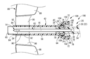
- the indwelling needle is moved by moving the needle unit 20 backward with respect to the needle tip protector 10 (moving the needle tip protector 10 forward toward the needle tip 14 of the needle unit 20).
- the 16 needle tips 14 are covered with the needle tip protector 10, and the locking claws 78, 78 of the locking pieces 74, 74 get over the tapered surface 34 of the needle hub body 26 and elastically return to the locking recess 36. It is supposed to go inside. In this state, the vertical surfaces 79a and 79a of the locking claws 78 and 78 are in contact with the proximal-side regulating surface 40 of the locking recess 36 (the locking claws 78 and 78 are locked to the proximal-side regulating surface 40).
- the stepped surface 76 provided at the front end portion of the locking pieces 74, 74 abuts on the tip side regulating surface 42 of the locking recess 36 (the stepped surface 76 is locked to the tip side regulating surface 42. Therefore, the movement of the needle unit 20 toward the proximal end side is restricted. This prevents the indwelling needle 16 from being pulled out to the proximal end side of the needle tip protector 10. Therefore, the movement of the needle unit 20 to both sides in the axial direction with respect to the needle tip protector 10 is prevented, and the protection state of the needle tip 14 of the indwelling needle 16 by the needle tip protector 10 is maintained.
- the locking claws 78, 78 provided on the free end side of the locking pieces 74, 74 are the first locking portions that prevent re-exposure of the needle tip 14 of the indwelling needle 16. Yes.
- the stepped surface 76 that integrally supports the fixed end sides of the locking pieces 74, 74 is a second locking portion that prevents the needle unit 20 from being pulled out from the proximal end side of the needle tip protector 10. ing.
- locking part (locking claw 78 and 78) have the vertical surfaces 79a and 79a as a 1st axis
- the locking part (stepped surface 76) is a second axis facing the axis extending in the direction perpendicular to the axis.
- the base end side surface (base end side regulating surface 40) is the third locking portion and faces the third axis extending in the direction perpendicular to the axis
- the tip side surface (tip end)
- the needle tip protector 10 since a pair of locking portions (locking pieces 74, 74) are provided, it is also compatible with the locking portion being integrally formed on the peripheral wall 58 of the needle tip protector 10.
- the needle tip protector 10 is more reliably prevented from retracting toward the proximal end side of the indwelling needle 16, and the needle tip The re-exposure preventing effect can be exhibited more stably.
- the plurality of locking portions are preferably provided substantially symmetrically with respect to the central axis of the needle tip protector 10.
- the tape fixing in the wing 80 is released, and the indwelling needle assembly 12 is removed from the patient. According to this removal procedure, since the needle tip 14 is not exposed at all from the puncture to the disposal of the indwelling needle 16, erroneous puncture or the like can be prevented more reliably.
- the procedure for protecting the needle tip 14 is not limited to the above procedure. After the tape fixing in the wing-shaped portion 80 is released and the indwelling needle 16 is removed from the blood vessel, the needle unit 20 is attached to the needle tip protector 10. The needle tip 14 of the indwelling needle 16 may be protected by moving backward.
- the tips of the locking claws 78, 78 come into contact with the bottom surface of the locking recess 36, so that the impact and sound of the contact are received by the user.
- the possibility of interrupting the pulling-out operation of the needle unit 20 in the middle is avoided. Thereby, protection of the needle tip 14 of the indwelling needle 16 by the needle tip protector 10 can be realized more reliably.
- the locking pieces 74 and 74 for preventing the re-exposure of the needle tip 14 of the indwelling needle 16 are provided inside the cylindrical peripheral wall 58, in particular. Since the entirety is accommodated and provided, it is substantially impossible to contact the locking pieces 74 and 74 from outside without intention. Therefore, in the state in which the needle tip 14 of the indwelling needle 16 is protected by the needle tip protector 10, the locking of the locking pieces 74, 74 and the locking recess 36 is unintentionally released and the needle tip 14 of the indwelling needle 16 is moved. Re-exposure from the needle tip protector 10 can be effectively prevented.
- the locking pieces 74 and 74 are provided on the enlarged diameter portion 64 which is expanded on the proximal end side of the needle tip protector 10. Accordingly, the needle hub 22 (needle hub body 26) inserted between the locking pieces 74 and 74 has a sufficiently large outer diameter while ensuring a sufficient size of the locking pieces 74 and 74. Can be done. Furthermore, in the present embodiment, the enlarged diameter portion 64 is substantially elliptical, and the outer peripheral surface thereof is smoothly continuous from the outer peripheral surface of the cylindrical portion 62. There is a reduced risk that the patient will feel pain in contact.
- the locking pieces 74 and 74 are provided inside the large diameter portions 68 and 68 constituting the substantially elliptical enlarged diameter portion 64, the space inside the large diameter portions 68 and 68 is skillfully formed.
- the large-diameter portions 68 and 68 can be prevented from becoming thick, and the occurrence of dimensional errors and deterioration of quality accuracy due to the mixing of bubbles into the member during molding can be suppressed.
- locking part (locking piece 74,74) is provided so that it may extend in the same direction (base end side of an axial direction) as the large diameter parts 68 and 68.
- the space inside the large diameter portions 68, 68 can be used skillfully, and the large diameter portions 68, 68 can be used. Is prevented from becoming thick, and it is possible to suppress the occurrence of dimensional errors and the deterioration of quality accuracy due to air bubbles mixed into the member during molding.
- the locking pieces 74 are provided so as to protrude into the peripheral wall 58, for example, when the needle tip protector 10 is manufactured by molding, the mold is removed in the needle axis direction of the needle tip protector 10. It is possible to mold, and the number of types of molds can be reduced. Therefore, the manufacturing efficiency of the needle tip protector 10 can be improved.
- the locking pieces 74 and 74 extend toward the proximal end side, they are not caught when the needle unit 20 is pulled out from the needle tip protector 10, and smooth pulling out can be realized.
- the protection state of the needle tip 14 of the indwelling needle 16 by the needle tip protector 10 that is, the locking pieces 74 and 74 are locked.
- the needle hub body 26 can be held between the radial directions by the locking pieces 74, 74. Therefore, the needle tip protector 10 and the needle unit 20 (needle hub body 26) do not wobble between the radial directions, and the protection state of the needle tip 14 of the indwelling needle 16 by the needle tip protector 10 is stably maintained. Can be done.
- the locking claws 78, 78 that are the first locking portions and the proximal end regulation surface 40 of the locking recess 36 that is the third locking portion abut each other.
- the needle tip protector 10 can be prevented from moving to the proximal end side with respect to the needle unit 20.
- the stepped surface 76 that is the second locking portion and the distal-end-side regulating surface 42 of the locking recess 36 that is the fourth locking portion abut each other, so that the needle tip protector 10 is against the needle unit 20. Can be prevented from moving to the tip side.
- each of the first to fourth locking portions has first to fourth shaft faces extending in a direction perpendicular to the axis, and therefore, there is no undercut shape and molding is easy.
- the contact reaction force can be efficiently generated as an axial force.
- each contact area can also be ensured sufficiently and the movement of the needle tip protector 10 toward the distal end side and the proximal end side with respect to the needle unit 20 can be more reliably prevented.
- FIGS. 10 and 11 show a needle tip protector 100 for an indwelling needle as a second embodiment of the present invention.
- the structure of the needle tip protector 100 of the present embodiment is substantially the same as that of the first embodiment.
- a deformation amount limiting portion 102 is provided for limiting the deformation amount of the locking pieces 74, 74 to the outer peripheral side.
- members and portions that are substantially the same as those in the first embodiment are denoted by the same reference numerals as those in the first embodiment in the drawing, and detailed description thereof is omitted. .
- deformation amount limiting portions 102 and 102 are provided between the peripheral wall 58 and the locking pieces 74 and 74 in the radial direction in the internal space 70 of the enlarged diameter portion 64.
- the deformation amount limiting portions 102, 102 projecting toward the proximal end are integrally formed on the inner peripheral surface 65 of the large diameter portion 68, 68 constituting the enlarged diameter portion 64. Is formed.
- the wall portions constituting the large-diameter portions 68 and 68 in the enlarged-diameter portion 64 are partially thickened, whereby the deformation amount limiting portions 102 and 102 are formed.
- the deformation amount limiting portions 102 and 102 gradually increase in the radial dimension (in FIG. 11) toward the proximal end side.
- the vertical dimension of the vertical cross section shown in FIG. 11 is substantially a right triangle.
- the inner peripheral surfaces of the deformation amount limiting portions 102, 102 extend substantially parallel to the locking pieces 74, 74 (that is, substantially parallel to the needle axis direction of the indwelling needle 16), while the proximal end surface is the indwelling needle. It spreads in a direction substantially orthogonal to the 16 needle axis directions.
- the base end surfaces of the deformation amount limiting portions 102 and 102 are located on the tip side in the needle axis direction with respect to the needle shaft direction base ends (protruding leading ends) of the locking pieces 74 and 74, and the deformation amount limiting portions 102 and 102 are located. Is housed in the internal space 70 of the enlarged diameter portion 64.
- each deformation amount limiting portion 102, 102 is composed of three protrusions 104, 104, 104 protruding from the inner peripheral surface 65 of the enlarged diameter portion 64 toward the proximal end side.
- These three protrusions 104, 104, 104 are circumferentially arranged between the wall portions (between the left and right directions in FIG. 10) constituting the small diameter portions 66, 66 which are thicker than the large diameter portions 68, 68.
- these three protrusions 104, 104, 104 are also in the radial direction (vertical direction in FIG. 10) of the locking piece 74, and protect the needle tip from the state before the needle tip protection (for example, see FIGS. 3 and 4). They are provided at an appropriate distance so as not to hinder the movement of the needle tip protector 100 to a state (for example, see FIGS. 7 and 8).
- the inner peripheral surface of the deformation amount limiting portion 102 including these three protrusions 104, 104, 104 has a curved shape substantially corresponding to the outer peripheral surface of the locking piece 74.
- the portions 104, 104, 104 and the locking piece 74 are separated by a substantially constant distance.
- the separation distance between the protrusions 104, 104, 104 and the locking piece 74 hinders deformation of the locking piece 74 toward the outer peripheral side when the needle unit 20 moves toward the distal end side with respect to the needle unit 20.
- the amount of deformation of the locking piece 74 abuts against the deformation amount limiting portion 102 (protrusions 104, 104, 104) when the indwelling needle assembly 106 is bent and deformed, as will be described later. Is set to a size regulated by
- the dimension E (see FIG. 13) in the direction perpendicular to the axis of the vertical surfaces 105a and 105a as the first axis faces on the base end side end surfaces 105 and 105 of the locking pieces 74 and 74 is It is smaller than the dimension A in the direction perpendicular to the axis at the base end side regulating surface 40 (facing the third axis) of the recess 36.
- the outer peripheral end ⁇ of the vertical surface 105a of the locking piece 74 is positioned on the inner peripheral side of the outer peripheral end ⁇ of the proximal-side regulating surface 40 of the locking recess 36, and this is applied.
- the indwelling needle tip protector 100 having such a structure is extrapolated to the needle unit 20 having the same structure as that of the first embodiment, so that the indwelling needle assembly 106 (FIG. 12). Then, as in the first embodiment, the indwelling needle assembly 106 is punctured, and after the puncture, the needle tip protector 100 is moved to the needle tip 14 side of the indwelling needle 16 as shown in FIGS. By moving the needle tip protector 100, the needle tip 14 of the indwelling needle 16 is protected. That is, the locking claws 78, 78 provided at the distal ends of the locking pieces 74, 74 enter the locking recess 36 provided at the distal end portion of the needle hub body 26 and are locked.
- the deformation amount limiting portions 102, 102 are provided on the outer peripheral side of the locking pieces 74, 74, the locking claw 78 of the locking claw 78 is protected in the protected state of the needle tip 14 of the indwelling needle 16. Unintentional detachment from the locking recess 36 can be effectively prevented. Specifically, for example, under the protection state of the needle tip 14, an external force in the bending direction is applied to the entire needle tip protector 100 and the needle unit 20, and one locking piece 74 is pushed by the needle hub body 26. When greatly deformed outward, the locking claw 78 of the other locking piece 74 floats outward from the base end side regulation surface 40, and the locked state is released or the locking piece 74 is damaged.
- indwelling needle tip protector 100 and indwelling needle assembly 106 of the present embodiment the same effects as in the first embodiment can be exhibited.
- the deformation amount limiting portions 102 and 102 are provided on the inner peripheral side of the large diameter portions 68 and 68 in the large diameter portion 64, and the internal space 70 of the large diameter portion 64 can be used skillfully.
- an increase in the size of the needle tip protector 100 accompanying the provision of a deformation amount limiting mechanism for the locking pieces 74, 74 can be avoided.
- the dimension E in the direction perpendicular to the axis of the vertical surfaces 105 a and 105 a is the axis on the base end side regulating surface 40 of the locking recess 36.
- the outer end ⁇ of the vertical surface 105 a of the locking piece 74 is brought into contact with the base-side regulating surface 40 by being smaller than the dimension A in the perpendicular direction.
- the vertical surface 105a that contacts the base end side regulating surface 40 in the locking claw 78 is biased toward the inner peripheral side from the central axis of the locking piece 74, so that the bending moment due to the contact reaction force acts.
- the locking piece 74 may be deformed into a curved shape that protrudes outward, and the vertical surface 105a of the locking claw 78 may be inclined. In the inclined state of the vertical surface 105a, when the end portion ⁇ of the vertical surface 105a is positioned on the outer peripheral side from the end portion ⁇ of the base end side regulating surface 40, the end portion ⁇ of the base end side regulating surface 40 is inclined.
- the locking pieces 74 and 74 extend toward the proximal end side, but may extend toward the distal end side.
- the entire locking pieces 74, 74 are accommodated inside the peripheral wall 58.
- the front end of the locking portion is located outward from the end in the needle axis direction of the peripheral wall. It may be.
- the substantial latching part (for example, latching claw 78, 78 in the said embodiment) in a latching part does not need to be provided in the front-end
- the inner peripheral side is the vertical surfaces 79a and 79a (105a and 105), while the outer peripheral side is inclined.
- the surface 79b, 79b (105b, 105b) it is not limited to this aspect. That is, the base end side end surfaces 79 and 79 (105 and 105) of the locking pieces 74 and 74 are spread in the direction perpendicular to the axis over substantially the entire surface without the inclined surfaces 79b and 79b (105b and 105b).
- the vertical surfaces 79a and 79a may be provided in a direction inclined with respect to the axial direction over substantially the entire surface.
- the inclined surfaces 79b and 79b may be inclined toward the distal end side toward the outer peripheral side as in the above embodiment, or the vertical surfaces 79a and 79a (105a and 105a) and the proximal end side. As long as it does not interfere with the contact with the restricting surface 40, it may be inclined toward the base end as it becomes the outer peripheral side.
- the inner peripheral side portion of the base end side end surfaces 79, 79 (105, 105) of the locking pieces 74, 74 and the base end side regulating surface 40 of the needle hub main body 26 are replaced with a vertical surface as shown in the example. It is also possible to make the inclined surface inclined toward the distal end side as it goes to the side, whereby the proximal side regulating surface 40 becomes an undercut having an overhang shape, but it is also possible to obtain a larger movement regulating force become.
- the pair of locking pieces 74 and 74 are provided to face each other in the radial direction.
- the number of the locking portions may be one, or may be three or more. In this case, it is preferable that three or more locking portions are provided at substantially equal intervals in the circumferential direction. Or you may be set as the substantially cylindrical latching
- the latching recessed part provided in a needle hub main body does not need to be provided continuously over the perimeter, and should just be provided in the position corresponding to a latching part in the circumferential direction.
- the stepped surface 76 provided on the fixed end side of the locking pieces 74, 74 in the needle tip protector 10, 100, and the tip side regulating surface provided on the needle hub 22 (needle hub body 26). 42 is prevented from being pulled out from the proximal end side of the needle unit 20 from the needle tip protectors 10, 100, but the mechanism for preventing the needle unit from being pulled out is limited to such a mode. is not. That is, the stepped surface 76 and the front end side regulating surface 42 are not essential, and a needle unit extraction preventing mechanism may be provided separately from these.
- the stepped surface 76, the base end side regulating surface 40, the distal end side regulating surface 42, etc. spread in the direction perpendicular to the axis, but these may be inclined and spread with respect to the direction perpendicular to the axis. Good.
- the base end side of the needle point protectors 10 and 100 was made into the cylindrical part 62 which has an annular cross section
- the base end side was made into the enlarged diameter part 64 of elliptical cylinder shape, but these shapes It is not limited to. That is, various shapes such as a circular shape (including an ellipse, an ellipse, a semicircle, and the like) and a polygonal shape can be adopted as the cross-sectional shapes at the distal end side and proximal end side expanded portions of the needle tip protector.
- the widened portion provided on the proximal end side of the needle tip protector is not essential, and the needle tip protector may be a simple straight tube shape.
- the shape of the needle unit is not limited.
- the needle hub 22 and the needle tip protectors 10 and 100 are connected, that is, the hooks 56 and 56 are locked to the through windows 72 and 72 to maintain the indwelling needle 16 in an exposed state.
- the present invention is not limited to such an embodiment. That is, the needle hub engaging portion does not need to have a through window shape as in the above-described embodiment, and may have a bottomed groove shape that opens to the inner peripheral side.
- a hook as a needle hub engaging portion may be formed on the needle tip protector, and a penetrating window or a bottomed groove may be formed on the needle hub.
- these hooks and through windows are not essential, and in short, a connection mechanism between the needle hub and the needle tip protector before use is not essential.
- the wing-shaped portion 80 is attached to the needle tip protectors 10, 100, but the wing-shaped portion is not essential.
- the deformation amount limiting portions 102 and 102 are integrally formed with the enlarged-diameter portion 64 of the needle tip protector 100, but may be formed separately and later fixed. Thereby, for example, the deformation amount limiting portion can be formed of a material different from that of the needle tip protector.
- the deformation amount limiting portions 102, 102 are provided on the inner peripheral surface 65 of the wall portion constituting the large diameter portions 68, 68 in the enlarged diameter portion 64.
- the formation position of the limiting portion is not limited at all. That is, the deformation amount limiting portion is provided so as to protrude from the inner peripheral surface of the wall portion constituting the small diameter portion in the enlarged diameter portion toward the outer peripheral side of the locking portions (locking pieces 74, 74), for example. May be.
- the deformation amount limiting portion is not limited to the aspect provided on the inner peripheral surface of the enlarged diameter portion.
- the deformation amount limiting portion is provided on the outer peripheral surface of the locking portion and is elastically deformed toward the outer peripheral side of the locking portion. The deformation may be limited by contacting the inner peripheral surface of the enlarged diameter portion.
- the shape of the deformation amount limiting portion is not limited at all.
- the deformation amount limiting portions 102, 102 have a substantially right-angled triangular longitudinal section, but, for example, a protrusion protruding from the inner peripheral surface of the enlarged diameter portion to the proximal end side or the inner peripheral side. It may be in the form of a piece, or may be in the form of a protruding piece that protrudes from the outer peripheral surface of the locking portion (locking pieces 74, 74) to the outer peripheral side.
- the deformation amount limiting portions 102, 102 are each composed of the three protrusions 104, 104, 104, but the present invention is not limited to this mode, and one or two of them are not limited. You may be comprised from four or more protrusions.
- the deformation amount limiting portions 102 and 102 by configuring the deformation amount limiting portions 102 and 102 with a plurality of protrusions in this way, it is possible to reduce the sink time (deformation due to thermal shrinkage) after molding and shorten the molding time associated with improving cooling efficiency. .
- the two locking pieces 74, 74 are provided, and the deformation amount limiting portions 102, 102 are provided on the outer peripheral side of the respective locking pieces 74, 74.
- the deformation amount limiting portion may be provided only on the outer peripheral side of any one of the locking portions (locking pieces 74).
- Needle tip protector for indwelling needle 12, 106: Indwelling needle assembly, 14: Needle tip, 16: Indwelling needle, 22: Needle hub, 40: Proximal-side regulating surface (third locking portion, Triaxial face), 42: Tip side regulating surface (fourth locking part, fourth axis face), 58: peripheral wall, 64: diameter-expanded part (expanded part), 66: small-diameter part, 68: large-diameter part, 72: penetrating window (needle hub engaging portion), 74: locking piece (locking portion), 76: stepped surface (second locking portion, facing the second shaft), 78: locking claw (first locking) 79), 105: base end side end surface, 79a, 105a: vertical surface (facing the first axis), 102: deformation amount limiting portion
Abstract
La présente invention concerne un dispositif de protection de pointe d'aiguille d'une nouvelle structure pour une aiguille à demeure, qui permet d'améliorer la sécurité, etc. par rapport à des dispositifs de protection de pointe d'aiguille classiques. Le dispositif de protection de pointe d'aiguille (10) pour une aiguille à demeure selon la présente invention est pourvu d'une paroi périphérique tubulaire (58) et est fixé à l'extérieur sur un raccord d'aiguille (22) d'une aiguille à demeure (16) et déplacé vers un côté pointe d'aiguille (14) de sorte à recouvrir la pointe d'aiguille (14) de l'aiguille à demeure (16). Des parties de mise en prise (74, 74), qui doivent venir en prise avec le raccord d'aiguille (22) à une position atteinte lorsqu'elles sont déplacées vers le côté pointe d'aiguille (14) de l'aiguille à demeure (16) de sorte à empêcher le retrait de l'aiguille à demeure (16) vers le côté extrémité de base (5) et à empêcher une nouvelle exposition de la pointe d'aiguille (14), sont formées dans l'espace intérieur entouré par la paroi périphérique tubulaire (58) et sont moulées d'un seul tenant avec la paroi périphérique tubulaire (58).
Priority Applications (5)
| Application Number | Priority Date | Filing Date | Title |
|---|---|---|---|
| JP2018521150A JP6911846B2 (ja) | 2016-06-03 | 2017-06-02 | 留置針用針先プロテクタおよび留置針組立体 |
| EP20193695.2A EP3766532A1 (fr) | 2016-06-03 | 2017-06-02 | Dispositif de protection de pointe d'aiguille pour une aiguille à demeure et ensemble aiguille à demeure |
| CN201780034358.8A CN109562224B (zh) | 2016-06-03 | 2017-06-02 | 留置针用针尖保护器以及留置针组件 |
| EP17806854.0A EP3466464B1 (fr) | 2016-06-03 | 2017-06-02 | Dispositif de protection de pointe d'aiguille pour une aiguille à demeure et ensemble aiguille à demeure |
| US16/306,624 US11331454B2 (en) | 2016-06-03 | 2017-06-02 | Needle tip protector for indwelling needle and indwelling needle assembly |
Applications Claiming Priority (2)
| Application Number | Priority Date | Filing Date | Title |
|---|---|---|---|
| JP2016-112071 | 2016-06-03 | ||
| JP2016112071 | 2016-06-03 |
Publications (1)
| Publication Number | Publication Date |
|---|---|
| WO2017209304A1 true WO2017209304A1 (fr) | 2017-12-07 |
Family
ID=60477660
Family Applications (1)
| Application Number | Title | Priority Date | Filing Date |
|---|---|---|---|
| PCT/JP2017/020720 WO2017209304A1 (fr) | 2016-06-03 | 2017-06-02 | Dispositif de protection de pointe d'aiguille pour une aiguille à demeure et ensemble aiguille à demeure |
Country Status (5)
| Country | Link |
|---|---|
| US (1) | US11331454B2 (fr) |
| EP (2) | EP3466464B1 (fr) |
| JP (7) | JP6911846B2 (fr) |
| CN (2) | CN109562224B (fr) |
| WO (1) | WO2017209304A1 (fr) |
Cited By (1)
| Publication number | Priority date | Publication date | Assignee | Title |
|---|---|---|---|---|
| WO2021029393A1 (fr) * | 2019-08-09 | 2021-02-18 | ニプロ株式会社 | Protecteur de pointe d'aiguille et corps assemblé d'aiguille l'utilisant |
Families Citing this family (5)
| Publication number | Priority date | Publication date | Assignee | Title |
|---|---|---|---|---|
| WO2021060053A1 (fr) * | 2019-09-24 | 2021-04-01 | テルモ株式会社 | Aiguille médicale et procédé de fabrication d'aiguille médicale |
| EP4197573A1 (fr) | 2020-08-14 | 2023-06-21 | Nipro Corporation | Ensemble aiguille à ailettes, matériau de conditionnement pour ensemble aiguille à ailettes, capuchon pour ensemble aiguille à ailettes, et jeu d'ensemble aiguille à ailettes |
| EP4245333A4 (fr) * | 2020-11-18 | 2023-12-27 | TERUMO Kabushiki Kaisha | Aiguille à demeure |
| DE102021115548A1 (de) | 2021-06-16 | 2022-12-22 | Sarstedt Ag & Co. Kg | Sicherheitskanülenanordnung |
| DE102021115561A1 (de) | 2021-06-16 | 2022-12-22 | Sarstedt Ag & Co. Kg | Sicherheitskanülenanordnung |
Citations (5)
| Publication number | Priority date | Publication date | Assignee | Title |
|---|---|---|---|---|
| JP3134920B2 (ja) | 1996-09-20 | 2001-02-13 | 株式会社ニッショー | 翼付留置針 |
| US20040236287A1 (en) * | 2003-05-23 | 2004-11-25 | Becton Dickinson & Company | Forward shielding medical needle device |
| US20070260190A1 (en) * | 2006-05-02 | 2007-11-08 | Hui-Chiang Lin | Safety device for intravenous injection unit |
| JP2008029812A (ja) * | 2006-06-30 | 2008-02-14 | Nipro Corp | 翼付留置針 |
| JP2013192738A (ja) * | 2012-03-21 | 2013-09-30 | Terumo Corp | 医療用針 |
Family Cites Families (19)
| Publication number | Priority date | Publication date | Assignee | Title |
|---|---|---|---|---|
| US5092851A (en) * | 1991-01-04 | 1992-03-03 | Ragner & Staab Associates | Safety needle with spring-loaded shield |
| JP3245843B2 (ja) * | 1994-01-21 | 2002-01-15 | ニプロ株式会社 | 翼付留置針 |
| JP2002345955A (ja) | 2001-05-23 | 2002-12-03 | Kazuaki Yamaoka | 安全キャップ付注射針 |
| US7018344B2 (en) | 2003-01-21 | 2006-03-28 | Becton, Dickinson And Company | Retractable needle shielding device |
| US7041066B2 (en) | 2003-03-13 | 2006-05-09 | Becton, Dickinson & Company | Needle assembly |
| US7037292B2 (en) * | 2003-06-27 | 2006-05-02 | Sherwood Services Ag | Safety needle shield apparatus |
| JP2006123645A (ja) * | 2004-10-27 | 2006-05-18 | Toyota Motor Corp | 電動パワーステアリング装置 |
| US20060135910A1 (en) * | 2004-12-17 | 2006-06-22 | Luther Ronald B | Percutaneous safety needle inserter |
| WO2006123645A1 (fr) * | 2005-05-19 | 2006-11-23 | Nipro Corporation | Ensemble a aiguille du type a ailettes |
| JP4807017B2 (ja) * | 2005-09-20 | 2011-11-02 | トヨタ自動車株式会社 | 車両の操舵制御装置 |
| CN200951238Y (zh) * | 2005-12-21 | 2007-09-26 | 刘晗 | 一次性使用安全静脉输液针 |
| US20110071469A1 (en) * | 2007-08-13 | 2011-03-24 | Craig Douglas Wilson | Single Use Retractable Infusion or Transfusion Needle |
| JP2010187984A (ja) * | 2009-02-19 | 2010-09-02 | Jms Co Ltd | 医療用針装置 |
| JP5594520B2 (ja) * | 2010-06-04 | 2014-09-24 | 株式会社ジェイ・エム・エス | 留置針装置 |
| US10368790B2 (en) * | 2012-10-23 | 2019-08-06 | Poly Medicure Limited | Needle safety assembly |
| AT516045B1 (de) * | 2014-07-18 | 2016-02-15 | Greiner Bio One Gmbh | Sicherheitsnadelanordnung zur Entnahme von Flüssigkeit aus einem Körper |
| CN204219517U (zh) * | 2014-10-15 | 2015-03-25 | 江苏采纳医疗科技有限公司 | 自毁式安全医用针 |
| DE102015207792A1 (de) * | 2015-04-28 | 2016-11-03 | Henkel Ag & Co. Kgaa | Polyurethan-basiertes Bindemittel-System |
| JP6664270B2 (ja) * | 2016-04-26 | 2020-03-13 | 株式会社トップ | プロテクタ付き医療用針 |
-
2017
- 2017-06-02 CN CN201780034358.8A patent/CN109562224B/zh active Active
- 2017-06-02 EP EP17806854.0A patent/EP3466464B1/fr active Active
- 2017-06-02 US US16/306,624 patent/US11331454B2/en active Active
- 2017-06-02 JP JP2018521150A patent/JP6911846B2/ja active Active
- 2017-06-02 CN CN202110953668.8A patent/CN113663163A/zh active Pending
- 2017-06-02 EP EP20193695.2A patent/EP3766532A1/fr active Pending
- 2017-06-02 WO PCT/JP2017/020720 patent/WO2017209304A1/fr active Application Filing
-
2019
- 2019-04-26 JP JP2019086613A patent/JP6566159B2/ja active Active
- 2019-04-26 JP JP2019086623A patent/JP6566161B1/ja active Active
- 2019-04-26 JP JP2019086620A patent/JP6566160B1/ja active Active
-
2020
- 2020-01-20 JP JP2020007087A patent/JP6868202B2/ja active Active
-
2021
- 2021-07-06 JP JP2021111984A patent/JP7190118B2/ja active Active
- 2021-07-08 JP JP2021113777A patent/JP2021166771A/ja active Pending
Patent Citations (5)
| Publication number | Priority date | Publication date | Assignee | Title |
|---|---|---|---|---|
| JP3134920B2 (ja) | 1996-09-20 | 2001-02-13 | 株式会社ニッショー | 翼付留置針 |
| US20040236287A1 (en) * | 2003-05-23 | 2004-11-25 | Becton Dickinson & Company | Forward shielding medical needle device |
| US20070260190A1 (en) * | 2006-05-02 | 2007-11-08 | Hui-Chiang Lin | Safety device for intravenous injection unit |
| JP2008029812A (ja) * | 2006-06-30 | 2008-02-14 | Nipro Corp | 翼付留置針 |
| JP2013192738A (ja) * | 2012-03-21 | 2013-09-30 | Terumo Corp | 医療用針 |
Non-Patent Citations (1)
| Title |
|---|
| See also references of EP3466464A4 |
Cited By (1)
| Publication number | Priority date | Publication date | Assignee | Title |
|---|---|---|---|---|
| WO2021029393A1 (fr) * | 2019-08-09 | 2021-02-18 | ニプロ株式会社 | Protecteur de pointe d'aiguille et corps assemblé d'aiguille l'utilisant |
Also Published As
| Publication number | Publication date |
|---|---|
| JP2020062507A (ja) | 2020-04-23 |
| JP6868202B2 (ja) | 2021-05-12 |
| EP3766532A1 (fr) | 2021-01-20 |
| CN113663163A (zh) | 2021-11-19 |
| JP6911846B2 (ja) | 2021-07-28 |
| EP3466464A4 (fr) | 2019-04-10 |
| US11331454B2 (en) | 2022-05-17 |
| EP3466464A1 (fr) | 2019-04-10 |
| JP6566159B2 (ja) | 2019-08-28 |
| JP2021166754A (ja) | 2021-10-21 |
| EP3466464B1 (fr) | 2020-11-25 |
| JP2019171086A (ja) | 2019-10-10 |
| JP6566160B1 (ja) | 2019-08-28 |
| JP6566161B1 (ja) | 2019-08-28 |
| JP2021166771A (ja) | 2021-10-21 |
| CN109562224B (zh) | 2021-09-07 |
| JPWO2017209304A1 (ja) | 2019-03-28 |
| JP7190118B2 (ja) | 2022-12-15 |
| JP2019155123A (ja) | 2019-09-19 |
| JP2019115835A (ja) | 2019-07-18 |
| CN109562224A (zh) | 2019-04-02 |
| US20190160265A1 (en) | 2019-05-30 |
Similar Documents
| Publication | Publication Date | Title |
|---|---|---|
| JP6566161B1 (ja) | 留置針組立体 | |
| JP5321957B2 (ja) | 留置針組立体 | |
| WO2010038471A1 (fr) | Gaine de protection pour pointe d’aiguille et ensemble d’aiguilles à demeure | |
| EP2464408B1 (fr) | Instrument de cathéter | |
| JP6720155B2 (ja) | カテーテル組立体 | |
| JP3805433B2 (ja) | 自動式カニューレ先端ガード付き静脈カテーテルアセンブリ | |
| CA2553063C (fr) | Mecanisme de liberation de catheter a bec de canard | |
| EP2618874B1 (fr) | Dispositif de protection de pointe d'aiguille | |
| CA2553090A1 (fr) | Pince pour gaine d'aiguille avec palpeur | |
| JP2018507012A (ja) | 摩擦に基づく保持力および使用不可機能を持つ安全な静脈カテーテル | |
| WO2017051802A1 (fr) | Ensemble cathéter | |
| JP6616399B2 (ja) | カテーテル組立体 | |
| JP5136855B2 (ja) | 針先保護用プロテクタ及び留置針組立体 | |
| JP5322023B2 (ja) | 針先保護用プロテクタ及び留置針組立体 | |
| JP5259810B2 (ja) | ヒールを有したニードルガードクリップ | |
| WO2017115756A1 (fr) | Aiguille médicale fixée à un protecteur | |
| JP3746036B2 (ja) | 翼付留置針用プロテクタ | |
| JP6166358B2 (ja) | カテーテル組立体 | |
| JP2021058263A (ja) | 針組立体 | |
| JP2021037104A (ja) | 針組立体 |
Legal Events
| Date | Code | Title | Description |
|---|---|---|---|
| WWE | Wipo information: entry into national phase |
Ref document number: 2018521150 Country of ref document: JP |
|
| 121 | Ep: the epo has been informed by wipo that ep was designated in this application |
Ref document number: 17806854 Country of ref document: EP Kind code of ref document: A1 |
|
| NENP | Non-entry into the national phase |
Ref country code: DE |
|
| ENP | Entry into the national phase |
Ref document number: 2017806854 Country of ref document: EP Effective date: 20190103 |