WO2017209304A1 - Needlepoint protector for indwelling needle and indwelling needle assembly - Google Patents
Needlepoint protector for indwelling needle and indwelling needle assembly Download PDFInfo
- Publication number
- WO2017209304A1 WO2017209304A1 PCT/JP2017/020720 JP2017020720W WO2017209304A1 WO 2017209304 A1 WO2017209304 A1 WO 2017209304A1 JP 2017020720 W JP2017020720 W JP 2017020720W WO 2017209304 A1 WO2017209304 A1 WO 2017209304A1
- Authority
- WO
- WIPO (PCT)
- Prior art keywords
- needle
- locking
- indwelling
- needle tip
- peripheral wall
- Prior art date
Links
Images


Classifications
-
- A—HUMAN NECESSITIES
- A61—MEDICAL OR VETERINARY SCIENCE; HYGIENE
- A61M—DEVICES FOR INTRODUCING MEDIA INTO, OR ONTO, THE BODY; DEVICES FOR TRANSDUCING BODY MEDIA OR FOR TAKING MEDIA FROM THE BODY; DEVICES FOR PRODUCING OR ENDING SLEEP OR STUPOR
- A61M25/00—Catheters; Hollow probes
- A61M25/01—Introducing, guiding, advancing, emplacing or holding catheters
- A61M25/06—Body-piercing guide needles or the like
- A61M25/0612—Devices for protecting the needle; Devices to help insertion of the needle, e.g. wings or holders
- A61M25/0637—Butterfly or winged devices, e.g. for facilitating handling or for attachment to the skin
-
- A—HUMAN NECESSITIES
- A61—MEDICAL OR VETERINARY SCIENCE; HYGIENE
- A61M—DEVICES FOR INTRODUCING MEDIA INTO, OR ONTO, THE BODY; DEVICES FOR TRANSDUCING BODY MEDIA OR FOR TAKING MEDIA FROM THE BODY; DEVICES FOR PRODUCING OR ENDING SLEEP OR STUPOR
- A61M25/00—Catheters; Hollow probes
- A61M25/01—Introducing, guiding, advancing, emplacing or holding catheters
- A61M25/06—Body-piercing guide needles or the like
- A61M25/0612—Devices for protecting the needle; Devices to help insertion of the needle, e.g. wings or holders
- A61M25/0631—Devices for protecting the needle; Devices to help insertion of the needle, e.g. wings or holders having means for fully covering the needle after its withdrawal, e.g. needle being withdrawn inside the handle or a cover being advanced over the needle
-
- A—HUMAN NECESSITIES
- A61—MEDICAL OR VETERINARY SCIENCE; HYGIENE
- A61M—DEVICES FOR INTRODUCING MEDIA INTO, OR ONTO, THE BODY; DEVICES FOR TRANSDUCING BODY MEDIA OR FOR TAKING MEDIA FROM THE BODY; DEVICES FOR PRODUCING OR ENDING SLEEP OR STUPOR
- A61M5/00—Devices for bringing media into the body in a subcutaneous, intra-vascular or intramuscular way; Accessories therefor, e.g. filling or cleaning devices, arm-rests
- A61M5/14—Infusion devices, e.g. infusing by gravity; Blood infusion; Accessories therefor
- A61M5/158—Needles for infusions; Accessories therefor, e.g. for inserting infusion needles, or for holding them on the body
-
- A—HUMAN NECESSITIES
- A61—MEDICAL OR VETERINARY SCIENCE; HYGIENE
- A61M—DEVICES FOR INTRODUCING MEDIA INTO, OR ONTO, THE BODY; DEVICES FOR TRANSDUCING BODY MEDIA OR FOR TAKING MEDIA FROM THE BODY; DEVICES FOR PRODUCING OR ENDING SLEEP OR STUPOR
- A61M5/00—Devices for bringing media into the body in a subcutaneous, intra-vascular or intramuscular way; Accessories therefor, e.g. filling or cleaning devices, arm-rests
- A61M5/178—Syringes
- A61M5/31—Details
- A61M5/32—Needles; Details of needles pertaining to their connection with syringe or hub; Accessories for bringing the needle into, or holding the needle on, the body; Devices for protection of needles
- A61M5/3205—Apparatus for removing or disposing of used needles or syringes, e.g. containers; Means for protection against accidental injuries from used needles
- A61M5/321—Means for protection against accidental injuries by used needles
- A61M5/3243—Means for protection against accidental injuries by used needles being axially-extensible, e.g. protective sleeves coaxially slidable on the syringe barrel
- A61M5/3271—Means for protection against accidental injuries by used needles being axially-extensible, e.g. protective sleeves coaxially slidable on the syringe barrel with guiding tracks for controlled sliding of needle protective sleeve from needle exposing to needle covering position
-
- A—HUMAN NECESSITIES
- A61—MEDICAL OR VETERINARY SCIENCE; HYGIENE
- A61M—DEVICES FOR INTRODUCING MEDIA INTO, OR ONTO, THE BODY; DEVICES FOR TRANSDUCING BODY MEDIA OR FOR TAKING MEDIA FROM THE BODY; DEVICES FOR PRODUCING OR ENDING SLEEP OR STUPOR
- A61M5/00—Devices for bringing media into the body in a subcutaneous, intra-vascular or intramuscular way; Accessories therefor, e.g. filling or cleaning devices, arm-rests
- A61M5/14—Infusion devices, e.g. infusing by gravity; Blood infusion; Accessories therefor
- A61M5/158—Needles for infusions; Accessories therefor, e.g. for inserting infusion needles, or for holding them on the body
- A61M2005/1586—Holding accessories for holding infusion needles on the body
-
- A—HUMAN NECESSITIES
- A61—MEDICAL OR VETERINARY SCIENCE; HYGIENE
- A61M—DEVICES FOR INTRODUCING MEDIA INTO, OR ONTO, THE BODY; DEVICES FOR TRANSDUCING BODY MEDIA OR FOR TAKING MEDIA FROM THE BODY; DEVICES FOR PRODUCING OR ENDING SLEEP OR STUPOR
- A61M5/00—Devices for bringing media into the body in a subcutaneous, intra-vascular or intramuscular way; Accessories therefor, e.g. filling or cleaning devices, arm-rests
- A61M5/14—Infusion devices, e.g. infusing by gravity; Blood infusion; Accessories therefor
- A61M5/158—Needles for infusions; Accessories therefor, e.g. for inserting infusion needles, or for holding them on the body
- A61M2005/1587—Needles for infusions; Accessories therefor, e.g. for inserting infusion needles, or for holding them on the body suitable for being connected to an infusion line after insertion into a patient
-
- A—HUMAN NECESSITIES
- A61—MEDICAL OR VETERINARY SCIENCE; HYGIENE
- A61M—DEVICES FOR INTRODUCING MEDIA INTO, OR ONTO, THE BODY; DEVICES FOR TRANSDUCING BODY MEDIA OR FOR TAKING MEDIA FROM THE BODY; DEVICES FOR PRODUCING OR ENDING SLEEP OR STUPOR
- A61M5/00—Devices for bringing media into the body in a subcutaneous, intra-vascular or intramuscular way; Accessories therefor, e.g. filling or cleaning devices, arm-rests
- A61M5/178—Syringes
- A61M5/31—Details
- A61M5/32—Needles; Details of needles pertaining to their connection with syringe or hub; Accessories for bringing the needle into, or holding the needle on, the body; Devices for protection of needles
- A61M5/3205—Apparatus for removing or disposing of used needles or syringes, e.g. containers; Means for protection against accidental injuries from used needles
- A61M5/321—Means for protection against accidental injuries by used needles
- A61M5/3243—Means for protection against accidental injuries by used needles being axially-extensible, e.g. protective sleeves coaxially slidable on the syringe barrel
- A61M5/3245—Constructional features thereof, e.g. to improve manipulation or functioning
- A61M2005/3247—Means to impede repositioning of protection sleeve from needle covering to needle uncovering position
Definitions
- the present invention relates to an indwelling needle tip protector that protects the needle tip of an indwelling needle after use of an indwelling needle that is punctured into a blood vessel, and an indwelling needle assembly including the needle tip protector.
- indwelling needles used for infusion, blood collection, and hemodialysis are known.
- the indwelling needle has a needle tip at the distal end, while the proximal end is fixed to the needle hub.
- an indwelling needle is punctured and placed in a patient's blood vessel, infusion, blood collection, and hemodialysis are performed through an external conduit such as a cannula connected to a needle hub.
- Patent Document 1 Japanese Patent No. 3134920 (Patent Document 1) proposed by the present applicant is an example of a needle tip protector for an indwelling needle and an indwelling needle assembly including the needle tip protector.
- the needle tip protector described in Patent Document 1 includes a cylindrical peripheral wall, and the needle tip of the indwelling needle is protected by the needle tip protector by moving the peripheral wall to the needle tip side after use of the indwelling needle. It has become so. Specifically, before using the indwelling needle, the needle tip protector and the needle hub are connected and fixed in a state where the needle tip of the indwelling needle is exposed, but after use, the needle tip protector and the needle hub are connected. , The needle tip protector moves toward the needle tip side with respect to the needle hub to protect the needle tip, and this state can be maintained by the locking portion (flexible abutting branch 43). It is like that. If such a needle tip protector and an indwelling needle assembly are employed, the needle tip of the indwelling needle can be safely protected, and the possibility of erroneous puncture can be effectively prevented.
- the present invention has been made in the background of the above-mentioned circumstances, and the problem to be solved is a needle tip protector for an indwelling needle and an indwelling needle having a novel structure capable of improving safety and the like as compared with the prior art. It is to provide an assembly.
- a first aspect of the present invention is a needle tip protector that includes a cylindrical peripheral wall, and is attached to a needle hub of an indwelling needle so as to cover the needle tip of the indwelling needle by moving toward the needle tip side.
- a locking portion that is locked to the needle hub at a position where the indwelling needle moves toward the needle tip side and prevents re-exposure of the needle tip by preventing the indwelling needle from moving backward to the proximal end side. Is formed inside the cylindrical peripheral wall, and the locking portion is integrally formed with the cylindrical peripheral wall.
- the locking portion that prevents re-exposure of the needle tip is integrally formed inside the peripheral wall. It is difficult to access from. As a result, it is possible to prevent the protection state of the needle tip from being released due to unintentional contact with the locking portion or damage to the locking portion due to some external force.
- the locking portion extends toward the proximal end side of the peripheral wall in the cylindrical peripheral wall. It is.
- the indwelling needle tip protector having the structure according to this aspect, since the locking portion extends toward the proximal end side of the peripheral wall, the indwelling needle is moved toward the proximal end side with respect to the needle tip protector. In this case, for example, the possibility of being caught or feeling the resistance of the user can be reduced as compared with the case where the locking portion extends to the tip side.
- the entire locking portion is housed in an interior covered with the cylindrical peripheral wall. It is what.
- the indwelling needle tip protector structured according to this aspect since the entire locking portion is housed inside the peripheral wall, it is further difficult to access the locking portion from the outside. Further, it is possible to further effectively prevent the needle tip from being unintentionally exposed and further improve safety.
- an expanding portion that extends to the outer periphery is provided on the proximal end side of the cylindrical peripheral wall.
- the locking portion is provided in the expanding portion.
- the locking portion is provided in the widened portion provided on the proximal end side of the peripheral wall, the size of the locking portion is reduced. While ensuring sufficiently, it is also avoided that the diameter of the needle hub inserted through the peripheral wall becomes too small.
- the front end portion of the expanding portion has an outer peripheral side toward the front on the inner peripheral surface of the cylindrical peripheral wall.
- a stepped surface extending in the direction is provided, and the locking portion protrudes rearward from the stepped surface at the rear end portion of the expanded portion.
- the stepped surface extending toward the outer peripheral side toward the front is provided on the inner peripheral surface of the peripheral wall, for example, on the outer peripheral surface of the needle hub.
- the widened portion has a substantially elliptic cylindrical shape having a small diameter portion and a large diameter portion that are orthogonal to each other.
- the locking portion is provided in the inside covered with the peripheral wall of the large diameter portion, and the needle hub is engaged with the peripheral wall of the large diameter portion so that the needle tip of the indwelling needle is A needle hub engaging portion that is held in a protruding state is provided.
- the expanded portion since the expanded portion has a substantially elliptical cylindrical shape without corners, the expanded portion comes into contact with the patient and the patient is in pain. The risk of feeling can be reduced.
- the widened portion includes the small diameter portion, the contact amount to the patient can be reduced, and the risk that the patient feels pain can be further reduced.
- a seventh aspect of the present invention is the indwelling needle tip protector according to any one of the first to sixth aspects, wherein a plurality of the locking portions are separated from each other in the circumferential direction of the cylindrical peripheral wall. It is provided.
- the indwelling needle tip protector having the structure according to this aspect, since the plurality of locking portions are provided apart from each other in the circumferential direction, the indwelling needle is more reliably retracted to the proximal end side. This prevents the needle tip from re-exposure and can be more stably exhibited.
- An eighth aspect of the present invention is the indwelling needle tip protector according to any one of the first to seventh aspects, wherein a free end side extending from the cylindrical peripheral wall at the locking portion is connected to the needle hub.
- the first locking portion that prevents re-exposure of the needle tip due to the movement of the indwelling needle toward the needle tip side within the cylindrical peripheral wall is provided at the locking portion.
- a fixed end side integrally supported by the peripheral wall; and a second locking portion for preventing needle withdrawal due to movement of the indwelling needle to the proximal end side in the cylindrical peripheral wall by locking to the needle hub. It is what has been.
- the locking portion formed on the peripheral wall prevents the indwelling needle from moving in both directions toward the distal end side and the proximal end side with respect to the needle tip protector.
- the structure can be simplified.
- a deformation amount limiting portion is provided that limits a deformation amount of the locking portion toward the outer peripheral side. It is what has been.
- the indwelling needle tip protector and / or the indwelling needle tip protector is moved to the needle tip side of the indwelling needle and the locking portion is locked to the needle hub. Even when an external force such as a bending direction is applied to the needle hub, for example, the deformation amount restricting portion restricts the deformation of the engaging portion toward the outer peripheral side. The possibility of being released is reduced, and the protection state of the needle tip of the indwelling needle can be stably maintained.
- an indwelling needle having a needle hub on the proximal end side is inserted into the indwelling needle tip protector according to any one of the first to ninth aspects so as to be movable in the axial direction.
- the locking portion provided on the needle tip protector is locked to the needle hub at a predetermined position where the needle tip protector is moved to the needle tip side of the indwelling needle.
- the indwelling needle assembly is configured to prevent re-exposure of the needle tip of the indwelling needle.
- an indwelling needle assembly that exhibits the effects as described in any one of the first to ninth aspects and prevents re-exposure of the needle tip of the indwelling needle.
- An eleventh aspect of the present invention is the indwelling needle assembly according to the tenth aspect, wherein a free end side extending from the cylindrical peripheral wall toward the proximal end side of the locking portion is connected to the needle hub.
- the first locking portion that prevents re-exposure of the needle tip due to the movement of the indwelling needle toward the needle tip side within the cylindrical peripheral wall is provided at the locking portion.
- the needle hub is provided with a locking recess, and a third locking portion for locking the first locking portion is formed by the inner surface of the proximal end side of the locking recess. It is what.
- the first locking portion and the second locking portion in the locking portion of the needle tip protector are locked to the needle hub. Since movement in both directions toward the distal end and proximal end with respect to the needle tip protector is prevented, the structure is simpler or more compact than when a needle tip re-exposure prevention mechanism and a needle extraction prevention mechanism are provided separately. Can be.
- a twelfth aspect of the present invention is the indwelling needle assembly according to the tenth or eleventh aspect, wherein a first end is a free end side extending from the cylindrical peripheral wall toward the proximal end side in the locking portion.
- the indwelling needle in the cylindrical peripheral wall is formed as a stop portion, and the first locking portion is locked to a third locking portion provided on the outer peripheral surface of the needle hub.
- the third locking portion has a third axial face that intersects at right angles to the needle axis direction of the indwelling needle.
- the first shaft face and the third shaft where the mutual contact surfaces of the first locking portion and the third locking portion spread perpendicularly to the contact direction are spread.
- the shaft By being faced with the shaft, it is possible to realize a locking portion that exhibits a greater movement blocking force without adopting an undercut shape that tends to be difficult to mold.
- a thirteenth aspect of the present invention is the indwelling needle assembly according to the twelfth aspect, wherein an end on the outer peripheral side of the needle tip protector facing the first shaft of the first locking portion is The needle hub is located on the inner peripheral side with respect to the outer peripheral end of the needle hub facing the third shaft.
- the indwelling needle assembly structured according to this aspect, even when the first locking portion is slightly deformed by the contact between the first locking portion and the third locking portion and the first shaft face is inclined, Since the end on the outer peripheral side of the first shaft facing is located on the third shaft facing, the generation of the component force in the direction in which the first locking portion rides over the third locking portion is suppressed, and the more stable The locked state can be realized.
- the locking portion for preventing the re-exposure of the needle tip is integrally formed inside the peripheral wall, the locking portion is not intended. Contact or the like can be avoided, and safety can be improved.
- FIG. 8 is a longitudinal sectional view showing the indwelling needle assembly shown in FIG. 7 in a protected state of the needle tip, corresponding to FIG. 3. Sectional drawing which expands and shows the principal part in FIG.
- Sectional drawing which expands and shows the principal part in FIG. It is a right view which shows the needle tip protector for indwelling needles as the 2nd Embodiment of this invention, Comprising: The figure corresponding to FIG. XI-XI sectional drawing in FIG. It is a longitudinal cross-sectional view which shows the principal part of an indwelling needle assembly provided with the needle tip protector for indwelling needles shown by FIG. 10 in the protection state of a needle point, Comprising: The figure corresponding to FIG. It is sectional drawing which expands and shows the principal part in FIG. 12, Comprising: The figure corresponding to FIG.
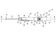
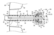
- the indwelling needle assembly 12 includes an indwelling needle 16 having a needle tip 14 and a needle tip protector 10 through which the indwelling needle 16 is movably inserted in the needle axis direction.
- the indwelling needle 16 is inserted into a patient's blood vessel.
- an external conduit 18 such as a cannula connected to the proximal end side of the indwelling needle assembly 12.
- the indwelling needle 16 After the indwelling needle 16 is used, the indwelling needle 16 is removed from the patient's blood vessel, and the needle tip protector 10 is moved toward the needle tip 14 so that the needle tip 14 of the indwelling needle 16 is moved by the needle tip protector 10. Covered and protected.
- the distal end side or the front side refers to the left side in FIG. 1 that is the needle tip 14 side of the indwelling needle 16, while the proximal end side or the rear side refers to the rear side in the puncture direction of the indwelling needle 16.
- the indwelling needle assembly 12 is configured by extrapolating and attaching the needle tip protector 10 to the needle unit 20 including the indwelling needle 16.
- the needle unit 20 includes an indwelling needle 16 and a needle hub 22 that fixes and supports the proximal end side of the indwelling needle 16.
- the indwelling needle 16 is a metal hollow needle, for example, and is formed of stainless steel or the like.
- the needle tip 14 of the indwelling needle 16 is tapered and has a sharp shape.
- a through-hole 24 is formed in the needle tip 14 of the indwelling needle 16 so that blood can easily flow into the indwelling needle 16.
- the needle hub 22 has a substantially cylindrical needle hub body 26 and a support portion 28 that fixes and supports the needle hub body 26 in the direction of the needle axis of the indwelling needle 16 (left-right direction in FIG. 1).
- the structure is connected to each other.
- the needle hub main body 26 has a cylindrical shape with a substantially constant inner diameter dimension as a whole, and is formed of, for example, a hard synthetic resin.
- the inner diameter of the needle hub main body 26 at the distal end opening is substantially equal to the outer diameter of the indwelling needle 16, while the inner peripheral surface of the needle hub main body 26 protrudes to the inner peripheral side.
- An annular positioning projection 30 is provided.
- the proximal end side of the indwelling needle 16 is inserted from the distal end side opening of the needle hub body 26, and the proximal end of the indwelling needle 16 and the positioning projection 30 are in contact with each other, whereby the proximal end of the indwelling needle 16 is positioned. It has come to be.
- the needle hub body 26 and the indwelling needle 16 are bonded, so that the indwelling needle 16 is fixedly supported at the tip of the needle hub body 26.
- the outer diameter of the needle hub body 26 is different in the needle axis direction. That is, a small-diameter cylindrical portion 32 having an outer diameter dimension smaller than that of the proximal end portion is provided at an axially intermediate portion of the needle hub body 26.
- the outer peripheral surface of the needle hub body 26 on the distal end side with respect to the small diameter cylindrical portion 32 is a tapered surface 34 whose outer diameter dimension gradually increases toward the distal end side.
- annular locking recess 36 that opens to the outer peripheral side is formed.
- the locking recess 36 has a predetermined width dimension (dimension in the needle axis direction), and the minimum outer diameter of the needle hub body 26 at the position where the locking recess 36 is formed is the outer diameter of the small diameter cylindrical portion 32. It is approximately equal to the dimensions.
- annular locking projection 38 protruding to the outer peripheral side is formed. The outer diameter of the locking projection 38 is larger than the maximum outer diameter of the tip of the tapered surface 34.
- the base end side surface constituting the inner surface of the locking recess 36 is an annular base end side regulating surface 40 as a third locking portion extending in a direction perpendicular to the axis with a predetermined dimension A (see FIG. 9).
- the bottom surface of the locking recess 36 and the tapered surface 34 are continued in a step shape by the base end side regulating surface 40.
- the side surface of the tip constituting the inner surface of the locking recess 36 is an annular tip-side regulating surface 42 as a fourth locking portion that spreads in the direction perpendicular to the axis with a predetermined dimension B (see FIG. 9).
- the bottom surface of the retaining recess 36 and the outer peripheral surface of the locking projection 38 are continuous in a stepped shape by the front end side regulation surface 42.
- the dimension A in the direction perpendicular to the axis of the base end side regulating surface 40 constituted by the base end side inner surface of the locking recess 36 is larger than the dimension B in the direction perpendicular to the axis of the distal end side regulating surface 42. It is slightly larger.
- the support portion 28 as a whole has a substantially cylindrical shape with a step formed on the inner peripheral surface, and is formed of, for example, a hard synthetic resin, like the needle hub body 26. That is, the distal end side is a connecting cylinder portion 44 having a small inner diameter dimension, and the proximal end side is a connecting cylinder portion 46 having a large inner diameter dimension. Then, the proximal end of the needle hub body 26 is inserted into the connecting tube portion 44 and bonded or welded as necessary, thereby connecting the needle hub body 26 and the support portion 28 to each other.
- a fluid flow path 48 extending from the blood vessel to the external conduit 18 is constituted by the inner holes of the indwelling needle 16 and the needle hub 22 (the needle hub body 26 and the support portion 28).
- a pair of engaging arms 50 and 50 projecting toward the distal end side with a predetermined width dimension are integrally formed on both sides in one radial direction (upper and lower sides in FIG. 1) at the outer peripheral edge of the connecting tube portion 46. Is formed.
- the engaging arms 50 and 50 have a substantially rectangular shape in plan view, and have a plate thickness dimension (vertical dimension in FIG. 1) and a width dimension (base dimension in FIG. 1) at the base end portion (connection portion with the connecting tube portion 46).
- the vertical dimension in FIG. 2 is thin, and slit-shaped gaps 52, 52 are formed between the connecting cylinder portion 44 and the engagement arms 50, 50 in the plate thickness direction. It can be elastically deformed. Further, hooks 56, 56 projecting to the outer peripheral side are formed at the tip portions of the engaging arms 50, 50.
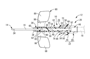
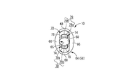
- the needle tip protector 10 has a substantially cylindrical shape extending in the needle axis direction as a whole, and is made of a hard material such as polypropylene, polycarbonate, glycol-modified polyethylene terephthalate, ABS resin, or the like. It is integrally formed of synthetic resin. That is, the needle tip protector 10 includes a cylindrical peripheral wall 58 and an inner hole 60 penetrating the inside of the peripheral wall 58 in the needle axis direction.
- the needle tip protector 10 (peripheral wall 58) has a different shape in the needle axis direction, the distal end side is a cylindrical portion 62 having a substantially circular ring cross section, and the proximal end side is a cylinder.
- the diameter-enlarged portion 64 is a larger-diameter portion than the shape-like portion 62 and spreads to the outer periphery. That is, the peripheral wall 58 of the needle tip protector 10 is configured to include the peripheral wall of the cylindrical portion 62 and the peripheral wall of the enlarged diameter portion 64, and the inner peripheral surface 65 of the peripheral wall 58 is the inner wall of the cylindrical portion 62.
- the peripheral surface and the inner peripheral surface of the peripheral wall of the enlarged diameter portion 64 are configured.
- the enlarged diameter portion 64 has a substantially elliptic cylindrical shape, and has a larger diameter in FIG. 6 than the width of the outer peripheral surface in the left-right direction, which is the small diameter direction in FIG. 6.
- the width dimension of the outer peripheral surface in the vertical direction, which is the direction, is made larger. That is, among the wall parts constituting the enlarged diameter part 64, the parts constituting the left and right wall parts in FIG. 6 are the small diameter parts 66, 66, while the vertical wall parts in FIG.
- the large diameter portions 68 and 68 are the portions where the small diameter portions 66 and 66 are opposed to each other, and the opposing directions of the small diameter portions 66 and 66 are orthogonal to each other.
- the outer diameter of the large diameter portions 68 and 68 is gradually increased from the distal end side to the proximal end side, and from the outer peripheral surface of the cylindrical portion 62 to the outer peripheral surface of the large diameter portions 68 and 68. Are connected by a smooth curved surface. Further, the thickness dimension from the cylindrical portion 62 to the large diameter portions 68, 68 is substantially constant in the needle axis direction, and is smaller than the thickness dimensions of the small diameter portions 66, 66. As a result, the inside of the enlarged diameter portion 64 has a cross-sectional shape that is substantially oval with the vertical dimension in FIG. 6 larger than the horizontal dimension in FIG. An inner space 70 in which the vertical dimension in FIG. 6 gradually increases is formed on the proximal end side of the inner hole 60 that penetrates the needle tip protector 10.
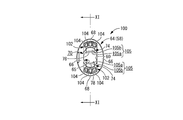
- the large-diameter portions 68 and 68 are formed with penetrating windows 72 and 72 as needle hub engaging portions penetrating in the plate thickness direction and extending with a predetermined circumferential dimension.
- the circumferential dimension of the through windows 72 and 72 is made larger than the circumferential dimension of the hooks 56 and 56.
- a pair of locking pieces 74, 74 as a pair of locking portions protruding inward are integrally formed from the inner peripheral surface 65 of the peripheral wall 58. These locking pieces 74, 74 are opposed to each other in positions corresponding to the large diameter portions 68, 68 in the large diameter portions 68, 68 in the enlarged diameter portion 64, that is, in the vertical direction in FIG. At a distance from each other).
- an annular stepped surface 76 having a predetermined dimension C (see FIG. 9) and extending in the direction perpendicular to the axis is formed on the inner peripheral surface 65 of the peripheral wall 58 at the front end portion of the enlarged diameter portion 64.
- the distal end side of the surface 76 has a larger diameter than the proximal end side.
- the stepped surface 76 is widened toward the outer periphery toward the front.
- the dimension C in the direction perpendicular to the axis of the stepped surface 76 is made smaller than the dimension B in the direction perpendicular to the axis of the front end side regulation surface 42 of the locking recess 36.
- locking pieces 74 are formed so as to protrude from the stepped surface 76 toward the proximal end side of the peripheral wall 58 on the proximal side of the stepped surface 76.
- the locking pieces 74, 74 extend from the stepped surface 76 toward the base end side substantially in parallel with the needle axis direction and are curved in the circumferential direction, respectively, and projecting tips (needle axis direction).
- Locking claws 78 and 78 that are bent toward the inner periphery are formed on the base end.
- the inner peripheral surfaces of these locking claws 78 and 78 are respectively curved in the circumferential direction, and the radius of curvature of the inner peripheral surfaces of the locking claws 78 and 78 is the outer diameter of the small diameter cylindrical portion 32 in the needle hub body 26. It is almost equal to the radius. Further, the distance between the opposing surfaces in the radial direction on the inner peripheral surfaces of the locking claws 78, 78 is substantially equal to the outer diameter of the small diameter cylindrical portion 32, while the maximum outer diameter of the tip portion of the tapered surface 34. It is smaller than the dimensions. However, the distance between the opposing surfaces in the radial direction on the inner peripheral surfaces of the locking claws 78, 78 may be slightly smaller than the outer diameter of the small-diameter cylindrical portion 32 or may be slightly larger. Good.
- the base end side end surfaces (protruding front end surfaces) 79 and 79 of the locking claws 78 and 78 are vertical surfaces 79a and 79a whose inner peripheral side extends in a direction perpendicular to the axis with a predetermined dimension D (see FIG. 9).
- the outer peripheral side is inclined surfaces 79b and 79b that incline toward the distal end as the outer peripheral side is reached.
- the dimension D in the direction perpendicular to the axis of the vertical surfaces 79a, 79a is substantially the same as or slightly larger than the dimension A in the direction perpendicular to the axis of the base end side regulating surface 40 of the locking recess 36.
- the locking claws 78, 78 abut on the proximal end regulating surface 40 and move toward the distal end side of the needle unit 20 (movement of the needle tip protector 10 toward the proximal end side in the needle axial direction). Is restricted, the entire base end side regulating surface 40 comes into contact with the vertical surfaces 79a and 79a, and a sufficiently large contact area can be secured. Furthermore, since the inclined surfaces 79b and 79b located on the outer peripheral side of the vertical surfaces 79a and 79a are inclined to the distal end side as they become the outer peripheral side, the vertical surfaces 79a and 79a and the base end side regulating surface 40 are formed. It can abut against the inclined surfaces 79b, 79b without interference, and the effect of preventing relative movement in the axial direction between the needle unit 20 and the needle tip protector 10 can be more reliably exhibited.
- the protruding tips (locking claws 78, 78) of the locking pieces 74, 74 are located on the tip side of the base end of the enlarged diameter portion 64. That is, the entire locking pieces 74 are provided in the accommodated state in the internal space 70 of the enlarged diameter portion 64.
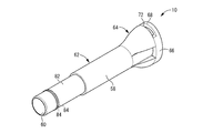
- a wing-like portion 80 is provided at the tip portion of the needle tip protector 10. That is, the distal end portion of the cylindrical portion 62 is a small-diameter cylindrical portion 82 having a smaller diameter than the other portions, and a plurality of protrusions projecting outward from the outer peripheral surface of the small-diameter cylindrical portion 82. Article 84 is formed. And the fitting cylinder part 90 provided with a pair of wing
- the indwelling needle assembly 12 is configured by inserting the needle unit 20 through the proximal end side opening in the inner hole 60 of the needle tip protector 10 having the above-described structure.
- the needle tip 14 of the indwelling needle 16 is located on the tip side of the needle tip protector 10, and the needle tip 14 is exposed. Yes.
- the hooks 56 and 56 of the engaging arms 50 and 50 provided on the needle hub 22 enter and are locked into the through windows 72 and 72 provided on the enlarged diameter portion 64 of the needle tip protector 10.
- the needle tip protector 10 and the needle hub 22 are connected, and the protruding state of the needle tip 14 is maintained.
- the locking claws 78 of the needle tip protector 10 are in contact with the outer peripheral surface of the small diameter cylindrical portion 32 of the needle hub body 26.
- the locking claws 78, 78 may be slightly pressed to the outer peripheral side by contacting the outer peripheral surface of the small diameter cylindrical portion 32, or slightly separated from the outer peripheral surface of the small diameter cylindrical portion 32. It may be.
- the indwelling needle assembly 12 having such a structure is used for infusion, blood collection, and hemodialysis through the fluid flow channel 48 by puncturing and placing the indwelling needle 16 in the blood vessel of the patient.
- the indwelling needle assembly 12 of the present embodiment since the wing-like portion 80 is provided, for example, the indwelling needle 16 can be punctured while grasping the wing-like portion 80. Further, when the indwelling needle 16 is indwelled in a puncture state, the indwelling needle 16 can be fixed with a wide contact area to the skin by fixing the tape at the position of the wing-shaped portion 80.
- the engagement arms 50 and 50 in the needle hub 22 are pressed inward with fingers while the needle tip protector 10 is tape-fixed in the wing-shaped portion 80. Accordingly, the hooks 56 and 56 and the through windows 72 and 72 are unlocked, and the needle unit 20 can be moved to the proximal end side with respect to the needle tip protector 10. Further, the needle unit protector 10 is moved toward the needle tip 14 of the needle unit 20 by moving the needle unit 20 toward the proximal end with respect to the needle tip protector 10 and removing the indwelling needle 16 from the skin.
- the locking claws 78 Since the outer peripheral surface on the distal end side of the small diameter cylindrical portion 32 with which 78 abuts is a tapered surface 34 whose outer diameter dimension gradually increases toward the distal end side, the needle unit 20 is attached to the needle tip protector 10. The needle unit 20 is prevented from moving unless an external force for moving it to the proximal side is applied. Thereby, the malfunction that the needle tip 14 of the indwelling needle 16 is protected by the needle tip protector 10 unintentionally can be prevented.
- the locking pieces 74, 74 are pressed toward the outer peripheral side by the tapered surface 34 of the needle hub body 26, and the locking claw 78. 78 are slid against the tapered surface 34.
- an elastic restoring force toward the inner peripheral side is exerted on the locking pieces 74 and 74 as an urging force. Therefore, the pressing force applied to the tapered surfaces 34 of the locking claws 78 and 78 becomes resistance, and the needle unit is confirmed while the user is pulling the needle unit 20 against the needle tip protector 10. 20 can be moved.
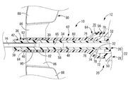
- the indwelling needle is moved by moving the needle unit 20 backward with respect to the needle tip protector 10 (moving the needle tip protector 10 forward toward the needle tip 14 of the needle unit 20).
- the 16 needle tips 14 are covered with the needle tip protector 10, and the locking claws 78, 78 of the locking pieces 74, 74 get over the tapered surface 34 of the needle hub body 26 and elastically return to the locking recess 36. It is supposed to go inside. In this state, the vertical surfaces 79a and 79a of the locking claws 78 and 78 are in contact with the proximal-side regulating surface 40 of the locking recess 36 (the locking claws 78 and 78 are locked to the proximal-side regulating surface 40).
- the stepped surface 76 provided at the front end portion of the locking pieces 74, 74 abuts on the tip side regulating surface 42 of the locking recess 36 (the stepped surface 76 is locked to the tip side regulating surface 42. Therefore, the movement of the needle unit 20 toward the proximal end side is restricted. This prevents the indwelling needle 16 from being pulled out to the proximal end side of the needle tip protector 10. Therefore, the movement of the needle unit 20 to both sides in the axial direction with respect to the needle tip protector 10 is prevented, and the protection state of the needle tip 14 of the indwelling needle 16 by the needle tip protector 10 is maintained.
- the locking claws 78, 78 provided on the free end side of the locking pieces 74, 74 are the first locking portions that prevent re-exposure of the needle tip 14 of the indwelling needle 16. Yes.
- the stepped surface 76 that integrally supports the fixed end sides of the locking pieces 74, 74 is a second locking portion that prevents the needle unit 20 from being pulled out from the proximal end side of the needle tip protector 10. ing.
- locking part (locking claw 78 and 78) have the vertical surfaces 79a and 79a as a 1st axis
- the locking part (stepped surface 76) is a second axis facing the axis extending in the direction perpendicular to the axis.
- the base end side surface (base end side regulating surface 40) is the third locking portion and faces the third axis extending in the direction perpendicular to the axis
- the tip side surface (tip end)
- the needle tip protector 10 since a pair of locking portions (locking pieces 74, 74) are provided, it is also compatible with the locking portion being integrally formed on the peripheral wall 58 of the needle tip protector 10.
- the needle tip protector 10 is more reliably prevented from retracting toward the proximal end side of the indwelling needle 16, and the needle tip The re-exposure preventing effect can be exhibited more stably.
- the plurality of locking portions are preferably provided substantially symmetrically with respect to the central axis of the needle tip protector 10.
- the tape fixing in the wing 80 is released, and the indwelling needle assembly 12 is removed from the patient. According to this removal procedure, since the needle tip 14 is not exposed at all from the puncture to the disposal of the indwelling needle 16, erroneous puncture or the like can be prevented more reliably.
- the procedure for protecting the needle tip 14 is not limited to the above procedure. After the tape fixing in the wing-shaped portion 80 is released and the indwelling needle 16 is removed from the blood vessel, the needle unit 20 is attached to the needle tip protector 10. The needle tip 14 of the indwelling needle 16 may be protected by moving backward.
- the tips of the locking claws 78, 78 come into contact with the bottom surface of the locking recess 36, so that the impact and sound of the contact are received by the user.
- the possibility of interrupting the pulling-out operation of the needle unit 20 in the middle is avoided. Thereby, protection of the needle tip 14 of the indwelling needle 16 by the needle tip protector 10 can be realized more reliably.
- the locking pieces 74 and 74 for preventing the re-exposure of the needle tip 14 of the indwelling needle 16 are provided inside the cylindrical peripheral wall 58, in particular. Since the entirety is accommodated and provided, it is substantially impossible to contact the locking pieces 74 and 74 from outside without intention. Therefore, in the state in which the needle tip 14 of the indwelling needle 16 is protected by the needle tip protector 10, the locking of the locking pieces 74, 74 and the locking recess 36 is unintentionally released and the needle tip 14 of the indwelling needle 16 is moved. Re-exposure from the needle tip protector 10 can be effectively prevented.
- the locking pieces 74 and 74 are provided on the enlarged diameter portion 64 which is expanded on the proximal end side of the needle tip protector 10. Accordingly, the needle hub 22 (needle hub body 26) inserted between the locking pieces 74 and 74 has a sufficiently large outer diameter while ensuring a sufficient size of the locking pieces 74 and 74. Can be done. Furthermore, in the present embodiment, the enlarged diameter portion 64 is substantially elliptical, and the outer peripheral surface thereof is smoothly continuous from the outer peripheral surface of the cylindrical portion 62. There is a reduced risk that the patient will feel pain in contact.
- the locking pieces 74 and 74 are provided inside the large diameter portions 68 and 68 constituting the substantially elliptical enlarged diameter portion 64, the space inside the large diameter portions 68 and 68 is skillfully formed.
- the large-diameter portions 68 and 68 can be prevented from becoming thick, and the occurrence of dimensional errors and deterioration of quality accuracy due to the mixing of bubbles into the member during molding can be suppressed.
- locking part (locking piece 74,74) is provided so that it may extend in the same direction (base end side of an axial direction) as the large diameter parts 68 and 68.
- the space inside the large diameter portions 68, 68 can be used skillfully, and the large diameter portions 68, 68 can be used. Is prevented from becoming thick, and it is possible to suppress the occurrence of dimensional errors and the deterioration of quality accuracy due to air bubbles mixed into the member during molding.
- the locking pieces 74 are provided so as to protrude into the peripheral wall 58, for example, when the needle tip protector 10 is manufactured by molding, the mold is removed in the needle axis direction of the needle tip protector 10. It is possible to mold, and the number of types of molds can be reduced. Therefore, the manufacturing efficiency of the needle tip protector 10 can be improved.
- the locking pieces 74 and 74 extend toward the proximal end side, they are not caught when the needle unit 20 is pulled out from the needle tip protector 10, and smooth pulling out can be realized.
- the protection state of the needle tip 14 of the indwelling needle 16 by the needle tip protector 10 that is, the locking pieces 74 and 74 are locked.
- the needle hub body 26 can be held between the radial directions by the locking pieces 74, 74. Therefore, the needle tip protector 10 and the needle unit 20 (needle hub body 26) do not wobble between the radial directions, and the protection state of the needle tip 14 of the indwelling needle 16 by the needle tip protector 10 is stably maintained. Can be done.
- the locking claws 78, 78 that are the first locking portions and the proximal end regulation surface 40 of the locking recess 36 that is the third locking portion abut each other.
- the needle tip protector 10 can be prevented from moving to the proximal end side with respect to the needle unit 20.
- the stepped surface 76 that is the second locking portion and the distal-end-side regulating surface 42 of the locking recess 36 that is the fourth locking portion abut each other, so that the needle tip protector 10 is against the needle unit 20. Can be prevented from moving to the tip side.
- each of the first to fourth locking portions has first to fourth shaft faces extending in a direction perpendicular to the axis, and therefore, there is no undercut shape and molding is easy.
- the contact reaction force can be efficiently generated as an axial force.
- each contact area can also be ensured sufficiently and the movement of the needle tip protector 10 toward the distal end side and the proximal end side with respect to the needle unit 20 can be more reliably prevented.
- FIGS. 10 and 11 show a needle tip protector 100 for an indwelling needle as a second embodiment of the present invention.
- the structure of the needle tip protector 100 of the present embodiment is substantially the same as that of the first embodiment.
- a deformation amount limiting portion 102 is provided for limiting the deformation amount of the locking pieces 74, 74 to the outer peripheral side.
- members and portions that are substantially the same as those in the first embodiment are denoted by the same reference numerals as those in the first embodiment in the drawing, and detailed description thereof is omitted. .
- deformation amount limiting portions 102 and 102 are provided between the peripheral wall 58 and the locking pieces 74 and 74 in the radial direction in the internal space 70 of the enlarged diameter portion 64.
- the deformation amount limiting portions 102, 102 projecting toward the proximal end are integrally formed on the inner peripheral surface 65 of the large diameter portion 68, 68 constituting the enlarged diameter portion 64. Is formed.
- the wall portions constituting the large-diameter portions 68 and 68 in the enlarged-diameter portion 64 are partially thickened, whereby the deformation amount limiting portions 102 and 102 are formed.
- the deformation amount limiting portions 102 and 102 gradually increase in the radial dimension (in FIG. 11) toward the proximal end side.
- the vertical dimension of the vertical cross section shown in FIG. 11 is substantially a right triangle.
- the inner peripheral surfaces of the deformation amount limiting portions 102, 102 extend substantially parallel to the locking pieces 74, 74 (that is, substantially parallel to the needle axis direction of the indwelling needle 16), while the proximal end surface is the indwelling needle. It spreads in a direction substantially orthogonal to the 16 needle axis directions.
- the base end surfaces of the deformation amount limiting portions 102 and 102 are located on the tip side in the needle axis direction with respect to the needle shaft direction base ends (protruding leading ends) of the locking pieces 74 and 74, and the deformation amount limiting portions 102 and 102 are located. Is housed in the internal space 70 of the enlarged diameter portion 64.
- each deformation amount limiting portion 102, 102 is composed of three protrusions 104, 104, 104 protruding from the inner peripheral surface 65 of the enlarged diameter portion 64 toward the proximal end side.
- These three protrusions 104, 104, 104 are circumferentially arranged between the wall portions (between the left and right directions in FIG. 10) constituting the small diameter portions 66, 66 which are thicker than the large diameter portions 68, 68.
- these three protrusions 104, 104, 104 are also in the radial direction (vertical direction in FIG. 10) of the locking piece 74, and protect the needle tip from the state before the needle tip protection (for example, see FIGS. 3 and 4). They are provided at an appropriate distance so as not to hinder the movement of the needle tip protector 100 to a state (for example, see FIGS. 7 and 8).
- the inner peripheral surface of the deformation amount limiting portion 102 including these three protrusions 104, 104, 104 has a curved shape substantially corresponding to the outer peripheral surface of the locking piece 74.
- the portions 104, 104, 104 and the locking piece 74 are separated by a substantially constant distance.
- the separation distance between the protrusions 104, 104, 104 and the locking piece 74 hinders deformation of the locking piece 74 toward the outer peripheral side when the needle unit 20 moves toward the distal end side with respect to the needle unit 20.
- the amount of deformation of the locking piece 74 abuts against the deformation amount limiting portion 102 (protrusions 104, 104, 104) when the indwelling needle assembly 106 is bent and deformed, as will be described later. Is set to a size regulated by
- the dimension E (see FIG. 13) in the direction perpendicular to the axis of the vertical surfaces 105a and 105a as the first axis faces on the base end side end surfaces 105 and 105 of the locking pieces 74 and 74 is It is smaller than the dimension A in the direction perpendicular to the axis at the base end side regulating surface 40 (facing the third axis) of the recess 36.
- the outer peripheral end ⁇ of the vertical surface 105a of the locking piece 74 is positioned on the inner peripheral side of the outer peripheral end ⁇ of the proximal-side regulating surface 40 of the locking recess 36, and this is applied.
- the indwelling needle tip protector 100 having such a structure is extrapolated to the needle unit 20 having the same structure as that of the first embodiment, so that the indwelling needle assembly 106 (FIG. 12). Then, as in the first embodiment, the indwelling needle assembly 106 is punctured, and after the puncture, the needle tip protector 100 is moved to the needle tip 14 side of the indwelling needle 16 as shown in FIGS. By moving the needle tip protector 100, the needle tip 14 of the indwelling needle 16 is protected. That is, the locking claws 78, 78 provided at the distal ends of the locking pieces 74, 74 enter the locking recess 36 provided at the distal end portion of the needle hub body 26 and are locked.
- the deformation amount limiting portions 102, 102 are provided on the outer peripheral side of the locking pieces 74, 74, the locking claw 78 of the locking claw 78 is protected in the protected state of the needle tip 14 of the indwelling needle 16. Unintentional detachment from the locking recess 36 can be effectively prevented. Specifically, for example, under the protection state of the needle tip 14, an external force in the bending direction is applied to the entire needle tip protector 100 and the needle unit 20, and one locking piece 74 is pushed by the needle hub body 26. When greatly deformed outward, the locking claw 78 of the other locking piece 74 floats outward from the base end side regulation surface 40, and the locked state is released or the locking piece 74 is damaged.
- indwelling needle tip protector 100 and indwelling needle assembly 106 of the present embodiment the same effects as in the first embodiment can be exhibited.
- the deformation amount limiting portions 102 and 102 are provided on the inner peripheral side of the large diameter portions 68 and 68 in the large diameter portion 64, and the internal space 70 of the large diameter portion 64 can be used skillfully.
- an increase in the size of the needle tip protector 100 accompanying the provision of a deformation amount limiting mechanism for the locking pieces 74, 74 can be avoided.
- the dimension E in the direction perpendicular to the axis of the vertical surfaces 105 a and 105 a is the axis on the base end side regulating surface 40 of the locking recess 36.
- the outer end ⁇ of the vertical surface 105 a of the locking piece 74 is brought into contact with the base-side regulating surface 40 by being smaller than the dimension A in the perpendicular direction.
- the vertical surface 105a that contacts the base end side regulating surface 40 in the locking claw 78 is biased toward the inner peripheral side from the central axis of the locking piece 74, so that the bending moment due to the contact reaction force acts.
- the locking piece 74 may be deformed into a curved shape that protrudes outward, and the vertical surface 105a of the locking claw 78 may be inclined. In the inclined state of the vertical surface 105a, when the end portion ⁇ of the vertical surface 105a is positioned on the outer peripheral side from the end portion ⁇ of the base end side regulating surface 40, the end portion ⁇ of the base end side regulating surface 40 is inclined.
- the locking pieces 74 and 74 extend toward the proximal end side, but may extend toward the distal end side.
- the entire locking pieces 74, 74 are accommodated inside the peripheral wall 58.
- the front end of the locking portion is located outward from the end in the needle axis direction of the peripheral wall. It may be.
- the substantial latching part (for example, latching claw 78, 78 in the said embodiment) in a latching part does not need to be provided in the front-end
- the inner peripheral side is the vertical surfaces 79a and 79a (105a and 105), while the outer peripheral side is inclined.
- the surface 79b, 79b (105b, 105b) it is not limited to this aspect. That is, the base end side end surfaces 79 and 79 (105 and 105) of the locking pieces 74 and 74 are spread in the direction perpendicular to the axis over substantially the entire surface without the inclined surfaces 79b and 79b (105b and 105b).
- the vertical surfaces 79a and 79a may be provided in a direction inclined with respect to the axial direction over substantially the entire surface.
- the inclined surfaces 79b and 79b may be inclined toward the distal end side toward the outer peripheral side as in the above embodiment, or the vertical surfaces 79a and 79a (105a and 105a) and the proximal end side. As long as it does not interfere with the contact with the restricting surface 40, it may be inclined toward the base end as it becomes the outer peripheral side.
- the inner peripheral side portion of the base end side end surfaces 79, 79 (105, 105) of the locking pieces 74, 74 and the base end side regulating surface 40 of the needle hub main body 26 are replaced with a vertical surface as shown in the example. It is also possible to make the inclined surface inclined toward the distal end side as it goes to the side, whereby the proximal side regulating surface 40 becomes an undercut having an overhang shape, but it is also possible to obtain a larger movement regulating force become.
- the pair of locking pieces 74 and 74 are provided to face each other in the radial direction.
- the number of the locking portions may be one, or may be three or more. In this case, it is preferable that three or more locking portions are provided at substantially equal intervals in the circumferential direction. Or you may be set as the substantially cylindrical latching
- the latching recessed part provided in a needle hub main body does not need to be provided continuously over the perimeter, and should just be provided in the position corresponding to a latching part in the circumferential direction.
- the stepped surface 76 provided on the fixed end side of the locking pieces 74, 74 in the needle tip protector 10, 100, and the tip side regulating surface provided on the needle hub 22 (needle hub body 26). 42 is prevented from being pulled out from the proximal end side of the needle unit 20 from the needle tip protectors 10, 100, but the mechanism for preventing the needle unit from being pulled out is limited to such a mode. is not. That is, the stepped surface 76 and the front end side regulating surface 42 are not essential, and a needle unit extraction preventing mechanism may be provided separately from these.
- the stepped surface 76, the base end side regulating surface 40, the distal end side regulating surface 42, etc. spread in the direction perpendicular to the axis, but these may be inclined and spread with respect to the direction perpendicular to the axis. Good.
- the base end side of the needle point protectors 10 and 100 was made into the cylindrical part 62 which has an annular cross section
- the base end side was made into the enlarged diameter part 64 of elliptical cylinder shape, but these shapes It is not limited to. That is, various shapes such as a circular shape (including an ellipse, an ellipse, a semicircle, and the like) and a polygonal shape can be adopted as the cross-sectional shapes at the distal end side and proximal end side expanded portions of the needle tip protector.
- the widened portion provided on the proximal end side of the needle tip protector is not essential, and the needle tip protector may be a simple straight tube shape.
- the shape of the needle unit is not limited.
- the needle hub 22 and the needle tip protectors 10 and 100 are connected, that is, the hooks 56 and 56 are locked to the through windows 72 and 72 to maintain the indwelling needle 16 in an exposed state.
- the present invention is not limited to such an embodiment. That is, the needle hub engaging portion does not need to have a through window shape as in the above-described embodiment, and may have a bottomed groove shape that opens to the inner peripheral side.
- a hook as a needle hub engaging portion may be formed on the needle tip protector, and a penetrating window or a bottomed groove may be formed on the needle hub.
- these hooks and through windows are not essential, and in short, a connection mechanism between the needle hub and the needle tip protector before use is not essential.
- the wing-shaped portion 80 is attached to the needle tip protectors 10, 100, but the wing-shaped portion is not essential.
- the deformation amount limiting portions 102 and 102 are integrally formed with the enlarged-diameter portion 64 of the needle tip protector 100, but may be formed separately and later fixed. Thereby, for example, the deformation amount limiting portion can be formed of a material different from that of the needle tip protector.
- the deformation amount limiting portions 102, 102 are provided on the inner peripheral surface 65 of the wall portion constituting the large diameter portions 68, 68 in the enlarged diameter portion 64.
- the formation position of the limiting portion is not limited at all. That is, the deformation amount limiting portion is provided so as to protrude from the inner peripheral surface of the wall portion constituting the small diameter portion in the enlarged diameter portion toward the outer peripheral side of the locking portions (locking pieces 74, 74), for example. May be.
- the deformation amount limiting portion is not limited to the aspect provided on the inner peripheral surface of the enlarged diameter portion.
- the deformation amount limiting portion is provided on the outer peripheral surface of the locking portion and is elastically deformed toward the outer peripheral side of the locking portion. The deformation may be limited by contacting the inner peripheral surface of the enlarged diameter portion.
- the shape of the deformation amount limiting portion is not limited at all.
- the deformation amount limiting portions 102, 102 have a substantially right-angled triangular longitudinal section, but, for example, a protrusion protruding from the inner peripheral surface of the enlarged diameter portion to the proximal end side or the inner peripheral side. It may be in the form of a piece, or may be in the form of a protruding piece that protrudes from the outer peripheral surface of the locking portion (locking pieces 74, 74) to the outer peripheral side.
- the deformation amount limiting portions 102, 102 are each composed of the three protrusions 104, 104, 104, but the present invention is not limited to this mode, and one or two of them are not limited. You may be comprised from four or more protrusions.
- the deformation amount limiting portions 102 and 102 by configuring the deformation amount limiting portions 102 and 102 with a plurality of protrusions in this way, it is possible to reduce the sink time (deformation due to thermal shrinkage) after molding and shorten the molding time associated with improving cooling efficiency. .
- the two locking pieces 74, 74 are provided, and the deformation amount limiting portions 102, 102 are provided on the outer peripheral side of the respective locking pieces 74, 74.
- the deformation amount limiting portion may be provided only on the outer peripheral side of any one of the locking portions (locking pieces 74).
- Needle tip protector for indwelling needle 12, 106: Indwelling needle assembly, 14: Needle tip, 16: Indwelling needle, 22: Needle hub, 40: Proximal-side regulating surface (third locking portion, Triaxial face), 42: Tip side regulating surface (fourth locking part, fourth axis face), 58: peripheral wall, 64: diameter-expanded part (expanded part), 66: small-diameter part, 68: large-diameter part, 72: penetrating window (needle hub engaging portion), 74: locking piece (locking portion), 76: stepped surface (second locking portion, facing the second shaft), 78: locking claw (first locking) 79), 105: base end side end surface, 79a, 105a: vertical surface (facing the first axis), 102: deformation amount limiting portion
Abstract
The present invention provides a needlepoint protector of a novel structure for an indwelling needle, which enables improvements in safety, etc. as compared with conventional needlepoint protectors. The needlepoint protector 10 for an indwelling needle according to the present invention is provided with a tubular peripheral wall 58, and is externally attached over a needle hub 22 of an indwelling needle 16 and moved toward a needlepoint 14 side so as to cover the needlepoint 14 of the indwelling needle 16. Engagement parts 74, 74, which are to be engaged with the needle hub 22 at a position reached when being moved toward the needlepoint 14 side of the indwelling needle 16 so as to inhibit the indwelling needle 16 from retreating toward the base end side and to prevent the needlepoint 14 from being re-exposed, are formed within the interior space enclosed by the tubular peripheral wall 58, and are integrally molded with the tubular peripheral wall 58.
Description
本発明は、血管に穿刺されて留置される留置針の使用後に当該留置針の針先を保護する留置針用針先プロテクタ、および針先プロテクタを備える留置針組立体に関するものである。
The present invention relates to an indwelling needle tip protector that protects the needle tip of an indwelling needle after use of an indwelling needle that is punctured into a blood vessel, and an indwelling needle assembly including the needle tip protector.
従来から、輸液や採血、血液透析を行う際に用いられる留置針が知られている。この留置針は、先端に針先を備えている一方、基端は針ハブに固定されている。かかる留置針が患者の血管に穿刺されて留置されることで、針ハブに接続されるカヌラなどの外部管路を通じて、輸液や採血、血液透析が実施されるようになっている。
Conventionally, indwelling needles used for infusion, blood collection, and hemodialysis are known. The indwelling needle has a needle tip at the distal end, while the proximal end is fixed to the needle hub. When such an indwelling needle is punctured and placed in a patient's blood vessel, infusion, blood collection, and hemodialysis are performed through an external conduit such as a cannula connected to a needle hub.
ところで、留置針は、誤穿刺や再使用の防止、或いは廃棄処理の容易化などの目的で、使用後の針先を保護する針先プロテクタを備えているものがある。たとえば、かかる留置針用の針先プロテクタおよび針先プロテクタを備えた留置針組立体としては、本出願人が提案した特許第3134920号公報(特許文献1)などがある。
By the way, some indwelling needles are provided with a needle tip protector for protecting the needle tip after use in order to prevent erroneous puncture and reuse, or to facilitate disposal. For example, Japanese Patent No. 3134920 (Patent Document 1) proposed by the present applicant is an example of a needle tip protector for an indwelling needle and an indwelling needle assembly including the needle tip protector.
すなわち、特許文献1に記載の針先プロテクタは筒状の周壁を備えており、留置針の使用後に当該周壁を針先側に移動させることで、留置針の針先が針先プロテクタにより保護されるようになっている。具体的には、留置針の使用前には、針先プロテクタと針ハブとが、留置針の針先が露出する状態で連結固定されているが、使用後に針先プロテクタと針ハブとの連結を解除することで、針先プロテクタが針ハブに対して針先側へ移動して針先を保護するとともに、係止部(可撓性衝合枝43)でかかる状態を保持することができるようになっている。このような針先プロテクタおよび留置針組立体を採用すれば、留置針の針先が安全に保護できて、誤穿刺などのおそれが効果的に防止され得る。
That is, the needle tip protector described in Patent Document 1 includes a cylindrical peripheral wall, and the needle tip of the indwelling needle is protected by the needle tip protector by moving the peripheral wall to the needle tip side after use of the indwelling needle. It has become so. Specifically, before using the indwelling needle, the needle tip protector and the needle hub are connected and fixed in a state where the needle tip of the indwelling needle is exposed, but after use, the needle tip protector and the needle hub are connected. , The needle tip protector moves toward the needle tip side with respect to the needle hub to protect the needle tip, and this state can be maintained by the locking portion (flexible abutting branch 43). It is like that. If such a needle tip protector and an indwelling needle assembly are employed, the needle tip of the indwelling needle can be safely protected, and the possibility of erroneous puncture can be effectively prevented.
そして、本出願人は、かかる針先プロテクタおよび留置針組立体の更なる改良を検討して、上記特許文献1に記載の針先プロテクタおよび留置針組立体よりも、安全性などに優れた本発明を開発し得たのである。
Then, the present applicant has studied further improvements of the needle tip protector and the indwelling needle assembly, and is a book superior in safety than the needle tip protector and indwelling needle assembly described in Patent Document 1. The invention could be developed.
本発明は、上述の事情を背景に為されたものであって、その解決課題は、従来よりも安全性などの向上を図ることのできる、新規な構造の留置針用針先プロテクタおよび留置針組立体を提供することにある。
The present invention has been made in the background of the above-mentioned circumstances, and the problem to be solved is a needle tip protector for an indwelling needle and an indwelling needle having a novel structure capable of improving safety and the like as compared with the prior art. It is to provide an assembly.
以下、このような課題を解決するために為された本発明の態様を記載する。なお、以下に記載の各態様において採用される構成要素は、可能な限り任意の組み合わせで採用可能である。
Hereinafter, embodiments of the present invention made to solve such problems will be described. In addition, the component employ | adopted in each aspect as described below is employable by arbitrary combinations as much as possible.
本発明の第1の態様は、筒状の周壁を備えており、留置針の針ハブに外挿装着されて針先側へ移動することで該留置針の針先を覆う針先プロテクタであって、前記留置針の針先側への移動位置において前記針ハブに係止されて、該留置針の基端側への後退を阻止することで前記針先の再露出を防止する係止部が、前記筒状の周壁で覆われた内部に形成されていると共に、該係止部が該筒状の周壁に一体成形されていることを特徴とするものである。
A first aspect of the present invention is a needle tip protector that includes a cylindrical peripheral wall, and is attached to a needle hub of an indwelling needle so as to cover the needle tip of the indwelling needle by moving toward the needle tip side. A locking portion that is locked to the needle hub at a position where the indwelling needle moves toward the needle tip side and prevents re-exposure of the needle tip by preventing the indwelling needle from moving backward to the proximal end side. Is formed inside the cylindrical peripheral wall, and the locking portion is integrally formed with the cylindrical peripheral wall.
本態様に従う構造とされた留置針用針先プロテクタによれば、針先の再露出を防止する係止部が周壁の内部に一体的に形成されていることから、係止部に対して外部からアクセスし難くできる。その結果、意図せず係止部に接触したり何らかの外力により係止部が破損して、針先の保護状態が解除されるようなことも防止することが可能になる。
According to the indwelling needle tip protector structured according to this aspect, the locking portion that prevents re-exposure of the needle tip is integrally formed inside the peripheral wall. It is difficult to access from. As a result, it is possible to prevent the protection state of the needle tip from being released due to unintentional contact with the locking portion or damage to the locking portion due to some external force.
本発明の第2の態様は、前記第1の態様に係る留置針用針先プロテクタにおいて、前記係止部が、前記筒状の周壁内で該周壁の基端側に向かって延びているものである。
According to a second aspect of the present invention, in the indwelling needle tip protector according to the first aspect, the locking portion extends toward the proximal end side of the peripheral wall in the cylindrical peripheral wall. It is.
本態様に従う構造とされた留置針用針先プロテクタによれば、係止部が周壁の基端側に向かって延びていることから、針先プロテクタに対して留置針を基端側へ移動させる際に、例えば係止部が先端側へ延びている場合に比べて、引っ掛かったり、使用者が抵抗感を感じるおそれが低減され得る。
According to the indwelling needle tip protector having the structure according to this aspect, since the locking portion extends toward the proximal end side of the peripheral wall, the indwelling needle is moved toward the proximal end side with respect to the needle tip protector. In this case, for example, the possibility of being caught or feeling the resistance of the user can be reduced as compared with the case where the locking portion extends to the tip side.
本発明の第3の態様は、前記第1又は第2の態様に係る留置針用針先プロテクタにおいて、前記係止部の全体が、前記筒状の周壁で覆われた内部に収容状態とされているものである。
According to a third aspect of the present invention, in the needle tip protector for an indwelling needle according to the first or second aspect, the entire locking portion is housed in an interior covered with the cylindrical peripheral wall. It is what.
本態様に従う構造とされた留置針用針先プロテクタによれば、係止部の全体が周壁の内部に収容されていることから、係止部への外部からのアクセスが一層困難とされており、針先が意図せず露出することが更に効果的に防止されて、安全性の更なる向上が図られ得る。
According to the indwelling needle tip protector structured according to this aspect, since the entire locking portion is housed inside the peripheral wall, it is further difficult to access the locking portion from the outside. Further, it is possible to further effectively prevent the needle tip from being unintentionally exposed and further improve safety.
本発明の第4の態様は、前記第1~第3の何れかの態様に係る留置針用針先プロテクタにおいて、前記筒状の周壁の基端側に外周に広がる拡開部が設けられており、該拡開部の中に前記係止部が設けられているものである。
According to a fourth aspect of the present invention, in the indwelling needle tip protector according to any one of the first to third aspects, an expanding portion that extends to the outer periphery is provided on the proximal end side of the cylindrical peripheral wall. The locking portion is provided in the expanding portion.
本態様に従う構造とされた留置針用針先プロテクタによれば、周壁の基端側に設けられた拡開部の中に係止部が設けられていることから、係止部の大きさを十分に確保しつつ、周壁に挿通される針ハブの径が小さくなり過ぎることも回避される。
According to the indwelling needle tip protector configured according to this aspect, since the locking portion is provided in the widened portion provided on the proximal end side of the peripheral wall, the size of the locking portion is reduced. While ensuring sufficiently, it is also avoided that the diameter of the needle hub inserted through the peripheral wall becomes too small.
本発明の第5の態様は、前記第4の態様に係る留置針用針先プロテクタにおいて、前記拡開部の前端部分には、前記筒状の周壁の内周面において前方に向かって外周側に広がる段差状面が設けられており、該段差状面よりも該拡開部の後端部分において後方に向かって前記係止部が突出形成されているものである。
According to a fifth aspect of the present invention, in the needle tip protector for an indwelling needle according to the fourth aspect, the front end portion of the expanding portion has an outer peripheral side toward the front on the inner peripheral surface of the cylindrical peripheral wall. A stepped surface extending in the direction is provided, and the locking portion protrudes rearward from the stepped surface at the rear end portion of the expanded portion.
本態様に従う構造とされた留置針用針先プロテクタによれば、周壁の内周面に、前方に向かって外周側に広がる段差状面が設けられていることから、例えば針ハブの外周面に外周側に突出する係止凸部を設けることで、針先プロテクタに対して留置針を基端側へ移動させた際に、係止凸部と段差状面とが係合して、それ以上の留置針の基端側への移動が制限され得る。それ故、係止部を利用して、留置針が針先プロテクタの基端側から抜け落ちることを防止することも可能となる。
According to the indwelling needle tip protector having the structure according to this aspect, since the stepped surface extending toward the outer peripheral side toward the front is provided on the inner peripheral surface of the peripheral wall, for example, on the outer peripheral surface of the needle hub. By providing a locking projection that protrudes to the outer peripheral side, when the indwelling needle is moved to the proximal end side with respect to the needle tip protector, the locking projection and the stepped surface engage with each other. The movement of the indwelling needle to the proximal side can be restricted. Therefore, it is possible to prevent the indwelling needle from falling off from the proximal end side of the needle tip protector using the locking portion.
本発明の第6の態様は、前記第4又は第5の態様に係る留置針用針先プロテクタにおいて、前記拡開部が、互いに直交する小径部と大径部とを備えた略楕円筒形状とされており、該大径部の周壁で覆われた内部に前記係止部が設けられていると共に、該大径部の周壁において前記針ハブが係合されて前記留置針の針先が突出状態に保持される針ハブ係合部が設けられているものである。
According to a sixth aspect of the present invention, in the needle tip protector for an indwelling needle according to the fourth or fifth aspect, the widened portion has a substantially elliptic cylindrical shape having a small diameter portion and a large diameter portion that are orthogonal to each other. The locking portion is provided in the inside covered with the peripheral wall of the large diameter portion, and the needle hub is engaged with the peripheral wall of the large diameter portion so that the needle tip of the indwelling needle is A needle hub engaging portion that is held in a protruding state is provided.
本態様に従う構造とされた留置針用針先プロテクタによれば、拡開部が角部を備えていない略楕円筒形状とされていることから、拡開部が患者に接触して患者が痛みを感じるおそれが低減され得る。特に、拡開部が小径部を備えていることから、患者への接触量を小さくすることができて、患者が痛みを感じるおそれが一層低減され得る。
According to the indwelling needle tip protector structured according to this aspect, since the expanded portion has a substantially elliptical cylindrical shape without corners, the expanded portion comes into contact with the patient and the patient is in pain. The risk of feeling can be reduced. In particular, since the widened portion includes the small diameter portion, the contact amount to the patient can be reduced, and the risk that the patient feels pain can be further reduced.
また、単に肉厚の大径部を設けるのではなく、大径部の内部に係止部を設けることで、拡開部の内部スペースを巧く利用することができるとともに、部材内へのエアの混入を効果的に防止することができて、寸法誤差を小さくできるなど製品の品質も向上され得る。
In addition, it is possible not only to provide a large-diameter portion with a thick wall, but also to provide a locking portion inside the large-diameter portion, so that the internal space of the expanded portion can be used skillfully and air into the member can be used. As a result, the quality of the product can be improved. For example, the dimensional error can be reduced.
本発明の第7の態様は、前記第1~第6の何れかの態様に係る留置針用針先プロテクタにおいて、前記筒状の周壁の周方向において互いに離隔して複数の前記係止部が設けられているものである。
A seventh aspect of the present invention is the indwelling needle tip protector according to any one of the first to sixth aspects, wherein a plurality of the locking portions are separated from each other in the circumferential direction of the cylindrical peripheral wall. It is provided.
本態様に従う構造とされた留置針用針先プロテクタによれば、周方向において互いに離隔して複数の係止部が設けられていることから、留置針の基端側への後退がより確実に阻止されて、針先の再露出防止効果が一層安定して発揮され得る。
According to the indwelling needle tip protector having the structure according to this aspect, since the plurality of locking portions are provided apart from each other in the circumferential direction, the indwelling needle is more reliably retracted to the proximal end side. This prevents the needle tip from re-exposure and can be more stably exhibited.
本発明の第8の態様は、前記第1~第7の何れかの態様に係る留置針用針先プロテクタにおいて、前記係止部において前記筒状の周壁から延びる自由端側が、前記針ハブへの係止により該筒状の周壁内での前記留置針の針先側への移動による針先再露出を阻止する第一係止部とされていると共に、該係止部において該筒状の周壁によって一体的に支持された固定端側が、該針ハブへの係止により該筒状の周壁内での該留置針の基端側への移動による針抜出しを阻止する第二係止部とされているものである。
An eighth aspect of the present invention is the indwelling needle tip protector according to any one of the first to seventh aspects, wherein a free end side extending from the cylindrical peripheral wall at the locking portion is connected to the needle hub. The first locking portion that prevents re-exposure of the needle tip due to the movement of the indwelling needle toward the needle tip side within the cylindrical peripheral wall is provided at the locking portion. A fixed end side integrally supported by the peripheral wall; and a second locking portion for preventing needle withdrawal due to movement of the indwelling needle to the proximal end side in the cylindrical peripheral wall by locking to the needle hub. It is what has been.
本態様に従う構造とされた留置針用針先プロテクタによれば、周壁に形成された係止部により留置針の針先プロテクタに対する先端側および基端側への両方向の移動が防止されることから、針先再露出阻止機構と針抜出阻止機構を別々に設ける場合に比べて、構造を簡単なものとすることができる。
According to the indwelling needle tip protector having the structure according to this aspect, the locking portion formed on the peripheral wall prevents the indwelling needle from moving in both directions toward the distal end side and the proximal end side with respect to the needle tip protector. As compared with the case where the needle tip re-exposure prevention mechanism and the needle extraction prevention mechanism are provided separately, the structure can be simplified.
本発明の第9の態様は、前記第1~第8の何れかの態様に係る留置針用針先プロテクタにおいて、前記係止部の外周側への変形量を制限する変形量制限部が設けられているものである。
According to a ninth aspect of the present invention, in the indwelling needle tip protector according to any one of the first to eighth aspects, a deformation amount limiting portion is provided that limits a deformation amount of the locking portion toward the outer peripheral side. It is what has been.
本態様に従う構造とされた留置針用針先プロテクタによれば、留置針の針先側に移動して係止部が針ハブに係止された状態において、留置針用針先プロテクタおよび/または針ハブに、例えば曲げ方向などの外力が及ぼされた場合にも、変形量制限部により係止部の外周側への変形が制限されることから、係止部の、針ハブに対する係止が解除されるおそれが低減されて、留置針の針先の保護状態が安定して維持され得る。
According to the indwelling needle tip protector having the structure according to the present aspect, the indwelling needle tip protector and / or the indwelling needle tip protector is moved to the needle tip side of the indwelling needle and the locking portion is locked to the needle hub. Even when an external force such as a bending direction is applied to the needle hub, for example, the deformation amount restricting portion restricts the deformation of the engaging portion toward the outer peripheral side. The possibility of being released is reduced, and the protection state of the needle tip of the indwelling needle can be stably maintained.
本発明の第10の態様は、前記第1~9の何れかの態様に係る留置針用針先プロテクタに対して、基端側に針ハブを備えた留置針が軸方向で移動可能に挿通されており、該留置針の針先側へ該針先プロテクタが移動せしめられた所定位置において、該針先プロテクタに設けられた前記係止部が該針ハブに対して係止されることで該留置針の針先の再露出が防止されるようになっている留置針組立体である。
According to a tenth aspect of the present invention, an indwelling needle having a needle hub on the proximal end side is inserted into the indwelling needle tip protector according to any one of the first to ninth aspects so as to be movable in the axial direction. The locking portion provided on the needle tip protector is locked to the needle hub at a predetermined position where the needle tip protector is moved to the needle tip side of the indwelling needle. The indwelling needle assembly is configured to prevent re-exposure of the needle tip of the indwelling needle.
本態様によれば、前記第1~第9の何れかの態様に記載の如き作用効果が発揮されて留置針の針先の再露出が防止される留置針組立体が提供され得る。
According to this aspect, there can be provided an indwelling needle assembly that exhibits the effects as described in any one of the first to ninth aspects and prevents re-exposure of the needle tip of the indwelling needle.
本発明の第11の態様は、前記第10の態様に係る留置針組立体であって、前記係止部において前記筒状の周壁から基端側に向かって延びる自由端側が、前記針ハブへの係止により該筒状の周壁内での前記留置針の針先側への移動による針先再露出を阻止する第一係止部とされていると共に、該係止部において該筒状の周壁によって一体的に支持された固定端側が、該針ハブへの係止により該筒状の周壁内での該留置針の基端側への移動による針抜出しを阻止する第二係止部とされている一方、該針ハブには係止凹部が設けられており、該係止凹部の基端側の内面によって該第一係止部が係止される第三係止部が構成されているものである。
An eleventh aspect of the present invention is the indwelling needle assembly according to the tenth aspect, wherein a free end side extending from the cylindrical peripheral wall toward the proximal end side of the locking portion is connected to the needle hub. The first locking portion that prevents re-exposure of the needle tip due to the movement of the indwelling needle toward the needle tip side within the cylindrical peripheral wall is provided at the locking portion. A fixed end side integrally supported by the peripheral wall; and a second locking portion for preventing needle withdrawal due to movement of the indwelling needle to the proximal end side in the cylindrical peripheral wall by locking to the needle hub. On the other hand, the needle hub is provided with a locking recess, and a third locking portion for locking the first locking portion is formed by the inner surface of the proximal end side of the locking recess. It is what.
本態様に従う構造とされた留置針組立体によれば、針先プロテクタの係止部における第一係止部や第二係止部が針ハブに対して係止されることで、留置針の針先プロテクタに対する先端側および基端側への両方向の移動が防止されることから、針先再露出阻止機構と針抜出阻止機構を別々に設ける場合に比べて、構造を簡単なもの又はコンパクトなものとすることができる。
According to the indwelling needle assembly having the structure according to this aspect, the first locking portion and the second locking portion in the locking portion of the needle tip protector are locked to the needle hub. Since movement in both directions toward the distal end and proximal end with respect to the needle tip protector is prevented, the structure is simpler or more compact than when a needle tip re-exposure prevention mechanism and a needle extraction prevention mechanism are provided separately. Can be.
本発明の第12の態様は、前記第10又は11の態様に係る留置針組立体であって、前記係止部において前記筒状の周壁から基端側に向かって延びる自由端側が第一係止部とされており、前記針ハブの外周面に設けられた第三係止部に対して該第一係止部が係止されることで、該筒状の周壁内での前記留置針の針先側への移動による針先再露出が阻止されるようになっている一方、該第一係止部の基端側端面が、前記留置針の針軸方向に対して直角に交差する第一軸直面を有していると共に、該第三係止部が、該留置針の針軸方向に対して直角に交差する第三軸直面を有しているものである。
A twelfth aspect of the present invention is the indwelling needle assembly according to the tenth or eleventh aspect, wherein a first end is a free end side extending from the cylindrical peripheral wall toward the proximal end side in the locking portion. The indwelling needle in the cylindrical peripheral wall is formed as a stop portion, and the first locking portion is locked to a third locking portion provided on the outer peripheral surface of the needle hub. Needle tip re-exposure due to movement toward the needle tip side is prevented, while the proximal end surface of the first locking portion intersects at right angles to the needle axis direction of the indwelling needle In addition to having a first axial face, the third locking portion has a third axial face that intersects at right angles to the needle axis direction of the indwelling needle.
本態様に従う構造とされた留置針組立体によれば、第一係止部と第三係止部における相互の当接面が当接方向に対して直交して広がる第一軸直面と第三軸直面とされていることにより、成形が難しくなりやすいアンダーカット形状を採用することなく、より大きな移動阻止力を発揮する係止部が実現可能となる。
According to the indwelling needle assembly having the structure according to the present aspect, the first shaft face and the third shaft where the mutual contact surfaces of the first locking portion and the third locking portion spread perpendicularly to the contact direction are spread. By being faced with the shaft, it is possible to realize a locking portion that exhibits a greater movement blocking force without adopting an undercut shape that tends to be difficult to mold.
本発明の第13の態様は、前記第12の態様に係る留置針組立体であって、前記第一係止部の前記第一軸直面における前記針先プロテクタの外周側の端部が、前記針ハブに設けられた前記第三軸直面の該針ハブの外周側の端部よりも内周側に位置しているものである。
A thirteenth aspect of the present invention is the indwelling needle assembly according to the twelfth aspect, wherein an end on the outer peripheral side of the needle tip protector facing the first shaft of the first locking portion is The needle hub is located on the inner peripheral side with respect to the outer peripheral end of the needle hub facing the third shaft.
本態様に従う構造とされた留置針組立体によれば、第一係止部と第三係止部との当接で第一係止部が多少変形して第一軸直面が傾斜した場合でも、該第一軸直面の外周側の端部が第三軸直面上に位置することから、第一係止部が第三係止部を乗り上げる方向の分力の発生が抑えられて、より安定した係止状態が実現可能となる。
According to the indwelling needle assembly structured according to this aspect, even when the first locking portion is slightly deformed by the contact between the first locking portion and the third locking portion and the first shaft face is inclined, Since the end on the outer peripheral side of the first shaft facing is located on the third shaft facing, the generation of the component force in the direction in which the first locking portion rides over the third locking portion is suppressed, and the more stable The locked state can be realized.
本発明に従う構造とされた留置針用針先プロテクタによれば、針先の再露出を防止する係止部が周壁の内部に一体的に形成されていることから、係止部への意図しない接触などが回避されて、安全性の向上が図られ得る。
According to the indwelling needle tip protector structured according to the present invention, since the locking portion for preventing the re-exposure of the needle tip is integrally formed inside the peripheral wall, the locking portion is not intended. Contact or the like can be avoided, and safety can be improved.
以下、本発明の実施形態について、図面を参照しつつ説明する。
Hereinafter, embodiments of the present invention will be described with reference to the drawings.
先ず、図1~4には、本発明の第1の実施形態としての留置針用の針先プロテクタ10を備える留置針組立体12が示されている。この留置針組立体12は、針先14を有する留置針16と、当該留置針16が針軸方向で移動可能に挿通される針先プロテクタ10を備えており、留置針16を患者の血管に穿刺して留置することで、留置針組立体12の基端側に接続されるカヌラなどの外部管路18を通じて、輸液や採血、血液透析などが施されるようになっている。そして、留置針16の使用後には、留置針16を患者の血管から抜去するとともに、針先プロテクタ10を針先14側へ移動させることで、留置針16の針先14が針先プロテクタ10により覆われて保護されるようになっている。なお、以下の説明において、先端側または前方とは、留置針16の針先14側である図1中の左方を言う一方、基端側または後方とは、留置針16の穿刺方向後方となる図1中の右方を言う。
1 to 4 show an indwelling needle assembly 12 having a needle tip protector 10 for an indwelling needle as a first embodiment of the present invention. The indwelling needle assembly 12 includes an indwelling needle 16 having a needle tip 14 and a needle tip protector 10 through which the indwelling needle 16 is movably inserted in the needle axis direction. The indwelling needle 16 is inserted into a patient's blood vessel. By puncturing and indwelling, infusion, blood collection, hemodialysis, and the like are performed through an external conduit 18 such as a cannula connected to the proximal end side of the indwelling needle assembly 12. After the indwelling needle 16 is used, the indwelling needle 16 is removed from the patient's blood vessel, and the needle tip protector 10 is moved toward the needle tip 14 so that the needle tip 14 of the indwelling needle 16 is moved by the needle tip protector 10. Covered and protected. In the following description, the distal end side or the front side refers to the left side in FIG. 1 that is the needle tip 14 side of the indwelling needle 16, while the proximal end side or the rear side refers to the rear side in the puncture direction of the indwelling needle 16. The right side in FIG.
より詳細には、留置針組立体12は、留置針16を含んで構成される針ユニット20に対して針先プロテクタ10が外挿装着されることで構成されている。また、この針ユニット20は、留置針16と、当該留置針16の基端側を固定支持する針ハブ22とから構成されている。
More specifically, the indwelling needle assembly 12 is configured by extrapolating and attaching the needle tip protector 10 to the needle unit 20 including the indwelling needle 16. The needle unit 20 includes an indwelling needle 16 and a needle hub 22 that fixes and supports the proximal end side of the indwelling needle 16.
留置針16は、例えば金属製の中空針とされており、ステンレス鋼などにより形成されている。この留置針16の針先14は、先細とされて鋭利な形状とされている。なお、留置針16の針先14には貫通孔24が形成されており、血液が留置針16内に流入し易くなっている。
The indwelling needle 16 is a metal hollow needle, for example, and is formed of stainless steel or the like. The needle tip 14 of the indwelling needle 16 is tapered and has a sharp shape. A through-hole 24 is formed in the needle tip 14 of the indwelling needle 16 so that blood can easily flow into the indwelling needle 16.
一方、針ハブ22は、それぞれ略筒状とされた針ハブ本体26と、当該針ハブ本体26を固定支持する支持部28とが、留置針16の針軸方向(図1中の左右方向)で相互に連結した構造とされている。
On the other hand, the needle hub 22 has a substantially cylindrical needle hub body 26 and a support portion 28 that fixes and supports the needle hub body 26 in the direction of the needle axis of the indwelling needle 16 (left-right direction in FIG. 1). The structure is connected to each other.
針ハブ本体26は、全体として内径寸法が略一定の円筒形状とされており、例えば硬質の合成樹脂により形成されている。なお、針ハブ本体26の先端側開口部における内径寸法は、留置針16の外径寸法と略等しくされている一方、針ハブ本体26の先端部分における内周面には、内周側に突出する環状の位置決め突部30が設けられている。かかる針ハブ本体26の先端側開口部から留置針16の基端側が挿入されて、留置針16の基端と位置決め突部30とが相互に当接することで、留置針16の基端が位置決めされるようになっている。また、必要に応じて、針ハブ本体26と留置針16とが接着されることにより、針ハブ本体26の先端に留置針16が固定支持されるようになっている。
The needle hub main body 26 has a cylindrical shape with a substantially constant inner diameter dimension as a whole, and is formed of, for example, a hard synthetic resin. The inner diameter of the needle hub main body 26 at the distal end opening is substantially equal to the outer diameter of the indwelling needle 16, while the inner peripheral surface of the needle hub main body 26 protrudes to the inner peripheral side. An annular positioning projection 30 is provided. The proximal end side of the indwelling needle 16 is inserted from the distal end side opening of the needle hub body 26, and the proximal end of the indwelling needle 16 and the positioning projection 30 are in contact with each other, whereby the proximal end of the indwelling needle 16 is positioned. It has come to be. In addition, if necessary, the needle hub body 26 and the indwelling needle 16 are bonded, so that the indwelling needle 16 is fixedly supported at the tip of the needle hub body 26.
一方、針ハブ本体26の外径寸法は、針軸方向で異ならされている。すなわち、針ハブ本体26の軸方向中間部分には、基端部分よりも外径寸法が小さくされた小径筒部32が設けられている。そして、小径筒部32よりも先端側における針ハブ本体26の外周面は、先端側に向かって外径寸法が次第に大きくなるテーパ状面34とされている。
On the other hand, the outer diameter of the needle hub body 26 is different in the needle axis direction. That is, a small-diameter cylindrical portion 32 having an outer diameter dimension smaller than that of the proximal end portion is provided at an axially intermediate portion of the needle hub body 26. The outer peripheral surface of the needle hub body 26 on the distal end side with respect to the small diameter cylindrical portion 32 is a tapered surface 34 whose outer diameter dimension gradually increases toward the distal end side.
さらに、テーパ状面34よりも先端側における針ハブ本体26の外周面には、外周側に開口する環状の係止凹部36が形成されている。かかる係止凹部36は、所定の幅寸法(針軸方向寸法)を有しているとともに、係止凹部36の形成箇所における針ハブ本体26の最小外径寸法は、小径筒部32における外径寸法と略等しくされている。更にまた、係止凹部36よりも先端側の外周面には、外周側に突出する環状の係止凸部38が形成されている。なお、係止凸部38における外径寸法は、テーパ状面34の先端部分における最大外径寸法より大きくされている。
Furthermore, on the outer peripheral surface of the needle hub main body 26 on the distal end side with respect to the tapered surface 34, an annular locking recess 36 that opens to the outer peripheral side is formed. The locking recess 36 has a predetermined width dimension (dimension in the needle axis direction), and the minimum outer diameter of the needle hub body 26 at the position where the locking recess 36 is formed is the outer diameter of the small diameter cylindrical portion 32. It is approximately equal to the dimensions. Furthermore, on the outer peripheral surface on the tip side of the locking recess 36, an annular locking projection 38 protruding to the outer peripheral side is formed. The outer diameter of the locking projection 38 is larger than the maximum outer diameter of the tip of the tapered surface 34.
また、係止凹部36の内面を構成する基端側面は、所定の寸法A(図9参照)をもって軸直角方向に広がる第三係止部としての環状の基端側規制面40とされており、係止凹部36の底面とテーパ状面34とが基端側規制面40により段差状に連続している。一方、係止凹部36の内面を構成する先端側面は、所定の寸法B(図9参照)をもって軸直角方向に広がる第四係止部としての環状の先端側規制面42とされており、係止凹部36の底面と係止凸部38の外周面とが先端側規制面42により段差状に連続している。なお、本実施形態では、係止凹部36の基端側内面によって構成された基端側規制面40における軸直角方向の寸法Aが、先端側規制面42における軸直角方向の寸法Bに比べて、僅かに大きくされている。
Further, the base end side surface constituting the inner surface of the locking recess 36 is an annular base end side regulating surface 40 as a third locking portion extending in a direction perpendicular to the axis with a predetermined dimension A (see FIG. 9). The bottom surface of the locking recess 36 and the tapered surface 34 are continued in a step shape by the base end side regulating surface 40. On the other hand, the side surface of the tip constituting the inner surface of the locking recess 36 is an annular tip-side regulating surface 42 as a fourth locking portion that spreads in the direction perpendicular to the axis with a predetermined dimension B (see FIG. 9). The bottom surface of the retaining recess 36 and the outer peripheral surface of the locking projection 38 are continuous in a stepped shape by the front end side regulation surface 42. In this embodiment, the dimension A in the direction perpendicular to the axis of the base end side regulating surface 40 constituted by the base end side inner surface of the locking recess 36 is larger than the dimension B in the direction perpendicular to the axis of the distal end side regulating surface 42. It is slightly larger.
さらに、支持部28は、全体として、内周面に段差が形成された略円筒形状とされており、例えば針ハブ本体26と同様に、硬質の合成樹脂により形成されている。すなわち、先端側が内径寸法の小さな連結筒部44とされている一方、基端側が内径寸法の大きな接続筒部46とされている。そして、連結筒部44に針ハブ本体26の基端が挿入されて、必要に応じて接着や溶着が施されることにより、針ハブ本体26と支持部28とが相互に連結されている。一方、接続筒部46には外部管路18の先端が挿入されて、必要に応じて接着や溶着が施されることにより、支持部28と外部管路18とが相互に接続されている。したがって、これら留置針16および針ハブ22(針ハブ本体26と支持部28)の内孔により、血管から外部管路18に至る流体流路48が構成されている。
Furthermore, the support portion 28 as a whole has a substantially cylindrical shape with a step formed on the inner peripheral surface, and is formed of, for example, a hard synthetic resin, like the needle hub body 26. That is, the distal end side is a connecting cylinder portion 44 having a small inner diameter dimension, and the proximal end side is a connecting cylinder portion 46 having a large inner diameter dimension. Then, the proximal end of the needle hub body 26 is inserted into the connecting tube portion 44 and bonded or welded as necessary, thereby connecting the needle hub body 26 and the support portion 28 to each other. On the other hand, the front end of the external pipe line 18 is inserted into the connecting cylinder part 46, and the support part 28 and the external pipe line 18 are connected to each other by being bonded or welded as necessary. Therefore, a fluid flow path 48 extending from the blood vessel to the external conduit 18 is constituted by the inner holes of the indwelling needle 16 and the needle hub 22 (the needle hub body 26 and the support portion 28).
なお、接続筒部46の外周縁部において、径方向1方向の両側(図1中の上下方向両側)には、所定の幅寸法をもって先端側に突出する一対の係合腕50,50が一体形成されている。かかる係合腕50,50は、平面視において略矩形状とされており、基端部分(接続筒部46との接続部分)における板厚寸法(図1中の上下方向寸法)および幅寸法(図2中の上下方向寸法)が薄肉とされているとともに、連結筒部44との径方向間にはスリット状の隙間52,52が形成されており、係合腕50,50が板厚方向で弾性変形可能とされている。また、係合腕50,50の先端部分には、外周側に突出するフック56,56が形成されている。
Note that a pair of engaging arms 50 and 50 projecting toward the distal end side with a predetermined width dimension are integrally formed on both sides in one radial direction (upper and lower sides in FIG. 1) at the outer peripheral edge of the connecting tube portion 46. Is formed. The engaging arms 50 and 50 have a substantially rectangular shape in plan view, and have a plate thickness dimension (vertical dimension in FIG. 1) and a width dimension (base dimension in FIG. 1) at the base end portion (connection portion with the connecting tube portion 46). The vertical dimension in FIG. 2 is thin, and slit-shaped gaps 52, 52 are formed between the connecting cylinder portion 44 and the engagement arms 50, 50 in the plate thickness direction. It can be elastically deformed. Further, hooks 56, 56 projecting to the outer peripheral side are formed at the tip portions of the engaging arms 50, 50.
一方、針先プロテクタ10は、図5,6に示されるように、全体として針軸方向に延びる略筒形状とされており、例えばポリプロピレンやポリカーボネート、グリコール変性ポリエチレンテレフタレートやABS樹脂などのような硬質の合成樹脂により一体成形されている。すなわち、かかる針先プロテクタ10は、筒状の周壁58および当該周壁58の内部を針軸方向に貫通する内孔60を備えている。
On the other hand, as shown in FIGS. 5 and 6, the needle tip protector 10 has a substantially cylindrical shape extending in the needle axis direction as a whole, and is made of a hard material such as polypropylene, polycarbonate, glycol-modified polyethylene terephthalate, ABS resin, or the like. It is integrally formed of synthetic resin. That is, the needle tip protector 10 includes a cylindrical peripheral wall 58 and an inner hole 60 penetrating the inside of the peripheral wall 58 in the needle axis direction.
この針先プロテクタ10(周壁58)は、針軸方向で形状が異ならされており、先端側が、断面が略真円環形状とされた円筒状部62とされているとともに、基端側が、円筒状部62よりも大径で外周に広がる拡開部としての拡径部64とされている。すなわち、針先プロテクタ10の周壁58が、円筒状部62の周壁と拡径部64の周壁とを含んで構成されており、周壁58の内周面65が、円筒状部62の周壁の内周面と拡径部64の周壁の内周面とを含んで構成されている。
The needle tip protector 10 (peripheral wall 58) has a different shape in the needle axis direction, the distal end side is a cylindrical portion 62 having a substantially circular ring cross section, and the proximal end side is a cylinder. The diameter-enlarged portion 64 is a larger-diameter portion than the shape-like portion 62 and spreads to the outer periphery. That is, the peripheral wall 58 of the needle tip protector 10 is configured to include the peripheral wall of the cylindrical portion 62 and the peripheral wall of the enlarged diameter portion 64, and the inner peripheral surface 65 of the peripheral wall 58 is the inner wall of the cylindrical portion 62. The peripheral surface and the inner peripheral surface of the peripheral wall of the enlarged diameter portion 64 are configured.
拡径部64は、図6にも示されるように、略楕円筒形状とされており、図6中の小径方向である左右方向における外周面の幅寸法に比べて、図6中の大径方向である上下方向における外周面の幅寸法の方が大きくされている。すなわち、拡径部64を構成する壁部のうち、図6中の左右方向の壁部を構成する部分が小径部66,66とされている一方、図6中の上下方向の壁部を構成する部分が大径部68,68とされており、これら小径部66,66の対向方向と大径部68,68の対向方向とが互いに直交している。
As shown in FIG. 6, the enlarged diameter portion 64 has a substantially elliptic cylindrical shape, and has a larger diameter in FIG. 6 than the width of the outer peripheral surface in the left-right direction, which is the small diameter direction in FIG. 6. The width dimension of the outer peripheral surface in the vertical direction, which is the direction, is made larger. That is, among the wall parts constituting the enlarged diameter part 64, the parts constituting the left and right wall parts in FIG. 6 are the small diameter parts 66, 66, while the vertical wall parts in FIG. The large diameter portions 68 and 68 are the portions where the small diameter portions 66 and 66 are opposed to each other, and the opposing directions of the small diameter portions 66 and 66 are orthogonal to each other.
なお、大径部68,68における外周面は、先端側から基端側に向かって外径寸法が次第に大きくされており、円筒状部62の外周面から大径部68,68の外周面にかけては滑らかな湾曲面で接続されている。また、円筒状部62から大径部68,68にかけての肉厚寸法は針軸方向で略一定とされているとともに、小径部66,66の肉厚寸法より小さくされている。これにより、拡径部64の内部には、断面が、図6中の左右方向寸法より図6中の上下方向寸法の方が大きくされた略長円形状とされて、且つ、基端側に向かって図6中の上下方向寸法が次第に大きくなる内部空間70が、針先プロテクタ10を貫通する内孔60の基端側に形成されている。
The outer diameter of the large diameter portions 68 and 68 is gradually increased from the distal end side to the proximal end side, and from the outer peripheral surface of the cylindrical portion 62 to the outer peripheral surface of the large diameter portions 68 and 68. Are connected by a smooth curved surface. Further, the thickness dimension from the cylindrical portion 62 to the large diameter portions 68, 68 is substantially constant in the needle axis direction, and is smaller than the thickness dimensions of the small diameter portions 66, 66. As a result, the inside of the enlarged diameter portion 64 has a cross-sectional shape that is substantially oval with the vertical dimension in FIG. 6 larger than the horizontal dimension in FIG. An inner space 70 in which the vertical dimension in FIG. 6 gradually increases is formed on the proximal end side of the inner hole 60 that penetrates the needle tip protector 10.
また、大径部68,68のそれぞれには、板厚方向で貫通するとともに所定の周方向寸法をもって延びる針ハブ係合部としての貫通窓72,72が形成されている。かかる貫通窓72,72の周方向寸法は、フック56,56の周方向寸法よりも大きくされている。
Further, the large- diameter portions 68 and 68 are formed with penetrating windows 72 and 72 as needle hub engaging portions penetrating in the plate thickness direction and extending with a predetermined circumferential dimension. The circumferential dimension of the through windows 72 and 72 is made larger than the circumferential dimension of the hooks 56 and 56.
かかる内部空間70内において、周壁58の内周面65からは、内部に突出する一対の係止部としての係止片74,74が一体的に形成されている。これらの係止片74,74は、拡径部64における大径部68,68の内部において、大径部68,68に対応する位置、すなわち図6中の上下方向で対向して(周方向で相互に離隔して)設けられている。
In the internal space 70, a pair of locking pieces 74, 74 as a pair of locking portions protruding inward are integrally formed from the inner peripheral surface 65 of the peripheral wall 58. These locking pieces 74, 74 are opposed to each other in positions corresponding to the large diameter portions 68, 68 in the large diameter portions 68, 68 in the enlarged diameter portion 64, that is, in the vertical direction in FIG. At a distance from each other).
すなわち、拡径部64の前端部分において、周壁58の内周面65には、所定の寸法C(図9参照)をもって軸直角方向に広がる環状の段差状面76が形成されており、当該段差状面76よりも先端側が基端側よりも大径とされている。要するに、かかる段差状面76が、前方に向かって外周側に広がっている。なお、段差状面76における軸直角方向の寸法Cは、係止凹部36の先端側規制面42における軸直角方向の寸法Bよりも小さくされている。そして、段差状面76よりも基端側において、段差状面76から周壁58の基端側に向かって係止片74,74が突出形成されている。なお、かかる係止片74,74は、段差状面76から基端側に向かって針軸方向と略平行に延びているとともに、それぞれ周方向に湾曲しており、その突出先端(針軸方向基端)には内周側に屈曲する係止爪78,78が形成されている。
That is, an annular stepped surface 76 having a predetermined dimension C (see FIG. 9) and extending in the direction perpendicular to the axis is formed on the inner peripheral surface 65 of the peripheral wall 58 at the front end portion of the enlarged diameter portion 64. The distal end side of the surface 76 has a larger diameter than the proximal end side. In short, the stepped surface 76 is widened toward the outer periphery toward the front. The dimension C in the direction perpendicular to the axis of the stepped surface 76 is made smaller than the dimension B in the direction perpendicular to the axis of the front end side regulation surface 42 of the locking recess 36. Further, locking pieces 74 are formed so as to protrude from the stepped surface 76 toward the proximal end side of the peripheral wall 58 on the proximal side of the stepped surface 76. The locking pieces 74, 74 extend from the stepped surface 76 toward the base end side substantially in parallel with the needle axis direction and are curved in the circumferential direction, respectively, and projecting tips (needle axis direction). Locking claws 78 and 78 that are bent toward the inner periphery are formed on the base end.
これらの係止爪78,78の内周面はそれぞれ周方向に湾曲しており、当該係止爪78,78の内周面における曲率半径は、針ハブ本体26における小径筒部32の外径半径と略等しくされている。また、係止爪78,78の内周面における径方向での対向面間距離は、小径筒部32の外径寸法と略等しくされている一方、テーパ状面34における先端部分の最大外径寸法よりも小さくされている。尤も、係止爪78,78の内周面における径方向での対向面間距離は、小径筒部32の外径寸法よりも僅かに小さくされていてもよいし、僅かに大きくされていてもよい。
The inner peripheral surfaces of these locking claws 78 and 78 are respectively curved in the circumferential direction, and the radius of curvature of the inner peripheral surfaces of the locking claws 78 and 78 is the outer diameter of the small diameter cylindrical portion 32 in the needle hub body 26. It is almost equal to the radius. Further, the distance between the opposing surfaces in the radial direction on the inner peripheral surfaces of the locking claws 78, 78 is substantially equal to the outer diameter of the small diameter cylindrical portion 32, while the maximum outer diameter of the tip portion of the tapered surface 34. It is smaller than the dimensions. However, the distance between the opposing surfaces in the radial direction on the inner peripheral surfaces of the locking claws 78, 78 may be slightly smaller than the outer diameter of the small-diameter cylindrical portion 32 or may be slightly larger. Good.
さらに、係止爪78,78の基端側端面(突出先端面)79,79は、内周側が所定の寸法D(図9参照)をもって軸直角方向に広がる垂直面79a,79aとされているとともに、外周側が、外周側になるにつれて先端側に傾斜する傾斜面79b,79bとされている。本実施形態では、垂直面79a,79aにおける軸直角方向の寸法Dが、係止凹部36の基端側規制面40における軸直角方向の寸法Aと略同じか或いは僅かに大きくされている。これにより、後述するように、係止爪78,78が基端側規制面40に当接して針ユニット20の先端側への移動(針先プロテクタ10の針軸方向基端側への移動)が制限される際には、基端側規制面40の全面が垂直面79a,79aに当接することとなり、十分に大きな当接面積が確保され得る。更にまた、垂直面79a,79aの外周側に位置する傾斜面79b,79bが、外周側になるにつれて先端側に傾斜していることから、垂直面79a,79aと基端側規制面40とが傾斜面79b,79bに干渉されることなく当接することができて、針ユニット20と針先プロテクタ10の軸方向における相対移動防止効果がより確実に発揮され得る。
Furthermore, the base end side end surfaces (protruding front end surfaces) 79 and 79 of the locking claws 78 and 78 are vertical surfaces 79a and 79a whose inner peripheral side extends in a direction perpendicular to the axis with a predetermined dimension D (see FIG. 9). At the same time, the outer peripheral side is inclined surfaces 79b and 79b that incline toward the distal end as the outer peripheral side is reached. In the present embodiment, the dimension D in the direction perpendicular to the axis of the vertical surfaces 79a, 79a is substantially the same as or slightly larger than the dimension A in the direction perpendicular to the axis of the base end side regulating surface 40 of the locking recess 36. As a result, as will be described later, the locking claws 78, 78 abut on the proximal end regulating surface 40 and move toward the distal end side of the needle unit 20 (movement of the needle tip protector 10 toward the proximal end side in the needle axial direction). Is restricted, the entire base end side regulating surface 40 comes into contact with the vertical surfaces 79a and 79a, and a sufficiently large contact area can be secured. Furthermore, since the inclined surfaces 79b and 79b located on the outer peripheral side of the vertical surfaces 79a and 79a are inclined to the distal end side as they become the outer peripheral side, the vertical surfaces 79a and 79a and the base end side regulating surface 40 are formed. It can abut against the inclined surfaces 79b, 79b without interference, and the effect of preventing relative movement in the axial direction between the needle unit 20 and the needle tip protector 10 can be more reliably exhibited.
また、係止片74,74の突出先端(係止爪78,78)は、拡径部64の基端よりも先端側に位置している。すなわち、係止片74,74の全体が、拡径部64の内部空間70内において、収容状態で設けられている。
Also, the protruding tips (locking claws 78, 78) of the locking pieces 74, 74 are located on the tip side of the base end of the enlarged diameter portion 64. That is, the entire locking pieces 74 are provided in the accommodated state in the internal space 70 of the enlarged diameter portion 64.
なお、本実施形態では、針先プロテクタ10の先端部分に、翼状部80が設けられている。すなわち、円筒状部62の先端部分が、他の部分よりも小径とされた小径筒状部82とされているとともに、当該小径筒状部82の外周面には外周側に突出する複数の突条84が形成されている。そして、小径筒状部82に、連結部86,86を介して一対の翼本体88,88を備える嵌合筒部90が外嵌されるとともに、突条84にストッパ92が外嵌されることにより、針先プロテクタ10の先端部分に翼状部80が取り付けられている。なお、かかる翼状部80は、例えば軟質の合成樹脂により形成される。
In the present embodiment, a wing-like portion 80 is provided at the tip portion of the needle tip protector 10. That is, the distal end portion of the cylindrical portion 62 is a small-diameter cylindrical portion 82 having a smaller diameter than the other portions, and a plurality of protrusions projecting outward from the outer peripheral surface of the small-diameter cylindrical portion 82. Article 84 is formed. And the fitting cylinder part 90 provided with a pair of wing | blade main bodies 88 and 88 is externally fitted to the small diameter cylindrical part 82 via the connection parts 86 and 86, and the stopper 92 is externally fitted to the protrusion 84. Thus, the wing-like portion 80 is attached to the tip portion of the needle tip protector 10. Note that the wing-shaped portion 80 is formed of, for example, a soft synthetic resin.
以上の如き構造とされた針先プロテクタ10の内孔60における基端側開口部から針ユニット20が挿通されることで、留置針組立体12が構成されている。ここにおいて、図1などに示される留置針組立体12の使用前の状態では、留置針16の針先14が針先プロテクタ10よりも先端側に位置しており、針先14が露出している。かかる状態では、針先プロテクタ10における拡径部64に設けられた貫通窓72,72に、針ハブ22に設けられた係合腕50,50のフック56,56が入り込んで係止されており、針先プロテクタ10と針ハブ22(針ユニット20)が連結状態とされて、針先14の突出状態が維持されるようになっている。
The indwelling needle assembly 12 is configured by inserting the needle unit 20 through the proximal end side opening in the inner hole 60 of the needle tip protector 10 having the above-described structure. Here, in the state before use of the indwelling needle assembly 12 shown in FIG. 1 and the like, the needle tip 14 of the indwelling needle 16 is located on the tip side of the needle tip protector 10, and the needle tip 14 is exposed. Yes. In such a state, the hooks 56 and 56 of the engaging arms 50 and 50 provided on the needle hub 22 enter and are locked into the through windows 72 and 72 provided on the enlarged diameter portion 64 of the needle tip protector 10. The needle tip protector 10 and the needle hub 22 (needle unit 20) are connected, and the protruding state of the needle tip 14 is maintained.
そして、かかる初期状態では、針先プロテクタ10の係止爪78,78が針ハブ本体26の小径筒部32の外周面に当接している。なお、これら係止爪78,78は、小径筒部32の外周面に当接することで僅かに外周側に押圧されていてもよいし、小径筒部32の外周面に対して僅かに離隔していてもよい。
In the initial state, the locking claws 78 of the needle tip protector 10 are in contact with the outer peripheral surface of the small diameter cylindrical portion 32 of the needle hub body 26. The locking claws 78, 78 may be slightly pressed to the outer peripheral side by contacting the outer peripheral surface of the small diameter cylindrical portion 32, or slightly separated from the outer peripheral surface of the small diameter cylindrical portion 32. It may be.
かかる構造とされた留置針組立体12は、留置針16を患者の血管に穿刺して留置することにより、流体流路48を通じての輸液や採血、血液透析に供される。なお、本実施形態の留置針組立体12では翼状部80が設けられていることから、例えば翼状部80を摘まみつつ、留置針16を穿刺することが可能となる。また、留置針16を穿刺状態で留置する際には、翼状部80の位置でテープ固定することにより、皮膚に対して広い接触面積をもって固定することができる。
The indwelling needle assembly 12 having such a structure is used for infusion, blood collection, and hemodialysis through the fluid flow channel 48 by puncturing and placing the indwelling needle 16 in the blood vessel of the patient. In the indwelling needle assembly 12 of the present embodiment, since the wing-like portion 80 is provided, for example, the indwelling needle 16 can be punctured while grasping the wing-like portion 80. Further, when the indwelling needle 16 is indwelled in a puncture state, the indwelling needle 16 can be fixed with a wide contact area to the skin by fixing the tape at the position of the wing-shaped portion 80.
かかる留置針16を抜去する場合には、翼状部80において針先プロテクタ10をテープ固定した状態のまま、針ハブ22における係合腕50,50を手指で内側へ押圧する。これにより、フック56,56と貫通窓72,72との係止が解除されて、針ユニット20を針先プロテクタ10に対して基端側へ移動させることが可能となる。さらに、針ユニット20を針先プロテクタ10に対して基端側へ移動させて留置針16を皮膚から抜去することで、針先プロテクタ10が針ユニット20の針先14側に移動せしめられる。
When the indwelling needle 16 is removed, the engagement arms 50 and 50 in the needle hub 22 are pressed inward with fingers while the needle tip protector 10 is tape-fixed in the wing-shaped portion 80. Accordingly, the hooks 56 and 56 and the through windows 72 and 72 are unlocked, and the needle unit 20 can be moved to the proximal end side with respect to the needle tip protector 10. Further, the needle unit protector 10 is moved toward the needle tip 14 of the needle unit 20 by moving the needle unit 20 toward the proximal end with respect to the needle tip protector 10 and removing the indwelling needle 16 from the skin.
この際、何らかの外力により係合腕50,50が内側へ押圧されて針ハブ22(針ユニット20)と針先プロテクタ10との係止が意図せず解除されたとしても、係止爪78,78が当接する小径筒部32より先端側の外周面は、先端側に向かって次第に外径寸法が大きくなるテーパ状面34とされていることから、針ユニット20を針先プロテクタ10に対して基端側へ移動させる外力を加えなければ、針ユニット20が移動することがないようになっている。これにより、意図せず留置針16の針先14が針先プロテクタ10で保護されてしまう不具合が防止され得る。
At this time, even if the engagement arms 50 are pressed inward by some external force and the locking between the needle hub 22 (needle unit 20) and the needle tip protector 10 is unintentionally released, the locking claws 78, Since the outer peripheral surface on the distal end side of the small diameter cylindrical portion 32 with which 78 abuts is a tapered surface 34 whose outer diameter dimension gradually increases toward the distal end side, the needle unit 20 is attached to the needle tip protector 10. The needle unit 20 is prevented from moving unless an external force for moving it to the proximal side is applied. Thereby, the malfunction that the needle tip 14 of the indwelling needle 16 is protected by the needle tip protector 10 unintentionally can be prevented.
ここにおいて、針ユニット20を針先プロテクタ10に対して基端側へ移動させることにより、係止片74,74が針ハブ本体26のテーパ状面34により外周側へ押圧されつつ係止爪78,78がテーパ状面34に対して摺動せしめられる。これにより、係止片74,74には内周側への弾性復元力が付勢力として及ぼされる。それ故、係止爪78,78のテーパ状面34への押圧力が抵抗となって、使用者が、針先プロテクタ10に対して針ユニット20を引き抜いている感触を確認しつつ、針ユニット20を移動させることができる。
Here, by moving the needle unit 20 to the proximal end side with respect to the needle tip protector 10, the locking pieces 74, 74 are pressed toward the outer peripheral side by the tapered surface 34 of the needle hub body 26, and the locking claw 78. 78 are slid against the tapered surface 34. As a result, an elastic restoring force toward the inner peripheral side is exerted on the locking pieces 74 and 74 as an urging force. Therefore, the pressing force applied to the tapered surfaces 34 of the locking claws 78 and 78 becomes resistance, and the needle unit is confirmed while the user is pulling the needle unit 20 against the needle tip protector 10. 20 can be moved.
そして、図7~9に示されるように、針ユニット20を針先プロテクタ10に対して後退移動させる(針ユニット20の針先14側へ針先プロテクタ10を前進移動させる)ことにより、留置針16の針先14が針先プロテクタ10で覆われるとともに、係止片74,74の係止爪78,78が針ハブ本体26のテーパ状面34を乗り越えて弾性復帰して、係止凹部36内に入り込むようになっている。かかる状態では、係止爪78,78の特に垂直面79a,79aと係止凹部36の基端側規制面40とが当接する(係止爪78,78が基端側規制面40に係止される)ことで針ユニット20の先端側への移動(針先プロテクタ10の針軸方向基端側への移動)が制限されるようになっている。これにより、留置針16の針先14の再露出が阻止されるようになっている。
7 to 9, the indwelling needle is moved by moving the needle unit 20 backward with respect to the needle tip protector 10 (moving the needle tip protector 10 forward toward the needle tip 14 of the needle unit 20). The 16 needle tips 14 are covered with the needle tip protector 10, and the locking claws 78, 78 of the locking pieces 74, 74 get over the tapered surface 34 of the needle hub body 26 and elastically return to the locking recess 36. It is supposed to go inside. In this state, the vertical surfaces 79a and 79a of the locking claws 78 and 78 are in contact with the proximal-side regulating surface 40 of the locking recess 36 (the locking claws 78 and 78 are locked to the proximal-side regulating surface 40). As a result, movement of the needle unit 20 toward the distal end side (movement of the needle tip protector 10 toward the proximal end side in the needle axial direction) is restricted. Thereby, re-exposure of the needle tip 14 of the indwelling needle 16 is prevented.
それとともに、係止片74,74の前端部分に設けられた段差状面76と係止凹部36の先端側規制面42とが当接する(段差状面76が先端側規制面42に係止される)ことで針ユニット20の基端側への移動が制限されるようになっている。これにより、留置針16の、針先プロテクタ10の基端側への抜出しが阻止されるようになっている。それ故、針先プロテクタ10に対する針ユニット20の軸方向両側への移動が阻止されて、針先プロテクタ10による留置針16の針先14の保護状態が維持されるようになっている。
At the same time, the stepped surface 76 provided at the front end portion of the locking pieces 74, 74 abuts on the tip side regulating surface 42 of the locking recess 36 (the stepped surface 76 is locked to the tip side regulating surface 42. Therefore, the movement of the needle unit 20 toward the proximal end side is restricted. This prevents the indwelling needle 16 from being pulled out to the proximal end side of the needle tip protector 10. Therefore, the movement of the needle unit 20 to both sides in the axial direction with respect to the needle tip protector 10 is prevented, and the protection state of the needle tip 14 of the indwelling needle 16 by the needle tip protector 10 is maintained.
すなわち、本実施形態では、係止片74,74の自由端側に設けられた係止爪78,78が、留置針16の針先14の再露出を阻止する第一係止部とされている。一方、係止片74,74の固定端側を一体的に支持する段差状面76が、針ユニット20の、針先プロテクタ10の基端側からの抜出しを阻止する第二係止部とされている。そして、第一係止部(係止爪78,78)の基端側端面79,79は、軸直角方向に広がる第一軸直面としての垂直面79a,79aを有している一方、第二係止部(段差状面76)が、軸直角方向に広がる第二軸直面とされている。さらに、係止凹部36の内面において、基端側面(基端側規制面40)が第三係止部とされて、軸直角方向に広がる第三軸直面とされているとともに、先端側面(先端側規制面42)が第四係止部とされて、軸直角方向に広がる第四軸直面とされている。
That is, in the present embodiment, the locking claws 78, 78 provided on the free end side of the locking pieces 74, 74 are the first locking portions that prevent re-exposure of the needle tip 14 of the indwelling needle 16. Yes. On the other hand, the stepped surface 76 that integrally supports the fixed end sides of the locking pieces 74, 74 is a second locking portion that prevents the needle unit 20 from being pulled out from the proximal end side of the needle tip protector 10. ing. And the base end side end surfaces 79 and 79 of the 1st latching | locking part (locking claw 78 and 78) have the vertical surfaces 79a and 79a as a 1st axis | shaft surface which spreads in an axis perpendicular direction, The locking part (stepped surface 76) is a second axis facing the axis extending in the direction perpendicular to the axis. Further, on the inner surface of the locking recess 36, the base end side surface (base end side regulating surface 40) is the third locking portion and faces the third axis extending in the direction perpendicular to the axis, and the tip side surface (tip end) The side restricting surface 42) is the fourth locking portion, and faces the fourth axis extending in the direction perpendicular to the axis.
特に、本実施形態では、一対の係止部(係止片74,74)が設けられていることから、かかる係止部が針先プロテクタ10の周壁58に一体成形されていることとも相俟って、上記の如き針先プロテクタ10を留置針16の先端側に移動させて第一係止部により係止せしめた際に、針先プロテクタ10が針ユニット20に対してがたつく等の不具合が効果的に防止され得る。このように、係止部(係止片)を2つ、または3つ以上設けることで、針先プロテクタ10における留置針16の基端側への後退がより確実に阻止されて、針先の再露出防止効果が一層安定して発揮され得る。この場合、複数の係止部は、針先プロテクタ10の中心軸に対して略対称に設けることが好ましい。
In particular, in the present embodiment, since a pair of locking portions (locking pieces 74, 74) are provided, it is also compatible with the locking portion being integrally formed on the peripheral wall 58 of the needle tip protector 10. Thus, when the needle tip protector 10 as described above is moved to the distal end side of the indwelling needle 16 and is locked by the first locking portion, there is a problem such as the needle tip protector 10 rattling with respect to the needle unit 20. It can be effectively prevented. In this way, by providing two or three or more locking portions (locking pieces), the needle tip protector 10 is more reliably prevented from retracting toward the proximal end side of the indwelling needle 16, and the needle tip The re-exposure preventing effect can be exhibited more stably. In this case, the plurality of locking portions are preferably provided substantially symmetrically with respect to the central axis of the needle tip protector 10.
そして、留置針16の針先14が針先プロテクタ10で保護された状態で、翼状部80におけるテープ固定を解除して、留置針組立体12を患者から取り外す。かかる抜去の手順に従えば、留置針16の穿刺から廃棄まで針先14が全く露出しないことから、誤穿刺などがより確実に防止され得る。尤も、針先14の保護の手順は上記の手順に限定されるものではなく、翼状部80におけるテープ固定を解除して留置針16を血管から抜去した後、針ユニット20を針先プロテクタ10に対して後退移動させて、留置針16の針先14を保護するようにしてもよい。
Then, in a state where the needle tip 14 of the indwelling needle 16 is protected by the needle tip protector 10, the tape fixing in the wing 80 is released, and the indwelling needle assembly 12 is removed from the patient. According to this removal procedure, since the needle tip 14 is not exposed at all from the puncture to the disposal of the indwelling needle 16, erroneous puncture or the like can be prevented more reliably. However, the procedure for protecting the needle tip 14 is not limited to the above procedure. After the tape fixing in the wing-shaped portion 80 is released and the indwelling needle 16 is removed from the blood vessel, the needle unit 20 is attached to the needle tip protector 10. The needle tip 14 of the indwelling needle 16 may be protected by moving backward.
なお、係止爪78,78が係止凹部36に入り込んだ際に、係止爪78,78の先端が係止凹部36の底面に当接することで、その当接の衝撃や音を使用者が確認することができて、例えば針ユニット20の引抜操作を途中で中断してしまうなどのおそれが回避される。これにより、針先プロテクタ10による留置針16の針先14の保護がより確実に実現され得る。
When the locking claws 78, 78 enter the locking recess 36, the tips of the locking claws 78, 78 come into contact with the bottom surface of the locking recess 36, so that the impact and sound of the contact are received by the user. Thus, for example, the possibility of interrupting the pulling-out operation of the needle unit 20 in the middle is avoided. Thereby, protection of the needle tip 14 of the indwelling needle 16 by the needle tip protector 10 can be realized more reliably.
上記の如き構造とされた針先プロテクタ10および留置針組立体12では、留置針16の針先14の再露出を防止する係止片74,74が、筒状の周壁58の内部に、特にその全体が収容されて設けられていることから、意図せず外部から係止片74,74に接触することが略不可能とされている。それ故、針先プロテクタ10による留置針16の針先14の保護状態において、意図せず係止片74,74と係止凹部36との係止を解除して留置針16の針先14を針先プロテクタ10から再露出させることが効果的に防止され得る。
In the needle tip protector 10 and the indwelling needle assembly 12 configured as described above, the locking pieces 74 and 74 for preventing the re-exposure of the needle tip 14 of the indwelling needle 16 are provided inside the cylindrical peripheral wall 58, in particular. Since the entirety is accommodated and provided, it is substantially impossible to contact the locking pieces 74 and 74 from outside without intention. Therefore, in the state in which the needle tip 14 of the indwelling needle 16 is protected by the needle tip protector 10, the locking of the locking pieces 74, 74 and the locking recess 36 is unintentionally released and the needle tip 14 of the indwelling needle 16 is moved. Re-exposure from the needle tip protector 10 can be effectively prevented.
特に、係止片74,74は、針先プロテクタ10の基端側において拡開された拡径部64に設けられている。これにより、係止片74,74の大きさを十分に確保しつつ、係止片74,74間に挿通される針ハブ22(針ハブ本体26)も外径寸法が十分に大きなものが採用され得る。更にまた、本実施形態では、拡径部64が略楕円形状とされており、その外周面が円筒状部62の外周面から滑らかに連続していることから、拡径部64などが患者に接触して、患者が痛みを感じるおそれが低減されている。
Particularly, the locking pieces 74 and 74 are provided on the enlarged diameter portion 64 which is expanded on the proximal end side of the needle tip protector 10. Accordingly, the needle hub 22 (needle hub body 26) inserted between the locking pieces 74 and 74 has a sufficiently large outer diameter while ensuring a sufficient size of the locking pieces 74 and 74. Can be done. Furthermore, in the present embodiment, the enlarged diameter portion 64 is substantially elliptical, and the outer peripheral surface thereof is smoothly continuous from the outer peripheral surface of the cylindrical portion 62. There is a reduced risk that the patient will feel pain in contact.
さらに、係止片74,74が、かかる略楕円形状の拡径部64を構成する大径部68,68の内側に設けられていることから、大径部68,68の内側のスペースを巧く利用することができるとともに、大径部68,68が厚肉となることも回避されて、成形時の部材内への気泡の混入などによる寸法誤差の発生や品質精度の低下が抑えられる。また、係止部(係止片74,74)は、大径部68,68と同じ方向(軸方向の基端側)に延びるように設けられることが好ましい。このように構成することで、拡径部64を必要以上に大きく設けなくてもよくなり、大径部68,68の内側のスペースを巧く利用することができるとともに、大径部68,68が厚肉となることも回避されて、成形時の部材内への気泡の混入などによる寸法誤差の発生や品質精度の低下が抑えられる。
Further, since the locking pieces 74 and 74 are provided inside the large diameter portions 68 and 68 constituting the substantially elliptical enlarged diameter portion 64, the space inside the large diameter portions 68 and 68 is skillfully formed. In addition, the large- diameter portions 68 and 68 can be prevented from becoming thick, and the occurrence of dimensional errors and deterioration of quality accuracy due to the mixing of bubbles into the member during molding can be suppressed. Moreover, it is preferable that the latching | locking part (locking piece 74,74) is provided so that it may extend in the same direction (base end side of an axial direction) as the large diameter parts 68 and 68. FIG. By configuring in this way, it is not necessary to provide the enlarged diameter portion 64 larger than necessary, the space inside the large diameter portions 68, 68 can be used skillfully, and the large diameter portions 68, 68 can be used. Is prevented from becoming thick, and it is possible to suppress the occurrence of dimensional errors and the deterioration of quality accuracy due to air bubbles mixed into the member during molding.
また、係止片74,74を周壁58の内部に突出するように設けたことで、例えば針先プロテクタ10を型成形により製造する際に、成形型を針先プロテクタ10の針軸方向で脱型させることができて、金型の種類数も少なく抑えることができる。それ故、針先プロテクタ10の製造効率の向上が図られ得る。
Further, since the locking pieces 74 are provided so as to protrude into the peripheral wall 58, for example, when the needle tip protector 10 is manufactured by molding, the mold is removed in the needle axis direction of the needle tip protector 10. It is possible to mold, and the number of types of molds can be reduced. Therefore, the manufacturing efficiency of the needle tip protector 10 can be improved.
特に、係止片74,74は、基端側に向かって延びていることから、針先プロテクタ10に対する針ユニット20の引抜きに際して引っ掛かったりすることがなく、スムーズな引抜きが実現され得る。
In particular, since the locking pieces 74 and 74 extend toward the proximal end side, they are not caught when the needle unit 20 is pulled out from the needle tip protector 10, and smooth pulling out can be realized.
また、係止片74,74は、径方向で対向して一対設けられていることから、針先プロテクタ10による留置針16の針先14の保護状態、即ち係止片74,74と係止凹部36との係止状態において、係止片74,74により針ハブ本体26を径方向間で挟持することができる。それ故、針先プロテクタ10と針ユニット20(針ハブ本体26)とが径方向間でぐらついたりすることがなく、針先プロテクタ10による留置針16の針先14の保護状態が安定して維持され得る。
Further, since a pair of the locking pieces 74 and 74 are provided to face each other in the radial direction, the protection state of the needle tip 14 of the indwelling needle 16 by the needle tip protector 10, that is, the locking pieces 74 and 74 are locked. In the locked state with the recess 36, the needle hub body 26 can be held between the radial directions by the locking pieces 74, 74. Therefore, the needle tip protector 10 and the needle unit 20 (needle hub body 26) do not wobble between the radial directions, and the protection state of the needle tip 14 of the indwelling needle 16 by the needle tip protector 10 is stably maintained. Can be done.
また、針先14の保護状態では、第一係止部である係止爪78,78と第三係止部である係止凹部36の基端側規制面40とが相互に当接することで、針ユニット20に対して針先プロテクタ10が基端側に移動することが防止され得る。一方、第二係止部である段差状面76と第四係止部である係止凹部36の先端側規制面42とが相互に当接することで、針ユニット20に対して針先プロテクタ10が先端側に移動することが防止され得る。ここにおいて、これら第一~第四係止部は、それぞれ軸直角方向に広がる第一~第四軸直面を有していることから、アンダーカット形状がなく成形も容易であると共に、当接力及び当接反力が軸方向の力として効率的に生ぜしめられ得る。また、それぞれの当接面積も十分に確保することができて、針ユニット20に対する針先プロテクタ10の先端側および基端側への移動が、より確実に阻止され得る。
Further, in the protection state of the needle tip 14, the locking claws 78, 78 that are the first locking portions and the proximal end regulation surface 40 of the locking recess 36 that is the third locking portion abut each other. The needle tip protector 10 can be prevented from moving to the proximal end side with respect to the needle unit 20. On the other hand, the stepped surface 76 that is the second locking portion and the distal-end-side regulating surface 42 of the locking recess 36 that is the fourth locking portion abut each other, so that the needle tip protector 10 is against the needle unit 20. Can be prevented from moving to the tip side. Here, each of the first to fourth locking portions has first to fourth shaft faces extending in a direction perpendicular to the axis, and therefore, there is no undercut shape and molding is easy. The contact reaction force can be efficiently generated as an axial force. Moreover, each contact area can also be ensured sufficiently and the movement of the needle tip protector 10 toward the distal end side and the proximal end side with respect to the needle unit 20 can be more reliably prevented.
次に、図10,11には、本発明の第2の実施形態としての留置針用の針先プロテクタ100が示されている。本実施形態の針先プロテクタ100の構造は、前記第1の実施形態と略同様とされているが、本実施形態では、基端側の拡径部64の内部空間70において、係止部としての係止片74,74の外周側への変形量を制限する変形量制限部102が設けられている。なお、本実施形態において、前記第1の実施形態と実質的に同一の部材および部位には、図中に、前記第1の実施形態と同一の符号を付すことにより、詳細な説明を省略する。
Next, FIGS. 10 and 11 show a needle tip protector 100 for an indwelling needle as a second embodiment of the present invention. The structure of the needle tip protector 100 of the present embodiment is substantially the same as that of the first embodiment. However, in this embodiment, in the internal space 70 of the enlarged diameter portion 64 on the proximal end side, A deformation amount limiting portion 102 is provided for limiting the deformation amount of the locking pieces 74, 74 to the outer peripheral side. In the present embodiment, members and portions that are substantially the same as those in the first embodiment are denoted by the same reference numerals as those in the first embodiment in the drawing, and detailed description thereof is omitted. .
すなわち、本実施形態では、拡径部64の内部空間70において、周壁58と係止片74,74との径方向間には、それぞれ変形量制限部102,102が設けられている。要するに、係止片74,74の外周側において、拡径部64を構成する大径部68,68の内周面65には、基端側に突出する変形量制限部102,102が、一体的に形成されている。換言すれば、拡径部64において大径部68,68を構成する壁部が部分的に厚肉とされることで、変形量制限部102,102が形成されている。
That is, in the present embodiment, deformation amount limiting portions 102 and 102 are provided between the peripheral wall 58 and the locking pieces 74 and 74 in the radial direction in the internal space 70 of the enlarged diameter portion 64. In short, on the outer peripheral side of the locking pieces 74, 74, the deformation amount limiting portions 102, 102 projecting toward the proximal end are integrally formed on the inner peripheral surface 65 of the large diameter portion 68, 68 constituting the enlarged diameter portion 64. Is formed. In other words, the wall portions constituting the large- diameter portions 68 and 68 in the enlarged-diameter portion 64 are partially thickened, whereby the deformation amount limiting portions 102 and 102 are formed.
なお、拡径部64は、基端側に向かって次第に外周側に広がる形状とされていることから、変形量制限部102,102は、基端側になるにつれて次第に径方向寸法(図11中の上下方向寸法)が大きくなるようにされており、図11に示される縦断面では、略直角三角形状となっている。そして、変形量制限部102,102の内周面は、係止片74,74と略平行(即ち、留置針16の針軸方向と略平行)に広がっている一方、基端面は、留置針16の針軸方向に対して略直交する方向に広がっている。かかる変形量制限部102,102の基端面は、係止片74,74の針軸方向基端(突出先端)よりも、針軸方向先端側に位置しており、変形量制限部102,102の全体が、拡径部64の内部空間70内に収容されている。
Since the enlarged diameter portion 64 has a shape that gradually expands toward the outer peripheral side toward the proximal end side, the deformation amount limiting portions 102 and 102 gradually increase in the radial dimension (in FIG. 11) toward the proximal end side. The vertical dimension of the vertical cross section shown in FIG. 11 is substantially a right triangle. The inner peripheral surfaces of the deformation amount limiting portions 102, 102 extend substantially parallel to the locking pieces 74, 74 (that is, substantially parallel to the needle axis direction of the indwelling needle 16), while the proximal end surface is the indwelling needle. It spreads in a direction substantially orthogonal to the 16 needle axis directions. The base end surfaces of the deformation amount limiting portions 102 and 102 are located on the tip side in the needle axis direction with respect to the needle shaft direction base ends (protruding leading ends) of the locking pieces 74 and 74, and the deformation amount limiting portions 102 and 102 are located. Is housed in the internal space 70 of the enlarged diameter portion 64.
特に、本実施形態では、それぞれの変形量制限部102,102が、拡径部64の内周面65から基端側に突出する3つの突部104,104,104から構成されている。これら3つの突部104,104,104は、大径部68,68に比べて厚肉とされた小径部66,66を構成する壁部間(図10中の左右方向間)において、周方向で並んで設けられており、相互に離隔して配設されている。
In particular, in the present embodiment, each deformation amount limiting portion 102, 102 is composed of three protrusions 104, 104, 104 protruding from the inner peripheral surface 65 of the enlarged diameter portion 64 toward the proximal end side. These three protrusions 104, 104, 104 are circumferentially arranged between the wall portions (between the left and right directions in FIG. 10) constituting the small diameter portions 66, 66 which are thicker than the large diameter portions 68, 68. Are arranged side by side and spaced apart from each other.
また、これら3つの突部104,104,104は、係止片74とも径方向(図10中の上下方向)で、針先保護前の状態(例えば図3,4参照)から針先保護の状態(例えば図7,8参照)への針先プロテクタ100の移動を阻害しない程度に適切な距離を隔てて設けられている。なお、これら3つの突部104,104,104を含んで構成される変形量制限部102の内周面は、係止片74の外周面と略対応する湾曲形状とされており、3つの突部104,104,104と係止片74とが、略一定の距離をもって離隔している。ここにおいて、突部104,104,104と係止片74との離隔距離は、針ユニット20に対する針先プロテクタ100の先端側への移動時における、係止片74の外周側への変形を阻害しない大きさに設定されているとともに、後述するように留置針組立体106の曲げ変形時において係止片74の変形量が変形量制限部102(突部104,104,104)へ当接することで規制される大きさに設定されている。
Further, these three protrusions 104, 104, 104 are also in the radial direction (vertical direction in FIG. 10) of the locking piece 74, and protect the needle tip from the state before the needle tip protection (for example, see FIGS. 3 and 4). They are provided at an appropriate distance so as not to hinder the movement of the needle tip protector 100 to a state (for example, see FIGS. 7 and 8). Note that the inner peripheral surface of the deformation amount limiting portion 102 including these three protrusions 104, 104, 104 has a curved shape substantially corresponding to the outer peripheral surface of the locking piece 74. The portions 104, 104, 104 and the locking piece 74 are separated by a substantially constant distance. Here, the separation distance between the protrusions 104, 104, 104 and the locking piece 74 hinders deformation of the locking piece 74 toward the outer peripheral side when the needle unit 20 moves toward the distal end side with respect to the needle unit 20. The amount of deformation of the locking piece 74 abuts against the deformation amount limiting portion 102 ( protrusions 104, 104, 104) when the indwelling needle assembly 106 is bent and deformed, as will be described later. Is set to a size regulated by
さらに、本実施形態では、係止片74,74の基端側端面105,105において、第一軸直面としての垂直面105a,105aにおける軸直角方向の寸法E(図13参照)が、係止凹部36の基端側規制面40(第三軸直面)における軸直角方向の寸法Aよりも小さくされている。これにより、係止片74の垂直面105aにおける外周側の端部αが、係止凹部36の基端側規制面40の外周側の端部βよりも内周側に位置しており、かかる係止片74の垂直面105aにおける外周側の端部αが、基端側規制面40に対して当接するようになっている。なお、基端側端面105,105において、垂直面105a,105aの外周側に位置する傾斜面105b,105bは、前記第1の実施形態と同様に、外周側になるにつれて先端側に傾斜している。
Further, in the present embodiment, the dimension E (see FIG. 13) in the direction perpendicular to the axis of the vertical surfaces 105a and 105a as the first axis faces on the base end side end surfaces 105 and 105 of the locking pieces 74 and 74 is It is smaller than the dimension A in the direction perpendicular to the axis at the base end side regulating surface 40 (facing the third axis) of the recess 36. As a result, the outer peripheral end α of the vertical surface 105a of the locking piece 74 is positioned on the inner peripheral side of the outer peripheral end β of the proximal-side regulating surface 40 of the locking recess 36, and this is applied. An end α on the outer peripheral side of the vertical surface 105 a of the locking piece 74 comes into contact with the base-side regulating surface 40. In addition, in the base end side end surfaces 105 and 105, the inclined surfaces 105b and 105b located on the outer peripheral side of the vertical surfaces 105a and 105a are inclined to the front end side as the outer peripheral side is reached, as in the first embodiment. Yes.
かかる構造とされた留置針用針先プロテクタ100が、前記第1の実施形態と同様の構造とされた針ユニット20に外挿装着されることで、本実施形態の留置針組立体106(図12参照)が構成されている。そして、前記第1の実施形態と同様に、当該留置針組立体106を穿刺して、穿刺後、図12,13に示されるように、針先プロテクタ100を留置針16の針先14側に移動させることで、針先プロテクタ100により留置針16の針先14が保護されるようになっている。すなわち、係止片74,74の先端に設けられた係止爪78,78が、針ハブ本体26の先端部分に設けられた係止凹部36に入り込んで係止されており、係止爪78,78と基端側規制面40とが相互に当接することで、針先プロテクタ100に対する針ユニット20の先端側への移動が制限されるようになっているとともに、段差状面76と先端側規制面42とが相互に当接することで、針先プロテクタ100に対する針ユニット20の基端側への移動が制限されるようになっている。
The indwelling needle tip protector 100 having such a structure is extrapolated to the needle unit 20 having the same structure as that of the first embodiment, so that the indwelling needle assembly 106 (FIG. 12). Then, as in the first embodiment, the indwelling needle assembly 106 is punctured, and after the puncture, the needle tip protector 100 is moved to the needle tip 14 side of the indwelling needle 16 as shown in FIGS. By moving the needle tip protector 100, the needle tip 14 of the indwelling needle 16 is protected. That is, the locking claws 78, 78 provided at the distal ends of the locking pieces 74, 74 enter the locking recess 36 provided at the distal end portion of the needle hub body 26 and are locked. 78 and the base end side regulating surface 40 are in contact with each other, so that the movement of the needle unit 20 relative to the needle tip protector 100 to the distal end side is restricted, and the stepped surface 76 and the distal end side are restricted. When the restriction surfaces 42 are in contact with each other, the movement of the needle unit 20 toward the proximal end side with respect to the needle tip protector 100 is restricted.
ここで、本実施形態では、係止片74,74の外周側に変形量制限部102,102が設けられていることから、留置針16の針先14の保護状態において、係止爪78の係止凹部36からの意図しない外れが効果的に防止され得る。具体的には、例えば針先14の保護状態下で、針先プロテクタ100と針ユニット20の全体に曲げ方向の外力が及ぼされて、針ハブ本体26により一方の係止片74が押されて外方へ大きく変形すると、他方の係止片74の係止爪78が基端側規制面40よりも外方へ浮き上がり、係止状態が外れたり係止片74が損傷等することで針先が再露出する可能性も完全には否定し難い。ここにおいて、本実施形態では、係止片74の外方への変形量が、変形量制限部102への当接で規制されることから、たとえ過大な曲げ力が作用した場合でも、そのような予期しない針先の再露出が効果的に防止され得る。
Here, in this embodiment, since the deformation amount limiting portions 102, 102 are provided on the outer peripheral side of the locking pieces 74, 74, the locking claw 78 of the locking claw 78 is protected in the protected state of the needle tip 14 of the indwelling needle 16. Unintentional detachment from the locking recess 36 can be effectively prevented. Specifically, for example, under the protection state of the needle tip 14, an external force in the bending direction is applied to the entire needle tip protector 100 and the needle unit 20, and one locking piece 74 is pushed by the needle hub body 26. When greatly deformed outward, the locking claw 78 of the other locking piece 74 floats outward from the base end side regulation surface 40, and the locked state is released or the locking piece 74 is damaged. The possibility of re-exposure is hard to deny. Here, in the present embodiment, since the amount of outward deformation of the locking piece 74 is restricted by contact with the deformation amount limiting portion 102, even when an excessive bending force is applied. Unexpected needle tip re-exposure can be effectively prevented.
また、本実施形態の留置針用針先プロテクタ100および留置針組立体106においても、前記第1の実施形態と同様の効果が発揮され得る。
Also, in the indwelling needle tip protector 100 and indwelling needle assembly 106 of the present embodiment, the same effects as in the first embodiment can be exhibited.
特に、本実施形態では、拡径部64における大径部68,68の内周側に変形量制限部102,102が設けられており、拡径部64の内部空間70を巧く利用することで、係止片74,74の変形量制限機構を設けることに伴う針先プロテクタ100の大型化なども回避され得る。
In particular, in this embodiment, the deformation amount limiting portions 102 and 102 are provided on the inner peripheral side of the large diameter portions 68 and 68 in the large diameter portion 64, and the internal space 70 of the large diameter portion 64 can be used skillfully. Thus, an increase in the size of the needle tip protector 100 accompanying the provision of a deformation amount limiting mechanism for the locking pieces 74, 74 can be avoided.
また、本実施形態では、係止片74,74の基端側端面105,105において、垂直面105a,105aにおける軸直角方向の寸法Eが、係止凹部36の基端側規制面40における軸直角方向の寸法Aよりも小さくされて、係止片74の垂直面105aにおける外周側の端部αが基端側規制面40に対して当接されるようになっている。これにより、例えば針先保護前の状態から針先プロテクタ100が過大な力で基端側へ無理に動かされようとした場合に、係止片74が変形することで係止爪78が係止凹部36の基端側規制面40を乗り上げて係止が外れてしまうことも効果的に防止される。即ち、係止爪78において基端側規制面40へ当接する垂直面105aは、係止片74の中心軸から内周側に偏倚していることから、当接反力による曲げモーメントの作用で係止片74が外方に凸となる湾曲形状に変形し、係止爪78の垂直面105aが傾斜するおそれがある。かかる垂直面105aの傾斜状態において、垂直面105aの端部αが基端側規制面40の端部βより外周側に位置していると、基端側規制面40の端部βが傾斜した垂直面105aに当接することで、係止爪78が基端側規制面40を乗り越える方向の分力が発生して係止状態が意図せずに解除されてしまうおそれがある。これに対して、本実施形態では、たとえ係止爪78の垂直面105aが傾斜した状態でも、傾斜した垂直面105aに対する基端側規制面40の当接が回避され、垂直面105aの端部αが基端側規制面40に当接することで、乗越方向の分力の発生を回避しつつ有効な係止力が安定して発揮され得ることとなる。
In the present embodiment, in the base end side end surfaces 105 and 105 of the locking pieces 74 and 74, the dimension E in the direction perpendicular to the axis of the vertical surfaces 105 a and 105 a is the axis on the base end side regulating surface 40 of the locking recess 36. The outer end α of the vertical surface 105 a of the locking piece 74 is brought into contact with the base-side regulating surface 40 by being smaller than the dimension A in the perpendicular direction. Thereby, for example, when the needle tip protector 100 is forced to move to the proximal end side with an excessive force from the state before the needle tip protection, the locking claw 78 is locked by the deformation of the locking piece 74. It is also effectively prevented that the locking is released by riding on the base end side regulating surface 40 of the recess 36. That is, the vertical surface 105a that contacts the base end side regulating surface 40 in the locking claw 78 is biased toward the inner peripheral side from the central axis of the locking piece 74, so that the bending moment due to the contact reaction force acts. The locking piece 74 may be deformed into a curved shape that protrudes outward, and the vertical surface 105a of the locking claw 78 may be inclined. In the inclined state of the vertical surface 105a, when the end portion α of the vertical surface 105a is positioned on the outer peripheral side from the end portion β of the base end side regulating surface 40, the end portion β of the base end side regulating surface 40 is inclined. Contact with the vertical surface 105a may cause a component force in a direction in which the locking claw 78 gets over the proximal-side regulating surface 40, and the locking state may be released unintentionally. On the other hand, in the present embodiment, even if the vertical surface 105a of the locking claw 78 is inclined, the contact of the proximal end regulating surface 40 with the inclined vertical surface 105a is avoided, and the end portion of the vertical surface 105a is avoided. When α is in contact with the base end side regulating surface 40, an effective locking force can be stably exhibited while avoiding the generation of a component force in the overpass direction.
以上、本発明の実施形態について説明してきたが、本発明はかかる実施形態における具体的な記載によって限定的に解釈されるものでなく、当業者の知識に基づいて種々なる変更、修正、改良などを加えた態様で実施可能である。
Although the embodiments of the present invention have been described above, the present invention is not limited to the specific descriptions in the embodiments, and various changes, modifications, improvements, and the like based on the knowledge of those skilled in the art. It is feasible in the form which added.
たとえば、前記実施形態では、係止片74,74は基端側に向かって延び出していたが、先端側に向かって延び出していてもよい。また、前記実施形態では、係止片74,74は、その全体が周壁58の内部に収容されていたが、例えば係止部の先端が、周壁の針軸方向端部より外方に位置していてもよい。なお、係止部における実質的な係止部分(例えば、前記実施形態における係止爪78,78)は係止部の先端に設けられる必要はない。
For example, in the above-described embodiment, the locking pieces 74 and 74 extend toward the proximal end side, but may extend toward the distal end side. In the above embodiment, the entire locking pieces 74, 74 are accommodated inside the peripheral wall 58. For example, the front end of the locking portion is located outward from the end in the needle axis direction of the peripheral wall. It may be. In addition, the substantial latching part (for example, latching claw 78, 78 in the said embodiment) in a latching part does not need to be provided in the front-end | tip of a latching part.
更にまた、前記実施形態では、係止片74,74の基端側端面79,79(105,105)において、内周側が垂直面79a,79a(105a,105)とされる一方、外周側が傾斜面79b,79b(105b,105b)とされていたが、かかる態様に限定されるものではない。すなわち、係止片74,74の基端側端面79,79(105,105)は、傾斜面79b,79b(105b,105b)が設けられることなく略全面に亘って軸直角方向に広がっていてもよいし、垂直面79a,79a(105a,105a)が設けられることなく略全面に亘って軸方向に対して傾斜する方向に広がっていてもよい。なお、傾斜面79b,79b(105b,105b)は、前記実施形態のように外周側になるにつれて先端側に傾斜していてもよいし、垂直面79a,79a(105a,105a)と基端側規制面40との当接に干渉しない限りは、外周側になるにつれて基端側に傾斜していてもよい。また、係止片74,74の基端側端面79,79(105,105)における内周側部分と針ハブ本体26の基端側規制面40を、例示の如き垂直面に代えて、外周側になるにつれて先端側に傾斜した傾斜面とすることも可能であり、それによって、基端側規制面40がオーバーハング形状を有するアンダーカットとなるが、より大きな移動規制力を得ることも可能になる。
Furthermore, in the embodiment, in the base end side end surfaces 79 and 79 (105 and 105) of the locking pieces 74 and 74, the inner peripheral side is the vertical surfaces 79a and 79a (105a and 105), while the outer peripheral side is inclined. Although it was set as the surface 79b, 79b (105b, 105b), it is not limited to this aspect. That is, the base end side end surfaces 79 and 79 (105 and 105) of the locking pieces 74 and 74 are spread in the direction perpendicular to the axis over substantially the entire surface without the inclined surfaces 79b and 79b (105b and 105b). Alternatively, the vertical surfaces 79a and 79a (105a and 105a) may be provided in a direction inclined with respect to the axial direction over substantially the entire surface. Note that the inclined surfaces 79b and 79b (105b and 105b) may be inclined toward the distal end side toward the outer peripheral side as in the above embodiment, or the vertical surfaces 79a and 79a (105a and 105a) and the proximal end side. As long as it does not interfere with the contact with the restricting surface 40, it may be inclined toward the base end as it becomes the outer peripheral side. Further, the inner peripheral side portion of the base end side end surfaces 79, 79 (105, 105) of the locking pieces 74, 74 and the base end side regulating surface 40 of the needle hub main body 26 are replaced with a vertical surface as shown in the example. It is also possible to make the inclined surface inclined toward the distal end side as it goes to the side, whereby the proximal side regulating surface 40 becomes an undercut having an overhang shape, but it is also possible to obtain a larger movement regulating force become.
さらに、前記実施形態では、一対の係止片74,74が径方向で対向して設けられていたが、係止部は1つでもよいし、3つ以上でもよい。この場合、3つ以上の係止部は、周方向で略等間隔に設けることが好ましい。あるいは、全周に亘って連続して延びる略筒状の係止部とされてもよい。なお、係止部が2つまたは3つ以上設けられる場合であっても、径方向で対向していたり周方向で等間隔に設けられている必要はない。また、針ハブ本体に設けられる係止凹部は、全周に亘って連続して設けられる必要はなく、係止部と周方向で対応する位置に設けられればよい。
Furthermore, in the above-described embodiment, the pair of locking pieces 74 and 74 are provided to face each other in the radial direction. However, the number of the locking portions may be one, or may be three or more. In this case, it is preferable that three or more locking portions are provided at substantially equal intervals in the circumferential direction. Or you may be set as the substantially cylindrical latching | locking part extended continuously over the perimeter. Even when two or more locking portions are provided, it is not necessary that they are opposed in the radial direction or provided at equal intervals in the circumferential direction. Moreover, the latching recessed part provided in a needle hub main body does not need to be provided continuously over the perimeter, and should just be provided in the position corresponding to a latching part in the circumferential direction.
更にまた、前記実施形態では、針先プロテクタ10,100における係止片74,74の固定端側に設けられる段差状面76と、針ハブ22(針ハブ本体26)に設けられる先端側規制面42とが相互に当接することで、針先プロテクタ10,100からの針ユニット20の基端側からの抜出しが防止されていたが、針ユニットの抜出防止機構はかかる態様に限定されるものではない。すなわち、これら段差状面76や先端側規制面42は必須なものではなく、針ユニットの抜出防止機構をこれらとは別に設けてもよい。
Furthermore, in the above-described embodiment, the stepped surface 76 provided on the fixed end side of the locking pieces 74, 74 in the needle tip protector 10, 100, and the tip side regulating surface provided on the needle hub 22 (needle hub body 26). 42 is prevented from being pulled out from the proximal end side of the needle unit 20 from the needle tip protectors 10, 100, but the mechanism for preventing the needle unit from being pulled out is limited to such a mode. is not. That is, the stepped surface 76 and the front end side regulating surface 42 are not essential, and a needle unit extraction preventing mechanism may be provided separately from these.
また、前記実施形態では、段差状面76や基端側規制面40、先端側規制面42などが軸直角方向に広がっていたが、これらは軸直角方向に対して傾斜して広がっていてもよい。
Further, in the embodiment, the stepped surface 76, the base end side regulating surface 40, the distal end side regulating surface 42, etc. spread in the direction perpendicular to the axis, but these may be inclined and spread with respect to the direction perpendicular to the axis. Good.
さらに、前記実施形態では、針先プロテクタ10,100の先端側が円環形断面を有する円筒状部62とされる一方、基端側が楕円筒状の拡径部64とされていたが、これらの形状に限定されるものではない。すなわち、針先プロテクタの先端側および基端側の拡開部における断面形状は、それぞれ、円形(楕円、長円、半円などを含む)や多角形状など各種形状が採用され得る。尤も、針先プロテクタの基端側に設けられる拡開部は必須なものではなく、針先プロテクタは、単なるストレートの筒形状であってもよい。
Furthermore, in the said embodiment, while the front end side of the needle point protectors 10 and 100 was made into the cylindrical part 62 which has an annular cross section, the base end side was made into the enlarged diameter part 64 of elliptical cylinder shape, but these shapes It is not limited to. That is, various shapes such as a circular shape (including an ellipse, an ellipse, a semicircle, and the like) and a polygonal shape can be adopted as the cross-sectional shapes at the distal end side and proximal end side expanded portions of the needle tip protector. However, the widened portion provided on the proximal end side of the needle tip protector is not essential, and the needle tip protector may be a simple straight tube shape.
更にまた、針ユニットの形状は限定されるものではない。たとえば、前記実施形態では、針ハブ22と針先プロテクタ10,100を連結させて、即ちフック56,56を貫通窓72,72に係止させて留置針16を露出状態に維持していたが、かかる態様に限定されるものではない。すなわち、針ハブ係合部は、前記実施形態の如き貫通窓形状である必要はなく、内周側に開口する有底の溝形状などでもよい。あるいは針先プロテクタに針ハブ係合部としてのフックが形成されるとともに、針ハブに貫通窓や有底溝などが形成されてもよい。尤も、これらフックや貫通窓などは必須なものではなく、要するに使用前における針ハブと針先プロテクタとの連結機構は必須なものではない。
Furthermore, the shape of the needle unit is not limited. For example, in the above embodiment, the needle hub 22 and the needle tip protectors 10 and 100 are connected, that is, the hooks 56 and 56 are locked to the through windows 72 and 72 to maintain the indwelling needle 16 in an exposed state. However, the present invention is not limited to such an embodiment. That is, the needle hub engaging portion does not need to have a through window shape as in the above-described embodiment, and may have a bottomed groove shape that opens to the inner peripheral side. Alternatively, a hook as a needle hub engaging portion may be formed on the needle tip protector, and a penetrating window or a bottomed groove may be formed on the needle hub. However, these hooks and through windows are not essential, and in short, a connection mechanism between the needle hub and the needle tip protector before use is not essential.
また、前記実施形態では、針先プロテクタ10,100に翼状部80が取り付けられていたが、翼状部は必須なものではない。
In the above embodiment, the wing-shaped portion 80 is attached to the needle tip protectors 10, 100, but the wing-shaped portion is not essential.
さらに、前記第2の実施形態では、変形量制限部102,102が、針先プロテクタ100における拡径部64に一体形成されていたが、別体で形成されて後固着されてもよい。これにより、例えば変形量制限部を針先プロテクタとは異なる材質で形成することも可能である。
Further, in the second embodiment, the deformation amount limiting portions 102 and 102 are integrally formed with the enlarged-diameter portion 64 of the needle tip protector 100, but may be formed separately and later fixed. Thereby, for example, the deformation amount limiting portion can be formed of a material different from that of the needle tip protector.
更にまた、前記第2の実施形態では、変形量制限部102,102が、拡径部64における大径部68,68を構成する壁部の内周面65に設けられていたが、変形量制限部の形成位置は何等限定されるものではない。すなわち、変形量制限部は、例えば拡径部における小径部を構成する壁部の内周面から、係止部(係止片74,74)の外周側に向かって突出するように設けられていてもよい。尤も、変形量制限部は、拡径部の内周面に設けられる態様に限定されるものではなく、例えば係止部の外周面に設けられて、係止部の外周側への弾性変形時に拡径部の内周面に当接することで、その変形が制限されるようになっていてもよい。
Furthermore, in the second embodiment, the deformation amount limiting portions 102, 102 are provided on the inner peripheral surface 65 of the wall portion constituting the large diameter portions 68, 68 in the enlarged diameter portion 64. The formation position of the limiting portion is not limited at all. That is, the deformation amount limiting portion is provided so as to protrude from the inner peripheral surface of the wall portion constituting the small diameter portion in the enlarged diameter portion toward the outer peripheral side of the locking portions (locking pieces 74, 74), for example. May be. However, the deformation amount limiting portion is not limited to the aspect provided on the inner peripheral surface of the enlarged diameter portion. For example, the deformation amount limiting portion is provided on the outer peripheral surface of the locking portion and is elastically deformed toward the outer peripheral side of the locking portion. The deformation may be limited by contacting the inner peripheral surface of the enlarged diameter portion.
また、変形量制限部の形状も何等限定されるものではない。前記第2の実施形態では、変形量制限部102,102が、略直角三角形状の縦断面とされていたが、例えば拡径部の内周面から基端側や内周側に突出する突片状であってもよいし、係止部(係止片74,74)の外周面から外周側に突出する突片状であってもよい。さらに、前記第2の実施形態では、変形量制限部102,102が、それぞれ3つの突部104,104,104から構成されていたが、かかる態様に限定されるものではなく、1つや2つ、4つ以上の突部から構成されていてもよい。なお、このように変形量制限部102,102を複数の突部で構成することで、成形後のヒケ(熱収縮による変形)の抑制や冷却効率の向上に伴う成形時間の短縮などが図られる。特に、前記第2の実施形態のように、変形量制限部102,102をそれぞれ3つの突部104,104,104で構成することで、上記効果が安定して発揮されることに加えて、金型の形状が複雑になり過ぎることも回避され得る。
Also, the shape of the deformation amount limiting portion is not limited at all. In the second embodiment, the deformation amount limiting portions 102, 102 have a substantially right-angled triangular longitudinal section, but, for example, a protrusion protruding from the inner peripheral surface of the enlarged diameter portion to the proximal end side or the inner peripheral side. It may be in the form of a piece, or may be in the form of a protruding piece that protrudes from the outer peripheral surface of the locking portion (locking pieces 74, 74) to the outer peripheral side. Further, in the second embodiment, the deformation amount limiting portions 102, 102 are each composed of the three protrusions 104, 104, 104, but the present invention is not limited to this mode, and one or two of them are not limited. You may be comprised from four or more protrusions. In addition, by configuring the deformation amount limiting portions 102 and 102 with a plurality of protrusions in this way, it is possible to reduce the sink time (deformation due to thermal shrinkage) after molding and shorten the molding time associated with improving cooling efficiency. . In particular, as in the second embodiment, by configuring the deformation amount limiting portions 102 and 102 with the three protrusions 104, 104, and 104, respectively, in addition to the above effect being stably exhibited, It can also be avoided that the shape of the mold becomes too complicated.
更にまた、前記第2の実施形態では、2つの係止片74,74が設けられて、それぞれの係止片74,74の外周側に変形量制限部102,102が設けられていたが、変形量制限部は、何れか一方の係止部(係止片74)の外周側に設けられるだけでもよい。また、係止部が2つ以上設けられる場合には、それぞれの係止部の外周側に変形量制限部が設けられることが好適であるが、少なくとも1つの係止部の外周側に変形量制限部が設けられればよい。
Furthermore, in the second embodiment, the two locking pieces 74, 74 are provided, and the deformation amount limiting portions 102, 102 are provided on the outer peripheral side of the respective locking pieces 74, 74. The deformation amount limiting portion may be provided only on the outer peripheral side of any one of the locking portions (locking pieces 74). In addition, when two or more locking portions are provided, it is preferable that a deformation amount limiting portion is provided on the outer peripheral side of each locking portion, but the deformation amount is on the outer peripheral side of at least one locking portion. What is necessary is just to provide a limiting part.
10,100:留置針用針先プロテクタ、12,106:留置針組立体、14:針先、16:留置針、22:針ハブ、40:基端側規制面(第三係止部、第三軸直面)、42:先端側規制面(第四係止部、第四軸直面)、58:周壁、64:拡径部(拡開部)、66:小径部、68:大径部、72:貫通窓(針ハブ係合部)、74:係止片(係止部)、76:段差状面(第二係止部、第二軸直面)、78:係止爪(第一係止部)、79,105:基端側端面、79a,105a:垂直面(第一軸直面)、102:変形量制限部
10, 100: Needle tip protector for indwelling needle, 12, 106: Indwelling needle assembly, 14: Needle tip, 16: Indwelling needle, 22: Needle hub, 40: Proximal-side regulating surface (third locking portion, Triaxial face), 42: Tip side regulating surface (fourth locking part, fourth axis face), 58: peripheral wall, 64: diameter-expanded part (expanded part), 66: small-diameter part, 68: large-diameter part, 72: penetrating window (needle hub engaging portion), 74: locking piece (locking portion), 76: stepped surface (second locking portion, facing the second shaft), 78: locking claw (first locking) 79), 105: base end side end surface, 79a, 105a: vertical surface (facing the first axis), 102: deformation amount limiting portion
Claims (13)
- 筒状の周壁を備えており、留置針の針ハブに外挿装着されて針先側へ移動することで該留置針の針先を覆う針先プロテクタであって、
前記留置針の針先側への移動位置において前記針ハブに係止されて、該留置針の基端側への後退を阻止することで前記針先の再露出を防止する係止部が、前記筒状の周壁で覆われた内部に形成されていると共に、該係止部が該筒状の周壁に一体成形されていることを特徴とする留置針用針先プロテクタ。 A needle tip protector that includes a cylindrical peripheral wall and that is attached to the needle hub of the indwelling needle and moves to the needle tip side to cover the needle tip of the indwelling needle,
A locking portion that is locked to the needle hub at the position of movement of the indwelling needle toward the needle tip side and prevents re-exposure of the needle tip by preventing the indwelling needle from moving backward to the proximal end side, A needle tip protector for an indwelling needle, which is formed inside the cylindrical peripheral wall and the locking portion is integrally formed with the cylindrical peripheral wall. - 前記係止部が、前記筒状の周壁内で該周壁の基端側に向かって延びている請求項1に記載の留置針用針先プロテクタ。 The needle tip protector for an indwelling needle according to claim 1, wherein the locking portion extends toward a proximal end side of the peripheral wall in the cylindrical peripheral wall.
- 前記係止部の全体が、前記筒状の周壁で覆われた内部に収容状態とされている請求項1又は2に記載の留置針用針先プロテクタ。 The needle tip protector for an indwelling needle according to claim 1 or 2, wherein the entire locking portion is housed in an interior covered with the cylindrical peripheral wall.
- 前記筒状の周壁の基端側に外周に広がる拡開部が設けられており、該拡開部の中に前記係止部が設けられている請求項1~3の何れか1項に記載の留置針用針先プロテクタ。 The expanded portion that extends to the outer periphery is provided on the proximal end side of the cylindrical peripheral wall, and the locking portion is provided in the expanded portion. Needle point protector for indwelling needles.
- 前記拡開部の前端部分には、前記筒状の周壁の内周面において前方に向かって外周側に広がる段差状面が設けられており、該段差状面よりも該拡開部の後端部分において後方に向かって前記係止部が突出形成されている請求項4に記載の留置針用針先プロテクタ。 The front end portion of the expanding portion is provided with a stepped surface that spreads outward on the inner peripheral surface of the cylindrical peripheral wall toward the front, and the rear end of the expanding portion is more than the stepped surface. The needle tip protector for an indwelling needle according to claim 4, wherein the locking portion protrudes rearward at the portion.
- 前記拡開部が、互いに直交する小径部と大径部とを備えた略楕円筒形状とされており、該大径部の周壁で覆われた内部に前記係止部が設けられていると共に、該大径部の周壁において前記針ハブが係合されて前記留置針の針先が突出状態に保持される針ハブ係合部が設けられている請求項4又は5に記載の留置針用針先プロテクタ。 The widened portion has a substantially oval cylindrical shape having a small diameter portion and a large diameter portion orthogonal to each other, and the locking portion is provided inside the peripheral wall of the large diameter portion. 6. The indwelling needle for an indwelling needle according to claim 4 or 5, wherein a needle hub engaging portion is provided in which the needle hub is engaged with the peripheral wall of the large diameter portion and the needle tip of the indwelling needle is held in a protruding state. Needle tip protector.
- 前記筒状の周壁の周方向において互いに離隔して複数の前記係止部が設けられている請求項1~6の何れか1項に記載の留置針用針先プロテクタ。 The needle tip protector for an indwelling needle according to any one of claims 1 to 6, wherein a plurality of the locking portions are provided apart from each other in the circumferential direction of the cylindrical peripheral wall.
- 前記係止部において前記筒状の周壁から延びる自由端側が、前記針ハブへの係止により該筒状の周壁内での前記留置針の針先側への移動による針先再露出を阻止する第一係止部とされていると共に、該係止部において該筒状の周壁によって一体的に支持された固定端側が、該針ハブへの係止により該筒状の周壁内での該留置針の基端側への移動による針抜出しを阻止する第二係止部とされている請求項1~7の何れか1項に記載の留置針用針先プロテクタ。 A free end side extending from the cylindrical peripheral wall in the locking portion prevents needle tip re-exposure due to movement of the indwelling needle toward the needle tip side within the cylindrical peripheral wall by locking to the needle hub. A fixed end side that is integrally supported by the cylindrical peripheral wall at the locking portion is a first locking portion, and the indwelling in the cylindrical peripheral wall is locked by the locking to the needle hub. The indwelling needle tip protector according to any one of claims 1 to 7, wherein the needle tip protector is a second locking portion that prevents needle extraction due to movement of the needle toward the proximal end.
- 前記係止部の外周側への変形量を制限する変形量制限部が設けられている請求項1~8の何れか1項に記載の留置針用針先プロテクタ。 The needle tip protector for an indwelling needle according to any one of claims 1 to 8, further comprising a deformation amount limiting portion that limits a deformation amount to the outer peripheral side of the locking portion.
- 請求項1~9の何れか1項に記載の留置針用針先プロテクタに対して、基端側に針ハブを備えた留置針が軸方向で移動可能に挿通されており、該留置針の針先側へ該針先プロテクタが移動せしめられた所定位置において、該針先プロテクタに設けられた前記係止部が該針ハブに対して係止されることで該留置針の針先の再露出が防止されるようになっている留置針組立体。 The indwelling needle tip protector according to any one of claims 1 to 9, wherein an indwelling needle having a needle hub on the proximal end side is inserted so as to be movable in the axial direction, At a predetermined position where the needle tip protector is moved to the needle tip side, the locking portion provided on the needle tip protector is locked to the needle hub, so that the needle tip of the indwelling needle is restored. An indwelling needle assembly adapted to prevent exposure.
- 前記係止部において前記筒状の周壁から基端側に向かって延びる自由端側が、前記針ハブへの係止により該筒状の周壁内での前記留置針の針先側への移動による針先再露出を阻止する第一係止部とされていると共に、該係止部において該筒状の周壁によって一体的に支持された固定端側が、該針ハブへの係止により該筒状の周壁内での該留置針の基端側への移動による針抜出しを阻止する第二係止部とされている一方、
該針ハブには係止凹部が設けられており、該係止凹部の基端側の内面によって該第一係止部が係止される第三係止部が構成されている請求項10に記載の留置針組立体。 The free end side extending toward the proximal end side from the cylindrical peripheral wall in the locking portion is a needle by the movement of the indwelling needle toward the needle tip side in the cylindrical peripheral wall by locking to the needle hub. The first locking portion that prevents the pre-exposure and the fixed end side that is integrally supported by the cylindrical peripheral wall at the locking portion are fixed to the cylindrical hub by the locking to the needle hub. While being a second locking portion that prevents needle withdrawal due to movement of the indwelling needle toward the proximal end within the peripheral wall,
The needle hub is provided with a locking recess, and a third locking portion is configured to lock the first locking portion by an inner surface on the proximal end side of the locking recess. The indwelling needle assembly as described. - 前記係止部において前記筒状の周壁から基端側に向かって延びる自由端側が第一係止部とされており、前記針ハブの外周面に設けられた第三係止部に対して該第一係止部が係止されることで、該筒状の周壁内での前記留置針の針先側への移動による針先再露出が阻止されるようになっている一方、
該第一係止部の基端側端面が、前記留置針の針軸方向に対して直角に交差する第一軸直面を有していると共に、
該第三係止部が、該留置針の針軸方向に対して直角に交差する第三軸直面を有している請求項10又は11に記載の留置針組立体。 A free end side extending from the cylindrical peripheral wall toward the base end side in the locking portion is a first locking portion, and the third locking portion provided on the outer peripheral surface of the needle hub While the first locking portion is locked, needle tip re-exposure due to movement of the indwelling needle to the needle tip side in the cylindrical peripheral wall is prevented,
The proximal end side end surface of the first locking part has a first axis face that intersects at right angles to the needle axis direction of the indwelling needle, and
The indwelling needle assembly according to claim 10 or 11, wherein the third locking portion has a third axis face that intersects at right angles to the needle axis direction of the indwelling needle. - 前記第一係止部の前記第一軸直面における前記針先プロテクタの外周側の端部が、前記針ハブに設けられた前記第三軸直面の該針ハブの外周側の端部よりも内周側に位置している請求項12に記載の留置針組立体。 The outer peripheral end of the needle tip protector facing the first shaft of the first locking portion is inward of the outer peripheral end of the needle hub facing the third shaft provided on the needle hub. The indwelling needle assembly according to claim 12, which is located on a circumferential side.
Priority Applications (5)
| Application Number | Priority Date | Filing Date | Title |
|---|---|---|---|
| EP17806854.0A EP3466464B1 (en) | 2016-06-03 | 2017-06-02 | Needle tip protector for indwelling needle and indwelling needle assembly |
| EP20193695.2A EP3766532A1 (en) | 2016-06-03 | 2017-06-02 | Needle tip protector for indwelling needle and indwelling needle assembly |
| JP2018521150A JP6911846B2 (en) | 2016-06-03 | 2017-06-02 | Needle tip protector for indwelling needle and indwelling needle assembly |
| CN201780034358.8A CN109562224B (en) | 2016-06-03 | 2017-06-02 | Needle tip protector for indwelling needle and indwelling needle assembly |
| US16/306,624 US11331454B2 (en) | 2016-06-03 | 2017-06-02 | Needle tip protector for indwelling needle and indwelling needle assembly |
Applications Claiming Priority (2)
| Application Number | Priority Date | Filing Date | Title |
|---|---|---|---|
| JP2016-112071 | 2016-06-03 | ||
| JP2016112071 | 2016-06-03 |
Publications (1)
| Publication Number | Publication Date |
|---|---|
| WO2017209304A1 true WO2017209304A1 (en) | 2017-12-07 |
Family
ID=60477660
Family Applications (1)
| Application Number | Title | Priority Date | Filing Date |
|---|---|---|---|
| PCT/JP2017/020720 WO2017209304A1 (en) | 2016-06-03 | 2017-06-02 | Needlepoint protector for indwelling needle and indwelling needle assembly |
Country Status (5)
| Country | Link |
|---|---|
| US (1) | US11331454B2 (en) |
| EP (2) | EP3466464B1 (en) |
| JP (7) | JP6911846B2 (en) |
| CN (2) | CN113663163A (en) |
| WO (1) | WO2017209304A1 (en) |
Cited By (1)
| Publication number | Priority date | Publication date | Assignee | Title |
|---|---|---|---|---|
| WO2021029393A1 (en) * | 2019-08-09 | 2021-02-18 | ニプロ株式会社 | Needle tip protector and needle assembled body using same |
Families Citing this family (5)
| Publication number | Priority date | Publication date | Assignee | Title |
|---|---|---|---|---|
| CN114269408B (en) * | 2019-09-24 | 2023-08-22 | 泰尔茂株式会社 | Medical needle and method for manufacturing medical needle |
| EP4197573A1 (en) | 2020-08-14 | 2023-06-21 | Nipro Corporation | Winged needle assembly, packaging material for winged needle assembly, cap for winged needle assembly, and winged needle assembly set |
| WO2022107244A1 (en) * | 2020-11-18 | 2022-05-27 | テルモ株式会社 | Indwelling needle |
| DE102021115561A1 (en) | 2021-06-16 | 2022-12-22 | Sarstedt Ag & Co. Kg | Safety Needle Assembly |
| DE102021115548A1 (en) | 2021-06-16 | 2022-12-22 | Sarstedt Ag & Co. Kg | Safety Needle Assembly |
Citations (5)
| Publication number | Priority date | Publication date | Assignee | Title |
|---|---|---|---|---|
| JP3134920B2 (en) | 1996-09-20 | 2001-02-13 | 株式会社ニッショー | Indwelling needle with wing |
| US20040236287A1 (en) * | 2003-05-23 | 2004-11-25 | Becton Dickinson & Company | Forward shielding medical needle device |
| US20070260190A1 (en) * | 2006-05-02 | 2007-11-08 | Hui-Chiang Lin | Safety device for intravenous injection unit |
| JP2008029812A (en) * | 2006-06-30 | 2008-02-14 | Nipro Corp | Winged indwelling needle |
| JP2013192738A (en) * | 2012-03-21 | 2013-09-30 | Terumo Corp | Medical needle |
Family Cites Families (19)
| Publication number | Priority date | Publication date | Assignee | Title |
|---|---|---|---|---|
| US5092851A (en) * | 1991-01-04 | 1992-03-03 | Ragner & Staab Associates | Safety needle with spring-loaded shield |
| JP3245843B2 (en) * | 1994-01-21 | 2002-01-15 | ニプロ株式会社 | Indwelling needle with wing |
| JP2002345955A (en) | 2001-05-23 | 2002-12-03 | Kazuaki Yamaoka | Injection needle with safety cap |
| US7018344B2 (en) | 2003-01-21 | 2006-03-28 | Becton, Dickinson And Company | Retractable needle shielding device |
| US7041066B2 (en) | 2003-03-13 | 2006-05-09 | Becton, Dickinson & Company | Needle assembly |
| US7037292B2 (en) * | 2003-06-27 | 2006-05-02 | Sherwood Services Ag | Safety needle shield apparatus |
| JP2006123645A (en) | 2004-10-27 | 2006-05-18 | Toyota Motor Corp | Electric power steering device |
| US20060135910A1 (en) * | 2004-12-17 | 2006-06-22 | Luther Ronald B | Percutaneous safety needle inserter |
| WO2006123645A1 (en) * | 2005-05-19 | 2006-11-23 | Nipro Corporation | Wing-like needle assembly |
| JP4807017B2 (en) | 2005-09-20 | 2011-11-02 | トヨタ自動車株式会社 | Vehicle steering control device |
| CN200951238Y (en) | 2005-12-21 | 2007-09-26 | 刘晗 | Disposable and safety transfusion needle |
| WO2009021263A1 (en) | 2007-08-13 | 2009-02-19 | Noble House Group Pty. Ltd. | Single use retractable infusion or transfusion needle |
| JP2010187984A (en) * | 2009-02-19 | 2010-09-02 | Jms Co Ltd | Medical needle device |
| JP5594520B2 (en) * | 2010-06-04 | 2014-09-24 | 株式会社ジェイ・エム・エス | Indwelling needle device |
| WO2014064599A2 (en) * | 2012-10-23 | 2014-05-01 | Poly Medicure Limited | Needle safety assembly |
| AT516045B1 (en) * | 2014-07-18 | 2016-02-15 | Greiner Bio One Gmbh | Safety pin arrangement for removing fluid from a body |
| CN204219517U (en) | 2014-10-15 | 2015-03-25 | 江苏采纳医疗科技有限公司 | Self-destructing safety medical needle |
| DE102015207792A1 (en) * | 2015-04-28 | 2016-11-03 | Henkel Ag & Co. Kgaa | Polyurethane-based binder system |
| JP6664270B2 (en) * | 2016-04-26 | 2020-03-13 | 株式会社トップ | Medical needle with protector |
-
2017
- 2017-06-02 WO PCT/JP2017/020720 patent/WO2017209304A1/en active Application Filing
- 2017-06-02 JP JP2018521150A patent/JP6911846B2/en active Active
- 2017-06-02 EP EP17806854.0A patent/EP3466464B1/en active Active
- 2017-06-02 EP EP20193695.2A patent/EP3766532A1/en active Pending
- 2017-06-02 CN CN202110953668.8A patent/CN113663163A/en active Pending
- 2017-06-02 US US16/306,624 patent/US11331454B2/en active Active
- 2017-06-02 CN CN201780034358.8A patent/CN109562224B/en active Active
-
2019
- 2019-04-26 JP JP2019086613A patent/JP6566159B2/en active Active
- 2019-04-26 JP JP2019086623A patent/JP6566161B1/en active Active
- 2019-04-26 JP JP2019086620A patent/JP6566160B1/en active Active
-
2020
- 2020-01-20 JP JP2020007087A patent/JP6868202B2/en active Active
-
2021
- 2021-07-06 JP JP2021111984A patent/JP7190118B2/en active Active
- 2021-07-08 JP JP2021113777A patent/JP2021166771A/en active Pending
Patent Citations (5)
| Publication number | Priority date | Publication date | Assignee | Title |
|---|---|---|---|---|
| JP3134920B2 (en) | 1996-09-20 | 2001-02-13 | 株式会社ニッショー | Indwelling needle with wing |
| US20040236287A1 (en) * | 2003-05-23 | 2004-11-25 | Becton Dickinson & Company | Forward shielding medical needle device |
| US20070260190A1 (en) * | 2006-05-02 | 2007-11-08 | Hui-Chiang Lin | Safety device for intravenous injection unit |
| JP2008029812A (en) * | 2006-06-30 | 2008-02-14 | Nipro Corp | Winged indwelling needle |
| JP2013192738A (en) * | 2012-03-21 | 2013-09-30 | Terumo Corp | Medical needle |
Non-Patent Citations (1)
| Title |
|---|
| See also references of EP3466464A4 |
Cited By (1)
| Publication number | Priority date | Publication date | Assignee | Title |
|---|---|---|---|---|
| WO2021029393A1 (en) * | 2019-08-09 | 2021-02-18 | ニプロ株式会社 | Needle tip protector and needle assembled body using same |
Also Published As
| Publication number | Publication date |
|---|---|
| JP6868202B2 (en) | 2021-05-12 |
| JP6566159B2 (en) | 2019-08-28 |
| CN109562224A (en) | 2019-04-02 |
| JP6911846B2 (en) | 2021-07-28 |
| EP3466464B1 (en) | 2020-11-25 |
| CN109562224B (en) | 2021-09-07 |
| JP6566161B1 (en) | 2019-08-28 |
| US11331454B2 (en) | 2022-05-17 |
| JP2021166771A (en) | 2021-10-21 |
| US20190160265A1 (en) | 2019-05-30 |
| JP2020062507A (en) | 2020-04-23 |
| JP2021166754A (en) | 2021-10-21 |
| JP6566160B1 (en) | 2019-08-28 |
| CN113663163A (en) | 2021-11-19 |
| JPWO2017209304A1 (en) | 2019-03-28 |
| JP2019115835A (en) | 2019-07-18 |
| JP2019155123A (en) | 2019-09-19 |
| JP2019171086A (en) | 2019-10-10 |
| EP3466464A4 (en) | 2019-04-10 |
| EP3466464A1 (en) | 2019-04-10 |
| JP7190118B2 (en) | 2022-12-15 |
| EP3766532A1 (en) | 2021-01-20 |
Similar Documents
| Publication | Publication Date | Title |
|---|---|---|
| JP6566161B1 (en) | Indwelling needle assembly | |
| JP5321957B2 (en) | Indwelling needle assembly | |
| WO2010038471A1 (en) | Needle point protector and indwelling needle assembly | |
| EP2464408B1 (en) | Catheter instrument | |
| JP6720155B2 (en) | Catheter assembly | |
| JP3805433B2 (en) | Venous catheter assembly with automatic cannula tip guard | |
| CA2553063C (en) | Duckbill catheter release mechanism | |
| EP2618874B1 (en) | Needle tip shielding device | |
| CA2553090A1 (en) | Needle guard clip with stylus | |
| JP2018507012A (en) | Safe venous catheter with friction-based retention and unusable function | |
| JP6616399B2 (en) | Catheter assembly | |
| JP5136855B2 (en) | Needle tip protector and indwelling needle assembly | |
| JP5322023B2 (en) | Needle tip protector and indwelling needle assembly | |
| JP5259810B2 (en) | Needle guard clip with heel | |
| WO2017115756A1 (en) | Protector-attached medical needle | |
| JP3746036B2 (en) | Wing indwelling needle protector | |
| JP6166358B2 (en) | Catheter assembly | |
| JP2021058263A (en) | Needle assembly | |
| JP2021037104A (en) | Needle assembly |
Legal Events
| Date | Code | Title | Description |
|---|---|---|---|
| WWE | Wipo information: entry into national phase |
Ref document number: 2018521150 Country of ref document: JP |
|
| 121 | Ep: the epo has been informed by wipo that ep was designated in this application |
Ref document number: 17806854 Country of ref document: EP Kind code of ref document: A1 |
|
| NENP | Non-entry into the national phase |
Ref country code: DE |
|
| ENP | Entry into the national phase |
Ref document number: 2017806854 Country of ref document: EP Effective date: 20190103 |