WO2017209188A1 - マルチ型空気調和装置 - Google Patents
マルチ型空気調和装置 Download PDFInfo
- Publication number
- WO2017209188A1 WO2017209188A1 PCT/JP2017/020288 JP2017020288W WO2017209188A1 WO 2017209188 A1 WO2017209188 A1 WO 2017209188A1 JP 2017020288 W JP2017020288 W JP 2017020288W WO 2017209188 A1 WO2017209188 A1 WO 2017209188A1
- Authority
- WO
- WIPO (PCT)
- Prior art keywords
- indoor
- temperature
- air
- heat exchanger
- indoor heat
- Prior art date
- Legal status (The legal status is an assumption and is not a legal conclusion. Google has not performed a legal analysis and makes no representation as to the accuracy of the status listed.)
- Ceased
Links
Images




Classifications
-
- F—MECHANICAL ENGINEERING; LIGHTING; HEATING; WEAPONS; BLASTING
- F25—REFRIGERATION OR COOLING; COMBINED HEATING AND REFRIGERATION SYSTEMS; HEAT PUMP SYSTEMS; MANUFACTURE OR STORAGE OF ICE; LIQUEFACTION SOLIDIFICATION OF GASES
- F25B—REFRIGERATION MACHINES, PLANTS OR SYSTEMS; COMBINED HEATING AND REFRIGERATION SYSTEMS; HEAT PUMP SYSTEMS
- F25B13/00—Compression machines, plants or systems, with reversible cycle
Definitions
- the present invention relates to a multi-type air conditioner, and more particularly to a multi-type air conditioner including a plurality of indoor units having an indoor heat exchanger capable of exchanging heat between air and a refrigerant.
- the operating frequency of the compressor when the cooling load is low during the cooling operation, the operating frequency of the compressor is lowered as described in, for example, Japanese Patent Application Laid-Open No. 59-122864, There are cases where operation is performed in accordance with a low cooling load.
- the operation frequency of the indoor unit heat exchanger of the indoor unit is decreased more than the normal cooling operation by lowering the operation frequency of the compressor, so that the operation with a reduced cooling capacity corresponding to a low cooling load is performed at a low capacity. This is called cooling operation.
- Patent Document 1 when one outdoor unit and one indoor unit are connected, for example, even when the indoor temperature of the indoor unit changes during low-performance cooling operation, In response to the demand of the indoor unit, the operation frequency of the compressor can be changed to easily cope with it.
- cooling valve when low-capacity cooling operation is being performed in a multi-type air conditioner, if the cooling valve is increased by increasing the opening of the expansion valve, it passes through the overheat region and the wet region of the indoor heat exchanger, respectively. Condensation may occur in the rotor of the indoor fan due to the mixed air.
- An object of the present invention is to prevent dew condensation from occurring in the rotor of the indoor fan when the multi-type air conditioner is performing a low-performance cooling operation.
- a multi-type air conditioner includes an outdoor unit having a compressor that compresses a refrigerant that circulates in order to perform a refrigeration cycle, and a plurality of indoor heats in which refrigerant discharged from the compressor circulates.
- a plurality of indoor units having a exchanger and a plurality of decompression mechanisms and having a plurality of indoor fans through which air that has passed through the plurality of indoor heat exchangers passes, and at least one of the plurality of indoor units
- the opening area of the decompression mechanism is increased to narrow the overheating area of the indoor heat exchanger and expand the wetness area.
- it is configured to increase the air volume of the indoor fan.
- the wet area of the indoor heat exchanger can be expanded to improve the cooling capacity, but when the wet area increases, the overheat area of the indoor heat exchanger is reduced.
- the temperature of the mixed air formed by mixing the air that has passed through and the air that has passed through the wet region is lowered. Therefore, the control by the opening of the decompression mechanism is performed in the device downstream of the indoor heat exchanger so that the temperature of the mixed air does not decrease too much below the dew point temperature of the mixed air and condensation in the device does not occur downstream of the indoor heat exchanger.
- the necessary cooling capacity can be ensured by stopping the expansion to the upper limit at which condensation does not occur and suppressing the expansion of the wet area and increasing the air volume of the indoor fan for further improvement of the cooling capacity.
- the multi-type air conditioner according to a second aspect of the present invention is the multi-type air conditioner according to the first aspect, wherein at least one indoor unit is depressurized when the room temperature is lower than a set temperature in the low-capacity cooling operation.
- the cooling mechanism can be lowered by reducing the opening of the mechanism and / or lowering the air volume of the indoor fan.
- the opening degree of the decompression mechanism is reduced and / or the air volume of the indoor fan is lowered to reduce the cooling capacity. Therefore, the wet area is reduced and / or the air volume is reduced from the state in which the expansion of the wet area is limited to the upper limit at which no dew condensation occurs in the apparatus downstream of the indoor heat exchanger.
- the multi-type air conditioner according to a third aspect of the present invention is the multi-type air conditioner according to the first aspect or the second aspect, wherein at least one indoor unit passes through the wet region and the overheat region during the low-capacity cooling operation. Cooling with the mixed air, and using the temperature of the mixed air or the humidity of the mixed air to determine that the expansion of the wet area is limited to the upper limit that does not cause condensation in the apparatus downstream of the indoor heat exchanger, Is.
- this multi-type air conditioner is the expansion of the wet area limited to the upper limit at which no dew condensation occurs in the apparatus downstream of the indoor heat exchanger using the temperature of the mixed air or the humidity of the mixed air? It can be determined whether or not.
- the multi-type air conditioner according to a fourth aspect of the present invention is the multi-type air conditioner according to any one of the first to third aspects, wherein at least one indoor unit is connected to the indoor heat exchanger at the indoor heat exchanger temperature.
- the sensor further has a sensor, and when the low-capacity cooling operation is performed, the detection of the indoor heat exchanger temperature sensor is used to limit the expansion of the wet area to the upper limit where no condensation occurs in the apparatus downstream of the indoor heat exchanger. Judgment.
- a multi-type air conditioner according to a fifth aspect of the present invention is the multi-type air conditioner according to any one of the first to fourth aspects, wherein at least one indoor unit has a room for obtaining a required cooling capacity.
- the entire indoor heat exchanger can be made a wet region, so the overheating region of the indoor heat exchanger can be reduced. Air passing through can be eliminated.
- the multi-type air conditioner according to the second aspect of the present invention it is possible to reduce the cooling capacity while maintaining a state in which dew condensation does not occur downstream of the indoor heat exchanger.
- the certainty of preventing condensation in the apparatus downstream of the indoor heat exchanger is improved.
- the multi-type air conditioning apparatus it is possible to prevent dew condensation in the apparatus downstream of the indoor heat exchanger while ensuring the necessary cooling capacity.
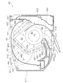
- FIG. 3 is a perspective view illustrating a configuration around an indoor heat exchanger by removing a front panel and the like of the indoor unit in FIG. 2.
- the conceptual diagram of the indoor heat exchanger for demonstrating the normal cooling operation of a multi type air conditioning apparatus.
- the conceptual diagram of the indoor heat exchanger for demonstrating the low-capacity cooling operation of a multi type air conditioning apparatus.
- the graph for demonstrating the concept of the control at the time of low capacity cooling operation.
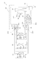
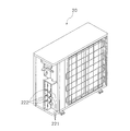
- the circuit diagram showing the schematic structure of the air harmony device concerning modification 1C of the present invention The perspective view which shows the external appearance of the outdoor unit of the modification 1C.
- the refrigerant circuit 11 of the multi-type air conditioner 10 is configured by connecting an outdoor unit 20, indoor units 40, 50, and 60, a liquid refrigerant communication pipe 71, and a gas refrigerant communication pipe 72.
- the refrigerant circuit 11 includes indoor refrigerant circuits 11a, 11b, 11c and an outdoor refrigerant circuit 11d. The refrigerant circulates through the refrigerant circuit 11.
- the operation control device 80 includes a suction pressure sensor 29, a discharge pressure sensor 30, a suction temperature sensor 31, a discharge temperature sensor 32, an outdoor temperature sensor 36, liquid side temperature sensors 44, 54, 64, and gas side temperature sensors 45, 55, 65. It is connected so that it can receive detection signals.
- the operation control device 80 can control the outdoor unit 20 and the indoor units 40, 50, 60 based on these detection signals and the like, the compressor 21, the four-way switching valve 22, the outdoor fan 28, the outdoor unit.
- the expansion valve 38, the indoor expansion valves 41, 51, 61 and the indoor fans 43, 53, 63 are connected.
- Outdoor unit 20 has an outdoor refrigerant circuit 11 d that constitutes a part of the refrigerant circuit 11.
- a compressor 21, a four-way switching valve 22, an outdoor heat exchanger 23, an outdoor expansion valve 38, and an accumulator 24 are connected to the outdoor refrigerant circuit 11d.
- the compressor 21 is a compressor capable of changing the operating capacity, and is a positive displacement compressor driven by a motor 21m whose rotation speed is controlled by an inverter.
- the four-way switching valve 22 is a valve for switching the direction of refrigerant flow.
- the four-way switching valve 22 in FIG. 1 is switched to a connection state indicated by a solid line. That is, the discharge side of the compressor 21 and the outdoor heat exchanger 23 are connected by the four-way switching valve 22, and the suction side (specifically, the accumulator 24) of the compressor 21 and the gas refrigerant communication pipe 72 are connected.
- the outdoor heat exchanger 23 functions as a radiator for the refrigerant compressed by the compressor 21, and the indoor heat exchange is performed as an evaporator for the refrigerant deprived of heat in the outdoor heat exchanger 23.
- the devices 42, 52, 62 function.
- the outdoor heat exchanger 23 is, for example, a cross-fin fin-and-tube heat exchanger, and is a device for exchanging heat between air and a refrigerant in order to use air as a heat source.
- the outdoor heat exchanger 23 has a gas side connected to the four-way switching valve 22 and a liquid side connected to the outdoor expansion valve 38.
- the outdoor expansion valve 38 is downstream of the outdoor heat exchanger 23 in the refrigerant flow direction in the refrigerant circuit 11 when performing a cooling operation in order to adjust the pressure, flow rate, and the like of the refrigerant flowing in the outdoor refrigerant circuit 11d. It is an electric expansion valve arrange
- the outdoor expansion valve 38 is connected to the liquid side of the outdoor heat exchanger 23.
- the outdoor unit 20 has an outdoor fan 28 as a blower for sucking outdoor air into the apparatus and exchanging heat with the refrigerant in the outdoor heat exchanger 23 and then discharging it to the outside.
- the outdoor fan 28 is a fan capable of changing the air volume of air supplied to the outdoor heat exchanger 23, and is, for example, a propeller fan driven by a motor 28m composed of a DC fan motor or the like.
- the outdoor unit 20 includes, for example, a suction pressure sensor 29 that detects a suction pressure of the compressor 21 (that is, a refrigerant pressure corresponding to the evaporation pressure Pe during the cooling operation), and a discharge pressure that detects a discharge pressure of the compressor 21.
- a sensor 30, a suction temperature sensor 31 that detects the suction temperature of the compressor 21, a discharge temperature sensor 32 that detects the discharge temperature of the compressor 21, and the like are provided.
- An outdoor temperature sensor 36 that detects the temperature of the outdoor air that flows into the interior of the outdoor unit 20 is provided at the outdoor air intake port.
- the outdoor unit 20 has an outdoor side control device 37.
- the outdoor control device 37 includes a microcomputer (not shown) provided for controlling the outdoor unit 20, a memory (not shown), an inverter circuit (not shown) for controlling the motor 21m, and the like. is doing.
- the set temperature, set humidity, indoor temperature, indoor humidity, and the like of the plurality of indoor units 40, 50, 60 vary, and since these vary, the capacity required for the outdoor unit 20 is the individual indoor unit 40, It is difficult to adjust to fit all 50,60. Therefore, the outdoor side control device 37 is adapted to some requests of the plurality of indoor units 40, 50, 60, such as the most requested indoor unit of the plurality of indoor units 40, 50, 60, for example.
- the operating capacity of the compressor 21 and / or the air volume of the outdoor fan 28 will be controlled. Therefore, for many of the plurality of indoor units 40, 50, 60, the setting of the operating capacity of the compressor 21 and / or the air volume of the outdoor fan 28 may be higher than necessary.
- Indoor units 40, 50, and 60 are embedded in the ceiling of a room such as a building or suspended, or are hung on the wall surface of a room. For example, it is installed in a room such as a conference room.
- the plurality of indoor units 40, 50, 60 may be arranged in the same room or may be arranged separately in different rooms. Since the indoor unit 40 and the indoor units 50 and 60 have the same configuration, only the configuration of the indoor unit 40 will be described below.
- symbol of the 50th series or the 60th series is attached instead of the code
- the indoor units 40, 50, 60 are connected to the outdoor unit 20 via a liquid refrigerant communication pipe 71 and a gas refrigerant communication pipe 72.
- the indoor unit 40 has an indoor refrigerant circuit 11a (a indoor refrigerant circuit 11b in the indoor unit 50 and an indoor refrigerant circuit 11c in the indoor unit 60) that constitutes a part of the refrigerant circuit 11.
- the indoor refrigerant circuit 11a includes an indoor expansion valve 41 as a decompression mechanism and an indoor heat exchanger 42.
- the indoor expansion valves 41, 51, 61 are provided in the indoor units 40, 50, 60, respectively, as the pressure reducing mechanism.
- the present invention is not limited to this, and a plurality of units corresponding to the indoor units 40, 50, 60 are provided.
- the decompression mechanism may be provided in the outdoor unit 20, or may be provided in a connection unit independent of the indoor units 40, 50, 60 and the outdoor unit 20.
- the indoor expansion valve 41 is an electric expansion valve connected to the liquid side of the indoor heat exchanger 42 in order to adjust the flow rate of the refrigerant flowing in the indoor refrigerant circuit 11a, and blocks passage of the refrigerant. Is also possible.
- the indoor expansion valve 41 is controlled by the indoor control device 47, and is configured to be able to adjust the flow rate of the refrigerant and the pressure reduction by changing the opening degree.
- the indoor heat exchanger 42 is a heat exchanger for exchanging heat between air and a refrigerant, and is, for example, a cross-fin type fin-and-tube heat composed of heat transfer tubes and a large number of fins. It is an exchanger.
- the indoor heat exchanger 42 functions as a refrigerant evaporator during cooling operation to cool room air, and functions as a refrigerant radiator during heating operation to heat room air.
- the indoor unit 40 sucks indoor air into the indoor unit, exchanges heat with the refrigerant in the indoor heat exchanger 42, and then supplies the indoor air 43 as a blower for supplying the indoor air after heat exchange into the room as supply air.
- the indoor fan 43 is a fan capable of changing the air volume supplied to the indoor heat exchanger 42 within a predetermined air volume range. For example, a centrifugal fan or a multiblade fan driven by a motor 43m formed of a DC fan motor or the like. Etc.
- a cross flow fan is used as the indoor fan 43.
- the wall-mounted indoor unit 40 shown in FIG. 2 has an opening of the casing 411, that is, a suction port 431 on the upper side.
- the indoor air sucked from the suction port 431 enters the suction space S1.
- the space on the downstream side of the air filter 412 is also included in the suction space S1.
- An indoor temperature sensor 451 for measuring the temperature of the intake air and an indoor humidity sensor 452 for measuring the relative humidity of the intake air are installed in the intake space S1, for example.
- the temperature measured by the room temperature sensor 451 is the room temperature Tr1 and also the suction temperature Ti.
- the casing 411 forms the outline and frame of the indoor unit 40.
- the rear guider 433 and the stabilizer 434 of the casing 411 form a blowout space S3 that is a blowout flow path following the blowout port 432.
- the air filter 412 is disposed between the suction port 431 and the indoor heat exchanger 42. Prior to passing through the indoor heat exchanger 42, the indoor air passes through the air filter 412 to remove dust. Therefore, the air filter 412 is attached to the casing 411 so as to surround the indoor heat exchanger 42.
- the indoor temperature sensor 451 and the indoor humidity sensor 452 may be provided either upstream or downstream of the air filter 412.
- the indoor heat exchanger 42 includes a front heat exchange unit 421 and a rear heat exchange unit 422.
- the indoor heat exchanger 42 includes a plurality of fins 481 and a plurality of heat transfer tubes 482.
- Each fin 481 is made of a thin metal plate, and is disposed in parallel to the adjacent fin 481 and perpendicular to the longitudinal direction of the indoor unit 40. Therefore, the air passing through the indoor heat exchanger 42 passes between the fins 481 adjacent to each other.
- Each of the plurality of heat transfer tubes 482 is a metal pipe, extends through the fin 481 along the longitudinal direction of the indoor unit 40, and passes through the gap between the refrigerant flowing inside and the fin 481 and the heat transfer tube 482.
- the indoor fan 43 is located between the front heat exchange unit 421 and the rear heat exchange unit 422 and the air outlet 432.
- the indoor fan 43 includes a cylindrical fan rotor 43a that extends long in the longitudinal direction of the indoor unit 40, and a motor 43m that rotates the fan rotor 43a.
- the fan rotor 43a is composed of a plurality of fan blades arranged along the circumference, and the fan rotor 43a rotates clockwise around the center point O in FIG. By rotating around the center point O, an air flow from the front heat exchange unit 421 and the rear heat exchange unit 422 toward the outlet 432 is generated. The air flow toward the air outlet 432 passes through the fan rotor 43a.
- dew condensation occurs when the fan rotor 43a has a temperature lower than the dew point temperature of the mixed air (conditioned air).
- fan rotor condensation occurs downstream of the indoor heat exchanger 42.
- the rotation of the indoor fan 43 is controlled by the indoor side control device 47, and the air volume can be changed according to a command from the indoor side control device 47.
- wing 416 is arrange
- the vertical blades 416 are rotated by a stepping motor (not shown) to adjust the longitudinal wind direction of the indoor unit 40.
- wing 417 is arrange
- the vertical blades 416 and the horizontal blades 417 also form condensation when the temperature is lower than the dew point temperature of the mixed air. Such condensation also corresponds to fan rotor condensation that occurs downstream of the indoor heat exchanger 42.
- the indoor control device 47 is housed in an electrical component box (not shown) installed inside the casing 411.
- the indoor side control device 47 controls the indoor unit 40 in accordance with, for example, an instruction stored in a memory (not shown) and an instruction from a remote controller (not shown).
- the indoor unit 40 is provided with various sensors in addition to the indoor temperature sensor 451 and the indoor humidity sensor 452 described above, but the description of sensors that are not important for the description is omitted here.
- a liquid side temperature sensor 44 that detects the temperature of the refrigerant (the refrigerant temperature corresponding to the evaporation temperature Te during the cooling operation) is provided.
- a gas side temperature sensor 45 that detects the temperature of the refrigerant is provided on the gas side of the indoor heat exchanger 42.
- the blowing space S3 is provided with a blowing temperature sensor 453 that measures the air temperature of the blowing space S3 (the temperature of the mixed air).
- the blowing space S3 is provided with a blowing humidity sensor 454 that measures the air humidity of the blowing space S3 (humidity of the mixed air).
- a thermistor can be used for the liquid side temperature sensor 44, the gas side temperature sensor 45, the indoor temperature sensor 451, and the blowout temperature sensor 453.
- the user individually sets each indoor unit 40, 50, 60 by an input device such as a remote controller in the cooling operation and the heating operation.
- Indoor temperature control for bringing the indoor temperatures Tr1, Tr2, Tr3 closer to the set temperatures Ts1, Ts2, Ts3 is performed on the indoor units 40, 50, 60.
- the indoor fans 43, 53, 63 are set to the automatic air volume mode, the air volume of the indoor fan 43 and the indoor expansion valve 41 are opened so that the indoor temperature Tr1 converges to the set temperature Ts1.
- the air volume of the indoor fan 53 and the opening of the indoor expansion valve 51 are adjusted so that the indoor temperature Tr2 converges to the set temperature Ts2, and the indoor fan 63 is adjusted so that the indoor temperature Tr3 converges to the set temperature Ts3.
- the air volume and the opening degree of the indoor expansion valve 61 are adjusted. In the low-capacity cooling operation mode, the air volume of the indoor fans 43, 53, and 63 is automatically adjusted by the operation control device 80.
- the multi-type air conditioner 10 is configured to perform a cooling operation in the low-capacity cooling operation mode in addition to the normal refrigerant operation mode during the cooling operation.
- the normal cooling operation mode is a mode for performing normal cooling operation
- the low-capacity cooling operation mode is a mode for performing low-capacity cooling operation.
- the low-capacity cooling operation is a cooling operation in which the overheated area of the indoor heat exchanger 42 is increased as compared with the normal cooling operation and the mixed air is mixed with the air that has passed through the overheated area and the air that has passed through the wet area.
- the four-way switching valve 22 is in the state indicated by the solid line in FIG. 1, that is, the discharge side of the compressor 21 is connected to the gas side of the outdoor heat exchanger 23 and the compression
- the suction side of the machine 21 is connected to the gas side of the indoor heat exchangers 42, 52, 62 via the gas refrigerant communication pipe 72.
- the outdoor expansion valve 38 is fully opened during the cooling operation.
- the opening of the indoor expansion valve 41 is adjusted so that the superheat degree SH1 of the refrigerant at the outlet of the indoor heat exchanger 42 (that is, the gas side of the indoor heat exchanger 42) becomes the target superheat degree SHt1, and the indoor expansion valve 51 Is adjusted so that the superheat degree SH2 of the refrigerant at the outlet of the indoor heat exchanger 52 (that is, the gas side of the indoor heat exchanger 52) becomes constant at the target superheat degree SHt2, and the indoor expansion valve 61 is The opening degree is adjusted such that the superheat degree SH3 of the refrigerant at the outlet of the indoor heat exchanger 62 (that is, the gas side of the indoor heat exchanger 62) becomes the target superheat degree SHt3.
- the target superheat degrees SHt1, SHt2, and SHt3 are set to optimal temperature values so that the indoor temperatures Tr1, Tr2, and Tr3 converge to the set temperatures Ts1, Ts2, and Ts3 within a predetermined superheat degree range.
- the superheat degrees SH1, SH2, and SH3 of the refrigerant at the outlets of the indoor heat exchangers 42, 52, and 62 are calculated from the refrigerant temperature values detected by the gas side temperature sensors 45, 55, and 65, for example. , 54, 64 are detected by subtracting the refrigerant temperature value (corresponding to the evaporation temperature Te).
- the superheat degrees SH1, SH2, and SH3 of the refrigerant at the outlets of the indoor heat exchangers 42, 52, and 62 are not limited to being detected by the above-described method.
- the compressor 21, the outdoor fan 28, and the indoor fans 43, 53, 63 are operated in the state of the refrigerant circuit 11, the low-pressure gas refrigerant is sucked into the compressor 21 and compressed to become a high-pressure gas refrigerant. Thereafter, the high-pressure gas refrigerant is sent to the outdoor heat exchanger 23 via the four-way switching valve 22, performs heat exchange with the outdoor air supplied by the outdoor fan 28, and dissipates heat to generate high-pressure liquid refrigerant. Become.
- the high-pressure liquid refrigerant is sent to the indoor units 40, 50 and 60 via the liquid refrigerant communication pipe 71.
- the high-pressure liquid refrigerant sent to the indoor units 40, 50, 60 is decompressed to near the suction pressure of the compressor 21 by the indoor expansion valves 41, 51, 61, respectively, and becomes low-pressure gas-liquid two-phase refrigerant.
- the indoor heat exchangers 42, 52, and 62 exchange heat with indoor air in the indoor heat exchangers 42, 52, and 62, respectively, and evaporate into low-pressure gas refrigerant.
- This low-pressure gas refrigerant is sent to the outdoor unit 20 via the gas refrigerant communication pipe 72 and flows into the accumulator 24 via the four-way switching valve 22. Then, the low-pressure gas refrigerant that has flowed into the accumulator 24 is again sucked into the compressor 21.
- the outdoor heat exchanger 23 is used as a radiator for the refrigerant compressed in the compressor 21, and the indoor heat exchangers 42, 52, and 62 are condensed in the outdoor heat exchanger 23. Then, it is possible to perform a cooling operation to function as an evaporator of the refrigerant sent through the liquid refrigerant communication pipe 71 and the indoor expansion valves 41, 51, 61 after being performed.
- the indoor units 40, 50, 60 do not have a mechanism for adjusting the refrigerant pressure on the gas side of the indoor heat exchangers 42, 52, 62.
- the evaporation pressure Pe in 42, 52 and 62 is a common pressure.
- a superheat region 492 region not hatched
- This overheated region 492 may be referred to as a dry region in the following description.
- the portion near the outlet of the indoor heat exchanger 42 is in the overheat region (dry region) in relation to the overheat control. Sometimes it becomes.
- the opening degree of the indoor expansion valve 41 and the air volume of the indoor fan 43 are adjusted by the operation control device 80, and the low-capacity cooling operation in the state shown in FIG. 5 is performed. It is.
- condensation is more likely to occur in the device downstream of the indoor heat exchanger 42 than in the normal cooling operation in which the condensed water is removed by the indoor heat exchanger 42. Therefore, control for avoiding the occurrence of condensation in the apparatus of the multi-type air conditioner 10, particularly in the indoor unit 40, in the low-performance cooling operation will be described below.
- the indoor unit 40 Since the temperature of the mixed air Ar7 is lowered by expanding the wet area 491 having a higher heat exchange capacity than the overheat area 492, the indoor unit 40 is operated by increasing the opening of the indoor expansion valve 41. The temperature Tr1 can be brought close to the set temperature Ts1. However, if the wet region 491 is excessively expanded in the low-capacity cooling operation, a state in which condensation occurs in the fan rotor 43a of the indoor fan 43 occurs.
- RH100, RH90, RH80, and RH70 are curves indicating relative humidity of 100% RH, 90% RH, 80% RH, and 70% RH, respectively.
- the point P1 in FIG. 6 corresponds to the state of the suction air Ar6.
- the evaporation temperature of the indoor heat exchanger 42 is 7 ° C.
- a point P2 where the dry bulb temperature 7 ° C.
- the intersection of the straight line LN20 connecting the point P1 and the point P2 and the curve RH100 is defined as a point P3. Condensation does not occur if the state of the mixed air Ar7 is in the range D1 from the point P1 to the point P3, but condensation occurs if the state of the mixed air Ar7 is in the range D2 from the point P2 to the point P3.
- the size of the wet region 491 at this point P3 is an upper limit that does not cause condensation. In order to control so as not to exceed the upper limit, the size of the wet region 491 is determined by a method described later.
- the opening degree of the indoor expansion valve 41 and the air volume of the indoor fan 43 are set so that the determined wet area 491 size (occupation ratio of the wet area 491) does not exceed the wet area 491 size at the point P3. Adjust. If the occupation ratio of the wet area 491 during the low-capacity cooling operation approaches the occupation ratio of the wet area 491 at the point P3, the air volume of the indoor fan 43 is increased without opening the indoor expansion valve 41 and the cooling is performed. Control to increase ability.
- (3-4) shows the avoidance control of the fan rotor dew condensation performed by determining the size of the wet area 491 by measuring the temperature or humidity of the mixed air Ar7, and two or more indoor heat exchanger temperatures are shown.
- the fan rotor condensation avoidance control performed by determining the size of the wet region 491 using the detection result of the sensor 455 is shown in (3-5).
- the opening degree of the indoor expansion valve 41 is reduced and / or the air volume of the indoor fan 43 is lowered to lower the cooling capacity.
- the fan rotor condensation is changed to a state that is less likely to occur, and therefore the determination of the size of the wet region 491 may be omitted.
- the size of the wet region 491 is determined using the suction temperature and suction humidity (relative humidity) of the suction air Ar6, the temperature of the mixed air Ar7, and the evaporation temperature, and the determination result of the size of the wet region 491 is used. Control based on.
- the control by the operation control device that calculates the occupation ratio of the wet region 491 and prevents the fan rotor condensation from occurring downstream of the indoor heat exchanger 42 will be described in detail below.
- the suction temperature of the suction air Ar6 is expressed as Ti ° C.
- the suction humidity of the suction air Ar6 is expressed as Hi% RH.
- the temperature of the mixed air Ar7 is expressed as Tm ° C.
- the absolute humidity of the mixed air Ar7 is expressed as Xmkg / kgDA.
- the air temperature of the wet region passing air Ar8 is expressed as Tw ° C.
- the absolute humidity of the wet region passing air Ar8 is expressed as Xwmkg / kgDA.
- the absolute humidity of the overheated area passing air Ar9 is expressed as Xdmkg / kgDA.
- Td the air temperature Td ° C. of the overheated region passing air Ar9 is equal to the suction temperature Ti ° C. Even if such a replacement is used, the accuracy is hardly changed, and by this replacement, a temperature sensor for measuring the air temperature Td ° C. of the overheated region passing air Ar9 can be omitted.
- the operation control device 80 stores information on the bypass factor BF of the indoor heat exchanger 42 in, for example, an internal memory.
- the bypass factor BF is obtained in advance by experiment or simulation, and the obtained value is input to the operation control device 80.
- the operation control device 80 is configured to be able to read and obtain a necessary bypass factor BF from, for example, an internal memory when performing avoidance control of fan rotor condensation during low-performance cooling operation.
- the suction temperature Ti of the suction air Ar6 is detected by the indoor temperature sensor 451.
- the operation control device 80 acquires the value of the suction temperature Ti detected by the room temperature sensor 451 from the room temperature sensor 451.
- the evaporation temperature Te ° C. of the indoor heat exchanger 42 is detected by the liquid side temperature sensor 44.
- the operation control device 80 acquires the value of the evaporation temperature Te detected by the liquid side temperature sensor 44 from the liquid side temperature sensor 44.
- the temperature Tm ° C. of the mixed air Ar 7 is detected by the blowing temperature sensor 453.
- the operation control device 80 acquires the value of the temperature Tm of the mixed air Ar7 detected by the blowing temperature sensor 453 from the liquid side temperature sensor 44.
- the operation control device 80 calculates the value of the air temperature Tw that has passed through the wet region 491 using the following equation (1).
- the operation control device 80 can acquire the value of the air temperature Tw that has passed through the wet region 491 by calculating the equation (1).
- Tw (Ti ⁇ Te) ⁇ BF + Te (1).
- the operation control device 80 calculates the value of the occupation ratio Rw% of the wet region 491 using the following equation (2).
- the operation control device 80 can acquire the value of the occupation ratio Rw of the wet region 491 by calculating the equation (2).
- the operation control device 80 uses the occupation ratio Rw of the wet region 491 to prevent the temperature Tm of the mixed air Ar7 from being lower than the dew point temperature Tp of the mixed air Ar7 using a result obtained by calculation described later. Control is performed so that fan rotor condensation does not occur downstream of the indoor heat exchanger 42. That is, in the low-capacity cooling operation, the operation control device 80 determines the size of the wet region 491 using the temperature Tm of the mixed air Ar7, and the temperature Tm of the mixed air Ar7 exceeds the dew point temperature Tp of the mixed air Ar7. Thus, control is performed so that fan rotor condensation does not occur downstream of the indoor heat exchanger 42.
- the suction humidity Hi of the suction air Ar6 is detected by the indoor humidity sensor 452.
- the operation control device 80 acquires the value of the suction humidity Hi detected by the indoor humidity sensor 452 from the indoor humidity sensor 452.
- the operation control device 80 uses the following equation (3) to calculate the absolute humidity Xd of the air that has passed through the overheating region 492. Calculate the value of.
- the operation control device 80 can acquire the value of the absolute humidity Xd by calculating the equation (3).
- the function fx is, for example, an approximation of an air diagram calculation table by a calculation formula.
- the operation control device 80 calculates the value of the absolute humidity Xw of the air that has passed through the wet region 491 using the following equation (4).
- the operation control device 80 can acquire the value of the occupation ratio Rw of the wet region 491 by calculating the equation (4).
- the operation control device 80 calculates the value of the absolute humidity Xm of the mixed air Ar7 using the following equation (5).
- the operation control device 80 can obtain the value of the absolute humidity Xm of the mixed air Ar7 by calculating the equation (5).
- Xm Rw ⁇ Xw + (1 ⁇ Rw) ⁇ Xd (5).
- Tp fp (Tm, Xm) (6).
- the operation control device 80 prevents the fan rotor condensation on the downstream side of the indoor heat exchanger 42 by preventing the temperature Tm of the mixed air Ar7 from falling below the dew point temperature Tp of the mixed air Ar7 obtained by the equation (6). Control to not.
- FIG. 7 shows a fan rotor dew condensation limit line regarding the temperature of the mixed air, which is obtained from the evaporation temperature, the suction temperature, and the suction temperature.
- the graph shown in FIG. 7 is a schematic representation of the relationship obtained using the above equations (1) to (6).
- the limit lines LN1, LN2, LN3, and LN4 are limit lines when the suction humidity Hi is 85% RH, 80% RH, 70% RH, and 60% RH, respectively. If the temperature Tm of the mixed air Ar7 is higher than these limit lines LN1 to LN4, condensation does not occur. Conversely, if the temperature Tm of the mixed air Ar7 is lower than these limit lines, condensation occurs.
- the temperature of the mixed air Ar7 is made higher than about 17 ° C., thereby avoiding fan rotor condensation.
- the limit lines LN1 to LN4 represent the dew point temperature Tp of the mixed air Ar7 under each condition.
- the indoor unit 40 is operated under the above-described conditions that the evaporation temperature Te is about 7 ° C., the suction humidity Hi is 80% RH, and the dew point temperature Tp of the mixed air Ar7 is about 17 ° C.
- the indoor unit 40 is operated at the operation point OP1 of FIG. In such a case, there is no concern that fan rotor condensation will occur.
- the temperature Tm of the mixed air Ar7 at the operating point OP1 of the indoor unit 40 is higher than 17 ° C., it is possible to perform control to continue the operation as it is, but it is possible to reliably avoid fan rotor condensation.
- the temperature Tm of the mixed air at the operation point OP1 of the indoor unit 40 is higher than 17 ° C., the temperature Tm of the mixed air does not fall below the dew point temperature Tp due to a sudden change in environment or setting conditions. It is conceivable to change the operating condition to an operating point where fan rotor condensation is unlikely to occur.
- the operation control device 80 can detect the temperature Tm of the mixed air Ar7 and the limit line LN2 (dew point temperature). When the temperature difference of (Tp) falls below the first threshold value, the opening of the indoor expansion valve 41, which is a pressure reducing mechanism, may be reduced and the air volume of the indoor fan 43 may be increased. For example, if the first threshold value is 7 ° C., the operation control device 80 determines that (Tm ⁇ Tp) ⁇ 7 ° C. when the temperature Tm of the mixed air Ar7 at the operation point OP1 becomes 23 ° C.
- control is performed to reduce the opening of the indoor expansion valve 41 and increase the air volume of the indoor fan 43.
- the operation control device 80 controls the opening degree of the indoor expansion valve 41 to be small, the refrigerant circulation amount is decreased and the overheating region 492 of the indoor heat exchanger 42 is increased, thereby preventing the temperature Tm of the mixed air from being lowered. , Fan rotor condensation can be suppressed.
- a decrease in the cooling capacity due to a decrease in the refrigerant circulation amount can be compensated by increasing the air volume of the indoor fan 43.
- the operation control device 80 can detect the temperature Tm of the mixed air Ar7 and the limit line LN2 (dew point temperature Tp). When the temperature difference is less than the second threshold value, the air volume of the indoor fan 43 may be controlled to increase. For example, if the second threshold value is 8 ° C., the operation control device 80 determines that (Tm ⁇ Tp) ⁇ 8 ° C. when the temperature Tm of the mixed air Ar7 at the operation point OP1 becomes 24 ° C. Thus, control is performed to increase the air volume of the indoor fan 43.
- the operation control device 80 controls the air volume of the indoor fan 43 to increase, the air volume increases and the cooling capacity increases, so that the superheat region 492 of the indoor heat exchanger 42 changes in the increasing direction.
- the temperature Tm can be prevented from decreasing and the occurrence of fan rotor condensation can be suppressed.
- the operation control device 80 can detect the temperature Tm of the mixed air Ar7 and the limit line LN2 (dew point temperature). When the temperature difference of Tp) falls below the third threshold value, control may be performed to switch from the low-capacity cooling operation mode to the normal cooling operation mode. For example, if the value of the third threshold is 0.5 ° C., the operation control device 80 (Tm ⁇ Tp) ⁇ 0.5 when the temperature Tm of the mixed air Ar7 at the operation point OP1 becomes 17 ° C.
- Control is performed to switch from the low-capacity cooling operation mode to the normal cooling operation mode based on the judgment of ° C.
- the state shown in FIG. 5 changes to the state shown in FIG. 4 to substantially change the indoor heat exchanger. Since the entire area 42 can be made into the wet area 491, air passing through the overheat area 492 of the indoor heat exchanger 42 can be eliminated, so that it is possible to prevent the fan rotor condensation while ensuring the necessary cooling capacity. it can.
- the graph shown in FIG. 8 is a schematic representation of the relationship obtained using the above equations (1) to (6).
- the limit lines LN11, LN12, LN13, and LN14 are limit lines when the suction humidity Hi is 85% RH, 80% RH, 70% RH, and 60% RH, respectively. If the occupation ratio Rw of the wet region 491 is smaller than these limit lines LN11 to LN14, condensation does not occur. Conversely, if the occupation ratio Rw of the wet region 491 is larger than these limit lines LN11 to LN14, condensation occurs.
- the fan rotor condensation can be avoided by making the occupation ratio Rw of the wet region 491 smaller than about 50%. You can see that you can.
- the operation control device 80 is configured so that the indoor unit 40 operates under the above-described conditions that the evaporation temperature Te is about 7 ° C., the suction humidity Hi is 80% RH, and the limit occupation ratio Rmw of the wet region 491 where condensation occurs is about 50 ° C. It is assumed that the indoor unit 40 is in operation and is operated at the operation point OP2 in FIG. In such a case, there is no concern that fan rotor condensation will occur. In such a case, if the occupation ratio Rw of the wet area 491 at the operation point OP2 of the indoor unit 40 is smaller than 50%, it is possible to perform control to continue the operation as it is, but it is possible to reliably avoid fan rotor condensation. Therefore, even if the occupation ratio Rw of the operating point OP2 of the indoor unit 40 is smaller than 50%, it is conceivable to change the operating condition to an operating point where fan rotor condensation is less likely to occur.
- the operation control device 80 indicates that the difference between the occupation ratio Rw of the wet region 491 and the limit line LN12 is the first. It may be configured to perform control to reduce the opening degree of the indoor expansion valve 41 that is a pressure reducing mechanism and increase the air volume of the indoor fan 43 when the value falls below the four threshold values. For example, if the value of the fourth threshold value is 15%, the operation control device 80 determines that (Rmw ⁇ Rw) ⁇ 15 when the occupation ratio Rw of the wet region 491 at the operation point OP2 becomes 40%. Thus, control is performed to reduce the opening of the indoor expansion valve 41 and the air volume of the indoor fan 43 is increased. A decrease in the cooling capacity due to a decrease in the refrigerant circulation amount can be compensated by increasing the air volume of the indoor fan 43.
- the operation control device 80 determines the difference between the occupation ratio Rw of the wet region 491 and the limit line LN12. May be configured to perform control to increase the air volume of the indoor fan 43 when the value falls below the fifth threshold. For example, if the value of the fifth threshold is 25%, the operation control device 80 determines that (Rmw ⁇ Rw) ⁇ 25% when the occupation ratio Rw of the wet region 491 at the operation point OP2 becomes 30%. Then, control for increasing the air volume of the indoor fan 43 is performed.
- the operation control device 80 determines the difference between the occupation ratio Rw of the wet region 491 and the limit line LN12. May be configured to perform control to switch from the low-capacity cooling mode to the normal cooling mode when the value falls below the sixth threshold. For example, if the value of the sixth threshold is 1%, the operation control device 80 determines that (Rmw ⁇ Rm) ⁇ 1% when the occupation ratio Rw of the wet region 491 at the operation point OP2 becomes 50%. Then, control for switching from the low-capacity cooling operation mode to the normal cooling operation mode is performed.
- the operation control device 80 uses the suction temperature Ti, the suction humidity Hi, the humidity of the mixed air Ar7 and the evaporation temperature Te instead of using the suction temperature Ti, the suction humidity Hi, the temperature Tm and the evaporation temperature Te of the mixed air Ar7. Then, the fan rotor condensation avoidance control may be performed so that the fan rotor condensation does not occur downstream of the indoor heat exchanger 42 when the humidity of the mixed air Ar7 exceeds the saturated humidity of the mixed air.
- a blowing humidity sensor 454 may be provided in the blowing space S3.
- Avoidance control of fan rotor dew condensation during low-capacity cooling operation (3-5-1) Overview of avoidance control of fan rotor dew condensation
- the operation control device 80 performs two or more indoor heat exchanges during low-performance cooling operation.
- the size of the wet region 491 is determined using the detection result of the temperature sensor 455, and the temperature of the mixed air Ar7 shown in FIG. 5 exceeds the dew point temperature of the mixed air Ar7, so that the downstream of the indoor heat exchanger 42 In order to prevent the fan rotor condensation from occurring, control is performed.
- the indoor heat exchanger temperature sensors 455 can be arranged before and after each heat transfer tube 482.
- the heat transfer tube 482 is determined to be the wet region 491. It can be constituted as follows. For example, if the indoor heat exchanger temperature sensor 455 on the side near the outlet of the tenth stage heat transfer tube 482 near the outlet of the indoor heat exchanger 42 detects the evaporation temperature Te, the operation control device 80 It is determined that the occupation ratio Rw of 491 is 100%.
- the operation control device 80 can acquire a value that the occupation ratio Rw of the wet region 491 is 50%.
- the indoor heat exchanger temperature sensor 455 may be arrange
- the operation control device 80 can acquire values of the air temperature Tw ° C. that has passed through the wet region 491, the absolute humidity Xwkg / kgDA of the air that has passed through the wet region 491, and the absolute humidity Xdkg / kgDA of the air that has passed through the overheat region 492. It is configured. For example, the operation control device 80 calculates the air temperature Tw that has passed through the wet region 491 and the absolute value of the air that has passed through the wet region 491 by performing calculations of the following equations (14), (15), and (16). The values of the humidity Xw and the absolute humidity Xd of the air that has passed through the overheating region 492 can be acquired.
- the operation control device 80 determines the occupation ratio Rw of the wet region 491 acquired from the detection result of the indoor heat exchanger temperature sensor 455, the acquired temperature Tm of the mixed air Ar7, the absolute humidity Xw of the air that has passed through the wet region 491, and the overheating. Using the value of the absolute humidity Xd of the air that has passed through the region 492, the temperature Tm of the mixed air Ar7 is obtained by the following equation (11).
- Tp fp (Tm, Xm) (13).
- the operation control device 80 uses the result obtained by the equation (13) to prevent the dew point temperature Tp of the mixed air Ar from dropping below the temperature Tm of the mixed air Ar7, thereby reducing the fan downstream of the indoor heat exchanger 42. Control to prevent rotor condensation.
- the operation control device 80 acquires the values of the temperature Tm of the mixed air Ar7, the absolute humidity Xw of the air that has passed through the wet region 491, and the absolute humidity Xd of the air that has passed through the overheat region 492.
- the operation control device 80 reads and acquires the necessary bypass factor BF from, for example, the internal memory, acquires the value of the suction temperature Ti detected by the indoor temperature sensor 451 from the indoor temperature sensor 451,
- the value of the suction humidity Hi detected by the indoor humidity sensor 452 can be acquired from the indoor humidity sensor 452, and the value of the evaporation temperature Te detected by the liquid side temperature sensor 44 can be acquired from the liquid side temperature sensor 44. It is configured.
- Tw (Ti ⁇ Te) ⁇ BF + Te (14).
- the operation control device 80 obtains the absolute humidity Xd of the air that has passed through the overheating region 492 according to the following equation (15).
- fx is a function for obtaining absolute humidity using dry bulb temperature and relative humidity as parameters.
- the absolute humidity Xw of the air that has passed through the wet region is obtained by the following equation (16).
- the operation control device 80 calculates the temperature Tm of the mixed air Ar7, the absolute humidity Xw of the air that has passed through the wet region 491, and the overheating region by calculating the above equations (14), (15), and (16).
- the value of the absolute humidity Xd of the air that has passed through 492 can be acquired.
- FIG. 7 shows the limit line of fan rotor condensation for the temperature of the mixed air obtained from the evaporation temperature, suction temperature, and suction temperature. It is shown.
- the graph shown in FIG. 7 is a schematic representation of the relationship obtained using the above equations (11) to (16). Since the graph in FIG. 7 is also a diagram showing the relationship obtained using the above-described equations (1) to (6), the relationship obtained using the above-described equations (1) to (6) is used.
- the above equations (11) to (16) are used.
- Equipment control for avoiding fan rotor condensation during low-performance cooling operation can be performed using the required relationship.
- the graph shown in FIG. 8 is a schematic representation of the relationship obtained using the above equations (11) to (16). Since the graph of FIG. 8 is also a diagram illustrating the relationship obtained using the above-described equations (1) to (6), the relationship obtained using the above-described equations (1) to (6) is used. In the same way as described above in “(3-4-4) Device control for avoiding fan rotor condensation during low-capacity cooling operation”, the above equations (11) to (16) are used. Equipment control for avoiding fan rotor condensation during low-performance cooling operation can be performed using the required relationship.
- the blower temperature sensor 453 or the blown humidity sensor 454 for measuring the temperature Tm of the mixed air Ar7 or the humidity of the mixed air Ar7 is provided in the indoor unit 40, the wet region using the temperature Tm of the mixed air Ar7 or the humidity of the mixed air Ar7.
- the occupation ratio Rw of 491 can be determined.
- using the temperature Tm of the mixed air Ar7 or the humidity of the mixed air Ar7 it is simply determined whether or not the expansion of the wet region 491 is limited to the upper limit at which no condensation occurs in the fan rotor 43a.
- the certainty of preventing the condensation of the fan rotor 43a is improved.
- the occupation ratio Rw of the wet region 491 can be determined using the detection result of the indoor heat exchanger temperature sensor 455.
- the detection results of two or more indoor heat exchanger temperature sensors 455 it is simply determined whether or not the expansion of the wet region 491 is limited to the upper limit at which no condensation occurs in the fan rotor 43a.
- the certainty of preventing the condensation of the fan rotor 43a is improved.
- the operation control device 80 If the operation control device 80 cannot limit the expansion of the wet area to the upper limit where condensation does not occur on the rotor even if the air volume of the indoor fan 43 is increased in order to obtain the required cooling capacity, the operation control device 80 is in the low-performance cooling operation mode. By switching to the normal cooling operation mode, the entire indoor heat exchanger 42 can be made substantially wet. As a result, air passing through the overheating region 492 of the indoor heat exchanger 42 can be eliminated, and condensation of the fan rotor 43a can be prevented while ensuring necessary cooling capacity.
- the indoor unit 40 is provided with the blowout temperature sensor 453, the blowout humidity sensor 454, and two or more indoor heat exchanger temperature sensors 455. Since the size can be determined, any one of the blowout temperature sensor 453, the blowout humidity sensor 454, and two or more indoor heat exchanger temperature sensors 455 may be provided.
- the multi-type air conditioner 10 includes the indoor expansion valves 41, 51, 61, the liquid side temperature sensors 44, 54, 64, the gas side temperature sensors 45, 55, and the indoor units 40, 50, 60, respectively. Although what 65 was attached was demonstrated, these may be provided in the outdoor unit 20, as FIG.9 and FIG.10 shows.
- the expansion valves 41a, 51a, 61a are provided in the outdoor unit 20, but function as a pressure reducing mechanism for the refrigerant flowing through the indoor heat exchangers 42, 52, 62, respectively.
- Outdoor unit 20 The outdoor unit 20 shown in FIG. 9 and FIG. 10 is different from the outdoor unit 20 shown in FIG. 1 in that the outdoor unit 20 has the expansion valves 41a, 51a, 61a and the liquid side temperature.
- the sensor 44, 54, 64 and the gas side temperature sensor 45, 55, 65 are provided.
- the outdoor unit 20 shown in FIGS. 9 and 10 is shown in FIG. This is the same as the outdoor unit 20.
- the outdoor unit 20 shown in FIGS. 9 and 10 includes three gas side connection ports 221 that are connected to the gas side of the indoor heat exchangers 42, 52, and 62 of the indoor units 40, 50, and 60, respectively. Yes.
- the three gas side connection ports 221 are respectively connected to three other ends of the gas pipe 272 branched into three.
- the refrigerant flowing through the three other ends flows through one end of the gas pipe 272.
- One end of the gas pipe 272 is connected to the four-way switching valve 22.
- One end of the gas pipe 272 is connected to the accumulator 24 during the cooling operation, and is connected to the discharge side of the compressor 21 during the heating operation.
- gas side temperature sensors 45, 55, and 65 are attached to the three other ends, respectively.
- the indoor units 40, 50, 60 shown in FIG. 9 have the same configuration as that of the expansion valves 41a, 51a, 61a, the liquid side temperature sensors 44, 54, 64, and the gas side temperature sensors 45, 55, 65 shown in FIG. Are the same as those of the indoor units 40, 50, 60 shown in FIG.
- the operation control device 80 acquires temperature values detected by the liquid side temperature sensors 44, 54, 64 and the gas side temperature sensors 45, 55, 65, and controls the expansion valves 41a, 51a, 61a via the temperature values.
- 1 is the same as the multi-type air conditioner 10 shown in FIG. 1 and the multi-type air conditioner 10 shown in FIG. 9, and the multi-type air conditioner 10 shown in FIG. The same control as that of the above embodiment can be performed as in the multi-type air conditioner 10 shown in FIG.
- the outdoor expansion valve 38 is omitted.
- the multi-type air conditioner 10 shown in FIG. 9 is not fully contributed to the operation of the cooling operation, and the operations other than the outdoor expansion valve 38 during the cooling operation are also shown in FIG. 1 for the multi-type air conditioner 10 shown in FIG. This can be performed in the same manner as the multi-type air conditioner 10.
- the occupation ratio Rw of the upper limit wet region 491 in which dew condensation does not occur in the apparatus downstream of the indoor heat exchanger 42 of the indoor unit 40 is obtained by calculation using two or more indoor heat exchanger temperature sensors 455.
- the occupation ratio of the wet region 491 where the condensation in the apparatus cannot occur downstream of the indoor heat exchanger 42 in the specified operation range of the specific indoor unit 40 is determined, the condensation in the apparatus occurs.
- the indoor heat exchanger temperature sensor 455 is disposed in a place where it can be determined that the occupancy ratio of the wet region 491 is impossible, and the indoor heat exchanger temperature sensor 455 in the place is overheated during the low-capacity cooling operation period.
- the temperature indicating the region 492 is detected.
- Air conditioning apparatus 20 Outdoor unit 21 Compressor 40, 50, 50 Indoor unit 41, 51, 61 Indoor expansion valve (example of pressure reduction mechanism) 41a, 51a, 61a Expansion valve (example of pressure reducing mechanism) 42, 52, 62 Indoor heat exchanger 43, 53, 63 Indoor fan 80 Operation control device
Landscapes
- Engineering & Computer Science (AREA)
- Physics & Mathematics (AREA)
- Mechanical Engineering (AREA)
- Thermal Sciences (AREA)
- General Engineering & Computer Science (AREA)
- Air Conditioning Control Device (AREA)
- Compression-Type Refrigeration Machines With Reversible Cycles (AREA)
Abstract
マルチ型空気調和装置が低能力冷房運転を行なっているときに、室内ファンのロータで結露が生じるのを防止する。複数の室内機(40,50,60)のうちの少なくとも1つの室内機は、通常冷房運転よりも過熱領域を増やす低能力冷房運転において室内温度が設定温度よりも高いとき、室内膨張弁(41,51,61)の開度を大きくすることにより室内熱交換器(42,52,62)の過熱領域を狭めて湿り領域を拡げる一方、室内ファン(43,53,63)の風量を上げるように構成されている。
Description
本発明は、マルチ型空気調和装置、特に、空気と冷媒との間での熱交換が可能な室内熱交換器を有する複数の室内機を備えるマルチ型空気調和装置に関する。
従来の空気調和装置では、冷房運転時において冷房負荷が低い場合には、例えば特許文献1(特開昭59-122864号公報)に記載されているように、圧縮機の運転周波数を下げて、低い冷房負荷に合わせた運転をすることが行なわれることがある。以下の説明においては、圧縮機の運転周波数を下げて室内ユニットの室内熱交換器の過熱領域を通常冷房運転よりも増やすことで低い冷房負荷に対応させて冷房能力を低下させた運転を低能力冷房運転と呼ぶ。特許文献1に記載されているように、1台の室外ユニットと1台の室内ユニットが接続されている場合には、低能力冷房運転時においても、例えば室内ユニットの室内温度が変化しても、室内ユニットの要求に応えて圧縮機の運転周波数を変更して容易に対応することができる。
ところが、例えば1台の室外機に複数の室内機が接続されて、複数の室内機が並列運転されるマルチ型空気調和装置では、任意の室内機の要求に合わせて室外機の圧縮機の運転周波数を変更することが困難になる。そこで、マルチ型空気調和装置の任意の室内機において、例えば室内温度が変化したり、設定温度が変更されたりして、任意の室内機に要求される冷房能力が変化した場合には、その要求冷房能力が変化した室内機の膨張弁の開度を変化させて、変化した冷房負荷に対処することが考えられる。
しかしながら、マルチ型空気調和装置において低能力冷房運転を行なっているときに、膨張弁の開度を大きくして冷房能力を上げようとすると、室内熱交換器の過熱領域と湿り領域とをそれぞれ通過した空気が混合されることにより室内ファンのロータで結露が発生することがある。
本発明の課題は、マルチ型空気調和装置が低能力冷房運転を行なっているときに、室内ファンのロータで結露が生じるのを防止することである。
本発明の第1観点に係るマルチ型空気調和装置は、冷凍サイクルを行わせるために循環する冷媒を圧縮する圧縮機を有する室外機と、圧縮機から吐出された冷媒が循環する複数の室内熱交換器及び複数の減圧機構を有するとともに複数の室内熱交換器を通った空気が通過する複数の室内ファンを有する複数の室内機と、を備え、複数の室内機のうちの少なくとも1つの室内機は、通常冷房運転よりも過熱領域を増やす低能力冷房運転において室内温度が設定温度よりも高いとき、減圧機構の開度を大きくすることにより室内熱交換器の過熱領域を狭めて湿り領域を拡げる一方、室内ファンの風量を上げるように構成されている。
このマルチ型空気調和装置によると、減圧機構の開度を大きくすることにより室内熱交換器の湿り領域を拡げることで冷房能力が向上する反面、湿り領域が広がると室内熱交換器の過熱領域を通過した空気と湿り領域を通過した空気が混合されてできる混合空気の温度が下がる。そこで、混合空気の温度が混合空気の露点温度以下まで下がりすぎて室内熱交換器の下流で装置内結露が生じないように、減圧機構の開度による制御は室内熱交換器の下流における装置内結露が生じない上限までに止めて湿り領域の拡大を抑え、それ以上の冷房能力の向上を室内ファンの風量を上げることによって必要な冷房能力の確保を行うことができる。それにより、マルチ型空気調和装置が低能力冷房運転を行なっているときに、必要な冷房能力を確保しつつ室内熱交換器の下流において装置内結露が生じるのを防止することができる。
本発明の第2観点に係るマルチ型空気調和装置は、第1観点に係るマルチ型空気調和装置において、少なくとも1つの室内機は、低能力冷房運転において室内温度が設定温度よりも低いとき、減圧機構の開度を小さくするか及び/又は室内ファンの風量を下げて冷房能力を下げることができるように構成されている、ものである。
このマルチ型空気調和装置によると、冷房時の低能力冷房運転において室温が設定温度よりも低い場合には、減圧機構の開度を小さくするか及び/又は室内ファンの風量を下げて冷房能力を下げることから、室内熱交換器の下流で装置内結露が生じない上限までに湿り領域の拡大を制限されている状態から湿り領域を縮小するか及び/又は風量が少なくなる。
本発明の第3観点に係るマルチ型空気調和装置は、第1観点又は第2観点のマルチ型空気調和装置において、少なくとも1つの室内機は、低能力冷房運転時に湿り領域と過熱領域とを通過した混合空気で冷房を行い、混合空気の温度又は混合空気の湿度を用いて室内熱交換器の下流で装置内結露が生じない上限までに湿り領域の拡大が制限されていることを判定する、ものである。
このマルチ型空気調和装置によると、混合空気の温度又は混合空気の湿度を用いて、簡便に、室内熱交換器の下流で装置内結露が生じない上限までに湿り領域の拡大が制限されているか否かを判定することができる。
本発明の第4観点に係るマルチ型空気調和装置は、第1観点から第3観点のいずれかのマルチ型空気調和装置において、少なくとも1つの室内機は、室内熱交換器に室内熱交換器温度センサをさらに有し、低能力冷房運転時に室内熱交換器温度センサの検出結果を用いて室内熱交換器の下流で装置内結露が生じない上限までに湿り領域の拡大が制限されていることを判定する、ものである。
このマルチ型空気調和装置によると、室内熱交換器温度センサの検出結果を用いて、簡便に、室内熱交換器の下流において装置内結露が生じない上限までに湿り領域の拡大が制限されているか否かを判定することができる。
本発明の第5観点に係るマルチ型空気調和装置は、第1観点から第4観点のいずれかのマルチ型空気調和装置において、少なくとも1つの室内機は、必要な冷房能力を得るために、室内ファンの風量を上げて室内熱交換器の下流で装置内結露が生じない上限までに湿り領域の拡大を制限できないときは、低能力冷房運転のモードから通常冷房運転のモードに切り換える、ものである。
このマルチ型空気調和装置によると、低能力冷房運転のモードから通常冷房運転のモードに切り換えることにより、室内熱交換器の全体を湿り領域にすることができることから、室内熱交換器の過熱領域を通過する空気を無くすことができる。
本発明の第1観点に係るマルチ型空気調和装置では、低能力冷房運転を行なっているときに、室内熱交換器の下流で装置内結露が生じるのを防止することができる。
本発明の第2観点に係るマルチ型空気調和装置では、室内熱交換器の下流で装置内結露が生じない状態を維持しながら冷房能力を低下させることができる。
本発明の第3観点又は第4観点に係るマルチ型空気調和装置では、室内熱交換器の下流における装置内結露防止の確実性が向上する。
本発明の第5観点に係るマルチ型空気調和装置では、必要な冷房能力を確保しつつ室内熱交換器の下流で装置内結露を防止することができる。
(1)空気調和装置の全体構成
図1は、本発明の一実施形態に係るマルチ型空気調和装置の概略構成図である。マルチ型空気調和装置10は、蒸気圧縮式の冷凍サイクル運転を行うことによって、ビル等の室内の冷暖房に使用される装置である。マルチ型空気調和装置10は、1台の熱源ユニットとしての室外機20と、それに並列に接続された複数台(本実施形態では、3台)の利用ユニットとしての室内機40,50,60と、室外機20と室内機40,50,60とを接続する冷媒連絡管としての液冷媒連絡管71及びガス冷媒連絡管72とを備えている。
図1は、本発明の一実施形態に係るマルチ型空気調和装置の概略構成図である。マルチ型空気調和装置10は、蒸気圧縮式の冷凍サイクル運転を行うことによって、ビル等の室内の冷暖房に使用される装置である。マルチ型空気調和装置10は、1台の熱源ユニットとしての室外機20と、それに並列に接続された複数台(本実施形態では、3台)の利用ユニットとしての室内機40,50,60と、室外機20と室内機40,50,60とを接続する冷媒連絡管としての液冷媒連絡管71及びガス冷媒連絡管72とを備えている。
マルチ型空気調和装置10の冷媒回路11は、室外機20と、室内機40,50,60と、液冷媒連絡管71及びガス冷媒連絡管72とが接続されることによって構成されている。冷媒回路11は、室内側冷媒回路11a,11b,11c及び室外側冷媒回路11dを含んでいる。冷媒は、冷媒回路11を循環する。
また、マルチ型空気調和装置10は、マルチ型空気調和装置10の全体の運転制御を行う運転制御装置80を備えている。室内側制御装置47,57,67と室外側制御装置37とは、伝送線80aとによって接続されて運転制御装置80を構成している。そして、室内機40,50,60の室内側制御装置47,57,67とは、伝送線80aを介して制御信号等のやりとりを行うことができるようになっている。
運転制御装置80は、吸入圧力センサ29、吐出圧力センサ30、吸入温度センサ31、吐出温度センサ32、室外温度センサ36、液側温度センサ44,54,64及びガス側温度センサ45,55,65などの検出信号を受けることができるように接続されている。また、運転制御装置80は、これらの検出信号等に基づいて室外機20及び室内機40,50,60を制御することができるように圧縮機21、四路切換弁22、室外ファン28、室外膨張弁38、室内膨張弁41,51,61及び室内ファン43,53,63などに接続されている。
(2)詳細構成
(2-1)室外機20
室外機20は、冷媒回路11の一部を構成する室外側冷媒回路11dを有している。この室外側冷媒回路11dには、圧縮機21と、四路切換弁22と、室外熱交換器23と、室外膨張弁38と、アキュムレータ24とが接続されている。
(2-1)室外機20
室外機20は、冷媒回路11の一部を構成する室外側冷媒回路11dを有している。この室外側冷媒回路11dには、圧縮機21と、四路切換弁22と、室外熱交換器23と、室外膨張弁38と、アキュムレータ24とが接続されている。
圧縮機21は、運転容量を可変することが可能な圧縮機であり、インバータにより回転数が制御されるモータ21mによって駆動される容積式圧縮機である。四路切換弁22は、冷媒の流れの方向を切り換えるための弁である。
冷房運転時には、図1の四路切換弁22において、実線で示されている接続状態に切り換えられる。つまり、四路切換弁22によって圧縮機21の吐出側と室外熱交換器23とが接続されるとともに圧縮機21の吸入側(具体的には、アキュムレータ24)とガス冷媒連絡管72とが接続されることになり、冷房運転時には、圧縮機21によって圧縮される冷媒の放熱器として室外熱交換器23が機能し、室外熱交換器23において熱を奪われた冷媒の蒸発器として室内熱交換器42,52,62が機能する。
暖房運転時には、図1の四路切換弁22において、破線で示されている接続状態に切り換えられる。四路切換弁22によって圧縮機21の吐出側とガス冷媒連絡管72側とが接続されるとともに圧縮機21の吸入側と室外熱交換器23が接続されることになり、圧縮機21によって圧縮される冷媒の放熱器として室内熱交換器42,52,62が機能し、室内熱交換器42,52,62において熱を奪われた冷媒の蒸発器として室外熱交換器23が機能する。
室外熱交換器23は、例えばクロスフィン式のフィン・アンド・チューブ型熱交換器であり、空気を熱源とするために空気と冷媒との間の熱交換をさせるための機器である。室外熱交換器23は、そのガス側が四路切換弁22に接続され、その液側が室外膨張弁38に接続されている。
室外膨張弁38は、室外側冷媒回路11d内を流れる冷媒の圧力や流量等の調節を行うために、冷房運転を行う際の冷媒回路11における冷媒の流れ方向において室外熱交換器23の下流側に配置された電動膨張弁である。この室外膨張弁38は、室外熱交換器23の液側に接続されている。
室外機20は、機内に室外空気を吸入して、室外熱交換器23において冷媒と熱交換させた後に、室外に排出するための送風機としての室外ファン28を有している。この室外ファン28は、室外熱交換器23に供給する空気の風量を可変することが可能なファンであり、例えばDCファンモータ等からなるモータ28mによって駆動されるプロペラファン等である。
室外機20には、例えば、圧縮機21の吸入圧力(すなわち、冷房運転時における蒸発圧力Peに対応する冷媒圧力)を検出する吸入圧力センサ29と、圧縮機21の吐出圧力を検出する吐出圧力センサ30と、圧縮機21の吸入温度を検出する吸入温度センサ31と、圧縮機21の吐出温度を検出する吐出温度センサ32などが設けられる。また、室外機20の室外空気の吸入口には、機内に流入する室外空気の温度を検出する室外温度センサ36が設けられる。
さらに、室外機20を構成する各部の動作を制御するために、室外機20は、室外側制御装置37を有している。この室外側制御装置37は、室外機20の制御を行うために設けられたマイクロコンピュータ(図示せず)、メモリ(図示せず)及びモータ21mを制御するインバータ回路(図示せず)などを有している。
複数の室内機40,50,60の設定温度、設定湿度、室内温度及び室内湿度などが区々であり、またそれらが変化するため、室外機20に要求される能力は個々の室内機40,50,60の全てに適合するように調整することは難しい。そこで、室外側制御装置37は、例えば、複数の室内機40,50,60のうちの最も要求の高い室内機など、複数の室内機40,50,60のうちの一部の要求に合わせて圧縮機21の運転容量及び/又は室外ファン28の風量を制御することになる。従って、複数の室内機40,50,60のうちの多くのものにとって、圧縮機21の運転容量及び/又は室外ファン28の風量の設定が必要以上に高くなっている場合がある。
(2-2)室内機
(2-2-1)室内機の概要
室内機40,50,60は、ビル等の室内の天井に埋め込みや吊り下げ等により、または、室内の壁面に壁掛け等により例えば会議室などの部屋に設置される。複数の室内機40,50,60は、同じ部屋に配置されることもあり、異なる部屋に別々に配置されることもある。なお、室内機40と室内機50、60とは同様の構成であるため、以下、室内機40の構成のみについて説明する。室内機50、60の構成については、それぞれ、室内機40の各部を示す40番台の符号の代わりに50番台または60番台の符号を付して、室内機50、60の各部の説明を省略する。
(2-2-1)室内機の概要
室内機40,50,60は、ビル等の室内の天井に埋め込みや吊り下げ等により、または、室内の壁面に壁掛け等により例えば会議室などの部屋に設置される。複数の室内機40,50,60は、同じ部屋に配置されることもあり、異なる部屋に別々に配置されることもある。なお、室内機40と室内機50、60とは同様の構成であるため、以下、室内機40の構成のみについて説明する。室内機50、60の構成については、それぞれ、室内機40の各部を示す40番台の符号の代わりに50番台または60番台の符号を付して、室内機50、60の各部の説明を省略する。
室内機40,50,60は、液冷媒連絡管71及びガス冷媒連絡管72を介して室外機20に接続されている。例えば、室内機40は、冷媒回路11の一部を構成する室内側冷媒回路11a(室内機50では室内側冷媒回路11b、室内機60では室内側冷媒回路11c)を有している。この室内側冷媒回路11aは、減圧機構としての室内膨張弁41と、室内熱交換器42とを有している。なお、本実施形態では、減圧機構として室内機40,50,60それぞれに室内膨張弁41,51,61を設けているが、これに限らずに、室内機40,50,60に対応する複数の減圧機構を室外機20に設けてもよいし、室内機40,50,60や室外機20とは独立した接続ユニットに設けてもよい。
室内膨張弁41は、室内側冷媒回路11a内を流れる冷媒の流量の調節等を行うために、室内熱交換器42の液側に接続された電動膨張弁であり、冷媒の通過を遮断することも可能である。室内膨張弁41は、室内側制御装置47によって制御されており、開度を変更することによって冷媒の流量の調整及び減圧の調整を行うことができるように構成されている。
室内熱交換器42は、空気と冷媒との間の熱交換をさせるための熱交換器であって、例えば伝熱管と多数のフィンとにより構成されたクロスフィン式のフィン・アンド・チューブ型熱交換器である。室内熱交換器42は、冷房運転時には冷媒の蒸発器として機能して室内空気を冷却し、暖房運転時には冷媒の放熱器として機能して室内空気を加熱する。
室内機40は、機内に室内空気を吸入して、室内熱交換器42において冷媒と熱交換させた後に、熱交換後の室内空気を供給空気として室内に供給するための送風機としての室内ファン43を有している。室内ファン43は、室内熱交換器42に供給する空気の風量を所定風量範囲において可変することが可能なファンであり、例えばDCファンモータ等からなるモータ43mによって駆動される遠心ファンや多翼ファン等である。図2に示す室内機40においては、室内ファン43として、クロスフローファンが用いられている。
(2-2-2)室内機の詳細構成
図2には、室内機40の断面が示されている。図2に示されている室内機40は、壁掛け型である。図2において、二点鎖線で示された矢印Ar1は、吸込まれる室内空気の流れを表しており、一点鎖線で示された矢印Ar2は吹き出される調和空気の流れを表している。室内機40は、図2に示されているケーシング411、エアフィルタ412、室内熱交換器42、室内ファン43、垂直羽根416及び水平羽根417を備えている。図3は、図2に示されている室内機40の前側熱交換部421及び後側熱交換部422とその周辺の構成を示す斜視図である。
図2には、室内機40の断面が示されている。図2に示されている室内機40は、壁掛け型である。図2において、二点鎖線で示された矢印Ar1は、吸込まれる室内空気の流れを表しており、一点鎖線で示された矢印Ar2は吹き出される調和空気の流れを表している。室内機40は、図2に示されているケーシング411、エアフィルタ412、室内熱交換器42、室内ファン43、垂直羽根416及び水平羽根417を備えている。図3は、図2に示されている室内機40の前側熱交換部421及び後側熱交換部422とその周辺の構成を示す斜視図である。
図2に示されている壁掛け型の室内機40には、上方にケーシング411の開口部、すなわち吸込口431がある。吸込口431から吸込まれた室内空気は、吸込空間S1に入る。エアフィルタ412の下流側の空間も吸込空間S1に含まれる。吸込み空気の温度を測る室内温度センサ451及び、吸込み空気の相対湿度を測る室内湿度センサ452は、例えば、この吸込空間S1に設置される。この室内温度センサ451が測定する温度が、室内温度Tr1であり、また吸込温度Tiでもある。
室内熱交換器42の下流であって且つ室内ファン43の上流である場所に位置するのが、中間空間S2である。そして、室内ファン43の下流に位置するのが、吹出空間S3である。ケーシング411の上から吸込まれた室内空気は、吸込空間S1から中間空間S2に流れるまでの間にケーシング411内の室内熱交換器42で温度や湿度が調節される。中間空間S2の空気は、室内ファン43を通過するときに混合されて混合空気となり、混合空気は、吹出空間S3を通って下方の吹出口432から調和空気として吹き出される。
(2-2-3)ケーシング411及びエアフィルタ412
このケーシング411によって室内機40の外郭及びフレームが形づくられている。ケーシング411のリアガイダ433及びスタビライザ434によって吹出口432に続く吹出し流路である吹出空間S3が形成されている。エアフィルタ412は、吸込口431と室内熱交換器42との間に配置されている。室内熱交換器42を通過する前に、室内空気は、エアフィルタ412を通過することにより塵埃が除去される。そのため、エアフィルタ412は、室内熱交換器42を囲むように、ケーシング411に取り付けられる。エアフィルタ412の前後で、空気の温度及び湿度の変化は起こらないので、ここでは、エアフィルタ412の前後の空間をともに吸込空間S1として同じように扱う。従って、室内温度センサ451及び室内湿度センサ452は、エアフィルタ412の上流、下流のいずれに設けられてもよい。
このケーシング411によって室内機40の外郭及びフレームが形づくられている。ケーシング411のリアガイダ433及びスタビライザ434によって吹出口432に続く吹出し流路である吹出空間S3が形成されている。エアフィルタ412は、吸込口431と室内熱交換器42との間に配置されている。室内熱交換器42を通過する前に、室内空気は、エアフィルタ412を通過することにより塵埃が除去される。そのため、エアフィルタ412は、室内熱交換器42を囲むように、ケーシング411に取り付けられる。エアフィルタ412の前後で、空気の温度及び湿度の変化は起こらないので、ここでは、エアフィルタ412の前後の空間をともに吸込空間S1として同じように扱う。従って、室内温度センサ451及び室内湿度センサ452は、エアフィルタ412の上流、下流のいずれに設けられてもよい。
(2-2-4)室内熱交換器42
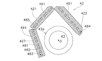
室内熱交換器42は、前側熱交換部421及び後側熱交換部422からなる。室内熱交換器42は、複数のフィン481と複数の伝熱管482を含んでいる。各フィン481は、薄い金属板からなり、隣接するフィン481に対して平行に且つ室内機40の長手方向に対して垂直になるように配置されている。従って、室内熱交換器42を通過する空気は、互いに隣接するフィン481の間を通過する。複数の伝熱管482は、それぞれ、金属製のパイプであり、フィン481を貫いて室内機40の長手方向に沿って延びており、内部を流れる冷媒とフィン481及び伝熱管482の隙間を通過する空気との間で熱のやり取りを行わせるための部材である。冷媒と空気は、多数のフィン481及び多数の伝熱管482を介して熱交換を行う。また、室内空気の中の水分を結露させてフィン481及び伝熱管482に付着させることによって、室内熱交換器42による除湿が可能になる。前側熱交換部421は、前側下方に向かって傾斜する上部前側熱交換部426と、上部前側熱交換部426の下端部から後側下方に向かって傾斜する下部前側熱交換部427とを含んでいる。後側熱交換部422は、後側下方に向かって傾斜している。
室内熱交換器42は、前側熱交換部421及び後側熱交換部422からなる。室内熱交換器42は、複数のフィン481と複数の伝熱管482を含んでいる。各フィン481は、薄い金属板からなり、隣接するフィン481に対して平行に且つ室内機40の長手方向に対して垂直になるように配置されている。従って、室内熱交換器42を通過する空気は、互いに隣接するフィン481の間を通過する。複数の伝熱管482は、それぞれ、金属製のパイプであり、フィン481を貫いて室内機40の長手方向に沿って延びており、内部を流れる冷媒とフィン481及び伝熱管482の隙間を通過する空気との間で熱のやり取りを行わせるための部材である。冷媒と空気は、多数のフィン481及び多数の伝熱管482を介して熱交換を行う。また、室内空気の中の水分を結露させてフィン481及び伝熱管482に付着させることによって、室内熱交換器42による除湿が可能になる。前側熱交換部421は、前側下方に向かって傾斜する上部前側熱交換部426と、上部前側熱交換部426の下端部から後側下方に向かって傾斜する下部前側熱交換部427とを含んでいる。後側熱交換部422は、後側下方に向かって傾斜している。
この実施形態では、説明を簡単にするために、室内熱交換器42の伝熱管482が一列である場合について説明する。しかし、本発明を適用できる室内熱交換器42の伝熱管482の配列は1列である場合に限られず、2列以上であってもよい。また、冷房運転時には、下部前側熱交換部427の最下段の伝熱管483から冷媒が入って後側熱交換部422の最下段の伝熱管484から冷媒が出て行くものとして説明する。そして、各段の伝熱管482は、他の段の伝熱管482と接続されるが、例えば、図3に示されているU字管485によって、異なる段の伝熱管482同士が接続される。この室内熱交換器42において、冷媒は、順に隣接する伝熱管482へと流れる。
(2-2-5)室内ファン43
室内ファン43は、前側熱交換部421及び後側熱交換部422と吹出口432との間に位置する。室内ファン43は、室内機40の長手方向に長く延びる円筒状のファンロータ43aと、ファンロータ43aを回転させるモータ43mとを備えている。ファンロータ43aは、円周に沿って並ぶ複数のファン翼からなっており、ファンロータ43aは、図2において、中心点Oの周りを時計回りに回転する。中心点Oを中心に回転することによって、前側熱交換部421及び後側熱交換部422から吹出口432に向かう空気の流れを発生させる。吹出口432に向かう空気の流れは、ファンロータ43aを貫通する。そのため、ファンロータ43aが混合空気(調和空気)の露点温度よりも低い温度になると結露を生じる。言い換えれば、この場合、室内熱交換器42の下流でファンロータ結露が生じてしまうということである。この室内ファン43は、室内側制御装置47によってその回転が制御されており、室内側制御装置47からの指令に応じて風量を変化させることができる。
室内ファン43は、前側熱交換部421及び後側熱交換部422と吹出口432との間に位置する。室内ファン43は、室内機40の長手方向に長く延びる円筒状のファンロータ43aと、ファンロータ43aを回転させるモータ43mとを備えている。ファンロータ43aは、円周に沿って並ぶ複数のファン翼からなっており、ファンロータ43aは、図2において、中心点Oの周りを時計回りに回転する。中心点Oを中心に回転することによって、前側熱交換部421及び後側熱交換部422から吹出口432に向かう空気の流れを発生させる。吹出口432に向かう空気の流れは、ファンロータ43aを貫通する。そのため、ファンロータ43aが混合空気(調和空気)の露点温度よりも低い温度になると結露を生じる。言い換えれば、この場合、室内熱交換器42の下流でファンロータ結露が生じてしまうということである。この室内ファン43は、室内側制御装置47によってその回転が制御されており、室内側制御装置47からの指令に応じて風量を変化させることができる。
(2-2-6)垂直羽根416及び水平羽根417
垂直羽根416は、吹出空間S3である吹出し流路内に配置されている。垂直羽根416は、ステッピングモータ(図示せず)により回動して、室内機40の長手方向の風向を調節する。水平羽根417は、吹出口432に沿って配置されており、ステッピングモータ(図しせず)により回動して、上下方向の風向を調節する。垂直羽根416及び水平羽根417も、混合空気の露点温度より低い温度になると結露を生じる。このような結露も、室内熱交換器42の下流で生じるファンロータ結露に該当する。
垂直羽根416は、吹出空間S3である吹出し流路内に配置されている。垂直羽根416は、ステッピングモータ(図示せず)により回動して、室内機40の長手方向の風向を調節する。水平羽根417は、吹出口432に沿って配置されており、ステッピングモータ(図しせず)により回動して、上下方向の風向を調節する。垂直羽根416及び水平羽根417も、混合空気の露点温度より低い温度になると結露を生じる。このような結露も、室内熱交換器42の下流で生じるファンロータ結露に該当する。
(2-2-7)室内側制御装置47及び各種センサ
室内側制御装置47は、ケーシング411の内部に設置されている電装品箱(図示せず)に収納されている。室内側制御装置47は、例えばメモリ(図示せず)に記憶されている指示及びリモートコントローラ(図示せず)からの指示に従って室内機40の制御を行う。
室内側制御装置47は、ケーシング411の内部に設置されている電装品箱(図示せず)に収納されている。室内側制御装置47は、例えばメモリ(図示せず)に記憶されている指示及びリモートコントローラ(図示せず)からの指示に従って室内機40の制御を行う。
室内機40には、上述の室内温度センサ451及び室内湿度センサ452以外にも各種のセンサが設けられているが、ここでは、説明にとって重要でないセンサの記載は省略している。室内熱交換器42の液側には、冷媒の温度(冷房運転時における蒸発温度Teに対応する冷媒温度)を検出する液側温度センサ44が設けられている。また、室内熱交換器42のガス側には、冷媒の温度を検出するガス側温度センサ45が設けられている。吹出空間S3には、吹出空間S3の空気温度(混合空気の温度)を測定する吹出温度センサ453が設けられている。また、吹出空間S3には、吹出空間S3の空気湿度(混合空気の湿度)を測定する吹出湿度センサ454が設けられる。液側温度センサ44、ガス側温度センサ45、室内温度センサ451及び吹出温度センサ453には、例えばサーミスタを用いることができる。
(3)空気調和装置の動作
マルチ型空気調和装置10では、冷房運転及び暖房運転において、利用者がリモートコントローラ等の入力装置により、それぞれの室内機40,50,60に個別に設定している設定温度Ts1、Ts2,Ts3に室内温度Tr1、Tr2,Tr3を近づける室内温度制御を、各室内機40,50,60に対して行っている。この室内温度制御では、室内ファン43,53,63が風量自動モードに設定されている場合には、設定温度Ts1に室内温度Tr1が収束するように室内ファン43の風量及び室内膨張弁41の開度が調整され、設定温度Ts2に室内温度Tr2が収束するように室内ファン53の風量及び室内膨張弁51の開度が調整され、設定温度Ts3に室内温度Tr3が収束するように室内ファン63の風量及び室内膨張弁61の開度が調整される。低能力冷房運転モードでは、室内ファン43,53,63の風量が運転制御装置80により自動的に調整される。
マルチ型空気調和装置10では、冷房運転及び暖房運転において、利用者がリモートコントローラ等の入力装置により、それぞれの室内機40,50,60に個別に設定している設定温度Ts1、Ts2,Ts3に室内温度Tr1、Tr2,Tr3を近づける室内温度制御を、各室内機40,50,60に対して行っている。この室内温度制御では、室内ファン43,53,63が風量自動モードに設定されている場合には、設定温度Ts1に室内温度Tr1が収束するように室内ファン43の風量及び室内膨張弁41の開度が調整され、設定温度Ts2に室内温度Tr2が収束するように室内ファン53の風量及び室内膨張弁51の開度が調整され、設定温度Ts3に室内温度Tr3が収束するように室内ファン63の風量及び室内膨張弁61の開度が調整される。低能力冷房運転モードでは、室内ファン43,53,63の風量が運転制御装置80により自動的に調整される。
本発明にとって重要なのは低能力冷房運転であり、暖房運転は従来と同じ構成としてよいため、以下においては専ら冷房運転について説明する。マルチ型空気調和装置10は、冷房運転時において、通常冷媒運転モード以外に、低能力冷房運転モードで冷房運転が行なえるように構成されている。通常冷房運転モードは通常冷房運転を行なうモードであり、低能力冷房運転モードは低能力冷房運転を行なうモードである。低能力冷房運転は、通常冷房運転よりも室内熱交換器42の過熱領域を増やして過熱領域を通過した空気と湿り領域を通過した空気とを混合した混合空気で冷房する冷房運転である。
(3-1)冷房運転
冷房運転時は、四路切換弁22が図1の実線で示される状態、すなわち、圧縮機21の吐出側が室外熱交換器23のガス側に接続され、かつ、圧縮機21の吸入側がガス冷媒連絡管72を介して室内熱交換器42,52,62のガス側に接続された状態となっている。この場合には冷房運転時に、室外膨張弁38は、全開状態にされている。室内膨張弁41は、室内熱交換器42の出口(すなわち、室内熱交換器42のガス側)における冷媒の過熱度SH1が目標過熱度SHt1になるように開度が調節され、室内膨張弁51は、室内熱交換器52の出口(すなわち、室内熱交換器52のガス側)における冷媒の過熱度SH2が目標過熱度SHt2で一定になるように開度が調節され、室内膨張弁61は、室内熱交換器62の出口(すなわち、室内熱交換器62のガス側)における冷媒の過熱度SH3が目標過熱度SHt3になるように開度が調節されるようになっている。
冷房運転時は、四路切換弁22が図1の実線で示される状態、すなわち、圧縮機21の吐出側が室外熱交換器23のガス側に接続され、かつ、圧縮機21の吸入側がガス冷媒連絡管72を介して室内熱交換器42,52,62のガス側に接続された状態となっている。この場合には冷房運転時に、室外膨張弁38は、全開状態にされている。室内膨張弁41は、室内熱交換器42の出口(すなわち、室内熱交換器42のガス側)における冷媒の過熱度SH1が目標過熱度SHt1になるように開度が調節され、室内膨張弁51は、室内熱交換器52の出口(すなわち、室内熱交換器52のガス側)における冷媒の過熱度SH2が目標過熱度SHt2で一定になるように開度が調節され、室内膨張弁61は、室内熱交換器62の出口(すなわち、室内熱交換器62のガス側)における冷媒の過熱度SH3が目標過熱度SHt3になるように開度が調節されるようになっている。
なお、目標過熱度SHt1,SHt2,SHt3は、所定の過熱度範囲の内で室内温度Tr1,Tr2,Tr3が設定温度Ts1,Ts2,Ts3に収束するために最適な温度値に設定される。各室内熱交換器42,52,62の出口における冷媒の過熱度SH1,SH2,SH3は、例えば、各ガス側温度センサ45,55,65により検出される冷媒温度値から各液側温度センサ44,54,64により検出される冷媒温度値(蒸発温度Teに対応)を差し引くことによってそれぞれ検出される。ただし、各室内熱交換器42,52,62の出口における冷媒の過熱度SH1、SH2,SH3は、上述の方法で検出することに限られない。
この冷媒回路11の状態で、圧縮機21、室外ファン28及び室内ファン43,53,63を運転すると、低圧のガス冷媒は、圧縮機21に吸入されて圧縮されて高圧のガス冷媒となる。その後、高圧のガス冷媒は、四路切換弁22を経由して室外熱交換器23に送られて、室外ファン28によって供給される室外空気と熱交換を行って放熱して高圧の液冷媒となる。そして、この高圧の液冷媒は、液冷媒連絡管71を経由して、室内機40,50,60に送られる。
この室内機40,50,60に送られた高圧の液冷媒は、室内膨張弁41,51,61によってそれぞれ圧縮機21の吸入圧力近くまで減圧されて低圧の気液二相状態の冷媒となって室内熱交換器42,52,62に送られ、室内熱交換器42,52,62においてそれぞれ室内空気と熱交換を行って蒸発して低圧のガス冷媒となる。
この低圧のガス冷媒は、ガス冷媒連絡管72を経由して室外機20に送られ、四路切換弁22を経由して、アキュムレータ24に流入する。そして、アキュムレータ24に流入した低圧のガス冷媒は、再び、圧縮機21に吸入される。このように、マルチ型空気調和装置10では、室外熱交換器23を圧縮機21において圧縮される冷媒の放熱器として、かつ、室内熱交換器42,52,62を室外熱交換器23において凝縮された後に液冷媒連絡管71及び室内膨張弁41,51,61を通じて送られる冷媒の蒸発器としてそれぞれ機能させる冷房運転を行うことが可能である。なお、マルチ型空気調和装置10では、室内熱交換器42,52,62のガス側に冷媒の圧力を調整する機構が室内機40,50,60のそれぞれにないため、全ての室内熱交換器42,52,62における蒸発圧力Peが共通の圧力となる。
(3-2)通常冷房運転と低能力冷房運転
通常冷房運転では、図4に示されているように、室内熱交換器42の実質的に全ての部分が湿り領域491(斜線が描かれている領域)となっている。それに対して、低能力冷房運転では、図5に示されているように、冷媒の入口に最も近い下部前側熱交換部427の最下段の伝熱管483から上部前側熱交換部426の下から4段目の伝熱管486までが湿り領域491(斜線が描かれている領域)となっている。しかし、上部前側熱交換部426の下から5段目の伝熱管487から後側熱交換部422の最下段の伝熱管484までが過熱領域492(斜線が描かれていない領域)となっている。この過熱領域492は、以下の説明で乾き領域と呼ぶこともある。なお、通常冷房運転では、高い冷房能力を得るために、ほぼ全体が湿り領域491になるが、過熱制御との関係で、室内熱交換器42の出口に近い部分が過熱領域(乾き領域)になる場合もある。
通常冷房運転では、図4に示されているように、室内熱交換器42の実質的に全ての部分が湿り領域491(斜線が描かれている領域)となっている。それに対して、低能力冷房運転では、図5に示されているように、冷媒の入口に最も近い下部前側熱交換部427の最下段の伝熱管483から上部前側熱交換部426の下から4段目の伝熱管486までが湿り領域491(斜線が描かれている領域)となっている。しかし、上部前側熱交換部426の下から5段目の伝熱管487から後側熱交換部422の最下段の伝熱管484までが過熱領域492(斜線が描かれていない領域)となっている。この過熱領域492は、以下の説明で乾き領域と呼ぶこともある。なお、通常冷房運転では、高い冷房能力を得るために、ほぼ全体が湿り領域491になるが、過熱制御との関係で、室内熱交換器42の出口に近い部分が過熱領域(乾き領域)になる場合もある。
湿り領域491には、気液二相状態の冷媒が流れており、過熱領域492では、ガス状態の冷媒が流れている。そのため、過熱領域492では、冷媒と空気との間での熱交換がほとんど行われず、過熱領域492を通過した空気の温度は、通過する前の空気の温度と実質的に同じになる。
低能力冷房運転モードが選択されると、運転制御装置80により、室内膨張弁41の開度と室内ファン43の風量が調整され、図5に示されている状態での低能力冷房運転が行なわれる。低能力冷房運転では、室内熱交換器42で結露水が取除かれる通常冷房運転に比べて、室内熱交換器42の下流の装置内で結露が発生し易い。そこで、以下に、低能力冷房運転においてマルチ型空気調和装置10の装置内、特に室内機40の機内で結露が発生するのを回避するための制御について説明する。
(3-3)低能力冷房運転時の制御
(3-3-1)低能力冷房運転時の制御の概要
図5に示されている複数の矢印は、それぞれ、吸込み空気Ar6、混合空気Ar7、湿り領域通過空気Ar8及び過熱領域通過空気Ar9を概念的に示している。運転制御装置80は、低能力冷房運転時において、室内温度Tr1が設定温度Ts1よりも高いとき、室内膨張弁41の開度を大きくすることにより、過熱領域492を狭めて湿り領域491を拡げる制御を行う。ここで、室内温度Tr1の値は、吸込み空気Ar6の吸込温度Tiの値であり、室内温度センサ451によって計測されて運転制御装置80に送信される。
(3-3-1)低能力冷房運転時の制御の概要
図5に示されている複数の矢印は、それぞれ、吸込み空気Ar6、混合空気Ar7、湿り領域通過空気Ar8及び過熱領域通過空気Ar9を概念的に示している。運転制御装置80は、低能力冷房運転時において、室内温度Tr1が設定温度Ts1よりも高いとき、室内膨張弁41の開度を大きくすることにより、過熱領域492を狭めて湿り領域491を拡げる制御を行う。ここで、室内温度Tr1の値は、吸込み空気Ar6の吸込温度Tiの値であり、室内温度センサ451によって計測されて運転制御装置80に送信される。
過熱領域492よりも熱交換能力の高い湿り領域491が拡がることにより、混合空気Ar7の温度が低くなるので、室内膨張弁41の開度を大きくして室内機40が運転されることにより、室内温度Tr1を設定温度Ts1に近づけることができる。しかしながら、低能力冷房運転において、湿り領域491を拡げ過ぎると、室内ファン43のファンロータ43aで結露を生じる状態が発生する。
ここで、湿り領域491を拡げ過ぎるとファンロータ43aで結露を生じる状態になることを、図6に示されている空気線図計算表を用いて説明する。図6においては、RH100、RH90,RH80,RH70が、それぞれ相対湿度100%RH、90%RH、80%RH、70%RHを示す曲線である。吸込み空気Ar6の吸込温度が27℃で、相対湿度が約85%RHであるとすると、図6の点P1が吸込み空気Ar6の状態に対応する。室内熱交換器42の蒸発温度が7℃とすると、乾球温度7℃と曲線RH100(飽和線)とが交わる点P2を取る。そして、点P1と点P2とを結んだ直線LN20と曲線RH100との交点を点P3とする。混合空気Ar7の状態が点P1から点P3までの範囲D1に入っていれば結露を生じないが、混合空気Ar7の状態が点P2から点P3までの範囲D2に入っていれば結露を生じる。この点P3のときの湿り領域491の大きさが、結露を生じない上限になる。この上限を超えないように制御するために、後述する方法などによって湿り領域491の大きさを判定する。そして、判定した湿り領域491の大きさ(湿り領域491の占有割合)が点P3のときの湿り領域491の大きさを超えないように、室内膨張弁41の開度と室内ファン43の風量を調節する。低能力冷房運転中の湿り領域491の占有割合が点P3の湿り領域491の占有割合に近づいてくれば、室内膨張弁41の開度を開けずに、室内ファン43の風量を上げることで冷房能力を上げるように制御する。
以下においては、混合空気Ar7の温度又は湿度を測定することによって湿り領域491の大きさを判定して行うファンロータ結露の回避制御を(3-4)に示し、2以上の室内熱交換器温度センサ455の検出結果を用いて湿り領域491の大きさを判定して行うファンロータ結露の回避制御を(3-5)に示す。
なお、低能力冷房運転において室内温度Tr1が設定温度Ts1よりも低いときは、室内膨張弁41の開度を小さくするか及び/又は室内ファン43の風量を下げて冷房能力を下げる。室内温度Tr1が設定温度Ts1よりも低い場合に対応させる制御ではファンロータ結露がさらに生じ難い状態に変化させるため、湿り領域491の大きさの判定を省いてもよい。
(3-4)低能力冷房運転時の回避制御
(3-4-1)ファンロータ結露の回避制御の概要
図5に示されている複数の矢印は、それぞれ、吸込み空気Ar6、混合空気Ar7、湿り領域通過空気Ar8及び過熱領域通過空気Ar9を概念的に示している。運転制御装置80は、低能力冷房運転時に、混合空気Ar7の温度を用いて湿り領域491の大きさを判定し、混合空気Ar7の温度が混合空気Ar7の露点温度を超えることによって室内熱交換器42の下流でファンロータ結露が発生する状況になるのを防止する制御を行う。さらに詳細には、吸込み空気Ar6の吸込温度と吸込湿度(相対湿度)、混合空気Ar7の温度及び蒸発温度を用いて湿り領域491の大きさを判定し、湿り領域491の大きさの判定結果に基づいて制御する。湿り領域491の大きさ(湿り領域491の面積)は、例えば、(湿り領域491の面積)÷((湿り領域491の面積)+(過熱領域492の面積))×100(=湿り領域491の占有割合)で定量化される。つまり、湿り領域491の占有割合を計算することによって、湿り領域491の大きさを判定することができる。湿り領域491の占有割合を計算して室内熱交換器42の下流でファンロータ結露が発生する状況になるのを防止する運転制御装置による制御については、以下に詳述する。
(3-4-1)ファンロータ結露の回避制御の概要
図5に示されている複数の矢印は、それぞれ、吸込み空気Ar6、混合空気Ar7、湿り領域通過空気Ar8及び過熱領域通過空気Ar9を概念的に示している。運転制御装置80は、低能力冷房運転時に、混合空気Ar7の温度を用いて湿り領域491の大きさを判定し、混合空気Ar7の温度が混合空気Ar7の露点温度を超えることによって室内熱交換器42の下流でファンロータ結露が発生する状況になるのを防止する制御を行う。さらに詳細には、吸込み空気Ar6の吸込温度と吸込湿度(相対湿度)、混合空気Ar7の温度及び蒸発温度を用いて湿り領域491の大きさを判定し、湿り領域491の大きさの判定結果に基づいて制御する。湿り領域491の大きさ(湿り領域491の面積)は、例えば、(湿り領域491の面積)÷((湿り領域491の面積)+(過熱領域492の面積))×100(=湿り領域491の占有割合)で定量化される。つまり、湿り領域491の占有割合を計算することによって、湿り領域491の大きさを判定することができる。湿り領域491の占有割合を計算して室内熱交換器42の下流でファンロータ結露が発生する状況になるのを防止する運転制御装置による制御については、以下に詳述する。
(3-4-2)ファンロータ結露の回避制御における計算
以下の説明では、吸込み空気Ar6の吸込温度はTi℃と表され、吸込み空気Ar6の吸込湿度はHi%RHと表される。混合空気Ar7の温度はTm℃と表され、混合空気Ar7の絶対湿度はXmkg/kgDAと表される。湿り領域通過空気Ar8の空気温度はTw℃と表され、湿り領域通過空気Ar8の絶対湿度はXwmkg/kgDAと表される。過熱領域通過空気Ar9の空気温度Td℃と表され、過熱領域通過空気Ar9の絶対湿度はXdmkg/kgDAと表される。ただし、過熱領域通過空気Ar9の空気温度Td℃が吸込温度Ti℃と等しいものとして、Tdの代わりにTiを用いて表すことができる。このように置き換えてもほとんど精度が変わらず、このように置き換えることで、過熱領域通過空気Ar9の空気温度Td℃を測定するための温度センサを省くことができる。
以下の説明では、吸込み空気Ar6の吸込温度はTi℃と表され、吸込み空気Ar6の吸込湿度はHi%RHと表される。混合空気Ar7の温度はTm℃と表され、混合空気Ar7の絶対湿度はXmkg/kgDAと表される。湿り領域通過空気Ar8の空気温度はTw℃と表され、湿り領域通過空気Ar8の絶対湿度はXwmkg/kgDAと表される。過熱領域通過空気Ar9の空気温度Td℃と表され、過熱領域通過空気Ar9の絶対湿度はXdmkg/kgDAと表される。ただし、過熱領域通過空気Ar9の空気温度Td℃が吸込温度Ti℃と等しいものとして、Tdの代わりにTiを用いて表すことができる。このように置き換えてもほとんど精度が変わらず、このように置き換えることで、過熱領域通過空気Ar9の空気温度Td℃を測定するための温度センサを省くことができる。
運転制御装置80は、例えば内部メモリに、室内熱交換器42のバイパスファクタBFに関する情報を記憶している。バイパスファクタBFは、予め実験又はシミュレーションによって求められ、求められた値が運転制御装置80に入力されている。運転制御装置80は、低能力冷房運転時のファンロータ結露の回避制御を行う際に、必要なバイパスファクタBFを、例えば内部メモリから読み出して取得することができるように構成されている。
既に説明したように、吸込み空気Ar6の吸込温度Tiは、室内温度センサ451により検出される。運転制御装置80は、室内温度センサ451で検出された吸込温度Tiの値を室内温度センサ451から取得する。
室内熱交換器42の蒸発温度Te℃は、液側温度センサ44により検出される。運転制御装置80は、液側温度センサ44で検出された蒸発温度Teの値を液側温度センサ44から取得する。
混合空気Ar7の温度Tm℃は、吹出温度センサ453により検出される。運転制御装置80は、吹出温度センサ453で検出された混合空気Ar7の温度Tmの値を液側温度センサ44から取得する。
運転制御装置80は、次の(1)式を用いて、湿り領域491を通過した空気温度Twの値を計算する。運転制御装置80は、この(1)式の計算によって、湿り領域491を通過した空気温度Twの値を取得することができる。
Tw=(Ti-Te)×BF+Te・・・(1)。
運転制御装置80は、次の(2)式を用いて、湿り領域491の占有割合Rw%の値を計算する。運転制御装置80は、この(2)式の計算によって、湿り領域491の占有割合Rwの値を取得することができる。
Rw=(Tm-Ti)/(Tw-Ti)・・・(2)。
運転制御装置80は、湿り領域491の占有割合Rwを使って、後述する計算によって求められる結果を用いて混合空気Ar7の温度Tmが混合空気Ar7の露点温度Tpを下回らないようにすることにより、室内熱交換器42の下流でファンロータ結露が生じないように制御する。つまり、運転制御装置80は、低能力冷房運転においては、混合空気Ar7の温度Tmを用いて湿り領域491の大きさを判定し、混合空気Ar7の温度Tmが混合空気Ar7の露点温度Tpを超えることによって室内熱交換器42の下流でファンロータ結露が生じないように制御を行う。
次に、湿り領域491の占有割合Rwを使って、混合空気Ar7の温度Tmと混合空気Ar7の露点温度Tpとの関係を求める方法について説明する。
吸込み空気Ar6の吸込湿度Hiは、室内湿度センサ452により検出される。運転制御装置80は、室内湿度センサ452で検出された吸込湿度Hiの値を室内湿度センサ452から取得する。
乾球温度と相対湿度をパラメータとして絶対湿度を求める関数がfxと表される場合において、運転制御装置80は、次の(3)式を用いて、過熱領域492を通過した空気の絶対湿度Xdの値を計算する。運転制御装置80は、この(3)式の計算によって、絶対湿度Xdの値を取得することができる。関数fxは、例えば、空気線図計算表を計算式で近似したものである。
Xd=fx(Ti,Hi)・・・(3)。
運転制御装置80は、次の(4)式を用いて、湿り領域491を通過した空気の絶対湿度Xwの値を計算する。運転制御装置80は、この(4)式の計算によって、湿り領域491の占有割合Rwの値を取得することができる。
Xw=(Xd-fx(Te,100))×BF+fx(Te,100)・・・(4)。
運転制御装置80は、次の(5)式を用いて、混合空気Ar7の絶対湿度Xmの値を計算する。運転制御装置80は、この(5)式の計算によって、混合空気Ar7の絶対湿度Xmの値を取得することができる。
Xm=Rw×Xw+(1-Rw)×Xd・・・(5)。
乾球温度と絶対湿度とをパラメータとして露点温度を求める関数がfpと表される場合において、運転制御装置80は、次の(6)式を用いて、混合空気Ar7の露点温度Tpの値を計算する。関数fpは、例えば、空気線図計算表を計算式で近似したものである。運転制御装置80は、この(6)式の計算によって、混合空気Ar7の露点温度Tpの値を取得することができる。
Tp=fp(Tm,Xm)・・・(6)。
運転制御装置80は、(6)式により求められた混合空気Ar7の露点温度Tpを混合空気Ar7の温度Tmが下回らないようにすることにより、室内熱交換器42の下流でファンロータ結露が生じないように制御する。
(3-4-3)低能力冷房運転時のファンロータ結露回避のための機器制御
上述の(1)式から(6)式を用いて求められる湿り領域の大きさ(湿り領域の占有割合)に基づいて算出される計算結果を使って、低能力冷房運転時のファンロータ結露回避のための機器制御が行われる。例えば、混合空気Ar7の温度Tm(吹出温度センサ453が検出した温度)と、上述の(1)式から(6)式を用いて求められる混合空気Ar7の露点温度Tpとを比較することによって、運転制御装置80は、室内膨張弁41及び/又は室内ファン43を制御する。
上述の(1)式から(6)式を用いて求められる湿り領域の大きさ(湿り領域の占有割合)に基づいて算出される計算結果を使って、低能力冷房運転時のファンロータ結露回避のための機器制御が行われる。例えば、混合空気Ar7の温度Tm(吹出温度センサ453が検出した温度)と、上述の(1)式から(6)式を用いて求められる混合空気Ar7の露点温度Tpとを比較することによって、運転制御装置80は、室内膨張弁41及び/又は室内ファン43を制御する。
図7には、蒸発温度と吸込温度と吸込温度から求まる、混合空気の温度についてのファンロータ結露の限界ラインが示されている。図7に示されているグラフは、上述の(1)式から(6)式を用いて求められる関係を図式化したものである。限界ラインLN1、LN2,LN3,LN4は、それぞれ、吸込湿度Hiが85%RHの場合、80%RHの場合、70%RHの場合、60%RHの場合の限界ラインである。これらの限界ラインLN1~LN4よりも混合空気Ar7の温度Tmが高ければ、結露は生じない。逆に言うと、これらの限界ラインよりも混合空気Ar7の温度Tmが低ければ、結露が生じる。
図7を用いて、例えば、蒸発温度Teが約7℃で、吸込湿度Hiが80%RHであれば、混合空気Ar7の温度Tmを約17℃よりも高くすることでファンロータ結露を回避することができることが分かる。言い換えると、この限界ラインLN1~LN4は、各条件における混合空気Ar7の露点温度Tpを表しているということである。
運転制御装置80は、蒸発温度Teが約7℃で、吸込湿度Hiが80%RHで、混合空気Ar7の露点温度Tpが約17℃になるという前述の条件で室内機40が運転されていて、且つ室内機40が図7の運転ポイントOP1で運転されているとする。このような場合には、ファンロータ結露が発生する心配はない。このような場合に、室内機40の運転ポイントOP1の混合空気Ar7の温度Tmが17℃より高いならそのままの運転を続けるという制御を行うことも可能であるが、ファンロータ結露を確実に回避するために、室内機40の運転ポイントOP1の混合空気の温度Tmが17℃よりも高くても、急激な環境や設定条件の変化によって混合空気の温度Tmが露点温度Tpを下回らないように、よりファンロータ結露が生じ難い運転ポイントに運転条件を変更することが考えられる。
また、運転制御装置80は、例えば、前述の条件で蒸発温度Teが約7℃且つ吸込湿度Hiが80%RHで変化していない場合に、混合空気Ar7の温度Tmと限界ラインLN2(露点温度Tp)の温度差が第1閾値を下回ったときに、減圧機構である室内膨張弁41の開度を小さくするとともに室内ファン43の風量を増加させる制御を行うように構成されてもよい。例えば、第1閾値の値を7℃としていれば、運転制御装置80は、運転ポイントOP1の混合空気Ar7の温度Tmが23℃になった場合には(Tm-Tp)<7℃と判断して、室内膨張弁41の開度を小さくするとともに室内ファン43の風量を増加させる制御を行う。運転制御装置80が室内膨張弁41の開度を小さくするように制御すると、冷媒循環量が下がって室内熱交換器42の過熱領域492が大きくなるので、混合空気の温度Tmの低下を防いで、ファンロータ結露の発生を抑制できる。冷媒循環量が下がることによる冷房能力の低下は室内ファン43の風量を増加させることによって補うことができる。
運転制御装置80は、例えば、前述の条件で蒸発温度Teが約7℃且つ吸込湿度Hiが80%RHで変化していない場合に、混合空気Ar7の温度Tmと限界ラインLN2(露点温度Tp)の温度差が第2閾値を下回ったときに、室内ファン43の風量を増加させる制御を行うように構成されてもよい。例えば、第2閾値の値を8℃としていれば、運転制御装置80は、運転ポイントOP1の混合空気Ar7の温度Tmが24℃になった場合には(Tm-Tp)<8℃と判断して、室内ファン43の風量を増加させる制御を行う。運転制御装置80が室内ファン43の風量を増加させるように制御すると、風量が増加して冷房能力が上がることによって室内熱交換器42の過熱領域492が大きくなる方向に変化するので、混合空気Ar7の温度Tmの低下を防いで、ファンロータ結露の発生を抑制できる。
また、運転制御装置80は、例えば、前述の条件で蒸発温度Teが約7℃且つ吸込湿度Hiが80%RHで変化していない場合に、混合空気Ar7の温度Tmと限界ラインLN2(露点温度Tp)の温度差が第3閾値を下回ったときに、低能力冷房運転のモードから通常冷房運転のモードに切り換える制御を行うように構成されてもよい。例えば、第3閾値の値を0.5℃としていれば、運転制御装置80は、運転ポイントOP1の混合空気Ar7の温度Tmが17℃になった場合には(Tm-Tp)<0.5℃と判断して、低能力冷房運転のモードから通常冷房運転のモードに切り換える制御を行う。運転制御装置80が低能力冷房運転のモードから通常冷房運転のモードに切り換える制御すると、図5に示されている状態から図4に示されている状態に変化して実質的に室内熱交換器42の全体を湿り領域491にすることができることから、室内熱交換器42の過熱領域492を通過する空気を無くすことができるので、必要な冷房能力を確保しつつファンロータ結露を防止することができる。
(3-4-4)
図8に示されているグラフは、上述の(1)式から(6)式を用いて求められる関係を図式化したものである。限界ラインLN11、LN12,LN13,LN14は、それぞれ、吸込湿度Hiが85%RHの場合、80%RHの場合、70%RHの場合、60%RHの場合の限界ラインである。これらの限界ラインLN11~LN14よりも湿り領域491の占有割合Rwが小さければ、結露は生じない。逆に言うと、これらの限界ラインLN11~LN14よりも湿り領域491の占有割合Rwが大きければ、結露が生じる。
図8に示されているグラフは、上述の(1)式から(6)式を用いて求められる関係を図式化したものである。限界ラインLN11、LN12,LN13,LN14は、それぞれ、吸込湿度Hiが85%RHの場合、80%RHの場合、70%RHの場合、60%RHの場合の限界ラインである。これらの限界ラインLN11~LN14よりも湿り領域491の占有割合Rwが小さければ、結露は生じない。逆に言うと、これらの限界ラインLN11~LN14よりも湿り領域491の占有割合Rwが大きければ、結露が生じる。
図8を用いて、例えば、蒸発温度Teが約7℃で、吸込湿度Hiが80%RHであれば、湿り領域491の占有割合Rwを約50%よりも小さくすることでファンロータ結露を回避することができることが分かる。
運転制御装置80は、蒸発温度Teが約7℃で、吸込湿度Hiが80%RHで、結露が生じる湿り領域491の限界占有割合Rmwが約50℃になるという前述の条件で室内機40が運転されていて、且つ室内機40が図8の運転ポイントOP2で運転されているとする。このような場合には、ファンロータ結露が発生する心配はない。このような場合に、室内機40の運転ポイントOP2の湿り領域491の占有割合Rwが50%より小さいならそのままの運転を続けるという制御を行うことも可能であるが、ファンロータ結露を確実に回避するために、室内機40の運転ポイントOP2の占有割合Rwが50%よりも小さくても、よりファンロータ結露が生じ難い運転ポイントに運転条件を変更することが考えられる。
運転制御装置80は、例えば、前述の条件で蒸発温度Teが約7℃且つ吸込湿度Hiが80%RHで変化していない場合に、湿り領域491の占有割合Rwと限界ラインLN12の差が第4閾値を下回ったときに、減圧機構である室内膨張弁41の開度を小さくするとともに室内ファン43の風量を増加させる制御を行うように構成されてもよい。例えば、第4閾値の値を15%としていれば、運転制御装置80は、運転ポイントOP2の湿り領域491の占有割合Rwが40%になった場合には(Rmw-Rw)<15と判断して、室内膨張弁41の開度を小さくする制御を行うとともに室内ファン43の風量を増加させる。冷媒循環量が下がることによる冷房能力の低下は室内ファン43の風量を増加させることによって補うことができる。
また、運転制御装置80は、例えば、前述の条件で蒸発温度Teが約7℃且つ吸込湿度Hiが80%RHで変化していない場合に、湿り領域491の占有割合Rwと限界ラインLN12の差が第5閾値を下回ったときに、室内ファン43の風量を増加させる制御を行うように構成されてもよい。例えば、第5閾値の値を25%としていれば、運転制御装置80は、運転ポイントOP2の湿り領域491の占有割合Rwが30%になった場合には(Rmw-Rw)<25%と判断して、室内ファン43の風量を増加させる制御を行う。
また、運転制御装置80は、例えば、前述の条件で蒸発温度Teが約7℃且つ吸込湿度Hiが80%RHで変化していない場合に、湿り領域491の占有割合Rwと限界ラインLN12の差が第6閾値を下回ったときに、低能力冷房運転のモードから通常冷房運転のモードに切り換える制御を行うように構成されてもよい。例えば、第6閾値の値を1%としていれば、運転制御装置80は、運転ポイントOP2の湿り領域491の占有割合Rwが50%になった場合には(Rmw-Rm)<1%と判断して、低能力冷房運転のモードから通常冷房運転のモードに切り換える制御を行う。
(3-4-5)
上述の制御では、通常冷房運転よりも室内熱交換器42の過熱領域492を増やす低能力冷房運転において、吸込温度Ti、吸込湿度Hi、混合空気Ar7の温度Tm及び蒸発温度Teを用い、例えば図7を用いて説明したようなファンロータ結露の回避制御が行われ、混合空気Ar7の温度Tmが混合空気の露点温度Tpを超えることによって室内熱交換器42の下流でファンロータ結露が生じないように運転制御装置80が制御する場合について説明した。しかし、運転制御装置80は、吸込温度Ti、吸込湿度Hi、混合空気Ar7の温度Tm及び蒸発温度Teを用いる代わりに、吸込温度Ti、吸込湿度Hi、混合空気Ar7の湿度及び蒸発温度Teを用いてファンロータ結露の回避制御を行い、混合空気Ar7の湿度が混合空気の飽和湿度を超えることによって室内熱交換器42の下流でファンロータ結露が生じないように制御してもよい。そのために例えば、図2に示されているように、吹出空間S3に、吹出湿度センサ454を設けるようにしてもよい。
上述の制御では、通常冷房運転よりも室内熱交換器42の過熱領域492を増やす低能力冷房運転において、吸込温度Ti、吸込湿度Hi、混合空気Ar7の温度Tm及び蒸発温度Teを用い、例えば図7を用いて説明したようなファンロータ結露の回避制御が行われ、混合空気Ar7の温度Tmが混合空気の露点温度Tpを超えることによって室内熱交換器42の下流でファンロータ結露が生じないように運転制御装置80が制御する場合について説明した。しかし、運転制御装置80は、吸込温度Ti、吸込湿度Hi、混合空気Ar7の温度Tm及び蒸発温度Teを用いる代わりに、吸込温度Ti、吸込湿度Hi、混合空気Ar7の湿度及び蒸発温度Teを用いてファンロータ結露の回避制御を行い、混合空気Ar7の湿度が混合空気の飽和湿度を超えることによって室内熱交換器42の下流でファンロータ結露が生じないように制御してもよい。そのために例えば、図2に示されているように、吹出空間S3に、吹出湿度センサ454を設けるようにしてもよい。
(3-5)低能力冷房運転時のファンロータ結露の回避制御
(3-5-1)ファンロータ結露の回避制御の概要
運転制御装置80は、低能力冷房運転時に、2以上の室内熱交換器温度センサ455の検出結果を用いて湿り領域491の大きさを判定し、図5に示されている混合空気Ar7の温度が混合空気Ar7の露点温度を超えることによって室内熱交換器42の下流でファンロータ結露が発生する状況になるのを防止する制御を行う。さらに詳細には、吸込み空気Ar6の吸込温度と吸込湿度(相対湿度)及び蒸発温度並びに2以上の室内熱交換器温度センサ455の検出結果を用いて湿り領域491の大きさを判定し、湿り領域491の大きさの判定結果に基づいて制御する。
(3-5-1)ファンロータ結露の回避制御の概要
運転制御装置80は、低能力冷房運転時に、2以上の室内熱交換器温度センサ455の検出結果を用いて湿り領域491の大きさを判定し、図5に示されている混合空気Ar7の温度が混合空気Ar7の露点温度を超えることによって室内熱交換器42の下流でファンロータ結露が発生する状況になるのを防止する制御を行う。さらに詳細には、吸込み空気Ar6の吸込温度と吸込湿度(相対湿度)及び蒸発温度並びに2以上の室内熱交換器温度センサ455の検出結果を用いて湿り領域491の大きさを判定し、湿り領域491の大きさの判定結果に基づいて制御する。
(3-5-2)運転制御装置80における計算
運転制御装置80は、複数の室内熱交換器温度センサ455から取り付けられているU字管485の温度を入力する。このU字管485の温度は、U字管485を流れる冷媒の温度である。湿り領域491の伝熱管482の温度は、実質的に気液二相冷媒の温度である蒸発温度Teになる。それに対し、過熱領域492の伝熱管482の温度は、蒸発温度Teよりも高くなる。例えば、伝熱管482が10本であったと仮定すると、11個の室内熱交換器温度センサ455があれば、各伝熱管482の前後に室内熱交換器温度センサ455を配置することができる。例えば、任意の伝熱管482において、その前後で2つの室内熱交換器温度センサ455の検出温度に所定の閾値以上の高低差ができていれば、その伝熱管482までが湿り領域491と判定するように構成することができる。運転制御装置80は、例えば、室内熱交換器42の出口に近い10段目の伝熱管482の出口に近い側の室内熱交換器温度センサ455が蒸発温度Teを検出していれば、湿り領域491の占有割合Rwが100%と判定する。例えば、6段目の伝熱管482の両端の2つの室内熱交換器温度センサ455の検出温度に所定の閾値以上の高低差ができていれば、6段目の伝熱管482までが過熱領域492になっていると判定して、運転制御装置80は、湿り領域491の占有割合Rwが50%という値を取得することができる。
運転制御装置80は、複数の室内熱交換器温度センサ455から取り付けられているU字管485の温度を入力する。このU字管485の温度は、U字管485を流れる冷媒の温度である。湿り領域491の伝熱管482の温度は、実質的に気液二相冷媒の温度である蒸発温度Teになる。それに対し、過熱領域492の伝熱管482の温度は、蒸発温度Teよりも高くなる。例えば、伝熱管482が10本であったと仮定すると、11個の室内熱交換器温度センサ455があれば、各伝熱管482の前後に室内熱交換器温度センサ455を配置することができる。例えば、任意の伝熱管482において、その前後で2つの室内熱交換器温度センサ455の検出温度に所定の閾値以上の高低差ができていれば、その伝熱管482までが湿り領域491と判定するように構成することができる。運転制御装置80は、例えば、室内熱交換器42の出口に近い10段目の伝熱管482の出口に近い側の室内熱交換器温度センサ455が蒸発温度Teを検出していれば、湿り領域491の占有割合Rwが100%と判定する。例えば、6段目の伝熱管482の両端の2つの室内熱交換器温度センサ455の検出温度に所定の閾値以上の高低差ができていれば、6段目の伝熱管482までが過熱領域492になっていると判定して、運転制御装置80は、湿り領域491の占有割合Rwが50%という値を取得することができる。
なお、室内熱交換器温度センサ455は、均等に配置してもよいが、一部分に集中して配置してもよい。例えば、図2の室内熱交換器42が上部前側熱交換部426に8本の伝熱管482を有しているので、これら上部前側熱交換部426の8本の伝熱管482の前後に室内熱交換器温度センサ455を配置してもよい。このように配置した場合には、少ないセンサ数で、占有割合Rwが50%の前後を詳細に判定することができるようになる。
運転制御装置80は、湿り領域491を通過した空気温度Tw℃、湿り領域491を通過した空気の絶対湿度Xwkg/kgDA及び過熱領域492を通過した空気の絶対湿度Xdkg/kgDAの値を取得可能に構成されている。運転制御装置80は、例えば、後述の(14)式、(15)式及び(16)式の計算を行うことによって、湿り領域491を通過した空気温度Tw、湿り領域491を通過した空気の絶対湿度Xw及び過熱領域492を通過した空気の絶対湿度Xdの値を取得することができる。
運転制御装置80は、室内熱交換器温度センサ455の検出結果から取得した湿り領域491の占有割合Rwと、取得した混合空気Ar7の温度Tm、湿り領域491を通過した空気の絶対湿度Xw及び過熱領域492を通過した空気の絶対湿度Xdの値を用いて、次の(11)式により混合空気Ar7の温度Tmを求める。
Tm=Rw×Tw+(1-Rw)×Ti・・・(11)。
また、次の(12)式により混合空気Ar7の絶対湿度Xmを求める。
Xm=Rw×Xw+(1-Rw)×Xd・・・(12)。
そして、(11)式と(12)式により求められた混合空気Ar7の温度Tmと絶対湿度Xmの値を用いて、次の(13)式により前記混合空気の露点温度Tpを求める。ただし、fpは、乾球温度と絶対湿度とをパラメータとして露点温度を求める関数である。関数fpは、例えば、空気線図計算表を計算式で近似したものである。
Tp=fp(Tm,Xm)・・・(13)。
運転制御装置80は、(13)式により求められた結果を用いて混合空気Arの露点温度Tpを混合空気Ar7の温度Tmが下回らないようにすることにより、室内熱交換器42の下流でファンロータ結露が生じないように制御する。
次に、運転制御装置80が混合空気Ar7の温度Tm、湿り領域491を通過した空気の絶対湿度Xw及び過熱領域492を通過した空気の絶対湿度Xdの値を取得する1つの態様について説明する。運転制御装置80は、既に説明したように、必要なバイパスファクタBFを、例えば内部メモリから読み出して取得し、室内温度センサ451で検出された吸込温度Tiの値を室内温度センサ451から取得し、室内湿度センサ452で検出された吸込湿度Hiの値を室内湿度センサ452から取得し、液側温度センサ44で検出された蒸発温度Teの値を液側温度センサ44から取得することができるように構成されている。
運転制御装置80は、次の(14)式により湿り領域491を通過した空気温度Twを求める。
Tw=(Ti-Te)×BF+Te・・・(14)。
また、運転制御装置80は、次の(15)式により過熱領域492を通過した空気の絶対湿度Xdを求める。ただし、fxは、乾球温度と相対湿度をパラメータとして絶対湿度を求める関数である。
Xd=fx(Ti,Hi)・・・(15)。
(15)式で求められる過熱領域492を通過した空気の絶対湿度Xdを用いて、次の(16)式により前記湿り領域を通過した空気の絶対湿度Xwを求める。
Xw=(Xd-fx(Te,100))×BF+fx(Te,100)・・・(16)。
運転制御装置80は、以上の(14)式、(15)式及び(16)式の計算をすることによって、混合空気Ar7の温度Tm、湿り領域491を通過した空気の絶対湿度Xw及び過熱領域492を通過した空気の絶対湿度Xdの値を取得することができる。
(3-5-3)低能力冷房運転時のファンロータ結露回避のための機器制御
図7には、蒸発温度と吸込温度と吸込温度から求まる、混合空気の温度についてのファンロータ結露の限界ラインが示されている。図7に示されているグラフは、上述の(11)式から(16)式を用いて求められる関係を図式化したものである。図7のグラフが上述の(1)式から(6)式を用いて求められる関係を図式化したものでもあるから、上述の(1)式から(6)式を用いて求められる関係を用いた上述の「(3-4-3)低能力冷房運転時のファンロータ結露回避のための機器制御」のところで説明したのと同様に、上述の(11)式から(16)式を用いて求められる関係を用いて低能力冷房運転時のファンロータ結露回避のための機器制御を行うことができる。
図7には、蒸発温度と吸込温度と吸込温度から求まる、混合空気の温度についてのファンロータ結露の限界ラインが示されている。図7に示されているグラフは、上述の(11)式から(16)式を用いて求められる関係を図式化したものである。図7のグラフが上述の(1)式から(6)式を用いて求められる関係を図式化したものでもあるから、上述の(1)式から(6)式を用いて求められる関係を用いた上述の「(3-4-3)低能力冷房運転時のファンロータ結露回避のための機器制御」のところで説明したのと同様に、上述の(11)式から(16)式を用いて求められる関係を用いて低能力冷房運転時のファンロータ結露回避のための機器制御を行うことができる。
(3-5-4)
図8に示されているグラフは、上述の(11)式から(16)式を用いて求められる関係を図式化したものである。図8のグラフが上述の(1)式から(6)式を用いて求められる関係を図式化したものでもあるから、上述の(1)式から(6)式を用いて求められる関係を用いた上述の「(3-4-4)低能力冷房運転時のファンロータ結露回避のための機器制御」のところで説明したのと同様に、上述の(11)式から(16)式を用いて求められる関係を用いて低能力冷房運転時のファンロータ結露回避のための機器制御を行うことができる。
図8に示されているグラフは、上述の(11)式から(16)式を用いて求められる関係を図式化したものである。図8のグラフが上述の(1)式から(6)式を用いて求められる関係を図式化したものでもあるから、上述の(1)式から(6)式を用いて求められる関係を用いた上述の「(3-4-4)低能力冷房運転時のファンロータ結露回避のための機器制御」のところで説明したのと同様に、上述の(11)式から(16)式を用いて求められる関係を用いて低能力冷房運転時のファンロータ結露回避のための機器制御を行うことができる。
(4)特徴
(4-1)
以上説明したように、マルチ型空気調和装置10においては、室内膨張弁41(減圧機構の例)の開度を大きくすることにより室内熱交換器42の湿り領域491を拡げることで冷房能力が向上する反面、湿り領域が491広がると室内熱交換器42の過熱領域492を通過した空気と湿り領域491を通過した空気が混合されてできる混合空気の温度が下がる。そこで、混合空気Ar7の温度Tmが混合空気Ar7の露点温度Tp以下まで下がりすぎてファンロータ43aに結露が生じないように、室内膨張弁41の開度による制御はファンロータ43aに結露が生じない上限までに止めて湿り領域491の拡大を抑え、それ以上の冷房能力の向上を室内ファン43の風量を上げることによって必要な冷房能力の確保を行っている。その結果、マルチ型空気調和装置10が低能力冷房運転を行なっているときに、必要な冷房能力を確保しつつ室内ファン43のファンロータ43aで結露が生じるのを防止することができる。
(4-1)
以上説明したように、マルチ型空気調和装置10においては、室内膨張弁41(減圧機構の例)の開度を大きくすることにより室内熱交換器42の湿り領域491を拡げることで冷房能力が向上する反面、湿り領域が491広がると室内熱交換器42の過熱領域492を通過した空気と湿り領域491を通過した空気が混合されてできる混合空気の温度が下がる。そこで、混合空気Ar7の温度Tmが混合空気Ar7の露点温度Tp以下まで下がりすぎてファンロータ43aに結露が生じないように、室内膨張弁41の開度による制御はファンロータ43aに結露が生じない上限までに止めて湿り領域491の拡大を抑え、それ以上の冷房能力の向上を室内ファン43の風量を上げることによって必要な冷房能力の確保を行っている。その結果、マルチ型空気調和装置10が低能力冷房運転を行なっているときに、必要な冷房能力を確保しつつ室内ファン43のファンロータ43aで結露が生じるのを防止することができる。
(4-2)
冷房時の低能力冷房運転において室内温度Tr1が設定温度Ts1より低い場合には、室内膨張弁41の開度を小さくするか及び/又は室内ファン43の風量を下げて冷房能力を下げるように構成されていることか。室内ファン43のファンロータ43aに結露が生じない上限までに湿り領域491の拡大を制限されている状態から湿り領域491を縮小するか及び/又は風量が少なくなるので、ファンロータ43aに結露が生じない状態を維持しながら冷房能力を低下させることができることができる。このときには、ファンロータ結露の回避制御を運転制御装置80が行わないことにより、運転制御装置80の負担の増加を抑制することができる。
冷房時の低能力冷房運転において室内温度Tr1が設定温度Ts1より低い場合には、室内膨張弁41の開度を小さくするか及び/又は室内ファン43の風量を下げて冷房能力を下げるように構成されていることか。室内ファン43のファンロータ43aに結露が生じない上限までに湿り領域491の拡大を制限されている状態から湿り領域491を縮小するか及び/又は風量が少なくなるので、ファンロータ43aに結露が生じない状態を維持しながら冷房能力を低下させることができることができる。このときには、ファンロータ結露の回避制御を運転制御装置80が行わないことにより、運転制御装置80の負担の増加を抑制することができる。
(4-3)
室内機40に混合空気Ar7の温度Tm又は混合空気Ar7の湿度を測定する吹出温度センサ453又は吹出湿度センサ454を設けられれば、混合空気Ar7の温度Tm又は混合空気Ar7の湿度を用いて湿り領域491の占有割合Rwを判定することができる。その結果、混合空気Ar7の温度Tm又は混合空気Ar7の湿度を用いて、簡便に、ファンロータ43aに結露が生じない上限までに湿り領域491の拡大が制限されているか否かを判定することができ、ファンロータ43aの結露防止の確実性が向上する。
室内機40に混合空気Ar7の温度Tm又は混合空気Ar7の湿度を測定する吹出温度センサ453又は吹出湿度センサ454を設けられれば、混合空気Ar7の温度Tm又は混合空気Ar7の湿度を用いて湿り領域491の占有割合Rwを判定することができる。その結果、混合空気Ar7の温度Tm又は混合空気Ar7の湿度を用いて、簡便に、ファンロータ43aに結露が生じない上限までに湿り領域491の拡大が制限されているか否かを判定することができ、ファンロータ43aの結露防止の確実性が向上する。
(4-4)
室内熱交換器42に2以上の室内熱交換器温度センサ455を設けられれば、室内熱交換器温度センサ455の検出結果を用いて湿り領域491の占有割合Rwを判定することができる。その結果、2以上の室内熱交換器温度センサ455の検出結果を用いて、簡便に、ファンロータ43aに結露が生じない上限までに湿り領域491の拡大が制限されているか否かを判定することができ、ファンロータ43aの結露防止の確実性が向上する。
室内熱交換器42に2以上の室内熱交換器温度センサ455を設けられれば、室内熱交換器温度センサ455の検出結果を用いて湿り領域491の占有割合Rwを判定することができる。その結果、2以上の室内熱交換器温度センサ455の検出結果を用いて、簡便に、ファンロータ43aに結露が生じない上限までに湿り領域491の拡大が制限されているか否かを判定することができ、ファンロータ43aの結露防止の確実性が向上する。
(4-5)
運転制御装置80は、必要な冷房能力を得るために、室内ファン43の風量を上げてもロータに結露が生じない上限までに湿り領域の拡大を制限できいときは、低能力冷房運転のモードから通常冷房運転のモードに切り換えることにより、実質的に室内熱交換器42の全体を湿り領域にすることができる。その結果、室内熱交換器42の過熱領域492を通過する空気を無くすことができ、必要な冷房能力を確保しつつファンロータ43aの結露を防止することができる。
運転制御装置80は、必要な冷房能力を得るために、室内ファン43の風量を上げてもロータに結露が生じない上限までに湿り領域の拡大を制限できいときは、低能力冷房運転のモードから通常冷房運転のモードに切り換えることにより、実質的に室内熱交換器42の全体を湿り領域にすることができる。その結果、室内熱交換器42の過熱領域492を通過する空気を無くすことができ、必要な冷房能力を確保しつつファンロータ43aの結露を防止することができる。
(4-6)
なお、一見地によれば、マルチ型空気調和装置10は、冷凍サイクルを行わせるために循環する冷媒を圧縮する圧縮機(21)を有する室外機(20)と、前記圧縮機から吐出された冷媒が循環する複数の室内熱交換器(42,52,62)及び複数の減圧機構(41,51,61,41a,51a,61a)を有するとともに複数の前記室内熱交換器を通った空気が通過する複数の室内ファン(43,53,63)を有する複数の室内機(40,50,60)と、を備え、前記複数の室内機のうちの少なくとも1つの室内機は、通常冷房運転よりも過熱領域を増やす低能力冷房運転において室内温度が設定温度よりも高いとき、前記減圧機構の開度を大きくすることにより前記室内熱交換器の前記過熱領域を狭めて湿り領域を拡げる一方、前記室内ファンの風量を上げて前記室内熱交換器の下流で装置内結露が生じない上限までに前記湿り領域の拡大を制限できるように構成されている、ものであるといえる。
なお、一見地によれば、マルチ型空気調和装置10は、冷凍サイクルを行わせるために循環する冷媒を圧縮する圧縮機(21)を有する室外機(20)と、前記圧縮機から吐出された冷媒が循環する複数の室内熱交換器(42,52,62)及び複数の減圧機構(41,51,61,41a,51a,61a)を有するとともに複数の前記室内熱交換器を通った空気が通過する複数の室内ファン(43,53,63)を有する複数の室内機(40,50,60)と、を備え、前記複数の室内機のうちの少なくとも1つの室内機は、通常冷房運転よりも過熱領域を増やす低能力冷房運転において室内温度が設定温度よりも高いとき、前記減圧機構の開度を大きくすることにより前記室内熱交換器の前記過熱領域を狭めて湿り領域を拡げる一方、前記室内ファンの風量を上げて前記室内熱交換器の下流で装置内結露が生じない上限までに前記湿り領域の拡大を制限できるように構成されている、ものであるといえる。
(5)変形例
(5-1)変形例1A
上記実施形態では、室内機40についてファンロータ結露の回避制御について説明したが、室内機50,60についても、室内機40と同様のファンロータ結露の回避制御を運転制御装置80に行わせることができる。その場合、各室内膨張弁51,61が各室内機50,60の減圧機構として機能する。また、室内ファン53,63は、室内ファン43のファンロータ43aと同様の混合空気が通過するファンロータを備えている。
(5-1)変形例1A
上記実施形態では、室内機40についてファンロータ結露の回避制御について説明したが、室内機50,60についても、室内機40と同様のファンロータ結露の回避制御を運転制御装置80に行わせることができる。その場合、各室内膨張弁51,61が各室内機50,60の減圧機構として機能する。また、室内ファン53,63は、室内ファン43のファンロータ43aと同様の混合空気が通過するファンロータを備えている。
(5-2)変形例1B
上記実施形態では、室内機40に、吹出温度センサ453、吹出湿度センサ454及び2以上の室内熱交換器温度センサ455が設けられるものを示したが、いずれかのセンサを設ければ湿り領域の大きさの判定を行なうことができるので、吹出温度センサ453、吹出湿度センサ454及び2以上の室内熱交換器温度センサ455のいずれかが設けられていればよい。
上記実施形態では、室内機40に、吹出温度センサ453、吹出湿度センサ454及び2以上の室内熱交換器温度センサ455が設けられるものを示したが、いずれかのセンサを設ければ湿り領域の大きさの判定を行なうことができるので、吹出温度センサ453、吹出湿度センサ454及び2以上の室内熱交換器温度センサ455のいずれかが設けられていればよい。
(5-3)変形例1C
上記実施形態では、マルチ型空気調和装置10として、室内機40,50,60に、それぞれ室内膨張弁41,51,61と液側温度センサ44,54,64とガス側温度センサ45,55,65が取り付けられているものについて説明したが、図9及び図10に示されているように、室外機20にこれらが設けられていてもよい。膨張弁41a,51a,61aは、室外機20に設けられているが、それぞれ室内熱交換器42,52,62に流れる冷媒に対して減圧機構として機能するものである。
上記実施形態では、マルチ型空気調和装置10として、室内機40,50,60に、それぞれ室内膨張弁41,51,61と液側温度センサ44,54,64とガス側温度センサ45,55,65が取り付けられているものについて説明したが、図9及び図10に示されているように、室外機20にこれらが設けられていてもよい。膨張弁41a,51a,61aは、室外機20に設けられているが、それぞれ室内熱交換器42,52,62に流れる冷媒に対して減圧機構として機能するものである。
(5-3-1)室外機20
図9及び図10に示されている室外機20が図1に示されている室外機20と異なる点は、既に説明したように、室外機20が膨張弁41a,51a,61aと液側温度センサ44,54,64とガス側温度センサ45,55,65とを備えている点である。その他の圧縮機21と、四路切換弁22と、室外熱交換器23と、アキュムレータ24との接続については、図9及び図10に示されている室外機20は、図1に示されている室外機20と同様である。
図9及び図10に示されている室外機20が図1に示されている室外機20と異なる点は、既に説明したように、室外機20が膨張弁41a,51a,61aと液側温度センサ44,54,64とガス側温度センサ45,55,65とを備えている点である。その他の圧縮機21と、四路切換弁22と、室外熱交換器23と、アキュムレータ24との接続については、図9及び図10に示されている室外機20は、図1に示されている室外機20と同様である。
図9及び図10に示されている室外機20において、室外熱交換器23の液側は、室外機20の中で、液配管271の一端に接続されている。液配管271の他端は、ここでは、3本に分岐して、分岐先の先端がそれぞれ膨張弁41a,51a,61aの一端に接続されている。膨張弁41a,51a,61aの他端は、室外機20の備える3つの液側接続ポート222にそれぞれ接続されている。これら膨張弁41a,51a,61aの他端と3つの液側接続ポート222との間に、それぞれ液側温度センサ44,54,64が取り付けられている。3つの液側接続ポート222が、それぞれ室内機40,50,60の室内熱交換器42,52,62の液側に接続される。
図9及び図10に示されている室外機20は、それぞれ室内機40,50,60の室内熱交換器42,52,62のガス側に接続される3つのガス側接続ポート221を備えている。3つのガス側接続ポート221は、3つに分岐したガス配管272の3つの他端にそれぞれ接続されている。3つの他端を流れる冷媒は、ガス配管272の1つの一端を流れる。ガス配管272の一端は、四路切換弁22に接続されている。ガス配管272の一端は、冷房運転時にはアキュムレータ24に接続され、暖房運転時には圧縮機21の吐出側に接続される。ガス配管272の3つの他端を流れる冷媒の温度を検出するために、3つの他端にはガス側温度センサ45,55,65がそれぞれ取り付けられている。
(5-3-2)室内機40,50,60
図9に示されている室内機40,50,60は、膨張弁41a,51a,61aと液側温度センサ44,54,64とガス側温度センサ45,55,65以外の構成は、図1に示されている室内機40,50,60の構成と同じであるので説明を省略する。
図9に示されている室内機40,50,60は、膨張弁41a,51a,61aと液側温度センサ44,54,64とガス側温度センサ45,55,65以外の構成は、図1に示されている室内機40,50,60の構成と同じであるので説明を省略する。
(5-3-3)マルチ型空気調和装置10の動作
図9及び図10に示されている室外機20では、室外側制御装置37により、膨張弁41a,51a,61aの開度が制御される。また、液側温度センサ44,54,64及びガス側温度センサ45,55,65により検出される温度値は、室外側制御装置37によって取得される。
図9及び図10に示されている室外機20では、室外側制御装置37により、膨張弁41a,51a,61aの開度が制御される。また、液側温度センサ44,54,64及びガス側温度センサ45,55,65により検出される温度値は、室外側制御装置37によって取得される。
図1に示されているマルチ型空気調和装置10では、運転制御装置80が室内側制御装置47,57,67を介して液側温度センサ44,54,64及びガス側温度センサ45,55,65により検出される温度値を取得し、室内側制御装置47,57,67を介して膨張弁41a,51a,61aを制御していたが、図9に示されているマルチ型空気調和装置10では、運転制御装置80が室外側制御装置37を介して液側温度センサ44,54,64及びガス側温度センサ45,55,65により検出される温度値を取得し、室外側制御装置37を介して膨張弁41a,51a,61aを制御する。しかし、運転制御装置80が液側温度センサ44,54,64及びガス側温度センサ45,55,65により検出される温度値を取得し、介して膨張弁41a,51a,61aを制御するという点に関しては、図1に示されているマルチ型空気調和装置10と図9に示されているマルチ型空気調和装置10は同じであり、図9に示されているマルチ型空気調和装置10は、図1に示されているマルチ型空気調和装置10と同様に上記実施形態と同様の制御ができる。
また、図9に示されているマルチ型空気調和装置10では、室外膨張弁38が省かれているが、図1に示されているマルチ型空気調和装置10においては冷房運転時には室外膨張弁38を全開状態にされて冷房運転の動作には寄与していないので、冷房運転時における室外膨張弁38以外の動作は、図9に示されているマルチ型空気調和装置10も図1に示されているマルチ型空気調和装置10と同じに行える。
(5-4)変形例1D
上記実施形態では、室内機40に設けられた吹出温度センサ453、吹出湿度センサ454及び室内熱交換器温度センサ455のうちのいずれかを用いて湿り領域の大きさの判定を行なう場合について説明したが、精度を向上させるために、これらを組み合わせて用いてもよい。
上記実施形態では、室内機40に設けられた吹出温度センサ453、吹出湿度センサ454及び室内熱交換器温度センサ455のうちのいずれかを用いて湿り領域の大きさの判定を行なう場合について説明したが、精度を向上させるために、これらを組み合わせて用いてもよい。
(5-5)変形例1E
上記実施形態では、室内熱交換器42の下流における装置内結露として、室内ファン43のファンロータ43aの結露を例にあげて説明したが、装置内結露は、ファンロータ43aの結露には限られない。例えば、室内熱交換器42の下流の垂直羽根416及び/又は水平羽根417に結露が生じる場合も、装置内結露に含まれる。
上記実施形態では、室内熱交換器42の下流における装置内結露として、室内ファン43のファンロータ43aの結露を例にあげて説明したが、装置内結露は、ファンロータ43aの結露には限られない。例えば、室内熱交換器42の下流の垂直羽根416及び/又は水平羽根417に結露が生じる場合も、装置内結露に含まれる。
(5-6)変形例1F
上記実施形態では、室内機40の室内熱交換器42の下流で装置内結露が生じない上限の湿り領域491の占有割合Rwを、2以上の室内熱交換器温度センサ455を用いて計算によって求める場合について説明した。しかし、室内熱交換器温度センサ455を1個用いて、室内熱交換器42の下流で装置内結露が生じない上限までに湿り領域491の拡大を制限できるように構成することもできる。例えば、特定の室内機40の規定の運転範囲で室内熱交換器42の下流で装置内結露が生じることがあり得ない湿り領域491の占有割合が決められる場合には、装置内結露が生じることがあり得ない湿り領域491の占有割合であることを判定できる場所に室内熱交換器温度センサ455を配置して、低能力冷房運転の期間中、その場所の室内熱交換器温度センサ455が過熱領域492を示す温度を検出するようにする。このように構成すれば、低能力冷房運転の期間中は、室内熱交換器42の下流で装置内結露が生じない上限までに湿り領域491の拡大を制限できる。なお、このような制御は、室内機40だけでなく、室内機50,60においても、同様に行うことができる。
上記実施形態では、室内機40の室内熱交換器42の下流で装置内結露が生じない上限の湿り領域491の占有割合Rwを、2以上の室内熱交換器温度センサ455を用いて計算によって求める場合について説明した。しかし、室内熱交換器温度センサ455を1個用いて、室内熱交換器42の下流で装置内結露が生じない上限までに湿り領域491の拡大を制限できるように構成することもできる。例えば、特定の室内機40の規定の運転範囲で室内熱交換器42の下流で装置内結露が生じることがあり得ない湿り領域491の占有割合が決められる場合には、装置内結露が生じることがあり得ない湿り領域491の占有割合であることを判定できる場所に室内熱交換器温度センサ455を配置して、低能力冷房運転の期間中、その場所の室内熱交換器温度センサ455が過熱領域492を示す温度を検出するようにする。このように構成すれば、低能力冷房運転の期間中は、室内熱交換器42の下流で装置内結露が生じない上限までに湿り領域491の拡大を制限できる。なお、このような制御は、室内機40だけでなく、室内機50,60においても、同様に行うことができる。
10 空気調和装置
20 室外機
21 圧縮機
40,50,50 室内機
41,51,61 室内膨張弁(減圧機構の例)
41a,51a,61a 膨張弁(減圧機構の例)
42,52,62 室内熱交換器
43,53,63 室内ファン
80 運転制御装置
20 室外機
21 圧縮機
40,50,50 室内機
41,51,61 室内膨張弁(減圧機構の例)
41a,51a,61a 膨張弁(減圧機構の例)
42,52,62 室内熱交換器
43,53,63 室内ファン
80 運転制御装置
Claims (5)
- 冷凍サイクルを行わせるために循環する冷媒を圧縮する圧縮機(21)を有する室外機(20)と、
前記圧縮機から吐出された冷媒が循環する複数の室内熱交換器(42,52,62)及び複数の減圧機構(41,51,61,41a,51a,61a)を有するとともに複数の前記室内熱交換器を通った空気が通過する複数の室内ファン(43,53,63)を有する複数の室内機(40,50,60)と、
を備え、
前記複数の室内機のうちの少なくとも1つの室内機は、通常冷房運転よりも過熱領域を増やす低能力冷房運転において室内温度が設定温度よりも高いとき、前記減圧機構の開度を大きくすることにより前記室内熱交換器の前記過熱領域を狭めて湿り領域を拡げる一方、前記室内ファンの風量を上げるように構成されている、マルチ型空気調和装置。 - 前記少なくとも1つの室内機は、前記低能力冷房運転において室内温度が設定温度よりも低いとき、前記減圧機構の開度を小さくするか及び/又は前記室内ファンの風量を下げて冷房能力を下げることができるように構成されている、
請求項1に記載のマルチ型空気調和装置。 - 前記少なくとも1つの室内機は、前記低能力冷房運転時に前記湿り領域と前記過熱領域とを通過した混合空気で冷房を行い、前記混合空気の温度又は前記混合空気の湿度を用いて前記室内熱交換器の下流で装置内結露が生じない上限までに前記湿り領域の拡大が制限されていることを判定する、
請求項1又は請求項2に記載のマルチ型空気調和装置。 - 前記少なくとも1つの室内機は、前記室内熱交換器に室内熱交換器温度センサ(455)をさらに有し、前記低能力冷房運転時に前記室内熱交換器温度センサの検出結果を用いて前記室内熱交換器の下流で装置内結露が生じない上限までに前記湿り領域の拡大が制限されていることを判定する、
請求項1から3のいずれか一項に記載のマルチ型空気調和装置。 - 前記少なくとも1つの室内機は、必要な冷房能力を得るために、前記室内ファンの風量を上げて前記室内熱交換器の下流で装置内結露が生じない上限までに前記湿り領域の拡大を制限できないときは、前記低能力冷房運転のモードから前記通常冷房運転のモードに切り換える、
請求項1から4のいずれか一項に記載のマルチ型空気調和装置。
Priority Applications (2)
| Application Number | Priority Date | Filing Date | Title |
|---|---|---|---|
| SG11201810452UA SG11201810452UA (en) | 2016-06-01 | 2017-05-31 | Multi-split air conditioning apparatus |
| CN201780033349.7A CN109196288B (zh) | 2016-06-01 | 2017-05-31 | 多联型空调装置 |
Applications Claiming Priority (2)
| Application Number | Priority Date | Filing Date | Title |
|---|---|---|---|
| JP2016-110484 | 2016-06-01 | ||
| JP2016110484A JP6252627B2 (ja) | 2016-06-01 | 2016-06-01 | マルチ型空気調和装置 |
Publications (1)
| Publication Number | Publication Date |
|---|---|
| WO2017209188A1 true WO2017209188A1 (ja) | 2017-12-07 |
Family
ID=60477560
Family Applications (1)
| Application Number | Title | Priority Date | Filing Date |
|---|---|---|---|
| PCT/JP2017/020288 Ceased WO2017209188A1 (ja) | 2016-06-01 | 2017-05-31 | マルチ型空気調和装置 |
Country Status (4)
| Country | Link |
|---|---|
| JP (1) | JP6252627B2 (ja) |
| CN (1) | CN109196288B (ja) |
| SG (1) | SG11201810452UA (ja) |
| WO (1) | WO2017209188A1 (ja) |
Families Citing this family (4)
| Publication number | Priority date | Publication date | Assignee | Title |
|---|---|---|---|---|
| CN110529922B (zh) * | 2019-08-29 | 2021-06-29 | 福建工程学院 | 一种单冷型温湿度控制多联机空调系统及其控制方法 |
| CN110715466A (zh) * | 2019-09-27 | 2020-01-21 | 同济大学 | 一种多联式空调系统及其控制方法 |
| CN113531856A (zh) * | 2020-04-22 | 2021-10-22 | 青岛海尔空调电子有限公司 | 多联空调系统及多联空调系统的冷媒流量控制方法 |
| CN115900021A (zh) * | 2022-11-28 | 2023-04-04 | 海信空调有限公司 | 一种空调器及其控制方法 |
Citations (3)
| Publication number | Priority date | Publication date | Assignee | Title |
|---|---|---|---|---|
| JPH0849931A (ja) * | 1994-08-04 | 1996-02-20 | Matsushita Seiko Co Ltd | 分岐ユニットの電動膨張弁制御装置 |
| JP2001065949A (ja) * | 1999-08-26 | 2001-03-16 | Matsushita Electric Ind Co Ltd | 多室形空気調和機の制御装置 |
| JP2014126286A (ja) * | 2012-12-26 | 2014-07-07 | Daikin Ind Ltd | 空気調和システム |
Family Cites Families (3)
| Publication number | Priority date | Publication date | Assignee | Title |
|---|---|---|---|---|
| JP3849467B2 (ja) * | 2001-07-11 | 2006-11-22 | 松下電器産業株式会社 | 空気調和機 |
| CN103884072A (zh) * | 2012-12-19 | 2014-06-25 | 广东美的暖通设备有限公司 | 空调机、室内机及其防凝露控制方法 |
| CN104913461B (zh) * | 2015-07-01 | 2018-04-03 | 珠海格力电器股份有限公司 | 多联机组的控制方法和多联机组 |
-
2016
- 2016-06-01 JP JP2016110484A patent/JP6252627B2/ja active Active
-
2017
- 2017-05-31 CN CN201780033349.7A patent/CN109196288B/zh not_active Expired - Fee Related
- 2017-05-31 WO PCT/JP2017/020288 patent/WO2017209188A1/ja not_active Ceased
- 2017-05-31 SG SG11201810452UA patent/SG11201810452UA/en unknown
Patent Citations (3)
| Publication number | Priority date | Publication date | Assignee | Title |
|---|---|---|---|---|
| JPH0849931A (ja) * | 1994-08-04 | 1996-02-20 | Matsushita Seiko Co Ltd | 分岐ユニットの電動膨張弁制御装置 |
| JP2001065949A (ja) * | 1999-08-26 | 2001-03-16 | Matsushita Electric Ind Co Ltd | 多室形空気調和機の制御装置 |
| JP2014126286A (ja) * | 2012-12-26 | 2014-07-07 | Daikin Ind Ltd | 空気調和システム |
Also Published As
| Publication number | Publication date |
|---|---|
| CN109196288B (zh) | 2020-10-23 |
| JP6252627B2 (ja) | 2017-12-27 |
| SG11201810452UA (en) | 2018-12-28 |
| JP2017215114A (ja) | 2017-12-07 |
| CN109196288A (zh) | 2019-01-11 |
Similar Documents
| Publication | Publication Date | Title |
|---|---|---|
| JP5858061B2 (ja) | 換気装置 | |
| JP6825233B2 (ja) | 空気調和装置 | |
| US20220214072A1 (en) | Fan unit, fan unit system, and air treatment system | |
| WO2012077275A1 (ja) | 空気調和装置 | |
| JP5979112B2 (ja) | 冷凍装置 | |
| JP6252627B2 (ja) | マルチ型空気調和装置 | |
| JP6661775B2 (ja) | 空気調和装置 | |
| JP7181477B2 (ja) | 空気調和システム | |
| JP6250148B2 (ja) | 空気調和システム | |
| JP5787102B2 (ja) | 分離型空気調和装置 | |
| CN114026368B (zh) | 外部空气处理装置和空调系统 | |
| JP2017215115A (ja) | 空気調和装置 | |
| JP2007218532A (ja) | 空気調和装置 | |
| CN100363689C (zh) | 多空调系统及其操作方法 | |
| JP6784161B2 (ja) | 空調システム | |
| JP6009102B2 (ja) | 外気処理機及び空気調和機 | |
| JP6546870B2 (ja) | 空気調和システム及びその制御方法 | |
| JP2020063861A (ja) | 空気調和装置及び空気調和装置の熱源ユニット | |
| US11892181B2 (en) | HVAC system with integrated supply of outdoor air | |
| JP7189472B2 (ja) | 空調システム | |
| JP6520045B2 (ja) | 空調機の運転方法、その運転方法を用いた空調機 | |
| JP7829733B2 (ja) | 空気調和装置及びその施工方法 | |
| JP4475262B2 (ja) | 空気調和装置 | |
| WO2020195153A1 (ja) | 空気調和機 | |
| WO2024034328A1 (ja) | 空調機及び制御方法 |
Legal Events
| Date | Code | Title | Description |
|---|---|---|---|
| 121 | Ep: the epo has been informed by wipo that ep was designated in this application |
Ref document number: 17806739 Country of ref document: EP Kind code of ref document: A1 |
|
| NENP | Non-entry into the national phase |
Ref country code: DE |
|
| 122 | Ep: pct application non-entry in european phase |
Ref document number: 17806739 Country of ref document: EP Kind code of ref document: A1 |