WO2017208795A1 - 安全運転支援装置及び安全運転支援プログラム - Google Patents
安全運転支援装置及び安全運転支援プログラム Download PDFInfo
- Publication number
- WO2017208795A1 WO2017208795A1 PCT/JP2017/018191 JP2017018191W WO2017208795A1 WO 2017208795 A1 WO2017208795 A1 WO 2017208795A1 JP 2017018191 W JP2017018191 W JP 2017018191W WO 2017208795 A1 WO2017208795 A1 WO 2017208795A1
- Authority
- WO
- WIPO (PCT)
- Prior art keywords
- determination
- driver
- host vehicle
- vehicle
- range
- Prior art date
- Legal status (The legal status is an assumption and is not a legal conclusion. Google has not performed a legal analysis and makes no representation as to the accuracy of the status listed.)
- Ceased
Links
Images


Classifications
-
- B—PERFORMING OPERATIONS; TRANSPORTING
- B60—VEHICLES IN GENERAL
- B60R—VEHICLES, VEHICLE FITTINGS, OR VEHICLE PARTS, NOT OTHERWISE PROVIDED FOR
- B60R21/00—Arrangements or fittings on vehicles for protecting or preventing injuries to occupants or pedestrians in case of accidents or other traffic risks
-
- G—PHYSICS
- G08—SIGNALLING
- G08G—TRAFFIC CONTROL SYSTEMS
- G08G1/00—Traffic control systems for road vehicles
- G08G1/16—Anti-collision systems
-
- B—PERFORMING OPERATIONS; TRANSPORTING
- B60—VEHICLES IN GENERAL
- B60R—VEHICLES, VEHICLE FITTINGS, OR VEHICLE PARTS, NOT OTHERWISE PROVIDED FOR
- B60R11/00—Arrangements for holding or mounting articles, not otherwise provided for
- B60R11/02—Arrangements for holding or mounting articles, not otherwise provided for for radio sets, television sets, telephones, or the like; Arrangement of controls thereof
Definitions
- This disclosure relates to a safe driving support device and a safe driving support program.
- a safe driving support device that determines whether or not the driver is in the side-by-side state and warns when the driver is in the side-by-side state (see, for example, Patent Document 1).
- This type of safe driving support device provides a determination range and a determination time as threshold values for the driver's line-of-sight direction and time, respectively, and determines that the time for which the driver's line-of-sight direction is out of the determination range has continued for a determination time. It is determined that the driver is looking aside. In this case, if the range of the determination angle centered on the reference line in the front-rear direction of the host vehicle is set as the determination range, if the host vehicle is traveling on a straight road, whether or not it is in a sideways state is appropriately determined. Can be determined.
- the driver confirms the safety of the traveling direction of the host vehicle (that is, the tip of the curve), so that the driver's line-of-sight direction is tilted from the front-rear direction of the host vehicle. Therefore, it cannot be determined appropriately whether it is in a state of looking aside. For this reason, in the configuration in which the range of the determination angle centered on the front-rear direction of the host vehicle is fixed as the determination range, it is difficult to accurately determine whether or not the driver is looking aside. As a result, the quality of services such as driving diagnosis and warning using the determination result of whether or not the driver is in the sideways state is deteriorated.
- a configuration is considered in which it is determined whether the host vehicle is traveling, for example, going straight, turning, turning left or right, and the determination range is changed for each determined traveling scene. For example, if the host vehicle turns to the left, it is assumed that the driver will check the safety on the left side, and a center line is provided by tilting to the left side from the reference line in the front-rear direction of the host vehicle, and the determination is based on the center line.
- the range of angles is set as the determination range.
- the configuration that simply changes the judgment range for each driving scene has the following problems. For example, when the host vehicle makes a left turn, the driver will check the safety on the left side, but if the vehicle speed is relatively slow, the angle that the driver looks over is relatively large, and the time that the driver looks over is relatively small. long. On the other hand, if the vehicle speed is relatively fast, the angle that the driver looks over is relatively small, and the time that the driver looks over is relatively short. For this reason, in the configuration in which the determination range is simply changed for each traveling scene, it is still difficult to accurately determine whether or not the driver is looking aside.
- An object of the present disclosure is to provide a safe driving support device and a safe driving support program that can determine with high accuracy whether or not a driver is in an aside state.
- the vehicle speed determination unit determines the vehicle speed of the host vehicle.
- the traveling scene determination unit determines a traveling scene of the host vehicle.
- the line-of-sight state determination unit determines the line-of-sight state of the driver.
- the armpit state determination unit uses the driver's line-of-sight state, the determination range and the determination time depending on the speed of the host vehicle and the traveling scene of the host vehicle, and continues the determination time when the driver's line-of-sight direction is out of the determination range. It is determined whether or not the driver is in a state of looking aside.
- the determination range and the determination time depending on the vehicle speed and the traveling scene of the own vehicle are determined. Used to determine whether or not the driver is looking aside. By determining whether or not the driver is looking aside from various aspects using the vehicle speed of the own vehicle and the traveling scene of the own vehicle, it is possible to determine whether or not the driver is looking aside with high accuracy.
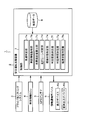
- FIG. 1 is a functional block diagram illustrating an embodiment.
- FIG. 2A is a diagram (No. 1) illustrating a determination range with respect to a driver's line-of-sight direction
- FIG. 2B is a diagram (part 2) illustrating a determination range with respect to the line-of-sight direction of the driver
- FIG. 3A is a diagram (No. 3) illustrating a determination range with respect to the driver's line-of-sight direction
- FIG. 3B is a diagram (part 4) illustrating a determination range with respect to the line-of-sight direction of the driver
- FIG. 4A is a diagram (No. 1) illustrating a determination range with respect to a driver's line-of-sight direction
- FIG. 2B is a diagram (part 2) illustrating a determination range with respect to the line-of-sight direction of the driver
- FIG. 3A is a diagram (No. 3) illustrating a determination range with respect to the driver's line-of-sight direction
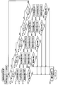
- FIG. 5 is a flowchart (part 1).
- FIG. 6 is a flowchart (part 2).
- FIG. 7 is a flowchart (part 3).
- FIG. 8 is a flowchart (part 4).
- the safe driving support system 1 includes a safe driving support device 2, a driver monitoring system 3, a vehicle information ECU (Electronic Control Unit) 4, a GPS (Global Positioning System) antenna 5, and an information notification device 6.
- a safe driving support device 2 includes a driver monitoring system 3, a vehicle information ECU (Electronic Control Unit) 4, a GPS (Global Positioning System) antenna 5, and an information notification device 6.
- vehicle information ECU Electronic Control Unit
- GPS Global Positioning System
- the driver monitoring system 3 has a driver photographing camera that photographs the upper body of the driver while the driver is sitting on the driver's seat.
- the driver monitoring system 3 outputs to the safe driving support device 2 a video signal including a video shot by the driver shooting camera.
- the driver photographing camera is a CCD (Charge Coupled Device) image sensor, a CMOS (Complementary Metal Oxide Semiconductor) image sensor, or the like, and may be singular or plural.
- the vehicle information ECU 4 is connected to various ECUs, various sensors, and the like via a vehicle-mounted network such as CAN (Controller Area Network), for example, so that data communication is possible.
- the vehicle information ECU 4 acquires the vehicle speed of the host vehicle, and outputs a vehicle speed signal indicating the acquired vehicle speed to the safe driving support device 2.
- the vehicle information ECU 4 acquires various types of information relating to vehicle travel as vehicle information, and outputs a vehicle information signal indicating the acquired vehicle information to the safe driving support device 2.
- the vehicle information includes, for example, the operation state of the blinker lever, the steering angle, the operation amount of the accelerator pedal, the operation amount of the brake pedal, and the like.
- the GPS antenna 5 captures GPS radio waves radiated from GPS satellites and outputs GPS signals to the safe driving support device 2.
- the information notification device 6 includes a display device 6a and an audio output device 6b.
- the display device 6a is, for example, a head-up display.
- the display device 6a displays warning display information that informs that the user is in a side-by-side state.
- the sound output device 6b is, for example, a speaker, and outputs sound information of a warning notifying that the user is in the side-by-side state when a sound output command signal is input from the safe driving support device 2.
- the safe driving support apparatus 2 includes a control unit 7 and a map data storage unit 8 that stores map data.
- the map data includes road data indicating the shape of the road, the number of lanes, and intersection data indicating the shape of the intersection.
- the map data storage unit 8 may be provided outside the safe driving support device 2.
- the control unit 7 includes a microcomputer having a CPU (Central Processing Unit), a ROM (Read Only Memory), a RAM (Random Access Memory), and an I / O (Input / Output).
- the control unit 7 executes processing corresponding to the computer program by executing the computer program stored in the non-transitional tangible recording medium, and controls the overall operation of the safe driving support device 2.
- the control unit 7 includes a vehicle speed determination unit 7a, a vehicle information acquisition unit 7b, a host vehicle position calculation unit 7c, a traveling scene determination unit 7d, a line-of-sight state determination unit 7e, a determination range determination unit 7f, and a determination time determination.
- Each of these units 7a to 7h is configured by a safe driving support program executed by the control unit 7, and is realized by software.
- the vehicle speed determination unit 7a determines the vehicle speed of the host vehicle using a vehicle speed signal input from the vehicle information ECU 4.
- the vehicle information acquisition part 7b acquires vehicle information using the vehicle information signal input from vehicle information ECU4.
- the own vehicle position calculation unit 7c uses the GPS signal input from the GPS antenna 5, calculates various parameters extracted from the GPS signal, and specifies the absolute position of the own vehicle by latitude and longitude.
- the own vehicle position calculation unit 7c reads the map data from the map data storage unit 8, compares the absolute position of the own vehicle with the map data, performs processing such as map matching, and calculates the own vehicle position.
- the traveling scene determination unit 7d determines the traveling scene of the host vehicle using the vehicle information and the host vehicle position. More specifically, the traveling scene determination unit 7d determines that the host vehicle is traveling on a straight road if, for example, the traveling position of the host vehicle is a straight road and the steering angle of the steering is a straight line. To do. For example, when the traveling position of the host vehicle is a curved road and the steering angle of the steering is an angle indicating a curve, the traveling scene determination unit 7d determines that the host vehicle is traveling on the curved road.
- the traveling scene determination unit 7d It is determined that the vehicle is turning right or left in the intersection.
- the line-of-sight state determination unit 7e determines the driver's line-of-sight state by using the video signal input from the driver monitoring system 3 and analyzing the movement of the driver's head and eyeballs.
- the line-of-sight state of the driver indicates the line-of-sight direction and time.
- the determination range determination unit 7f determines the determination range for the driver's line-of-sight direction using the determination result of the vehicle speed determination unit 7a and the determination result of the traveling scene determination unit 7d.
- the determination time determination unit 7g uses the determination result of the vehicle speed determination unit 7a and the determination result of the traveling scene determination unit 7d to determine the determination time for the time when the driver's line-of-sight direction is out of the determination range.
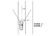
- the driver's line-of-sight direction is basically the front-rear direction of the host vehicle.
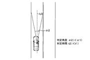
- the determination unit 7f determines the determination angle range centered on the reference line L0 in the front-rear direction of the host vehicle as the determination range. In this case, if the vehicle speed is relatively slow, the determination range determination unit 7f has a relatively wide field of view for the driver. Therefore, as illustrated in FIG. 2A, the determination range ⁇ 1 is determined to be relatively wide and the determination range is relatively wide. decide. On the other hand, if the vehicle speed is relatively high, the determination range determination unit 7f has a relatively narrow field of view of the driver. Therefore, as shown in FIG.
- the determination range ⁇ 2 is determined to be relatively narrow and the determination range is determined to be relatively narrow.
- the determination time determination unit 7g determines the determination time t1 to be relatively long because the change in the surrounding environment is relatively slow if the vehicle speed is relatively slow.
- the determination time determination unit 7g determines the determination time t2 to be relatively short because the change in the surrounding environment becomes relatively fast if the vehicle speed is relatively fast.
- the determination range determination unit 7f determines, for example, the determination angle ⁇ 1 as 50 [deg], the determination angle ⁇ 2 as 25 [deg], and the determination time t1 as 10 [s].
- Time t2 is determined to be 5 [s].
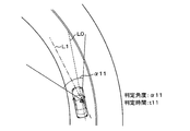
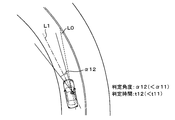
- the determination range determination unit 7f sets a center line L1 tilted to the left from the reference line L0 in the front-rear direction of the host vehicle. The range of the determination angle centered on the center line L1 is determined as the determination range.
- the determination range determination unit 7f determines the angle of inclination of the center line L1 from the reference line L0 using, for example, the steering angle of the steering and the shape of the road. Also in this case, the determination range determination unit 7f determines the determination angle ⁇ 11 to be relatively wide as shown in FIG. 3A because the driver's field of view is relatively wide when the vehicle speed is relatively slow. Decide widely. On the other hand, if the vehicle speed is relatively high, the determination range determination unit 7f has a relatively narrow field of view of the driver. Therefore, as illustrated in FIG. To do.
- the determination time determination unit 7g determines the determination time t11 to be relatively long because the change in the surrounding environment is relatively slow if the vehicle speed is relatively slow. On the other hand, the determination time determination unit 7g determines the determination time t12 to be relatively short because the change in the surrounding environment becomes relatively fast if the vehicle speed is relatively high. The same applies to the case where the host vehicle is driving on a right curve road.
- the determination range determination unit 7f also sets the center line L2 tilted to the left from the reference line L0 in the front-rear direction of the host vehicle.
- a determination angle range centered on the line L2 is determined as a determination range.
- the determination range determination unit 7f determines the angle of inclination of the center line L2 from the reference line L0 using, for example, the steering angle of the steering and the shape of the road.
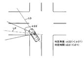
- the determination range determination unit 7f causes the host vehicle to travel on a curved road.
- the determination range is determined wider than the case where Also in this case, the determination range determination unit 7f determines the determination angle ⁇ 21 to be relatively wide as shown in FIG. 4A because the driver's field of view is relatively wide when the vehicle speed is relatively slow. Decide widely.
- the determination range determination unit 7f has a relatively narrow field of view for the driver. Therefore, as illustrated in FIG. 4B, the determination range ⁇ 22 is determined to be relatively narrow and the determination range is relatively wide. To do.
- the determination time determination unit 7g determines the determination time t21 to be relatively long because the change in the surrounding environment is relatively slow if the vehicle speed is relatively slow. On the other hand, the determination time determination unit 7g determines the determination time t22 to be relatively short because the change in the surrounding environment becomes relatively fast if the vehicle speed is relatively high. The same applies when the host vehicle makes a right turn inside the intersection.
- the look-ahead state determination unit 7h determines whether the driver is in the look-ahead state using the determination result of the line-of-sight state determination unit 7, the determination range and the determination time determined as described above. More specifically, the look-ahead state determination unit 7h determines whether or not the time during which the driver's line-of-sight direction is out of the determination range has continued for the determination time, and determines whether or not the driver is in the look-ahead state. When the look-ahead state determination unit 7h determines that the time during which the driver's line-of-sight direction is out of the determination range has continued for the determination time, the driver determines that the driver is in the look-aside state.
- the driver looks aside. It is determined that it is not in a state.
- the control unit 7 performs safe driving support processing.
- the control unit 7 starts the safe driving support process when a start condition of the safe driving support process is established, for example, the ignition switch is switched from OFF to ON.
- the control unit 7 may add that the driver has performed a predetermined operation to the start condition of the safe driving support process.
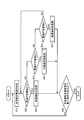
- the control unit 7 determines the vehicle speed of the host vehicle (S1, corresponding to a vehicle speed determination procedure).
- the control unit 7 classifies the vehicle speed of the host vehicle into a low speed range (for example, 0 to 30 km / h), a medium speed range (for example, 30 km / h to 80 km / h), and a high speed range (for example, 80 km / h). It is determined which vehicle speed the vehicle belongs to (S2 to S4).
- control unit 7 determines that the vehicle speed of the host vehicle is in the low speed range (S2: YES)
- the control unit 7 proceeds to a low speed range determination process (S5) and determines that the vehicle speed of the host vehicle is in the medium speed range (S3: (YES), the process proceeds to a medium speed range determination process (S6), and if it is determined that the vehicle speed of the host vehicle is a high speed range (S4: YES), the process proceeds to a high speed range determination process (S7).
- the control unit 7 determines the traveling scene of the own vehicle using the vehicle information and the own vehicle position (S11, corresponding to the traveling scene determination procedure).
- the control unit 7 divides the traveling scene of the host vehicle into a straight line, a left curve, a right curve, a left turn, and a right turn, and determines which section the traveling scene of the host vehicle is (S12 to S16). If the control unit 7 determines that the host vehicle is traveling on a straight road and the traveling scene is a straight line (S12: YES), the control unit 7 determines a determination range for the line-of-sight direction of the driver (S17, corresponding to a determination range determination procedure). The determination time for the time when the line-of-sight direction of the driver is out of the determination range is determined (S18, corresponding to the determination time determination procedure).
- the controller 7 uses the video signal input from the driver monitoring system 3 to determine the driver's line-of-sight state (S19, corresponding to the line-of-sight state determination procedure), and determines the driver's line-of-sight state, determination range, and determination time. Used to determine whether or not the driver is in a look-aside state (S20, corresponding to a look-ahead state determination procedure).
- control unit 7 determines that the time during which the driver's line-of-sight direction is out of the determination range has continued for the determination time and determines that the driver is in the side-by-side state (S20: YES)
- the control unit 7 displays the display command signal and the audio output command signal
- a warning is output from the information notification device 6 to be notified to the notification device 6 to indicate that it is a side-by-side state (S21), and the low speed region determination process is terminated.
- control unit 7 determines that the time during which the driver's line-of-sight direction is out of the determination range has not continued for the determination time and determines that the driver is not in the look-aside state (S20: NO), the control unit 7 notifies that the driver is in the look-aside state.
- the low speed region determination process is terminated without causing the information notification device 6 to notify the warning.
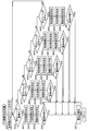
- the control unit 7 determines a determination range (S22, S26, S30, S34) and determines The time is determined (S23, S27, S31, S35), the line of sight of the driver is determined (S24, S28, S32, S36), and it is determined whether the driver is in the sideways state (S25, S29, S33, S37). That is, if the control unit 7 determines that the vehicle speed of the host vehicle is in the low speed range, the control unit 7 changes the determination range and the determination range according to the traveling scene, and determines whether or not the driver is in an aside state.
- the control unit 7 When the medium speed range determination process is started, the control unit 7 performs S41 to S67 similar to S11 to S37 described in the low speed range determination process described above.
- the control unit 7 When the high speed region determination process is started, the control unit 7 performs S71 to S97 similar to S11 to S37 described in the low speed region determination process and S41 to S67 described in the medium speed region determination process. That is, even when the control unit 7 determines that the vehicle speed of the host vehicle is in the middle speed range or the high speed range, the control unit 7 changes the determination range and the determination time according to the traveling scene, and determines whether or not the driver is in an aside state. judge.
- the control unit 7 determines whether or not the end condition of the safe driving support process is satisfied (S8), and the safe driving support If it is determined that the process termination condition is not satisfied (S8: NO), the process returns to step S1, and step S1 and subsequent steps are repeated. If it determines with the completion
- the determination range and the determination time are determined using the vehicle speed of the host vehicle and the traveling scene of the host vehicle, and the determination range and the determination time are used to determine whether or not the driver is in an aside state. I did it. Accordingly, it is possible to determine whether or not the driver is looking aside from various aspects using the vehicle speed of the own vehicle and the traveling scene of the own vehicle, and whether or not the driver is looking aside is determined with high accuracy. be able to.
- the safe driving support device 2 it is determined whether the traveling scene of the own vehicle is straight ahead, a curve, or a left / right turn. In this way, when the host vehicle is traveling on a straight road, when the host vehicle is traveling on a curved road, it is determined whether or not the driver is looking aside depending on whether the host vehicle turns right or left in the intersection. Can do.
- the vehicle speed of the host vehicle is determined in three categories of the low speed range, the medium speed range, and the high speed range is illustrated, a configuration in which the vehicle speed of the host vehicle is determined in two categories or four or more categories may be used.
Landscapes
- Physics & Mathematics (AREA)
- General Physics & Mathematics (AREA)
- Engineering & Computer Science (AREA)
- Mechanical Engineering (AREA)
- Traffic Control Systems (AREA)
- Fittings On The Vehicle Exterior For Carrying Loads, And Devices For Holding Or Mounting Articles (AREA)
Applications Claiming Priority (2)
| Application Number | Priority Date | Filing Date | Title |
|---|---|---|---|
| JP2016-107373 | 2016-05-30 | ||
| JP2016107373A JP6583144B2 (ja) | 2016-05-30 | 2016-05-30 | 安全運転支援装置及び安全運転支援プログラム |
Publications (1)
| Publication Number | Publication Date |
|---|---|
| WO2017208795A1 true WO2017208795A1 (ja) | 2017-12-07 |
Family
ID=60477446
Family Applications (1)
| Application Number | Title | Priority Date | Filing Date |
|---|---|---|---|
| PCT/JP2017/018191 Ceased WO2017208795A1 (ja) | 2016-05-30 | 2017-05-15 | 安全運転支援装置及び安全運転支援プログラム |
Country Status (2)
| Country | Link |
|---|---|
| JP (1) | JP6583144B2 (OSRAM) |
| WO (1) | WO2017208795A1 (OSRAM) |
Cited By (1)
| Publication number | Priority date | Publication date | Assignee | Title |
|---|---|---|---|---|
| CN116645787A (zh) * | 2023-05-04 | 2023-08-25 | 浙江极氪智能科技有限公司 | 用于辅助安全驾驶的ar设备及辅助安全驾驶的方法 |
Families Citing this family (3)
| Publication number | Priority date | Publication date | Assignee | Title |
|---|---|---|---|---|
| JP7309480B2 (ja) * | 2019-06-27 | 2023-07-18 | フォルシアクラリオン・エレクトロニクス株式会社 | 車載装置、及び車載装置の制御方法 |
| JP2022088892A (ja) * | 2020-12-03 | 2022-06-15 | ダイハツ工業株式会社 | 脇見検出システム |
| JP7711688B2 (ja) | 2022-12-05 | 2025-07-23 | トヨタ自動車株式会社 | 情報処理装置、車両、情報処理システム、情報処理方法およびプログラム |
Citations (5)
| Publication number | Priority date | Publication date | Assignee | Title |
|---|---|---|---|---|
| JP2008174092A (ja) * | 2007-01-18 | 2008-07-31 | Aisin Seiki Co Ltd | 速度制御装置 |
| JP2010066968A (ja) * | 2008-09-10 | 2010-03-25 | Toyota Motor Corp | 視線状態検出装置 |
| JP2010257293A (ja) * | 2009-04-27 | 2010-11-11 | Toyota Motor Corp | ドライバ状態監視装置及び車両制御装置 |
| JP2012022504A (ja) * | 2010-07-14 | 2012-02-02 | Honda Motor Co Ltd | 脇見判定装置 |
| JP2012058769A (ja) * | 2010-09-03 | 2012-03-22 | Honda Motor Co Ltd | 脇見判定装置 |
-
2016
- 2016-05-30 JP JP2016107373A patent/JP6583144B2/ja not_active Expired - Fee Related
-
2017
- 2017-05-15 WO PCT/JP2017/018191 patent/WO2017208795A1/ja not_active Ceased
Patent Citations (5)
| Publication number | Priority date | Publication date | Assignee | Title |
|---|---|---|---|---|
| JP2008174092A (ja) * | 2007-01-18 | 2008-07-31 | Aisin Seiki Co Ltd | 速度制御装置 |
| JP2010066968A (ja) * | 2008-09-10 | 2010-03-25 | Toyota Motor Corp | 視線状態検出装置 |
| JP2010257293A (ja) * | 2009-04-27 | 2010-11-11 | Toyota Motor Corp | ドライバ状態監視装置及び車両制御装置 |
| JP2012022504A (ja) * | 2010-07-14 | 2012-02-02 | Honda Motor Co Ltd | 脇見判定装置 |
| JP2012058769A (ja) * | 2010-09-03 | 2012-03-22 | Honda Motor Co Ltd | 脇見判定装置 |
Cited By (1)
| Publication number | Priority date | Publication date | Assignee | Title |
|---|---|---|---|---|
| CN116645787A (zh) * | 2023-05-04 | 2023-08-25 | 浙江极氪智能科技有限公司 | 用于辅助安全驾驶的ar设备及辅助安全驾驶的方法 |
Also Published As
| Publication number | Publication date |
|---|---|
| JP2017215654A (ja) | 2017-12-07 |
| JP6583144B2 (ja) | 2019-10-02 |
Similar Documents
| Publication | Publication Date | Title |
|---|---|---|
| EP3357793B1 (en) | Parking assist apparatus | |
| US10870435B2 (en) | Notice management apparatus and notice management method | |
| CA3069114C (en) | Parking assistance method and parking assistance device | |
| US20190143993A1 (en) | Distracted driving determination apparatus, distracted driving determination method, and program | |
| US20180253106A1 (en) | Periphery monitoring device | |
| US20200017123A1 (en) | Drive mode switch controller, method, and program | |
| JP2016021653A (ja) | 周辺監視装置、及びプログラム | |
| US10843726B2 (en) | Method and apparatus for assisting steering of vehicle | |
| JP6583144B2 (ja) | 安全運転支援装置及び安全運転支援プログラム | |
| US20200285865A1 (en) | Information providing apparatus for vehicle, information providing method for vehicle, and computer-readable recording medium | |
| WO2018150642A1 (ja) | 周辺監視装置 | |
| JP2005199814A (ja) | 車載アプリケーション選択システム及び車載アプリケーション選択装置 | |
| JP2018188063A (ja) | 運転支援装置および運転支援方法 | |
| CN115071721B (zh) | 预测性驾驶员警觉性评估 | |
| JP6130118B2 (ja) | 画像処理システム、画像処理装置、画像処理方法、及び、プログラム | |
| JP2013109505A (ja) | 周辺監視装置 | |
| EP1555159B1 (en) | Vehicle situation monitoring apparatus and vehicle situation monitoring method | |
| JP6582392B2 (ja) | 車載周辺物体報知システム、物体報知システム、報知制御装置 | |
| WO2017204016A1 (ja) | 安全運転支援装置及び安全運転支援プログラム | |
| JP4622544B2 (ja) | 車両の運転支援装置 | |
| US20200342761A1 (en) | Notification apparatus and in-vehicle device | |
| JP2010069922A (ja) | 車線認識装置 | |
| JP5040851B2 (ja) | 脇見運転判定装置 | |
| JP4815960B2 (ja) | 視認状態判断装置、自動車、及び視認状態判断方法 | |
| JP2017220171A (ja) | 安全運転支援装置及び安全運転支援プログラム |
Legal Events
| Date | Code | Title | Description |
|---|---|---|---|
| 121 | Ep: the epo has been informed by wipo that ep was designated in this application |
Ref document number: 17806353 Country of ref document: EP Kind code of ref document: A1 |
|
| NENP | Non-entry into the national phase |
Ref country code: DE |
|
| 122 | Ep: pct application non-entry in european phase |
Ref document number: 17806353 Country of ref document: EP Kind code of ref document: A1 |