WO2017208778A1 - 流体バルブおよびその製造方法 - Google Patents
流体バルブおよびその製造方法 Download PDFInfo
- Publication number
- WO2017208778A1 WO2017208778A1 PCT/JP2017/017972 JP2017017972W WO2017208778A1 WO 2017208778 A1 WO2017208778 A1 WO 2017208778A1 JP 2017017972 W JP2017017972 W JP 2017017972W WO 2017208778 A1 WO2017208778 A1 WO 2017208778A1
- Authority
- WO
- WIPO (PCT)
- Prior art keywords
- valve body
- sliding coating
- sliding
- valve
- coating
- Prior art date
- Legal status (The legal status is an assumption and is not a legal conclusion. Google has not performed a legal analysis and makes no representation as to the accuracy of the status listed.)
- Ceased
Links
Images





Classifications
-
- F—MECHANICAL ENGINEERING; LIGHTING; HEATING; WEAPONS; BLASTING
- F16—ENGINEERING ELEMENTS AND UNITS; GENERAL MEASURES FOR PRODUCING AND MAINTAINING EFFECTIVE FUNCTIONING OF MACHINES OR INSTALLATIONS; THERMAL INSULATION IN GENERAL
- F16J—PISTONS; CYLINDERS; SEALINGS
- F16J15/00—Sealings
- F16J15/16—Sealings between relatively-moving surfaces
- F16J15/18—Sealings between relatively-moving surfaces with stuffing-boxes for elastic or plastic packings
-
- F—MECHANICAL ENGINEERING; LIGHTING; HEATING; WEAPONS; BLASTING
- F16—ENGINEERING ELEMENTS AND UNITS; GENERAL MEASURES FOR PRODUCING AND MAINTAINING EFFECTIVE FUNCTIONING OF MACHINES OR INSTALLATIONS; THERMAL INSULATION IN GENERAL
- F16K—VALVES; TAPS; COCKS; ACTUATING-FLOATS; DEVICES FOR VENTING OR AERATING
- F16K5/00—Plug valves; Taps or cocks comprising only cut-off apparatus having at least one of the sealing faces shaped as a more or less complete surface of a solid of revolution, the opening and closing movement being predominantly rotary
- F16K5/02—Plug valves; Taps or cocks comprising only cut-off apparatus having at least one of the sealing faces shaped as a more or less complete surface of a solid of revolution, the opening and closing movement being predominantly rotary with plugs having conical surfaces; Packings therefor
-
- F—MECHANICAL ENGINEERING; LIGHTING; HEATING; WEAPONS; BLASTING
- F16—ENGINEERING ELEMENTS AND UNITS; GENERAL MEASURES FOR PRODUCING AND MAINTAINING EFFECTIVE FUNCTIONING OF MACHINES OR INSTALLATIONS; THERMAL INSULATION IN GENERAL
- F16K—VALVES; TAPS; COCKS; ACTUATING-FLOATS; DEVICES FOR VENTING OR AERATING
- F16K5/00—Plug valves; Taps or cocks comprising only cut-off apparatus having at least one of the sealing faces shaped as a more or less complete surface of a solid of revolution, the opening and closing movement being predominantly rotary
- F16K5/04—Plug valves; Taps or cocks comprising only cut-off apparatus having at least one of the sealing faces shaped as a more or less complete surface of a solid of revolution, the opening and closing movement being predominantly rotary with plugs having cylindrical surfaces; Packings therefor
-
- F—MECHANICAL ENGINEERING; LIGHTING; HEATING; WEAPONS; BLASTING
- F16—ENGINEERING ELEMENTS AND UNITS; GENERAL MEASURES FOR PRODUCING AND MAINTAINING EFFECTIVE FUNCTIONING OF MACHINES OR INSTALLATIONS; THERMAL INSULATION IN GENERAL
- F16K—VALVES; TAPS; COCKS; ACTUATING-FLOATS; DEVICES FOR VENTING OR AERATING
- F16K5/00—Plug valves; Taps or cocks comprising only cut-off apparatus having at least one of the sealing faces shaped as a more or less complete surface of a solid of revolution, the opening and closing movement being predominantly rotary
- F16K5/06—Plug valves; Taps or cocks comprising only cut-off apparatus having at least one of the sealing faces shaped as a more or less complete surface of a solid of revolution, the opening and closing movement being predominantly rotary with plugs having spherical surfaces; Packings therefor
Definitions
- the present disclosure relates to a fluid valve used for a fluid flow path and a method for manufacturing the fluid valve.
- Patent Document 1 describes a flow path switching valve including a valve body, a valve body, and a seal member.
- the seal member is formed in a cylindrical shape with an elastic material, and is accommodated in the valve chamber of the valve body.
- the valve body is accommodated inside the seal member in the valve chamber of the valve body.
- valve body When the valve body is driven to rotate, the valve body rotates and slides on the inner peripheral surface of the seal member, and the flow path is opened or closed or switched.
- the seal member Since the inner diameter of the seal member is slightly smaller than the outer diameter of the valve body, the seal member is stretched by the valve body to generate an elastic force, and the seal member comes into close contact with the valve body to exert the sealing force.
- the seal member is integrally formed in a cylindrical shape, the number of parts of the seal member can be reduced as compared with the case where the seal member is divided into a plurality of plate-like members.
- the present inventor studied to apply a fluororesin sliding film on the inner peripheral surface of the sealing member in order to improve the sliding between the valve body and the sealing member.
- the present inventor also examined a proposal to mold the valve body itself with a fluororesin.
- fluororesin is difficult to mold with a mold, it is manufactured by cutting out from a fluororesin rod or lump. It is necessary to do, and productivity is bad and is not realistic.
- This indication aims at improving the slidability of a valve body and a sealing member in view of the above-mentioned point.
- a main body having at least one opening, and a valve body that adjusts the opening of the at least one opening by rotating inside the main body.
- a seal member that is elastically deformed between the main body and the valve body, and a sliding coating that is provided on the outer surface of the valve body and rotates with the valve body and slides on the seal member.
- the sliding coating is provided on the outer surface of the valve body, it is avoided that the elasticity of the sealing member is hindered by the sliding coating as in the case where the sliding coating is provided on the sealing member. it can. Also, the sliding coating can be easily provided as compared with the case where the sliding coating is provided on the seal member. Therefore, the slidability between the valve body and the seal member can be improved.
- a coating formed in a tubular shape with a heat-shrinkable material is used as the sliding coating, and the sliding coating is formed outside the valve body.
- a heating step is included in which heat is applied to the sliding coating to bring the sliding coating into close contact with the outer peripheral surface of the valve body.
- the fluid valve manufacturing method of the third aspect of the present disclosure includes an insert molding step of insert molding the valve body and the sliding coating.
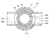
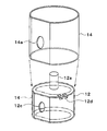
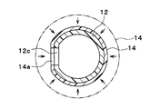
- FIG. 2 is a sectional view taken along the line II-II in FIG. It is a perspective view of the valve body and seal member in a 1st embodiment. It is explanatory drawing explaining the assembly
- a fluid valve 10 shown in FIGS. 1 and 2 is a valve for switching the flow of fluid.
- the fluid valve 10 is, for example, a valve that switches the flow of cooling water that flows out from the engine of the vehicle.
- the fluid valve 10 has a valve body 11.
- the valve body 11 is a housing that forms the main body of the fluid valve 10 and is formed of resin.
- the valve body 11 is formed with first to third ports 11a to 11c.
- the first to third ports 11a to 11c form an inflow port through which fluid flows or an outflow port from which fluid flows out.
- the first to third ports 11a to 11c are pipe connection portions to which fluid pipes (not shown) are connected.
- the first port 11 a is formed on the bottom surface of the valve body 11.
- the second port 11 b and the third port 11 c are formed on the side surface portion of the valve body 11.
- the fluid valve 10 has a valve body 12, a packing 13 and a sliding coating 14 shown in FIG.
- the valve body 12 rotates in the internal space of the valve body 11, the opening degree of the second port 11b and the third port 11c is adjusted.
- the valve body 12 is formed in a substantially cylindrical shape with resin.
- the valve body 12 is provided with a drive shaft 12a connected to an actuator side (not shown).
- the valve body 12 is rotationally driven by an actuator (not shown).
- the outer peripheral surface of the valve body 12 is opposed to the second port 11b and the third port 11c with a predetermined gap.
- a communication port 12 c is formed on the outer peripheral surface of the valve body 12.
- a packing 13 is disposed between the outer peripheral surface of the valve body 12 and the inner peripheral surface of the valve body 11.
- the packing 13 is a seal member that prevents leakage of cooling water between the outer peripheral surface of the valve body 12 and the inner peripheral surface of the valve body 11.
- the packing 13 is formed in a cylindrical shape with an elastic material such as rubber, and is elastically deformed between the valve body 11 and the valve body 12. In the packing 13, openings 13 b and 13 c that overlap with the second port 11 b and the third port 11 c of the valve body 11 are formed.
- a sliding coating 14 is provided on the outer peripheral surface of the valve body 12.
- the sliding coating 14 is a sliding member that ensures slidability between the outer peripheral surface of the valve body 12 and the inner peripheral surface of the packing 13.
- the sliding coating 14 is made of a fluorine resin.
- fluororesin include PTFE (tetrafluorinated resin), PFA (perfluoroalkoxy fluororesin), FEP (tetrafluoroethylene / hexafluoropropylene copolymer), ETFE (ethylene / tetrafluoroethylene copolymer). Etc.
- the sliding coating 14 has a substantially cylindrical film shape, and is in close contact with the outer peripheral surface of the valve body 12 by heat shrinkage.
- the sliding coating 14 is continuously connected in the circumferential direction of the valve body 12 (in other words, the rotational direction of the valve body 12). That is, the sliding coating 14 is not divided into a plurality of pieces in the circumferential direction of the valve body 12.
- a communication hole 14 a that is superposed on the communication port 12 c of the valve body 12 is formed.
- the portion of the outer peripheral surface of the valve body 12 where the communication port 12c is formed has a flat shape. Therefore, the communication port 12 c of the valve body 12 and the communication hole 14 a of the sliding coating 14 are separated from the inner peripheral surface of the cylindrical packing 13. Thereby, when the valve body 12 rotates, it can suppress that the peripheral part of the communicating hole 14a of the sliding coating 14 is caught in the packing 13, or is turned up from the valve body 12.
- the sliding coating 14 a coating formed into a cylindrical shape with a heat-shrinkable material (specifically, a fluorine-based resin that thermally shrinks) is used. As shown in FIG. 4, the inner circumferential length of the sliding coating 14 at this time is larger than the outer circumferential length of the valve body 12, and the axial length of the sliding coating 14 at this time is the valve body 12. Among these, the dimension is larger than the axial length of the portion sliding with the packing 13.
- a heat-shrinkable material specifically, a fluorine-based resin that thermally shrinks
- the sliding coating 14 is placed on the outside of the valve body 12 to apply heat. As a result, the sliding coating 14 is thermally contracted.
- the two-dot chain line in FIG. 5 indicates the shape of the sliding coating 14 before thermal contraction.
- the sliding coating 14 adheres to the outer peripheral surface of the valve body 12 by the thermal contraction of the sliding coating 14.
- the sliding coating 14 after the heat shrinkage extends to the upper surface and the lower surface of the valve body 12. That is, the sliding coating 14 is in close contact with not only the outer peripheral surface of the valve body 12 but also the upper and lower surfaces of the valve body 12. Thereby, the sliding coating 14 and the valve body 12 are engaged with each other in the axial direction of the valve body 12, and the sliding coating 14 is prevented from being displaced in the axial direction of the valve body 12.
- a recess 12 d is formed on the outer peripheral surface of the valve body 12.
- the sliding coating 14 is thermally contracted and enters and closes into the recess 12 d of the valve body 12, the sliding coating 14 and the valve body 12 are engaged with each other in the circumferential direction. Prevents deviation in the circumferential direction.
- the communication port 12 c is illustrated in the single-state valve body 12, and the communication hole 14 a is illustrated in the single-state sliding coating 14. After the contact with the body 12, the communication hole 14a of the sliding coating 14 and the communication port 12c of the valve body 12 may be simultaneously drilled in the hole machining step.
- the sliding coating 14 is provided on the outer peripheral surface of the valve body 12, the sliding resistance between the outer peripheral surface of the valve body 12 and the inner peripheral surface of the packing 13 can be reduced when the valve body 12 is rotationally driven. .
- a low-load low-torque motor can be employed as a drive mechanism (specifically, an actuator, a gear, etc.) that rotationally drives the valve body 12, so that the drive mechanism that rotationally drives the valve body 12 can be downsized.
- the fluid valve 10 can be reduced in size, weight and power saving, and the level of vibration and noise can be reduced.
- the sliding coating 14 is provided on the outer surface of the valve body 12 and rotates with the valve body 12 to slide with the packing 13.
- the sliding coating 14 is provided on the outer surface of the valve body 12, the elasticity of the packing 13 is hindered by the sliding coating 14 as in the case where the sliding coating 14 is provided on the packing 13. Can be avoided. Further, the sliding coating 14 can be easily provided as compared with the case where the sliding coating 14 is provided on the inner peripheral surface of the cylindrical packing 13. Therefore, the slidability between the valve body 12 and the packing 13 can be improved.
- valve body 12 and the sliding coating 14 are engaged with each other in at least one of the axial direction of the valve body 12 and the rotation direction of the valve body 12. Thereby, it can suppress that the sliding coating 14 shifts
- the sliding coating 14 has a shape continuously connected in the circumferential direction of the valve body 12. According to this, since the joint of the sliding coating 14 is not formed in the circumferential direction of the valve body 12, the sliding coating 14 is prevented from being caught by the packing 13 or being turned up from the valve body 12 when the valve body 12 rotates. it can.
- a coating formed in a cylindrical shape with a heat-shrinkable material is used as the sliding coating 14, and the sliding coating 14 is put on the outside of the valve body 12, and then the sliding coating is applied.
- 14 includes a heating step in which heat is applied to 14 to bring the sliding coating 14 into close contact with the outer peripheral surface of the valve body 12. Thereby, the sliding coating 14 can be easily provided on the outer surface of the valve body 12.
- the manufacturing method of the fluid valve 10 of the present embodiment includes a hole machining step of simultaneously machining the hole shape in the sliding coating 14 and the valve body 12 after the heating step. Thereby, the communication hole 14a of the sliding coating 14 and the communication port 12c of the valve body 12 can be formed with high accuracy.
- the sliding coating 14 is in close contact with the outer peripheral surface of the valve body 12 by heat shrinkage.
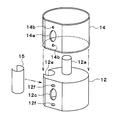
- the sliding coating 14 is a spring member. 15 is fixed to the outer peripheral surface of the valve body 12.
- a groove 12 e is formed on the outer peripheral surface of the valve body 12.
- the groove part 12e is formed over the whole area of the outer peripheral surface of the valve body 12 in the axial direction.
- the sliding coating 14 enters the groove 12e of the valve body 12.
- the sliding coating 14 is sandwiched between the groove 12 e of the valve body 12 and the spring member 15.
- the spring member 15 is an elastic member that is elastically deformed.
- the spring member 15 has a cylindrical shape having a notch.
- the sliding coating 14 is fixed to the outer peripheral surface of the valve body 12 by the spring member 15 spreading in the groove 12e by its own elastic force.
- a positioning pin 12 f is formed on the outer peripheral surface of the valve body 12.
- a positioning hole 14 b is formed in the sliding coating 14.
- the positioning pin 12 f of the valve body 12 is inserted into the positioning hole 14 b of the sliding coating 14.
- the spring member 15 is fitted into the groove 12 e from the outside of the valve body 12 and the sliding coating 14.
- the sliding coating 14 comes into close contact with the outer peripheral surface of the valve body 12.
- a two-dot chain line in FIG. 7 indicates the shape of the sliding coating 14 before the spring member 15 is fitted. Since the sliding member 14 is drawn into the groove 12e by fitting the spring member 15 into the groove 12e, the sliding member 14 comes into close contact with the outer peripheral surface of the valve body 12.
- the drilling of the communication hole 14 a of the sliding coating 14 and the communication port 12 c of the valve body 12 may be performed before the sliding coating 14 is fixed to the valve body 12, or the sliding coating 14 is attached to the valve body 12. It may be performed after fixing.
- a groove 12e into which the sliding coating 14 enters is formed on the outer surface of the valve body 12, and the spring member 15 is fitted into the groove 12e from the outside of the sliding coating 14.
- the sliding coating 14 is fixed to the groove 12e.
- Insert molding is a method of integrating resin and insert parts by inserting an insert part into a mold, closing the mold, and pouring resin.
- the procedure for insert-molding the sliding coating 14 and the valve body 12 will be described with reference to FIG.
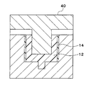
- the sliding coating 14 formed in a cylindrical shape is set in the mold 20.
- the insert molding step the sliding coating 14 and the valve body 12 are insert-molded by filling the mold 20 with a molten resin.
- the take-out step the insert-formed sliding coating 14 and the valve body 12 are taken out from the mold 20.
- the positioning pin 12f may be formed on the outer peripheral surface of the valve body 12, and the positioning hole 14b may be formed in the sliding coating 14.
- the manufacturing method of the fluid valve 10 of the present embodiment includes an insert molding process in which the valve body 12 and the sliding coating 14 are insert-molded. Also in this embodiment, the sliding coating 14 can be provided on the outer surface of the valve body 12 as in the above embodiment.
- valve body 12 and the sliding coating 14 are formed in a cylindrical shape, but the shapes of the valve body 12 and the sliding coating 14 are not limited thereto.
- valve body 12 and the packing 13 may be formed in a cylindrical shape having a frustoconical outer shape.
- the valve body 12 and the packing 13 may be formed in a cylindrical shape having a spherical outer shape.
- valve body 12 only needs to have a circular outer shape when cut in a direction perpendicular to the drive shaft 12a, and the packing 13 is cut in a direction perpendicular to the drive shaft 12a. It is sufficient that the inner shape of the cross section at the time is circular.
- the first to third ports 11a to 11c are formed in the valve body 11.
- the present invention is not limited to this, and the number and arrangement of the ports of the valve body 11 can be changed as appropriate. .
- the communication port 12c is formed on the outer peripheral surface of the valve body 12, but the number of the communication ports 12c can be appropriately changed.
Landscapes
- Engineering & Computer Science (AREA)
- General Engineering & Computer Science (AREA)
- Mechanical Engineering (AREA)
- Taps Or Cocks (AREA)
- Sealing Devices (AREA)
Abstract
流体バルブは、少なくとも1つの開口部(11b、11c)を有する本体(11)と、本体(11)の内部で回転することによって前記少なくとも1つの開口部(11b、11c)の開度を調節する弁体(12)と、本体(11)と弁体(12)との間で弾性変形するシール部材(13)と、弁体(12)の外表面に設けられ、弁体(12)とともに回転してシール部材(13)と摺動する摺動被膜(14)とを備える。前記流体バルブの製造方法は、摺動被膜(14)として、熱収縮材料で筒状に成形された被膜を用い、弁体(12)の外側に摺動被膜(14)を被せた後、摺動被膜(14)に熱を加えて摺動被膜(14)を弁体(12)の外周面に密着させる加熱工程を含む。前記流体バルブの製造方法は、弁体(12)および摺動被膜(14)をインサート成形するインサート成形工程を含む。
Description
本出願は、2016年6月2日に出願された日本特許出願番号2016-110988号に基づくもので、ここにその記載内容を援用する。
本開示は、流体の流路に用いられる流体バルブ、およびその製造方法に関する。
従来、特許文献1には、弁本体と弁体とシール部材とを備える流路切替弁が記載されている。シール部材は、弾性材料にて円筒状に形成されており、弁本体の弁室に収容されている。弁体は、弁本体の弁室においてシール部材の内側に収容されている。
そして、弁体が回転駆動されると、弁体がシール部材の内周面を回転摺動して流路の開閉または切り替えが行われる。
シール部材の内径は弁体の外径よりも若干小さくなっているので、シール部材が弁体によって伸ばされて弾性力が発生し、シール部材が弁体に密着してシール力を発揮する。
この従来技術では、シール部材が円筒状に一体成形されているので、シール部材が複数個の板状部材に分割して成形されている場合と比較してシール部材の部品点数を削減できる。
上記従来技術では、シール部材が弁体に密着してシール力を発揮するので、弁体とシール部材との間で摺動抵抗が大きくなる。そのため、弁体を駆動するモータのトルクを大きくする必要があり、モータの大型化やモータの重量増加、モータの消費動力の増大を招いてしまう。
そこで、本発明者は、弁体とシール部材との摺動を良くするために、シール部材の内周面にフッ素系樹脂の摺動被膜を貼り付けることを検討した。
しかしながら、シール部材にフッ素系樹脂の摺動被膜が貼り付けられると、シール部材の弾性が摺動被膜によって阻害されてしまうので、安定したシール力を発揮できなくなる。
また、摺動被膜をシール部材に貼り付ける際に摺動被膜をシール部材に押圧する作業が必要となるので、シール部材の内周面に摺動被膜を貼り付けることが非常に困難である。すなわち、シール部材が複数個の板状部材に分割して成形されている場合、摺動被膜を板状のシール部材に押圧しやすいのに対し、上記従来技術のようにシール部材が円筒状に形成されている場合、摺動被膜を円筒状のシール部材の内周面に押圧するのが非常に困難である。
そこで、本発明者は、弁体自体をフッ素系樹脂で成形する案も検討したが、フッ素系樹脂は型による成形が困難であるので、フッ素系樹脂の棒材または塊材から削り出して製作する必要があり、生産性が悪く現実的ではない。
本開示は上記点に鑑みて、弁体とシール部材との摺動性を向上させることを目的とする。
上記目的を達成するため、本開示の第一の態様の流体バルブでは、少なくとも1つの開口部を有する本体と、本体の内部で回転することによって少なくとも1つの開口部の開度を調節する弁体と、本体と弁体との間で弾性変形するシール部材と、弁体の外表面に設けられ、弁体とともに回転してシール部材と摺動する摺動被膜とを備える。
これによると、摺動被膜が弁体の外表面に設けられているので、摺動被膜がシール部材に設けられている場合のようにシール部材の弾性が摺動被膜によって阻害されることを回避できる。また、シール部材に摺動被膜を設ける場合と比較して、摺動被膜を容易に設けることができる。したがって、弁体とシール部材との摺動性を向上できる。
上記目的を達成するため、本開示の第二の態様の流体バルブの製造方法では、摺動被膜として、熱収縮材料で筒状に成形された被膜を用い、弁体の外側に摺動被膜を被せた後、摺動被膜に熱を加えて摺動被膜を弁体の外周面に密着させる加熱工程を含む。
これにより、摺動被膜を弁体の外表面に良好に設けることができるので、弁体とシール部材との摺動性を向上できる。
上記目的を達成するため、本開示の第三の態様の流体バルブの製造方法では、弁体および摺動被膜をインサート成形するインサート成形工程を含む。
これにより、第二の態様の流体バルブの製造方法と同様の作用効果を得ることができる。
本開示についての上記目的およびその他の目的、特徴や利点は、添付の図面を参照しながら下記の詳細な記述により、より明確になる。その図面は、
第1実施形態における流体バルブを示す断面図である。
図1のII-II断面図である。
第1実施形態における弁体およびシール部材の斜視図である。
第1実施形態における弁体および摺動被膜の組付工程を説明する説明図である。
第1実施形態における摺動被膜の熱収縮工程を説明する説明図である。
第2実施形態における弁体および摺動被膜の組付工程を説明する説明図である。
第2実施形態における弁体および摺動被膜の組付工程を説明する説明図である。
第3実施形態における弁体および摺動被膜のインサート成形工程を説明する説明図である。
他の実施形態の第1実施例における弁体およびシール部材の斜視図である。
他の実施形態の第2実施例における弁体およびシール部材の斜視図である。
以下、実施形態について図に基づいて説明する。以下の各実施形態相互において、互いに同一もしくは均等である部分には、図中、同一符号を付してある。
(第1実施形態)
図1および図2に示す流体バルブ10は、流体の流れを切り替えるバルブである。流体バルブ10は、例えば、車両のエンジンから流出する冷却水の流れを切り替えるバルブである。
図1および図2に示す流体バルブ10は、流体の流れを切り替えるバルブである。流体バルブ10は、例えば、車両のエンジンから流出する冷却水の流れを切り替えるバルブである。
次に、流体バルブ10の構造について述べる。流体バルブ10はバルブボディ11を有している。バルブボディ11は、流体バルブ10の本体をなすハウジングであり、樹脂で形成されている。バルブボディ11には第1~3ポート11a~11cが形成されている。第1~3ポート11a~11cは、流体が流入する流入口、または流体が流出する流出口を形成している。第1~3ポート11a~11cは、図示しない流体配管が接続される配管接続部である。
第1ポート11aは、バルブボディ11の底面部に形成されている。第2ポート11bおよび第3ポート11cは、バルブボディ11の側面部に形成されている。
流体バルブ10は、図3に示す弁体12、パッキン13および摺動被膜14を有している。バルブボディ11の内部空間において弁体12が回転することによって第2ポート11bおよび第3ポート11cの開度を調節する。
弁体12は、樹脂にて略円筒状に形成されている。弁体12には、図示しないアクチュエータ側に接続される駆動シャフト12aが設けられている。弁体12は、図示しないアクチュエータによって回転駆動される。
弁体12の外周面は、第2ポート11bおよび第3ポート11cと所定の隙間を有して対向している。弁体12の外周面には連通口12cが形成されている。
弁体12の外周面とバルブボディ11の内周面との間には、パッキン13が配置されている。パッキン13は、弁体12の外周面とバルブボディ11の内周面との間に冷却水が漏れ出ることを防止するシール部材である。
パッキン13は、ゴム等の弾性材料で円筒状に形成されており、バルブボディ11と弁体12との間で弾性変形する。パッキン13には、バルブボディ11の第2ポート11bおよび第3ポート11cと重合する開口部13b、13cが形成されている。
弁体12の外周面には、摺動被膜14が設けられている。摺動被膜14は、弁体12の外周面とパッキン13の内周面との間で摺動性を確保する摺動部材である。
摺動被膜14は、フッ素系樹脂で形成されている。フッ素系樹脂は、例えばPTFE(四フッ素化樹脂)、PFA(ペルフルオロアルコキシフッ素樹脂)、FEP(四フッ化エチレン・六フッ化プロピレン共重合体)、ETFE(エチレン・四フッ化エチレン共重合体)等である。
摺動被膜14は、略円筒膜状の形状を有しており、弁体12の外周面に熱収縮によって密着している。摺動被膜14は、弁体12の周方向(換言すれば、弁体12の回転方向)に連続して繋がっている。すなわち、摺動被膜14は、弁体12の周方向に複数個に分割されていない。摺動被膜14には、弁体12の連通口12cに重合する連通孔14aが形成されている。
弁体12の外周面のうち連通口12cが形成されている部位は平坦な形状になっている。したがって、弁体12の連通口12cおよび摺動被膜14の連通孔14aは、円筒状のパッキン13の内周面に対して離間している。これにより、弁体12が回転した際に摺動被膜14のうち連通孔14aの周縁部がパッキン13に引っ掛かったり弁体12からめくれ上がったりすることを抑制できる。
次に、摺動被膜14を弁体12の外周面に熱収縮によって密着させる手順を図4および図5に基づいて説明する。
まず、摺動被膜14として、熱収縮材料(具体的には、熱収縮するフッ素系樹脂)で円筒状に成形された被膜を用いる。図4に示すように、このときの摺動被膜14の内周長は、弁体12の外周長よりも大きくなっており、このときの摺動被膜14の軸方向長さは、弁体12のうちパッキン13と摺動する部位の軸方向長さよりも大きい寸法になっている。
次いで、加熱工程において、摺動被膜14を弁体12の外側に被せて熱を加える。これにより、摺動被膜14が熱収縮する。図5の二点鎖線は、熱収縮前の摺動被膜14の形状を示している。摺動被膜14が熱収縮することによって、摺動被膜14が弁体12の外周面に密着する。
図4の二点鎖線は、熱収縮後の摺動被膜14の形状を示している。熱収縮後の摺動被膜14は、弁体12の上面および下面まで回り込んでいる。すなわち、摺動被膜14は、弁体12の外周面のみならず弁体12の上面および下面にも密着している。これにより、摺動被膜14と弁体12とが弁体12の軸方向に互いに係合し、摺動被膜14が弁体12の軸方向にずれることを防止している。
図4に示すように、弁体12の外周面には凹部12dが形成されている。摺動被膜14が熱収縮して弁体12の凹部12dに入り込んで密着することによって、摺動被膜14と弁体12とが周方向に互いに係合し、摺動被膜14が弁体12の周方向にずれることを防止している。
図4では、理解を容易にするために、単体状態の弁体12に連通口12cを図示し、単体状態の摺動被膜14に連通孔14aを図示しているが、摺動被膜14を弁体12に密着させた後、孔加工工程において、摺動被膜14の連通孔14aおよび弁体12の連通口12cを同時に孔明け加工してもよい。
次に、上記構成における作用効果を説明する。弁体12の外周面に摺動被膜14が設けられているので、弁体12を回転駆動する際に弁体12の外周面とパッキン13の内周面との間の摺動抵抗を低減できる。
そのため、弁体12を回転駆動する駆動機構(具体的にはアクチュエータやギヤ等)として低負荷の低トルクモータを採用できるので、弁体12を回転駆動する駆動機構を小型化できる。その結果、流体バルブ10の小型化、軽量化および省動力化を実現できるとともに、振動や騒音のレベルを低減できる。
また、弁体12を回転駆動する駆動機構の負荷が減少するので、ギヤなどの摺動部の摩耗を抑制でき、ひいては流体バルブ10の寿命向上を実現できる。
本実施形態の流体バルブ10では、摺動被膜14は、弁体12の外表面に設けられ、弁体12とともに回転してパッキン13と摺動する。
これによると、摺動被膜14が弁体12の外表面に設けられているので、摺動被膜14がパッキン13に設けられている場合のようにパッキン13の弾性が摺動被膜14によって阻害されることを回避できる。また、筒状のパッキン13の内周面に摺動被膜14を設ける場合と比較して、摺動被膜14を容易に設けることができる。したがって、弁体12とパッキン13との摺動性を向上できる。
本実施形態の流体バルブ10では、弁体12および摺動被膜14は、弁体12の軸方向および弁体12の回転方向のうち少なくとも一方の方向に互いに係合している。これにより、摺動被膜14が弁体12からずれることを抑制できる。
本実施形態の流体バルブ10では、摺動被膜14は、弁体12の周方向に連続して繋がった形状を有している。これによると、弁体12の周方向において摺動被膜14の継ぎ目が形成されないので、弁体12が回転した際に摺動被膜14がパッキン13に引っ掛かったり弁体12からめくれ上がったりすることを抑制できる。
本実施形態の流体バルブ10の製造方法では、摺動被膜14として、熱収縮材料で筒状に成形された被膜を用い、弁体12の外側に摺動被膜14を被せた後、摺動被膜14に熱を加えて摺動被膜14を弁体12の外周面に密着させる加熱工程を含む。これにより、摺動被膜14を弁体12の外表面に容易に設けることができる。
本実施形態の流体バルブ10の製造方法では、加熱工程の後に、摺動被膜14および弁体12に同時に孔形状を加工する孔加工工程を含む。これにより、摺動被膜14の連通孔14aおよび弁体12の連通口12cを精度良く形成できる。
(第2実施形態)
上記実施形態では、摺動被膜14は、熱収縮によって弁体12の外周面に密着されているが、本実施形態では、図6および図7に示すように、摺動被膜14は、バネ部材15によって弁体12の外周面に固定されている。
上記実施形態では、摺動被膜14は、熱収縮によって弁体12の外周面に密着されているが、本実施形態では、図6および図7に示すように、摺動被膜14は、バネ部材15によって弁体12の外周面に固定されている。
弁体12の外周面には溝部12eが形成されている。溝部12eは弁体12の外周面の軸方向全領域に亘って形成されている。
摺動被膜14は、弁体12の溝部12eに入り込んでいる。摺動被膜14は、弁体12の溝部12eとバネ部材15との間に挟み込まれている。バネ部材15は、弾性変形する弾性部材である。バネ部材15は、切り欠きを有する筒状の形状を有している。バネ部材15が、自身の弾性力によって溝部12e内で広がっていることによって摺動被膜14が弁体12の外周面に固定されている。
弁体12の外周面には位置決めピン12fが形成されている。摺動被膜14には位置決め孔14bが形成されている。弁体12の位置決めピン12fは、摺動被膜14の位置決め孔14bに挿入されている。これにより、摺動被膜14と弁体12とが周方向および軸方向に互いに係合するので、摺動被膜14が弁体12の周方向および軸方向にずれることが防止される。
次に、摺動被膜14を弁体12に固定させる手順を説明する。まず、図6に示すように、円筒状の摺動被膜14を弁体12の外側に被せる。このときの摺動被膜14の内周長は、弁体12の外周長よりも大きくなっている。
次いで、バネ部材15を弁体12および摺動被膜14の外側から溝部12e内に嵌め込む。これにより、摺動被膜14が摺動被膜14が弁体12の外周面に密着する。図7の二点鎖線は、バネ部材15を嵌め込む前の摺動被膜14の形状を示している。バネ部材15が溝部12e内に嵌め込まれることによって摺動被膜14が溝部12e内に引き込まれるので、摺動被膜14が弁体12の外周面に密着する。
摺動被膜14の連通孔14aおよび弁体12の連通口12cの孔明け加工は、摺動被膜14を弁体12に固定させる前に行ってもよいし、摺動被膜14を弁体12に固定させた後に行ってもよい。
本実施形態においても、上記第1実施形態と同様の作用効果を奏することができる。
本実施形態の流体バルブ10では、弁体12の外表面には、摺動被膜14が入り込む溝部12eが形成されており、バネ部材15は、摺動被膜14の外側から溝部12e内に嵌め込まれて摺動被膜14を溝部12eに固定させる。
これにより、溝部12eで摺動被膜14の寸法上の余剰を吸収できるとともに、弁体12の外周面に対する摺動被膜14の固定を容易化できる。
(第3実施形態)
本実施形態では、摺動被膜14および弁体12はインサート成形されている。インサート成形は、金型内にインサート部品を挿入した上で金型を閉じ、樹脂を流し込むことにより、樹脂とインサート部品を一体化させる工法である。
本実施形態では、摺動被膜14および弁体12はインサート成形されている。インサート成形は、金型内にインサート部品を挿入した上で金型を閉じ、樹脂を流し込むことにより、樹脂とインサート部品を一体化させる工法である。
摺動被膜14および弁体12をインサート成形する手順を図8に基づいて説明する。まず、セット工程において、円筒状に成形された摺動被膜14を金型20内にセットする。次いで、インサート成形工程において、溶融状態の樹脂を金型20内に充填することによって摺動被膜14および弁体12をインサート成形する。そして、取出工程において、インサート成形された摺動被膜14および弁体12を金型20から取り出す。
本実施形態においても、上記第2実施形態と同様に、弁体12の外周面に位置決めピン12fが形成されていて、摺動被膜14に位置決め孔14bが形成されていてもよい。弁体12の位置決めピン12fが摺動被膜14の位置決め孔14bに挿入されることによって、摺動被膜14が弁体12の周方向および軸方向にずれることを防止できる。
本実施形態の流体バルブ10の製造方法は、弁体12および摺動被膜14をインサート成形するインサート成形工程を含む。本実施形態においても、上記実施形態と同様に、摺動被膜14を弁体12の外表面に設けることができる。
上記実施形態を適宜組み合わせ可能である。上記実施形態を例えば以下のように種々変形可能である。上記実施形態の変形例について述べる。
(1)上記実施形態では、弁体12および摺動被膜14は円筒状に形成されているが、弁体12および摺動被膜14の形状はこれに限定されるものではない。
例えば、図9に示すように、弁体12およびパッキン13は、円錐台状の外形を有する筒状に形成されていてもよい。図10に示すように、弁体12およびパッキン13は、球台状の外形を有する筒状に形成されていてもよい。
すなわち、弁体12は、駆動シャフト12aに対して垂直な方向に切断した時の断面の外形が円形状になっていればよく、パッキン13は、駆動シャフト12aに対して垂直な方向に切断した時の断面の内形が円形状になっていればよい。
(2)上記実施形態では、バルブボディ11に第1~3ポート11a~11cが形成されているが、これに限定されることなく、バルブボディ11のポートの個数および配置を適宜変更可能である。
(3)上記実施形態では、弁体12の外周面に連通口12cが形成されているが、連通口12cの個数を適宜変更可能である。
本開示は、実施例に準拠して記述されたが、本開示は当該実施例や構造に限定されるものではないと理解される。本開示は、様々な変形例や均等範囲内の変形をも包含する。加えて、様々な組み合わせや形態、さらには、それらに一要素のみ、それ以上、あるいはそれ以下、を含む他の組み合わせや形態をも、本開示の範疇や思想範囲に入るものである。
Claims (7)
- 少なくとも1つの開口部(11b、11c)を有する本体(11)と、
前記本体の内部で回転することによって前記少なくとも1つの開口部の開度を調節する弁体(12)と、
前記本体と前記弁体との間で弾性変形するシール部材(13)と、
前記弁体の外表面に設けられ、前記弁体とともに回転して前記シール部材と摺動する摺動被膜(14)とを備える流体バルブ。 - 前記弁体および前記摺動被膜は、前記弁体の周方向および軸方向のうち少なくとも一方の方向に互いに係合している請求項1に記載の流体バルブ。
- 前記摺動被膜は、前記弁体の周方向に連続して繋がった形状を有している請求項1または2に記載の流体バルブ。
- 前記弁体の外表面には、前記摺動被膜が入り込む溝部(12e)が形成されており、
前記摺動被膜の外側から前記溝部内に嵌め込まれ、前記摺動被膜を前記溝部に固定させる弾性部材(15)を備える請求項1ないし3のいずれか1つに記載の流体バルブ。 - 少なくとも1つの開口部(11b、11c)を有する本体(11)と、
前記本体の内部で回転することによって前記少なくとも1つの開口部の開度を調節する弁体(12)と、
前記本体と前記弁体との間で弾性変形するシール部材(13)と、
前記弁体の外表面に設けられ、前記弁体とともに回転して前記シール部材と摺動する摺動被膜(14)とを備える流体バルブの製造方法であって、
前記摺動被膜として、熱収縮材料で筒状に成形された被膜を用い、
前記弁体の外側に前記摺動被膜を被せた後、前記摺動被膜に熱を加えて前記摺動被膜を前記弁体の外周面に密着させる加熱工程を含む流体バルブの製造方法。 - 前記加熱工程の後に、前記摺動被膜および前記弁体に同時に孔形状を加工する孔加工工程を含む請求項5に記載の流体バルブの製造方法。
- 少なくとも1つの開口部(11b、11c)を有する本体(11)と、
前記本体の内部で回転することによって前記少なくとも1つの開口部の開度を調節する弁体(12)と、
前記本体と前記弁体との間で弾性変形するシール部材(13)と、
前記弁体の外表面に設けられ、前記弁体とともに回転して前記シール部材と摺動する摺動被膜(14)とを備える流体バルブの製造方法であって、
前記弁体および前記摺動被膜をインサート成形するインサート成形工程を含む流体バルブの製造方法。
Applications Claiming Priority (2)
| Application Number | Priority Date | Filing Date | Title |
|---|---|---|---|
| JP2016-110988 | 2016-06-02 | ||
| JP2016110988A JP2017215026A (ja) | 2016-06-02 | 2016-06-02 | 流体バルブおよびその製造方法 |
Publications (1)
| Publication Number | Publication Date |
|---|---|
| WO2017208778A1 true WO2017208778A1 (ja) | 2017-12-07 |
Family
ID=60478423
Family Applications (1)
| Application Number | Title | Priority Date | Filing Date |
|---|---|---|---|
| PCT/JP2017/017972 Ceased WO2017208778A1 (ja) | 2016-06-02 | 2017-05-12 | 流体バルブおよびその製造方法 |
Country Status (2)
| Country | Link |
|---|---|
| JP (1) | JP2017215026A (ja) |
| WO (1) | WO2017208778A1 (ja) |
Cited By (1)
| Publication number | Priority date | Publication date | Assignee | Title |
|---|---|---|---|---|
| EP3561258A1 (en) * | 2018-04-25 | 2019-10-30 | Garrett Transportation I Inc. | Turbocharger with twin-scroll turbine housing, and cross-scroll communication control valve operable to selectively allow or prevent cross-talk between scrolls |
Families Citing this family (1)
| Publication number | Priority date | Publication date | Assignee | Title |
|---|---|---|---|---|
| JP7628036B2 (ja) * | 2021-03-12 | 2025-02-07 | エバラ食品工業株式会社 | 回転式バルブ及びそれに用いられるウェアリング |
Citations (4)
| Publication number | Priority date | Publication date | Assignee | Title |
|---|---|---|---|---|
| JPS51128325U (ja) * | 1975-04-15 | 1976-10-16 | ||
| JPH07217752A (ja) * | 1994-02-04 | 1995-08-15 | Nippon Valqua Ind Ltd | ボールバルブ用弁体およびその製造方法 |
| JPH08323861A (ja) * | 1995-03-31 | 1996-12-10 | Ntn Corp | 回転機械又は往復機械の機械要素 |
| JP2001121606A (ja) * | 1999-10-29 | 2001-05-08 | Asahi Glass Co Ltd | フッ素系樹脂によるコーティング方法 |
-
2016
- 2016-06-02 JP JP2016110988A patent/JP2017215026A/ja active Pending
-
2017
- 2017-05-12 WO PCT/JP2017/017972 patent/WO2017208778A1/ja not_active Ceased
Patent Citations (4)
| Publication number | Priority date | Publication date | Assignee | Title |
|---|---|---|---|---|
| JPS51128325U (ja) * | 1975-04-15 | 1976-10-16 | ||
| JPH07217752A (ja) * | 1994-02-04 | 1995-08-15 | Nippon Valqua Ind Ltd | ボールバルブ用弁体およびその製造方法 |
| JPH08323861A (ja) * | 1995-03-31 | 1996-12-10 | Ntn Corp | 回転機械又は往復機械の機械要素 |
| JP2001121606A (ja) * | 1999-10-29 | 2001-05-08 | Asahi Glass Co Ltd | フッ素系樹脂によるコーティング方法 |
Cited By (1)
| Publication number | Priority date | Publication date | Assignee | Title |
|---|---|---|---|---|
| EP3561258A1 (en) * | 2018-04-25 | 2019-10-30 | Garrett Transportation I Inc. | Turbocharger with twin-scroll turbine housing, and cross-scroll communication control valve operable to selectively allow or prevent cross-talk between scrolls |
Also Published As
| Publication number | Publication date |
|---|---|
| JP2017215026A (ja) | 2017-12-07 |
Similar Documents
| Publication | Publication Date | Title |
|---|---|---|
| US20190017612A1 (en) | Valve device | |
| JP2005515384A (ja) | 単一ピースパッキングを有するボール弁 | |
| WO2016140079A1 (ja) | 流量制御弁 | |
| WO2020157834A1 (ja) | シールリングの製造方法およびシールリング | |
| CN101668971A (zh) | 阀制造方法及阀 | |
| WO2019139005A1 (ja) | 偏心型バタフライバルブ | |
| US20170226958A1 (en) | Spring Energized Cylinder Liner Seal | |
| WO2017208778A1 (ja) | 流体バルブおよびその製造方法 | |
| JP2025505899A (ja) | 密閉要素、密閉要素を製造する方法、およびそのような方法によって製造された密閉要素の使用 | |
| JP2014531008A (ja) | 操作型弁、操作型弁用本体およびこれらの製造方法 | |
| KR102173590B1 (ko) | 높은 사이클 수명을 갖는 왁스 엑추에이터 | |
| US12305760B2 (en) | Sealing device and method for manufacturing sealing device | |
| KR101506133B1 (ko) | 밸브 조립체 | |
| CN107110378A (zh) | 机动车中的阀装置和制造方法 | |
| NO20171996A1 (en) | Subsea valve with non-circular sliding metal seals | |
| JP6252281B2 (ja) | 中空糸膜モジュールの製造方法 | |
| WO2019039372A1 (ja) | バルブ装置の製造方法 | |
| WO2019080365A1 (zh) | 用于密封水阀的阀杆连体结构及密封水阀 | |
| JP6432670B2 (ja) | 密封装置及び密封構造 | |
| US20170234436A1 (en) | Butterfly valve seat with seat cover | |
| WO2016121709A1 (ja) | ライニング型バタフライバルブ | |
| JP7737377B2 (ja) | バタフライバルブ | |
| JP3030500B2 (ja) | バルブ | |
| JP2004060709A (ja) | 弁体のライニング構造 | |
| JP7816135B2 (ja) | 流体制御弁 |
Legal Events
| Date | Code | Title | Description |
|---|---|---|---|
| 121 | Ep: the epo has been informed by wipo that ep was designated in this application |
Ref document number: 17806336 Country of ref document: EP Kind code of ref document: A1 |
|
| NENP | Non-entry into the national phase |
Ref country code: DE |
|
| 122 | Ep: pct application non-entry in european phase |
Ref document number: 17806336 Country of ref document: EP Kind code of ref document: A1 |