WO2017208507A1 - 電池 - Google Patents
電池 Download PDFInfo
- Publication number
- WO2017208507A1 WO2017208507A1 PCT/JP2017/005173 JP2017005173W WO2017208507A1 WO 2017208507 A1 WO2017208507 A1 WO 2017208507A1 JP 2017005173 W JP2017005173 W JP 2017005173W WO 2017208507 A1 WO2017208507 A1 WO 2017208507A1
- Authority
- WO
- WIPO (PCT)
- Prior art keywords
- electrode
- positive electrode
- electrode body
- disposed
- battery
- Prior art date
- Legal status (The legal status is an assumption and is not a legal conclusion. Google has not performed a legal analysis and makes no representation as to the accuracy of the status listed.)
- Ceased
Links
Images

Classifications
-
- H—ELECTRICITY
- H01—ELECTRIC ELEMENTS
- H01M—PROCESSES OR MEANS, e.g. BATTERIES, FOR THE DIRECT CONVERSION OF CHEMICAL ENERGY INTO ELECTRICAL ENERGY
- H01M50/00—Constructional details or processes of manufacture of the non-active parts of electrochemical cells other than fuel cells, e.g. hybrid cells
- H01M50/40—Separators; Membranes; Diaphragms; Spacing elements inside cells
-
- H—ELECTRICITY
- H01—ELECTRIC ELEMENTS
- H01M—PROCESSES OR MEANS, e.g. BATTERIES, FOR THE DIRECT CONVERSION OF CHEMICAL ENERGY INTO ELECTRICAL ENERGY
- H01M10/00—Secondary cells; Manufacture thereof
- H01M10/05—Accumulators with non-aqueous electrolyte
- H01M10/058—Construction or manufacture
- H01M10/0585—Construction or manufacture of accumulators having only flat construction elements, i.e. flat positive electrodes, flat negative electrodes and flat separators
-
- H—ELECTRICITY
- H01—ELECTRIC ELEMENTS
- H01M—PROCESSES OR MEANS, e.g. BATTERIES, FOR THE DIRECT CONVERSION OF CHEMICAL ENERGY INTO ELECTRICAL ENERGY
- H01M10/00—Secondary cells; Manufacture thereof
- H01M10/05—Accumulators with non-aqueous electrolyte
- H01M10/058—Construction or manufacture
- H01M10/0587—Construction or manufacture of accumulators having only wound construction elements, i.e. wound positive electrodes, wound negative electrodes and wound separators
-
- H—ELECTRICITY
- H01—ELECTRIC ELEMENTS
- H01M—PROCESSES OR MEANS, e.g. BATTERIES, FOR THE DIRECT CONVERSION OF CHEMICAL ENERGY INTO ELECTRICAL ENERGY
- H01M4/00—Electrodes
- H01M4/02—Electrodes composed of, or comprising, active material
-
- H—ELECTRICITY
- H01—ELECTRIC ELEMENTS
- H01M—PROCESSES OR MEANS, e.g. BATTERIES, FOR THE DIRECT CONVERSION OF CHEMICAL ENERGY INTO ELECTRICAL ENERGY
- H01M4/00—Electrodes
- H01M4/02—Electrodes composed of, or comprising, active material
- H01M4/13—Electrodes for accumulators with non-aqueous electrolyte, e.g. for lithium-accumulators; Processes of manufacture thereof
-
- Y—GENERAL TAGGING OF NEW TECHNOLOGICAL DEVELOPMENTS; GENERAL TAGGING OF CROSS-SECTIONAL TECHNOLOGIES SPANNING OVER SEVERAL SECTIONS OF THE IPC; TECHNICAL SUBJECTS COVERED BY FORMER USPC CROSS-REFERENCE ART COLLECTIONS [XRACs] AND DIGESTS
- Y02—TECHNOLOGIES OR APPLICATIONS FOR MITIGATION OR ADAPTATION AGAINST CLIMATE CHANGE
- Y02E—REDUCTION OF GREENHOUSE GAS [GHG] EMISSIONS, RELATED TO ENERGY GENERATION, TRANSMISSION OR DISTRIBUTION
- Y02E60/00—Enabling technologies; Technologies with a potential or indirect contribution to GHG emissions mitigation
- Y02E60/10—Energy storage using batteries
-
- Y—GENERAL TAGGING OF NEW TECHNOLOGICAL DEVELOPMENTS; GENERAL TAGGING OF CROSS-SECTIONAL TECHNOLOGIES SPANNING OVER SEVERAL SECTIONS OF THE IPC; TECHNICAL SUBJECTS COVERED BY FORMER USPC CROSS-REFERENCE ART COLLECTIONS [XRACs] AND DIGESTS
- Y02—TECHNOLOGIES OR APPLICATIONS FOR MITIGATION OR ADAPTATION AGAINST CLIMATE CHANGE
- Y02P—CLIMATE CHANGE MITIGATION TECHNOLOGIES IN THE PRODUCTION OR PROCESSING OF GOODS
- Y02P70/00—Climate change mitigation technologies in the production process for final industrial or consumer products
- Y02P70/50—Manufacturing or production processes characterised by the final manufactured product
Definitions
- the present invention relates to a battery having a structure in which an electrode body is housed in an outer can.
- a battery having a structure in which an electrode body having a positive electrode and a negative electrode is housed in an outer can is known.
- Patent Document 1 discloses a battery having a configuration in which a plurality of stacked electrode bodies with a separator sheet interposed between a positive electrode sheet and a negative electrode sheet are accommodated in an outer can, and the opening of the outer can is sealed with a lid member. Yes.
- the positive electrode sheet is electrically connected to the central terminal portion of the lid member
- the negative electrode sheet is electrically connected to the outer can.
- the outermost electrode sheet is a negative electrode sheet having the same polarity as the outer can.
- This invention solves the said subject, and aims at providing the battery which can ensure high safety
- the battery of the present invention contains a positive electrode, a negative electrode, and an electrode body having a separator disposed between the positive electrode and the negative electrode, and the electrode body, and has one polarity of the positive electrode and the negative electrode
- An outer can, and at least one electrode having a polarity different from that of the outer can is disposed on the outermost side of the electrode body, and the outermost side of the electrode body having a polarity different from that of the outer can.
- the electrode located has a metal foil and an active material disposed on one surface of the metal foil, and the active material is disposed on the other surface of the metal foil, which is a surface closer to the outer can.
- an insulator disposed between the other surface of the metal foil of the electrode located on the outermost side of the electrode body having a polarity different from that of the outer can, and the outer can. It is characterized by that.
- the electrode body is a stacked electrode body in which a plurality of positive electrodes and negative electrodes are alternately stacked via the separator, and an electrode having a polarity different from that of the outer can is disposed on the outermost side in the stacking direction of the stacked electrode body. It is good also as the structure currently made.
- Each of the positive electrode and the negative electrode includes a metal foil and an active material disposed on the metal foil, and the metal foil of the electrode disposed on the outermost side in the stacking direction of the stacked electrode body includes: It is good also as a structure thicker than the metal foil of the electrode arrange
- the electrode body may be a wound electrode body in which the positive electrode and the negative electrode sandwiched between the separators are wound.
- the present invention since at least one electrode having a polarity different from that of the outer can is arranged on the outermost side of the electrode body, when a conductive material such as a nail is stuck from the outside at the position where the electrode is arranged First, a short circuit occurs between the electrode and the outer can. Since this short circuit resistance is much smaller than the internal resistance of the battery, Joule heat generated at the short circuit portion can be reduced. In addition, since a short circuit occurs first between the electrode disposed on the outermost side of the electrode body and the outer can and a short circuit current flows, a conductive material is then interposed between the positive electrode and the negative electrode inside the electrode body.
- the electrode disposed on the outermost side of the electrode body has no active material disposed on the other surface facing the outer can, so that the metal foil of the outermost electrode is disposed between the outer can and the outer can.
- a short circuit occurs. Since a short circuit with the outer can occurs between the metal foil, the short circuit resistance is very small and a short circuit current easily flows.
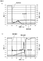
- (A) is a figure which shows the time-dependent change of the voltage and temperature of a battery at the time of performing a nail penetration test with respect to the lithium ion battery in the 1st Embodiment of this invention
- (b) is the conventional lithium
- It is a figure which shows the time-dependent change of the voltage and temperature of a battery at the time of performing a nail penetration test with respect to an ion battery.
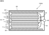
- It is sectional drawing which shows the structure of the lithium ion battery in the 2nd Embodiment of this invention.
- FIG. 1 is a cross-sectional view showing a structure of a lithium ion battery 100 according to the first embodiment.
- the lithium ion battery 100 includes an electrode body 10, an outer can 20 that houses the electrode body 10, and an insulating sheet 30.
- the outer can 20 is made of a metal such as stainless steel, aluminum, nickel, or iron, for example, and has one polarity of a positive electrode and a negative electrode.
- the outer can 20 is provided with a terminal 40 having a polarity different from that of itself.
- the outer can 20 functions as a negative electrode terminal having a negative polarity, and the terminal 40 is described as a positive electrode terminal.
- the exterior can 20 which is a negative electrode terminal and the terminal 40 which is a positive electrode terminal are electrically insulated.
- the insulating sheet 30 is coated with an insulating layer on the surface of an insulating plate such as a resin or the like, a porous film, a resin tape such as polyimide, polypropylene or acrylic, or a metal foil such as an aluminum foil, a copper foil, a stainless steel foil or a nickel foil. And a film composed of an insulating ceramic such as alumina and a binder.
- the insulating sheet 30 may be bonded to the surface of the outer can 20 or the electrode body 10. Further, the insulating sheet 30 may be the same as the separator 17 described later.
- a nonaqueous electrolyte solution (not shown) is also enclosed in the outer can 20.
- the nonaqueous electrolytic solution includes a solute and a solvent.
- a solute for example, a Li salt such as LiPF 6 or LiBF 4 is preferably used.
- the solvent for example, an organic solvent such as ethylene carbonate (EC), propylene carbonate (PC), dimethyl carbonate (DMC), ethyl methyl carbonate (EMC), and diethyl carbonate (DEC) is preferably used.
- the electrolyte may be a liquid or a polymer.
- the electrode body 10 is a laminated electrode body configured by alternately laminating a plurality of positive electrodes 11 and negative electrodes 14 via separators 17.
- the direction in which the positive electrode 11 and the negative electrode 14 are laminated is referred to as a lamination direction.
- the positive electrode 11 has a positive electrode active material 13 disposed on both surfaces of a positive electrode current collector 12 made of a metal foil such as aluminum.
- a positive electrode active material 13 for example, lithium cobaltate, lithium nickelate, lithium manganate, lithium iron phosphate, or a material obtained by replacing a part of these transition metals with another metal is used.
- the positive electrode active material 13 may be used alone or in combination of two or more of the above materials.
- Such a positive electrode active material 13 is mixed with a binder, a solvent, and the like, applied to the positive electrode current collector 11, dried, and then pressed to apply the positive electrode active material 13 to the surface of the positive electrode current collector 11. It is arranged.
- the negative electrode 14 has a negative electrode active material 16 disposed on both sides of a negative electrode current collector 15 made of a metal foil such as copper.
- the negative electrode active material 16 include carbon materials such as graphite (natural graphite, artificial graphite), hard carbon, and soft carbon, oxides such as silicon oxide, tin oxide, indium oxide, zinc oxide, and lithium oxide, Al, Si, A binary, ternary, or higher alloy of a metal such as Pb, Sn, In, Bi, Ag, Ba, Ca, Hg, Pd, Pt, Te, Zn, La, and lithium is used.
- the negative electrode active material 16 may be used alone or in combination of two or more of the above materials.
- Such a negative electrode active material 16 is mixed with a binder, a solvent, and the like, applied to the negative electrode current collector 15, dried, and then pressed to apply the negative electrode active material 16 to the surface of the negative electrode current collector 15. It is arranged.
- the electrode disposed on the outermost side of the electrode body 10 in the stacking direction is an electrode having a polarity different from that of the outer can 20.
- the electrode arranged on the outermost side of the electrode body 10 is a positive electrode.
- the positive electrode active material 13 is arranged only on one surface (one surface) of the positive electrode current collector 12. Specifically, the positive electrode active material 13 is disposed on the adjacent negative electrode 14 side surface (one surface) of both surfaces of the positive electrode current collector 12 of the positive electrode 11x, and the surface facing the outer can 20, that is, The positive electrode active material 13 is not disposed on the surface near the outer can 20 (the other surface). In addition, the thickness of the positive electrode current collector 12 of the positive electrode 11x is the same as the thickness of the positive electrode current collector 12 of the other positive electrode 11.
- All the positive electrode current collectors 12 are connected to terminals 40 which are positive electrode terminals through lead wires 18.
- all the negative electrode current collectors 15 are connected to an outer can 20 that is a negative electrode terminal via a lead wire 19.
- the negative electrode current collector 15 may be directly connected to the outer can 20 or may be electrically connected via another negative electrode terminal.
- the separator 17 a sheet-like material is used, and for example, it is constituted by a microporous thin film made of polypropylene having excellent insulating properties. Since the separator 17 is made of a microporous thin film, lithium ions permeate the separator 17.
- the separator 17 is not limited to a sheet-like thing,
- the bag-like form which can accommodate the positive electrode 11 or the negative electrode 14 separately may be sufficient, and a ninety-nine fold form may be sufficient as it. It may be a winding form.
- the surface of the separator 17 may be covered with an inorganic particle coat layer, an adhesive layer, or the like. Moreover, the surface of the separator 17 may have adhesiveness.
- the separator 17 may be a single layer film made of one kind of material, or may be a composite film or a multilayer film made of one kind or two or more kinds of materials.
- the insulating sheet 30, which is an insulator, is disposed between the electrode body 10 and the outer can 20 and between the positive electrode 11 x disposed on the outermost side of the electrode body 10 and the outer can 20. More specifically, the insulating sheet 30 is disposed between the positive electrode 11x and the outer can 20 in the stacking direction. The insulating sheet 30 electrically insulates the positive electrode 11x disposed on the outermost side of the electrode body 10 and the outer can 20 that is a negative electrode terminal.
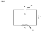
- FIG. 2 is a diagram showing an equivalent circuit when a short circuit occurs due to a conductive material such as a nail stuck in the battery.
- the voltage of the battery before the short circuit is E
- the current flowing at the time of the short circuit is I
- the internal resistance of the battery is Ri
- the short circuit resistance is Rs.
- Ri is a resistance value measured under the condition of 25 ° C. converted into a resistance value at the temperature at the time of short circuit.
- the heat generation amount of the battery is Wi
- the heat generation amount at the short-circuit portion is Ws.
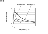
- FIG. 3 is a diagram showing the relationship between the short-circuit resistance Rs at the time of short-circuit and the heat generation amount Ws of the short-circuit portion for the battery with the internal resistance Ri1 and the battery with the internal resistance Ri2 larger than Ri1.
- the amount of heat generation Ws of the short circuit portion becomes maximum when the internal resistance Ri of the battery is equal to the short circuit resistance Rs.
- the position where the internal resistance Ri of the battery becomes equal to the short-circuit resistance Rs is indicated by a broken line.
- the lithium ion battery 100 in this embodiment first, a short circuit occurs between the positive electrode 11x disposed on the outermost side of the electrode body 10 and the outer can 20, so that the short circuit resistance Rs is within the battery. It becomes much smaller than the resistance Ri. Therefore, Joule heat generated at the short-circuit portion between the positive electrode 11x and the outer can 20 can be reduced.
- the positive electrode 11 and the negative electrode 14 inside the electrode body 10 are thereafter Even if a short circuit occurs between the electrodes, a large short-circuit current does not flow inside the electrode body 10, and Joule heat generated inside the electrode body 10 can be reduced. Furthermore, the positive electrode 11x disposed on the outermost side of the electrode body 10 does not have the positive electrode active material 13 disposed on the other surface facing the outer can 20, and thus the positive electrode collection of the positive electrode 11x disposed on the outermost side. First, a short circuit occurs between the electric body 12 and the outer can 20. Since a short circuit with the outer can 20 occurs between the positive electrode current collector 12 and the short circuit resistance, the short circuit current is easy to flow.
- the time-dependent changes in the voltage and temperature of the battery in the nail penetration test in which a nail was inserted from the outside of the lithium ion battery 100 were examined.
- a nail penetration test was also conducted on a conventional lithium ion battery in which an electrode having the same polarity as that of the outer can is arranged on the outermost side of the electrode body.
- FIG. 4A is a diagram showing changes over time in battery voltage and temperature when a nail penetration test is performed on the lithium ion battery 100 in this embodiment.
- FIG. 4B is a graph showing changes in battery voltage and temperature over time when a nail penetration test is performed on a conventional lithium ion battery. In either case, a nail was stabbed at a timing of 10 (sec).
- FIGS. 4A and 4B also show the environmental temperature when the nail penetration test is performed.
- the lithium ion battery 100 in this embodiment since a short circuit occurs between the positive electrode 11x disposed on the outermost side of the electrode body 10 and the outer can 20, a large current flows at the short circuit part, As shown to 4 (a), the voltage of a battery falls at a stretch. Thereby, the emitted-heat amount when the short circuit generate
- the thickness of the positive electrode current collector 12 of the positive electrode 11x arranged on the outermost side of the electrode body 10 is equal to the thickness of the positive electrode current collector 12 of the other positive electrode 11. It was the same.
- the thickness of the positive electrode current collector 12 a of the positive electrode 11 x disposed on the outermost side of the electrode body 10 is larger than the thickness of the positive electrode current collector 12 of the other positive electrode 11. It is also thickened.
- FIG. 5 is a cross-sectional view showing the structure of the lithium ion battery 100A in the second embodiment.
- the same components as those of the lithium ion battery 100 shown in FIG. 1 are identical to those of the lithium ion battery 100 shown in FIG. 1;
- the positive electrode active material 13 is arranged only on one side (one side) of the positive electrode current collector 12a. Specifically, the positive electrode active material 13 is disposed only on the adjacent negative electrode 14 side surface (one surface) of both surfaces of the positive electrode current collector 12a, and the surface facing the outer can 20 (the other surface). ) Is not provided with the positive electrode active material 13.
- the thickness of the positive electrode current collector 12a in the stacking direction is larger than the thickness of the positive electrode current collector 12 of the positive electrode 11 disposed on the inner side in the stacking direction than the positive electrode current collector 12a.
- the thickness of the positive electrode current collector 12 disposed on the inner side in the stacking direction than the positive electrode current collector 12a is 5 ⁇ m to 12 ⁇ m, and the thickness of the positive electrode current collector 12a is 15 ⁇ m to 50 ⁇ m.
- the resistance of the positive electrode current collector 12a can be reduced by increasing the thickness of the positive electrode current collector 12a disposed on the outermost side. Thereby, when a conductive material such as a nail is stabbed from the outside of the lithium ion battery 100A, the short-circuit resistance between the positive electrode 11x first short-circuited and the outer can 20 can be further reduced.
- the short circuit resistance is smaller than the internal resistance of the battery, the lower the short circuit resistance, the smaller the Joule heat generated at the short circuit part. Therefore, in the lithium ion battery 100A in the second embodiment, when a conductive material such as a nail is stabbed, the positive electrode 11x and the outer can 20 that are short-circuited first are compared with the lithium ion battery 100 in the first embodiment. Joule heat generated between the two can be further reduced.
- a short circuit occurs first between the positive electrode 11x disposed on the outermost side of the electrode body 10 and the outer can 20 and a short circuit current flows. Even if a short circuit occurs between the positive electrode 11 and the negative electrode 14 through the conductive material, a large short-circuit current does not flow inside the electrode body 10, and the Joule heat generated inside the electrode body 10 can be reduced. it can.
- the electrode body 10 It is possible to suppress the occurrence of warpage in the positive electrode 11b in which the positive electrode active material 13 is disposed only on one side during the formation of the film. Thereby, the lamination property of the electrode at the time of formation of the electrode body 10 can be improved.
- the electrode body 10 accommodated in the armored can 20 was a laminated electrode body.
- the electrode body accommodated in an armored can is the winding electrode body by which the positive electrode and negative electrode which pinched
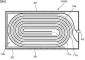
- FIG. 6 is a cross-sectional view showing the structure of a lithium ion battery 100B in the third embodiment having a configuration in which the wound electrode body 10b is housed in the outer can 20.
- the wound electrode body 10b is configured by winding a positive electrode 11b and a negative electrode 14b sandwiching a separator 17b therebetween in a spiral shape.
- the positive electrode 11b is formed by coating a positive electrode active material on both surfaces of a positive electrode current collector made of a metal foil such as aluminum
- the negative electrode 14b is made of a negative electrode current collector made of a metal foil such as copper. It is formed by coating a negative electrode active material on both sides.
- the positive electrode active material and the negative electrode active material are omitted.
- FIG. 6 shows a configuration in which the winding end surface (the surface in which the winding state is understood) of the wound electrode body 10b is stored without matching the surface on which the terminal 40 of the outer can 20 is formed.
- the form is not limited to this. It is also possible to store the wound end face of the wound electrode body 10b so as to coincide with the face on which the terminal 40 of the outer can 20 is formed. In this case, the terminal 40 and the electrode body 10 are electrically connected by a separate connection lead.
- the outer can 20 is a negative electrode terminal and the terminal 40 is a positive electrode terminal. Therefore, the positive electrode 11 b is electrically connected to the terminal 40, and the negative electrode 14 b is electrically connected to the outer can 20.
- the electrode located on the outermost side of the wound electrode body 10b is an electrode having a polarity different from that of the outer can 20. Therefore, the electrode located on the outermost side of the wound electrode body 10b is the positive electrode 11b.
- An insulating sheet 30 is disposed between the electrode 11b, which is an electrode located on the outermost side of the wound electrode body 10b, and the outer can 20.
- the positive electrode 11b and the outer can 20 that are located on the outermost side of the wound electrode body 10 are interposed through the conductive material.
- a short circuit occurs first, so that, similarly to the first and second embodiments, Joule heat generated inside the wound electrode body 10b can be reduced, and high safety can be ensured. .
- the two electrodes arranged on the outermost side of the electrode body 10 in the stacking direction are both electrodes having a polarity different from that of the outer can 20.
- only one of the two electrodes arranged on the outermost side of the electrode body 10 in the stacking direction may be an electrode having a polarity different from that of the outer can 20.
- the battery according to the present invention when the battery according to the present invention is housed in an electronic device and used, only the electrode close to the outside of the electronic device out of the two electrodes arranged on the outermost side of the electrode body in the stacking direction is packaged.
- the electrode can have a polarity different from that of the can.
- Joule heat generated inside the battery can be reduced, and high safety can be ensured.
- the outer can 20 is a negative electrode terminal and the terminal 40 is a positive electrode terminal, but the outer can 20 may be a positive electrode terminal and the terminal 40 may be a negative electrode terminal. In that case, the electrode arranged on the outermost side of the electrode body 10 is a negative electrode.
- a lithium ion battery has been described as an example, but a battery other than a lithium ion battery may be used.
- a conductive material such as a nail is externally provided at the position where the electrode is disposed.
- a short circuit first occurs between the electrode and the outer can. Since this short circuit resistance is much smaller than the internal resistance of the battery, Joule heat generated at the short circuit portion can be reduced.
- a conductive material is then interposed between the positive electrode and the negative electrode inside the electrode body. Even if a short circuit occurs, a large short circuit current does not flow inside the electrode body, and Joule heat generated inside the electrode body can be reduced. Thereby, high safety can be ensured.
- the electrode body is a laminated electrode body in which a plurality of positive electrodes and negative electrodes are alternately laminated via separators, and an electrode having a polarity different from that of the outer can is disposed on the outermost side in the laminating direction of the laminated electrode body.
- Each of the positive electrode and the negative electrode has a metal foil and an active material disposed on the metal foil, and the metal foil of the electrode disposed on the outermost side in the stacking direction of the stacked electrode body is more than the metal foil.
- the electrode body is a wound electrode body in which a positive electrode and a negative electrode are wound with a separator interposed therebetween, a joule generated inside the electrode body when a conductive material such as a nail is stabbed from the outside. Heat can be reduced and high safety can be ensured.
Landscapes
- Chemical & Material Sciences (AREA)
- Chemical Kinetics & Catalysis (AREA)
- Electrochemistry (AREA)
- General Chemical & Material Sciences (AREA)
- Engineering & Computer Science (AREA)
- Manufacturing & Machinery (AREA)
- Secondary Cells (AREA)
- Materials Engineering (AREA)
- Battery Electrode And Active Subsutance (AREA)
- Connection Of Batteries Or Terminals (AREA)
Abstract
釘などの導電物が刺さって内部短絡が生じた場合でも、高い安全性を確保することができる電池を提供する。 電池100は、正極11、負極14、および正極11と負極14との間に配置されているセパレータ17を有する電極体10と、電極体10を収納し、正極11および負極14のうちの一方の極性を有する外装缶20とを備える。電極体10の最も外側には、外装缶20と異なる極性の電極が少なくとも一つ配置されている。外装缶20と異なる極性を有し電極体10の最も外側に位置する電極は、金属箔と、金属箔の一方の面に配置された活物質とを有し、外装缶20に近い側の面である金属箔の他方の面に活物質が配置されていない。電池100はさらに、外装缶20と異なる極性を有し電極体10の最も外側に位置する電極の金属箔の他方の面と、外装缶20との間に配置されている絶縁シート30をさらに備える。
Description
本発明は、電極体を外装缶に収納した構造の電池に関する。
正極および負極を有する電極体を外装缶に収容した構造の電池が知られている。
特許文献1には、正極シートと負極シートとの間にセパレータシートを挟んで複数積層した電極体を外装缶に収容し、蓋部材で外装缶の開口部を密封した構成の電池が開示されている。この電池では、正極シートを、蓋部材の中央の端子部と電気的に接続し、負極シートを外装缶と電気的に接続している。また、外装缶と、最外層の電極シートとの間の短絡を防ぐために、最外層の電極シートを、外装缶と同じ極性である負極シートとしている。
しかしながら、特許文献1に記載の電池に対して釘などの導電物が刺さった場合、導電物を介して電極体内部の正極シートと負極シートが短絡するため、電極体内部で大きいジュール熱が発生し、電池の安全性が問題になる。
本発明は、上記課題を解決するものであり、釘などの導電物が刺さって内部短絡が生じた場合でも、高い安全性を確保することができる電池を提供することを目的とする。
本発明の電池は、正極、負極、および前記正極と前記負極との間に配置されているセパレータを有する電極体と、前記電極体を収納し、前記正極および前記負極のうちの一方の極性を有する外装缶と、を備え、前記電極体の最も外側には、前記外装缶と異なる極性の電極が少なくとも一つ配置されており、前記外装缶と異なる極性を有し前記電極体の最も外側に位置する電極は、金属箔と、前記金属箔の一方の面に配置された活物質とを有し、前記外装缶に近い側の面である前記金属箔の他方の面に活物質は配置されておらず、前記外装缶と異なる極性を有し前記電極体の最も外側に位置する電極の前記金属箔の他方の面と、前記外装缶との間に配置されている絶縁体をさらに備える、ことを特徴とする。
前記電極体は、前記正極および前記負極が前記セパレータを介して交互に複数積層された積層電極体であり、前記積層電極体の積層方向における最も外側に、前記外装缶と異なる極性の電極が配置されている構成としてもよい。
また、前記正極および前記負極はそれぞれ、金属箔と、前記金属箔に配置された活物質とを有し、前記積層電極体の積層方向における最も外側に配置されている電極の金属箔は、当該金属箔よりも積層方向内側に配置されている電極の金属箔よりも厚い構成としてもよい。
また、前記電極体は、前記セパレータを間に挟んだ前記正極および前記負極が巻回された巻回電極体である構成としてもよい。
本発明によれば、電極体の最も外側に、外装缶と異なる極性の電極が少なくとも一つ配置されているので、その電極が配置されている位置に外部から釘などの導電物が刺さった場合、その電極と外装缶との間で最初に短絡が生じる。この短絡抵抗は、電池の内部抵抗より非常に小さいので、短絡部分で発生するジュール熱を小さくすることができる。また、電極体の最も外側に配置されている電極と外装缶との間で最初に短絡が生じて短絡電流が流れるため、その後に電極体の内部の正極と負極との間で導電物を介して短絡が生じても、電極体の内部で大きい短絡電流は流れず、電極体の内部で発生するジュール熱を小さくすることができる。これにより、高い安全性を確保することができる。さらに電極体の最も外側に配置されている電極は、外装缶と対向する他方の面に活物質が配置されていないため、最も外側に配置されている電極の金属箔と外装缶との間に最初に短絡が生じる。外装缶との短絡が金属箔との間で生じるため、短絡抵抗が非常に小さく、短絡電流が流れやすい。
以下に本発明の実施形態を示して、本発明の特徴とするところをさらに具体的に説明する。以下では、本発明の電池として、リチウムイオン電池を例に挙げて説明する。
[第1の実施形態]
図1は、第1の実施形態におけるリチウムイオン電池100の構造を示す断面図である。リチウムイオン電池100は、電極体10と、電極体10を収納する外装缶20と、絶縁シート30とを備える。
図1は、第1の実施形態におけるリチウムイオン電池100の構造を示す断面図である。リチウムイオン電池100は、電極体10と、電極体10を収納する外装缶20と、絶縁シート30とを備える。
外装缶20は、例えばステンレス、アルミニウム、ニッケル、鉄などの金属からなり、正極および負極のうちの一方の極性を有する。外装缶20には、自身と極性が異なる端子40が設けられている。この実施形態では、外装缶20は負極の極性を有する負極端子として機能し、端子40は正極端子であるものとして説明する。負極端子である外装缶20と、正極端子である端子40との間は、電気的に絶縁されている。
絶縁シート30は、例えば樹脂などの絶縁性の板や多孔質膜、ポリイミド、ポリプロピレン、アクリル等の樹脂テープ、アルミ箔、銅箔、ステンレス箔、ニッケル箔等の金属箔の表面を絶縁層によりコーティングしたもの、アルミナなどの絶縁性セラミックと結着剤により構成された膜などが挙げられる。絶縁シート30は、外装缶20や電極体10の表面に接合していてもよい。また、絶縁シート30として、後述するセパレータ17と同じものが用いられてもよい。
外装缶20の内部には、電極体10および絶縁シート30以外に、非水電解液(不図示)も封入されている。非水電解液は、溶質と溶媒を含む。溶質には、例えば、LiPF6やLiBF4などのLi塩が好ましく用いられる。溶媒には、例えば、エチレンカーボネート(EC)、プロピレンカーボネート(PC)、ジメチルカーボネート(DMC)、エチルメチルカーボネート(EMC)、ジエチルカーボネート(DEC)などの有機溶媒が好ましく用いられる。電解質は液体でもよいし、ポリマー状のものを用いてもよい。
電極体10は、図1に示すように、正極11と負極14とがセパレータ17を介して交互に複数積層されることによって構成された積層電極体である。本明細書では、正極11および負極14が積層されている方向を積層方向と呼ぶ。
正極11は、アルミニウムなどの金属箔からなる正極集電体12の両面に、正極活物質13が配置されている。正極活物質13としては、例えばコバルト酸リチウム、ニッケル酸リチウム、マンガン酸リチウム、リン酸鉄リチウム、または、それらの遷移金属の一部を別の金属で置き換えたものが用いられている。正極活物質13は、上記材料のうちの一種類を単独で用いてもよいし、二種類以上を組み合わせて用いてもよい。このような正極活物質13を結着剤および溶剤等と混合して正極集電体11に塗工し、乾燥した後、加圧することにより、正極集電体11の表面に正極活物質13を配置させている。
負極14は、銅などの金属箔からなる負極集電体15の両面に、負極活物質16が配置されている。負極活物質16としては、例えば黒鉛(天然黒鉛、人造黒鉛)、ハードカーボン、ソフトカーボンなどの炭素材料、酸化シリコン、酸化スズ、酸化インジウム、酸化亜鉛および酸化リチウムなどの酸化物、Al、Si、Pb、Sn、In、Bi、Ag、Ba、Ca、Hg、Pd、Pt、Te、Zn、Laなどの金属とリチウムとの2元、3元またはそれ以上の合金が用いられている。負極活物質16は、上記材料のうちの一種類を単独で用いてもよいし、二種類以上を組み合わせて用いてもよい。このような負極活物質16を結着剤および溶剤等と混合して負極集電体15に塗工し、乾燥した後、加圧することにより、負極集電体15の表面に負極活物質16を配置させている。
積層方向における電極体10の最も外側に配置されている電極は、外装缶20と異なる極性の電極である。この実施形態では、外装缶20が負極端子として機能するため、電極体10の最も外側に配置されている電極は正極である。
電極体10の最も外側に配置されている正極11xは、正極集電体12の片面(一方の面)にのみ正極活物質13が配置されている。具体的には、正極11xの正極集電体12の両面のうち、隣接する負極14側の面(一方の面)に正極活物質13が配置されており、外装缶20に対向する面、すなわち外装缶20に近い側の面(他方の面)には正極活物質13は配置されていない。なお、正極11xの正極集電体12の厚さは、それ以外の正極11の正極集電体12の厚さと同じである。
全ての正極集電体12は、リード線18を介して、正極端子である端子40と接続されている。また、全ての負極集電体15は、リード線19を介して、負極端子である外装缶20と接続されている。負極集電体15は、外装缶20に直接接続されていてもよいし、別の負極端子を介して電気的に接続されていてもよい。
セパレータ17としては、シート状のものが用いられており、例えば、絶縁性に優れたポリプロピレン製の微多孔性薄膜によって構成されている。セパレータ17が微多孔性薄膜によって構成されていることにより、リチウムイオンはセパレータ17を透過する。
なお、セパレータ17は、シート状のものに限定されることはなく、正極11または負極14を個別に収容可能な袋状の形態であってもよいし、九十九折りの形態であってもよいし、巻回の形態であってもよい。セパレータ17の表面は、無機粒子コート層や接着層等により覆われていてもよい。また、セパレータ17の表面は、接着性を有していてもよい。セパレータ17は1種類の材料からなる単層膜であってもよく、1種類または2種類以上の材料からなる複合膜または多層膜であってもよい。
絶縁体である絶縁シート30は、電極体10と外装缶20との間であって、電極体10の最も外側に配置されている正極11xと外装缶20との間に配置されている。より具体的には、絶縁シート30は、積層方向における正極11xと外装缶20との間に配置されている。絶縁シート30によって、電極体10の最も外側に配置されている正極11xと、負極端子である外装缶20との間は、電気的に絶縁されている。
ここで、電池の外部から釘などの導電物が刺さって短絡が生じる場合について考察する。
図2は、電池に釘などの導電物が刺さって短絡が生じた場合の等価回路を示す図である。図2において、短絡前の電池の電圧をE、短絡時に流れる電流をI、電池の内部抵抗をRi、短絡抵抗をRsとしている。ただし、Riは25℃の条件下で測定される抵抗値を短絡時の温度における抵抗値に換算したものである。また、電池の発熱量をWi、短絡部での発熱量をWsとしている。
図3は、内部抵抗Ri1の電池と、Ri1よりも大きい内部抵抗Ri2の電池について、短絡時の短絡抵抗Rsと短絡部の発熱量Wsとの関係を示す図である。短絡部の発熱量Wsは、電池の内部抵抗Riが短絡抵抗Rsと等しい場合に最大となる。図3では、電池の内部抵抗Riが短絡抵抗Rsと等しくなる位置を破線で示している。
ここで、この実施形態におけるリチウムイオン電池100では、まず初めに、電極体10の最も外側に配置されている正極11xと外装缶20との間で短絡が生じるので、短絡抵抗Rsが電池の内部抵抗Riより非常に小さくなる。したがって、正極11xと外装缶20との間における短絡部分で発生するジュール熱を小さくすることができる。また、最初に電極体10の最も外側に配置されている正極11xと外装缶20との間で短絡が生じて短絡電流が流れるため、その後に電極体10の内部の正極11と負極14との間で導電物を介して短絡が生じても、電極体10の内部で大きい短絡電流は流れず、電極体10の内部で発生するジュール熱を小さくすることができる。さらに、電極体10の最も外側に配置されている正極11xは、外装缶20と対向する他方の面に正極活物質13が配置されていないため、最も外側に配置されている正極11xの正極集電体12と外装缶20との間に最初に短絡が生じる。外装缶20との短絡が正極集電体12との間で生じるため、短絡抵抗が非常に小さく、短絡電流が流れやすい。
この実施形態におけるリチウムイオン電池100の外側から釘を刺す釘刺し試験を行った場合の電池の電圧および温度の経時変化について調べた。また、比較のために、電極体の最も外側に、外装缶と同じ極性の電極が配置されている従来のリチウムイオン電池についても釘刺し試験を行った。
図4(a)は、この実施形態におけるリチウムイオン電池100に対して釘刺し試験を行った場合の電池の電圧および温度の経時変化を示す図である。また、図4(b)は、従来のリチウムイオン電池に対して釘刺し試験を行った場合の電池の電圧および温度の経時変化を示す図である。いずれの場合も、10(sec)のタイミングで釘を刺した。なお、図4(a)および図4(b)には、釘刺し試験を行ったときの環境温度も示している。
図4(b)に示すように、従来のリチウムイオン電池に釘を刺す試験を行った場合、電極体の最も外側に配置されている電極と外装缶の極性は同じであるため、その部分では短絡は生じず、電極体の内部の正極と負極とが短絡する。このため、電池の温度は500℃近くまで上昇し、電池内部で発火が生じた。
一方、この実施形態におけるリチウムイオン電池100では、電極体10の最も外側に配置されている正極11xと外装缶20との間で短絡が発生するので、その短絡部位で大電流が流れて、図4(a)に示すように、電池の電圧は一気に低下する。これにより、電極体10内部の正極11と負極14との間で短絡が発生したときの発熱量を抑制することができる。したがって、釘を刺した後に電池の温度が100℃を超えることはなく、また発火や発煙が発生することもなかった。
[第2の実施形態]
第1の実施形態におけるリチウムイオン電池100では、電極体10の最も外側に配置されている正極11xの正極集電体12の厚さは、それ以外の正極11の正極集電体12の厚さと同じであった。第2の実施形態におけるリチウムイオン電池100Aでは、電極体10の最も外側に配置されている正極11xの正極集電体12aの厚さは、それ以外の正極11の正極集電体12の厚さよりも厚くされている。
第1の実施形態におけるリチウムイオン電池100では、電極体10の最も外側に配置されている正極11xの正極集電体12の厚さは、それ以外の正極11の正極集電体12の厚さと同じであった。第2の実施形態におけるリチウムイオン電池100Aでは、電極体10の最も外側に配置されている正極11xの正極集電体12aの厚さは、それ以外の正極11の正極集電体12の厚さよりも厚くされている。
図5は、第2の実施形態におけるリチウムイオン電池100Aの構造を示す断面図である。図5に示すリチウムイオン電池100Aの構成のうち、図1に示すリチウムイオン電池100の構成と同じ構成部分については、同一の符号を付して詳しい説明は省略する。
積層方向における電極体10の最も外側に配置されている正極11xは、正極集電体12aの片面(一方の面)にのみ正極活物質13が配置されている。具体的には、正極集電体12aの両面のうち、隣接する負極14側の面(一方の面)にのみ正極活物質13が配置されており、外装缶20に対向する面(他方の面)には正極活物質13は配置されていない。
正極集電体12aの積層方向における厚さは、正極集電体12aよりも積層方向内側に配置されている正極11の正極集電体12の厚さに比べて厚くされている。例えば、正極集電体12aよりも積層方向内側に配置されている正極集電体12の厚さは5μm以上12μm以下であり、正極集電体12aの厚さは15μm以上50μm以下である。
金属箔からなる集電体の抵抗率をρ、長さをL、断面積をSとすると、集電体の抵抗Rは、次式(1)により表される。
R=ρ・L/S …(1)
R=ρ・L/S …(1)
集電体の厚さを厚くすると、断面積Sが大きくなるので、式(1)から明らかなように、集電体の抵抗Rは小さくなる。
すなわち、最も外側に配置されている正極集電体12aの厚さを厚くすることにより、正極集電体12aの抵抗を小さくすることができる。これにより、リチウムイオン電池100Aの外側から、釘などの導電物が刺さった場合に、最初に短絡する正極11xと外装缶20との間の短絡抵抗をさらに小さくすることができる。
図3に示すように、短絡抵抗が電池の内部抵抗よりも小さい場合には、短絡抵抗が小さくなるほど、短絡部で発生するジュール熱は小さくなる。したがって、第2の実施形態におけるリチウムイオン電池100Aでは、釘などの導電物が刺さった場合に、第1の実施形態におけるリチウムイオン電池100と比べて、最初に短絡する正極11xと外装缶20との間で発生するジュール熱をさらに小さくすることができる。
また、第1の実施形態と同様に、最初に電極体10の最も外側に配置されている正極11xと外装缶20との間で短絡が生じて短絡電流が流れるため、その後に電極体10の内部の正極11と負極14との間で導電物を介して短絡が生じても、電極体10の内部で大きい短絡電流は流れず、電極体10の内部で発生するジュール熱を小さくすることができる。
また、最も外側に配置されている正極集電体12bの厚さを、電極体10の積層方向内側に配置されている他の正極集電体12の厚さよりも厚くすることにより、電極体10の形成時に、片面にしか正極活物質13が配置されていない正極11bに反りが発生するのを抑制することができる。これにより、電極体10の形成時における電極の積層性を向上させることができる。
[第3の実施形態]
第1および第2の実施形態では、外装缶20に収納される電極体10は積層電極体であった。第3の実施形態では、外装缶に収納される電極体は、セパレータを間に挟んだ正極および負極が巻回された巻回電極体である。
第1および第2の実施形態では、外装缶20に収納される電極体10は積層電極体であった。第3の実施形態では、外装缶に収納される電極体は、セパレータを間に挟んだ正極および負極が巻回された巻回電極体である。
図6は、巻回電極体10bを外装缶20に収納した構成の第3の実施形態におけるリチウムイオン電池100Bの構造を示す断面図である。巻回電極体10bは、セパレータ17bを間に挟んだ正極11bおよび負極14bが渦巻き状に巻回されて構成されている。正極11bは、アルミニウムなどの金属箔からなる正極集電体の両面に、正極活物質が塗工されることによって形成されており、負極14bは、銅などの金属箔からなる負極集電体の両面に、負極活物質が塗工されることによって形成されている。なお、図6では、正極活物質および負極活物質は省略している。
また、図6では、巻回電極体10bの巻回端面(巻回状態がわかる面)を外装缶20の端子40が形成された面と一致させずに収納した構成を示しているが、収納形態はこれに限らない。巻回電極体10bの巻回端面を外装缶20の端子40が形成された面と一致させるように収納することも可能である。この場合、端子40と電極体10とは別体の接続リードで電気的に接続される。
本実施形態でも、外装缶20が負極端子であり、端子40は正極端子であるものとして説明する。したがって、正極11bは端子40と電気的に接続されており、負極14bは外装缶20と電気的に接続されている。
第1および第2の実施形態と同様に、巻回電極体10bの最も外側に位置する電極は、外装缶20と異なる極性の電極である。したがって、巻回電極体10bの最も外側に位置する電極は、正極11bである。巻回電極体10bの最も外側に位置する電極である電極11bと外装缶20との間には、絶縁シート30が配置されている。
第3の実施形態におけるリチウムイオン電池100Bでも、外側から釘などの導電物が刺さった場合に、その導電物を介して、巻回電極体10の最も外側に位置する正極11bと外装缶20との間で最初に短絡が生じるので、第1および第2の実施形態と同様に、巻回電極体10bの内部で発生するジュール熱を小さくすることができ、高い安全性を確保することができる。
ここで、上述した第1および第2の実施形態では、積層方向における電極体10の最も外側に配置されている2つの電極がともに、外装缶20と異なる極性の電極であるものとして説明した。しかし、積層方向における電極体10の最も外側に配置されている2つの電極のうちの1つの電極のみを外装缶20と異なる極性の電極としてもよい。例えば、本発明による電池が電子機器の内部に収容されて用いられる場合に、積層方向における電極体の最も外側に配置されている2つの電極のうち、電子機器の外側に近い電極のみを、外装缶と異なる極性の電極とすることができる。この場合も、電子機器の外側から釘などの導電物が刺さった場合に、電池内部で発生するジュール熱を小さくすることができ、高い安全性を確保することができる。
上述した各実施形態では、外装缶20が負極端子であり、端子40は正極端子としたが、外装缶20が正極端子であり、端子40は負極端子であってもよい。その場合、電極体10の最も外側に配置されている電極は負極となる。
上述した実施形態では、リチウムイオン電池を例に挙げて説明したが、リチウムイオン電池以外の電池であってもよい。
本発明による電池によれば、電極体の最も外側には、外装缶と異なる極性の電極が少なくとも一つ配置されているので、その電極が配置されている位置に外部から釘などの導電物が刺さった場合、その電極と外装缶との間で最初に短絡が生じる。この短絡抵抗は、電池の内部抵抗より非常に小さいので、短絡部分で発生するジュール熱を小さくすることができる。また、電極体の最も外側に配置されている電極と外装缶との間で最初に短絡が生じて短絡電流が流れるため、その後に電極体の内部の正極と負極との間で導電物を介して短絡が生じても、電極体の内部で大きい短絡電流は流れず、電極体の内部で発生するジュール熱を小さくすることができる。これにより、高い安全性を確保することができる。
また、電極体は、正極および負極がセパレータを介して交互に複数積層された積層電極体であり、積層電極体の積層方向における最も外側に、外装缶と異なる極性の電極が配置されている構成とすることにより、積層方向の両外側のうちのどちら側から釘などの導電物が刺さっても、電極体の内部で発生するジュール熱を小さくすることができ、高い安全性を確保することができる。
また、正極および負極はそれぞれ、金属箔と、金属箔に配置された活物質とを有し、積層電極体の積層方向における最も外側に配置されている電極の金属箔は、当該金属箔よりも積層方向内側に配置されている電極の金属箔よりも厚い構成とすることにより、最も外側に配置されている電極の金属箔の抵抗を小さくすることができる。これにより、最初に短絡が生じる、最も外側に配置されている電極と外装缶との間の短絡抵抗をさらに小さくすることができ、その短絡部分で発生するジュール熱を小さくすることができる。
また、電極体が、セパレータを間に挟んだ正極および負極が巻回された巻回電極体であっても、外部から釘などの導電物が刺さった場合に、電極体の内部で発生するジュール熱を小さくすることができ、高い安全性を確保することができる。
本発明は、さらにその他の点においても上記実施形態に限定されるものではなく、本発明の範囲内において、種々の応用、変形を加えることが可能である。
10,10b 電極体
11,11b 正極
11x 最も外側に配置されている正極
12,12a 正極集電体
13 正極活物質
14 負極
15 負極集電体
16 負極活物質
17 セパレータ
20 外装缶
30 絶縁シート
40 端子
100,100A,100B リチウムイオン電池
11,11b 正極
11x 最も外側に配置されている正極
12,12a 正極集電体
13 正極活物質
14 負極
15 負極集電体
16 負極活物質
17 セパレータ
20 外装缶
30 絶縁シート
40 端子
100,100A,100B リチウムイオン電池
Claims (4)
- 正極、負極、および前記正極と前記負極との間に配置されているセパレータを有する電極体と、
前記電極体を収納し、前記正極および前記負極のうちの一方の極性を有する外装缶と、
を備え、
前記電極体の最も外側には、前記外装缶と異なる極性の電極が少なくとも一つ配置されており、
前記外装缶と異なる極性を有し前記電極体の最も外側に位置する電極は、金属箔と、前記金属箔の一方の面に配置された活物質とを有し、前記外装缶に近い側の面である前記金属箔の他方の面に活物質は配置されておらず、
前記外装缶と異なる極性を有し前記電極体の最も外側に位置する電極の前記金属箔の他方の面と、前記外装缶との間に配置されている絶縁体をさらに備える、
ことを特徴とする電池。 - 前記電極体は、前記正極および前記負極が前記セパレータを介して交互に複数積層された積層電極体であり、
前記積層電極体の積層方向における最も外側に、前記外装缶と異なる極性の電極が配置されている、
ことを特徴とする請求項1に記載の電池。 - 前記正極および前記負極はそれぞれ、金属箔と、前記金属箔に配置された活物質とを有し、
前記積層電極体の積層方向における最も外側に配置されている電極の金属箔は、当該金属箔よりも積層方向内側に配置されている電極の金属箔よりも厚い、
ことを特徴とする請求項2に記載の電池。 - 前記電極体は、前記セパレータを間に挟んだ前記正極および前記負極が巻回された巻回電極体である、
ことを特徴とする請求項1に記載の電池。
Applications Claiming Priority (2)
| Application Number | Priority Date | Filing Date | Title |
|---|---|---|---|
| JP2016-108344 | 2016-05-31 | ||
| JP2016108344A JP2019145199A (ja) | 2016-05-31 | 2016-05-31 | 電池 |
Publications (1)
| Publication Number | Publication Date |
|---|---|
| WO2017208507A1 true WO2017208507A1 (ja) | 2017-12-07 |
Family
ID=60479439
Family Applications (1)
| Application Number | Title | Priority Date | Filing Date |
|---|---|---|---|
| PCT/JP2017/005173 Ceased WO2017208507A1 (ja) | 2016-05-31 | 2017-02-13 | 電池 |
Country Status (2)
| Country | Link |
|---|---|
| JP (1) | JP2019145199A (ja) |
| WO (1) | WO2017208507A1 (ja) |
Cited By (1)
| Publication number | Priority date | Publication date | Assignee | Title |
|---|---|---|---|---|
| WO2026077130A1 (zh) * | 2024-10-11 | 2026-04-16 | 宁德新能源科技有限公司 | 二次电池、用电设备及二次电池的制备方法 |
Families Citing this family (2)
| Publication number | Priority date | Publication date | Assignee | Title |
|---|---|---|---|---|
| JP7429855B2 (ja) * | 2019-10-31 | 2024-02-09 | 株式会社村田製作所 | 二次電池および電池パック |
| CN119234340A (zh) * | 2023-04-28 | 2024-12-31 | 株式会社Lg新能源 | 包括具有绝缘涂层的正极的电极组件及其制造方法 |
Citations (3)
| Publication number | Priority date | Publication date | Assignee | Title |
|---|---|---|---|---|
| JPH08153542A (ja) * | 1994-09-27 | 1996-06-11 | Asahi Chem Ind Co Ltd | 非水系電池 |
| US20090011329A1 (en) * | 2007-07-03 | 2009-01-08 | Samsung Sdi Co., Ltd. | Secondary battery |
| JP2009224276A (ja) * | 2008-03-18 | 2009-10-01 | Hitachi Maxell Ltd | 扁平角型電池 |
-
2016
- 2016-05-31 JP JP2016108344A patent/JP2019145199A/ja active Pending
-
2017
- 2017-02-13 WO PCT/JP2017/005173 patent/WO2017208507A1/ja not_active Ceased
Patent Citations (3)
| Publication number | Priority date | Publication date | Assignee | Title |
|---|---|---|---|---|
| JPH08153542A (ja) * | 1994-09-27 | 1996-06-11 | Asahi Chem Ind Co Ltd | 非水系電池 |
| US20090011329A1 (en) * | 2007-07-03 | 2009-01-08 | Samsung Sdi Co., Ltd. | Secondary battery |
| JP2009224276A (ja) * | 2008-03-18 | 2009-10-01 | Hitachi Maxell Ltd | 扁平角型電池 |
Cited By (1)
| Publication number | Priority date | Publication date | Assignee | Title |
|---|---|---|---|---|
| WO2026077130A1 (zh) * | 2024-10-11 | 2026-04-16 | 宁德新能源科技有限公司 | 二次电池、用电设备及二次电池的制备方法 |
Also Published As
| Publication number | Publication date |
|---|---|
| JP2019145199A (ja) | 2019-08-29 |
Similar Documents
| Publication | Publication Date | Title |
|---|---|---|
| JP6640690B2 (ja) | 電極構造体、二次電池、電池パック及び車両 | |
| JP6288057B2 (ja) | 積層型全固体電池 | |
| JP4038699B2 (ja) | リチウムイオン電池 | |
| JP6938844B2 (ja) | 蓄電素子 | |
| JP6669122B2 (ja) | 積層電池 | |
| US10283747B2 (en) | Nonaqueous electrolyte secondary battery and battery pack | |
| US9887404B2 (en) | Secondary battery | |
| US20230036396A1 (en) | Secondary battery | |
| US11063327B2 (en) | Secondary battery and secondary battery control method | |
| WO2017014245A1 (ja) | リチウムイオン二次電池 | |
| US20170187025A1 (en) | Secondary battery | |
| JP2019192564A (ja) | 全固体電池 | |
| JP6674657B2 (ja) | 蓄電素子 | |
| JP2018195528A (ja) | 全固体電池 | |
| JP2017143006A (ja) | 蓄電素子 | |
| CN110120489A (zh) | 层叠电池 | |
| JP4720384B2 (ja) | バイポーラ電池 | |
| WO2017208507A1 (ja) | 電池 | |
| JP6507679B2 (ja) | リチウムイオン二次電池 | |
| JP2019140079A (ja) | 積層電池 | |
| US10854867B2 (en) | Stacked battery | |
| JP6977300B2 (ja) | 全固体電池 | |
| JP2018063872A (ja) | リチウムイオン二次電池 | |
| JP2010033888A (ja) | 非水電解質電池用リード線および非水電解質電池 | |
| JP2017168281A (ja) | 電源システム、自動車 |
Legal Events
| Date | Code | Title | Description |
|---|---|---|---|
| NENP | Non-entry into the national phase |
Ref country code: DE |
|
| 121 | Ep: the epo has been informed by wipo that ep was designated in this application |
Ref document number: 17806069 Country of ref document: EP Kind code of ref document: A1 |
|
| 122 | Ep: pct application non-entry in european phase |
Ref document number: 17806069 Country of ref document: EP Kind code of ref document: A1 |
|
| NENP | Non-entry into the national phase |
Ref country code: JP |