WO2017208479A1 - カード処理装置および自動取引装置 - Google Patents
カード処理装置および自動取引装置 Download PDFInfo
- Publication number
- WO2017208479A1 WO2017208479A1 PCT/JP2016/083958 JP2016083958W WO2017208479A1 WO 2017208479 A1 WO2017208479 A1 WO 2017208479A1 JP 2016083958 W JP2016083958 W JP 2016083958W WO 2017208479 A1 WO2017208479 A1 WO 2017208479A1
- Authority
- WO
- WIPO (PCT)
- Prior art keywords
- magnetic
- card
- opening
- unit
- information
- Prior art date
- Legal status (The legal status is an assumption and is not a legal conclusion. Google has not performed a legal analysis and makes no representation as to the accuracy of the status listed.)
- Ceased
Links
Images






Classifications
-
- G—PHYSICS
- G06—COMPUTING OR CALCULATING; COUNTING
- G06K—GRAPHICAL DATA READING; PRESENTATION OF DATA; RECORD CARRIERS; HANDLING RECORD CARRIERS
- G06K7/00—Methods or arrangements for sensing record carriers, e.g. for reading patterns
- G06K7/08—Methods or arrangements for sensing record carriers, e.g. for reading patterns by means detecting the change of an electrostatic or magnetic field, e.g. by detecting change of capacitance between electrodes
-
- G—PHYSICS
- G06—COMPUTING OR CALCULATING; COUNTING
- G06K—GRAPHICAL DATA READING; PRESENTATION OF DATA; RECORD CARRIERS; HANDLING RECORD CARRIERS
- G06K13/00—Conveying record carriers from one station to another, e.g. from stack to punching mechanism
- G06K13/02—Conveying record carriers from one station to another, e.g. from stack to punching mechanism the record carrier having longitudinal dimension comparable with transverse dimension, e.g. punched card
- G06K13/06—Guiding cards; Checking correct operation of card-conveying mechanisms
-
- G—PHYSICS
- G06—COMPUTING OR CALCULATING; COUNTING
- G06K—GRAPHICAL DATA READING; PRESENTATION OF DATA; RECORD CARRIERS; HANDLING RECORD CARRIERS
- G06K19/00—Record carriers for use with machines and with at least a part designed to carry digital markings
- G06K19/06—Record carriers for use with machines and with at least a part designed to carry digital markings characterised by the kind of the digital marking, e.g. shape, nature, code
-
- G—PHYSICS
- G06—COMPUTING OR CALCULATING; COUNTING
- G06Q—INFORMATION AND COMMUNICATION TECHNOLOGY [ICT] SPECIALLY ADAPTED FOR ADMINISTRATIVE, COMMERCIAL, FINANCIAL, MANAGERIAL OR SUPERVISORY PURPOSES; SYSTEMS OR METHODS SPECIALLY ADAPTED FOR ADMINISTRATIVE, COMMERCIAL, FINANCIAL, MANAGERIAL OR SUPERVISORY PURPOSES, NOT OTHERWISE PROVIDED FOR
- G06Q20/00—Payment architectures, schemes or protocols
- G06Q20/04—Payment circuits
-
- G—PHYSICS
- G06—COMPUTING OR CALCULATING; COUNTING
- G06Q—INFORMATION AND COMMUNICATION TECHNOLOGY [ICT] SPECIALLY ADAPTED FOR ADMINISTRATIVE, COMMERCIAL, FINANCIAL, MANAGERIAL OR SUPERVISORY PURPOSES; SYSTEMS OR METHODS SPECIALLY ADAPTED FOR ADMINISTRATIVE, COMMERCIAL, FINANCIAL, MANAGERIAL OR SUPERVISORY PURPOSES, NOT OTHERWISE PROVIDED FOR
- G06Q20/00—Payment architectures, schemes or protocols
- G06Q20/30—Payment architectures, schemes or protocols characterised by the use of specific devices or networks
- G06Q20/34—Payment architectures, schemes or protocols characterised by the use of specific devices or networks using cards, e.g. integrated circuit [IC] cards or magnetic cards
-
- G—PHYSICS
- G07—CHECKING-DEVICES
- G07D—HANDLING OF COINS OR VALUABLE PAPERS, e.g. TESTING, SORTING BY DENOMINATIONS, COUNTING, DISPENSING, CHANGING OR DEPOSITING
- G07D9/00—Counting coins; Handling of coins not provided for in the other groups of this subclass
Definitions
- the present invention relates to a card processing apparatus and an automatic transaction apparatus having a wireless magnetic information reading function.
- Transaction processing devices such as ATMs (automated teller machines) are equipped with card processing devices that process information on magnetic cards.
- This card processing apparatus takes a magnetic card inserted from a card insertion / ejection slot into a main body, and reads magnetic information recorded on a magnetic stripe of the magnetic card with a magnetic head inside the main body. Then, after the transaction ends, the magnetic card is discharged from the main body to the card insertion / extraction port.
- the card insertion / extraction port of the card processing apparatus is provided with a shutter to prevent foreign matter from being inserted, and the presence / absence of a magnetic stripe on the inserted card is detected by the magnetic stripe detection sensor of the card insertion / extraction port.
- a mechanism is installed in which the shutter is opened.
- the magnetic information is recorded on the magnetic stripe of the magnetic card by the magnetic head by manually passing the magnetic card through the magnetic card reading unit attached to the end face of the credit payment terminal.
- the card processing device mounted on the ATM has a magnetic head for reading magnetic information inside the card processing device, and the radio waves do not reach. There is a problem that magnetic information cannot be read.
- the handy terminal that transmits the radio waves will become larger, the battery will run out faster, and other radio waves It is also anticipated that devices that are vulnerable to malfunction will malfunction.
- the present invention has been made in consideration of the above points, and provides a card processing apparatus and an automatic transaction apparatus capable of taking in and processing magnetic information recorded on a magnetic card or magnetic information transmitted from a radio wave transmitted from a terminal. Is to provide.
- an opening serving as an insertion / extraction port for a magnetic card a magnetic stripe detection unit that is disposed near the opening, detects a change in an electromagnetic field, and outputs a signal;
- a magnetic information processing unit that captures a signal by a radio wave or a signal by a magnetic stripe recorded on the magnetic card inserted from the opening and processing it as magnetic information by a signal detected by the magnetic stripe detection unit;
- a card transport unit that is disposed along a transport path that is continuous with the opening and transports the magnetic card inserted from the opening; and a shutter drive unit that drives a shutter that opens and closes the transport path that is continuous with the opening.
- the magnetic stripe detector includes a signal by the magnetic stripe recorded on the magnetic card inserted from the opening or the opening. And detecting a signal by the radio waves transmitted from a terminal which is disposed beside.
- the magnetic stripe detector detects a signal from the magnetic stripe recorded on the magnetic card
- the signal from the magnetic stripe recorded on the magnetic card is processed as magnetic information
- the magnetic stripe detector When a signal based on radio waves is detected, a signal based on radio waves transmitted from the terminal is processed as magnetic information.
- the present invention it is possible to capture and process magnetic information recorded on a magnetic card or magnetic information transmitted by radio waves transmitted from a terminal.
- FIG. 1 It is a block diagram which shows the structure of the card processing apparatus which concerns on the 1st Embodiment of this invention. It is a schematic structure figure of the card processing device concerning the embodiment. It is explanatory drawing which shows the structure in the control part of a card processing apparatus. It is a time chart for demonstrating operation
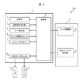
- FIG. 1 is a block diagram showing the configuration of the card processing device according to the first embodiment of the present invention
- FIG. 2 is a schematic structural diagram of the card processing device according to the same embodiment.
- the card processing apparatus 100 is mounted on, for example, an ATM (Automatic Teller Machine) installed in a financial institution.
- the card processing device 100 is configured as a card processing device that accepts a magnetic card owned by a customer, reads magnetic information recorded on the magnetic card, and receives and reads magnetic information transmitted from a terminal owned by the customer. ing.
- the card processing apparatus 100 includes a main body 1 and a shutter unit 10.
- the main body 1 includes a control unit 2, a storage unit 3, a magnetic reading unit 4, a card transport unit 5, a card position detection sensor 6, a host interface 7, and an input / output interface 20.
- a lamp 13 and a speaker 14 are connected to the input / output interface 20.
- the shutter unit 10 includes a shutter drive unit 9 and a magnetic stripe detection unit 21.
- the control unit 2 is composed of, for example, a microcomputer (CPU) and controls the operation of each unit.
- storage part 3 is comprised from memory and has memorize
- the magnetic reading unit 4 includes a magnetic head 4a and a circuit (not shown) for driving the magnetic head 4a, and the magnetic head 4a is disposed opposite to the platen roller 4b. Has been.
- the magnetic reading unit 4 reads magnetic information from the magnetic stripe of the magnetic card 200 by the magnetic head 4 a in the main body 1.
- the card transport unit 5 includes a plurality of rollers 5a and a motor or a circuit (not shown) for rotating each roller 5a.
- the card transport unit 5 sandwiches the magnetic card 200 between the rollers 5a in the main body 1 and rotates the roller 5a with the driving force of the motor to transport the magnetic card 200 back and forth.
- the card position detection sensor 6 includes a plurality of optical sensors (including a light emitting element and a light receiving element) 6a.
- the control unit 2 detects the position of the magnetic card 200 in the main body 1 based on the output state of each card position detection sensor 6.
- the host interface 7 is composed of a circuit that transmits and receives information to and from the ATM.
- the magnetic stripe detection unit 21 has, for example, a magnetic head, and outputs a signal according to an electromagnetic field change at the tip of the magnetic head. At this time, the magnetic stripe detector 21 can detect a signal by a magnetic stripe recorded on the magnetic card 200 or a signal by a radio wave transmitted from a terminal.
- the shutter drive unit 9 includes a solenoid and a circuit (not shown) for opening and closing the shutter 9a.
- a shutter unit 10 is connected to the main body 1 of the card processing apparatus 100.
- the shutter unit 10 is fixed to the opening of the plate 12 via the mounting unit 11.
- a plurality of rollers 5 a belonging to the card transport unit 5, a plurality of optical sensors 6 a belonging to the card position detection sensor 6, and a magnetic head 4 a belonging to the magnetic reading unit 4 are accommodated.
- an opening 11 a serving as an insertion / ejection port for the magnetic card 200 is formed, and a plurality of lamps 13 are fixed.
- a speaker 14 is disposed on the plate 12.
- the shutter unit 10 houses a shutter 9 a that is opened and closed by a shutter drive unit 9 and a magnetic stripe detection unit 21.
- the shutter 9a can open and close a conveyance path (card conveyance path) 200a connected to the opening 11a, and prevent foreign matter from being inserted into the conveyance path 200a in the main body 1.
- the magnetic stripe detection unit 21 is disposed in the vicinity of the conveyance path 200 a of the magnetic card 200.
- the card transport unit 5 is disposed along the transport path 200a continuous with the opening 11a, transports the magnetic card 200 inserted from the opening 11a, and the shutter drive unit 9 transports the transport path continuous with the opening 11a.
- the shutter 9a which opens and closes the conveyance path 200a between the opening 11a and the main body 1 is driven.
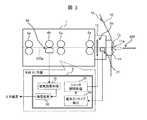
- FIG. 3 is an explanatory diagram showing a configuration in the control unit of the card processing apparatus.
- the magnetic stripe detector 21 detects the magnetic stripe of the magnetic card 200 and outputs a detection signal to the controller 2.
- the control unit 2 executes the magnetic stripe detection 2a for receiving the detection signal from the magnetic stripe detection unit 21, and executes the shutter opening / closing process 2b on condition that the detection signal is received from the magnetic stripe detection unit 21. That is, the control unit 2 executes processing for opening the shutter 9a and taking the magnetic card 200 into the main body 1 by the solenoid in the shutter drive unit 9 until the magnetic card 200 reaches the shutter 9a.
- the magnetic card 200 taken into the main body 1 is sandwiched between rollers (first rollers) 5a in the vicinity of the shutter 9a, and from the side of the first roller 5a rotated by the driving force of the motor, a roller in the vicinity of the magnetic head 4a. (Second roller) It is conveyed to the side of 5a and then passes through the magnetic head 4a.
- the control unit 2 executes a magnetic reading process 2c for reading the magnetic information written in the magnetic card 200, outputs the magnetic information written in the magnetic card 200, and via the host interface 7, A communication process 2d for transmitting magnetic information to the host apparatus (ATM) is executed.
- FIG. 4 is a time chart for explaining the operation of the magnetic stripe detector when the magnetic card is inserted.
- the magnetic card 200 inserted into the shutter unit 10 passes through the magnetic head 4a at a constant speed.
- the magnetic information is output from the magnetic head 4a at the same interval.
- the speed of the inserted magnetic card 200 is gradually increased, and the output signal of the magnetic stripe detector 21 is also gradually shortened. .
- the control unit 2 inserts the magnetic card 200 having the magnetic stripe into the shutter unit 10. It is determined that the shutter 9a is opened and the shutter 9a is opened by the solenoid in the shutter drive unit 9, and processing for taking the magnetic card 200 into the main body 1 is executed.
- FIG. 5 is a schematic configuration diagram for explaining the positional relationship between the terminal and the magnetic stripe detector in the ATM.
- the magnetic stripe detection unit 21 in the ATM 300 is disposed closer to the user 400 of the ATM 300 than the magnetic head 4 a in the main body 1.
- the magnetic head 4a in the main body 1 is far from the terminal 500 that outputs radio waves and is wireless. Since radio waves do not reach, it is difficult to receive radio waves.
- the magnetic stripe detection unit 21 is disposed near the surface of the ATM 300 and is close to the terminal 500 that outputs radio waves, so that it can easily receive magnetic information by radio waves.
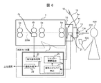
- FIG. 6 is an explanatory diagram for explaining the operation at the time of card insertion and terminal operation.
- the magnetic stripe detector 21 detects the magnetic stripe of the magnetic card 200 and outputs a detection signal to the controller 2.
- the control unit 2 executes the magnetic stripe detection 2a for receiving the detection signal from the magnetic stripe detection unit 21, executes the shutter opening / closing process 2b on the condition that the detection signal is received from the magnetic stripe detection unit 21, Until the magnetic card 200 reaches the shutter 9a, the solenoid in the shutter drive unit 9 opens the shutter 9a and executes processing for taking the magnetic card 200 into the main body 1. Thereafter, the control unit 2 executes a magnetic reading process 2c for reading the magnetic information written in the magnetic card 200, outputs the magnetic information written in the magnetic card 200, and via the host interface 7, A communication process 2d for transmitting magnetic information to the host apparatus (ATM) is executed.
- ATM host apparatus
- the magnetic stripe detector 21 receives the radio waves transmitted from the terminal 500 and receives the received radio waves. Is output to the control unit 2.
- the control unit 2 executes a magnetic reading process 2 c for reading the signal output from the magnetic stripe detection unit 21 as magnetic information, outputs the magnetic information from the terminal 500, and outputs the magnetic information from the terminal 500 via the host interface 7.
- a communication process 2d for transmitting magnetic information to (ATM) is executed.
- the control unit 2 and the magnetic reading unit 4 capture a signal detected by the magnetic stripe detection unit 21 and a signal by a radio wave or a signal by the magnetic stripe recorded on the magnetic card 200 inserted from the opening 11a.
- the control unit 2 reads the signal output from the magnetic stripe detection unit 21 as magnetic information so as not to react to the radio wave from the terminal 500. Is temporarily stopped, and the speaker 14 outputs a sound indicating that the card is being processed and does not react to the radio wave from the terminal 500, and the lamp 13 is turned on or blinked. At this time, the speaker 14 and the lamp 13 function as a notification unit that notifies that the processing for the radio wave from the terminal 500 is stopped.
- FIG. 7 is a time chart for explaining the operation when transmitting magnetic information by radio waves.
- the preamble part of the data by radio waves transmitted from the terminal 500 has a constant cycle, and the cycle does not gradually become faster. For this reason, when the cycle of the preamble portion of the signal (data) output from the magnetic stripe detector 21 is constant, the controller 2 outputs the signal output from the magnetic stripe detector 21 to the magnetic card 200. It is determined that the information is not a signal obtained from the stripe but magnetic information by radio waves transmitted from the terminal 500, the signal output from the magnetic stripe detector 21 is read as magnetic information, and the read magnetic information is read from the host interface. The data is transmitted to an external device (ATM) via the face 7.
- ATM external device
- magnetic information recorded on the magnetic card 200 or magnetic information by radio waves transmitted from the terminal 500 can be captured and processed. Further, according to the present embodiment, the magnetic information by the radio wave is not changed without adding a sensor for reading the magnetic information by the radio wave to the ATM 300 without changing the terminal 500 that transmits the radio wave.
- the shutter 9a can be opened and closed depending on the presence or absence of the magnetic stripe.
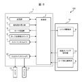
- FIG. 8 is a block diagram showing the configuration of the card processing apparatus according to the second embodiment of the present invention.
- the card insertion detection unit 8 is composed of, for example, a micro switch or an optical sensor. Since the magnetic stripe detection unit 21 and the shutter drive unit 9 have the same configuration as that of the first embodiment, description thereof is omitted.
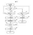
- FIG. 9 is a flowchart for explaining the operation of the card processing apparatus according to this embodiment.
- the control unit 2 monitors the output of the card insertion detection unit 8 to determine whether or not the card insertion is detected (S41), and when a positive determination result is obtained in step S41, that is, the card
- the insertion detection unit 8 detects that the magnetic card 200 is inserted into the shutter unit 10
- the control unit 2 returns to the process of step S41, and when a positive determination result is obtained in step S42, that is, the magnetic stripe detection unit 21 causes the magnetic card 200 to If a magnetic stripe is detected, card transport processing for transporting the magnetic card 200 is started (S43).
- control unit 2 executes a process for opening the shutter 9a by the solenoid in the shutter driving unit 9 and taking the magnetic card 200 into the main body 1 until the magnetic card 200 reaches the shutter 9a.
- the control unit 2 may open the shutter 9 a and take the magnetic card 200 into the main body 1 when the card insertion detection unit 8 detects the magnetic card 200.
- control unit 2 performs a magnetic information reading process for reading the magnetic information written on the magnetic card 200 by the magnetic head 4a (S44), and then monitors the output of the card position detection sensor 6. Then, it is determined whether or not the rear end of the magnetic card 200 is detected (S45). The control unit 2 continues the process of step S45 until the card position detection sensor 6 detects the rear end of the magnetic card 200. When the card position detection sensor 6 detects the rear end of the magnetic card 200, the card transport unit 5 On the other hand, a process for stopping the conveyance of the magnetic card 200 is executed (S46), and then the process in this routine is terminated.
- step S ⁇ b> 41 that is, when the card insertion detection unit 8 does not detect that the magnetic card 200 is inserted into the shutter unit 10, the control unit 2 starts from the terminal 500. Then, it is determined whether or not magnetic data by radio waves has been received (S47). When a negative determination result is obtained in step S47, the control unit 2 returns to the process of step S41, and when a positive determination result is obtained in step S47, that is, when the magnetic stripe detection unit 21 receives a radio wave from the terminal 500. When magnetic data (magnetic information) is received, a magnetic information reading process for reading the magnetic information from the output signal of the magnetic stripe detector 21 is executed (S48), and then the process in this routine is terminated.
- magnetic data magnetic information
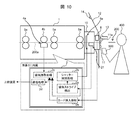
- FIG. 10 is an explanatory diagram for explaining operations at the time of card insertion and terminal operation.
- the card insertion detection unit 8 detects the magnetic card 200 inserted from the opening 11 a of the mounting unit 11, the card insertion is performed.
- a detection signal is output from the detection unit 8 to the control unit 2.
- the control unit 2 performs the card insertion detection 2e immediately in response to the detection signal from the card insertion detection unit 8.
- a detection signal is output from the magnetic stripe detection unit 21 to the control unit 2.
- the control unit 2 executes the magnetic stripe detection 2a, and executes the shutter opening / closing process 2b on the condition that the detection signal is received from the magnetic stripe detection unit 21, Until the magnetic card 200 reaches the shutter 9a, the solenoid in the shutter drive unit 9 opens the shutter 9a and executes processing for taking the magnetic card 200 into the main body 1. Thereafter, the control unit 2 executes a magnetic reading process 2c for reading the magnetic information written in the magnetic card 200, outputs the magnetic information written in the magnetic card 200, and via the host interface 7, A communication process 2d for transmitting magnetic information to the host apparatus (ATM) is executed.
- ATM host apparatus
- the magnetic stripe detector 21 receives the radio waves transmitted from the terminal 500 and receives the received radio waves. Is output to the control unit 2. At this time, since the control unit 2 does not receive the detection signal from the card insertion detection unit 8, the control unit 2 determines that the signal output from the magnetic stripe detection unit 21 is the magnetic information obtained from the radio wave, and the magnetic stripe. In order to execute the magnetic reading process 2c for reading the signal output from the detection unit 21, to output the magnetic information from the terminal 500, and to transmit the magnetic information to the host device (ATM) via the host interface 7. The communication process 2d is executed.
- FIG. 11 is a time chart for explaining the operation of the magnetic stripe detector and the card insertion detector when the magnetic card is inserted.
- the card insertion detection unit 8 detects the magnetic card 200 at time t 1
- the card insertion detection unit 8 indicates “card present” to the control unit 2.
- a detection signal is output.
- the magnetic stripe detection unit 21 sends a signal based on the magnetic information of the preamble portion recorded near the tip of the magnetic stripe of the magnetic card 200 to the control unit 2. Is output.
- the control unit 2 determines that the output signal of the magnetic stripe detection unit 21 is magnetic information by the magnetic stripe.
- a process for opening the shutter 9a and taking the magnetic card 200 into the main body 1 is executed by the solenoid in the shutter drive unit 9.
- FIG. 12 is a time chart for explaining the operation when reading magnetic information by radio waves.
- the preamble portion of the data by radio waves transmitted from the terminal 500 has a fixed period
- the magnetic stripe detector 21 receives the data of the preamble portion from the data by radio waves from the terminal 500, the magnetic stripe A signal with a constant period is output from the detector 21.
- the card insertion detection unit 8 outputs a signal indicating “no card”.
- control unit 2 determines that the signal (data) output from the magnetic stripe detection unit 21 is a radio wave signal, and the magnetic stripe
- the signal output from the detection unit 21 is read as magnetic information, and the read magnetic information is transmitted to an external device (ATM) via the host interface 7.
- the card insertion detection unit 8 can immediately detect that the magnetic card 200 has been inserted.
- the card insertion detection unit 8 does not detect the magnetic card 200, it can be immediately determined that the signal detected by the magnetic stripe detection unit 21 is magnetic information by radio waves transmitted from the terminal 500.
- the card processing apparatus 100 in the above-described embodiment can be applied to an automatic transaction apparatus.
- an input / output unit touchscreen for inputting and outputting information
- a card processing unit card reader
- recording and processing information on a receipt When configuring an automatic transaction apparatus including a receipt processing unit, a cash processing unit that inputs and outputs cash (including banknotes and coins), and a control unit that performs overall control and transmits and receives information to and from a database.
- the components of the card processing apparatus 100 can be mounted on the card processing unit.
- each of the above-described configurations, functions, etc. may be realized by hardware by designing a part or all of them, for example, by an integrated circuit.
- Each of the above-described configurations, functions, and the like may be realized by software by interpreting and executing a program that realizes each function by the processor.
- Information such as programs, tables, and files that realize each function should be recorded in a recording device such as a memory, hard disk, SSD (Solid State Drive), or a recording medium such as an IC card, SD card, or DVD. Can do.
Landscapes
- Engineering & Computer Science (AREA)
- General Physics & Mathematics (AREA)
- Physics & Mathematics (AREA)
- Theoretical Computer Science (AREA)
- Business, Economics & Management (AREA)
- Accounting & Taxation (AREA)
- Strategic Management (AREA)
- General Business, Economics & Management (AREA)
- Computer Vision & Pattern Recognition (AREA)
- Artificial Intelligence (AREA)
- Microelectronics & Electronic Packaging (AREA)
- Computer Networks & Wireless Communication (AREA)
- Control Of Vending Devices And Auxiliary Devices For Vending Devices (AREA)
- Conveying Record Carriers (AREA)
Abstract
Description
(1-1)カード処理装置の構成
まず、本実施の形態にかかるカード処理装置100の構成について、図1および図2を参照して説明する。図1は、本発明の第1の実施の形態に係るカード処理装置の構成を示すブロック図であり、図2は、同実施の形態にかかるカード処理装置の概略構造図である。
図3は、カード処理装置の制御部内の構成を示す説明図である。図3において、シャッタユニット10に挿入された磁気カード200に磁気情報が書き込まれている場合、取付ユニット11の開口部11aから挿入された磁気カード200のうち磁気ストライプの部位が磁気ストライプ検知部21の位置に到達すると、磁気ストライプ検知部21は、磁気カード200の磁気ストライプを検知して検知信号を制御部2に出力する。制御部2は、磁気ストライプ検知部21から検知信号を受信するための磁気ストライプ検出2aを実行し、磁気ストライプ検知部21から検知信号を受信したことを条件に、シャッタ開閉処理2bを実行する。即ち、制御部2は、磁気カード200がシャッタ9aに到達するまでに、シャッタ駆動部9内のソレノイドにより、シャッタ9aを開け、磁気カード200を本体1に取り込むための処理を実行する。
図5は、端末とATM内の磁気ストライプ検知部との位置関係を説明するための概略構成図である。図5において、ATM300内の磁気ストライプ検知部21は、本体1内の磁気ヘッド4aと比較して、ATM300の利用者400に近い位置に配置される。
(2-1)カード処理装置の構成
次に、第2の実施の形態について説明する。本実施の形態にかかるカード処理装置100の構成における、第1の実施の形態と同様箇所については詳細な説明は省略し、以下では、第1の実施の形態と異なるカード挿入検知センサに係わる構成および動作について詳細に説明する。図8は、本発明の第2の実施の形態にかかるカード処理装置の構成を示すブロック図である。
第2の実施の形態における、磁気カード挿入による磁気情報の読取り、もしくは、無線電波により磁気情報を受信し、磁気情報を読取る場合の動作を図9に従って説明する。図9は、本実施の形態かかるカード処理装置の動作を説明するためのフローチャートである。
図10は、カード挿入時と端末操作時の動作を説明するための説明図である。図10において、シャッタユニット10に挿入された磁気カード200に磁気情報が書き込まれている場合、カード挿入検知部8が取付ユニット11の開口部11aから挿入された磁気カード200を検知すると、カード挿入検知部8から制御部2に検知信号が出力される。制御部2は、カード挿入検知部8からの検知信号に応答して即座にカード挿入検知2eを行う。続いて、磁気ストライプ検知部21が、磁気カード200の磁気ストライプを検知すると、磁気ストライプ検知部21から制御部2に検知信号が出力される。制御部2は、磁気ストライプ検知部21から検知信号を受信した場合、磁気ストライプ検出2aを実行し、磁気ストライプ検知部21から検知信号を受信したことを条件に、シャッタ開閉処理2bを実行し、磁気カード200がシャッタ9aに到達するまでに、シャッタ駆動部9内のソレノイドにより、シャッタ9aを開け、磁気カード200を本体1に取り込むための処理を実行する。この後、制御部2は、磁気カード200に書き込まれた磁気情報を読み取るための磁気読取処理2cを実行し、磁気カード200に書き込まれた磁気情報を出力し、ホストインタフェイス7を介して、上位装置(ATM)に磁気情報を送信するための通信処理2dを実行する。
Claims (8)
- 磁気カードの挿入排出口となる開口部と、
前記開口部近傍に配置され、電磁界の変化を検知して信号を出力する磁気ストライプ検知部と、
磁気情報を読み取る磁気情報読み取り部と、
前記開口部に連なる搬送路に沿って配置され、前記開口部から挿入された前記磁気カードを搬送するカード搬送部と、
前記開口部に連なる搬送路を開閉するシャッタを駆動するシャッタ駆動部と、
を備え、
前記磁気ストライプ検知部は、
前記開口部から挿入された前記磁気カードに記録された磁気ストライプによる信号を検知する、又は前記開口部近傍に配置される端末から送信される前記無線電波による信号を検知し前記無線電波で送信された磁気情報を読み取る磁気情報処理部を備えた
ことを特徴とする、カード処理装置。 - 前記磁気情報処理部は、
前記磁気ストライプ検知部の検知による信号の周期により、前記磁気カードに記録された磁気ストライプの磁気情報か、前記端末から前記無線電波で送信された磁気情報かを判定する
ことを特徴とする、請求項1に記載のカード処理装置。 - 前記シャッタ駆動部は、
前記磁気ストライプ検知部が、前記開口部から挿入された前記磁気カードに記録された磁気ストライプによる信号を検知したことを条件に、前記シャッタを開く処理を実行する
ことを特徴とする、請求項2に記載のカード処理装置。 - 前記磁気情報処理部は、
前記開口部から挿入された前記磁気カードに記録された磁気ストライプによる信号を取り込んで磁気情報として処理する場合、当該処理中は、前記磁気ストライプ検知部から前記無線電波による信号が出力されても、当該信号に対する処理を停止する
ことを特徴とする、請求項3に記載のカード処理装置。 - 前記磁気情報処理部が、前記磁気カードに記録された磁気ストライプによる信号を読み取って磁気情報として処理する場合、前記端末からの無線電波に対する処理を停止する旨を報知する報知部を更に備える
ことを特徴とする、請求項4に記載のカード処理装置。 - 前記開口部から挿入された前記磁気カードを検知するカード挿入検知部を更に備え、
前記磁気情報処理部は、
前記カード挿入検知部が前記磁気カードを検知したことを条件に、処理対象となる磁気情報を、前記磁気カードに記録された磁気ストライプの磁気情報と判定し、前記カード挿入検知部が前記磁気カードを検知しないことを条件に、前記処理対象となる磁気情報を、前記無線電波で送信された磁気情報と判定する
ことを特徴とする、請求項1に記載のカード処理装置。 - 前記シャッタ駆動部は、
前記カード挿入検知部が、前記開口部から挿入された前記磁気カードを検知したことを条件に、前記シャッタを開く処理を実行する
ことを特徴とする、請求項6に記載のカード処理装置。 - 情報の入出力を行う入出力部と、磁気カードに記録された磁気情報を読み取って処理するカード処理部と、現金の入出力を行う現金処理部と、全体を統括制御する制御部とを備えた自動取引装置であって、
前記カード処理部に、請求項1~7のうちいずれか1項に記載のカード処理装置の構成要素を搭載する
ことを特徴とする、自動取引装置。
Priority Applications (3)
| Application Number | Priority Date | Filing Date | Title |
|---|---|---|---|
| JP2018520339A JP6602974B2 (ja) | 2016-05-30 | 2016-11-16 | カード処理装置および自動取引装置 |
| KR1020187015631A KR102009700B1 (ko) | 2016-05-30 | 2016-11-16 | 카드 처리 장치 및 자동 거래 장치 |
| CN201680075653.3A CN108431822B (zh) | 2016-05-30 | 2016-11-16 | 卡处理装置以及自动交易装置 |
Applications Claiming Priority (2)
| Application Number | Priority Date | Filing Date | Title |
|---|---|---|---|
| JP2016107987 | 2016-05-30 | ||
| JP2016-107987 | 2016-05-30 |
Publications (1)
| Publication Number | Publication Date |
|---|---|
| WO2017208479A1 true WO2017208479A1 (ja) | 2017-12-07 |
Family
ID=60479471
Family Applications (1)
| Application Number | Title | Priority Date | Filing Date |
|---|---|---|---|
| PCT/JP2016/083958 Ceased WO2017208479A1 (ja) | 2016-05-30 | 2016-11-16 | カード処理装置および自動取引装置 |
Country Status (4)
| Country | Link |
|---|---|
| JP (1) | JP6602974B2 (ja) |
| KR (1) | KR102009700B1 (ja) |
| CN (1) | CN108431822B (ja) |
| WO (1) | WO2017208479A1 (ja) |
Citations (3)
| Publication number | Priority date | Publication date | Assignee | Title |
|---|---|---|---|---|
| JP2005044107A (ja) * | 2003-07-28 | 2005-02-17 | Omron Corp | 磁気カード処理装置 |
| US20110006112A1 (en) * | 2008-03-03 | 2011-01-13 | Wincor Nixdorf International Gmbh | Protective device and method for preventing skimming on a card reader |
| US8814046B1 (en) * | 2013-03-14 | 2014-08-26 | Looppay Inc | System and method for a baseband nearfield magnetic stripe data transmitter |
Family Cites Families (6)
| Publication number | Priority date | Publication date | Assignee | Title |
|---|---|---|---|---|
| JP2002304643A (ja) | 2001-04-06 | 2002-10-18 | Toshiba Corp | 多種媒体取扱い装置とカード処理装置 |
| JP2003108948A (ja) | 2001-09-28 | 2003-04-11 | Toshiba Corp | カード処理装置 |
| EP2584498A1 (en) * | 2009-11-09 | 2013-04-24 | Hitachi-Omron Terminal Solutions, Corp. | Card processing apparatus |
| US8763898B2 (en) * | 2010-03-02 | 2014-07-01 | First Data Corporation | Advanced card merge machine |
| JP5807123B2 (ja) * | 2012-09-05 | 2015-11-10 | 日立オムロンターミナルソリューションズ株式会社 | 磁気記録媒体読取装置 |
| US20150097029A1 (en) * | 2013-10-09 | 2015-04-09 | Castles Technology Co., Ltd. | Transactional Device Having Element for Identifying Wireless Sensing |
-
2016
- 2016-11-16 KR KR1020187015631A patent/KR102009700B1/ko active Active
- 2016-11-16 CN CN201680075653.3A patent/CN108431822B/zh active Active
- 2016-11-16 JP JP2018520339A patent/JP6602974B2/ja active Active
- 2016-11-16 WO PCT/JP2016/083958 patent/WO2017208479A1/ja not_active Ceased
Patent Citations (3)
| Publication number | Priority date | Publication date | Assignee | Title |
|---|---|---|---|---|
| JP2005044107A (ja) * | 2003-07-28 | 2005-02-17 | Omron Corp | 磁気カード処理装置 |
| US20110006112A1 (en) * | 2008-03-03 | 2011-01-13 | Wincor Nixdorf International Gmbh | Protective device and method for preventing skimming on a card reader |
| US8814046B1 (en) * | 2013-03-14 | 2014-08-26 | Looppay Inc | System and method for a baseband nearfield magnetic stripe data transmitter |
Also Published As
| Publication number | Publication date |
|---|---|
| JP6602974B2 (ja) | 2019-11-06 |
| CN108431822B (zh) | 2021-04-09 |
| KR102009700B1 (ko) | 2019-08-13 |
| JPWO2017208479A1 (ja) | 2018-11-01 |
| CN108431822A (zh) | 2018-08-21 |
| KR20180080282A (ko) | 2018-07-11 |
Similar Documents
| Publication | Publication Date | Title |
|---|---|---|
| JP4680048B2 (ja) | カード処理装置 | |
| CA2621850C (en) | Automated banking machine anti-skimming card reader | |
| JP5648173B2 (ja) | カードリーダ及びその処理方法 | |
| CN102654929B (zh) | 自动交易装置 | |
| JPWO2013030875A1 (ja) | 磁気記録媒体読取装置 | |
| JP2018180754A (ja) | カード処理装置および自動取引機 | |
| JP6602974B2 (ja) | カード処理装置および自動取引装置 | |
| JP2022097304A (ja) | 冊子類搬送装置、冊子類搬送方法及び冊子類搬送プログラム | |
| JP5049681B2 (ja) | カード読取装置 | |
| US12548003B2 (en) | Apparatus and method for facilitating NFC transactions within payment slot | |
| JP5494765B2 (ja) | 自動取引装置 | |
| JP5421897B2 (ja) | カードリーダ及びカードリーダにおける情報通信方法 | |
| WO2016009697A1 (ja) | 自動取引装置 | |
| JP6820786B2 (ja) | カード処理装置、自動取引装置 | |
| JP6492984B2 (ja) | 自動取引装置 | |
| KR20190032131A (ko) | 금융 자동화 기기 및 그 제어방법 | |
| JP6026975B2 (ja) | 自動取引装置およびその制御プログラム | |
| KR20060077496A (ko) | 금융 자동화 기기의 카세트 공검지 시스템 및 방법 | |
| JP2017045118A (ja) | 自動取引装置 | |
| JPH02300040A (ja) | 媒体搬送装置 | |
| WO2016061084A1 (en) | Can bus security | |
| JP2013168105A (ja) | シャッタ制御装置、方法、及び、プログラム | |
| KR20130128206A (ko) | 매체감지장치 및 이를 이용한 금융기기 |
Legal Events
| Date | Code | Title | Description |
|---|---|---|---|
| ENP | Entry into the national phase |
Ref document number: 20187015631 Country of ref document: KR Kind code of ref document: A |
|
| ENP | Entry into the national phase |
Ref document number: 2018520339 Country of ref document: JP Kind code of ref document: A |
|
| 121 | Ep: the epo has been informed by wipo that ep was designated in this application |
Ref document number: 16904103 Country of ref document: EP Kind code of ref document: A1 |
|
| NENP | Non-entry into the national phase |
Ref country code: DE |
|
| 122 | Ep: pct application non-entry in european phase |
Ref document number: 16904103 Country of ref document: EP Kind code of ref document: A1 |