WO2017204329A1 - ディスクブレーキおよびピストンブーツ - Google Patents
ディスクブレーキおよびピストンブーツ Download PDFInfo
- Publication number
- WO2017204329A1 WO2017204329A1 PCT/JP2017/019693 JP2017019693W WO2017204329A1 WO 2017204329 A1 WO2017204329 A1 WO 2017204329A1 JP 2017019693 W JP2017019693 W JP 2017019693W WO 2017204329 A1 WO2017204329 A1 WO 2017204329A1
- Authority
- WO
- WIPO (PCT)
- Prior art keywords
- piston
- metal member
- peripheral surface
- inner peripheral
- annular
- Prior art date
- Legal status (The legal status is an assumption and is not a legal conclusion. Google has not performed a legal analysis and makes no representation as to the accuracy of the status listed.)
- Ceased
Links
Images


Classifications
-
- B—PERFORMING OPERATIONS; TRANSPORTING
- B29—WORKING OF PLASTICS; WORKING OF SUBSTANCES IN A PLASTIC STATE IN GENERAL
- B29C—SHAPING OR JOINING OF PLASTICS; SHAPING OF MATERIAL IN A PLASTIC STATE, NOT OTHERWISE PROVIDED FOR; AFTER-TREATMENT OF THE SHAPED PRODUCTS, e.g. REPAIRING
- B29C45/00—Injection moulding, i.e. forcing the required volume of moulding material through a nozzle into a closed mould; Apparatus therefor
- B29C45/14—Injection moulding, i.e. forcing the required volume of moulding material through a nozzle into a closed mould; Apparatus therefor incorporating preformed parts or layers, e.g. injection moulding around inserts or for coating articles
-
- F—MECHANICAL ENGINEERING; LIGHTING; HEATING; WEAPONS; BLASTING
- F16—ENGINEERING ELEMENTS AND UNITS; GENERAL MEASURES FOR PRODUCING AND MAINTAINING EFFECTIVE FUNCTIONING OF MACHINES OR INSTALLATIONS; THERMAL INSULATION IN GENERAL
- F16J—PISTONS; CYLINDERS; SEALINGS
- F16J15/00—Sealings
- F16J15/50—Sealings between relatively-movable members, by means of a sealing without relatively-moving surfaces, e.g. fluid-tight sealings for transmitting motion through a wall
- F16J15/52—Sealings between relatively-movable members, by means of a sealing without relatively-moving surfaces, e.g. fluid-tight sealings for transmitting motion through a wall by means of sealing bellows or diaphragms
-
- F—MECHANICAL ENGINEERING; LIGHTING; HEATING; WEAPONS; BLASTING
- F16—ENGINEERING ELEMENTS AND UNITS; GENERAL MEASURES FOR PRODUCING AND MAINTAINING EFFECTIVE FUNCTIONING OF MACHINES OR INSTALLATIONS; THERMAL INSULATION IN GENERAL
- F16D—COUPLINGS FOR TRANSMITTING ROTATION; CLUTCHES; BRAKES
- F16D65/00—Parts or details
- F16D65/14—Actuating mechanisms for brakes; Means for initiating operation at a predetermined position
- F16D65/16—Actuating mechanisms for brakes; Means for initiating operation at a predetermined position arranged in or on the brake
- F16D65/18—Actuating mechanisms for brakes; Means for initiating operation at a predetermined position arranged in or on the brake adapted for drawing members together, e.g. for disc brakes
-
- F—MECHANICAL ENGINEERING; LIGHTING; HEATING; WEAPONS; BLASTING
- F16—ENGINEERING ELEMENTS AND UNITS; GENERAL MEASURES FOR PRODUCING AND MAINTAINING EFFECTIVE FUNCTIONING OF MACHINES OR INSTALLATIONS; THERMAL INSULATION IN GENERAL
- F16J—PISTONS; CYLINDERS; SEALINGS
- F16J3/00—Diaphragms; Bellows; Bellows pistons
- F16J3/04—Bellows
- F16J3/041—Non-metallic bellows
- F16J3/042—Fastening details
-
- B—PERFORMING OPERATIONS; TRANSPORTING
- B60—VEHICLES IN GENERAL
- B60T—VEHICLE BRAKE CONTROL SYSTEMS OR PARTS THEREOF; BRAKE CONTROL SYSTEMS OR PARTS THEREOF, IN GENERAL; ARRANGEMENT OF BRAKING ELEMENTS ON VEHICLES IN GENERAL; PORTABLE DEVICES FOR PREVENTING UNWANTED MOVEMENT OF VEHICLES; VEHICLE MODIFICATIONS TO FACILITATE COOLING OF BRAKES
- B60T1/00—Arrangements of braking elements, i.e. of those parts where braking effect occurs specially for vehicles
- B60T1/02—Arrangements of braking elements, i.e. of those parts where braking effect occurs specially for vehicles acting by retarding wheels
- B60T1/06—Arrangements of braking elements, i.e. of those parts where braking effect occurs specially for vehicles acting by retarding wheels acting otherwise than on tread, e.g. employing rim, drum, disc, or transmission or on double wheels
- B60T1/065—Arrangements of braking elements, i.e. of those parts where braking effect occurs specially for vehicles acting by retarding wheels acting otherwise than on tread, e.g. employing rim, drum, disc, or transmission or on double wheels employing disc
-
- F—MECHANICAL ENGINEERING; LIGHTING; HEATING; WEAPONS; BLASTING
- F16—ENGINEERING ELEMENTS AND UNITS; GENERAL MEASURES FOR PRODUCING AND MAINTAINING EFFECTIVE FUNCTIONING OF MACHINES OR INSTALLATIONS; THERMAL INSULATION IN GENERAL
- F16D—COUPLINGS FOR TRANSMITTING ROTATION; CLUTCHES; BRAKES
- F16D65/00—Parts or details
- F16D65/78—Features relating to cooling
- F16D2065/785—Heat insulation or reflection
-
- F—MECHANICAL ENGINEERING; LIGHTING; HEATING; WEAPONS; BLASTING
- F16—ENGINEERING ELEMENTS AND UNITS; GENERAL MEASURES FOR PRODUCING AND MAINTAINING EFFECTIVE FUNCTIONING OF MACHINES OR INSTALLATIONS; THERMAL INSULATION IN GENERAL
- F16D—COUPLINGS FOR TRANSMITTING ROTATION; CLUTCHES; BRAKES
- F16D2121/00—Type of actuator operation force
- F16D2121/02—Fluid pressure
-
- F—MECHANICAL ENGINEERING; LIGHTING; HEATING; WEAPONS; BLASTING
- F16—ENGINEERING ELEMENTS AND UNITS; GENERAL MEASURES FOR PRODUCING AND MAINTAINING EFFECTIVE FUNCTIONING OF MACHINES OR INSTALLATIONS; THERMAL INSULATION IN GENERAL
- F16D—COUPLINGS FOR TRANSMITTING ROTATION; CLUTCHES; BRAKES
- F16D2125/00—Components of actuators
- F16D2125/02—Fluid-pressure mechanisms
- F16D2125/06—Pistons
Definitions
- the present invention relates to a disc brake and a piston boot.
- This application claims priority based on Japanese Patent Application No. 2016-106416 filed in Japan on May 27, 2016, the contents of which are incorporated herein by reference.
- a disc brake may have a configuration using a piston boot having a structure in which an annular metal member is embedded in an elastic body as a piston boot mounted between a piston and a cylinder (see, for example, Patent Document 1).
- the piston boot with the above structure has a problem in productivity, and may cause an increase in the cost of the disc brake.
- the present invention provides a disc brake and a piston boot that can suppress an increase in cost.
- the disc brake includes a piston that presses at least one of a pair of pads opposed to both sides of the disc, and the piston is movably accommodated, with one end opened.
- a cylinder having a bore portion from which the tip of the piston protrudes, and a step portion having an inner diameter larger than the inner diameter of the bore portion formed on the opening side of the bore portion;
- a piston boot having a bellows part that can be expanded and contracted with movement of the piston, and the piston boot is formed on one end side of the bellows part and includes an annular metal member.
- An annular fitting part that fits into the step part, and the fitting part has an outer peripheral surface part that comes into contact with the inner peripheral surface of the step part and an annular contact part that comes into contact with the annular wall surface part of the step part.
- a plane portion, and the plane The plurality of holes having a bottom surface in the vicinity of the position or the metal member of the metal member is open, respectively.
- the fitting portion has a plurality of openings formed in the disk radial direction inwardly in the disk radial direction from the metal member and formed along the disk axial direction.
- a notch may be provided.
- the radially outward position of the notch portion may be the position of the inner peripheral surface of the metal member or the vicinity of the inner peripheral surface of the metal member.
- the plurality of holes and the notch portion may be formed at different positions in the circumferential direction of the fitting portion.
- the piston boot is disposed between the front end side of the piston provided in the caliper of the disc brake and a step portion formed in the cylinder opening of the caliper, and the movement of the piston
- a piston boot having a bellows part that can be expanded and contracted, wherein the piston boot is formed on one end side of the bellows part and includes an annular metal member and is fitted into the step part.
- the fitting portion has an outer peripheral surface portion that contacts the inner peripheral surface of the step portion, and an annular flat surface portion that contacts the annular wall surface portion of the step portion.
- a plurality of holes having bottom surfaces are opened at positions of the metal member or in the vicinity of the metal member.
- the fitting portion opens on the inner circumferential surface of the fitting portion between the inner circumferential surface of the fitting portion and the metal member, and is radially outward. You may provide the notch part dented towards.
- the radially outward position of the notch may be the position of the inner peripheral surface of the metal member or a position near the inner peripheral surface of the metal member.
- the plurality of holes and the notch portion may be formed at different positions in the circumferential direction of the fitting portion.
- the above-described disc brake and piston boot can suppress an increase in cost.
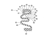
- FIG. 4 is a cross-sectional view taken along line AA in FIG. 3.
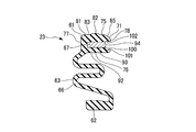
- FIG. 4 is a sectional view taken along line BB in FIG. 3.
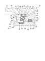
- FIG. 1 is a view showing a disc brake 10.
- the disc brake 10 is for vehicles such as automobiles, and specifically for four-wheeled vehicles.
- the disc brake 10 brakes the vehicle by stopping the rotation of the disc 11 that rotates with a wheel (not shown).
- the disc brake 10 includes a support member 12, a pair of pads 13 and 14, and a caliper 15.
- the support member 12 is disposed across the outer peripheral side of the disk 11.
- the support member 12 is fixed to the non-rotating part of the vehicle.
- the pair of pads 13 and 14 are supported by the support member 12 so as to be movable in the axial direction of the disk 11.
- the pair of pads 13 and 14 are disposed on both sides of the disk 11 so as to face each other.
- the caliper 15 is supported by the support member 12 so as to be movable in the axial direction of the disk 11.
- the caliper 15 sandwiches the pair of pads 13 and 14 and presses them against both sides of the disk 11.
- the caliper 15 has a caliper body 20, a piston 21, a piston seal 22, and a piston boot 23.
- the caliper body 20 includes a cylinder 26, a bridge portion 27 that extends from the cylinder 26 so as to straddle the outer periphery of the disk 11, and a claw portion 28 that extends from the opposite side of the bridge 26 to the cylinder 26 and faces the cylinder 26. And have.
- the cylinder 26 is formed with a bore portion 30 having one end opened on the claw portion 28 side.
- the bore portion 30 accommodates the piston 21 so as to be movable in the axial direction of the disk 11.
- the cylinder 26 has a bottom portion 31 opposite to the claw portion 28 and a cylindrical portion 32 that extends from the outer peripheral edge of the bottom portion 31 to the claw portion 28 side. And have.
- a through hole 33 for introducing brake fluid into the bore 30 is formed in the bottom 31 of the cylinder 26.
- the bore portion 30 has a guide inner peripheral surface 35 that is a cylindrical surface that guides the movement of the piston 21.
- the bore portion 30 has an annular large-diameter groove 36 closer to the bottom portion 31 than the guide inner peripheral surface 35.
- the large diameter groove 36 has a shape that is recessed outward in the radial direction from the guide inner peripheral surface 35.
- the bore portion 30 has an annular piston seal groove 37 at an intermediate position opposite to the bottom portion 31 of the guide inner peripheral surface 35.
- the piston seal groove 37 has a shape that is recessed radially outward from the guide inner peripheral surface 35.
- the piston seal groove 37 has an inner diameter larger than the inner diameter of the guide inner peripheral surface 35.
- an annular step portion 41 is formed on the claw portion 28 side which is the opening side of the bore portion 30.
- the step portion 41 has a shape that is recessed radially outward from the guide inner peripheral surface 35 of the bore portion 30.
- the step portion 41 has a step shape that extends to the claw portion 28 side, and is formed at the opening position of the cylinder 26.
- the step portion 41 has an inner diameter larger than the inner diameter of the guide inner peripheral surface 35 of the bore portion 30 and larger than the inner diameters of the piston seal groove 37 and the large diameter groove 36. In other words, the inner diameter of the step portion 41 is larger than the inner diameter at any position of the bore portion 30.
- the step portion 41 has a cylindrical inner peripheral surface 42 shown in FIG. 2 centering on the central axis of the bore portion 30, and the bore portion 30 side in the axial direction of the inner peripheral surface 42. It has a planar annular wall surface portion 43 that is orthogonal.
- an annular engagement groove 46 that is recessed radially outward from the main inner peripheral surface 45 made of a cylindrical surface of the inner peripheral surface 42 at an intermediate position on the annular wall surface 43 side of the inner peripheral surface 42. Is formed.
- the inner peripheral surface 42 of the step portion 41 is composed of a main inner peripheral surface 45 and an inner surface of the engaging groove 46.
- the annular wall surface portion 43 is a flat surface orthogonal to the central axis of the bore portion 30 and has an annular shape centering on the central axis of the bore portion 30.
- the piston 21 includes a bottom portion 51 and a cylindrical portion 52.
- the piston 21 is formed in a bottomed cylindrical shape in which an end portion opposite to the bottom portion 51 of the cylindrical portion 52 is an opening 53.
- An annular locking groove 55 is formed on the opening 53 side of the cylindrical portion 52.
- the locking groove 55 has a shape that is recessed radially inward from the outer diameter surface 54 formed of the cylindrical surface of the cylindrical portion 52.
- the piston 21 is accommodated in the bore portion 30 such that the bottom portion 51 is positioned on the bottom portion 31 side in the bore portion 30.
- the tip on the claw portion 28 side that is, the opening 53 side protrudes toward the claw portion 28 side from the bore portion 30.
- a locking groove 55 is formed in the piston 21 on the tip side protruding from the bore portion 30. That is, the locking groove 55 is disposed outside the bore portion 30.
- the piston seal 22 is fitted in the piston seal groove 37 of the bore portion 30.
- the piston 21 is fitted on the inner peripheral side of the piston seal 22.
- the piston seal 22 seals the gap between the cylinder 26 and the piston 21, and supports the piston 21 so as to be movable in the axial direction with the guide inner peripheral surface 35 of the bore portion 30.
- the piston boot 23 is disposed between a locking groove 55 on the tip side of the piston 21 provided in the caliper 15 and a step portion 41 formed at the opening position of the cylinder 26 of the caliper 15.
- the piston boot 23 is engaged with the locking groove 55 and the step portion 41, respectively.
- the piston boot 23 covers the outer peripheral portion exposed from the cylinder 26 at a portion closer to the bore portion 30 than the locking groove 55 of the piston 21.
- the piston boot 23 includes an annular large-diameter fitting portion 61 (fitting portion) that fits into the step portion 41 of the cylinder 26, an annular small-diameter fitting portion 62 that fits into the locking groove 55 of the piston 21, A bellows portion 63 that can be expanded and contracted is provided.
- the large diameter fitting portion 61 is formed on one end side of the bellows portion 63
- the small diameter fitting portion 62 is formed on the other end side of the bellows portion 63.
- the piston boot 23 has a large-diameter fitting portion 61 formed on one end side, a small-diameter fitting portion 62 formed on the other end side, and a bellows portion 63 formed on the intermediate portion.
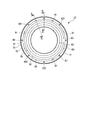
- the large-diameter fitting part 61 and the small-diameter fitting part 62 are both annular as shown in FIG. As shown in FIG. 2, the small diameter fitting portion 62 has a smaller inner diameter than the large diameter fitting portion 61.
- the small-diameter fitting portion 62 is fitted in the locking groove 55 of the piston 21 at the inner peripheral portion.
- the outer diameter of the large-diameter fitting portion 61 is fitted to the step portion 41 of the cylinder 26.
- the piston boot 23 has a large-diameter fitting portion 61 fixed to the cylinder 26.
- the piston boot 23 in which the small-diameter fitting portion 62 is fixed to the piston 21 has an intermediate bellows portion 63 that is not fixed to the cylinder 26 and the piston 21 as the piston 21 moves relative to the cylinder 26. It expands and contracts.
- the piston boot 23 is configured by embedding an annular metal member 67 inside a rubber annular elastic member 66.
- the metal member 67 has higher rigidity than the elastic member 66 and is less likely to deform than the elastic member 66.
- the metal member 67 is a cylindrical body whose axial length is longer than its radial thickness.
- the metal member 67 is included in the large-diameter fitting portion 61 described above.
- the large-diameter fitting portion 61 is formed in a cylindrical shape by the entire metal member 67 and the elastic member constituting portion 71 that is a part of the elastic member 66.
- the bellows portion 63 is formed of an elastic member 66 only and has a bellows shape.
- the small diameter fitting portion 62 is formed in a cylindrical shape by only the elastic member 66.
- the metal member 67 is a cylindrical body as described above, but may be a polygonal cylindrical body.
- the elastic member constituting portion 71 of the large-diameter fitting portion 61 constitutes an outer portion of the large-diameter fitting portion 61 and has an annular shape.
- a metal member 67 is disposed inside the elastic member constituting portion 71 in the radial direction and inside the axial direction.
- the elastic member constituting portion 71 and the metal member 67 are not bonded, but they may be bonded and integrated.
- the elastic member constituting portion 71 covers both the inner diameter side and the outer diameter side of the cylindrical metal member 67 and also covers both sides of the metal member 67 in the axial direction.
- the annular large-diameter fitting portion 61 includes an outer peripheral surface portion 75, an inner peripheral surface portion 76, a flat portion 77 at one end in the axial direction, and a flat portion 78 at the other end in the axial direction.
- the outer peripheral surface portion 75 and the inner peripheral surface portion 76 are cylindrical.
- the outer peripheral surface portion 75 and the inner peripheral surface portion 76 are arranged coaxially.
- the flat portions 77 and 78 are both flat surfaces that are orthogonal to the central axis of the large-diameter fitting portion 61. All of the outer peripheral surface portion 75, the flat surface portion 77, and the flat surface portion 78 of the large-diameter fitting portion 61 are the elastic member constituting portion 71.
- One end side of the bellows portion 63 extends from an end edge portion of the inner peripheral surface portion 76 that is the elastic member constituting portion 71 on the flat portion 77 side.
- the other end side of the bellows portion 63 is connected to an end edge portion on one axial side of the inner peripheral surface of the small diameter fitting portion 62.
- the connecting side of the bellows part 63 in the small diameter fitting part 62 and the connecting side of the bellows part 63 in the large diameter fitting part 61 are opposite to each other in the axial direction of the piston boot 23.
- the elastic member constituting portion 71 of the large-diameter fitting portion 61 includes a base portion 81 and an annular projecting portion 82 that protrudes radially outward from the base portion 81 from the axial center position of the base portion 81. .
- the entire outer peripheral surface portion 75 of the large-diameter fitting portion 61 is an elastic member constituting portion 71.
- the outer peripheral surface portion 75 includes a main outer peripheral surface 83 that is a cylindrical surface of the base portion 81, a surface of the protruding portion 82, and a tapered surface 85 on the flat portion 78 side in the axial direction of the base portion 81.
- the elastic member constituting portion 71 of the large-diameter fitting portion 61 includes an inner peripheral surface portion 76 in the radial direction of the large-diameter fitting portion 61 and an inner peripheral surface 93 of the metal member 67.
- a notch 91 is formed so as to connect a portion of the inner peripheral surface portion 76 on the flat surface portion 78 side in the axial direction and a portion of the flat surface portion 78 on the radial inner peripheral surface portion 76 side.
- the notch 91 opens to the inner peripheral surface 76 and is formed to be recessed outward in the radial direction from the main inner peripheral surface 92 that is a cylindrical surface of the inner peripheral surface 76.
- the radially outward position of the notch 91 is the position of the inner peripheral surface 93 of the metal member 67 or a position near the inner peripheral surface 93.
- the inner peripheral surface 93 is exposed to the outside.
- a thin elastic member constituting portion 71 layer is provided between the inner peripheral surface 93.
- the notch 91 is open to the flat portion 78 and is recessed in the axial direction.
- the notch 91 is formed so as to extend from the flat surface 78 to the end surface 94 on the flat surface 78 side of the metal member 67.
- the large-diameter fitting portion 61 has a plurality of notches formed in the disk radial direction inwardly in the radial direction of the large-diameter fitting portion 61 relative to the metal member 67 and formed along the disk axis direction. Part 91 is provided. A plurality of such notches 91 are formed at equal intervals in the circumferential direction of the large-diameter fitting portion 61 as shown in FIG.
- the inner peripheral surface portion 76 of the large-diameter fitting portion 61 is composed of a main inner peripheral surface 92 and inner surfaces 95 of a plurality of cutout portions 91.
- the notch 91 has a curved concave surface 97 made of a semi-cylindrical surface as shown in FIGS.
- the notch 91 has an inclined surface 98 shown in FIG. 4 which is a flat surface on the opposite side of the curved concave surface 97 from the flat surface 78.
- the curved concave surface 97 has a shape in which the circumferential width of the large-diameter fitting portion 61 becomes wider toward the main inner peripheral surface 92 side.
- the inclined surface 98 is recessed so that the radial depth of the large-diameter fitting portion 61 becomes shallower as the distance from the flat portion 78 increases.
- the curved concave surface 97 is formed from the flat portion 78 to a position beyond the end surface 94 on the flat portion 78 side of the metal member 67.
- the elastic member constituting portion 71 of the large-diameter fitting portion 61 has a bottom surface 100 in the axial direction of the large-diameter fitting portion 61 from the flat portion 78 within the range of the flat portion 78.
- a plurality of bottomed holes 101 are formed to be recessed.
- the plurality of holes 101 and the plurality of notches 91 are formed at different positions in the circumferential direction of the large-diameter fitting portion 61.
- the plurality of holes 101 are arranged in the circumferential direction of the large-diameter fitting portion 61 so as to be arranged one by one at the center position between the notches 91 adjacent in the circumferential direction of the large-diameter fitting portion 61. Arranged at intervals. Therefore, in the large diameter fitting portion 61, the notches 91 and the holes 101 are alternately arranged at equal intervals in the circumferential direction.
- the plurality of holes 101 and the plurality of notches 91 are formed at different positions in the circumferential direction of the large-diameter fitting portion 61. However, they do not necessarily have to be different positions, and their circumferential positions may coincide with each other.
- holes 101 are circular holes having a wall surface 102 formed of a cylindrical surface, as shown in FIG. As shown in FIG. 5, the hole 101 is formed up to the position of the end surface 94 on the flat surface 78 side of the metal member 67 or a position near the end surface 94.
- the bottom surface 100 of the hole 101 includes the end surface 94, and the end surface 94 is exposed to the outside by the hole 101.
- a thin elastic member constituting portion 71 layer is provided between the bottom surface 100 of the hole 101 and the end surface 94.
- the radial thickness of the portion of the metal member 67 that is aligned with the hole 101 in the circumferential direction is thinner than the diameter of the hole 101.
- the hole 101 is arranged so as to cross a portion where the hole 101 is positioned in the circumferential direction of the metal member 67 in the radial direction of the metal member 67. Since it is within the range of the flat surface portion 78, the plurality of holes 101 are radially inward of the outer peripheral surface portion 75 of the large-diameter fitting portion 61 and are mainly inside the inner peripheral surface portion 76 of the large-diameter fitting portion 61. It is on the radially outer side than the peripheral surface 92.
- the flat portion 78 of the large-diameter fitting portion 61 has a plurality of holes 101 each having a bottom surface 100 at the position of the end surface 94 of the metal member 67 or in the vicinity of the end surface 94.
- the large-diameter fitting portion 61 causes the annular outer peripheral surface portion 75 to abut on the annular inner peripheral surface 42 of the step portion 41, and the annular flat surface portion 78 is changed to the step portion. It is connected to the cylinder 26 so as to abut on the annular wall surface 43 of 41. At this time, the large-diameter fitting portion 61 fits the protruding portion 82 into the engaging groove 46. Accordingly, the large-diameter fitting portion 61 is positioned in the axial direction with respect to the step portion 41 and is prevented from being detached from the step portion 41.
- the large-diameter fitting portion 61 is fitted to the stepped portion 41 with a margin in both the radial direction and the axial direction.
- the outer peripheral surface portion 75 is in close contact with the inner peripheral surface 42 of the step portion 41
- the flat portion 78 is in close contact with the annular wall surface portion 43 of the step portion 41.
- the large-diameter fitting portion 61 is in close contact with the inner peripheral surface 42 of the stepped portion 41 so that the outer peripheral surface portion 75 is continuous over the entire circumference
- the flat portion 78 is in close contact with the annular wall surface portion 43 so as to be continuous over the entire periphery.
- the small diameter fitting portion 62 is fitted into the locking groove 55 of the piston 21. At that time, the small-diameter fitting portion 62 is in close contact so that the inner peripheral surface is continuous with the bottom surface of the locking groove 55. In this way, one end side of the piston boot 23 is connected to the cylinder 26, and the other end side of the piston boot 23 is connected to the piston 21.
- the caliper 15 presses the both sides of the disk 11 by sandwiching the pair of pads 13 and 14 from both sides by the piston 21 and the claw portion 28 by the operation of the piston 21. As a result, the caliper 15 gives a frictional resistance to the disk 11 to generate a braking force.
- the bellows part 63 expands and contracts due to the change in the distance between the large diameter fitting part 61 and the small diameter fitting part 62 in which the axial distance changes according to the change in the protruding amount of the piston 21 from the bore part 30.
- the piston boot 23 adheres foreign matter to the outer peripheral portion exposed from the cylinder 26 on the bottom 51 side of the locking groove 55 of the piston 21, and foreign matter to the gap between the piston 21 and the bore portion 30. Always restrict entry.
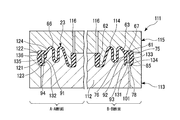
- the mold 111 has a lower mold 112 that supports the metal member 67, a middle mold 113 on which the lower mold 112 that supports the metal member 67 is set, and a lower mold 112 and an intermediate mold 113 that are elastic members 66. And an upper mold 115 for forming the cavity 114.
- the upper mold 115 is formed with a plurality of inlets 116 for injecting an unvulcanized rubber material into the cavity 114.
- the manufacturing method of the piston boot 23 is not limited to the method of injecting an unvulcanized rubber material into the cavity 114 and vulcanizing and molding, for example, charging the unvulcanized rubber material into the cavity 114 and adding it.
- a method of compression molding compression molding (compression molding method) may be used.
- the lower mold 112 has an annular shape as shown in FIG. As shown in FIG. 7, the lower mold 112 includes a forming surface 121 formed of a tapered surface for forming a tapered surface 85 of the outer peripheral surface portion 75 of the large-diameter fitting portion 61, and an inner peripheral surface portion 76 of the large-diameter fitting portion 61.
- a forming surface 122 formed of a cylindrical surface for forming the main inner peripheral surface 92, a forming surface 123 formed of a plane for forming the flat portion 78, and a forming surface 124 for forming a part of the bellows portion 63. And have.
- a cylindrical axial support protrusion 131 that protrudes outward in the axial direction from the formation surface 123 is formed in the inner area of the formation surface 123.
- a semi-cylindrical radial support protrusion 132 that protrudes radially outward from the formation surface 122 and protrudes axially outward from the formation surface 123 is formed at a boundary position between the formation surface 122 and the formation surface 123. ing.
- a plurality of axial support protrusions 131 are formed at equal intervals in the circumferential direction of the lower mold 112.
- a plurality of radial support protrusions 132 are also formed at equal intervals in the circumferential direction of the lower mold 112.
- the plurality of axial support protrusions 131 are arranged one by one at the center position between the radial support protrusions 132 adjacent in the circumferential direction of the lower mold 112. Therefore, in the lower mold 112, the axial support protrusions 131 and the radial support protrusions 132 are alternately arranged at equal intervals in the circumferential direction.
- the radial support protrusion 132 has a forming surface 135 formed of a semi-cylindrical surface and a forming surface 136 formed of a part of a conical surface having a certain point on the axial center as a vertex.
- the formation surface 135 is formed as a whole from the formation surface 123 to a position over the axial support protrusion 131, and the formation surface 136 is formed on the opposite side of the formation surface 135 from the formation surface 123.
- the formation surface 136 is inclined so that the height from the formation surface 122 in the radial direction of the lower mold 112 decreases as the formation surface 136 moves away from the formation surface 123.
- each outer peripheral surface 134 is a cylindrical surface.
- a metal member 67 is placed on the distal end surface 133 of these axial support protrusions 131. Accordingly, the plurality of axial support protrusions 131 support the metal member 67 in the axial direction and position the metal member 67 in the axial direction with respect to the lower mold 112.
- the plurality of radial support protrusions 132 have a minimum height from the formation surface 123 of each formation surface 135 higher than the axial support protrusion 131, and are placed on the plurality of axial support protrusions 131.
- the metal member 67 is fitted inside, and the metal member 67 is supported in the radial direction and positioned in the radial direction with respect to the lower mold 112.
- the formation surface 136 of the plurality of radial support projections 132 secures a gap with the metal member 67 toward the front side in the fitting direction. It is easy to insert. Thereafter, the formation surfaces 135 of the plurality of radial support protrusions 132 are fitted into the metal member 67 and positioned in the radial direction of the lower mold 112. In this way, the metal member 67 disposed on the middle mold 113 together with the lower mold 112 in the state of being set on the lower mold 112 is then divided into the upper mold 115 set on the middle mold 113, the lower mold 112, and the middle mold 113. It is positioned axially and radially with respect to the cavity 114 to be formed.
- the unvulcanized rubber material is injected from the plurality of inlets 116 into the cavity 114 in which the metal member 67 is set, and the cavity 114 is filled with the unvulcanized rubber material. Thereafter, the unvulcanized rubber material is vulcanized and formed into an elastic member 66. As a result, the piston boot 23 in which the metal member 67 is embedded in the elastic member constituting portion 71 of the elastic member 66 is completed.
- the forming surface 121 of the lower mold 112 forms the tapered surface 85.
- the formation surface 122 of the lower mold 112 forms the main inner peripheral surface 92.
- the formation surface 123 of the lower mold 112 forms the flat portion 78.
- the axial support protrusion 131 of the lower mold 112 forms the hole 101.
- the radial support protrusion 132 of the lower mold 112 forms a notch 91.
- the notch 91 is the main part. It is formed from the inner peripheral surface 92 to the position of the inner peripheral surface 93 of the metal member 67.
- the notch 91 is formed from the main inner peripheral surface 92 to the metal member 67. It is formed up to a position near the inner peripheral surface 93.
- the hole 101 is formed in the flat portion 78. To the position of the end surface 94 of the metal member 67. On the other hand, if there is a gap between the front end surface 133 of the axial support protrusion 131 and the end surface 94 of the metal member 67 due to rubber pressure or the like, the hole 101 extends from the flat portion 78 to the vicinity of the end surface 94 of the metal member 67. To the position.
- the plurality of holes 101 of the piston boot 23 are portions formed by a plurality of axial support protrusions 131.
- the plurality of notches 91 of the piston boot 23 are portions formed by a plurality of radial support protrusions 132.
- the bottom surface 100 of the hole 101 is formed by the front end surface 133 of the axial support protrusion 131.
- the wall surface 102 is formed by the outer peripheral surface 134 of the axial support protrusion 131.
- the curved concave surface 97 of the notch 91 is formed by the formation surface 135 of the radial support protrusion 132.
- the inclined surface 98 is formed by the forming surface 136.
- Patent Document 1 uses a piston boot having a structure in which an annular metal member is embedded in an annular end of an elastic body as a piston boot mounted between a piston and a cylinder.
- the metal member is supported in the axial direction and the radial direction by two support surfaces of L-shaped support portions provided in the mold.
- rip part is formed in the piston boot.
- the lip portion is formed, a sufficient area of the support surface that supports the metal member of the mold in the axial direction cannot be secured.
- the support portion of the mold for forming the piston boot is L-shaped, the shape is complicated and the manufacturing cost increases. Therefore, the cost of the piston boot is increased, and as a result, the cost of the disc brake is increased.
- the lip part first contacts the cylinder.
- This lip portion is easily deformable, and its bending direction is unstable in how it is deformed.
- the piston boot is press-fitted and fixed to the cylinder, it is necessary to check whether the lip portion does not bend in a specified direction and the assembly is not defective, which reduces productivity.
- the lip portion may be damaged during press-fitting.
- productivity may be reduced due to the lip portion. Therefore, the cost of the disc brake is increased.
- the annular large-diameter fitting portion 61 including the annular metal member 67 abuts on the inner peripheral surface 42 of the step portion 41 at the outer peripheral surface portion 75, and the annular flat surface.
- the part 78 contacts the annular wall surface 43 of the step part 41. Thereby, it becomes a shape which does not have a lip part which contact
- a plurality of holes 101 having a bottom surface 100 are opened in the annular flat portion 78 at the position of the metal member 67 or in the vicinity of the metal member 67, respectively. Accordingly, the area for supporting the metal member 67 by the axial support protrusion 131 of the lower mold 112 that leaves the plurality of holes 101 as traces can be increased. Therefore, it is possible to suppress a decrease in productivity due to a lack of support area. Therefore, an increase in cost of the piston boot 23 can be suppressed, and consequently an increase in cost of the disc brake 10 can be suppressed.
- the large-diameter fitting portion 61 includes a plurality of parts cut out in the radial direction (disk radial direction) of the metal member 67 in the radial inner side (disk radial direction inner side) of the metal member 67 than the metal member 67.
- a notch 91 is formed. These notches 91 are formed at different positions in the circumferential direction of the large-diameter fitting portion 61 with respect to the plurality of holes 101. Therefore, in the lower mold 112, the axial support protrusion 131 that leaves the hole 101 as a mark and the radial support protrusion 132 that leaves the notch 91 as a mark are at different positions in the circumferential direction. It is formed.
- the shapes of the axial support protrusion 131 and the radial support protrusion 132 are simplified and can be easily formed, and the cost increase of the lower mold 112 can be suppressed. Therefore, an increase in cost of the piston boot 23 can be suppressed, and consequently an increase in cost of the disc brake 10 can be suppressed.
- the disc brake 10 includes the piston 21 that presses one of the pair of pads 13 and 14, but both the pads 13 and 14 of the pair of pads 13 and 14 are included. It may be provided with a piston that presses. That is, what is necessary is just to provide the piston which presses at least 1 pad of a pair of pads.
- a disc brake as a first aspect includes a piston that presses at least one of a pair of pads opposed to both sides of the disc, and the piston is movably accommodated, and one end is open and the tip of the piston is
- a cylinder having a projecting bore portion, and a step portion having an inner diameter larger than the inner diameter of the bore portion formed on the opening side of the bore portion; and between the front end side of the piston and the step portion of the cylinder
- the fitting portion includes an outer peripheral surface portion that contacts the inner peripheral surface of the step portion, and an annular flat surface portion that contacts the annular wall surface portion of the step portion. And having the plane portion A plurality of holes having a bottom surface in the vicinity of the position or the metal member of the genus members are opened, respectively.
- the piston boot as the second aspect is disposed between the tip side of the piston provided in the caliper of the disc brake and a step portion formed in the cylinder opening of the caliper, and with the movement of the piston
- a piston boot having a bellows part that can be expanded and contracted, the piston boot having an annular fitting part that is formed on one end side of the bellows part and encloses an annular metal member and fits into the step part.
- the fitting portion includes an outer peripheral surface portion that contacts the inner peripheral surface of the stepped portion, and an annular flat surface portion that contacts the annular wall surface portion of the stepped portion.
- a plurality of holes each having a bottom surface are opened at the position of the member or in the vicinity of the metal member.
- the piston boot has a shape that does not have a lip portion that contacts the annular wall surface of the stepped portion. Therefore, it is possible to suppress a decrease in productivity due to the lip portion. Therefore, an increase in the cost of the disc brake can be suppressed.
- the disc brake as a third aspect is the disc brake according to the first aspect, wherein the fitting portion opens inward in the disc radial direction at a location inside the disc radial direction with respect to the metal member, and extends in the disc axial direction. A plurality of notches are formed along the same.
- the disc brake as the fourth aspect according to the third aspect is such that, in the third aspect, the radially outer position of the notch is the position of the inner peripheral surface of the metal member or the vicinity of the inner peripheral surface of the metal member. Is in position.
- the plurality of holes and the notch portions are formed at different positions in the circumferential direction of the fitting portion. ing.
- the piston boot as a 6th aspect is the 2nd aspect.
- the said fitting part is on the inner peripheral surface of the said fitting part between the inner peripheral surface of this fitting part, and the said metal member. It has an opening and a notch that is formed to be recessed outward in the radial direction.
- the piston boot according to a seventh aspect is the piston boot according to the sixth aspect, wherein the radially outer position of the notch is the position of the inner peripheral surface of the metal member or the vicinity of the inner peripheral surface of the metal member. Is in position.
- the plurality of holes and the notch portions are formed at different positions in the circumferential direction of the fitting portion. ing. Therefore, the shape of the portion for forming the plurality of holes of the mold and the shape of the portion for forming the notch are simplified, and the formation can be facilitated, and an increase in the cost of the mold can be suppressed. Therefore, an increase in the cost of the piston boot can be suppressed, and consequently an increase in the cost of the disc brake can be suppressed.
- the rubber member is exemplified as the elastic member, but a resin material may be used as the elastic member.
- the above-described disc brake and piston boot can suppress an increase in cost.
Landscapes
- Engineering & Computer Science (AREA)
- General Engineering & Computer Science (AREA)
- Mechanical Engineering (AREA)
- Manufacturing & Machinery (AREA)
- Braking Arrangements (AREA)
- Sealing Devices (AREA)
- Diaphragms And Bellows (AREA)
- Injection Moulding Of Plastics Or The Like (AREA)
Abstract
このピストンブーツ(23)は、蛇腹部(63)の一端側に形成され、環状の金属部材(67)を内包してシリンダ(26)の段部(41)に嵌合する環状の嵌合部(61)を有する。嵌合部(61)は、段部(41)の内周面(42)に当接する外周面部(75)と、段部(41)の環状壁面部(43)に当接する環状の平面部(78)と、を有する。平面部(78)には、金属部材(67)の位置または金属部材(67)の近傍位置に底面を有する複数の孔(101)がそれぞれ開口している。
Description
本発明は、ディスクブレーキおよびピストンブーツに関する。
本願は、2016年5月27日に、日本に出願された特願2016-106416号に基づき優先権を主張し、その内容をここに援用する。
本願は、2016年5月27日に、日本に出願された特願2016-106416号に基づき優先権を主張し、その内容をここに援用する。
ディスクブレーキにおいて、ピストンとシリンダとの間に装着されるピストンブーツとして、環状の金属部材を弾性体に埋設した構造のピストンブーツを用いた構成を有する場合がある(例えば、特許文献1参照)。
上記構造のピストンブーツは生産性に課題があり、ひいてはディスクブレーキのコスト増の一因となる可能性がある。
本発明は、コスト増を抑制することができるディスクブレーキおよびピストンブーツを提供する。
本発明の第一の態様によれば、ディスクブレーキは、ディスクの両面にそれぞれ対向する一対のパッドのうち少なくとも一つを押圧するピストンと、前記ピストンを移動可能に収容し、一端が開口して前記ピストンの先端が突出するボア部を有し、該ボア部の開口側に該ボア部の内径よりも大きな内径を有する段部が形成されるシリンダと、前記ピストンの先端側と前記シリンダの段部との間に配置され、前記ピストンの移動に伴って伸縮可能な蛇腹部を有するピストンブーツと、を備え、前記ピストンブーツは、前記蛇腹部の一端側に形成され、環状の金属部材を内包して前記段部に嵌合する環状の嵌合部を有し、該嵌合部は、前記段部の内周面に当接する外周面部と、前記段部の環状壁面部に当接する環状の平面部と、を有し、該平面部には、前記金属部材の位置または前記金属部材の近傍位置に底面を有する複数の孔がそれぞれ開口している。
本発明の第二の態様によれば、前記嵌合部は、前記金属部材よりもディスク径方向内側の部位に、ディスク径方向内方に開口し、ディスク軸方向に沿って形成される複数の切欠部を備えてよい。
本発明の第三の態様によれば、前記切欠部の径方向外方位置は、前記金属部材の内周面の位置、または、前記金属部材の内周面の近傍位置となっていてよい。
本発明の第四の態様によれば、前記複数の孔と前記切欠部とは、前記嵌合部の周方向の異なる位置に形成されてよい。
本発明の第五の態様によれば、ピストンブーツは、ディスクブレーキのキャリパに設けられるピストンの先端側と、前記キャリパのシリンダ開口に形成される段部との間に配置され、前記ピストンの移動に伴って伸縮可能な蛇腹部を有するピストンブーツであって、前記ピストンブーツは、前記蛇腹部の一端側に形成され、環状の金属部材を内包して前記段部に嵌合する環状の嵌合部を有し、該嵌合部は、前記段部の内周面に当接する外周面部と、前記段部の環状壁面部に当接する環状の平面部と、を有し、該平面部には、前記金属部材の位置または前記金属部材の近傍位置に底面を有する複数の孔がそれぞれ開口している。
本発明の第六の態様によれば、前記嵌合部は、該嵌合部の内周面と前記金属部材との間に、前記嵌合部の内周面に開口し、径方向外方に向かって凹んで形成される切欠部を備えてよい。
本発明の第七の態様によれば、前記切欠部の径方向外方位置は、前記金属部材の内周面の位置、または前記金属部材の内周面の近傍位置となっていてよい。
本発明の第八の態様によれば、前記複数の孔と前記切欠部とは、前記嵌合部の周方向の異なる位置に形成されてよい。
上記したディスクブレーキおよびピストンブーツによれば、コスト増を抑制することができる。
実施形態を図面を参照して以下に説明する。
図1は、ディスクブレーキ10を示す図である。このディスクブレーキ10は、自動車等の車両用であり、具体的には四輪自動車用である。ディスクブレーキ10は、図示略の車輪と共に回転するディスク11の回転を止めることで車両を制動する。
図1は、ディスクブレーキ10を示す図である。このディスクブレーキ10は、自動車等の車両用であり、具体的には四輪自動車用である。ディスクブレーキ10は、図示略の車輪と共に回転するディスク11の回転を止めることで車両を制動する。
ディスクブレーキ10は、支持部材12と、一対のパッド13,14と、キャリパ15とを備えている。支持部材12は、ディスク11の外周側を跨いで配置されている。支持部材12は、車両の非回転部に固定される。一対のパッド13,14は、支持部材12にディスク11の軸方向に移動可能となるように支持されている。一対のパッド13,14は、ディスク11の両面にそれぞれ対向配置される。キャリパ15は、支持部材12にディスク11の軸方向に移動可能となるように支持されている。キャリパ15は、一対のパッド13,14を挟持してこれらをディスク11の両面に押圧する。
キャリパ15は、キャリパボディ20と、ピストン21と、ピストンシール22と、ピストンブーツ23とを有している。
キャリパボディ20は、シリンダ26と、シリンダ26からディスク11の外周を跨ぐように延出するブリッジ部27と、ブリッジ部27のシリンダ26とは反対側から延出してシリンダ26に対向する爪部28とを有している。
シリンダ26には、爪部28側に一端が開口するボア部30が形成されている。このボア部30は、ピストン21をディスク11の軸方向に移動可能となるように収容する。ボア部30が形成されることにより、シリンダ26は、爪部28とは反対側の底部31と、底部31の外周縁部から筒状をなして爪部28側に延出する筒状部32とを有している。
シリンダ26の底部31にはブレーキ液をボア部30内に導入するための貫通孔33が形成されている。
シリンダ26の底部31にはブレーキ液をボア部30内に導入するための貫通孔33が形成されている。
ボア部30は、ピストン21の移動を案内する円筒面であるガイド内周面35を有している。ボア部30は、このガイド内周面35よりも底部31側に、円環状の大径溝36を有している。大径溝36は、ガイド内周面35よりも径方向外方に凹む形状を有する。ボア部30は、ガイド内周面35の底部31とは反対側の中間位置に、円環状のピストンシール溝37を有している。ピストンシール溝37は、ガイド内周面35よりも径方向外方に凹む形状を有する。このピストンシール溝37は、その内径がガイド内周面35の内径よりも大径となっている。
シリンダ26には、ボア部30の開口側である爪部28側に、円環状の段部41が形成されている。段部41は、ボア部30のガイド内周面35よりも径方向外方に凹む形状を有する。段部41は、爪部28側に抜ける段形状をなしており、シリンダ26の開口位置に形成されている。段部41は、その内径がボア部30のガイド内周面35の内径よりも大径で、ピストンシール溝37および大径溝36の内径よりも大径となっている。つまり、段部41は、その内径がボア部30のいずれの位置の内径よりも大径となっている。
段部41は、ボア部30の中心軸を中心とする円筒状の図2に示す内周面42と、内周面42の軸方向のボア部30側にあってボア部30の中心軸に直交する平面状の環状壁面部43とを有している。段部41には、内周面42の環状壁面部43側の中間位置に、内周面42の円筒面からなる主内周面45よりも径方向外方に凹む円環状の係合溝46が形成されている。段部41の内周面42は、主内周面45と係合溝46の内表面とから構成されている。環状壁面部43は、ボア部30の中心軸に直交する平坦面であり、ボア部30の中心軸を中心とする円環状となっている。
図1に示すように、ピストン21は、底部51と筒状部52とを備えている。ピストン21は、筒状部52の底部51と反対側の端部が開口部53とされた有底筒状に形成されている。筒状部52の開口部53側には、円環状の係止溝55が形成されている。係止溝55は、筒状部52の円筒面からなる外径面54よりも径方向内方に凹む形状を有する。ピストン21は、底部51がボア部30内で底部31側に位置するようにボア部30に収容されている。ピストン21は、ボア部30に収容された状態で、爪部28側の先端、つまり開口部53側がボア部30よりも爪部28側に突出している。ピストン21には、ボア部30よりも突出する先端側に係止溝55が形成されている。つまり、係止溝55は、ボア部30よりも外側に配置されている。
ピストンシール22は、ボア部30のピストンシール溝37に嵌合されている。このピストンシール22の内周側にピストン21が嵌合されている。ピストンシール22は、シリンダ26とピストン21との隙間をシールすると共に、ボア部30のガイド内周面35とでピストン21を軸方向に移動可能に支持する。
ピストンブーツ23は、キャリパ15に設けられたピストン21の先端側の係止溝55と、キャリパ15のシリンダ26の開口位置に形成された段部41との間に配置される。
ピストンブーツ23は、これら係止溝55および段部41にそれぞれ係合されている。ピストンブーツ23は、ピストン21の係止溝55よりもボア部30側の部分のシリンダ26から露出する外周部を覆っている。
ピストンブーツ23は、これら係止溝55および段部41にそれぞれ係合されている。ピストンブーツ23は、ピストン21の係止溝55よりもボア部30側の部分のシリンダ26から露出する外周部を覆っている。
ピストンブーツ23は、シリンダ26の段部41に嵌合する環状の大径嵌合部61(嵌合部)と、ピストン21の係止溝55に嵌合する環状の小径嵌合部62と、これらの間で伸縮可能な蛇腹部63とを有している。言い換えれば、大径嵌合部61は蛇腹部63の一端側に形成され、小径嵌合部62は蛇腹部63の他端側に形成されている。さらに言い換えれば、ピストンブーツ23には、大径嵌合部61が一端側に形成され、小径嵌合部62が他端側に形成され、蛇腹部63が中間部に形成されている。
大径嵌合部61および小径嵌合部62は、いずれも図3に示すように円環状である。図2に示すように、小径嵌合部62が大径嵌合部61よりも内外径共に小径となっている。小径嵌合部62は、内周部がピストン21の係止溝55に嵌合する。大径嵌合部61は外周部がシリンダ26の段部41に嵌合する。ピストンブーツ23は、大径嵌合部61がシリンダ26に固定される。この固定状態において、小径嵌合部62がピストン21に固定されたピストンブーツ23は、ピストン21のシリンダ26に対する移動に伴って、シリンダ26およびピストン21に対し固定されていない中間の蛇腹部63が伸縮する。
ピストンブーツ23は、ゴム製の環状の弾性部材66の内部に環状の金属部材67が埋設されて構成される。金属部材67は、弾性部材66よりも剛性が高く、かつ、弾性部材66よりも変形しにくい。図4,図5に示すように、金属部材67は、径方向の厚さよりも軸方向の長さが長い円筒体である。金属部材67は、上記した大径嵌合部61に内包されている。大径嵌合部61は、金属部材67の全部と弾性部材66の一部である弾性部材構成部71とで円筒状に形成されている。蛇腹部63は弾性部材66のみで蛇腹状に形成されている。小径嵌合部62は弾性部材66のみで円筒状に形成されている。なお、本実施形態で金属部材67は上述の通り円筒体となっているが、多角形の筒体でもよい。
大径嵌合部61の弾性部材構成部71は、大径嵌合部61の外側部分を構成しており、円環状をなしている。弾性部材構成部71の径方向の内部、且つ軸方向の内部に金属部材67が配置されている。これら弾性部材構成部71および金属部材67は接着されていないが、両者を接着して一体化してもよい。弾性部材構成部71は、円筒状の金属部材67の内径側および外径側の両側を被覆しており、金属部材67の軸方向の両側をも被覆している。
環状の大径嵌合部61は、外周面部75と、内周面部76と、軸方向一端の平面部77と、軸方向他端の平面部78とを有している。外周面部75および内周面部76は円筒面状である。外周面部75および内周面部76は、同軸状に配置されている。平面部77,78は、いずれも、大径嵌合部61の中心軸に直交する平面である。大径嵌合部61の外周面部75、平面部77および平面部78は、いずれも全面が弾性部材構成部71となっている。弾性部材構成部71である内周面部76の平面部77側の端縁部から蛇腹部63の一端側が延出している。この蛇腹部63の他端側は小径嵌合部62の内周面の軸方向一側の端縁部に繋がっている。この小径嵌合部62における蛇腹部63の連結側と、大径嵌合部61における蛇腹部63の連結側とは、ピストンブーツ23の軸方向の反対側となっている。
大径嵌合部61の弾性部材構成部71は、基部81と、基部81の軸方向の中央位置から基部81よりも径方向外方に突出する環状の突状部82とを有している。大径嵌合部61の外周面部75は、全面が弾性部材構成部71である。外周面部75は、基部81の円筒面である主外周面83と、突状部82の表面と、基部81の軸方向の平面部78側のテーパ面85とから構成されている。
図4に示すように、大径嵌合部61の弾性部材構成部71には、大径嵌合部61の径方向における内周面部76と金属部材67の内周面93との間で、内周面部76の軸方向の平面部78側の一部と、平面部78の径方向の内周面部76側の一部とを結ぶように切欠部91が形成されている。切欠部91は、内周面部76に開口するとともに、内周面部76の円筒面である主内周面92よりも径方向外方に向かって凹んで形成されている。切欠部91の径方向外方位置は、金属部材67の内周面93の位置、または内周面93の近傍位置である。切欠部91が、金属部材67の内周面93まで形成されていると、この内周面93が外部に露出する。切欠部91が、内周面93の手前まで形成されていると、内周面93との間に薄い弾性部材構成部71の層が設けられる。
切欠部91は、平面部78に開口して軸方向に向かって凹んでいる。切欠部91は、平面部78から金属部材67の平面部78側の端面94を越えて形成されている。大径嵌合部61は、金属部材67よりも大径嵌合部61の径方向における内側の部位に、ディスク径方向の内方に開口し、ディクス軸方向に沿って形成される複数の切欠部91を備えている。このような切欠部91が図3に示すように大径嵌合部61の周方向に等間隔で複数形成されている。
図4に示すように、大径嵌合部61の内周面部76は、主内周面92と複数の切欠部91の内表面95とから構成されている。
図4に示すように、大径嵌合部61の内周面部76は、主内周面92と複数の切欠部91の内表面95とから構成されている。
切欠部91は、平面部78側に図3,図6に示すように半円筒面からなる湾曲凹面97を有している。切欠部91は、湾曲凹面97の平面部78とは反対側に平面からなる図4に示す傾斜面98を有している。湾曲凹面97は、図6に示すように大径嵌合部61の周方向の幅が主内周面92側ほど広くなる形状となっている。傾斜面98は、図4に示すように大径嵌合部61の径方向の深さが平面部78から離れるほど浅くなるように凹んでいる。湾曲凹面97は、平面部78から金属部材67の平面部78側の端面94を越える位置まで形成されている。
図3,図6に示すように、大径嵌合部61の弾性部材構成部71には、平面部78の範囲内に、平面部78から大径嵌合部61の軸方向に底面100を有して凹む有底の複数の孔101が形成されている。図3に示すように、複数の孔101と複数の切欠部91とは、大径嵌合部61の周方向の異なる位置に形成されている。具体的に、複数の孔101は、大径嵌合部61の周方向に隣り合う切欠部91間の中央位置に一つずつ配置されるように、大径嵌合部61の周方向に等間隔で配置されている。よって、大径嵌合部61には、その周方向に交互に切欠部91と孔101とが等間隔で配置されている。なお本実施形態では、上述の通り複数の孔101と複数の切欠部91とが大径嵌合部61の周方向の異なる位置に形成されている。しかしながら、これらは必ずしも異なる位置である必要はなく、これらの周方向位置は一致する位置であっても良い。
これらの孔101は、図6に示すように、円筒面からなる壁面102を有する円形孔である。孔101は、図5に示すように、金属部材67の平面部78側の端面94の位置または端面94の近傍位置まで形成されている。孔101が金属部材67の端面94の位置まで形成されると、孔101の底面100は端面94を含み、孔101によって端面94が外部に露出する。また、孔101が金属部材67の端面94の近傍位置まで形成されると、孔101の底面100は端面94との間に薄い弾性部材構成部71の層が設けられる。
金属部材67の周方向において孔101と位置が合う部分の径方向の厚さは、この孔101の直径よりも薄い。また、孔101は、金属部材67の周方向においてこの孔101と位置が合う部分を、金属部材67の径方向に横断するように配置されている。平面部78の範囲内にあることから、複数の孔101は、大径嵌合部61の外周面部75よりも径方向内側にあり、且つ大径嵌合部61の内周面部76の主内周面92よりも径方向外側にある。言い換えれば、大径嵌合部61の平面部78には、金属部材67の端面94の位置または端面94の近傍位置に底面100を有する複数の孔101がそれぞれ開口している。
図2に示すように、ピストンブーツ23は、大径嵌合部61が、その環状の外周面部75を段部41の環状の内周面42に当接させ、環状の平面部78を段部41の環状壁面部43に当接させて、シリンダ26に連結されている。このとき、大径嵌合部61は、突状部82を係合溝46に嵌合させる。これによって、大径嵌合部61が段部41に対して軸方向に位置決めされ、段部41から外れることが抑制される。このように位置決めされた状態で、大径嵌合部61は、径方向および軸方向の両方向に締め代をもって段部41に嵌合する。その結果、外周面部75は段部41の内周面42に密着し、平面部78は段部41の環状壁面部43に密着する。その際に、大径嵌合部61は、外周面部75を段部41の内周面42に全周連続するように密着させ、平面部78を環状壁面部43に全周連続するように密着させる。
また、ピストンブーツ23は、小径嵌合部62がピストン21の係止溝55に嵌合される。その際に小径嵌合部62は内周面が係止溝55の底面に全周連続するように密着する。このようにして、ピストンブーツ23の一端側がシリンダ26に連結され、ピストンブーツ23の他端側がピストン21に連結される。
図1に示すディスクブレーキ10は、キャリパ15のシリンダ26のボア部30内に貫通孔33からブレーキ液が導入されると、ピストン21の底部51にブレーキ圧が作用する。すると、ピストン21がディスク11側に前進し、ピストン21側のパッド13をディスク11に向かって押圧する。これにより、パッド13が移動してディスク11に接触する。また、この押圧の反力で、キャリパ15のキャリパボディ20が移動し、爪部28でパッド14をディスク11に向かって押圧する。これにより、パッド14が、ディスク11に接触する。
以上のようにして、キャリパ15は、ピストン21の作動により、ピストン21と爪部28とで一対のパッド13,14を両側から挟持してディスク11の両面に押圧する。その結果、キャリパ15は、ディスク11に摩擦抵抗を付与して、制動力を発生させる。ピストンブーツ23は、ピストン21のボア部30からの突出量の変化に応じて軸方向の距離が変化する大径嵌合部61と小径嵌合部62との距離の変化に蛇腹部63が伸縮することにより追従する。これにより、ピストンブーツ23は、ピストン21の係止溝55よりも底部51側のシリンダ26から露出する外周部への異物の付着と、ピストン21とボア部30との間の隙間への異物の進入とを常時規制する。
上記のピストンブーツ23を製造する際には、図7に示す金型111が用いられる。この金型111は、金属部材67を支持する下型112と、金属部材67を支持した状態の下型112がセットされる中型113と、下型112および中型113とで弾性部材66の形状のキャビティ114を形成する上型115とを有している。上型115には、キャビティ114内に未加硫のゴム材料を注入するための複数の注入口116が形成されている。なお、ピストンブーツ23の製造方法は、キャビティ114内に未加硫のゴム材料を注入して加硫成形する方法に限定されず、例えば、キャビティ114内に未加硫のゴム材料を仕込んで加硫成形する方法(コンプレッション成形法)を用いてもよい。
下型112は、図8に示すように円環状をなしている。下型112は、図7に示すように大径嵌合部61の外周面部75のテーパ面85を形成するためのテーパ面からなる形成面121と、大径嵌合部61の内周面部76の主内周面92を形成するための円筒面からなる形成面122と、平面部78を形成するための平面からなる形成面123と、蛇腹部63の一部を形成するための形成面124とを有している。
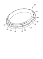
図8に示すように、形成面123の内側範囲には、形成面123よりも軸方向外方に突出する円柱状の軸方向支持突起部131が形成されている。形成面122と形成面123との境界位置には、形成面122よりも径方向外方に突出し形成面123よりも軸方向外方に突出する半円柱状の径方向支持突起部132が形成されている。軸方向支持突起部131は、下型112の周方向に等間隔で複数形成されている。径方向支持突起部132も、下型112の周方向に等間隔で複数形成されている。複数の軸方向支持突起部131は、下型112の周方向に隣り合う径方向支持突起部132間の中央位置に一つずつ配置される。よって、下型112には、その周方向に交互に軸方向支持突起部131と径方向支持突起部132とが等間隔で配置されている。
径方向支持突起部132は、半円筒面からなる形成面135と、軸心上のある一点を頂点とする円錐面の一部からなる形成面136とを有している。形成面135が全体として形成面123から軸方向支持突起部131を上側に越える位置まで形成されており、形成面136が形成面135の形成面123とは反対側に形成されている。形成面136は形成面123から離れるほど、下型112の径方向における形成面122からの高さが低くなるように傾斜している。
複数の軸方向支持突起部131は、形成面123とは反対側の先端面133が形成面123と平行であり、それぞれの形成面123から先端面133までの高さを合わせている。複数の軸方向支持突起部131は、それぞれの外周面134が円筒面となっている。これら軸方向支持突起部131の先端面133に金属部材67が載置される。これにより、複数の軸方向支持突起部131は、金属部材67をその軸方向に支持して下型112に対して軸方向に位置決めする。複数の径方向支持突起部132は、それぞれの形成面135の形成面123からの最低高さが軸方向支持突起部131よりも高くなっており、複数の軸方向支持突起部131に載置される金属部材67の内側に嵌合して、金属部材67をその径方向に支持して下型112に対して径方向に位置決めする。
ここで、金属部材67が複数の径方向支持突起部132に嵌合される際に、複数の径方向支持突起部132の形成面136が嵌合方向手前側ほど金属部材67との隙間を確保して挿入を容易としている。その後、複数の径方向支持突起部132の形成面135が金属部材67に嵌合して、これを下型112の径方向に位置決めする。このようにして、下型112にセットされた状態で下型112と共に中型113に配置される金属部材67は、その後、中型113にセットされる上型115と、下型112および中型113とで形成されるキャビティ114に対して軸方向および径方向に位置決めされる。
金属部材67がセットされたキャビティ114に、複数の注入口116から未加硫のゴム材料を注入してキャビティ114内を未加硫のゴム材料で満たす。その後、未加硫のゴム材料は、加硫成形されて弾性部材66となる。その結果、金属部材67を弾性部材66の弾性部材構成部71に埋設したピストンブーツ23ができ上がる。その際に、下型112の形成面121がテーパ面85を形成する。下型112の形成面122が主内周面92を形成する。下型112の形成面123が平面部78を形成する。下型112の軸方向支持突起部131が孔101を形成する。下型112の径方向支持突起部132が切欠部91を形成する。
ここで、未加硫のゴム材料のキャビティ114への注入時に、径方向支持突起部132の形成面135と金属部材67の内周面93との間に隙間がなければ、切欠部91は主内周面92から金属部材67の内周面93の位置まで形成される。他方、径方向支持突起部132の形成面135と金属部材67の内周面93との間にゴムの圧力等により隙間が生じれば、切欠部91は主内周面92から金属部材67の内周面93の近傍位置まで形成される。
同様に、未加硫のゴム材料のキャビティ114への注入時に、軸方向支持突起部131の先端面133と金属部材67の端面94との間に隙間がなければ、孔101は、平面部78から金属部材67の端面94の位置まで形成される。他方、軸方向支持突起部131の先端面133と金属部材67の端面94との間にゴムの圧力等により隙間が生じれば、孔101は、平面部78から金属部材67の端面94の近傍位置まで形成される。
ピストンブーツ23の複数の孔101は、複数の軸方向支持突起部131によって形成される部分である。ピストンブーツ23の複数の切欠部91は、複数の径方向支持突起部132によって形成される部分である。孔101の底面100は軸方向支持突起部131の先端面133によって形成される。壁面102は、軸方向支持突起部131の外周面134によって形成される。切欠部91の湾曲凹面97は径方向支持突起部132の形成面135によって形成される。傾斜面98は形成面136によって形成される。
特許文献1に記載された技術は、ピストンとシリンダとの間に装着されるピストンブーツとして、環状の金属部材を弾性体の環状の端部に埋設した構造のピストンブーツを用いている。このピストンブーツを製造する場合、金型に設けられたL字状の支え部の二カ所の支え面で金属部材を軸方向と径方向とに支持する。そして、このような支え部の痕として残る切欠部から異物が混入するのを防止するため、ピストンブーツにヒゲ状のリップ部を形成している。しかしながら、リップ部を形成すると、金型の金属部材を軸方向に支える支え面の面積が十分に確保できない。このため、金属部材を、金型へのセットに脱落等を生じることがないように注意してセットする必要があり、作業時間が多くかかって、生産性が低下してしまう可能性がある。よって、ピストンブーツのコストを増大させることになり、ひいてはディスクブレーキのコストを増大させてしまう。
また、ピストンブーツを成形するための金型の支え部がL字状であるため、形状が複雑で、製造コストが嵩んでしまう。よって、ピストンブーツのコストを増大させることになり、ひいてはディスクブレーキのコストを増大させてしまう。
また、ピストンブーツをシリンダへ圧入する際に、リップ部が最初にシリンダに接触する。このリップ部は変形容易であり、どのように変形するのかその曲がり方向が不安定である。このため、ピストンブーツをシリンダへ圧入固定する際に、リップ部が規定の方向に曲がらずに組み付け不良とならないか確認する必要があって生産性を低下させてしまう。また、圧入時にリップ部がダメージを受ける可能性もある。リップ部がダメージを受けると組み付けをやり直す必要があって生産性を低下させてしまう。このようにリップ部に起因して生産性を低下させてしまう可能性がある。よって、ディスクブレーキのコストを増大させてしまう。
これに対して、実施形態のピストンブーツ23は、環状の金属部材67を内包する環状の大径嵌合部61が、外周面部75で段部41の内周面42に当接し、環状の平面部78で段部41の環状壁面部43に当接する。これにより、段部41の環状壁面部43に当接するリップ部を持たない形状となる。よって、リップ部に起因した生産性低下を抑制することができる。したがって、ディスクブレーキ10のコスト増を抑制することができる。しかも、大径嵌合部61が、外周面部75で段部41の内周面42に当接し、環状の平面部78で段部41の環状壁面部43に当接することから、シリンダ26への組み付けが安定し、組み付け品質も向上できる。
また、環状の平面部78に、金属部材67の位置または金属部材67の近傍位置に底面100を有する複数の孔101がそれぞれ開口している。これにより、複数の孔101を痕として残すことになる下型112の軸方向支持突起部131が、金属部材67を支持するための面積を大きくできる。したがって、支持面積の不足による生産性低下を抑制することができる。よって、ピストンブーツ23のコスト増を抑制することができ、ひいてはディスクブレーキ10のコスト増を抑制することができる。
また、大径嵌合部61には、金属部材67よりも金属部材67の径方向内側(ディスク径方向内側)の部位に、金属部材67の径方向(ディスク径方向)に切り欠かれた複数の切欠部91が形成されている。これらの切欠部91は、複数の孔101に対して、大径嵌合部61の周方向の異なる位置に形成されている。このため、下型112において、孔101を痕として残すことになる軸方向支持突起部131と、切欠部91を痕として残すことになる径方向支持突起部132とが、周方向の異なる位置に形成される。よって、軸方向支持突起部131および径方向支持突起部132の形状が単純となって形成が容易となり、下型112のコスト増を抑制することができる。よって、ピストンブーツ23のコスト増を抑制することができ、ひいてはディスクブレーキ10のコスト増を抑制することができる。
以上に述べた実施形態のディスクブレーキ10は、一対のパッド13,14のうちの一つのパッド13を押圧するピストン21を備えるものであるが、一対のパッド13,14の両方のパッド13,14を押圧するピストンを備えるものであっても良い。つまり、一対のパッドのうちの少なくとも一つのパッドを押圧するピストンを備えていれば良い。
以上に述べた実施形態のディスクブレーキ及びピストンブーツは、例えば以下に述べる態様のものが考えられる。
第1の態様としてのディスクブレーキは、ディスクの両面にそれぞれ対向する一対のパッドのうち少なくとも一つを押圧するピストンと、前記ピストンを移動可能に収容し、一端が開口して前記ピストンの先端が突出するボア部を有し、該ボア部の開口側に該ボア部の内径よりも大きな内径を有する段部が形成されるシリンダと、前記ピストンの先端側と前記シリンダの段部との間に配置され、前記ピストンの移動に伴って伸縮可能な蛇腹部を有するピストンブーツと、を備え、前記ピストンブーツは、前記蛇腹部の一端側に形成され、環状の金属部材を内包して前記段部に嵌合する環状の嵌合部を有し、該嵌合部は、前記段部の内周面に当接する外周面部と、前記段部の環状壁面部に当接する環状の平面部と、を有し、該平面部には、前記金属部材の位置または前記金属部材の近傍位置に底面を有する複数の孔がそれぞれ開口している。
第1の態様としてのディスクブレーキは、ディスクの両面にそれぞれ対向する一対のパッドのうち少なくとも一つを押圧するピストンと、前記ピストンを移動可能に収容し、一端が開口して前記ピストンの先端が突出するボア部を有し、該ボア部の開口側に該ボア部の内径よりも大きな内径を有する段部が形成されるシリンダと、前記ピストンの先端側と前記シリンダの段部との間に配置され、前記ピストンの移動に伴って伸縮可能な蛇腹部を有するピストンブーツと、を備え、前記ピストンブーツは、前記蛇腹部の一端側に形成され、環状の金属部材を内包して前記段部に嵌合する環状の嵌合部を有し、該嵌合部は、前記段部の内周面に当接する外周面部と、前記段部の環状壁面部に当接する環状の平面部と、を有し、該平面部には、前記金属部材の位置または前記金属部材の近傍位置に底面を有する複数の孔がそれぞれ開口している。
また、第2の態様としてのピストンブーツは、ディスクブレーキのキャリパに設けられるピストンの先端側と、前記キャリパのシリンダ開口に形成される段部との間に配置され、前記ピストンの移動に伴って伸縮可能な蛇腹部を有するピストンブーツであって、前記ピストンブーツは、前記蛇腹部の一端側に形成され、環状の金属部材を内包して前記段部に嵌合する環状の嵌合部を有し、該嵌合部は、前記段部の内周面に当接する外周面部と、前記段部の環状壁面部に当接する環状の平面部と、を有し、該平面部には、前記金属部材の位置または前記金属部材の近傍位置に底面を有する複数の孔がそれぞれ開口している。したがって、ピストンブーツは、段部の環状壁面部に当接するリップ部を持たない形状となる。よって、リップ部に起因した生産性低下を抑制することができる。したがって、ディスクブレーキのコスト増を抑制することができる。
また、第3の態様としてのディスクブレーキは、第1の態様において、前記嵌合部が、前記金属部材よりもディスク径方向内側の部位に、ディスク径方向内方に開口し、ディスク軸方向に沿って形成される複数の切欠部を備えている。
また、第4の態様としてのディスクブレーキは、第3の態様において、前記切欠部の径方向外方位置が、前記金属部材の内周面の位置、または、前記金属部材の内周面の近傍位置となっている。
また、第5の態様としてのディスクブレーキは、第3の態様または第4の態様のいずれかにおいて、前記複数の孔と前記切欠部とが、前記嵌合部の周方向の異なる位置に形成されている。
また、第6の態様としてのピストンブーツは、第2の態様において、前記嵌合部が、該嵌合部の内周面と前記金属部材との間に、前記嵌合部の内周面に開口し、径方法外方に向かって凹んで形成される切欠部を備えている。
また、第7の態様としてのピストンブーツは、第6の態様において、前記切欠部の径方向外方位置が、前記金属部材の内周面の位置、または、前記金属部材の内周面の近傍位置となっている。
また、第8の態様としてのピストンブーツは、第6の態様または第7の態様のいずれかにおいて、前記複数の孔と前記切欠部とが、前記嵌合部の周方向の異なる位置に形成されている。よって、金型の複数の孔を形成する部分の形状および切欠部を形成する部分の形状が単純となって形成が容易となり、金型のコスト増を抑制することができる。よって、ピストンブーツのコスト増を抑制することができ、ひいてはディスクブレーキのコスト増を抑制することができる。
以上に述べた実施形態においては、弾性部材としてゴム材料を使用したものを例示したが、弾性部材として樹脂材料を使用してもよい。
以上に述べた実施形態においては、弾性部材としてゴム材料を使用したものを例示したが、弾性部材として樹脂材料を使用してもよい。
上記したディスクブレーキ及びピストンブーツによれば、コスト増を抑制することができる。
10 ディスクブレーキ
11 ディスク
13,14 パッド
15 キャリパ
21 ピストン
23 ピストンブーツ
26 シリンダ
30 ボア部
41 段部
42 内周面
43 環状壁面部
63 蛇腹部
67 金属部材
61 大径嵌合部(嵌合部)
75 外周面部
78 平面部
91 切欠部
100 底面
101 孔
11 ディスク
13,14 パッド
15 キャリパ
21 ピストン
23 ピストンブーツ
26 シリンダ
30 ボア部
41 段部
42 内周面
43 環状壁面部
63 蛇腹部
67 金属部材
61 大径嵌合部(嵌合部)
75 外周面部
78 平面部
91 切欠部
100 底面
101 孔
Claims (8)
- ディスクの両面にそれぞれ対向する一対のパッドのうち少なくとも一つを押圧するピストンと、
前記ピストンを移動可能に収容し、一端が開口して前記ピストンの先端が突出するボア部を有し、該ボア部の開口側に該ボア部の内径よりも大きな内径を有する段部が形成されるシリンダと、
前記ピストンの先端側と前記シリンダの段部との間に配置され、前記ピストンの移動に伴って伸縮可能な蛇腹部を有するピストンブーツと、を備え、
前記ピストンブーツは、前記蛇腹部の一端側に形成され、環状の金属部材を内包して前記段部に嵌合する環状の嵌合部を有し、
該嵌合部は、前記段部の内周面に当接する外周面部と、前記段部の環状壁面部に当接する環状の平面部と、を有し、
該平面部には、前記金属部材の位置または前記金属部材の近傍位置に底面を有する複数の孔がそれぞれ開口している
ディスクブレーキ。 - 前記嵌合部は、前記金属部材よりもディスク径方向内側の部位に、ディスク径方向内方に開口し、ディスク軸方向に沿って形成される複数の切欠部を備えている、請求項1に記載のディスクブレーキ。
- 前記切欠部の径方向外方位置は、前記金属部材の内周面の位置、または、前記金属部材の内周面の近傍位置となっている、請求項2に記載のディスクブレーキ。
- 前記複数の孔と前記切欠部とは、前記嵌合部の周方向の異なる位置に形成されている、請求項2又は3に記載のディスクブレーキ。
- ディスクブレーキのキャリパに設けられるピストンの先端側と、前記キャリパのシリンダ開口に形成される段部との間に配置され、前記ピストンの移動に伴って伸縮可能な蛇腹部を有するピストンブーツであって、
前記ピストンブーツは、前記蛇腹部の一端側に形成され、環状の金属部材を内包して前記段部に嵌合する環状の嵌合部を有し、
該嵌合部は、前記段部の内周面に当接する外周面部と、前記段部の環状壁面部に当接する環状の平面部と、を有し、
該平面部には、前記金属部材の位置または前記金属部材の近傍位置に底面を有する複数の孔がそれぞれ開口している
ピストンブーツ。 - 前記嵌合部は、該嵌合部の内周面と前記金属部材との間に、前記嵌合部の内周面に開口し、径方向外方に向かって凹んで形成される切欠部を備えている請求項5に記載のピストンブーツ。
- 前記切欠部の径方向外方位置は、前記金属部材の内周面の位置、または前記金属部材の内周面の近傍位置となっている、請求項6に記載のピストンブーツ。
- 前記複数の孔と前記切欠部とは、前記嵌合部の周方向の異なる位置に形成されている、請求項6又は7に記載のピストンブーツ。
Priority Applications (3)
| Application Number | Priority Date | Filing Date | Title |
|---|---|---|---|
| DE112017002696.2T DE112017002696T5 (de) | 2016-05-27 | 2017-05-26 | Scheibenbremse und Kolbenschutz |
| US15/998,957 US10883608B2 (en) | 2016-05-27 | 2017-05-26 | Disc brake and piston boot |
| CN201780011805.8A CN108700194B (zh) | 2016-05-27 | 2017-05-26 | 盘式制动器及活塞罩 |
Applications Claiming Priority (2)
| Application Number | Priority Date | Filing Date | Title |
|---|---|---|---|
| JP2016-106416 | 2016-05-27 | ||
| JP2016106416A JP6660810B2 (ja) | 2016-05-27 | 2016-05-27 | ディスクブレーキおよびピストンブーツ |
Publications (1)
| Publication Number | Publication Date |
|---|---|
| WO2017204329A1 true WO2017204329A1 (ja) | 2017-11-30 |
Family
ID=60412749
Family Applications (1)
| Application Number | Title | Priority Date | Filing Date |
|---|---|---|---|
| PCT/JP2017/019693 Ceased WO2017204329A1 (ja) | 2016-05-27 | 2017-05-26 | ディスクブレーキおよびピストンブーツ |
Country Status (5)
| Country | Link |
|---|---|
| US (1) | US10883608B2 (ja) |
| JP (1) | JP6660810B2 (ja) |
| CN (1) | CN108700194B (ja) |
| DE (1) | DE112017002696T5 (ja) |
| WO (1) | WO2017204329A1 (ja) |
Families Citing this family (6)
| Publication number | Priority date | Publication date | Assignee | Title |
|---|---|---|---|---|
| JP6934805B2 (ja) | 2017-10-31 | 2021-09-15 | 上野製薬株式会社 | 2,6−ナフタレンジカルボン酸の製造方法 |
| JP6896098B2 (ja) * | 2017-11-28 | 2021-06-30 | 日立Astemo株式会社 | ディスクブレーキおよびピストンブーツ |
| JP7114453B2 (ja) | 2018-12-19 | 2022-08-08 | 日立Astemo株式会社 | ディスクブレーキ及びピストンブーツ |
| US12595832B2 (en) * | 2022-10-21 | 2026-04-07 | Hl Mando Corporation | Brake housing |
| CN117627978A (zh) * | 2023-10-27 | 2024-03-01 | 西安航空制动科技有限公司 | 一种可调节响应速度的阀用活门组件 |
| US20260022771A1 (en) * | 2024-07-18 | 2026-01-22 | Hl Mando Corporation | Sealing assembly for vehicle disc brake apparatus |
Citations (3)
| Publication number | Priority date | Publication date | Assignee | Title |
|---|---|---|---|---|
| FR2685749A2 (en) * | 1988-10-28 | 1993-07-02 | Bendix France Sa | Piston cap |
| JP2860406B2 (ja) * | 1988-10-28 | 1999-02-24 | ベンディクス・フランス | ディスクブレーキ用ピストンキャップ |
| JP2014126193A (ja) * | 2012-12-27 | 2014-07-07 | Fukoku Co Ltd | リングモールド型ブーツ |
Family Cites Families (12)
| Publication number | Priority date | Publication date | Assignee | Title |
|---|---|---|---|---|
| US4084665A (en) * | 1976-10-22 | 1978-04-18 | The Bendix Corporation | Disc brake and mounting means therefor |
| DE3204989C2 (de) * | 1982-02-12 | 1983-12-15 | Fa. Carl Freudenberg, 6940 Weinheim | Kassettendichtung |
| US5499696A (en) * | 1993-07-27 | 1996-03-19 | Tokico Ltd. | Disk brake |
| DE19521634A1 (de) * | 1995-06-14 | 1996-12-19 | Teves Gmbh Alfred | Scheibenbremse mit automatischer Nachstellvorrichtung |
| WO2002044580A1 (en) * | 2000-11-30 | 2002-06-06 | Freni Brembo S.P.A. | A protective boot for a piston-cylinder unit of a disk brake |
| DE10322834B4 (de) * | 2003-05-19 | 2008-10-02 | Knorr-Bremse Systeme für Nutzfahrzeuge GmbH | Pneumatisch oder elektromotorisch betätigbare Scheibenbremse |
| CN2789504Y (zh) * | 2005-05-11 | 2006-06-21 | 陈晓东 | 液压盘式制动器 |
| JP2009019643A (ja) | 2007-07-10 | 2009-01-29 | Advics:Kk | リングモールド型ブーツおよびその製造方法 |
| IT1401114B1 (it) * | 2010-07-05 | 2013-07-12 | Freni Brembo Spa | Guaina di protezione di un gruppo pistone-cilindro di un freno a disco |
| JP6011997B2 (ja) * | 2012-10-12 | 2016-10-25 | Nok株式会社 | ボールジョイント用ダストカバー |
| DE102013015002A1 (de) * | 2013-09-10 | 2015-03-12 | Wabco Europe Bvba | Scheibenbremse, insbesondere für Nutzfahrzeuge |
| JP6305447B2 (ja) | 2016-01-28 | 2018-04-04 | エーファウ・グループ・エー・タルナー・ゲーエムベーハー | キャリア基板を外すための屈曲可能なキャリア台、デバイス、および方法 |
-
2016
- 2016-05-27 JP JP2016106416A patent/JP6660810B2/ja active Active
-
2017
- 2017-05-26 CN CN201780011805.8A patent/CN108700194B/zh active Active
- 2017-05-26 US US15/998,957 patent/US10883608B2/en active Active
- 2017-05-26 DE DE112017002696.2T patent/DE112017002696T5/de active Pending
- 2017-05-26 WO PCT/JP2017/019693 patent/WO2017204329A1/ja not_active Ceased
Patent Citations (3)
| Publication number | Priority date | Publication date | Assignee | Title |
|---|---|---|---|---|
| FR2685749A2 (en) * | 1988-10-28 | 1993-07-02 | Bendix France Sa | Piston cap |
| JP2860406B2 (ja) * | 1988-10-28 | 1999-02-24 | ベンディクス・フランス | ディスクブレーキ用ピストンキャップ |
| JP2014126193A (ja) * | 2012-12-27 | 2014-07-07 | Fukoku Co Ltd | リングモールド型ブーツ |
Also Published As
| Publication number | Publication date |
|---|---|
| CN108700194A (zh) | 2018-10-23 |
| JP6660810B2 (ja) | 2020-03-11 |
| JP2017211066A (ja) | 2017-11-30 |
| US10883608B2 (en) | 2021-01-05 |
| US20200141498A1 (en) | 2020-05-07 |
| CN108700194B (zh) | 2020-08-18 |
| DE112017002696T5 (de) | 2019-02-14 |
Similar Documents
| Publication | Publication Date | Title |
|---|---|---|
| JP6660810B2 (ja) | ディスクブレーキおよびピストンブーツ | |
| JP7611986B2 (ja) | ディスクブレーキ | |
| JP4639619B2 (ja) | 往復動軸用密封装置 | |
| US11486455B2 (en) | Disc brake and piston boot | |
| US12000445B2 (en) | Disc brake and piston boot | |
| JP4935997B2 (ja) | 油圧クラッチ用ピストン | |
| CN105102853B (zh) | 液封式防振装置 | |
| JP6429386B2 (ja) | ディスクブレーキおよびピストンの製造方法 | |
| JP2007107550A (ja) | 往復動軸用密封装置 | |
| JP6983634B2 (ja) | ディスクブレーキ | |
| JP6921024B2 (ja) | ディスクブレーキ | |
| JPWO2016181896A1 (ja) | ディスクブレーキ | |
| JP2009068672A (ja) | 密封装置及びその製造方法 | |
| JP2006138398A (ja) | クラッチピストン | |
| JP6463890B2 (ja) | リングモールド型ブーツおよびその製造方法 | |
| JP2004190841A (ja) | ディスクブレーキのダストブーツ取付構造 | |
| JP2019132312A (ja) | 車両用ディスクブレーキ | |
| JP2018123883A (ja) | キャリパおよびキャリパの製造方法 | |
| JP2014015982A (ja) | ディスクブレーキ装置 | |
| JP2019209354A (ja) | 金型装置および製造方法 | |
| JP2015121306A (ja) | ディスクブレーキ | |
| JP2005226731A (ja) | ディスクブレーキ | |
| JP2009052608A (ja) | 自動変速機用ピストン |
Legal Events
| Date | Code | Title | Description |
|---|---|---|---|
| WWE | Wipo information: entry into national phase |
Ref document number: MX/A/2018/010077 Country of ref document: MX |
|
| 121 | Ep: the epo has been informed by wipo that ep was designated in this application |
Ref document number: 17802915 Country of ref document: EP Kind code of ref document: A1 |
|
| 122 | Ep: pct application non-entry in european phase |
Ref document number: 17802915 Country of ref document: EP Kind code of ref document: A1 |