WO2017204005A1 - 異常検知装置及び報知装置 - Google Patents
異常検知装置及び報知装置 Download PDFInfo
- Publication number
- WO2017204005A1 WO2017204005A1 PCT/JP2017/018001 JP2017018001W WO2017204005A1 WO 2017204005 A1 WO2017204005 A1 WO 2017204005A1 JP 2017018001 W JP2017018001 W JP 2017018001W WO 2017204005 A1 WO2017204005 A1 WO 2017204005A1
- Authority
- WO
- WIPO (PCT)
- Prior art keywords
- light
- abnormality
- sensor
- detected
- illuminance
- Prior art date
- Legal status (The legal status is an assumption and is not a legal conclusion. Google has not performed a legal analysis and makes no representation as to the accuracy of the status listed.)
- Ceased
Links
Images


Classifications
-
- B—PERFORMING OPERATIONS; TRANSPORTING
- B60—VEHICLES IN GENERAL
- B60Q—ARRANGEMENT OF SIGNALLING OR LIGHTING DEVICES, THE MOUNTING OR SUPPORTING THEREOF OR CIRCUITS THEREFOR, FOR VEHICLES IN GENERAL
- B60Q11/00—Arrangement of monitoring devices for devices provided for in groups B60Q1/00 - B60Q9/00
- B60Q11/005—Arrangement of monitoring devices for devices provided for in groups B60Q1/00 - B60Q9/00 for lighting devices, e.g. indicating if lamps are burning or not
-
- B—PERFORMING OPERATIONS; TRANSPORTING
- B60—VEHICLES IN GENERAL
- B60Q—ARRANGEMENT OF SIGNALLING OR LIGHTING DEVICES, THE MOUNTING OR SUPPORTING THEREOF OR CIRCUITS THEREFOR, FOR VEHICLES IN GENERAL
- B60Q1/00—Arrangement of optical signalling or lighting devices, the mounting or supporting thereof or circuits therefor
- B60Q1/02—Arrangement of optical signalling or lighting devices, the mounting or supporting thereof or circuits therefor the devices being primarily intended to illuminate the way ahead or to illuminate other areas of way or environments
- B60Q1/04—Arrangement of optical signalling or lighting devices, the mounting or supporting thereof or circuits therefor the devices being primarily intended to illuminate the way ahead or to illuminate other areas of way or environments the devices being headlights
-
- B—PERFORMING OPERATIONS; TRANSPORTING
- B60—VEHICLES IN GENERAL
- B60Q—ARRANGEMENT OF SIGNALLING OR LIGHTING DEVICES, THE MOUNTING OR SUPPORTING THEREOF OR CIRCUITS THEREFOR, FOR VEHICLES IN GENERAL
- B60Q11/00—Arrangement of monitoring devices for devices provided for in groups B60Q1/00 - B60Q9/00
-
- H—ELECTRICITY
- H05—ELECTRIC TECHNIQUES NOT OTHERWISE PROVIDED FOR
- H05B—ELECTRIC HEATING; ELECTRIC LIGHT SOURCES NOT OTHERWISE PROVIDED FOR; CIRCUIT ARRANGEMENTS FOR ELECTRIC LIGHT SOURCES, IN GENERAL
- H05B45/00—Circuit arrangements for operating light-emitting diodes [LED]
- H05B45/50—Circuit arrangements for operating light-emitting diodes [LED] responsive to malfunctions or undesirable behaviour of LEDs; responsive to LED life; Protective circuits
- H05B45/58—Circuit arrangements for operating light-emitting diodes [LED] responsive to malfunctions or undesirable behaviour of LEDs; responsive to LED life; Protective circuits involving end of life detection of LEDs
-
- H—ELECTRICITY
- H05—ELECTRIC TECHNIQUES NOT OTHERWISE PROVIDED FOR
- H05B—ELECTRIC HEATING; ELECTRIC LIGHT SOURCES NOT OTHERWISE PROVIDED FOR; CIRCUIT ARRANGEMENTS FOR ELECTRIC LIGHT SOURCES, IN GENERAL
- H05B47/00—Circuit arrangements for operating light sources in general, i.e. where the type of light source is not relevant
- H05B47/20—Responsive to malfunctions or to light source life; for protection
-
- Y—GENERAL TAGGING OF NEW TECHNOLOGICAL DEVELOPMENTS; GENERAL TAGGING OF CROSS-SECTIONAL TECHNOLOGIES SPANNING OVER SEVERAL SECTIONS OF THE IPC; TECHNICAL SUBJECTS COVERED BY FORMER USPC CROSS-REFERENCE ART COLLECTIONS [XRACs] AND DIGESTS
- Y02—TECHNOLOGIES OR APPLICATIONS FOR MITIGATION OR ADAPTATION AGAINST CLIMATE CHANGE
- Y02B—CLIMATE CHANGE MITIGATION TECHNOLOGIES RELATED TO BUILDINGS, e.g. HOUSING, HOUSE APPLIANCES OR RELATED END-USER APPLICATIONS
- Y02B20/00—Energy efficient lighting technologies, e.g. halogen lamps or gas discharge lamps
- Y02B20/40—Control techniques providing energy savings, e.g. smart controller or presence detection
Definitions
- the present invention relates to an abnormality detection device and a notification device, and more particularly to an abnormality detection device and a notification device that detect a light abnormality.
- Patent Document 1 discloses a monitoring system that detects an abnormality in LED (Light Emitting Diode) illumination.
- the monitoring system includes a camera and LED lighting. According to this monitoring system, it is possible to detect an abnormality in the LED illumination by recognizing the luminance of the specific character pattern photographed by the camera when the LED illumination is emitted.
- the present invention has been made to solve such a problem, and an object of the present invention is to provide an abnormality detection device and a notification device capable of detecting an abnormality of a light regardless of a time zone and surrounding environment. Is to provide.
- An abnormality detection device detects a light abnormality.
- the abnormality detection device includes a sensor, a memory, and a control unit.
- the sensor detects a physical quantity related to the light.
- the memory stores a reference for detecting a light abnormality.
- the control unit detects an abnormality of the light based on the difference between the physical quantity detected by the sensor while the light is turned on and the physical quantity detected by the sensor while the light is turned off, and the reference.
- the sensor continuously detects the physical quantity while the light is on.
- the control unit detects an abnormality of the light based on a difference between the physical quantity detected by the sensor at the start of lighting of the light and the physical quantity continuously detected by the sensor during the lighting of the light.
- the control unit determines that a difference between a physical quantity detected by the sensor at the start of lighting of the light and a physical quantity continuously detected by the sensor during lighting of the light has a first predetermined value. Detects an abnormal light when it exceeds
- this abnormality detection device when the difference between the physical quantity detected by the sensor at the start of lighting of the light and the physical quantity continuously detected by the sensor during lighting of the light exceeds the first predetermined value even once. A light abnormality is detected. Therefore, according to this abnormality detection device, it is possible to detect a light abnormality when there is any doubt about a light abnormality.
- the control unit determines that a difference between a physical quantity detected by the sensor at the start of lighting of the light and a physical quantity continuously detected by the sensor during lighting of the light has a first predetermined value. A light abnormality is detected when the frequency exceeds the predetermined frequency.
- this abnormality detection device if the difference between the physical quantity detected by the sensor at the start of lighting of the light and the physical quantity continuously detected by the sensor during lighting of the light exceeds the first predetermined value once, the light is detected. Is not detected and the light abnormality is detected only when the frequency exceeds a predetermined frequency. Therefore, according to this abnormality detection device, it is possible to detect an abnormality in the light after the possibility that an abnormality has occurred in the light is increased.
- the sensor is an illuminance sensor, and the physical quantity is illuminance.
- the sensor is a color sensor, and the physical quantity is color information.
- An abnormality detection device detects a light abnormality.
- the abnormality detection device includes an illuminance sensor, a color sensor, and a control unit.
- the illuminance sensor detects the illuminance of the light.
- the color sensor detects the illuminance and color information of the light.
- the control unit detects a light abnormality based on the illuminance detected by the illuminance sensor or the color information detected by the color sensor. Then, the control unit determines that the illuminance sensor or the color sensor is abnormal when the difference between the illuminance detected by the illuminance sensor and the illuminance detected by the color sensor exceeds a second predetermined value.
- the abnormality of the light cannot be accurately detected if an abnormality occurs in the illuminance sensor or the color sensor. If the illuminance sensor and the color sensor are normal, the illuminance detected by the illuminance sensor and the illuminance detected by the color sensor should be substantially the same. In this abnormality detection device, it is determined that the illuminance sensor or the color sensor is abnormal when the difference between the illuminance detected by the illuminance sensor and the illuminance detected by the color sensor exceeds a second predetermined value. . Therefore, according to this abnormality detection device, an abnormality of the illuminance sensor or the color sensor can be detected, and as a result, an abnormality of the light can be accurately detected.
- an abnormality detection device and a notification device that can detect an abnormality of a light regardless of the time zone and the surrounding environment.
- FIG. 1 is an overall configuration diagram of an abnormality detection system to which an abnormality detection apparatus according to Embodiment 1 is applied. It is a flowchart which shows the process sequence of abnormality detection of light. It is a figure which shows the change of the illumination intensity by a light lighting continuously. It is a figure which shows another example of the illumination intensity change in case abnormality of a light is detected. It is a flowchart which shows the alerting
- reporting part. 10 is a flowchart illustrating a processing procedure for detecting an abnormality of a light in a modification of the first embodiment. It is a whole block diagram of the abnormality detection system to which the abnormality detection apparatus according to Embodiment 2 is applied.
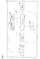
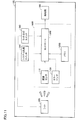
- FIG. 1 is an overall configuration diagram of an abnormality notification system to which an abnormality detection device according to the first embodiment is applied.
- abnormality notification system 10 includes an abnormality detection device 100, a light 200, a notification unit 300, a system activation switch 350, and a light lighting switch 360.
- an abnormality of the light 200 is detected by the abnormality detection device 100.
- the abnormality detection device 100 controls the notification unit 300 so as to notify the user to replace or repair the light 200.
- the user can recognize the necessity of replacement or repair of the light 200 before the failure of the light 200.
- the light 200 is a light source that emits light when receiving power from a power source (not shown).
- the light 200 is, for example, LED lighting or a vehicle headlight.
- the notification unit 300 performs notification for prompting the user to replace or repair the light 200.
- the notification unit 300 receives the instruction from the abnormality detection device 100 and performs the above notification.
- the notification unit 300 is, for example, a display or a speaker.
- a screen prompting the user to replace or repair the light 200 is displayed on the display when the light 200 is abnormal.
- the system start switch 350 is a switch for starting or stopping the abnormality notification system 10.
- the user can start or stop the abnormality notification system 10 by operating the system start switch 350.
- the system activation switch 350 may be, for example, a push type switch or a slide type switch.
- the system activation switch 350 may be a vehicle start switch or an ignition key.
- the light lighting switch 360 is a switch for turning on or off the light 200. The user can turn on or off the light 200 by operating the light lighting switch 360.
- the light lighting switch 360 may be, for example, a push-type switch or a slide-type switch.
- the abnormality detection device 100 includes an illuminance sensor 110, a memory 120, and a controller 130.
- the illuminance sensor 110 detects the illuminance of the light 200 (an example of a physical quantity related to the light 200).
- the illuminance sensor 110 is disposed at a position where the light from the light 200 can be received.
- the memory 120 stores a reference illuminance (an example of a reference amount) serving as a reference for detecting an abnormality of the light 200.
- the reference illuminance will be described in detail later.
- the memory 120 is a non-volatile memory such as a flash memory, for example.
- the controller 130 detects an abnormality of the light 200 based on the illuminance of the light 200 detected by the illuminance sensor 110 and the reference illuminance stored in the memory 120. A method for detecting the abnormality of the light 200 by the controller 130 will be described in detail later.
- the illuminance sensor 110 receives not only light emitted from the light 200 but also external light such as sunlight. Therefore, the illuminance detected by the illuminance sensor 110 is the illuminance due to the light of the light 200 and external light. If the abnormality detection of the light 200 is always performed in the situation where the brightness of the external light is almost the same, the abnormality of the light 200 can be detected by simply monitoring the illuminance detected by the illuminance sensor 110. .
- the abnormality detection of the light 200 is not necessarily performed in a situation where the brightness of the external light is the same. Depending on the time of day and the surrounding environment, the influence of external light may be large. In this case, the abnormality of the light 200 cannot be detected simply by monitoring the illuminance detected by the illuminance sensor 110.
- the controller 130 determines the difference between the illuminance detected by the illuminance sensor 110 while the light 200 is turned on and the illuminance detected by the illuminance sensor 110 while the light 200 is turned off. And an abnormality of the light 200 is detected based on the reference illuminance. More specifically, the controller 130 determines that the difference between the illuminance detected by the illuminance sensor 110 while the light 200 is turned on and the illuminance detected by the illuminance sensor 110 while the light 200 is turned off falls below the reference illuminance. An abnormality of the light 200 is detected.
- the reference illuminance for example, a value of 80% of the illuminance when the light 200 is new (no influence of outside light) is set.
- the difference between the illuminance detected by the illuminance sensor 110 while the light 200 is turned on and the illuminance detected by the illuminance sensor 110 while the light 200 is turned off is based on the illuminance detected by the illuminance sensor 110 while the light 200 is turned on.
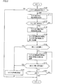
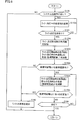
- FIG. 2 is a flowchart showing a processing procedure for detecting an abnormality of the light 200. Referring to FIG. 2, the processing shown by this flowchart is repeatedly executed by being called from a main routine (not shown) in controller 130 during operation of abnormality notification system 10.
- the controller 130 determines whether or not an activation instruction for the abnormality notification system 10 has been received from the user through the system activation switch 350 (step S100).
- indication of the abnormality notification system 10 among the controllers 130 is operate
- step S100 If it is determined that the activation instruction for the abnormality notification system 10 has not been received (NO in step S100), the process returns to the main routine. On the other hand, when it is determined that the activation instruction for abnormality notification system 10 has been received (YES in step S100), controller 130 stores in memory 120 sensor data (illuminance information) detected by illuminance sensor 110 while light 200 is turned off. (Step S110). As described above, this sensor data is used to remove the influence of light other than the light 200 included in the sensor data of the illuminance sensor 110 when the light 200 is lit.
- step S120 determines whether or not an instruction to turn on the light 200 is received from the user through the light turn-on switch 360. If it is determined that an instruction to turn on light 200 has not been received (NO in step S120), the process again proceeds to step S110, and controller 130 updates sensor data during turn-off of light 200 stored in memory 120. .
- controller 130 stores, in memory 120, the illuminance information detected by illuminance sensor 110 at the start of lighting of light 200 (immediately after lighting of light 200).
- step S130 the timing at which the illuminance information is stored in the memory (at the start of lighting of the light 200) is not necessarily immediately after the lighting of the light 200, and may be, for example, after a lapse of a predetermined time from the start of lighting of the light 200.
- the controller 130 accesses the memory 120 to calculate a difference D1 between the illuminance detected by the illuminance sensor 110 when the light 200 starts lighting and the illuminance detected by the illuminance sensor 110 while the light 200 is turned off (Ste S140). Specifically, the controller 130 performs a calculation of subtracting the illuminance while the light 200 is turned off from the illuminance when the light 200 is turned on.
- the difference D1 corresponds to a value obtained by removing the influence of light other than the light 200 from the sensor data of the illuminance sensor 110 when the light 200 is lit.
- the controller 130 determines whether or not the difference D1 is below the reference amount (reference illuminance) stored in the memory 120 (step S150).
- the reference illuminance is, for example, a value that is 80% of the illuminance when the light 200 is new (no influence from outside light). That is, in step S150, it is determined whether the illuminance of the light 200 has decreased by a predetermined value or more since the new time.
- the controller 130 If it is determined that the calculated difference D1 is less than the reference illuminance (YES in step S150), the controller 130 detects an abnormality of the light 200 because there is a high possibility that the failure time of the light 200 is approaching. Then, the abnormality detection signal is output to the notification unit 300 (step S190). Processing in the notification unit 300 after receiving the abnormality detection signal will be described in detail later.
- step S150 if it is determined that the calculated difference D1 is greater than or equal to the reference illuminance (NO in step S150), there is a high possibility that no abnormality has occurred in the light 200 at least immediately after the light 200 is turned on. In this case, the controller 130 performs steps S160 to S180 until the light 200 is extinguished so that the abnormality can be detected even when an abnormality occurs in the light 200 during the subsequent continuous lighting. Repeatedly.
- the controller 130 first calculates a difference D2 (absolute value) between the illuminance detected by the illuminance sensor 110 at the start of lighting of the light 200 and the illuminance currently detected by the illuminance sensor 110 (step S160). Specifically, the controller 130 calculates the absolute value of the difference between the illuminance at the start of lighting the light 200 and the current illuminance. Thereafter, the controller 130 determines whether or not the difference D2 calculated in step S160 exceeds a first predetermined value (step S170). The purpose of the processing in steps S160 and S170 will be described next.
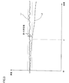
- FIG. 3 is a diagram showing a change in illuminance due to the light 200 being continuously turned on.
- the horizontal axis represents time
- the vertical axis represents the illuminance of the light 200.
- An illuminance change L1 indicated by a solid line indicates an illuminance change when the light 200 is normal.
- the illuminance change L2 indicated by the one-dot chain line indicates the illuminance change when an abnormality is detected while the light 200 is turned on.
- time t0 which is the start of lighting of the light 200
- the illuminance of the light 200 is lu1 for both L1 and L2.
- the illuminance of the light 200 varies slightly due to noise.
- the fluctuation amount of the illuminance of the light 200 from the start of lighting exceeds the first predetermined value, the fluctuation of the illuminance cannot be said to be merely an influence of noise. Detected.
- the first predetermined value a value is set in advance so that fluctuations in illuminance due to noise are not erroneously detected as abnormalities in the light 200.
- Information indicating the first predetermined value is stored in the memory 120, for example.
- the difference D2 between the illuminance indicated by the illuminance change L2 and the illuminance (lu1) at the start of lighting exceeds the first predetermined value. Thereby, the abnormality of the light 200 is detected. That is, according to the abnormality detection apparatus 100, it is possible to detect an abnormality of the light 200 only by monitoring a change in illuminance while the light 200 is lit.
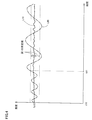
- FIG. 4 is a diagram illustrating another example of a change in illuminance when an abnormality of the light 200 is detected.
- the horizontal axis indicates time
- the vertical axis indicates the illuminance of light 200.
- An illuminance change L10 indicated by a solid line indicates an illuminance change when the light 200 is normal.
- the illuminance change L20 indicated by the alternate long and short dash line indicates the illuminance change when an abnormality is detected while the light 200 is turned on.
- the amplitude of the illuminance change L20 changes greatly compared to the illuminance change L10.
- the illuminance of the light 200 is lu10 for both L10 and L20.
- the difference D2 between the illuminance indicated by the illuminance change L20 and the illuminance at the start of lighting (lu10) exceeds the first predetermined value. Accordingly, an abnormality of the light 200 is detected at the time t11.
- step S170 if it is determined that difference D2 (calculated in step S160) exceeds the first predetermined value (YES in step S170), the failure time of light 200 may be approaching. Since the property is high, the controller 130 detects an abnormality of the light 200 and outputs an abnormality detection signal to the notification unit 300 (step S190).
- step S180 determines whether or not the light 200 is turned off. If it is determined that light 200 is not turned off (NO in step S180), the process proceeds to step S160 again. On the other hand, if it is determined that light 200 has been turned off (YES in step S180), the process returns to the main routine.
- the controller 130 causes the illuminance sensor 110 to detect the illuminance (an example of a physical quantity) detected by the illuminance sensor 110 while the light 200 is turned on and the light 200 is turned off.
- the difference D1 from the detected illuminance falls below the reference illuminance (an example of the reference)
- an abnormality of the light 200 is detected.
- the abnormality of the light 200 can be detected regardless of the time zone and the surrounding environment.
- the controller 130 continuously detects the illuminance (an example of a physical quantity) detected by the illuminance sensor 110 at the start of lighting of the light 200 and the illuminance sensor 110 during the lighting of the light 200.
- An abnormality of the light 200 is detected based on the difference D2 from the detected illuminance. According to this abnormality detection device 100, it is possible to detect an abnormality of the light 200 only by monitoring a change in illuminance while the light 200 is lit.
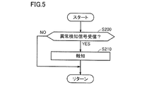
- FIG. 5 is a flowchart showing a notification processing procedure of the notification unit 300.
- the processing shown in this flowchart is performed by main unit (not shown) in notification unit 300 (for example, the controller included in the display when notification unit 300 is a display) during operation of abnormality notification system 10. Called from the routine and executed repeatedly.
- reporting part 300 determines whether the abnormality detection signal was received from the controller 130 (step S200). If it is determined that an abnormality detection signal has not been received (NO in step S200), the process returns to the main routine. On the other hand, when it is determined that the abnormality detection signal has been received (YES in step S200), notification unit 300 performs notification for prompting the user to replace or repair the light 200 (step S210). For example, when the notification unit 300 is a display, the display displays a screen that prompts the user to replace or repair the light 200. Thereafter, the process returns to the main routine.
- the data from which the influence of external light has been removed is used for abnormality detection of the light 200, so the abnormality detection device 100 can be used in the time zone and the surrounding environment. Regardless, it is possible to detect an abnormality of the light 200 and appropriately prompt the user to replace or repair the light 200.
- an abnormality of the light 200 is detected when the difference between the illuminance at the start of lighting of the light 200 and the current illuminance exceeds the first predetermined value even once.
- the abnormality notification system 10 according to the first embodiment, the abnormality of the light 200 can be detected when there is any doubt about the abnormality of the light 200.
- an abnormality of the light 200 is not detected only when the difference between the illuminance at the start of lighting of the light 200 and the current illuminance once exceeds the first predetermined value, and the difference is the first difference.
- the frequency exceeding the predetermined value exceeds the predetermined frequency
- the abnormality of the light 200 is detected.
- the possibility that an abnormality has occurred in the light 200 is increased. Can be detected. Also, erroneous detection due to noise or the like can be prevented.
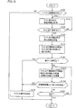
- FIG. 6 is a flowchart showing a processing procedure for detecting an abnormality of the light 200 in the modification of the first embodiment. Referring to FIG. 6, this flowchart is obtained by adding step S175 to the flowchart of FIG. Here, differences from the first embodiment will be mainly described. Note that the processing of the flowchart shown in FIG. 6 is repeatedly executed by being called from a main routine (not shown) in the controller 130 during the operation of the abnormality notification system 10.
- step S170 when it is determined that the difference D2 between the illuminance detected by the illuminance sensor 110 at the start of lighting of the light 200 and the illuminance currently detected by the illuminance sensor 110 exceeds the first predetermined value (YES in step S170). ), The controller 130 determines whether or not the frequency at which the difference D2 exceeds the first predetermined value is equal to or higher than the predetermined frequency (step S175). For example, the controller 130 determines whether or not the number of times that the difference D2 exceeds the first predetermined value in the most recent several cycles is equal to or greater than the predetermined number.
- step S175 If it is determined that the frequency at which the difference D2 exceeds the first predetermined value is greater than or equal to the predetermined frequency (YES in step S175), the controller 130 detects an abnormality of the light 200 and outputs an abnormality detection signal to the notification unit 300. (Step S190). On the other hand, when it is determined that the frequency at which difference D2 exceeds the first predetermined value is less than the predetermined frequency (NO in step S175), the process proceeds to step S180.
- the abnormality of the light 200 is not detected only once the difference D2 exceeds the first predetermined value, and the frequency at which the difference D2 exceeds the first predetermined value is equal to or higher than the predetermined frequency. Only when this happens, the abnormality of the light 200 is detected. Therefore, according to the abnormality detection device 100 according to this modification, it is possible to detect an abnormality of the light 200 after the possibility that an abnormality has occurred in the light 200 is increased.
- Embodiment 2 In Embodiment 1, the example which uses the illumination intensity detected by the illumination intensity sensor 110 as a physical quantity was demonstrated. In the second embodiment, an example will be described in which abnormality of the light 200 is detected using color information detected by the color sensor 110A as a physical quantity.
- FIG. 7 is an overall configuration diagram of an abnormality detection system to which the abnormality detection device according to the second embodiment is applied.
- abnormality notification system 10 ⁇ / b> A includes abnormality detection device 100 ⁇ / b> A instead of abnormality detection device 100 in the first embodiment.
- Other configurations are the same as those in the first embodiment.
- the abnormality detection device 100A detects an abnormality of the light 200.
- the abnormality detection device 100A includes a color sensor 110A, a memory 120A, and a controller 130A.
- the color sensor 110A detects color information (an example of a physical quantity related to the light 200) of light emitted from the light 200.
- the color sensor 110A can also detect the illuminance of the light 200.
- the color information detected by the color sensor 110A is expressed using coordinate information in the L * a * b * color system, for example.
- the color sensor 110A is disposed at a position where the light 200 can be received.
- the memory 120A stores a reference distance (an example of a reference) that serves as a reference for detecting an abnormality of the light 200.
- a reference distance an example of a reference
- the reference distance includes, for example, the coordinates when the new light 200 is turned on and the coordinates when the new light 200 is turned off.
- a value of 80% of the distance (color difference) is set. This reference distance is used to remove the influence of light other than the light 200A from the sensor data of the color sensor 110A, similarly to the reference illuminance in the first embodiment.
- the memory 120A is a non-volatile memory such as a flash memory, for example.
- the controller 130A detects an abnormality of the light 200 based on the color information of the light 200 detected by the color sensor 110A and the reference distance stored in the memory 120A.
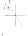
- FIG. 8 is a diagram showing a coordinate space of the L * a * b * color system.
- the L * axis indicates lightness
- the a * axis and b * axis indicate chromaticity (hue and saturation).
- the coordinate C_OFF is an example of coordinates indicated by color information detected by the color sensor 110A while the light 200 is turned off.
- the coordinate C_ON1 is an example of coordinates indicated by color information detected by the color sensor 110A at the start of lighting of the light 200 (immediately after lighting).
- the coordinates C_ON2 and C_ON3 are an example of coordinates indicated by color information detected by the color sensor 110A during continuous lighting of the light 200.
- the coordinates (C_ON1) indicated by the color information detected by the color sensor 110A at the start of lighting of the light 200, and the light 200 being turned off A distance ⁇ from the coordinate (C_OFF) indicated by the color information detected by the color sensor 110A is calculated.
- This distance ⁇ is, for example, the absolute difference between the vector indicated by the color information detected by the color sensor 110A when the light 200 starts to turn on and the vector indicated by the color information detected by the color sensor 110A while the light 200 is turned off. It can also be called a value.
- the calculated distance ⁇ corresponds to a value obtained by removing the influence of light other than the light 200 from the sensor data of the color sensor 110 ⁇ / b> A during lighting of the light 200.
- the abnormality of the light 200 is detected when the calculated distance ⁇ does not fall within the reference range (reference distance ⁇ ⁇ ). That is, in the second embodiment, when the color of light emitted by the light 200 at the start of lighting of the light 200 changes by a predetermined value or more from the new time, an abnormality of the light 200 is detected.
- the influence of light other than the light 200 can be reduced with respect to the abnormality detection of the light 200, so regardless of the time zone and the surrounding environment.
- the abnormality of the light 200 can be detected.
- the coordinates (C_ON2 or C_ON3) indicated by the color information detected by the color sensor 110A while the light 200 is turned on are the color information detected by the color sensor 110A when the light 200 starts to light. It is determined whether or not the object exists in a sphere having a radius r1 centered on the indicated coordinate (C_ON1). That is, in abnormality detection device 100A, it is determined whether the color of light at the start of lighting of light 200 and the current color of light have a predetermined similarity. This is because abnormality detection is performed even when an abnormality occurs in the light 200 during continuous lighting of the light 200.
- the coordinates indicated by the color information of the light 200 slightly fluctuate due to noise, like the illuminance of the light 200 in the first embodiment.
- the coordinates (C_ON1) indicated by the color information detected by the color sensor 110A at the start of lighting of the light 200, and the coordinates (C_ON2 or C_ON3) indicated by the color information currently detected by the color sensor 110A When the distance (distance r) exceeds the first predetermined value (distance r1) (when the distance r does not exist in the sphere having the radius r1), the change in coordinates cannot be said to be merely an influence of noise. An abnormality of the light 200 is detected.
- the first predetermined value is determined in advance such that a change in coordinates due to noise is not erroneously detected as an abnormality of the light 200.
- Information indicating the first predetermined value is stored in advance in memory 120A, for example.
- the first predetermined value is different from the first predetermined value in the first embodiment.
- the distance between the coordinate C_ON1 and the coordinate C_ON2 is smaller than the first predetermined value (distance r1), and thus the abnormality of the light 200 Is not detected.
- the coordinate indicated by the color information currently detected by the color sensor 110A is C_ON3
- the distance between the coordinate C_ON1 and the coordinate C_ON3 exceeds the first predetermined value (distance r1), and thus the abnormality of the light 200 is detected. Detected. That is, according to the abnormality detection device 100A, the abnormality of the light 200 can be detected only by monitoring the change of the color information while the light 200 is lit.
- FIG. 9 is a flowchart showing a processing procedure for detecting an abnormality of the light 200 in the second embodiment.
- this flowchart is common to the flowchart shown in FIG. 2 in some steps.
- steps S110A and S130A to S170A are executed in place of steps S110 and S130 to S170 of FIG. 2 executed in the first embodiment.
- differences from the first embodiment will be mainly described.
- the processing of the flowchart shown in FIG. 9 is repeatedly executed by being called from a main routine (not shown) in the controller 130A during the operation of the abnormality notification system 10A.
- controller 130A detects sensor data (L * a * b *) detected by color sensor 110A while light 200 is turned off. Color information expressed using coordinate information of the color system) is stored in the memory 120A (step S110A).
- step S120 Thereafter, when it is determined in step S120 that the instruction to turn on the light 200 has not been received (NO in step S120), the process proceeds to step S110A again, and the controller 130A is turning off the light 200 stored in the memory 120A. Update the sensor data. On the other hand, if it is determined in step S120 that an instruction to turn on the light 200 has been received (YES in step S120), the controller 130A stores in the memory 120A the color information detected by the color sensor 110A at the start of lighting of the light 200 ( Step S130A).
- the controller 130A accesses the memory 120A, so that the color difference (L *) between the color information detected by the color sensor 110A at the start of lighting of the light 200 and the color information detected by the color sensor 110A while the light 200 is turned off.
- the inter-coordinate distance L1) in the a * b * color system is calculated (step S140A).
- the controller 130A determines whether or not the inter-coordinate distance L1 is within the reference range stored in the memory 120A (step S150A).
- the controller 130A detects an abnormality of the light 200 and outputs an abnormality detection signal to the notification unit 300 (step S190).
- the controller 130A continuously detects whether the light 200 is abnormal while the light 200 is lit. Then, the color difference (inter-coordinate distance L2) between the color information detected by the color sensor 110A at the start of lighting of the light 200 and the color information currently detected by the color sensor 110A is calculated (step S160A).
- controller 130A determines whether or not the inter-coordinate distance L2 exceeds the first predetermined value (step S170A).
- controller 130A detects an abnormality of light 200 and outputs an abnormality detection signal to notification unit 300 (step S190).
- controller 130A determines whether or not light 200 is turned off (step S180). If it is determined that light 200 is not turned off (NO in step S180), the process proceeds to step S160A again. On the other hand, if it is determined that light 200 has been turned off (YES in step S180), the process returns to the main routine.
- the controller 130A causes the color sensor 110A to detect color information (an example of a physical quantity) detected by the color sensor 110A while the light 200 is turned on and to turn off the light 200.
- color information an example of a physical quantity
- the color difference an example of the reference
- an abnormality of the light 200 is detected.
- the abnormality of the light 200 can be detected regardless of the time zone and the surrounding environment.
- the controller 130A continuously detects the color information (an example of a physical quantity) detected by the color sensor 110A at the start of lighting of the light 200 and the color sensor 110A during lighting of the light 200.
- the abnormality of the light 200 is detected based on the color difference (inter-coordinate distance L2) from the color information detected in the above. According to this abnormality detection device 100A, it is possible to detect an abnormality of the light 200 only by monitoring a change in color difference while the light 200 is lit.
- FIG. 10 is a flowchart showing a processing procedure for detecting an abnormality of the light 200 in the modification of the second embodiment. Referring to FIG. 10, this flowchart is obtained by replacing steps S110A and S130A to S150A of the flowchart of FIG. 9 with steps S110 and S130 to A150 of the flowchart of FIG.
- the abnormality detection device 100A according to the modification of the second embodiment, the abnormality of the light 200 can be detected based on the illuminance of the light 200 at the start of lighting of the light 200. The abnormality of the light 200 can be detected based on the above.
- abnormality of light 200 is detected by using illuminance sensor 110.
- abnormality detection device 100A according to the second embodiment abnormality of light 200 is detected by using color sensor 110A.
- abnormality detection device 100B according to the third embodiment both abnormality detection of light 200 using illuminance sensor 110 and abnormality detection of light 200 using color sensor 110A are performed. Since the method for detecting an abnormality of the light 200 using the illuminance sensor 110 and the color sensor 110A is the same as the method for detecting the abnormality of the light 200 in the first and second embodiments, description thereof will not be repeated here.
- the abnormality detection method for the light 200 in the first and second embodiments is employed, if an abnormality occurs in the illuminance sensor 110 or the color sensor 110A, the abnormality in the light 200 cannot be accurately detected. Therefore, in the abnormality detection device 100B according to the third embodiment, in addition to the abnormality detection of the light 200 in the first and second embodiments, the abnormality is detected when an abnormality occurs in the illuminance sensor 110 or the color sensor 110A. To do. The following description will focus on differences from the first and second embodiments.
- FIG. 11 is an overall configuration diagram of an abnormality detection system to which the abnormality detection device according to the third embodiment is applied.
- abnormality notification system 10B includes an abnormality detection device 100B instead of abnormality detection device 100 according to the first embodiment or abnormality detection device 100A according to the second embodiment.
- Other configurations are the same as those in the first and second embodiments.
- the abnormality detection device 100B detects an abnormality of the light 200.
- the abnormality detection device 100B includes an illuminance sensor 110, a color sensor 110A, a memory 120B, and a controller 130B.
- the illuminance sensor 110 detects the illuminance of the light 200.
- the color sensor 110 ⁇ / b> A detects color information of light emitted from the light 200.
- abnormality detection using the illuminance of the light 200 detected by the illuminance sensor 110 and abnormality detection using the color information of the light 200 detected by the color sensor 110A. Both are performed.
- the color sensor 110A can detect illuminance in addition to color information.
- the abnormality of the illuminance sensor 110 or the color sensor 110A is detected by using the illuminance information detected by the color sensor 110A.
- An abnormality detection method of the illuminance sensor 110 or the color sensor 110A will be described in detail later.
- the memory 120B stores a reference illuminance and a reference distance that are used as a reference for detecting an abnormality of the light 200.
- the reference illuminance is used for abnormality detection of the light 200 using the illuminance sensor 110 as in the first embodiment
- the reference distance is used for abnormality detection of the light 200 using the color sensor 110A as in the second embodiment. It is done.
- the controller 130B detects an abnormality of the illuminance sensor 110 or the color sensor 110A using the illuminance detected by the illuminance sensor 110 and the illuminance detected by the color sensor 110A. If both the illuminance sensor 110 and the color sensor 110A are normal, the illuminance detected by the illuminance sensor 110 and the illuminance detected by the color sensor 110A should be substantially the same.
- the controller 130B determines that the illuminance sensor 110 or the color sensor 110A is abnormal when the difference between the illuminance detected by the illuminance sensor 110 and the illuminance detected by the color sensor 110A exceeds a second predetermined value. judge. That is, the controller 130B performs mutual monitoring of the illuminance sensor 110 and the color sensor 110A.
- the second predetermined value for example, a value is set in advance so that a difference in detection result caused by individual differences between the illuminance sensor 110 and the color sensor 110A is not erroneously detected as an abnormality of the illuminance sensor 110 or the color sensor 110A.
- the abnormality detection apparatus 100B the abnormality of the illuminance sensor 110 or the color sensor 110A can be detected.
- a specific processing procedure for detecting an abnormality of the illuminance sensor 110 or the color sensor 110A will be described.
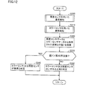
- FIG. 12 is a flowchart illustrating a processing procedure for detecting an abnormality of the illuminance sensor 110 or the color sensor 110A. Referring to FIG. 12, the process shown by this flowchart is repeatedly executed by being called from a main routine (not shown) in controller 130B during operation of abnormality notification system 10B.
- the controller 130B detects an abnormality of the light 200 using the illuminance sensor 110 (step S300). This is the abnormality detection of the light 200 described in the first embodiment. As described above, the illuminance information of the light 200 is acquired in the process of detecting the abnormality of the light 200 using the illuminance sensor 110. In the third embodiment, even if an abnormality of the light 200 is detected in step S300, the process proceeds to step S310 without returning to the main routine.
- the controller 130B detects an abnormality of the light 200 using the color sensor 110A (step S310).
- This is the abnormality detection of the light 200 described in the second embodiment. It is assumed that the illuminance information of the light 200 is acquired in the process of detecting the abnormality of the light 200 using the color sensor 110A.
- the process proceeds to step S320 without returning to the main routine.
- the controller 130B calculates a difference I1 between the illuminance detected by the illuminance sensor 110 in step S300 and the illuminance detected by the color sensor 110A in step S310 (step S320).
- the controller 130B determines whether or not the difference I1 exceeds the above-described second predetermined value (step S330). If it is determined that the difference I1 exceeds the second predetermined value (YES in step S330), the controller 130B can detect the difference between the illuminance sensor 110 and the color sensor 110A. 110 or the color sensor 110A is determined to be abnormal. On the other hand, when it is determined that difference I1 is equal to or smaller than the second predetermined value (NO in step S330), controller 130B determines that both illuminance sensor 110 and color sensor 110A are normal (step S350). Thereafter, the process is returned to the main routine.
- controller 130B determines that the difference between the illuminance detected by illuminance sensor 110 and the illuminance detected by color sensor 110A exceeds the second predetermined value. If it is determined that the illuminance sensor 110 or the color sensor 110A is abnormal. According to this abnormality detection device 100B, an abnormality of the illuminance sensor 110 or the color sensor 110A can be detected, and as a result, an abnormality of the light 200 can be accurately detected.
- Embodiments 1 to 3 As described above, Embodiments 1 to 3 have been described as embodiments of the present invention. However, the present invention is not necessarily limited to the first to third embodiments. Here, an example of another embodiment will be described.
- a predetermined fixed value is used as the reference amount and the first predetermined value.
- the reference amount and the first predetermined value are not necessarily fixed values.
- the reference amount and the first predetermined value may be updated via the Internet.
- the reference amount and the first predetermined value acquired through the Internet are generated using big data.
- a large number of data at the time of the failure of the light 200 in the abnormality notification system 10, 10A is collected through the Internet, and the optimum reference amount and the first predetermined value are sequentially updated based on the collected many data.
- the abnormality notification system 10, 10A can detect the abnormality of the light 200 more accurately by appropriately acquiring the latest reference amount and the first predetermined value.
- 10, 10A, 10B abnormality notification system 100, 100A, 100B abnormality detection device, 110 illuminance sensor, 110A color sensor, 120, 120A, 120B memory, 130, 130A, 130B controller, 200 light, 300 notification unit, 350 system activation Switch, 360 light switch.
Landscapes
- Engineering & Computer Science (AREA)
- Mechanical Engineering (AREA)
- Circuit Arrangement For Electric Light Sources In General (AREA)
Abstract
異常検知装置(100)は、ライト(200)の異常を検知する。異常検知装置(100)は、照度センサ(110)と、メモリ(120)と、コントローラ(130)とを備える。コントローラ(130)は、ライト(200)の点灯中に照度センサ(110)により検知された照度とライト(200)の消灯中に照度センサ(110)により検知された照度との差、及びメモリ(120)に記憶された基準に基づいてライト(200)の異常を検知する。
Description
この発明は、異常検知装置及び報知装置に関し、特に、ライトの異常を検知する異常検知装置及び報知装置に関する。
家庭における照明装置や車両におけるヘッドライト等、世の中には様々なライトが存在する。これらのライトの異常検知は、主に人間の目視によって行なわれている。しかしながら、人間の目視によって、ライト点灯中における光の微妙な変化を認識することは困難である。したがって、人間の目視によって、ライトが故障する前にライトの異常を検知することは難しく、その結果、ライトが故障する前にライトを交換することも難しい。
特開2007-265287号公報(特許文献1)は、LED(Light Emitting Diode)照明の異常を検知する監視システムを開示する。この監視システムは、カメラと、LED照明とを備える。この監視システムによれば、LED照明の発光時にカメラにより撮影される特定文字パターンの輝度を認識することによって、LED照明の異常を検知することができる。
上記特許文献1に開示される監視システムにおいては、ライト(LED照明)の異常を検知するためのカメラ撮影は夜間に行なわれる。したがって、カメラにより撮影される画像の輝度は主にライトの光に依存し、ライト以外の光(たとえば、太陽光)の影響は比較的小さい。
しかしながら、ライトの異常検知は必ずしも特定の時間帯に行なわれるわけではない。時間帯や周囲の環境によっては、ライト以外の光の影響が大きくなる可能性もある。この場合には、上記特許文献1に開示される方法によっては、ライトの異常を正確に検知することができない場合が起こり得る。
この発明は、このような問題を解決するためになされたものであって、その目的は、時間帯や周囲の環境に拘わらず、ライトの異常を検知することができる異常検知装置及び報知装置を提供することである。
この発明のある局面に従う異常検知装置は、ライトの異常を検知する。異常検知装置は、センサと、メモリと、制御部とを備える。センサは、ライトに関する物理量を検知する。メモリは、ライトの異常を検知するための基準を記憶する。制御部は、ライトの点灯中にセンサにより検知された物理量と、ライトの消灯中にセンサにより検知された物理量との差、及び上記基準に基づいてライトの異常を検知する。
ライトの点灯中にセンサにより検知された物理量とライトの消灯中にセンサにより検知された物理量との差は、ライトの点灯中にセンサにより検知された物理量から、ライト以外の光の影響を除去した値に相当する。すなわち、この異常検知装置においては、ライト以外の光の影響を除去した値に応じてライトの異常が検知される。したがって、この異常検知装置によれば、ライトの異常検知に関してライト以外の光の影響を低減することができるため、時間帯や周囲の環境に拘わらず、ライトの異常を検知することができる。
好ましくは、異常検知装置において、センサは、ライトの点灯中に物理量を継続的に検知する。制御部は、ライトの点灯開始時にセンサにより検知された物理量と、ライトの点灯中にセンサにより継続的に検知された物理量との差に基づいてライトの異常を検知する。
より好ましくは、異常検知装置において、制御部は、ライトの点灯開始時にセンサにより検知された物理量と、ライトの点灯中にセンサにより継続的に検知された物理量との差が第1の所定値を上回った場合にライトの異常を検知する。
この異常検知装置においては、ライトの点灯開始時にセンサにより検知された物理量と、ライトの点灯中にセンサにより継続的に検知された物理量との差が第1の所定値を一度でも超えた場合にライトの異常が検知される。したがって、この異常検知装置によれば、ライトの異常に関して少しでも疑いがある場合に、ライトの異常を検知することができる。
より好ましくは、異常検知装置において、制御部は、ライトの点灯開始時にセンサにより検知された物理量と、ライトの点灯中にセンサにより継続的に検知された物理量との差が第1の所定値を上回る頻度が所定頻度を超えた場合にライトの異常を検知する。
この異常検知装置においては、ライトの点灯開始時にセンサにより検知された物理量と、ライトの点灯中にセンサにより継続的に検知された物理量との差が第1の所定値を一度超えただけではライトの異常が検知されず、その頻度が所定頻度を超えた場合に初めてライトの異常が検知される。したがって、この異常検知装置によれば、ライトに異常が生じている可能性が高まってからライトの異常を検知することができる。
好ましくは、異常検知装置において、センサは照度センサであり、物理量は照度である。
好ましくは、異常検知装置において、センサはカラーセンサであり、物理量は色情報である。
この発明の別の局面に従う異常検知装置は、ライトの異常を検知する。異常検知装置は、照度センサと、カラーセンサと、制御部とを備える。照度センサは、ライトの照度を検知する。カラーセンサは、ライトの照度及び色情報を検知する。制御部は、照度センサにより検知された照度又はカラーセンサにより検知された色情報に基づいてライトの異常を検知する。そして、制御部は、照度センサにより検知された照度と、カラーセンサにより検知された照度との差が第2の所定値を上回った場合に照度センサ又はカラーセンサが異常であると判定する。
照度センサ又はカラーセンサを用いてライトの異常を検知する場合、照度センサ又はカラーセンサに異常が生じているとライトの異常を正確に検知することができない。仮に照度センサ及びカラーセンサが正常であるとすると、照度センサにより検知される照度とカラーセンサにより検知される照度とはほぼ同一になるはずである。この異常検知装置においては、照度センサにより検知された照度と、カラーセンサにより検知された照度との差が第2の所定値を超えた場合に照度センサ又はカラーセンサが異常であると判定される。したがって、この異常検知装置によれば、照度センサ又はカラーセンサの異常を検知することができ、結果的に、ライトの異常を正確に検知することができる。
この発明によれば、時間帯や周囲の環境に拘わらず、ライトの異常を検知することができる異常検知装置及び報知装置を提供することができる。
以下、この発明の実施の形態について、図面を参照しながら詳細に説明する。以下では、複数の実施の形態について説明するが、各実施の形態で説明された構成を適宜組み合わせることは出願当初から予定されている。なお、図中同一又は相当部分には同一符号を付してその説明は繰り返さない。
(実施の形態1)
[異常検知システムの全体構成]
図1は、実施の形態1に従う異常検知装置が適用される異常報知システムの全体構成図である。図1を参照して、異常報知システム10は、異常検知装置100と、ライト200と、報知部300と、システム起動スイッチ350と、ライト点灯スイッチ360とを含む。
[異常検知システムの全体構成]
図1は、実施の形態1に従う異常検知装置が適用される異常報知システムの全体構成図である。図1を参照して、異常報知システム10は、異常検知装置100と、ライト200と、報知部300と、システム起動スイッチ350と、ライト点灯スイッチ360とを含む。
異常報知システム10においては、異常検知装置100によってライト200の異常が検知される。ライト200の異常が検知されると、異常検知装置100は、ライト200の交換又は修理をユーザに促すための報知を行なうように報知部300を制御する。異常報知システム10によれば、ユーザは、ライト200の故障前にライト200の交換又は修理の必要性を認識することができる。
ライト200は、不図示の電源から電力の供給を受けることにより発光する光源である。ライト200は、たとえばLED照明や車両のヘッドライト等である。
報知部300は、ライト200の交換又は修理をユーザに促すための報知を行なう。報知部300は、異常検知装置100によってライト200の異常が検知された場合に、異常検知装置100から指示を受けて上記報知を行なう。報知部300は、たとえばディスプレイやスピーカである。たとえば、報知部300がディスプレイである場合には、ライト200の交換又は修理をユーザに促す画面がライト200の異常時にディスプレイに表示される。
システム起動スイッチ350は、異常報知システム10を起動又は停止するためのスイッチである。ユーザは、システム起動スイッチ350を操作することにより、異常報知システム10を起動又は停止することができる。システム起動スイッチ350は、たとえばプッシュ式のスイッチやスライド式のスイッチであってもよい。たとえば異常報知システム10が車両である場合には、システム起動スイッチ350は、車両のスタートスイッチやイグニッションキーであってもよい。
ライト点灯スイッチ360は、ライト200を点灯又は消灯するためのスイッチである。ユーザは、ライト点灯スイッチ360を操作することにより、ライト200を点灯又は消灯することができる。ライト点灯スイッチ360は、たとえばプッシュ式のスイッチやスライド式のスイッチであってもよい。
異常検知装置100は、照度センサ110と、メモリ120と、コントローラ130とを含む。
照度センサ110は、ライト200の照度(ライト200に関する物理量の一例)を検知する。照度センサ110は、ライト200の光を受光できる位置に配置される。
メモリ120は、ライト200の異常を検知するための基準となる基準照度(基準量の一例)を記憶する。基準照度については後程詳しく説明する。メモリ120は、たとえばフラッシュメモリ等の不揮発性メモリである。
コントローラ130は、照度センサ110により検知されたライト200の照度、及び、メモリ120に記憶された基準照度に基づいて、ライト200の異常を検知する。コントローラ130によるライト200の異常検知方法については後程詳しく説明する。
[時間帯や周囲環境に依存しないライト異常検知]
上記のような構成の異常報知システム10において、照度センサ110は、ライト200から発せられる光のみではなく、太陽光等の外光も受光する。したがって、照度センサ110により検知される照度は、ライト200の光及び外光に起因する照度である。ライト200の異常検知が外光の明るさがほぼ同一の状況で常に行なわれるのであれば、単純に照度センサ110により検知される照度を監視することによって、ライト200の異常を検知することができる。
上記のような構成の異常報知システム10において、照度センサ110は、ライト200から発せられる光のみではなく、太陽光等の外光も受光する。したがって、照度センサ110により検知される照度は、ライト200の光及び外光に起因する照度である。ライト200の異常検知が外光の明るさがほぼ同一の状況で常に行なわれるのであれば、単純に照度センサ110により検知される照度を監視することによって、ライト200の異常を検知することができる。
しかしながら、ライト200の異常検知は必ずしも外光の明るさが同一の状況で行なわれるわけではない。時間帯や周囲の環境によっては、外光の影響が大きくなる可能性もある。この場合には、単純に照度センサ110により検知される照度を監視するだけではライト200の異常を検知することができない。
そこで、この実施の形態1に従う異常検知装置100において、コントローラ130は、ライト200の点灯中に照度センサ110により検知された照度とライト200の消灯中に照度センサ110により検知された照度との差、及び基準照度に基づいてライト200の異常を検知する。より具体的には、コントローラ130は、ライト200の点灯中に照度センサ110により検知された照度とライト200の消灯中に照度センサ110により検知された照度との差が基準照度を下回った場合にライト200の異常を検知する。基準照度としては、たとえば、ライト200の新品時の照度(外光の影響なし)の80%の値が設定される。
ライト200の点灯中に照度センサ110により検知された照度と、ライト200の消灯中に照度センサ110により検知された照度との差は、ライト200の点灯中に照度センサ110により検知された照度から、ライト200以外の光の影響を除去した値に相当する。すなわち、この異常検知装置100においては、ライト200以外の光の影響を除去した値が基準照度を下回った場合にライト200の異常が検知される。したがって、この異常検知装置100によれば、ライト200の異常検知に関してライト200以外の光の影響を低減することができるため、時間帯や周囲の環境に拘わらず、ライト200の異常を検知することができる。
[ライト異常検知の処理手順]
図2は、ライト200の異常検知の処理手順を示すフローチャートである。図2を参照して、このフローチャートにより示される処理は、異常報知システム10の作動中にコントローラ130において不図示のメインルーチンから呼び出されて繰り返し実行される。
図2は、ライト200の異常検知の処理手順を示すフローチャートである。図2を参照して、このフローチャートにより示される処理は、異常報知システム10の作動中にコントローラ130において不図示のメインルーチンから呼び出されて繰り返し実行される。
コントローラ130は、システム起動スイッチ350を通じてユーザから異常報知システム10の起動指示を受けたか否かを判定する(ステップS100)。なお、コントローラ130のうち異常報知システム10の起動指示を受けるブロックは、異常報知システム10の停止中にも作動している。
異常報知システム10の起動指示を受けていないと判定されると(ステップS100においてNO)、処理はメインルーチンに戻される。一方、異常報知システム10の起動指示を受けたと判定されると(ステップS100においてYES)、コントローラ130は、ライト200消灯中に照度センサ110で検知されたセンサデータ(照度情報)をメモリ120に記憶させる(ステップS110)。上述の通り、このセンサデータは、ライト200点灯中の照度センサ110のセンサデータに含まれるライト200以外の光の影響を除去するために用いられる。
その後、コントローラ130は、ライト点灯スイッチ360を通じてユーザからライト200の点灯指示を受けたか否かを判定する(ステップS120)。ライト200の点灯指示を受けていないと判定されると(ステップS120においてNO)、処理は再びステップS110に移行し、コントローラ130は、メモリ120に記憶されたライト200消灯中のセンサデータを更新する。
一方、ライト200の点灯指示を受けたと判定されると(ステップS120においてYES)、コントローラ130は、ライト200点灯開始時(ライト200点灯直後)に照度センサ110で検知された照度情報をメモリ120に記憶させる(ステップS130)。なお、照度情報をメモリに記憶させるタイミング(ライト200点灯開始時)は、必ずしもライト200点灯直後である必要はなく、たとえばライト200の点灯開始から所定時間経過後であってもよい。
その後、コントローラ130は、メモリ120にアクセスすることにより、ライト200点灯開始時に照度センサ110で検知された照度と、ライト200消灯中に照度センサ110で検知された照度との差D1を演算する(ステップS140)。具体的には、コントローラ130は、ライト200点灯開始時の照度からライト200消灯中の照度を差し引く演算を実行する。差D1は、ライト200点灯中の照度センサ110のセンサデータからライト200以外の光の影響が除去された値に相当する。
差D1が演算されると、コントローラ130は、差D1がメモリ120に記憶されている基準量(基準照度)を下回っているか否かを判定する(ステップS150)。基準照度は、上述の通り、たとえばライト200の新品時の照度(外光の影響なし)の80%の値である。すなわち、ステップS150においては、ライト200の照度が新品時から所定以上低下しているかが判定されている。
演算された差D1が基準照度を下回っていると判定されると(ステップS150においてYES)、ライト200の故障時期が近づいている可能性が高いため、コントローラ130は、ライト200の異常を検知し、異常検知信号を報知部300に出力する(ステップS190)。異常検知信号を受けた後の報知部300における処理については後程詳しく説明する。
一方、演算された差D1が基準照度以上であると判定されると(ステップS150においてNO)、少なくともライト200の点灯直後の時点においてはライト200に異常が生じていない可能性が高い。この場合には、その後の継続的な点灯中にライト200に異常が生じた時にも異常検知を行なえるようにするために、コントローラ130は、ライト200が消灯されるまでステップS160~S180の処理を繰り返し実行する。
すなわち、コントローラ130は、まず、ライト200点灯開始時に照度センサ110で検知された照度と、照度センサ110で現在検知された照度との差D2(絶対値)を演算する(ステップS160)。具体的には、コントローラ130は、ライト200点灯開始時の照度と現在の照度との差の絶対値を演算する。その後、コントローラ130は、ステップS160において演算された差D2が第1の所定値を上回ったか否かを判定する(ステップS170)。ステップS160,S170における処理の趣旨を次に説明する。
図3は、ライト200が継続的に点灯することによる照度の変化を示す図である。図3を参照して、横軸は時間を示し、縦軸はライト200の照度を示す。実線で示される照度変化L1は、ライト200が正常である場合の照度変化を示す。一方、一点鎖線で示される照度変化L2は、ライト200の点灯中に異常が検知される場合の照度変化を示す。ライト200の点灯開始時である時刻t0において、ライト200の照度は、L1,L2共にlu1である。
照度変化L1の変化からも分かるように、ライト200が正常であったとしても、ライト200の照度はノイズにより多少変動する。この実施の形態1においては、点灯開始時からのライト200の照度の変動量が第1の所定値を上回る場合に、照度の変動が単なるノイズの影響とはいえないため、ライト200の異常が検知される。第1の所定値としては、ノイズによる照度の変動がライト200の異常と誤検知されないような値が予め定められる。第1の所定値を示す情報は、たとえばメモリ120に記憶されている。時刻t1において、照度変化L2が示す照度と点灯開始時の照度(lu1)との差D2は、第1の所定値を上回る。これにより、ライト200の異常が検知される。すなわち、異常検知装置100によれば、ライト200点灯中の照度変化を監視するだけで、ライト200の異常を検知することができる。
なお、ライト200の異常が検知される場合のライト200の照度変化は、図3に示されるような、照度が時間の経過と共に徐々に低下する例に限られない。図4は、ライト200の異常が検知される場合の照度変化の他の一例を示す図である。図4を参照して、横軸は時間を示し、縦軸はライト200の照度を示す。実線で示される照度変化L10は、ライト200が正常である場合の照度変化を示す。一方、一点鎖線で示される照度変化L20は、ライト200の点灯中に異常が検知される場合の照度変化を示す。照度変化L20は、照度変化L10と比較して、振幅が大きく変化する。ライト200の点灯開始時である時刻t10において、ライト200の照度は、L10,L20共にlu10である。そして、時刻t11の時点で、照度変化L20が示す照度と点灯開始時の照度(lu10)との差D2は、第1の所定値を上回る。したがって、時刻t11の時点でライト200の異常が検知される。
再び図2を参照して、ステップS170において、差D2(ステップS160において演算)が第1の所定値を上回ったと判定されると(ステップS170においてYES)、ライト200の故障時期が近づいている可能性が高いため、コントローラ130は、ライト200の異常を検知し、異常検知信号を報知部300に出力する(ステップS190)。
一方、差D2が第1の所定値以下であると判定されると(ステップS170においてNO)、コントローラ130は、ライト200が消灯されたか否かを判定する(ステップS180)。ライト200が消灯されていないと判定されると(ステップS180においてNO)、処理は再びステップS160に移行する。一方、ライト200が消灯されたと判定されると(ステップS180においてYES)、処理はメインルーチンに戻される。
以上のように、実施の形態1に従う異常検知装置100において、コントローラ130は、ライト200の点灯中に照度センサ110により検知された照度(物理量の一例)とライト200の消灯中に照度センサ110により検知された照度との差D1が基準照度(基準の一例)を下回った場合にライト200の異常を検知する。この異常検知装置100によれば、時間帯や周囲の環境に拘わらず、ライト200の異常を検知することができる。
また、実施の形態1に従う異常検知装置100において、コントローラ130は、ライト200の点灯開始時に照度センサ110により検知された照度(物理量の一例)とライト200の点灯中に照度センサ110により継続的に検知された照度との差D2に基づいてライト200の異常を検知する。この異常検知装置100によれば、ライト200の点灯中の照度変化を監視するだけでライト200の異常を検知することができる。
[報知処理手順]
図5は、報知部300の報知処理手順を示すフローチャートである。図5を参照して、このフローチャートに示される処理は、異常報知システム10の作動中に報知部300(たとえば報知部300がディスプレイである場合には、ディスプレイに含まれるコントローラ)において不図示のメインルーチンから呼び出されて繰り返し実行される。
図5は、報知部300の報知処理手順を示すフローチャートである。図5を参照して、このフローチャートに示される処理は、異常報知システム10の作動中に報知部300(たとえば報知部300がディスプレイである場合には、ディスプレイに含まれるコントローラ)において不図示のメインルーチンから呼び出されて繰り返し実行される。
報知部300は、コントローラ130から異常検知信号を受信したか否かを判定する(ステップS200)。異常検知信号を受信していないと判定されると(ステップS200においてNO)、処理はメインルーチンに戻る。一方、異常検知信号を受信したと判定されると(ステップS200においてYES)、報知部300は、ライト200の交換又は修理をユーザに促すための報知を行なう(ステップS210)。たとえば報知部300がディスプレイである場合には、ディスプレイは、ライト200の交換又は修理をユーザに促す画面を表示する。その後、処理はメインルーチンに戻る。
以上のように、この実施の形態1に従う異常報知システム10においては、外光の影響を除去したデータがライト200の異常検知に用いられるため、異常検知装置100は、時間帯や周囲の環境に拘わらず、ライト200の異常を検知し、ライト200の交換又は修理をユーザに適切に促すことができる。
(実施の形態1の変形例)
実施の形態1においては、図2のステップS170,S190で、ライト200点灯開始時の照度と現在の照度との差が一度でも第1の所定値を超えるとライト200の異常が検知された。これにより、実施の形態1に従う異常報知システム10によれば、ライト200の異常に関して少しでも疑いがある場合に、ライト200の異常を検知することができる。
実施の形態1においては、図2のステップS170,S190で、ライト200点灯開始時の照度と現在の照度との差が一度でも第1の所定値を超えるとライト200の異常が検知された。これにより、実施の形態1に従う異常報知システム10によれば、ライト200の異常に関して少しでも疑いがある場合に、ライト200の異常を検知することができる。
この実施の形態1の変形例においては、ライト200点灯開始時の照度と現在の照度との差が第1の所定値を一度超えただけではライト200の異常が検知されず、差が第1の所定値を超える頻度が所定頻度を超えた場合にライト200の異常が検知される。この変形例に従う異常検知装置100によれば、差が第1の所定値を一度超えただけではライト200の異常が検知されないため、ライト200に異常が生じている可能性が高まってからライト200の異常を検知することができる。また、ノイズ等による誤検出も防止することができる。
図6は、実施の形態1の変形例におけるライト200の異常検知の処理手順を示すフローチャートである。図6を参照して、このフローチャートは、図2のフローチャートに対してステップS175の処理を加えたものである。ここでは、主に実施の形態1と異なる点について説明する。なお、図6に示されるフローチャートの処理は、異常報知システム10の作動中にコントローラ130において不図示のメインルーチンから呼び出されて繰り返し実行される。
ステップS170において、ライト200点灯開始時に照度センサ110で検知された照度と、照度センサ110で現在検知された照度との差D2が第1の所定値を上回ったと判定されると(ステップS170においてYES)、コントローラ130は、差D2が第1の所定値を上回る頻度が所定頻度以上か否かを判定する(ステップS175)。たとえば、コントローラ130は、直近の数サイクルにおいて差D2が第1の所定値を上回った回数が所定回数以上か否かを判定する。
差D2が第1の所定値を上回る頻度が所定頻度以上であると判定されると(ステップS175においてYES)、コントローラ130は、ライト200の異常を検知し、異常検知信号を報知部300に出力する(ステップS190)。一方、差D2が第1の所定値を上回る頻度が所定頻度未満であると判定されると(ステップS175においてNO)、処理はステップS180に移行する。
この変形例に従う異常検知装置100においては、差D2が第1の所定値を一度超えただけではライト200の異常が検知されず、差D2が第1の所定値を上回る頻度が所定頻度以上となった場合にのみライト200の異常が検知される。したがって、この変形例に従う異常検知装置100によれば、ライト200に異常が生じている可能性が高まってからライト200の異常を検知することができる。
(実施の形態2)
実施の形態1においては、物理量として照度センサ110で検知される照度を用いる例について説明した。実施の形態2においては、物理量としてカラーセンサ110Aで検知される色情報を用いて、ライト200の異常を検知する例について説明する。
実施の形態1においては、物理量として照度センサ110で検知される照度を用いる例について説明した。実施の形態2においては、物理量としてカラーセンサ110Aで検知される色情報を用いて、ライト200の異常を検知する例について説明する。
[異常検知システムの全体構成]
図7は、実施の形態2に従う異常検知装置が適用される異常検知システムの全体構成図である。図7を参照して、異常報知システム10Aは、実施の形態1における異常検知装置100に代えて、異常検知装置100Aを含む。他の構成については、実施の形態1と同様である。
図7は、実施の形態2に従う異常検知装置が適用される異常検知システムの全体構成図である。図7を参照して、異常報知システム10Aは、実施の形態1における異常検知装置100に代えて、異常検知装置100Aを含む。他の構成については、実施の形態1と同様である。
異常検知装置100Aは、ライト200の異常を検知する。異常検知装置100Aは、カラーセンサ110Aと、メモリ120Aと、コントローラ130Aとを含む。
カラーセンサ110Aは、ライト200から発せられる光の色情報(ライト200に関する物理量の一例)を検知する。また、カラーセンサ110Aは、ライト200の照度も検知することができる。カラーセンサ110Aにより検知される色情報は、たとえばL*a*b*表色系における座標情報を用いて表現される。カラーセンサ110Aは、ライト200の光を受光できる位置に配置される。
メモリ120Aは、ライト200の異常を検知するための基準となる基準距離(基準の一例)を記憶する。たとえば、色情報がL*a*b*表色系の座標情報を用いて表現される場合、基準距離には、たとえば、新品のライト200点灯時の座標と新品のライト200消灯時の座標との距離(色差)の80%の値が設定される。この基準距離は、実施の形態1における基準照度と同様、カラーセンサ110Aのセンサデータからライト200A以外の光の影響を除去するために用いられる。メモリ120Aは、たとえばフラッシュメモリ等の不揮発性メモリである。
コントローラ130Aは、カラーセンサ110Aにより検知されたライト200の光の色情報、及び、メモリ120Aに記憶された基準距離に基づいて、ライト200の異常を検知する。
[カラーセンサを用いたライト異常検知]
図8は、L*a*b*表色系の座標空間を示す図である。図8を参照して、L*軸は明度を示し、a*軸及びb*軸は色度(色相及び彩度)を示す。座標C_OFFは、ライト200消灯中にカラーセンサ110Aにより検知される色情報が示す座標の一例である。座標C_ON1は、ライト200の点灯開始時(点灯直後)にカラーセンサ110Aにより検知される色情報が示す座標の一例である。座標C_ON2及びC_ON3は、ライト200の継続的な点灯中にカラーセンサ110Aにより検知される色情報が示す座標の一例である。
図8は、L*a*b*表色系の座標空間を示す図である。図8を参照して、L*軸は明度を示し、a*軸及びb*軸は色度(色相及び彩度)を示す。座標C_OFFは、ライト200消灯中にカラーセンサ110Aにより検知される色情報が示す座標の一例である。座標C_ON1は、ライト200の点灯開始時(点灯直後)にカラーセンサ110Aにより検知される色情報が示す座標の一例である。座標C_ON2及びC_ON3は、ライト200の継続的な点灯中にカラーセンサ110Aにより検知される色情報が示す座標の一例である。
実施の形態2に従う異常検知装置100Aにおいては、ライト200の異常を検知するために、ライト200の点灯開始時にカラーセンサ110Aにより検知された色情報が示す座標(C_ON1)と、ライト200の消灯中にカラーセンサ110Aにより検知された色情報が示す座標(C_OFF)との距離Δが演算される。この距離Δは、たとえば、ライト200の点灯開始時にカラーセンサ110Aにより検知された色情報が示すベクトルと、ライト200の消灯中にカラーセンサ110Aにより検知された色情報が示すベクトルとの差の絶対値ということもできる。演算された距離Δは、ライト200点灯中のカラーセンサ110Aのセンサデータからライト200以外の光の影響が除去された値に相当する。
実施の形態2においては、演算された距離Δが基準範囲(基準距離±α)に収まらない場合に、ライト200の異常が検知される。すなわち、この実施の形態2においては、ライト200の点灯開始時にライト200により発せられる光の色が新品時から所定以上変化した場合に、ライト200の異常が検知される。
異常検知装置100Aによれば、実施の形態1に従う異常検知装置100と同様、ライト200の異常検知に関してライト200以外の光の影響を低減することができるため、時間帯や周囲の環境に拘わらず、ライト200の異常を検知することができる。
また、異常検知装置100Aにおいては、ライト200の点灯中にカラーセンサ110Aにより検知される色情報が示す座標(C_ON2又はC_ON3)が、ライト200の点灯開始時にカラーセンサ110Aにより検知された色情報が示す座標(C_ON1)を中心とする半径r1の球内に存在するか否かが判定される。すなわち、異常検知装置100Aにおいては、ライト200点灯開始時の光の色と、現在の光の色とが所定の類似度を有するか否かが判定される。これは、ライト200の継続的な点灯中にライト200に異常が生じた時にも異常検知を行なうためである。
ライト200が正常であったとしても、実施の形態1におけるライト200の照度と同様、ライト200の色情報が示す座標はノイズにより多少変動する。この実施の形態2においては、ライト200の点灯開始時にカラーセンサ110Aにより検知された色情報が示す座標(C_ON1)と、カラーセンサ110Aにより現在検知された色情報が示す座標(C_ON2又はC_ON3)との距離(距離r)が第1の所定値(距離r1)を上回った場合(距離rが半径r1の球内に存在しない場合)に、座標の変動が単なるノイズの影響とはいえないため、ライト200の異常が検知される。第1の所定値としては、ノイズによる座標の変動がライト200の異常と誤検知されないような値が予め定められる。第1の所定値を示す情報は、たとえばメモリ120Aに予め記憶されている。なお、第1の所定値は、実施の形態1における第1の所定値とは異なるものである。
たとえば、カラーセンサ110Aにより現在検知された色情報が示す座標がC_ON2である場合には、座標C_ON1と座標C_ON2との距離が第1の所定値(距離r1)よりも小さいため、ライト200の異常は検知されない。一方、カラーセンサ110Aにより現在検知された色情報が示す座標がC_ON3である場合には、座標C_ON1と座標C_ON3との距離が第1の所定値(距離r1)を上回るため、ライト200の異常が検知される。すなわち、異常検知装置100Aによれば、ライト200点灯中の色情報の変化を監視するだけで、ライト200の異常を検知することができる。
[ライト異常検知の処理手順]
図9は、実施の形態2における、ライト200の異常検知の処理手順を示すフローチャートである。図9を参照して、このフローチャートは、一部のステップにおいて、図2に示されるフローチャートと共通する。実施の形態2においては、実施の形態1において実行された図2のステップS110,S130~S170に代えて、ステップS110A,S130A~S170Aがそれぞれ実行される。ここでは、主に実施の形態1と異なる点について説明する。なお、図9に示されるフローチャートの処理は、異常報知システム10Aの作動中にコントローラ130Aにおいて不図示のメインルーチンから呼び出されて繰り返し実行される。
図9は、実施の形態2における、ライト200の異常検知の処理手順を示すフローチャートである。図9を参照して、このフローチャートは、一部のステップにおいて、図2に示されるフローチャートと共通する。実施の形態2においては、実施の形態1において実行された図2のステップS110,S130~S170に代えて、ステップS110A,S130A~S170Aがそれぞれ実行される。ここでは、主に実施の形態1と異なる点について説明する。なお、図9に示されるフローチャートの処理は、異常報知システム10Aの作動中にコントローラ130Aにおいて不図示のメインルーチンから呼び出されて繰り返し実行される。
ステップS100において、異常報知システム10Aの起動指示を受けたと判定されると(ステップS100においてYES)、コントローラ130Aは、ライト200消灯中にカラーセンサ110Aで検知されたセンサデータ(L*a*b*表色系の座標情報を用いて表現される色情報)をメモリ120Aに記憶させる(ステップS110A)。
その後、ステップS120において、ライト200の点灯指示を受けていないと判定されると(ステップS120においてNO)、処理は再びステップS110Aに移行し、コントローラ130Aは、メモリ120Aに記憶されたライト200消灯中のセンサデータを更新する。一方、ステップS120において、ライト200の点灯指示を受けたと判定されると(ステップS120においてYES)、コントローラ130Aは、ライト200点灯開始時にカラーセンサ110Aで検知された色情報をメモリ120Aに記憶させる(ステップS130A)。
そして、コントローラ130Aは、メモリ120Aにアクセスすることにより、ライト200点灯開始時にカラーセンサ110Aで検知された色情報と、ライト200消灯中にカラーセンサ110Aで検知された色情報との色差(L*a*b*表色系における座標間距離L1)を演算する(ステップS140A)。座標間距離L1が演算されると、コントローラ130Aは、座標間距離L1がメモリ120Aに記憶される基準範囲に収まっているか否かを判定する(ステップS150A)。
座標間距離L1が基準範囲に収まっていないと判定されると(ステップS150AにおいてNO)、コントローラ130Aは、ライト200の異常を検知し、異常検知信号を報知部300に出力する(ステップS190)。一方、座標間距離L1が基準範囲に収まっていると判定されると(ステップS150AにおいてYES)、コントローラ130Aは、ライト200点灯中にライト200に異常が生じないかを継続的に検知するために、ライト200点灯開始時にカラーセンサ110Aで検知された色情報と、カラーセンサ110Aで現在検知された色情報との色差(座標間距離L2)を演算する(ステップS160A)。
その後、コントローラ130Aは、座標間距離L2が第1の所定値を上回ったか否かを判定する(ステップS170A)。座標間距離L2が第1の所定値を上回ったと判定されると(ステップS170AにおいてYES)、コントローラ130Aは、ライト200の異常を検知し、異常検知信号を報知部300に出力する(ステップS190)。一方、演算された差が第1の所定値以下であると判定されると(ステップS170AにおいてNO)、コントローラ130Aは、ライト200が消灯されたか否かを判定する(ステップS180)。ライト200が消灯されていないと判定されると(ステップS180においてNO)、処理は再びステップS160Aに移行する。一方、ライト200が消灯されたと判定されると(ステップS180においてYES)、処理はメインルーチンに戻される。
以上のように、実施の形態2に従う異常検知装置100Aにおいて、コントローラ130Aは、ライト200の点灯中にカラーセンサ110Aにより検知された色情報(物理量の一例)とライト200の消灯中にカラーセンサ110Aにより検知された色情報との色差(座標間距離L1)が基準範囲(基準の一例)に収まらない場合にライト200の異常を検知する。この異常検知装置100Aによれば、時間帯や周囲の環境に拘わらず、ライト200の異常を検知することができる。
また、実施の形態2に従う異常検知装置100Aにおいて、コントローラ130Aは、ライト200の点灯開始時にカラーセンサ110Aにより検知された色情報(物理量の一例)とライト200の点灯中にカラーセンサ110Aにより継続的に検知された色情報との色差(座標間距離L2)に基づいてライト200の異常を検知する。この異常検知装置100Aによれば、ライト200の点灯中の色差変化を監視するだけでライト200の異常を検知することができる。
(実施の形態2の変形例)
実施の形態2においては、ライト200の点灯開始時(点灯直後)の異常検知(図9のステップS100~S150Aに対応)、及び、ライト200点灯中の異常検知(図9のステップS160A~S180に対応)の両方の異常検知において色情報が用いられた。この実施の形態2の変形例においては、ライト200の点灯中の異常検知においては色情報が用いられるが、ライト200の点灯開始時の異常検知においてはライト200の照度(実施の形態1に対応)が用いられる。
実施の形態2においては、ライト200の点灯開始時(点灯直後)の異常検知(図9のステップS100~S150Aに対応)、及び、ライト200点灯中の異常検知(図9のステップS160A~S180に対応)の両方の異常検知において色情報が用いられた。この実施の形態2の変形例においては、ライト200の点灯中の異常検知においては色情報が用いられるが、ライト200の点灯開始時の異常検知においてはライト200の照度(実施の形態1に対応)が用いられる。
図10は、実施の形態2の変形例におけるライト200の異常検知の処理手順を示すフローチャートである。図10を参照して、このフローチャートは、図9のフローチャートのステップS110A,S130A~S150Aを図2のフローチャートのステップS110,S130~A150にそれぞれ置き換えたものである。この実施の形態2の変形例に従う異常検知装置100Aによれば、ライト200の点灯開始時にはライト200の照度に基づいてライト200の異常を検知することができ、ライト200の点灯中には色差変化に基づいてライト200の異常を検知することができる。
(実施の形態3)
実施の形態1に従う異常検知装置100においては、照度センサ110を用いることによって、ライト200の異常が検知された。実施の形態2に従う異常検知装置100Aにおいては、カラーセンサ110Aを用いることによって、ライト200の異常が検知された。この実施の形態3に従う異常検知装置100Bにおいては、照度センサ110を用いたライト200の異常検知と、カラーセンサ110Aを用いたライト200の異常検知との両方が行なわれる。照度センサ110,カラーセンサ110Aを用いたライト200の異常検知の方法は、実施の形態1,2におけるライト200の異常検知の方法とそれぞれ同様であるため、ここでは説明を繰り返さない。
実施の形態1に従う異常検知装置100においては、照度センサ110を用いることによって、ライト200の異常が検知された。実施の形態2に従う異常検知装置100Aにおいては、カラーセンサ110Aを用いることによって、ライト200の異常が検知された。この実施の形態3に従う異常検知装置100Bにおいては、照度センサ110を用いたライト200の異常検知と、カラーセンサ110Aを用いたライト200の異常検知との両方が行なわれる。照度センサ110,カラーセンサ110Aを用いたライト200の異常検知の方法は、実施の形態1,2におけるライト200の異常検知の方法とそれぞれ同様であるため、ここでは説明を繰り返さない。
実施の形態1,2におけるライト200の異常検知方法を採用した場合、照度センサ110又はカラーセンサ110Aに異常が生じるとライト200の異常を正確に検知することができない。そこで、この実施の形態3に従う異常検知装置100Bにおいては、実施の形態1,2におけるライト200の異常検知に加えて、照度センサ110又はカラーセンサ110Aに異常が生じた場合に、その異常を検知する。以下、実施の形態1,2と異なる点を中心に説明する。
[報知装置の全体構成]
図11は、実施の形態3に従う異常検知装置が適用される異常検知システムの全体構成図である。図11を参照して、異常報知システム10Bは、実施の形態1に従う異常検知装置100又は実施の形態2に従う異常検知装置100Aに代えて、異常検知装置100Bを含む。他の構成については、実施の形態1,2と同様である。
図11は、実施の形態3に従う異常検知装置が適用される異常検知システムの全体構成図である。図11を参照して、異常報知システム10Bは、実施の形態1に従う異常検知装置100又は実施の形態2に従う異常検知装置100Aに代えて、異常検知装置100Bを含む。他の構成については、実施の形態1,2と同様である。
異常検知装置100Bは、ライト200の異常を検知する。異常検知装置100Bは、照度センサ110と、カラーセンサ110Aと、メモリ120Bと、コントローラ130Bとを含む。
照度センサ110は、ライト200の照度を検知する。カラーセンサ110Aは、ライト200から発せられる光の色情報を検知する。上述のように、この実施の形態3においては、照度センサ110により検知されるライト200の照度を用いた異常検知と、カラーセンサ110Aにより検知されるライト200の光の色情報を用いた異常検知との両方が行なわれる。
カラーセンサ110Aは、色情報の他に照度も検知することができる。この実施の形態3においては、カラーセンサ110Aにより検知された照度の情報を用いることによって照度センサ110又はカラーセンサ110Aの異常が検知される。照度センサ110又はカラーセンサ110Aの異常検知方法については後程詳しく説明する。
メモリ120Bは、ライト200の異常を検知するための基準となる基準照度及び基準距離を記憶する。基準照度は、実施の形態1と同様に照度センサ110を用いたライト200の異常検知に用いられ、基準距離は、実施の形態2と同様にカラーセンサ110Aを用いたライト200の異常検知に用いられる。
コントローラ130Bは、照度センサ110により検知された照度と、カラーセンサ110Aにより検知された照度とを用いて照度センサ110又はカラーセンサ110Aの異常を検知する。仮に照度センサ110及びカラーセンサ110Aの双方が正常であるとすると、照度センサ110により検知される照度とカラーセンサ110Aにより検知される照度とはほぼ同一になるはずである。
そこで、コントローラ130Bは、照度センサ110により検知された照度と、カラーセンサ110Aにより検知された照度との差が第2の所定値を上回った場合に照度センサ110又はカラーセンサ110Aが異常であると判定する。すなわち、コントローラ130Bは、照度センサ110及びカラーセンサ110Aの相互監視を行なう。なお、第2の所定値としては、たとえば照度センサ110及びカラーセンサ110Aの個体差等により生じる検知結果の違いが照度センサ110又はカラーセンサ110Aの異常と誤検知されないような値が予め定められる。
これにより、異常検知装置100Bによれば、照度センサ110又はカラーセンサ110Aの異常を検知することができる。次に、照度センサ110又はカラーセンサ110Aの異常検知の具体的処理手順について説明する。
[照度センサ又はカラーセンサの異常検知処理手順]
図12は、照度センサ110又はカラーセンサ110Aの異常検知の処理手順を示すフローチャートである。図12を参照して、このフローチャートにより示される処理は、異常報知システム10Bの作動中にコントローラ130Bにおいて不図示のメインルーチンから呼び出されて繰り返し実行される。
図12は、照度センサ110又はカラーセンサ110Aの異常検知の処理手順を示すフローチャートである。図12を参照して、このフローチャートにより示される処理は、異常報知システム10Bの作動中にコントローラ130Bにおいて不図示のメインルーチンから呼び出されて繰り返し実行される。
コントローラ130Bは、照度センサ110を用いたライト200の異常検知を行なう(ステップS300)。これは、実施の形態1において説明したライト200の異常検知である。上述の通り、照度センサ110を用いたライト200の異常検知の過程で、ライト200の照度情報が取得される。なお、この実施の形態3においては、ステップS300においてライト200の異常が検知されたとしても、処理はメインルーチンに戻らずにステップS310に移行する。
その後、コントローラ130Bは、カラーセンサ110Aを用いてライト200の異常検知を行なう(ステップS310)。これは、実施の形態2において説明したライト200の異常検知である。カラーセンサ110Aを用いたライト200の異常検知の過程で、ライト200の照度情報が取得されるものとする。なお、この実施の形態3においては、ステップS300においてライト200の異常が検知されたとしても、処理はメインルーチンに戻らずにステップS320に移行する。
コントローラ130Bは、ステップS300において照度センサ110により検知された照度と、ステップS310においてカラーセンサ110Aにより検知された照度との差I1を演算する(ステップS320)。
そして、コントローラ130Bは、差I1が上述の第2の所定値を上回ったか否かを判定する(ステップS330)。差I1が第2の所定値を上回ったと判定されると(ステップS330においてYES)、差I1が照度センサ110及びカラーセンサ110Aの個体差等によるものとはいえないため、コントローラ130Bは、照度センサ110又はカラーセンサ110Aに異常が生じていると判定する。一方、差I1が第2の所定値以下であると判定されると(ステップS330においてNO)、コントローラ130Bは、照度センサ110及びカラーセンサ110Aの両方が正常であると判定する(ステップS350)。その後、処理はメインルーチンに戻される。
以上のように、この実施の形態3に従う異常検知装置100Bにおいて、コントローラ130Bは、照度センサ110により検知された照度と、カラーセンサ110Aにより検知された照度との差が第2の所定値を上回った場合に照度センサ110又はカラーセンサ110Aが異常であると判定する。この異常検知装置100Bによれば、照度センサ110又はカラーセンサ110Aの異常を検知することができ、結果的に、ライト200の異常を正確に検知することができる。
(他の実施の形態)
以上のように、この発明の実施の形態として実施の形態1~3を説明した。しかしながら、この発明は必ずしもこの実施の形態1~3に限定されない。ここでは、他の実施の形態の一例について説明する。
以上のように、この発明の実施の形態として実施の形態1~3を説明した。しかしながら、この発明は必ずしもこの実施の形態1~3に限定されない。ここでは、他の実施の形態の一例について説明する。
実施の形態1,2において、基準量及び第1の所定値としては、予め定められた固定値が用いられることとした。しかしながら、基準量及び第1の所定値は、必ずしも固定値としなくてもよい。たとえば、インターネットを通じて基準量及び第1の所定値が更新されるような構成としてもよい。たとえば、インターネットを通じて取得される基準量及び第1の所定値は、ビッグデータを用いて生成される。異常報知システム10,10Aにおけるライト200故障時の多数のデータがインターネットを通じて収集され、収集された多数のデータに基づいて最適な基準量及び第1の所定値が順次更新される。異常報知システム10,10Aは、適宜、最新の基準量及び第1の所定値を取得することで、より正確にライト200の異常を検知することができる。
今回開示された実施の形態はすべての点で例示であって制限的なものではないと考えられるべきである。本発明の範囲は上記した説明ではなく、請求の範囲によって示され、請求の範囲と均等の意味および範囲内でのすべての変更が含まれることが意図される。
10,10A,10B 異常報知システム、100,100A,100B 異常検知装置、110 照度センサ、110A カラーセンサ、120,120A,120B メモリ、130,130A,130B コントローラ、200 ライト、300 報知部、350 システム起動スイッチ、360 ライト点灯スイッチ。
Claims (9)
- ライトの異常を検知する異常検知装置であって、
前記ライトに関する物理量を検知するセンサと、
前記異常を検知するための基準を記憶するメモリと、
前記ライトの点灯中に前記センサにより検知された物理量と、前記ライトの消灯中に前記センサにより検知された物理量との差、及び前記基準に基づいて前記異常を検知する制御部とを備える、異常検知装置。 - 前記センサは、前記ライトの点灯中に前記物理量を継続的に検知し、
前記制御部は、前記ライトの点灯開始時に前記センサにより検知された物理量と、前記ライトの点灯中に前記センサにより継続的に検知された物理量との差に基づいて前記異常を検知する、請求項1に記載の異常検知装置。 - 前記制御部は、前記ライトの点灯開始時に前記センサにより検知された物理量と、前記ライトの点灯中に前記センサにより継続的に検知された物理量との差が第1の所定値を上回った場合に前記異常を検知する、請求項2に記載の異常検知装置。
- 前記制御部は、前記ライトの点灯開始時に前記センサにより検知された物理量と、前記ライトの点灯中に前記センサにより継続的に検知された物理量との差が第1の所定値を上回る頻度が所定頻度を超えた場合に前記異常を検知する、請求項2に記載の異常検知装置。
- 前記センサは照度センサであり、前記物理量は照度である、請求項1~4のいずれか1項に記載の異常検知装置。
- 前記センサはカラーセンサであり、前記物理量は色情報である、請求項1~4のいずれか1項に記載の異常検知装置。
- 前記請求項1~6のいずれか1項に記載の異常検知装置と、
前記ライトの交換又は修理をユーザに促すための報知を行なう報知部とを備え、
前記報知部は、前記制御部により前記異常が検知されるのに応じて前記報知を行なう、報知装置。 - ライトの異常を検知する異常検知装置であって、
前記ライトの点灯中に、前記ライトに関する物理量を継続的に検知するセンサと、
前記ライトの点灯開始時に前記センサにより検知された物理量と、前記ライトの点灯中に前記センサにより継続的に検知された物理量との差に基づいて前記異常を検知する制御部とを備える、異常検知装置。 - ライトの異常を検知する異常検知装置であって、
前記ライトの照度を検知する照度センサと、
前記ライトの照度及び色情報を検知するカラーセンサと、
前記照度センサにより検知された照度又は前記カラーセンサにより検知された色情報に基づいて前記ライトの異常を検知する制御部とを備え、
前記制御部は、前記照度センサにより検知された照度と、前記カラーセンサにより検知された照度との差が第2の所定値を上回った場合に前記照度センサ又は前記カラーセンサが異常であると判定する、異常検知装置。
Priority Applications (2)
| Application Number | Priority Date | Filing Date | Title |
|---|---|---|---|
| JP2018519189A JP6905517B2 (ja) | 2016-05-24 | 2017-05-12 | 異常検知装置及び報知装置 |
| US16/095,794 US10493915B2 (en) | 2016-05-24 | 2017-05-12 | Abnormality detection apparatus and notification apparatus |
Applications Claiming Priority (2)
| Application Number | Priority Date | Filing Date | Title |
|---|---|---|---|
| JP2016-103280 | 2016-05-24 | ||
| JP2016103280 | 2016-05-24 |
Publications (1)
| Publication Number | Publication Date |
|---|---|
| WO2017204005A1 true WO2017204005A1 (ja) | 2017-11-30 |
Family
ID=60411240
Family Applications (1)
| Application Number | Title | Priority Date | Filing Date |
|---|---|---|---|
| PCT/JP2017/018001 Ceased WO2017204005A1 (ja) | 2016-05-24 | 2017-05-12 | 異常検知装置及び報知装置 |
Country Status (3)
| Country | Link |
|---|---|
| US (1) | US10493915B2 (ja) |
| JP (1) | JP6905517B2 (ja) |
| WO (1) | WO2017204005A1 (ja) |
Families Citing this family (4)
| Publication number | Priority date | Publication date | Assignee | Title |
|---|---|---|---|---|
| US11383641B2 (en) * | 2018-11-28 | 2022-07-12 | Honda Motor Co., Ltd. | System and method for a remote vehicle light check |
| US11479175B2 (en) * | 2019-06-21 | 2022-10-25 | Grote Industries, Llc | Error detection system and method in a vehicle lighting system |
| CN114222413B (zh) * | 2021-12-22 | 2023-09-12 | 惠州祺瑞电工有限公司 | 一种照明系统的故障自检方法及照明系统 |
| CN116653770B (zh) * | 2023-07-27 | 2023-11-21 | 浙江省标准化研究院(金砖国家标准化(浙江)研究中心、浙江省物品编码中心) | 一种道路机动车用光源安全评估预警系统 |
Citations (7)
| Publication number | Priority date | Publication date | Assignee | Title |
|---|---|---|---|---|
| JPH03211426A (ja) * | 1990-01-17 | 1991-09-17 | Nippondenso Co Ltd | 輝度検出装置 |
| JP2001338782A (ja) * | 2000-03-23 | 2001-12-07 | Olympus Optical Co Ltd | 照明用光源装置 |
| JP2009252394A (ja) * | 2008-04-02 | 2009-10-29 | Sharp Corp | 太陽電池照明装置 |
| JP2010200985A (ja) * | 2009-03-04 | 2010-09-16 | Oiwa Machinery Corp | ショーケースの照明方法及び照明装置 |
| JP2012113909A (ja) * | 2010-11-24 | 2012-06-14 | Panasonic Corp | 照明器具 |
| JP2012177576A (ja) * | 2011-02-25 | 2012-09-13 | Denso Corp | 光検出装置 |
| JP2016058240A (ja) * | 2014-09-10 | 2016-04-21 | パナソニックIpマネジメント株式会社 | 発光素子点灯装置、発光モジュール、および照明装置 |
Family Cites Families (7)
| Publication number | Priority date | Publication date | Assignee | Title |
|---|---|---|---|---|
| DE19852351A1 (de) * | 1998-11-13 | 2000-05-18 | Hella Kg Hueck & Co | Diagnosesystem für eine LED-Leuchte in einem Kraftfahrzeug |
| JP2007265287A (ja) | 2006-03-29 | 2007-10-11 | Fujitsu Ltd | 照明の劣化による画像認識精度低下を軽減する方法、装置およびシステム |
| CN101408297B (zh) * | 2007-10-12 | 2010-06-02 | 富准精密工业(深圳)有限公司 | 可远程监控的发光二极管灯具及其远程监控方法 |
| US9552438B2 (en) * | 2013-05-17 | 2017-01-24 | Paypal, Inc. | Systems and methods for responsive web page delivery based on network bandwidth |
| US11324089B2 (en) * | 2014-02-25 | 2022-05-03 | Lumenetix, Llc | Color mixing model provisioning for light-emitting diode-based lamps |
| WO2016051537A1 (ja) * | 2014-09-30 | 2016-04-07 | Necディスプレイソリューションズ株式会社 | 照明装置、ホイール劣化検出方法及びプロジェクタ |
| JP6643645B2 (ja) * | 2015-02-17 | 2020-02-12 | スタンレー電気株式会社 | 車両用灯具 |
-
2017
- 2017-05-12 JP JP2018519189A patent/JP6905517B2/ja active Active
- 2017-05-12 US US16/095,794 patent/US10493915B2/en active Active
- 2017-05-12 WO PCT/JP2017/018001 patent/WO2017204005A1/ja not_active Ceased
Patent Citations (7)
| Publication number | Priority date | Publication date | Assignee | Title |
|---|---|---|---|---|
| JPH03211426A (ja) * | 1990-01-17 | 1991-09-17 | Nippondenso Co Ltd | 輝度検出装置 |
| JP2001338782A (ja) * | 2000-03-23 | 2001-12-07 | Olympus Optical Co Ltd | 照明用光源装置 |
| JP2009252394A (ja) * | 2008-04-02 | 2009-10-29 | Sharp Corp | 太陽電池照明装置 |
| JP2010200985A (ja) * | 2009-03-04 | 2010-09-16 | Oiwa Machinery Corp | ショーケースの照明方法及び照明装置 |
| JP2012113909A (ja) * | 2010-11-24 | 2012-06-14 | Panasonic Corp | 照明器具 |
| JP2012177576A (ja) * | 2011-02-25 | 2012-09-13 | Denso Corp | 光検出装置 |
| JP2016058240A (ja) * | 2014-09-10 | 2016-04-21 | パナソニックIpマネジメント株式会社 | 発光素子点灯装置、発光モジュール、および照明装置 |
Also Published As
| Publication number | Publication date |
|---|---|
| JP6905517B2 (ja) | 2021-07-21 |
| US10493915B2 (en) | 2019-12-03 |
| US20190126822A1 (en) | 2019-05-02 |
| JPWO2017204005A1 (ja) | 2019-03-22 |
Similar Documents
| Publication | Publication Date | Title |
|---|---|---|
| JP5615862B2 (ja) | 車両周囲監視装置 | |
| JP4853160B2 (ja) | 車両検出装置及びヘッドランプ制御装置 | |
| US10421389B2 (en) | Vehicle lighting system | |
| JP6905517B2 (ja) | 異常検知装置及び報知装置 | |
| US20220289101A1 (en) | Vehicle detecting device, vehicle lamp system, vehicle detecting method, light distribution controlling device, and light distribution controlling method | |
| WO2018092709A1 (ja) | 撮像装置状態監視装置、撮像装置状態監視方法、およびプログラム | |
| JP6228492B2 (ja) | 車外環境認識装置 | |
| JP7517334B2 (ja) | ヘッドアップディスプレイ装置 | |
| JP6259335B2 (ja) | 車外環境認識装置 | |
| JP2011121490A (ja) | 車両用前照灯制御装置 | |
| JP7176447B2 (ja) | ライト監視装置 | |
| JP6740916B2 (ja) | 運転支援システム、運転支援方法 | |
| JP2014000908A (ja) | 光源状態検知装置、光源状態検知方法、及び光源状態検知プログラム | |
| JP2006082653A (ja) | ランプ点灯状態検出装置 | |
| US11231642B2 (en) | Light source module, projector using the same and light source control method | |
| CN117325755A (zh) | 车辆日间行车灯的控制方法、存储介质、控制装置及车辆 | |
| WO2017154356A1 (ja) | 視線検出装置および視線検出方法 | |
| JP2023552187A (ja) | 非幻惑性照明機能を用いる照明システムを制御するための方法 | |
| JP2016088281A (ja) | 操作入力装置 | |
| JP7725947B2 (ja) | オブジェクト認識制御装置およびオブジェクト認識制御方法 | |
| CN112954861A (zh) | 照明装置及照明装置及照明系统的运作方法 | |
| JP6248061B2 (ja) | ライト制御システムおよびライト制御装置 | |
| CN121486677A (zh) | 车用监控系统 | |
| JP6425953B2 (ja) | 車両用前照灯システムの制御方法 | |
| JP2015020625A (ja) | 車両後方照明システム |
Legal Events
| Date | Code | Title | Description |
|---|---|---|---|
| WWE | Wipo information: entry into national phase |
Ref document number: 2018519189 Country of ref document: JP |
|
| NENP | Non-entry into the national phase |
Ref country code: DE |
|
| 121 | Ep: the epo has been informed by wipo that ep was designated in this application |
Ref document number: 17802599 Country of ref document: EP Kind code of ref document: A1 |
|
| 122 | Ep: pct application non-entry in european phase |
Ref document number: 17802599 Country of ref document: EP Kind code of ref document: A1 |