WO2017203880A1 - 軸受、および、過給機 - Google Patents
軸受、および、過給機 Download PDFInfo
- Publication number
- WO2017203880A1 WO2017203880A1 PCT/JP2017/015101 JP2017015101W WO2017203880A1 WO 2017203880 A1 WO2017203880 A1 WO 2017203880A1 JP 2017015101 W JP2017015101 W JP 2017015101W WO 2017203880 A1 WO2017203880 A1 WO 2017203880A1
- Authority
- WO
- WIPO (PCT)
- Prior art keywords
- bearing
- arc
- shaft
- insertion hole
- peripheral surface
- Prior art date
- Legal status (The legal status is an assumption and is not a legal conclusion. Google has not performed a legal analysis and makes no representation as to the accuracy of the status listed.)
- Ceased
Links
Images





Classifications
-
- F—MECHANICAL ENGINEERING; LIGHTING; HEATING; WEAPONS; BLASTING
- F16—ENGINEERING ELEMENTS AND UNITS; GENERAL MEASURES FOR PRODUCING AND MAINTAINING EFFECTIVE FUNCTIONING OF MACHINES OR INSTALLATIONS; THERMAL INSULATION IN GENERAL
- F16C—SHAFTS; FLEXIBLE SHAFTS; ELEMENTS OR CRANKSHAFT MECHANISMS; ROTARY BODIES OTHER THAN GEARING ELEMENTS; BEARINGS
- F16C17/00—Sliding-contact bearings for exclusively rotary movement
- F16C17/02—Sliding-contact bearings for exclusively rotary movement for radial load only
- F16C17/028—Sliding-contact bearings for exclusively rotary movement for radial load only with fixed wedges to generate hydrodynamic pressure, e.g. multi-lobe bearings
-
- F—MECHANICAL ENGINEERING; LIGHTING; HEATING; WEAPONS; BLASTING
- F02—COMBUSTION ENGINES; HOT-GAS OR COMBUSTION-PRODUCT ENGINE PLANTS
- F02B—INTERNAL-COMBUSTION PISTON ENGINES; COMBUSTION ENGINES IN GENERAL
- F02B39/00—Component parts, details, or accessories relating to, driven charging or scavenging pumps, not provided for in groups F02B33/00 - F02B37/00
-
- F—MECHANICAL ENGINEERING; LIGHTING; HEATING; WEAPONS; BLASTING
- F02—COMBUSTION ENGINES; HOT-GAS OR COMBUSTION-PRODUCT ENGINE PLANTS
- F02B—INTERNAL-COMBUSTION PISTON ENGINES; COMBUSTION ENGINES IN GENERAL
- F02B39/00—Component parts, details, or accessories relating to, driven charging or scavenging pumps, not provided for in groups F02B33/00 - F02B37/00
- F02B39/14—Lubrication of pumps; Safety measures therefor
-
- F—MECHANICAL ENGINEERING; LIGHTING; HEATING; WEAPONS; BLASTING
- F16—ENGINEERING ELEMENTS AND UNITS; GENERAL MEASURES FOR PRODUCING AND MAINTAINING EFFECTIVE FUNCTIONING OF MACHINES OR INSTALLATIONS; THERMAL INSULATION IN GENERAL
- F16C—SHAFTS; FLEXIBLE SHAFTS; ELEMENTS OR CRANKSHAFT MECHANISMS; ROTARY BODIES OTHER THAN GEARING ELEMENTS; BEARINGS
- F16C17/00—Sliding-contact bearings for exclusively rotary movement
- F16C17/10—Sliding-contact bearings for exclusively rotary movement for both radial and axial load
-
- F—MECHANICAL ENGINEERING; LIGHTING; HEATING; WEAPONS; BLASTING
- F16—ENGINEERING ELEMENTS AND UNITS; GENERAL MEASURES FOR PRODUCING AND MAINTAINING EFFECTIVE FUNCTIONING OF MACHINES OR INSTALLATIONS; THERMAL INSULATION IN GENERAL
- F16C—SHAFTS; FLEXIBLE SHAFTS; ELEMENTS OR CRANKSHAFT MECHANISMS; ROTARY BODIES OTHER THAN GEARING ELEMENTS; BEARINGS
- F16C33/00—Parts of bearings; Special methods for making bearings or parts thereof
- F16C33/02—Parts of sliding-contact bearings
- F16C33/04—Brasses; Bushes; Linings
- F16C33/06—Sliding surface mainly made of metal
- F16C33/10—Construction relative to lubrication
- F16C33/1025—Construction relative to lubrication with liquid, e.g. oil, as lubricant
- F16C33/106—Details of distribution or circulation inside the bearings, e.g. details of the bearing surfaces to affect flow or pressure of the liquid
- F16C33/1075—Wedges, e.g. ramps or lobes, for generating pressure
-
- F—MECHANICAL ENGINEERING; LIGHTING; HEATING; WEAPONS; BLASTING
- F16—ENGINEERING ELEMENTS AND UNITS; GENERAL MEASURES FOR PRODUCING AND MAINTAINING EFFECTIVE FUNCTIONING OF MACHINES OR INSTALLATIONS; THERMAL INSULATION IN GENERAL
- F16C—SHAFTS; FLEXIBLE SHAFTS; ELEMENTS OR CRANKSHAFT MECHANISMS; ROTARY BODIES OTHER THAN GEARING ELEMENTS; BEARINGS
- F16C2360/00—Engines or pumps
- F16C2360/23—Gas turbine engines
- F16C2360/24—Turbochargers
-
- F—MECHANICAL ENGINEERING; LIGHTING; HEATING; WEAPONS; BLASTING
- F16—ENGINEERING ELEMENTS AND UNITS; GENERAL MEASURES FOR PRODUCING AND MAINTAINING EFFECTIVE FUNCTIONING OF MACHINES OR INSTALLATIONS; THERMAL INSULATION IN GENERAL
- F16C—SHAFTS; FLEXIBLE SHAFTS; ELEMENTS OR CRANKSHAFT MECHANISMS; ROTARY BODIES OTHER THAN GEARING ELEMENTS; BEARINGS
- F16C27/00—Elastic or yielding bearings or bearing supports, for exclusively rotary movement
- F16C27/02—Sliding-contact bearings
Definitions
- the present disclosure relates to a bearing that supports a shaft and a supercharger including the same.
- a turbocharger in which a shaft is rotatably supported by a bearing housing is known.
- a turbine impeller is provided at one end of the shaft.
- a compressor impeller is provided at the other end of the shaft.
- the supercharger is connected to the engine.
- the turbine impeller is rotated by the exhaust gas discharged from the engine.
- the rotation of the turbine impeller causes the compressor impeller to rotate through the shaft.
- the supercharger compresses air as the compressor impeller rotates and sends the compressed air to the engine.
- Patent Document 1 describes a bearing having a bearing surface in which a circular arc surface is continuous in a waveform on the outer side and the inner side of a virtual inner diameter surface.
- An object of the present disclosure is to provide a bearing and a supercharger that can improve rotational stability.
- a bearing in order to solve the above problem, includes an insertion hole through which a shaft is inserted, a bearing surface formed on an inner peripheral surface of the insertion hole, a bearing surface, In the cross section perpendicular to the central axis, the positions of the centers of curvature are different from each other on the inside of the bearing surface, and are formed on the bearing surface and a plurality of arc portions that are arc surfaces that are spaced apart in the rotation direction of the shaft.
- the curvature radius of the arc portion may be smaller than the minimum distance from the central axis to the bearing surface.
- An annular main body formed with an insertion hole, two bearing surfaces provided in the inner peripheral surface of the insertion hole so as to be separated from each other in the central axis direction, and penetrating from the inner peripheral surface of the main body portion to the outer peripheral surface. You may provide the oil hole opened between two bearing surfaces.
- a supercharger according to an aspect of the present disclosure includes the bearing.
- FIG. 4 is a partial extraction diagram of FIG. 3. It is the figure which inserted the shaft in the insertion hole of FIG.
- FIG. 6A is a first view for explaining a method of processing a bearing surface.
- FIG. 6B is a second view for explaining the bearing surface machining method.
- FIG. 6C is a third view for explaining the bearing surface processing method. It is explanatory drawing for demonstrating a 1st modification.
- FIG. 9A is a first view for explaining another processing method of the bearing surface.
- FIG. 9B is a second view for explaining another processing method of the bearing surface. It is explanatory drawing for demonstrating a 2nd modification. It is a partial extraction figure of FIG.
- FIG. 1 is a schematic sectional view of the supercharger C.
- the direction of the arrow L shown in FIG. An arrow R direction shown in FIG. 1 will be described as the right side of the supercharger C.
- the supercharger C includes a supercharger main body 1.
- the supercharger main body 1 includes a bearing housing 2.
- a turbine housing 4 is connected to the left side of the bearing housing 2 by a fastening mechanism 3.
- a compressor housing 6 is connected to the right side of the bearing housing 2 by fastening bolts 5.
- the bearing housing 2, the turbine housing 4, and the compressor housing 6 are integrated.
- a protrusion 2 a is provided on the outer peripheral surface of the bearing housing 2.
- the protrusion 2 a is provided in the vicinity of the turbine housing 4.
- the protrusion 2 a protrudes in the radial direction of the bearing housing 2.
- a projection 4 a is provided on the outer peripheral surface of the turbine housing 4.
- the protrusion 4 a is provided in the vicinity of the bearing housing 2.
- the protrusion 4 a protrudes in the radial direction of the turbine housing 4.
- the bearing housing 2 and the turbine housing 4 are attached by band-fastening the protrusions 2 a and 4 a by the fastening mechanism 3.
- the fastening mechanism 3 is configured by, for example, a G coupling that holds the protrusions 2a and 4a.
- the bearing housing 2 has a bearing hole 2b.
- the bearing hole 2b penetrates the supercharger C in the left-right direction.
- a bearing 7 (a semi-floating bearing is shown as an example in FIG. 1) is provided in the bearing hole 2b.
- a shaft 8 is rotatably supported by the bearing 7.
- a turbine impeller 9 is provided at the left end of the shaft 8.
- a turbine impeller 9 is rotatably accommodated in the turbine housing 4.
- a compressor impeller 10 is provided at the right end of the shaft 8. The compressor impeller 10 is rotatably accommodated in the compressor housing 6.
- the compressor housing 6 has an intake port 11 formed therein.
- the intake port 11 opens on the right side of the supercharger C.
- the intake port 11 is connected to an air cleaner (not shown).
- the diffuser flow path 12 is formed.
- the diffuser flow path 12 is formed by facing surfaces of the bearing housing 2 and the compressor housing 6.
- the diffuser flow path 12 pressurizes air.
- the diffuser flow path 12 is formed in an annular shape from the radially inner side to the outer side of the shaft 8.
- the diffuser flow path 12 communicates with the intake port 11 via the compressor impeller 10 on the radially inner side.
- the compressor housing 6 is provided with a compressor scroll passage 13.
- the compressor scroll channel 13 is annular.
- the compressor scroll flow path 13 is located, for example, on the outer side in the radial direction of the shaft 8 than the diffuser flow path 12.
- the compressor scroll passage 13 communicates with an intake port of an engine (not shown).
- the compressor scroll channel 13 also communicates with the diffuser channel 12. Therefore, when the compressor impeller 10 rotates, air is taken into the compressor housing 6 from the intake port 11. The sucked air is accelerated by the action of centrifugal force in the process of flowing between the blades of the compressor impeller 10. The increased air is pressurized in the diffuser flow path 12 and the compressor scroll flow path 13. The pressurized air is guided to the intake port of the engine.
- a discharge port 14 is formed in the turbine housing 4.
- the discharge port 14 opens on the left side of the supercharger C.
- the discharge port 14 is connected to an exhaust gas purification device (not shown).
- the turbine housing 4 is provided with a flow path 15 and a turbine scroll flow path 16.
- the turbine scroll channel 16 is annular.
- the turbine scroll flow path 16 is located, for example, on the radially outer side of the turbine impeller 9 than the flow path 15.
- the turbine scroll passage 16 communicates with the gas inlet. Exhaust gas discharged from an exhaust manifold (not shown) of the engine is guided to the gas inlet.
- the turbine scroll passage 16 communicates with the turbine impeller 9 via the passage 15. Therefore, the exhaust gas guided from the gas inlet to the turbine scroll passage 16 is guided to the discharge port 14 via the passage 15 and the turbine impeller 9.
- the exhaust gas guided to the discharge port 14 rotates the turbine impeller 9 in the flow process.
- the rotational force of the turbine impeller 9 is transmitted to the compressor impeller 10 via the shaft 8.
- the air is boosted by the rotational force of the compressor impeller 10 and guided to the intake port of the engine.
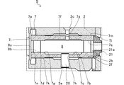
- FIG. 2 is a diagram in which a one-dot chain line portion of FIG. 1 is extracted.
- a bearing structure S is provided inside the bearing housing 2.
- the shaft 8 and the bearing 7 are disposed, for example, in a direction inclined or orthogonal to the vertical direction.
- the lubricating oil flows from the oil passage 2c formed in the bearing housing 2 into the bearing hole 2b.
- a bearing 7 is disposed in the bearing hole 2b.
- An insertion hole 7 b is formed in the main body portion 7 a of the bearing 7.
- the insertion hole 7b penetrates in the axial direction of the shaft 8 (hereinafter simply referred to as the axial direction).
- a shaft 8 is provided in the insertion hole 7b.
- Two bearing surfaces 7d and 7e are formed on the inner peripheral surface 7c of the insertion hole 7b. The two bearing surfaces 7 d and 7 e are separated in the axial direction of the shaft 8.
- the lubricating oil spreads left and right in FIG. 2 from the oil hole 7g and is supplied to the gap between the shaft 8 and the bearing surfaces 7d and 7e.
- the shaft 8 is pivotally supported by the oil film pressure of the lubricating oil supplied to the gap between the shaft 8 and the bearing surfaces 7d and 7e.
- the main body portion 7a is provided with a through hole 7h that penetrates from the inner peripheral surface 7c to the outer peripheral surface 7f.
- a pin hole 2e is formed in the bearing housing 2 at a portion facing the through hole 7h.
- the pin hole 2e passes through a wall portion that forms the bearing hole 2b, and the positioning pin 20 is press-fitted into the pin hole 2e from the lower side in FIG.
- the tip of the positioning pin 20 is inserted into the through hole 7h of the bearing 7, and the rotation of the bearing 7 and the movement in the axial direction are restricted.
- an oil draining member 21 is attached to the shaft 8 on the right side (compressor impeller 10 side) in FIG. 2 with respect to the main body portion 7a.
- the oil draining member 21 is an annular member.
- the oil draining member 21 scatters the lubricating oil flowing to the compressor impeller 10 side through the shaft 8 to the outside in the radial direction.
- the oil draining member 21 suppresses leakage of the lubricating oil to the compressor impeller 10 side.
- the oil draining member 21 is opposed to the main body portion 7a in the axial direction.
- the outer diameter of the surface 21a facing the main body 7a is larger than the inner diameter of the bearing surface 7e and smaller than the outer diameter of the main body 7a.
- the shaft 8 is provided with a large diameter portion 8a.
- the outer diameter of the large diameter portion 8a is larger than the inner diameter of the bearing surface 7d of the main body portion 7a.
- the outer diameter of the large diameter part 8a is larger than the outer diameter of the main body part 7a, for example.
- the large diameter portion 8a is located on the left side (turbine impeller 9 side) in FIG. 2 with respect to the main body portion 7a.
- the large diameter portion 8a is opposed to the main body portion 7a in the axial direction.
- Damper portions 7k and 7m are formed on both end sides in the axial direction on the outer peripheral surface of the main body portion 7a.
- the damper portions 7k and 7m suppress the vibration of the shaft 8 by the oil film pressure of the lubricating oil supplied to the gap with the inner peripheral surface 2f of the bearing hole 2b.
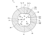
- FIG. 3 is an explanatory diagram for explaining the bearing surface 7d, and a cross section perpendicular to the axial direction of the shaft 8 (of the insertion hole 7b) of a portion of the main body portion 7a of the bearing 7 where the bearing surface 7d is formed. (Cross section perpendicular to the central axis O).
- the bearing surface 7 d has a plurality of (for example, four in this embodiment) arc portions 30.
- the center of curvature A is located inside the bearing surface 7 d (insertion hole 7 b) (on the center axis O side from the bearing surface 7 d).
- the plurality of arc portions 30 are different from each other in the position of the center of curvature A.
- the plurality of arc portions 30 are spaced apart from each other in the rotation direction of the shaft 8 (the circumferential direction of the outer peripheral surface 7f of the main body portion 7a).
- the position of the center of curvature A and the radius of curvature of the arc portion 30 can be arbitrarily set so that the connecting surface 31 described later is connected in the common tangential direction of the adjacent arc surfaces 33.
- the position of the arc portion 30 is determined. For example, if the positions of the centers of curvature A are arranged at equal intervals on a concentric circle centered on the central axis O and the curvature radii are set to be the same, the position of the arc portion 30 is the rotation of the shaft 8 as shown in FIG. They are separated at equal intervals in the direction (the circumferential direction of the outer peripheral surface 7f of the main body 7a).
- the position of the curvature center A may be arranged at unequal intervals. Further, the position of the curvature center A may be arranged on a non-concentric circle. Moreover, the magnitude
- a connecting surface 31 is formed between the arc portions 30.
- the connection surface 31 connects the adjacent arc portions 30.
- the connection surface 31 is formed continuously to one end 30 a of one adjacent arc portion 30 and the other end 30 b of the other arc portion 30.
- the intermediate portion 31c between the one end 31a and the other end 31b that is continuous with the arc portion 30 has a minimum distance La from the central axis O of the insertion hole 7b that is the smallest of the bearing surfaces 7d. Yes.
- the radius of curvature Ra of the arc portion 30 is smaller than the minimum distance La.
- the arc portion 30 and the connection surface 31 extend from one end 7n in the axial direction to the other end 7p (see FIG. 2) of the bearing surface 7d.
- a portion of the shaft 8 that is pivotally supported by the bearing surface 7d is referred to as a pivoted portion 8b (see FIG. 2).
- the connection surface 31 may not extend from one end 7n in the axial direction to the other end 7p (see FIG. 2) of the bearing surface 7d.
- the connection surface 31 may extend over the entire length in the axial direction to a portion of the bearing surface 7d that faces the shaft support portion 8b in the radial direction.
- connection surface 31 extends over the entire length in the axial direction to a portion of the bearing surface 7d facing the shaft support 8b of the shaft 8 in the radial direction. It does not exist and may extend only to a part in the axial direction.
- the preload coefficient of the bearing is Cp (see FIG. 5) for the maximum distance between the arc portion 30 and the shaft 8, and Cb (see FIG. 5) for the minimum distance between the intermediate portion 31c of the connection surface 31 and the shaft 8. Then, it is represented by 1- (Cb / Cp).
- FIG. 4 is a partial extraction diagram of FIG.
- the connection point X between the arc portion 30 and the connection surface 31, that is, the one end 30a and the other end 30b of the arc portion 30 and the one end 31a and the other end 31b of the connection surface 31 are positioned on a common tangent line Vb indicated by a one-dot chain line in FIG. is doing.
- the common tangent line Vb is a tangent line that touches both of two virtual arcs Va drawn by extending two adjacent arc portions 30.
- a connection point X between the arc portion 30 and the connection surface 31 is at the same position as the common tangent line Vb of the two virtual arcs Va and the contact point Y between the virtual arcs Va.
- the length of the connection surface 31 is equal to the distance between two adjacent contacts Y.
- connection surface 31 is a tangent (tangential plane) at the connection point X of the arc portion 30. Further, the connection surface 31 is located on the common tangent line Vb.
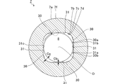
- FIG. 5 shows the shaft 8 inserted through the insertion hole 7b shown in FIG.
- the bearing surface 7 d is closest to the shaft 8 in the intermediate portion 31 c of the connection surface 31.
- the vicinity of the gap between the intermediate portion 31c and the shaft 8 (indicated by a broken circle in FIG. 5) has a generally wedge shape.
- a wedge effect is exhibited as the shaft 8 rotates.
- the lubricating oil that rotates around the rotation of the shaft 8 presses the shaft 8 radially inward (in the radial direction). That is, a radial load is supported.
- a wedge-shaped gap is formed for each of a plurality of (preferably three or more, for example, four in this embodiment) intermediate portions 31c.
- the wedge effect by a plurality of wedge shapes is exhibited.
- the shaft 8 is pressed radially inward from a plurality of directions.
- the shaft 8 can be supported in a stable manner.
- the intermediate portions 31c may be arranged at equal intervals in the circumferential direction.
- the weight of the rotating body including the shaft 8 is relatively small. In this case, the influence of the weight of the rotating body is small. Therefore, when the shaft 8 is pressed radially inward in the circumferential direction around the axis, the shaft 8 can be supported more stably.
- connection point X between the arc portion 30 and the connection surface 31 is at the same position as the contact Y between the common tangent line Vb and the virtual arc Va. Therefore, a part of the connection surface 31 does not protrude toward the shaft 8 side. Stability can be improved.
- FIG. 6 (a) is a first diagram for explaining a processing method of the bearing surface 7d.
- FIG. 6B is a second view for explaining the processing method of the bearing surface 7d.
- FIG. 6C is a third diagram for explaining the processing method of the bearing surface 7d.
- the lower hole 32 having the central axis O of the insertion hole 7b as the central axis is formed.
- the radius Rb of the lower hole 32 is smaller than the minimum distance La (or equal to the minimum distance La).
- an arc surface 33 having a center of curvature A and a radius of curvature Ra is formed.
- connection surface 31 and the circular arc part 30 are formed.
- the radius of curvature Ra of the arc surface 33 (arc portion 30) is smaller than the minimum distance La. From this, the processing of the arc surface 33 can be easily performed with a tool having a radius equal to the curvature radius Ra, for example. Processing cost can be reduced.
- multi-arc bearings can improve the stability by increasing the preload coefficient as compared to perfect circle bearings.
- the preload coefficient can be increased and the stability can be improved by simpler processing than the known multi-arc bearing.
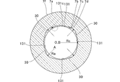
- FIG. 7 is an explanatory diagram for explaining the first modification.
- the connection surface 131 is an arc surface.
- the connection surface 131 is an arc surface.
- the position of the center of curvature B of the connection surface 131 is inside the bearing surface 7d.
- the curvature centers B of the plurality of connection surfaces 131 are all at the same position as the central axis O of the insertion hole 7b.
- FIG. 8 is a partial extraction diagram of FIG.
- the connection point X between the arc portion 30 and the connection surface 131 is at the same position as the common tangent line Vb of the two virtual arcs Va and the contact point Y of the virtual arc Va, as in the above-described embodiment.
- the length of the connection surface 131 is longer than the separation distance between two adjacent connection points X (that is, the separation distance between two adjacent contact points Y).
- the vicinity of the gap between the intermediate portion 131c of the connection surface 131 and the shaft 8 (indicated by a broken circle in FIG. 7) is generally wedge-shaped. It has become.
- the shaft 8 can be stably supported by the wedge effect.
- connection surface 131 is an arc surface
- the connection surface 131 is processed with a tool having a radius equal to the curvature radius Rc of the connection surface 131, for example. It can be done easily. Therefore, the processing cost is reduced.
- the center of curvature B of the connection surface 131 is at the same position as the central axis O of the insertion hole 7b, a plurality of connection surfaces 131 can be processed simultaneously. Processing costs are further reduced.
- FIG. 9A is a first view for explaining another processing method of the bearing surface 7d.
- FIG. 9B is a second view for explaining another processing method of the bearing surface 7d.
- the lower hole 132 having the central axis O of the insertion hole 7b as the central axis is formed.
- the radius Rd of the lower hole 132 is equal to the radius of curvature Rc of the connection surface 131.
- an arc portion 30 having a curvature radius Ra is formed.
- the center of curvature A of the arc portion 30 has the same distance from the central axis O of the insertion hole 7b.
- the plurality of arc portions 30 are located at equal intervals in the circumferential direction of the outer peripheral surface 7f. Thus, the arc portion 30 and the connection surface 131 are formed.
- the processing of the lower hole 132 and the processing of the connection surface 131 are performed simultaneously. Man-hours can be reduced and processing costs can be reduced.
- FIG. 10 is an explanatory diagram for explaining a second modification.
- the arc portion 230 has a central angle of less than 90 degrees.
- the connection surface 231 is a plane.
- the connection surface 231 may be an arc surface similar to that of the first modification described above.
- FIG. 11 is a partial extraction diagram of FIG.
- the connection surface 231 is located closer to the central axis O than the common tangent line Vb of the two virtual arcs Va.
- the connection point X between the arc portion 230 and the connection surface 231 is located closer to the center 230c on the arc portion 230 than the common tangent line Vb of the two virtual arcs Va and the contact point Y of the virtual arc Va. That is, the connection point X between the arc portion 230 and the connection surface 231 is located on the side away from the two adjacent contacts Y on the virtual arc Va.
- connection point X between the arc portion 230 and the connection surface 231 is located in a direction away from the other contact Y with respect to one contact Y. Further, the length of the connection surface 231 is longer than the separation distance between two adjacent contacts Y.
- connection surfaces 131 and 231 do not protrude toward the shaft 8 side, and the stability can be improved.
- the preload coefficient can be increased and the stability can be improved by simpler processing than known multi-arc bearings.
- the bearing surface 7d has been described.
- the bearing surface 7e has the same shape, and the stability of supporting the shaft 8 can be improved as in the bearing surface 7d. Processing costs can be reduced.
- the oil passage 2 c is provided between the bearing surface 7 d and the bearing surface 7 e in the axial direction of the shaft 8. Then, the case where the lubricating oil supplied from the oil passage 2c to the bearing hole 2b spreads to the left and right through the oil hole 7g corresponding to the oil passage 2c and is supplied to the bearing surface 7d and the bearing surface 7e will be described. did.
- the method of lubricating the bearing is not limited to this.
- a plurality of oil passages or branched oil passages may be provided in the bearing housing 2 as in the configuration described in FIG. 2 of JP-A-2014-51898.
- the oil path may each open to the position corresponding to both the bearing surface 7d and the bearing surface 7e among the bearing holes 2b.
- oil holes penetrating from the inner peripheral surface of the bearing to the outer peripheral surface can be provided in the main body portion of the bearing.
- the lubricating oil is supplied from the oil passage to the bearing outer peripheral surfaces (damper portions 7k and 7m). Part of the lubricating oil supplied to the bearing outer peripheral surface is supplied to the bearing inner peripheral surfaces (bearing surfaces 7d and 7e) through the oil holes.
- the bearing 7 is not limited to a semi-floating bearing and may be an arbitrary sliding bearing.
- the disclosed shape may be applied to a full floating bearing instead of a semi-floating bearing.
- the disclosed shape can be applied to one or both of the bearing inner circumferential surface and the bearing hole 2b inner circumferential surface.
- the bearing rotates at about half the speed of the shaft.
- the shaft rotates relative to the full floating bearing.
- the full floating bearing rotates with respect to the bearing hole 2b. Accordingly, the wedge effect can be exerted on the inner peripheral side and the outer peripheral side of the bearing as in the embodiment and the modification of the present disclosure. For this reason, it is possible to improve the rotational stability by increasing the preload coefficient by simpler processing than the known multi-arc bearing.
- the body portion 7a of the bearing 7 extends from the bearing surface 7d to the bearing surface 7e and is integrally formed has been described.
- the main body 7a may be divided in the axial direction into a part having the bearing surface 7d and a part having the bearing surface 7e.
- the present disclosure can be used for a bearing that supports a shaft and a supercharger including the bearing.
Landscapes
- Engineering & Computer Science (AREA)
- General Engineering & Computer Science (AREA)
- Mechanical Engineering (AREA)
- Chemical & Material Sciences (AREA)
- Combustion & Propulsion (AREA)
- Physics & Mathematics (AREA)
- Fluid Mechanics (AREA)
- Oil, Petroleum & Natural Gas (AREA)
- Supercharger (AREA)
- Sliding-Contact Bearings (AREA)
Abstract
軸受7は、シャフトが挿通される挿通孔7bと、挿通孔7bの内周面7cに形成された軸受面7dと、軸受面7dに形成され、挿通孔7bの中心軸Oに垂直な断面において、曲率中心Aの位置が軸受面7dの内側で互いに異なり、シャフト8の回転方向に離隔して位置する複数の円弧部30と、軸受面7dに形成され、断面において、隣り合う円弧部30を繋ぐ接続面31と、隣り合う2つの円弧部30それぞれを延長して描かれる2つの仮想円弧Vaの共通接線Vbと、仮想円弧Vaとの接点Yと同位置か、一方の接点Yを基準として他方の接点Yよりも離隔する方向に位置する円弧部30と接続面31との接続点Xと、を備える。
Description
本開示は、シャフトを軸支する軸受、および、これを備えた過給機に関する。
従来、シャフトがベアリングハウジングに回転自在に軸支された過給機が知られている。シャフトの一端には、タービンインペラが設けられる。シャフトの他端には、コンプレッサインペラが設けられる。過給機はエンジンに接続される。エンジンから排出される排気ガスによってタービンインペラが回転する。タービンインペラの回転によって、シャフトを介してコンプレッサインペラが回転する。過給機は、コンプレッサインペラの回転に伴い空気を圧縮してエンジンに送出する。
軸受はシャフトを軸支する。軸受には、ホワールを抑制するために多円弧軸受が用いられることがある。例えば、特許文献1には、仮想内径面の外側と内側に、円弧面が波形に連続した軸受面を有する軸受が記載されている。
上記の特許文献1では、軸受面のうち、径方向内側に突出する部位がシャフトと接触し、回転安定性が損なわれるおそれがある。
本開示の目的は、回転安定性を向上することが可能な軸受、および、過給機を提供することである。
上記課題を解決するために、本開示の一態様に係る軸受は、シャフトが挿通される挿通孔と、挿通孔の内周面に形成された軸受面と、軸受面に形成され、挿通孔の中心軸に垂直な断面において、曲率中心の位置が軸受面の内側で互いに異なり、シャフトの回転方向に離隔して位置する円弧面である複数の円弧部と、軸受面に形成され、断面において、隣り合う円弧部を繋ぐ接続面と、隣り合う2つの円弧部それぞれを延長して描かれる2つの仮想円弧の共通接線と、仮想円弧との接点と同位置か、一方の接点を基準にして他方の接点よりも離隔する方向に位置する円弧部と接続面との接続点と、を備える。
円弧部の曲率半径は、中心軸から軸受面までの最小距離よりも小さくてもよい。
挿通孔が形成された環状の本体部と、挿通孔の内周面に、中心軸方向に離隔して設けられた2つの軸受面と、本体部の内周面から外周面まで貫通し、2つの軸受面の間に開口する油孔と、を備えてもよい。
上記課題を解決するために、本開示の一態様に係る過給機は、上記軸受を備える。
本開示によれば、回転安定性を向上することが可能となる。
以下に添付図面を参照しながら、本開示の実施形態について詳細に説明する。かかる実施形態に示す寸法、材料、その他具体的な数値等は、理解を容易とするための例示にすぎず、特に断る場合を除き、本開示を限定するものではない。なお、本明細書および図面において、実質的に同一の機能、構成を有する要素については、同一の符号を付することにより重複説明を省略する。また本開示に直接関係のない要素は図示を省略する。
図1は、過給機Cの概略断面図である。以下では、図1に示す矢印L方向を過給機Cの左側とする。図1に示す矢印R方向を過給機Cの右側として説明する。図1に示すように、過給機Cは、過給機本体1を備えて構成される。過給機本体1は、ベアリングハウジング2を備える。ベアリングハウジング2の左側には、締結機構3によってタービンハウジング4が連結される。ベアリングハウジング2の右側には、締結ボルト5によってコンプレッサハウジング6が連結される。ベアリングハウジング2、タービンハウジング4、コンプレッサハウジング6は一体化されている。
ベアリングハウジング2の外周面には、突起2aが設けられている。突起2aは、タービンハウジング4近傍に設けられる。突起2aは、ベアリングハウジング2の径方向に突出する。また、タービンハウジング4の外周面には、突起4aが設けられている。突起4aは、ベアリングハウジング2近傍に設けられる。突起4aは、タービンハウジング4の径方向に突出する。ベアリングハウジング2とタービンハウジング4は、突起2a、4aを締結機構3によってバンド締結して取り付けられる。締結機構3は、例えば、突起2a、4aを挟持するGカップリングで構成される。
ベアリングハウジング2には、軸受孔2bが形成されている。軸受孔2bは、過給機Cの左右方向に貫通する。軸受孔2bに軸受7(図1では、一例としてセミフローティング軸受を示す)が設けられる。軸受7によって、シャフト8が回転自在に軸支されている。シャフト8の左端部にはタービンインペラ9が設けられる。タービンインペラ9がタービンハウジング4に回転自在に収容されている。また、シャフト8の右端部にはコンプレッサインペラ10が設けられる。コンプレッサインペラ10は、コンプレッサハウジング6に回転自在に収容されている。
コンプレッサハウジング6には、吸気口11が形成されている。吸気口11は、過給機Cの右側に開口する。吸気口11は、不図示のエアクリーナに接続される。また、上記のように、締結ボルト5によってベアリングハウジング2とコンプレッサハウジング6が連結された状態では、ディフューザ流路12が形成される。ディフューザ流路12は、ベアリングハウジング2とコンプレッサハウジング6の対向面によって形成される。ディフューザ流路12は、空気を昇圧する。ディフューザ流路12は、シャフト8の径方向内側から外側に向けて環状に形成されている。ディフューザ流路12は、上記の径方向内側において、コンプレッサインペラ10を介して吸気口11に連通している。
また、コンプレッサハウジング6には、コンプレッサスクロール流路13が設けられている。コンプレッサスクロール流路13は環状である。コンプレッサスクロール流路13は、例えば、ディフューザ流路12よりもシャフト8の径方向外側に位置する。コンプレッサスクロール流路13は、不図示のエンジンの吸気口と連通する。コンプレッサスクロール流路13は、ディフューザ流路12にも連通している。したがって、コンプレッサインペラ10が回転すると、吸気口11からコンプレッサハウジング6内に空気が吸気される。吸気された空気は、コンプレッサインペラ10の翼間を流通する過程において遠心力の作用により増速される。増速された空気は、ディフューザ流路12およびコンプレッサスクロール流路13で昇圧される。昇圧された空気は、エンジンの吸気口に導かれる。
タービンハウジング4には、吐出口14が形成されている。吐出口14は、過給機Cの左側に開口する。吐出口14は、不図示の排気ガス浄化装置に接続される。また、タービンハウジング4には、流路15と、タービンスクロール流路16とが設けられている。タービンスクロール流路16は環状である。タービンスクロール流路16は、例えば、流路15よりもタービンインペラ9の径方向外側に位置する。タービンスクロール流路16は、ガス流入口と連通する。ガス流入口には、不図示のエンジンの排気マニホールドから排出される排気ガスが導かれる。タービンスクロール流路16は、上記の流路15を介してタービンインペラ9にも連通している。したがって、ガス流入口からタービンスクロール流路16に導かれた排気ガスは、流路15およびタービンインペラ9を介して吐出口14に導かれる。吐出口14に導かれる排気ガスは、その流通過程においてタービンインペラ9を回転させる。
そして、タービンインペラ9の回転力は、シャフト8を介してコンプレッサインペラ10に伝達される。上記の通り、空気は、コンプレッサインペラ10の回転力によって昇圧されて、エンジンの吸気口に導かれる。
図2は、図1の一点鎖線部分を抽出した図である。図2に示すように、ベアリングハウジング2の内部には、軸受構造Sが設けられている。軸受構造Sでは、シャフト8および軸受7は、例えば、鉛直方向に対して傾斜あるいは直交する向きに配置される。
軸受構造Sにおいては、ベアリングハウジング2に形成された油路2cから軸受孔2bに潤滑油が流入する。軸受孔2bには軸受7が配されている。軸受7の本体部7aには、挿通孔7bが形成される。挿通孔7bは、シャフト8の軸方向(以下、単に軸方向と称す)に貫通する。挿通孔7bにシャフト8が設けられている。挿通孔7bの内周面7cには、2つの軸受面7d、7eが形成されている。2つの軸受面7d、7eは、シャフト8の軸方向に離隔している。
軸受孔2bに供給された潤滑油の一部は、油孔7gを通って、本体部7aの内周面7cに流入する。油孔7gは、本体部7aを内周面7cから外周面7fまで貫通する。潤滑油は、油孔7gから図2中、左右に広がり、シャフト8と軸受面7d、7eとの間隙に供給される。そして、シャフト8と軸受面7d、7eとの間隙に供給された潤滑油の油膜圧力によって、シャフト8が軸支される。
また、本体部7aには、内周面7cから外周面7fまで貫通する貫通孔7hが設けられる。ベアリングハウジング2には、貫通孔7hに対向する部位にピン孔2eが形成されている。ピン孔2eは、軸受孔2bを形成する壁部を貫通しており、ピン孔2eに、図2中、下側から位置決めピン20が圧入される。位置決めピン20の先端は、軸受7の貫通孔7hに挿入され、軸受7の回転、および、軸方向の移動が規制される。
また、シャフト8には、本体部7aに対して、図2中、右側(コンプレッサインペラ10側)に油切り部材21が取り付けられている。油切り部材21は、環状部材である。油切り部材21は、シャフト8を伝ってコンプレッサインペラ10側に流れる潤滑油を径方向外側に飛散させる。こうして、油切り部材21は、コンプレッサインペラ10側への潤滑油の漏出を抑制する。
油切り部材21は、本体部7aに軸方向に対向している。油切り部材21のうち、本体部7aとの対向面21aの外径は、軸受面7eの内径よりも大きく、本体部7aの外径よりも小さい。
シャフト8には、大径部8aが設けられている。大径部8aの外径は、本体部7aの軸受面7dの内径よりも大きい。大径部8aの外径は、例えば、本体部7aの外径よりも大きい。大径部8aは、本体部7aに対して、図2中、左側(タービンインペラ9側)に位置する。大径部8aは、本体部7aに軸方向に対向している。
このように、本体部7aは、位置決めピン20によって軸方向の移動が規制される。本体部7aは、油切り部材21および大径部8aによって軸方向に挟まれている。本体部7aと油切り部材21との間隙、および、本体部7aと大径部8aとの間隙には、それぞれ、潤滑油が供給されている。シャフト8が軸方向に移動すると、油切り部材21または大径部8aと、本体部7aとの間の油膜圧力によって、軸方向の荷重が支持される。すなわち、軸受7のうち、本体部7aの軸方向の両端面は、スラスト荷重を受けるスラスト軸受面7i、7jとなっている。
また、本体部7aの外周面のうち、軸方向の両端側それぞれには、ダンパ部7k、7mが形成されている。ダンパ部7k、7mは、軸受孔2bの内周面2fとの間隙に供給された潤滑油の油膜圧力によって、シャフト8の振動を抑制する。
図3は、軸受面7dを説明するための説明図であり、軸受7の本体部7aのうち、軸受面7dが形成された部位の、シャフト8の軸方向に垂直な断面(挿通孔7bの中心軸Oに垂直な断面)である。
図3に示すように、軸受面7dは、複数(本実施形態では、例えば、4つ)の円弧部30を有している。円弧部30は、曲率中心Aが軸受面7d(挿通孔7b)の内側(軸受面7dより中心軸O側)に位置している。ここで、複数の円弧部30は、曲率中心Aの位置が互いに異なる。複数の円弧部30は、シャフト8の回転方向(本体部7aの外周面7fの周方向)に離隔して配置される。円弧部30の曲率中心Aの位置と曲率半径とは、後述の接続面31が隣り合う円弧面33の共通接線方向に接続するように、任意に設定することができる。曲率中心Aの位置と曲率半径を設定することにより、円弧部30の位置が決まる。例えば、曲率中心Aの位置を中心軸Oを中心とした同心円上に等間隔に配置し、曲率半径を同一に設定すると、図3に示すように、円弧部30の位置は、シャフト8の回転方向(本体部7aの外周面7fの周方向)に等間隔に離隔する。これに限られず、曲率中心Aの位置は、不等間隔に配置されてもよい。また、曲率中心Aの位置は、非同心円上に配置されてもよい。また、複数の円弧部30の曲率半径の大きさは、同一でも互いに異なっていてもよい。
円弧部30の間には、接続面31が形成される。接続面31は、隣り合う円弧部30を繋ぐ。接続面31は、隣り合う一方の円弧部30の一端30aと、他方の円弧部30の他端30bに連続して形成される。接続面31のうち、円弧部30と連続する一端31aと他端31bの中間部31cは、挿通孔7bの中心軸Oからの距離が、軸受面7dのうち最小である最小距離Laとなっている。
また、円弧部30の曲率半径Raは、最小距離Laよりも小さい。これらの円弧部30、および、接続面31は、一例として、軸受面7dのうち、軸方向の一端7nから他端7p(図2参照)まで延在している。ここで、シャフト8のうち、軸受面7dに軸支される部位を被軸支部8b(図2参照)と称する。接続面31は、軸受面7dのうち、軸方向の一端7nから他端7p(図2参照)まで延在せずともよい。例えば、接続面31は、軸受面7dのうち、被軸支部8bに対して径方向に対向する対向部位に、軸方向の全長に亘って延在してもよい。また、接続面31は、回転安定性が確保できる範囲内であれば、軸受面7dのうち、シャフト8の被軸支部8bに径方向に対向する対向部位に、軸方向の全長に亘って延在せず、軸方向の一部にのみ延在してもよい。
一般的に、軸受の予圧係数が高いほど、軸受の安定性が高いことが知られている。軸受7においては、予圧係数は、例えば、円弧部30とシャフト8との最大距離をCp(図5参照)、接続面31の中間部31cとシャフト8との最小距離をCb(図5参照)とすると、1-(Cb/Cp)で表される。
図4は、図3の一部抽出図である。円弧部30と接続面31の接続点X、すなわち、円弧部30の一端30a、他端30b、接続面31の一端31a、他端31bは、図4に一点鎖線で示す共通接線Vb上に位置している。
共通接線Vbは、隣り合う2つの円弧部30それぞれを延長して描かれる2つの仮想円弧Vaの双方に接する接線である。円弧部30と接続面31の接続点Xは、2つの仮想円弧Vaの共通接線Vbと、仮想円弧Vaとの接点Yと同位置となっている。接続面31の長さは、隣り合う2つの接点Y間の離間距離と等しい。
ここでは、円弧部30は、中心角が大凡90度である。接続面31は、円弧部30の接続点Xにおける接線(接平面)となっている。また、接続面31は、共通接線Vb上に位置している。
図5は、図3の挿通孔7bにシャフト8を挿通した図である。図5に示すように、軸受面7dは、接続面31の中間部31cにおいて、最もシャフト8に近くなる。中間部31cとシャフト8との隙間近傍(図5中、破線の丸で示す)は、大凡くさび形状となっている。シャフト8の回転に伴ってくさび効果が発揮される。これにより、シャフト8の回転につれ回る潤滑油が、シャフト8を径方向内側(ラジアル方向)に押圧する。すなわち、ラジアル方向の荷重が支持される。
ここでは、複数(好ましくは3つ以上、本実施形態では、例えば、4つ)の中間部31cごとに、くさび形状の隙間が形成される。複数のくさび形状によるくさび効果が発揮される。このため、シャフト8は、複数方向から径方向内側に押圧される。シャフト8を安定して軸支することができる。また、例えば、中間部31cを周方向に等間隔に配置してもよい。例えば、車両用過給機では、シャフト8を含む回転体の重量が比較的小さい。この場合、回転体の自重の影響が小さい。そのため、シャフト8が、軸心回りの周方向において均等に径方向内側に押圧されると、より安定してシャフト8を軸支することができる。
また、本実施形態では、図4に示すように、円弧部30と接続面31との接続点Xが、共通接線Vbと仮想円弧Vaとの接点Yと同位置にある。そのため、接続面31のうちの一部の領域が、シャフト8側に突出することがない。安定性を向上することが可能となる。
図6(a)は、軸受面7dの加工方法を説明するための第1の図である。図6(b)は、軸受面7dの加工方法を説明するための第2の図である。図6(c)は、軸受面7dの加工方法を説明するための第3の図である。図6(a)に示すように、まず、挿通孔7bの中心軸Oを中心軸とする下孔32を形成する。下孔32の半径Rbは、最小距離Laよりも小さい(または、最小距離Laと等しい)。そして、図6(b)に示すように、曲率中心A、曲率半径Raの円弧面33を形成する。
その後、図6(c)に示すように、隣り合う円弧面33の間の突出部分34(図6(b)参照)および円弧面33の両端を除去する。こうして、接続面31と円弧部30が形成される。
円弧面33(円弧部30)の曲率半径Raが、最小距離Laよりも小さい。このことから、円弧面33の加工を、例えば、半径が曲率半径Raと等しい工具などで簡易に行うことができる。加工コストを低減することができる。
また、一般的に、多円弧軸受は、真円の軸受に比べて、予圧係数を高くして安定性を向上することができる。本開示の軸受7では、公知の多円弧軸受よりも簡易な加工で、上記の予圧係数を高めて安定性向上を図ることが可能となる。
図7は、第1変形例を説明するための説明図である。図7に示すように、第1変形例では、接続面131が円弧面となっている。接続面131は、円弧面である。接続面131の曲率中心Bの位置は、軸受面7dの内側にある。複数の接続面131の曲率中心Bは、いずれも、挿通孔7bの中心軸Oと同位置である。
図8は、図7の一部抽出図である。円弧部30と接続面131の接続点Xは、上述した実施形態と同様、2つの仮想円弧Vaの共通接線Vb、および、仮想円弧Vaの接点Yと、同位置となっている。接続面131の長さは、隣り合う2つの接続点X間の離間距離(すなわち、隣り合う2つの接点Y間の離間距離)よりも長い。
第1変形例においても、上述した実施形態と同様、軸受面7dのうち、接続面131の中間部131cとシャフト8との隙間近傍(図7中、破線の丸で示す)は、大凡くさび形状となっている。くさび効果により、シャフト8を安定して軸支することができる。
また、接続面131を円弧面とする場合、図6(b)に示す円弧面33を形成した後、例えば、半径が接続面131の曲率半径Rcと等しい工具などで、接続面131の加工を簡易に行うことができる。そのため、加工コストが低減される。また、接続面131の曲率中心Bが、挿通孔7bの中心軸Oと同位置の場合、複数の接続面131を同時に加工することができる。加工コストがさらに低減される。
図9(a)は、軸受面7dの他の加工方法を説明するための第1の図である。図9(b)は、軸受面7dの他の加工方法を説明するための第2の図である。図9(a)に示すように、まず、挿通孔7bの中心軸Oを中心軸とする下孔132を形成する。下孔132の半径Rdは、接続面131の曲率半径Rcと等しい。そして、図9(b)に示すように、曲率半径Raの円弧部30を形成する。円弧部30の曲率中心Aは、挿通孔7bの中心軸Oからの距離が等しい。複数の円弧部30は、外周面7fの周方向に等間隔に位置する。こうして、円弧部30と接続面131が形成される。
このように、下孔132の半径Rdを接続面131の曲率半径Rcと等しくすることで、下孔132の加工と接続面131の加工が同時に行われる。工数を削減して加工コストを低減することができる。
図10は、第2変形例を説明するための説明図である。図10に示すように、第2変形例では、円弧部230は、中心角が90度未満となっている。また、接続面231は、平面である。ここでは、接続面231が平面である場合について説明する。ただし、接続面231は、上述した第1変形例と同様の円弧面であってもよい。
図11は、図10の一部抽出図である。図11に示すように、接続面231は、2つの仮想円弧Vaの共通接線Vbよりも中心軸O側に位置している。また、円弧部230と接続面231の接続点Xは、2つの仮想円弧Vaの共通接線Vb、および、仮想円弧Vaの接点Yよりも、円弧部230上の中心230c側に位置している。すなわち、円弧部230と接続面231の接続点Xは、仮想円弧Va上において、隣り合う2つの接点Yから離隔する側に位置している。
換言すれば、円弧部230と接続面231の接続点Xは、一方の接点Yを基準にして、他方の接点Yよりも離隔する方向に位置する。また、接続面231の長さは、隣り合う2つの接点Y間の離間距離よりも長い。
第1変形例および第2変形例においても、上述した実施形態と同様、接続面131、231がシャフト8側に突出せず、安定性を向上することが可能となる。また、公知の多円弧軸受よりも簡易な加工で、上記の予圧係数を高めて安定性向上を図ることが可能となる。
上述した実施形態および変形例では、軸受面7dについて説明した。ただし、軸受面7eも同様の形状となっており、軸受面7dと同様、シャフト8を軸支する安定性を向上することができる。加工コストを低減することが可能となる。
以上、添付図面を参照しながら本開示の実施形態について説明したが、本開示は実施形態に限定されないことは言うまでもない。当業者であれば、特許請求の範囲に記載された範疇において、各種の変更例または修正例に想到し得ることは明らかであり、それらについても当然に本開示の技術的範囲に属するものと了解される。
例えば、上述した実施形態および変形例では、油路2cが、シャフト8の軸方向において軸受面7dと軸受面7eとの間に設けられる。そして、油路2cから軸受孔2bに供給された後の潤滑油が、油路2cに対応する油孔7gを通って、左右に広がり、軸受面7dと軸受面7eに供給される場合について説明した。ただし,軸受への給油方法はこれに限らない。例えば、特開2014-51898号公報の図2に記載された構成のように、ベアリングハウジング2内に複数の油路、あるいは、分岐する油路を設けてもよい。そして、軸受孔2bのうち、軸受面7dと軸受面7eとの双方に対応する位置へ、油路が各々開口してもよい。また、軸受面7dと軸受面7eとの双方に対応して、軸受の内周面から外周面に貫通する油孔を、軸受の本体部に各々設けることができる。この場合、油路から軸受外周面(ダンパ部7k、7m)に潤滑油が各々供給される。軸受外周面に供給された潤滑油の一部が、油孔を通じて軸受内周面(軸受面7d、7e)に各々供給される。
また、上述した実施形態および変形例では、軸受7としてセミフローティング軸受を配置する場合について説明した。ただし、軸受7は、セミフローティング軸受に限らず任意のすべり軸受であってもよい。例えば、特開2014-51898号公報の図6に記載された構成のように、セミフローティング軸受の代わりに、フルフローティング軸受に本開示形状を適用してもよい。この場合、例えば、軸受内周面と軸受孔2b内周面のどちらか一方,あるいは両方に、本開示形状を適用することができる。ここで、フルフローティング軸受の場合、シャフトの回転にともない、軸受がシャフトのおよそ半分の速度で回転する。すなわち、軸受の内周側では、シャフトがフルフローティング軸受に対して相対回転する。軸受の外周側では、フルフローティング軸受が軸受孔2bに対して回転している。このことによって、本開示の実施形態および変形例と同様に、くさび効果が軸受の内周側と外周側で発揮し得る。このため、公知の多円弧軸受よりも簡易な加工で、予圧係数を高めて回転安定性の向上を図ることが可能となる。
また、上述した実施形態および変形例では、軸受7の本体部7aは軸受面7dから軸受面7eまで延在して一体形成される場合について説明した。ただし、これに限らない。例えば、本体部7aが、軸受面7dを有する部位と、軸受面7eを有する部位とに軸方向に分割されてもよい。
本開示は、シャフトを軸支する軸受、および、これを備えた過給機に利用することができる。
A 曲率中心
B 曲率中心
C 過給機
La 最小距離
O 中心軸
Ra 曲率半径
Va 仮想円弧
Vb 共通接線
X 接続点
Y 接点
7 軸受
7a 本体部
7b 挿通孔
7c 内周面
7d 軸受面
7e 軸受面
7f 外周面
7g 油孔
8 シャフト
30 円弧部
31 接続面
131 接続面
230 円弧部
231 接続面
B 曲率中心
C 過給機
La 最小距離
O 中心軸
Ra 曲率半径
Va 仮想円弧
Vb 共通接線
X 接続点
Y 接点
7 軸受
7a 本体部
7b 挿通孔
7c 内周面
7d 軸受面
7e 軸受面
7f 外周面
7g 油孔
8 シャフト
30 円弧部
31 接続面
131 接続面
230 円弧部
231 接続面
Claims (8)
- シャフトが挿通される挿通孔と、
前記挿通孔の内周面に形成された軸受面と、
前記軸受面に形成され、前記挿通孔の中心軸に垂直な断面において、曲率中心の位置が前記軸受面の内側で互いに異なり、前記シャフトの回転方向に離隔して位置する円弧面である複数の円弧部と、
前記軸受面に形成され、前記断面において、隣り合う前記円弧部を繋ぐ接続面と、
隣り合う2つの前記円弧部それぞれを延長して描かれる2つの仮想円弧の共通接線と、前記仮想円弧との接点と同位置か、一方の接点を基準にして他方の接点よりも離隔する方向に位置する前記円弧部と前記接続面との接続点と、
を備える軸受。 - 前記円弧部の曲率半径は、前記中心軸から前記軸受面までの最小距離よりも小さい請求項1に記載の軸受。
- 前記挿通孔が形成された環状の本体部と、
前記挿通孔の内周面に、前記中心軸方向に離隔して設けられた2つの前記軸受面と、
前記本体部の内周面から外周面まで貫通し、前記2つの軸受面の間に開口する油孔と、
を備える請求項1に記載の軸受。 - 前記挿通孔が形成された環状の本体部と、
前記挿通孔の内周面に、前記中心軸方向に離隔して設けられた2つの前記軸受面と、
前記本体部の内周面から外周面まで貫通し、前記2つの軸受面の間に開口する油孔と、
を備える請求項2に記載の軸受。 - 前記請求項1に記載の軸受を備える過給機。
- 前記請求項2に記載の軸受を備える過給機。
- 前記請求項3に記載の軸受を備える過給機。
- 前記請求項4に記載の軸受を備える過給機。
Priority Applications (1)
| Application Number | Priority Date | Filing Date | Title |
|---|---|---|---|
| JP2018519141A JP6806150B2 (ja) | 2016-05-27 | 2017-04-13 | 軸受、および、過給機 |
Applications Claiming Priority (2)
| Application Number | Priority Date | Filing Date | Title |
|---|---|---|---|
| JP2016106098 | 2016-05-27 | ||
| JP2016-106098 | 2016-05-27 |
Publications (1)
| Publication Number | Publication Date |
|---|---|
| WO2017203880A1 true WO2017203880A1 (ja) | 2017-11-30 |
Family
ID=60412213
Family Applications (1)
| Application Number | Title | Priority Date | Filing Date |
|---|---|---|---|
| PCT/JP2017/015101 Ceased WO2017203880A1 (ja) | 2016-05-27 | 2017-04-13 | 軸受、および、過給機 |
Country Status (2)
| Country | Link |
|---|---|
| JP (1) | JP6806150B2 (ja) |
| WO (1) | WO2017203880A1 (ja) |
Cited By (6)
| Publication number | Priority date | Publication date | Assignee | Title |
|---|---|---|---|---|
| JP2020060187A (ja) * | 2018-10-12 | 2020-04-16 | ボーグワーナー インコーポレーテッド | 全浮動式軸受及びこれを含むターボチャージャー |
| JPWO2021075155A1 (ja) * | 2019-10-18 | 2021-04-22 | ||
| EP3834922A1 (en) * | 2019-12-11 | 2021-06-16 | Alfa Laval Corporate AB | Shaft support for supporting an agitator shaft and an agitator |
| WO2021205686A1 (ja) * | 2020-04-06 | 2021-10-14 | 株式会社Ihi | 多円弧軸受 |
| WO2022114066A1 (ja) * | 2020-11-26 | 2022-06-02 | 大豊工業株式会社 | セミフローティング軸受およびターボチャージャ |
| CN114981548A (zh) * | 2020-05-21 | 2022-08-30 | 株式会社Ihi | 轴承以及增压器 |
Citations (4)
| Publication number | Priority date | Publication date | Assignee | Title |
|---|---|---|---|---|
| JP2004052845A (ja) * | 2002-07-17 | 2004-02-19 | Fujikura Ltd | 軸受け構造及び前記軸受け構造を用いたモータ |
| JP2007187257A (ja) * | 2006-01-13 | 2007-07-26 | Akutowan:Kk | 一対の軸と軸受部品による軸受装置及びその製造方法 |
| JP2009256696A (ja) * | 2008-04-11 | 2009-11-05 | Nippon Steel Corp | すべり軸受機構 |
| JP2016056782A (ja) * | 2014-09-12 | 2016-04-21 | 株式会社Ihi | 過給機 |
-
2017
- 2017-04-13 WO PCT/JP2017/015101 patent/WO2017203880A1/ja not_active Ceased
- 2017-04-13 JP JP2018519141A patent/JP6806150B2/ja active Active
Patent Citations (4)
| Publication number | Priority date | Publication date | Assignee | Title |
|---|---|---|---|---|
| JP2004052845A (ja) * | 2002-07-17 | 2004-02-19 | Fujikura Ltd | 軸受け構造及び前記軸受け構造を用いたモータ |
| JP2007187257A (ja) * | 2006-01-13 | 2007-07-26 | Akutowan:Kk | 一対の軸と軸受部品による軸受装置及びその製造方法 |
| JP2009256696A (ja) * | 2008-04-11 | 2009-11-05 | Nippon Steel Corp | すべり軸受機構 |
| JP2016056782A (ja) * | 2014-09-12 | 2016-04-21 | 株式会社Ihi | 過給機 |
Cited By (20)
| Publication number | Priority date | Publication date | Assignee | Title |
|---|---|---|---|---|
| JP2020060187A (ja) * | 2018-10-12 | 2020-04-16 | ボーグワーナー インコーポレーテッド | 全浮動式軸受及びこれを含むターボチャージャー |
| JP7491677B2 (ja) | 2018-10-12 | 2024-05-28 | ボーグワーナー インコーポレーテッド | 全浮動式軸受及びこれを含むターボチャージャー |
| JP7243848B2 (ja) | 2019-10-18 | 2023-03-22 | 株式会社Ihi | 多円弧軸受、および、過給機 |
| JPWO2021075155A1 (ja) * | 2019-10-18 | 2021-04-22 | ||
| WO2021075155A1 (ja) * | 2019-10-18 | 2021-04-22 | 株式会社Ihi | 多円弧軸受、および、過給機 |
| CN114364867A (zh) * | 2019-10-18 | 2022-04-15 | 株式会社Ihi | 多圆弧轴承以及增压器 |
| US11719125B2 (en) | 2019-10-18 | 2023-08-08 | Ihi Corporation | Multi-lobe bearing and turbocharger |
| EP3834922A1 (en) * | 2019-12-11 | 2021-06-16 | Alfa Laval Corporate AB | Shaft support for supporting an agitator shaft and an agitator |
| WO2021116162A1 (en) * | 2019-12-11 | 2021-06-17 | Alfa Laval Corporate Ab | Shaft support for supporting an agitator shaft and an agitator |
| US12569818B2 (en) | 2019-12-11 | 2026-03-10 | Alfa Laval Corporate Ab | Shaft support for supporting an agitator shaft and an agitator |
| CN114786801A (zh) * | 2019-12-11 | 2022-07-22 | 阿法拉伐股份有限公司 | 用于支承搅拌器轴的轴支承件及搅拌器 |
| WO2021205686A1 (ja) * | 2020-04-06 | 2021-10-14 | 株式会社Ihi | 多円弧軸受 |
| CN115066564A (zh) * | 2020-04-06 | 2022-09-16 | 株式会社Ihi | 多圆弧轴承 |
| JP7359295B2 (ja) | 2020-04-06 | 2023-10-11 | 株式会社Ihi | 多円弧軸受 |
| CN115066564B (zh) * | 2020-04-06 | 2024-05-14 | 株式会社Ihi | 多圆弧轴承 |
| US12018714B2 (en) | 2020-04-06 | 2024-06-25 | Ihi Corporation | Multilobe bearing |
| JPWO2021205686A1 (ja) * | 2020-04-06 | 2021-10-14 | ||
| CN114981548A (zh) * | 2020-05-21 | 2022-08-30 | 株式会社Ihi | 轴承以及增压器 |
| JP2022084318A (ja) * | 2020-11-26 | 2022-06-07 | 大豊工業株式会社 | セミフローティング軸受およびターボチャージャ |
| WO2022114066A1 (ja) * | 2020-11-26 | 2022-06-02 | 大豊工業株式会社 | セミフローティング軸受およびターボチャージャ |
Also Published As
| Publication number | Publication date |
|---|---|
| JP6806150B2 (ja) | 2021-01-06 |
| JPWO2017203880A1 (ja) | 2019-09-12 |
Similar Documents
| Publication | Publication Date | Title |
|---|---|---|
| JP6806150B2 (ja) | 軸受、および、過給機 | |
| JP5060288B2 (ja) | 多厚フィルム層軸受カートリッジ及びハウジング | |
| CN104870758A (zh) | 流体膜锥形或半球形浮动式环轴承 | |
| JPWO2017082166A1 (ja) | 軸受構造、および、過給機 | |
| US20180119572A1 (en) | Bearing structure and turbocharger | |
| US11441602B2 (en) | Bearing structure and turbocharger | |
| JP6398212B2 (ja) | 軸受構造、および、過給機 | |
| WO2017026292A1 (ja) | 軸受構造、および、過給機 | |
| US20190107052A1 (en) | Turbocharger | |
| JP2014034879A (ja) | 過給機および軸受 | |
| JP7243848B2 (ja) | 多円弧軸受、および、過給機 | |
| JP7359295B2 (ja) | 多円弧軸受 | |
| CN114981548A (zh) | 轴承以及增压器 | |
| WO2021111543A1 (ja) | スラスト軸受装置及びターボチャージャ | |
| US11493052B2 (en) | Bearing and turbocharger | |
| JP7468696B2 (ja) | 軸受および過給機 | |
| JP6512296B2 (ja) | 軸受構造および過給機 | |
| WO2022209131A1 (ja) | 軸受および過給機 | |
| WO2020174611A1 (ja) | 浮動ブッシュ軸受および過給機 | |
| JP2020133831A (ja) | ジャーナル軸受構造およびそれを備えた過給機 | |
| WO2022118606A1 (ja) | 軸受構造、および、過給機 | |
| WO2022168897A1 (ja) | スラスト軸受装置及びターボチャージャ | |
| JP2002048135A (ja) | 軸受構造 | |
| JP2020051393A (ja) | 排気ターボ過給機の軸受の構造 |
Legal Events
| Date | Code | Title | Description |
|---|---|---|---|
| 121 | Ep: the epo has been informed by wipo that ep was designated in this application |
Ref document number: 17802479 Country of ref document: EP Kind code of ref document: A1 |
|
| NENP | Non-entry into the national phase |
Ref country code: DE |
|
| ENP | Entry into the national phase |
Ref document number: 2018519141 Country of ref document: JP Kind code of ref document: A |
|
| 122 | Ep: pct application non-entry in european phase |
Ref document number: 17802479 Country of ref document: EP Kind code of ref document: A1 |