WO2017199682A1 - 板ガラスの製造方法 - Google Patents
板ガラスの製造方法 Download PDFInfo
- Publication number
- WO2017199682A1 WO2017199682A1 PCT/JP2017/015891 JP2017015891W WO2017199682A1 WO 2017199682 A1 WO2017199682 A1 WO 2017199682A1 JP 2017015891 W JP2017015891 W JP 2017015891W WO 2017199682 A1 WO2017199682 A1 WO 2017199682A1
- Authority
- WO
- WIPO (PCT)
- Prior art keywords
- plate
- plate glass
- surface plate
- cleaning
- glass
- Prior art date
- Legal status (The legal status is an assumption and is not a legal conclusion. Google has not performed a legal analysis and makes no representation as to the accuracy of the status listed.)
- Ceased
Links
Images





Classifications
-
- B—PERFORMING OPERATIONS; TRANSPORTING
- B24—GRINDING; POLISHING
- B24B—MACHINES, DEVICES, OR PROCESSES FOR GRINDING OR POLISHING; DRESSING OR CONDITIONING OF ABRADING SURFACES; FEEDING OF GRINDING, POLISHING, OR LAPPING AGENTS
- B24B9/00—Machines or devices designed for grinding edges or bevels on work or for removing burrs; Accessories therefor
- B24B9/02—Machines or devices designed for grinding edges or bevels on work or for removing burrs; Accessories therefor characterised by a special design with respect to properties of materials specific to articles to be ground
- B24B9/06—Machines or devices designed for grinding edges or bevels on work or for removing burrs; Accessories therefor characterised by a special design with respect to properties of materials specific to articles to be ground of non-metallic inorganic material, e.g. stone, ceramics, porcelain
- B24B9/08—Machines or devices designed for grinding edges or bevels on work or for removing burrs; Accessories therefor characterised by a special design with respect to properties of materials specific to articles to be ground of non-metallic inorganic material, e.g. stone, ceramics, porcelain of glass
- B24B9/10—Machines or devices designed for grinding edges or bevels on work or for removing burrs; Accessories therefor characterised by a special design with respect to properties of materials specific to articles to be ground of non-metallic inorganic material, e.g. stone, ceramics, porcelain of glass of plate glass
- B24B9/102—Machines or devices designed for grinding edges or bevels on work or for removing burrs; Accessories therefor characterised by a special design with respect to properties of materials specific to articles to be ground of non-metallic inorganic material, e.g. stone, ceramics, porcelain of glass of plate glass for travelling sheets
-
- B—PERFORMING OPERATIONS; TRANSPORTING
- B08—CLEANING
- B08B—CLEANING IN GENERAL; PREVENTION OF FOULING IN GENERAL
- B08B1/00—Cleaning by methods involving the use of tools
- B08B1/10—Cleaning by methods involving the use of tools characterised by the type of cleaning tool
- B08B1/12—Brushes
-
- B—PERFORMING OPERATIONS; TRANSPORTING
- B08—CLEANING
- B08B—CLEANING IN GENERAL; PREVENTION OF FOULING IN GENERAL
- B08B1/00—Cleaning by methods involving the use of tools
- B08B1/30—Cleaning by methods involving the use of tools by movement of cleaning members over a surface
- B08B1/32—Cleaning by methods involving the use of tools by movement of cleaning members over a surface using rotary cleaning members
-
- B—PERFORMING OPERATIONS; TRANSPORTING
- B08—CLEANING
- B08B—CLEANING IN GENERAL; PREVENTION OF FOULING IN GENERAL
- B08B3/00—Cleaning by methods involving the use or presence of liquid or steam
- B08B3/02—Cleaning by the force of jets or sprays
-
- B—PERFORMING OPERATIONS; TRANSPORTING
- B24—GRINDING; POLISHING
- B24B—MACHINES, DEVICES, OR PROCESSES FOR GRINDING OR POLISHING; DRESSING OR CONDITIONING OF ABRADING SURFACES; FEEDING OF GRINDING, POLISHING, OR LAPPING AGENTS
- B24B55/00—Safety devices for grinding or polishing machines; Accessories fitted to grinding or polishing machines for keeping tools or parts of the machine in good working condition
- B24B55/06—Dust extraction equipment on grinding or polishing machines
-
- B—PERFORMING OPERATIONS; TRANSPORTING
- B24—GRINDING; POLISHING
- B24B—MACHINES, DEVICES, OR PROCESSES FOR GRINDING OR POLISHING; DRESSING OR CONDITIONING OF ABRADING SURFACES; FEEDING OF GRINDING, POLISHING, OR LAPPING AGENTS
- B24B9/00—Machines or devices designed for grinding edges or bevels on work or for removing burrs; Accessories therefor
- B24B9/02—Machines or devices designed for grinding edges or bevels on work or for removing burrs; Accessories therefor characterised by a special design with respect to properties of materials specific to articles to be ground
- B24B9/06—Machines or devices designed for grinding edges or bevels on work or for removing burrs; Accessories therefor characterised by a special design with respect to properties of materials specific to articles to be ground of non-metallic inorganic material, e.g. stone, ceramics, porcelain
- B24B9/08—Machines or devices designed for grinding edges or bevels on work or for removing burrs; Accessories therefor characterised by a special design with respect to properties of materials specific to articles to be ground of non-metallic inorganic material, e.g. stone, ceramics, porcelain of glass
- B24B9/10—Machines or devices designed for grinding edges or bevels on work or for removing burrs; Accessories therefor characterised by a special design with respect to properties of materials specific to articles to be ground of non-metallic inorganic material, e.g. stone, ceramics, porcelain of glass of plate glass
Definitions
- the present invention relates to a method of manufacturing a plate glass whose end face is processed.
- a large glass substrate formed by a molding method such as a downdraw method. Is cut to form a plate glass of a predetermined size. Specifically, a plate glass is formed by cleaving the glass substrate using a scribe wheel such as a diamond cutter, for example.
- a minute crack having a depth of about several ⁇ m to 100 ⁇ m is formed on the cut surface (end surface). Since this crack causes a decrease in the mechanical strength of the plate glass, it is removed by processing the end face of the plate glass. That is, in order to increase the mechanical strength of the plate glass, prevent cracking and chipping of the plate glass, and facilitate handling in the subsequent process, the end surface of the plate glass is subjected to grinding (chamfering) and polishing.
- Patent Document 1 As disclosed in Patent Document 1, as a sheet glass manufacturing apparatus, a cutting machine that puts a cutting line (scribe line) into a glass ribbon formed into a strip shape, and a folding machine that folds the glass ribbon along the cutting line And a chamfering device that grinds the end face of the sheet glass formed after the folding.
- a cutting machine that puts a cutting line (scribe line) into a glass ribbon formed into a strip shape
- a folding machine that folds the glass ribbon along the cutting line
- a chamfering device that grinds the end face of the sheet glass formed after the folding.
- the chamfering device in this manufacturing apparatus includes a surface plate (table) capable of sucking plate glass, a laser displacement meter for measuring the position of the end surface of the plate glass, and a chamfering grindstone.
- the chamfering device acquires the position information of the end face of the plate glass that is sucked and fixed to the surface plate by a laser displacement meter (non-contact sensor), and executes position control of the chamfering grindstone based on the position information. Thereby, the chamfering device can perform chamfering without positioning the plate glass.
- a chamfering device in a conventional manufacturing apparatus processes an end surface with a chamfering grindstone in a state where a plate glass is adsorbed and fixed to a surface plate, but foreign matters such as glass powder generated by the chamfering processing remain on the surface plate. There is a case. In such a case, when a new plate glass is fixed to the surface plate so as to be chamfered, the foreign matter may adhere to the plate glass, damage the plate glass, and reduce the quality of the product.
- the present invention has been made in view of the above circumstances, and an object of the present invention is to clean the surface plate so that no foreign matter remains and to efficiently manufacture the plate glass.
- the present invention is for solving the above-mentioned problems, and an end face processing step for processing the end face of the plate glass by a face plate processing apparatus including a surface plate for fixing the plate glass and a processing tool, and a predetermined transport direction. And a conveying step of carrying the plate glass into and out of the surface plate by a conveying device, wherein the end surface processing step is performed at a fixed position disposed above the surface plate.
- the platen is carried out by the platen washing device until the platen glass is unloaded from the platen and a new plate glass for processing is carried in and fixed on the platen.
- the platen cleaning process is performed by the platen washing apparatus between the time when the processed plate glass is unloaded from the platen and a new plate glass for processing is fixed to the platen.
- the surface plate cleaning device includes a nozzle that discharges a cleaning liquid toward the surface plate, and a cleaning brush that can contact the surface plate
- the surface plate cleaning step includes: The cleaning brush is moved in contact with the surface plate while rotating, and the surface plate is cleaned by moving the cleaning liquid together with the cleaning brush while discharging the cleaning liquid onto the surface plate by the nozzle, and after the cleaning, It is desirable to retract the cleaning brush from the surface plate.
- the cleaning brush in the surface plate cleaning process, the cleaning brush is brought into contact with the surface plate and moved while rotating to separate foreign matter adhering to the surface plate, and the cleaning liquid is discharged from the nozzle toward the surface plate. By this, this foreign material can be washed away reliably. Further, in the surface plate cleaning process, the cleaning brush is retracted from the surface plate after the cleaning is completed, so that the cleaning brush does not get in the way when a new plate glass is carried into the surface plate.
- the nozzle discharges a cleaning liquid onto the upper surface of the plate glass before processing the plate glass with the processing tool.
- the processing tool may be configured to process the end surface of the plate glass while moving along a direction opposite to the conveying direction of the plate glass. Thereby, the end surface of plate glass can be processed efficiently.
- the cleaning brush moves in the same direction as the transport direction of the plate glass and rotates in a direction opposite to the transport direction. Therefore, the surface plate can be cleaned efficiently.
- the said surface plate is comprised by the some structural member
- the said conveying apparatus is provided with the conveyance belt arrange
- the said washing brush is Further, it may be configured to contact only the component member without contacting the conveyor belt.
- FIG. 1 is a side view of a plate glass manufacturing apparatus according to the present invention.
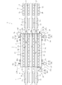
- FIG. 2 is a plan view of a plate glass manufacturing apparatus.
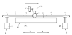
- FIG. 3 is a side view showing the end face processing apparatus.
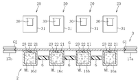
- 4 is a cross-sectional view taken along line IV-IV in FIG.
- FIG. 5 is a flowchart showing a method for manufacturing a plate glass.
- FIG. 6 is a flowchart showing an end face processing step of the plate glass.
- FIG. 7 is a side view of the manufacturing apparatus showing a part of the edge glass processing step.
- FIG. 8 is a side view of the manufacturing apparatus showing a part of the end face processing step of the plate glass.
- FIG. 9 is a side view of the manufacturing apparatus showing a part of the edge glass processing step.
- FIG. 1 is a side view of a plate glass manufacturing apparatus according to the present invention.
- FIG. 2 is a plan view of a plate glass manufacturing apparatus.
- FIG. 3 is a side view showing the end face
- FIG. 10 is a side view of the end face processing apparatus showing a part of the end face processing step of the plate glass.
- 11 is a cross-sectional view taken along line XI-XI in FIG.
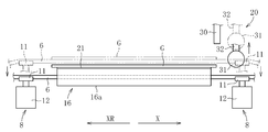
- FIG. 12 is a side view of the end face processing apparatus showing a part of the end face processing step of the plate glass.
- FIG. 13 is a side view of the end surface processing apparatus which shows a part of end surface processing process of plate glass.
- or FIG. 13 shows one Embodiment of the manufacturing method and manufacturing apparatus of the plate glass which concern on this invention.
- the manufacturing apparatus 1 includes a transport device 2 that transports the glass sheet G in a predetermined direction (transport direction X), an end surface processing device 3 that processes the end surface of the plate glass G, and end surface processing.
- a cutting device 4 disposed upstream of the device 3 and a cleaning device 5 disposed downstream of the end face processing device 3 are provided.
- the conveying device 2 transfers the glass sheet G from the cutting device 4 to the end surface processing device 3 and from the end surface processing device 3 to the cleaning device 5.
- the transport device 2 includes a first standby position WP1 and a processing position CP that performs processing by the end face processing device 3 on the downstream side of the first standby position WP1 in the process of transporting the plate glass G.
- the plate glass G is moved to the second standby position WP2 for waiting the plate glass G on the downstream side of the position CP.
- the conveyance apparatus 2 stops the plate glass G in each position WP1, CP, WP2 in conjunction with a sensor (not shown).
- the conveying device 2 includes a plurality of conveying belts 6 that convey the plate glass G, a driving device 7 for the conveying belt 6, an elevating device 8 that moves a part of the conveying belt 6 up and down, and a holding device that holds the plate glass G in a predetermined position.
- the conveyor belt 6 is configured endlessly by rubber or other elastic body, and is driven by the driving device 7 to move the plate glass G placed on the upper portion thereof.
- three conveyor belts 6 are illustrated, but the number of conveyor belts 6 is not limited to this, and can be set as appropriate according to the size of the glass sheet G.
- Each conveyor belt 6 is arranged at equal intervals.
- the driving device 7 has a plurality of pulleys 10 around which the conveyor belt 6 is wound, and a motor (not shown) that drives the pulleys 10.
- the driving device 7 is not limited to the pulley 10 described above, and can drive the conveyor belt 6 by a sprocket and other various driving bodies.
- the elevating device 8 includes a guide member 11 that guides the conveyor belt 6 and an actuator 12 that moves the guide member 11 up and down.
- the guide member 11 can be made of, for example, a synthetic resin. As shown in FIG. 2, the guide member 11 has a groove 11 a that guides the conveyance belt 6.
- the actuator 12 includes a cylinder device, but is not limited to this. The actuator 12 changes the position of the guide member 11 to a standby position and a position above the standby position.
- the holding device 9 is disposed so as to correspond to the second standby position WP2 of the plate glass G.
- the holding device 9 includes a plurality of holding members 13 that can hold the plate glass G, and an actuator 14 that raises and lowers each holding member 13.
- the holding member 13 is a hollow rod-shaped member made of metal and configured in a long shape.
- the width of the holding member 13 is set to be smaller than the interval between the transport belts 6. As a result, the holding member 13 can move in the vertical direction between the conveyor belts 6.
- the holding member 13 is filled with water or other liquids, but is not limited thereto, and may be filled with a gas-liquid mixed fluid formed by mixing a gas and a liquid.
- the holding member 13 has a hole 15 for discharging this liquid to the outside.
- the end face processing device 3 is arranged corresponding to the processing position CP of the plate glass G set by the transport device 2.
- the end face processing apparatus 3 is exemplified as a grinding apparatus that chamfers the end face of the plate glass G, but is not limited thereto, and may include a polishing apparatus that polishes the end face of the plate glass G.
- the end surface processing device 3 includes a surface plate 16 on which the plate glass G is placed, processing tools 17a and 17b, a positioning device 18 that positions the plate glass G, and displacement sensors 19a to 19c that measure the position of the end surface of the plate glass G. And a surface plate cleaning device 20 for cleaning the surface plate 16.
- the surface plate 16 is divided into a plurality of (four in the illustrated example) component members 16a to 16d. As shown in FIGS. 2 to 4, the constituent members 16a to 16d are formed in a long shape, and are arranged in parallel at a constant interval. As a result, a space (running path) through which the conveyor belt 6 can pass is formed between the constituent members 16a to 16d.
- Each of the constituent members 16a to 16d is a rod-like member configured in a hollow shape.
- Each of the constituent members 16a to 16d is filled with a gas-liquid mixed fluid ML obtained by mixing a gas (for example, air) and a liquid (for example, water).
- a support portion 21 that supports the lower surface of the glass sheet G is provided on the upper surface of each of the constituent members 16a to 16d.
- the support portion 21 is formed in an elongated shape and is formed of an elastic body such as rubber.
- the support portion 21 has a hole 22 for discharging the gas-liquid mixed fluid ML filled in the constituent members 16a to 16d.
- a through hole 23 is formed on the upper surface of each of the constituent members 16a to 16d so as to penetrate the constituent members 16a to 16d.
- a suction device and a pressure feeding device are connected to each of the structural members 16a to 16d. Due to the action of the suction device, each of the constituent members 16a to 16d adsorbs the plate glass G placed on the support portion 21 through the hole 22 and the through hole 23 of the support portion 21. That is, the hole 22 and the through hole 23 associated with each of the constituent members 16a to 16d function as a fixing portion that fixes the plate glass G to the support portion 21. Further, the hole 22 and the through hole 23 discharge the gas-liquid mixed fluid ML filled in the constituent members 16a to 16d to the support portion 21 side by the action of the pressure feeding device.
- the processing tools 17a and 17b are configured by a grinding tool (grinding stone) such as a diamond wheel.
- the processing tools 17 a and 17 b include a processing tool 17 a that processes the end face of one side G ⁇ b> 1 and a processing tool 17 a that processes the end faces of the two sides G ⁇ b> 1 and G ⁇ b> 2 of the plate glass G. And a processing tool 17b for processing the end face.
- Each processing tool 17a, 17b moves linearly from one end of each side G1, G2 to the other end while rotating (indicated by a solid line and a two-dot chain line), thereby each side G1, G1 of the glass sheet G.
- the end face in G2 is ground (chamfered) over its entire length.
- linear movement of each processing tool 17a, 17b is performed, for example with a linear motion guide, it is not limited to this.
- the positioning device 18 includes two pressing members 24a and 24b that can come into contact with the first side G1 of the rectangular plate glass G placed on the support portion 21 of the surface plate 16, and Two receiving members 25a and 25b that can abut on the second side G2 opposite to the first side G1, and a third that makes a right angle to the first side G1 and the second side G2.
- the sides G1 to G4 of the plate glass G are located outside the outer peripheral edge of the surface plate 16, and the pressing members 24a to 24c and the receiving members 25a to 25c are outside the surface plate 16. It is arranged outside the periphery, and further outside the four sides G1 to G4 of the plate glass G. Accordingly, the glass sheet G is supported at three points by a total of three receiving members 25a to 25c, and is also supported at three points by a total of three pressing members 24a to 24c.
- the pressing members 24a to 24c and the receiving members 25a to 25c are configured to come into contact with the glass sheet G when positioning the glass sheet G, and retract from the glass sheet G when positioning is completed.
- Each of the pressing members 24a to 24c includes a circular contact pressing body 26 that contacts each corresponding side G1 and G3 of the glass sheet G, and each side G1 and G3 of the plate glass G with respect to each contact pressing body 26. And an actuator 27 for applying a moving force in the orthogonal direction.
- the receiving members 25a to 25c have columnar (or cylindrical) contact receiving bodies 28 that contact the corresponding sides G2 and G4 of the plate glass G.
- the contact receiving body 28 is made of an elastic body and is supported by a biasing member 29 such as a spring or a fluid pressure cylinder. Therefore, each contact receiving body 28 is movable together with the plate glass G while maintaining the contact with the corresponding sides G2 and G4 of the plate glass G.
- the displacement sensors 19a to 19c include two displacement sensors 19a that can abut on the first side G1 of the glass sheet G and two that can abut on the second side G2 of the glass sheet G. Displacement sensor 19b, and one displacement sensor 19c that can come into contact with the third side G3.
- each of the displacement sensors 19a to 19c is a contact type sensor and has a contactor capable of contacting each corresponding side G1 to G3 of the glass sheet G.
- Each displacement sensor 19a to 19c can measure the amount of positional deviation of the plate glass G generated during positioning by comparing the position data measured in contact with the plate glass G and the reference value.
- the surface plate cleaning device 20 is disposed above the surface plate 16.
- the surface plate cleaning device 20 includes a plurality of shower nozzles 30 that discharge a cleaning liquid and a plurality of cleaning brushes 31 that can come into contact with the surface plate 16.
- the number of shower nozzles 30 is four, which is the same as the number of component members 16a to 16d, so that the cleaning liquid is individually discharged to the component members 16a to 16d of the surface plate 16.
- the number of cleaning brushes 31 is four, the same as the number of component members 16a to 16d.
- the shower nozzles 30 and the cleaning brushes 31 are arranged at a predetermined interval, like the constituent members 16a to 16d of the surface plate 16.
- the shower nozzle 30 is configured to reciprocate in the conveyance direction X of the glass sheet G and the opposite direction (hereinafter referred to as “anti-conveyance direction”) XR by a moving mechanism (not shown).
- Each shower nozzle 30 is disposed above the constituent members 16a to 16d of the surface plate 16 so as to face downward, and is configured to discharge a cleaning liquid composed of a liquid or a gas-liquid mixed fluid downward.
- the cleaning brush 31 is configured to reciprocate in the transport direction X and the counter-transport direction XR of the glass sheet G by a moving mechanism, like the shower nozzle 30.
- the cleaning brush 31 is moved at the same speed as the shower nozzle 30 is moved.
- the cleaning brush 31 is configured to move in the vertical direction by an actuator 32. That is, the cleaning brush 31 can be repositioned between a retracted position above the surface plate 16 and a cleaning position that is lowered from the retracted position and contacts the support portion 21 of the constituent members 16a to 16d of the surface plate 16. Is done.
- the cleaning brush 31 is driven to rotate by a motor (not shown).
- the cutting device 4 has a scribe wheel such as a diamond cutter.
- the cutting device 4 forms scribe lines on the glass substrate by the scribe wheel, and folds the glass substrate along the scribe lines to form a plate glass G having a predetermined size.
- the cleaning device 5 has a supply device for supplying a predetermined cleaning liquid to the plate glass G and a rotatable cleaning head.
- the cleaning device 5 brings the cleaning head into contact with the surface of the plate glass G while supplying the cleaning liquid to the plate glass G by the supply device, and removes foreign matters attached to the plate glass G by the rotation.
- the manufacturing method of the plate glass G includes a forming step S1, a cutting step S2, an end face processing step S3, and a cleaning step S4.
- this method includes a conveying step of moving the glass sheet G from the cutting device 4 to the end surface processing device 3 and from the end surface processing device 3 to the cleaning device 5.
- a known float method, roll-out method, slot down draw method, redraw method or the like can be used, but it is preferable to form the glass substrate by the overflow down draw method.
- the overflow down draw method molten glass is poured into an overflow groove provided on the upper part of a substantially wedge-shaped cross section, and the molten glass overflowing on both sides from the overflow groove is formed along the side wall portions on both sides of the molded body. While flowing down, they are fused and integrated at the lower end of the molded body, and a single glass substrate is continuously formed. Thereby, a large-sized glass substrate with high accuracy is formed.
- the glass substrate is cut by scribing with the cutting device 4 to obtain a plate glass G having a predetermined size.
- a scribe wheel is run along a planned cutting line set on the glass substrate, and a scribe line having a predetermined depth is engraved on the glass substrate along the planned cutting line. Thereafter, a bending moment is applied to the periphery of the scribe line, and the plate glass G is broken along the scribe line. A plurality of plate glasses G are obtained by this folding.
- the plate glass G obtained by cutting process S2 is conveyed from the cutting device 4 to the end surface processing apparatus 3 by a conveyance process. Specifically, the sheet glass G temporarily kept at the first standby position WP ⁇ b> 1 by the transport device 2 is carried into the processing position CP set with respect to the surface plate 16 of the end face processing device 3. When the processing by the end face processing device 3 is completed, the plate glass G is unloaded from the surface plate 16, moved to the second standby position WP2, and temporarily held.
- the end surface processing step S3 includes a positioning step S31 of the plate glass G by the positioning device 18, a fixing step S32 for fixing the plate glass G to the surface plate 16, and the end surfaces of the plate glass G by the displacement sensors 19a to 19c.
- a measuring step S33 for measuring the position of the plate glass a plate glass cleaning step S34 for cleaning the upper surface of the plate glass G fixed to the surface plate 16, and a grinding step S35 for chamfering the end surface of the plate glass G by the processing tools 17a and 17b.
- a platen washing step S36 for washing the support portion 21 of the platen 16.
- FIG. 7 shows a state immediately before starting the processing of the glass sheet G arranged at the processing position CP.
- the plate glass G that has already been processed is on standby. Further, a new plate glass G cut by the cutting device 4 is moving toward the transport device 2.
- the manufacturing apparatus 1 waits for the glass sheet G at the second standby position WP2 while receiving the new glass sheet G from the cutting device 4 by the transport device 2 and is at the processing position CP by the end face processing device 3.
- the plate glass G is processed.
- the transport device 2 starts the holding device 9.
- the holding member 13 of the holding device 9 is lifted by the operation of the actuator 14 and lifts the plate glass G supported by the transport belt 6.
- the plate glass G will be in the state spaced apart from the conveyance belt 6, ie, the state located above 2nd standby position WP2.
- the plate glass G arranged at the second standby position WP2 is used. It is held at a position above the second standby position WP2 by the holding device 9 (holding step). At this time, the holding member 13 discharges liquid from the hole 15. Thereby, this liquid intervenes between the holding member 13 and the plate glass G, and the generation of scratches on the plate glass G in the holding step is prevented.
- the conveying device 2 starts the conveying belt 6 and receives a new plate glass G from the cutting device 4.
- the transport device 2 stops the transport belt 6 after moving the plate glass G to the first standby position WP1. Note that the glass sheet G held above the second standby position WP2 does not move when the transport belt 6 is started.
- the end surface processing device 3 starts processing the end surface of the plate glass G at the processing position CP. Specifically, a positioning step S31, a fixing step S32, a measuring step S33, a plate glass cleaning step S34, a grinding step S35, and a surface plate cleaning step S36 are sequentially executed.
- the contact pressing bodies 26 of the two pressing members 24a and 24b push the first side G1 of the glass sheet G, and the contact pressing body 26 of one pressing member 24c is the third side. G3 is pushed.
- the second side G2 of the glass sheet G comes into contact with the contact receiving body 28 of the two receiving members 25a and 25b, and the fourth side G4 has the contact receiving body 28 of the single receiving member 25c. (See FIG. 2).
- the plate glass G is positioned with respect to the surface plate 16.
- the positioning device 18 is retracted from the glass sheet G, and the fixing step S32 is executed.
- the fixing step S ⁇ b> 32 a negative pressure is generated on the back side of the plate glass G through the holes 22 and 23 of the surface plate 16 by the suction device, and thereby the plate glass G is sucked and held on the support portion 21 of the surface plate 16.
- the measuring step S33 is executed.
- the displacement sensors 19a to 19c come into contact with the end faces of the corresponding sides G1 to G3 of the corresponding glass sheet G and measure their positions (displacements).
- a deviation amount from the reference position in the glass sheet G positioned in the positioning step S31 is detected.
- the plate glass cleaning step S34 is executed.
- the shower nozzle 30 stopped on the downstream side of the plate glass G is moved along the counter-transport direction XR, and the shower nozzle 30 is moved. Then, the cleaning liquid is discharged to the plate glass G located below.
- the shower nozzle 30 injects the cleaning liquid onto the glass sheet G before the grinding process S35 by the processing tools 17a and 17b is started.
- the cleaning liquid remains on the upper surface of the plate glass G, glass powder generated from the plate glass G in the subsequent grinding step S35 is prevented from adhering to the upper surface of the plate glass G.
- the cleaning brush 31 passes above the plate glass G along the counter-transport direction XR together with the shower nozzle 30 without rotating.
- the shower nozzle 30 stops the discharge of the cleaning liquid and is put together with the cleaning brush 31 on the spot. And wait.
- each processing tool 17a, 17b is determined based on the amount of shift of the end face of the plate glass G measured by each displacement sensor 19a-19c.
- Each processing tool 17a, 17b grinds the end face based on the determined grinding amount.
- Each processing tool 17a, 17b grinds the end face from one end of the first side G1 and the second side G2 to the other end.
- Each processing tool 17a, 17b moves along the counter-transport direction XR so as to follow the shower nozzle 30 while the shower nozzle 30 of the surface plate cleaning device 20 moves, and grinds the end surface of the plate glass G.
- the moving speed of each processing tool 17a, 17b is equal to or lower than the moving speed of the shower nozzle 30, and the processing tools 17a, 17b do not pass the shower nozzle 30.
- the tact time relating to the production of the plate glass G can be shortened.
- Each processing tool 17a, 17b returns to the standby position on the one end portion side of the plate glass G in preparation for the next grinding process after grinding the end surface from one end portion to the other end portion of the plate glass G.
- a new plate glass G has arrived at the first standby position WP1 by the transport process.
- the holding device 9 returns the held plate glass G to the transport belt 6. That is, the holding device 9 lowers the holding member 13 and returns it to the standby position (position indicated by a two-dot chain line in FIG. 9).
- the glass sheet G is separated from the holding member 13 and is again disposed at the second standby position WP2 on the transport belt 6.
- the sheet glass G is simultaneously conveyed by the conveying device 2.
- the end surface processing apparatus 3 operates the pressure feeding device to discharge the gas-liquid mixed fluid ML from the holes 22 and 23 of the constituent members 16a to 16d in the surface plate 16, thereby adsorbing and fixing the plate glass G. Is released.
- the guide member 11 in the lifting device 8 of the transport device 2 is raised.
- the conveyor belt 6 moves above the support portion 21 of the surface plate 16 and lifts the plate glass G.
- the plate glass G is separated from the support portion 21 of the surface plate 16 and is positioned above the processing position CP.
- the conveyance device 2 starts the conveyance belt 6 and simultaneously conveys the glass sheets G along the conveyance direction X to the downstream side. That is, the plate glass G that has been waiting at the second standby position WP2 is moved to the cleaning device 5, the plate glass G that has been processed at the processing position CP is moved to the second standby position WP2, and the first standby position is reached. The plate glass G waiting at WP1 is moved to the processing position CP.
- the surface plate cleaning step S36 is started while these plate glasses G are moving. As shown in FIGS. 10 and 11, the surface plate cleaning device 20 operates the actuator 32 to lower the cleaning brush 31. Each cleaning brush 31 comes into contact with the support portion 21 of the corresponding component 16a to 16d of the surface plate 16. Moreover, the cleaning brush 31 starts rotating by being driven by the motor.
- each cleaning brush 31 contacts only the support portion 21 of each component 16a to 16d (see FIG. 11).
- the glass sheet G at the processing position CP has started to move to the second standby position WP2, and the cleaning brush 31 and the shower nozzle 30 move along the transport direction X so as to follow the glass sheet G.
- the shower nozzle 30 and the cleaning brush 31 move to the downstream side at substantially the same speed as the conveying speed of the sheet glass G on the conveying belt 6 by the operation of the moving mechanism.
- the cleaning brush 31 cleans the support portion 21 of the surface plate 16 while rotating in a direction opposite to the moving direction. That is, as shown in FIG. 12, the cleaning brush 31 moving in the right direction (conveying direction X) toward the paper surface rotates counterclockwise (counterclockwise). By such rotation, the cleaning brush 31 can reliably separate foreign substances such as glass powder attached to the support portion 21 of the surface plate 16.
- this surface plate cleaning step S36 cleaning with the cleaning brush 31 is performed while discharging the gas-liquid mixed fluid ML to the support portion 21 from the holes 22 and 23 in the constituent members 16a to 16d of the surface plate 16.
- the washing brush 31 precedes and the shower nozzle 30 moves at the same speed so that it may follow.
- the cleaning brush 31 immediately after the foreign matter adhering to the support portion 21 of each of the constituent members 16a to 16d is separated by the cleaning brush 31, it can be reliably washed off with the cleaning liquid of the shower nozzle 30.
- the cleaning brush 31 finishes cleaning the support portions 21 of the constituent members 16a to 16d related to the surface plate 16
- the cleaning brush 31 is raised by the operation of the actuator 32 in the surface plate cleaning device 20, and the standby position ( Return to the position indicated by the two-dot chain line. Further, the shower nozzle 30 is stopped together with the cleaning brush 31, and the discharge of the cleaning liquid is also stopped. Thus, the surface plate cleaning step S36 is completed.
- the plate glass G that has been waiting at the first standby position WP1 arrives at the processing position CP.
- the plate glass G is disposed above the surface plate 16 while being supported by the conveyor belt 6.
- the lifting device 8 lowers the guide member 11 located at the upper position and returns it to the standby position.
- the plate glass G descend
- the conveyor belt 6 moves below the support portion 21 of the surface plate 16. As described above, the state returns to the state shown in FIG. 7, and the above operation is repeated thereafter.
- the plate glass G is rotated by 90 ° in the horizontal direction to change its posture, and the remaining two Although the end faces related to the sides G3 and G4 are ground, this process is not shown. Further, after the grinding process S35 is performed, a corner cutting process (not shown) of the plate glass G may be performed, but the present invention is not limited to this.
- a cleaning step S4 is performed.
- the plate glass G for which the end face processing has been finished is transferred to the cleaning device 5, and the cleaning liquid is supplied by the supply device, and the surface of the plate glass G is cleaned by the cleaning head.
- the plate glass G is commercialized through the above steps S1 to S4.
- the foreign matter adhering to the surface plate 16 can be removed by bringing the cleaning brush 31 into contact with the surface plate 16 in the surface plate cleaning step S36.
- the foreign matter can be washed away by separating and discharging the cleaning liquid from the shower nozzle 30 toward the surface plate 16. In this way, the foreign matter adhering to the surface plate 16 can be reliably removed by spraying the cleaning liquid from the cleaning brush 31 and the shower nozzle 30.
- the processing is performed until the plate glass G that has been subjected to the end face processing is unloaded from the surface plate 16 and a new plate glass G for processing is fixed to the surface plate 16.
- the tact time relating to the production of the plate glass G is not prolonged. Therefore, it is possible to manufacture the plate glass G efficiently.
- the cleaning with the cleaning brush 31 is completed, the cleaning brush 31 is retracted upward from the surface plate 16, and therefore the cleaning brush 31 does not interfere with the conveyance of the plate glass G.
- this invention is not limited to the structure of the said embodiment, It is not limited to the above-mentioned effect.
- the present invention can be variously modified without departing from the gist of the present invention.
- the present invention is not limited thereto.
- the surface plate 16 may be cleaned by the surface plate cleaning device 20 having only the shower nozzle 30, or the surface plate 16 may be cleaned by the surface plate cleaning device 20 having only the cleaning brush 31.
- the example in which the surface plate 16 is cleaned by rotating the cleaning brush 31 has been described.
- the present invention is not limited to this, and the surface plate 16 is vibrated without rotating the cleaning brush 31. You may make it wash
Landscapes
- Engineering & Computer Science (AREA)
- Mechanical Engineering (AREA)
- Chemical & Material Sciences (AREA)
- Ceramic Engineering (AREA)
- Inorganic Chemistry (AREA)
- Grinding And Polishing Of Tertiary Curved Surfaces And Surfaces With Complex Shapes (AREA)
- Re-Forming, After-Treatment, Cutting And Transporting Of Glass Products (AREA)
- Grinding-Machine Dressing And Accessory Apparatuses (AREA)
Abstract
本方法は、板ガラスGを固定する定盤16と、加工具17a,17bとを備える端面加工装置3により、板ガラスGの端面に加工を施す端面加工工程S3と、所定の搬送方向に沿って、板ガラスGを搬送装置2によって定盤16に対して搬入し又は搬出する搬送工程とを備える。端面加工工程S3は、定盤16の上方位置に配置される定盤洗浄装置10によって定盤16を洗浄する定盤洗浄工程S36を備える。定盤洗浄工程S36は、定盤16に固定された板ガラスGに対して加工具17a,17bによる端面加工が終了した後に、この板ガラスGを搬出し、新たな加工用の板ガラスGを定盤16に固定するまでの間に、定盤洗浄装置20により定盤16を洗浄する。
Description
本発明は、その端面に加工が施されてなる板ガラスを製造する方法に関する。
液晶ディスプレイ(LCD)、プラズマディスプレイ(PDP)、有機ELディスプレイ(OLED)などのフラットパネルディスプレイ(FPD)用の板ガラスを製造する場合、例えばダウンドロー法等の成形法により成形された大型のガラス基板を切断することで、所定の大きさの板ガラスを形成する。具体的には、例えばダイヤモンドカッター等のスクライブホイールを使用してガラス基板を割断することにより、板ガラスが形成される。
ガラス基板を割断して板ガラスを形成すると、その切断面(端面)には、数μm~100μm程度の深さの微小なクラックが形成される。このクラックは、板ガラスの機械的強度の低下を招くことから、板ガラスの端面を加工することによって除去される。すなわち、板ガラスの機械的強度を高め、板ガラスの割れや欠けを防止し、後工程でのハンドリングを行い易くするために、板ガラスの端面には、研削加工(面取り)及び研磨加工が施される。
板ガラスの製造装置としては、特許文献1に開示されるように、帯状に成形されたガラスリボンに切線(スクライブ線)を入れる切機と、この切線に沿ってガラスリボンの折割を行う折機と、折割後に形成される板ガラスの端面の研削を行う面取装置とを備えたものがある。
この製造装置における面取装置は、板ガラスを吸引可能な定盤(テーブル)と、板ガラスの端面の位置を測定するレーザ変位計と、面取用砥石とを備える。面取装置は、レーザ変位計(非接触センサ)によって、定盤に吸着固定された板ガラスの端面の位置情報を取得するとともに、この位置情報に基づいて面取用砥石の位置制御を実行する。これにより、面取装置は、板ガラスの位置決めを行うことなく面取加工を行うことができる。
従来の製造装置における面取装置は、定盤に板ガラスを吸着固定させた状態で面取用砥石により端面の加工を行うが、この面取加工によって生じたガラス粉等の異物が定盤に残る場合がある。このような場合、面取加工を施すべく新たな板ガラスを定盤に固定すると、この異物が板ガラスに付着し、板ガラスを損傷させ、製品としての品位を低下させてしまうおそれがある。
本発明は上記の事情に鑑みてなされたものであり、異物が残らないように定盤を洗浄するとともに板ガラスを効率良く製造することを技術的課題とする。
本発明は上記の課題を解決するためのものであり、板ガラスを固定する定盤と、加工具とを備える端面加工装置により、前記板ガラスの端面に加工を施す端面加工工程と、所定の搬送方向に沿って、前記板ガラスを搬送装置によって定盤に対して搬入し又は搬出する搬送工程とを備える板ガラスの製造方法であって、前記端面加工工程は、前記定盤の上方位置に配置される定盤洗浄装置によって前記定盤を洗浄する定盤洗浄工程を備え、前記定盤洗浄工程は、前記定盤に固定された前記板ガラスに対して前記加工具による端面加工が終了した後に、前記搬送装置により前記板ガラスを前記定盤から搬出し、新たな加工用の板ガラスを前記定盤に搬入して固定するまでの間に、前記定盤洗浄装置により前記定盤を洗浄することを特徴とする。
上記のように、定盤洗浄工程は、加工が終了した板ガラスを定盤から搬出し、新たな加工用の板ガラスを定盤に固定するまでの間に、定盤洗浄装置によって行われる。これにより、端面加工工程を阻害することなく定盤の洗浄を行うことができるため、板ガラスの製造に係るタクトタイムを長期化させることがない。したがって、板ガラスを効率良く製造することが可能である。
本発明に係る板ガラスの製造方法では、前記定盤洗浄装置は、前記定盤に向かって洗浄液を吐出するノズルと、前記定盤に接触可能な洗浄ブラシとを備え、前記定盤洗浄工程は、前記洗浄ブラシを前記定盤に接触させて回転させながら移動させるとともに、前記ノズルによって前記洗浄液を前記定盤に吐出させながら前記洗浄ブラシと共に移動させることで前記定盤を洗浄し、かつ洗浄後に前記洗浄ブラシを前記定盤から退避させることが望ましい。
これによれば、定盤洗浄工程において、洗浄ブラシを定盤に接触させ、回転させながら移動させることで、この定盤に付着する異物を分離させ、ノズルから洗浄液を定盤に向けて吐出することにより、この異物を確実に洗い流すことができる。また、定盤洗浄工程では、洗浄ブラシは、洗浄が終了した後に定盤から退避することから、新たな板ガラスを定盤に搬入する際に、洗浄ブラシが邪魔になることはない。
本発明に係る板ガラスの製造方法では、前記ノズルは、前記板ガラスを前記加工具によって加工する前に、前記板ガラスの上面に洗浄液を吐出することが望ましい。これにより、既に板ガラスに付着している異物を洗い流すことができるとともに、加工具による加工によって発生するガラス粉が板ガラスの上面に付着することを防止できる。
本発明に係る板ガラスの製造方法では、前記加工具は、前記板ガラスの前記搬送方向とは逆の方向に沿って移動しつつ前記板ガラスの端面を加工するように構成され得る。これにより、板ガラスの端面を効率良く加工できる。
本発明に係る板ガラスの製造方法では、前記洗浄ブラシは、前記板ガラスの前記搬送方向と同一の方向に移動するとともに、前記搬送方向とは逆の方向に回転することが望ましい。これにより、定盤の洗浄を効率良く行うことができる。
本発明に係る板ガラスの製造方法では、前記定盤は、複数の構成部材により構成されてなり、前記搬送装置は、前記複数の構成部材の間に配置される搬送ベルトを備え、前記洗浄ブラシは、前記搬送ベルトに接触することなく前記構成部材のみに接触するように構成され得る。このように洗浄ブラシを定盤のみに接触させることで、搬送工程を阻害することなく、迅速かつ確実に定盤を洗浄できる。
本発明によれば、異物が残らないように定盤を洗浄するとともに板ガラスを効率良く製造することが可能になる。
以下、本発明を実施するための形態について図面を参照しながら説明する。図1乃至図13は、本発明に係る板ガラスの製造方法及び製造装置の一実施形態を示す。
図1及び図2に示すように、製造装置1は、板ガラスGを所定の方向(搬送方向X)に搬送する搬送装置2と、板ガラスGの端面に加工を施す端面加工装置3と、端面加工装置3の上流に配置される切断装置4と、端面加工装置3の下流側に配置される洗浄装置5とを備える。
搬送装置2は、切断装置4から端面加工装置3へ、そして端面加工装置3から洗浄装置5へと板ガラスGを移送する。図1に示すように、搬送装置2は、板ガラスGの搬送過程において、第1待機位置WP1と、第1待機位置WP1の下流側にて端面加工装置3による加工を行う加工位置CPと、加工位置CPの下流側にて板ガラスGを待機させる第2待機位置WP2とに板ガラスGを移動させる。また、搬送装置2は、図示しないセンサと連動して、板ガラスGを各位置WP1,CP,WP2に停止させる。
搬送装置2は、板ガラスGを搬送する複数の搬送ベルト6と、搬送ベルト6の駆動装置7と、搬送ベルト6の一部を上下動させる昇降装置8と、板ガラスGを所定位置で保持する保持装置9とを備える。
搬送ベルト6は、ゴムその他の弾性体により無端状に構成されるとともに、駆動装置7に駆動されることで、その上部に載せられる板ガラスGを移動させる。なお、本実施形態では、三本の搬送ベルト6を例示するが、搬送ベルト6の数はこれに限定されず、板ガラスGのサイズに応じて適宜設定され得る。各搬送ベルト6は等間隔で配置されている。
駆動装置7は、搬送ベルト6が巻回される複数のプーリー10と、プーリー10を駆動するモータ(図示せず)とを有する。駆動装置7は、上記のプーリー10に限らず、スプロケットその他の各種駆動体により搬送ベルト6を駆動し得る。
昇降装置8は、搬送ベルト6を案内するガイド部材11と、このガイド部材11を上下動させるアクチュエータ12とを備える。ガイド部材11は、例えば合成樹脂により構成され得る。図2に示すように、ガイド部材11は、搬送ベルト6を案内する溝部11aを有する。アクチュエータ12は、シリンダ装置により構成されるが、これに限定されるものではない。アクチュエータ12は、ガイド部材11の位置を、待機位置と、この待機位置よりも上方の位置とに変更する。
図1に示すように、保持装置9は、板ガラスGの第2待機位置WP2に対応するように配置されている。保持装置9は、板ガラスGを保持可能な複数の保持部材13と、各保持部材13を昇降させるアクチュエータ14とを備える。
保持部材13は、金属製で長尺状に構成される中空状の棒状部材である。保持部材13の幅は、各搬送ベルト6の間隔よりも小さく設定されている。これにより、保持部材13は、搬送ベルト6の間で上下方向に移動できる。保持部材13の内部には、水その他の液体が充填されるが、これに限らず、気体と液体とを混合してなる気液混合流体を充填してもよい。保持部材13は、この液体を外部に吐出する孔15を有する。
端面加工装置3は、搬送装置2により設定される板ガラスGの加工位置CPに対応して配置されている。本実施形態において、端面加工装置3は、板ガラスGの端面に対して面取りを施す研削装置として例示されるが、これに限定されず、板ガラスGの端面に研磨を施す研磨装置を含み得る。
端面加工装置3は、板ガラスGが載置される定盤16と、加工具17a,17bと、板ガラスGの位置決めを行う位置決め装置18と、板ガラスGの端面の位置を測定する変位センサ19a~19cと、定盤16の洗浄を行う定盤洗浄装置20と、を備える。
定盤16は、複数(図例では四本)の構成部材16a~16dに分割されてなる。図2乃至図4に示すように、各構成部材16a~16dは、長尺状に構成されるとともに、一定の間隔をおいて並設されている。これにより、各構成部材16a~16dの間には、搬送ベルト6が通過可能な空間(走行路)が形成されている。
各構成部材16a~16dは、中空状に構成された棒状部材である。各構成部材16a~16dの内部には、気体(例えば空気)と液体(例えば水)とを混合させてなる気液混合流体MLが充填されている。また、各構成部材16a~16dの上面には、板ガラスGの下面を支持する支持部21が設けられている。支持部21は、長尺状に構成されるとともに、例えばゴム等の弾性体により構成される。支持部21は、各構成部材16a~16dに充填されている気液混合流体MLを吐出する孔22を有する。また、各構成部材16a~16dの上面には、この構成部材16a~16dを内外貫通する貫通孔23が形成されている。
各構成部材16a~16dには、図示しない吸引装置及び圧送装置が接続されている。吸引装置の作用により、各構成部材16a~16dは、支持部21の孔22及び貫通孔23を介して、支持部21に載置された板ガラスGを吸着する。すなわち、各構成部材16a~16dに係る孔22及び貫通孔23は、板ガラスGを支持部21に固定する固定部として機能する。また、圧送装置の作用により、孔22及び貫通孔23は、構成部材16a~16dの内部に充填されている気液混合流体MLを支持部21側に吐出する。
加工具17a,17bは、ダイヤモンドホイール等の研削具(砥石)により構成される。図2に示すように、加工具17a,17bは、板ガラスGの二辺G1,G2に係る端面を加工するように、一方の辺G1の端面を加工する加工具17aと、他方の辺G2の端面を加工する加工具17bとを有する。各加工具17a,17bは、回転しながら各辺G1,G2の一端部から他端部に向かって直線的に移動する(実線及び二点鎖線で示す)ことで、板ガラスGの各辺G1,G2における端面をその全長にわたって研削(面取り)する。なお、各加工具17a,17bの直線移動は、例えばリニアモーションガイドにより行われるが、これに限定されるものではない。
図2に示すように、位置決め装置18は、定盤16の支持部21上に載せられた四角形状の板ガラスGの第1の辺G1に当接可能な二個の押付部材24a,24bと、この第1の辺G1と対向する第2の辺G2に当接可能な二個の受止部材25a,25bと、これら第1の辺G1及び第2の辺G2に対して直角を為す第3の辺G3に当接可能な一個の押付部材24cと、この第3の辺G3と対向する第4の辺G4に当接可能な一個の受止部材25cとを有する。
この場合、板ガラスGの各辺G1~G4は、定盤16の外周縁よりも外側に位置しており、また各押付部材24a~24c及び各受止部材25a~25cは、定盤16の外周縁よりも外側、更には板ガラスGの四辺G1~G4よりも外側に配置されている。したがって、この板ガラスGは、計三個の受止部材25a~25cによって三点で支持されると共に、計三個の押付部材24a~24cによっても三点で支持される。
押付部材24a~24c及び受止部材25a~25cは、板ガラスGの位置決めを行う際に、板ガラスGに接触し、そして位置決めが終了すると、板ガラスGから退避するように構成される。
各押付部材24a~24cは、板ガラスGの対応する各辺G1、G3にそれぞれ当接する円形状の当接押し体26と、各当接押し体26に対して板ガラスGの各辺G1、G3と直交する方向への移動力をそれぞれ付与するアクチュエータ27とを有する。
受止部材25a~25cは、板ガラスGの対応する各辺G2,G4に当接する円柱状(または円筒状)の当接受け体28を有する。当接受け体28は、弾性体により構成されるとともに、バネ或いは流体圧シリンダ等の付勢部材29によって支持されている。したがって、各当接受け体28は、板ガラスGの対応する各辺G2,G4との当接をそれぞれ維持した状態で板ガラスGと共に移動可能とされている。
図2に示すように、変位センサ19a~19cは、板ガラスGの第1の辺G1に当接可能な二個の変位センサ19aと、板ガラスGの第2の辺G2に当接可能な二個の変位センサ19bと、第3の辺G3に当接可能な一個の変位センサ19cとを含む。
また、図2に示すように、各変位センサ19a~19cは、接触式センサであって、板ガラスGの対応する各辺G1~G3に当接可能な接触子をそれぞれ有する。各変位センサ19a~19cは板ガラスGに接触して測定した位置データと、基準値とを比較することで、位置決めの際に生じた板ガラスGの位置ずれの量を計測できる。
図1に示すように、定盤洗浄装置20は、定盤16の上方位置に配置されている。この定盤洗浄装置20は、洗浄液を吐出する複数のシャワーノズル30と、定盤16に接触可能な複数の洗浄ブラシ31とを備える。シャワーノズル30の数は、定盤16の各構成部材16a~16dに対し個別に洗浄液を吐出するように、構成部材16a~16dの数と同じ四個になっている。同様に洗浄ブラシ31の数は、構成部材16a~16dの数と同じ四個である。各シャワーノズル30及び各洗浄ブラシ31は、定盤16の構成部材16a~16dと同様に、所定の間隔で離間されて配置されている。
シャワーノズル30は、図示しない移動機構により、板ガラスGの搬送方向Xとその逆方向(以下「反搬送方向」という)XRとに往復移動するように構成される。各シャワーノズル30は、定盤16の構成部材16a~16dの上方で、下方を向くように配置され、液体又は気液混合流体からなる洗浄液を下方に吐出するように構成される。
洗浄ブラシ31は、シャワーノズル30と同様に、移動機構により、板ガラスGの搬送方向Xと反搬送方向XRとに往復移動するように構成される。洗浄ブラシ31の移動は、シャワーノズル30の移動と同じ速度で行われる。また、洗浄ブラシ31は、アクチュエータ32により、上下方向に移動するように構成される。すなわち、洗浄ブラシ31は、定盤16よりも上方の退避位置と、退避位置から下降して定盤16の構成部材16a~16dに係る支持部21に接触する洗浄位置とに位置変更可能に構成される。また、洗浄ブラシ31は、図示しないモータにより回転駆動される。
切断装置4は、ダイヤモンドカッター等のスクライブホイールを有する。切断装置4は、このスクライブホイールによって、ガラス基板にスクライブ線を刻設し、このスクライブ線を沿ってガラス基板を折り割ることで、所定寸法の板ガラスGを形成する。
洗浄装置5は、所定の洗浄液を板ガラスGに供給する供給装置と、回転可能な洗浄ヘッドとを有する。洗浄装置5は、供給装置により板ガラスGに洗浄液を供給しながら、洗浄ヘッドを板ガラスGの表面に接触させ、その回転により板ガラスGに付着する異物を除去する。
以下、上記の製造装置1を使用して板ガラスGを製造する方法について説明する。本実施形態に係る板ガラスGの製造方法は、図5に示すように、成形工程S1と、切断工程S2と、端面加工工程S3と、洗浄工程S4とを備える。その他、本方法は、板ガラスGを切断装置4から端面加工装置3へ、そして端面加工装置3から洗浄装置5へと移動させる搬送工程を備える。
成形工程S1では、公知のフロート法、ロールアウト法、スロットダウンドロー法、リドロー法等を使用することができるが、オーバーフローダウンドロー法によりガラス基板を成形することが好ましい。オーバーフローダウンドロー法は、断面が略くさび形の成形体の上部に設けられたオーバーフロー溝に溶融ガラスを流し込み、このオーバーフロー溝から両側に溢れ出た溶融ガラスを成形体の両側の側壁部に沿って流下させながら、成形体の下端部で融合一体化し、一枚のガラス基板を連続成形するというものである。これにより、精度の高い大型のガラス基板が成形される。
切断工程S2では、切断装置4によるスクライブ切断により、このガラス基板を切断し、所定寸法の板ガラスGを得る。この切断工程S2では、ガラス基板に設定される切断予定線に沿ってスクライブホイールを走行させ、ガラス基板に、切断予定線に沿って所定深さを有するスクライブ線を刻設する。その後、このスクライブ線の周辺に曲げモーメントを作用させ、板ガラスGをこのスクライブ線に沿って折り割る。この折割によって複数の板ガラスGを得る。
切断工程S2により得られた板ガラスGは、搬送工程により、切断装置4から端面加工装置3へと搬送される。具体的には、搬送装置2により、第1待機位置WP1にて一時的に待機させた板ガラスGを、端面加工装置3の定盤16に対して設定される加工位置CPへと搬入する。端面加工装置3による加工が終了すると、定盤16から板ガラスGを搬出し、第2待機位置WP2へと移動させ、一時待機させる。
端面加工工程S3は、図6に示すように、位置決め装置18による板ガラスGの位置決め工程S31と、板ガラスGを定盤16に固定する固定工程S32と、各変位センサ19a~19cによって板ガラスGの端面の位置を測定する測定工程S33と、定盤16に固定された板ガラスGの上面を洗浄する板ガラス洗浄工程S34と、加工具17a,17bによって板ガラスGの端面に対して面取りを行う研削加工工程S35と、定盤16の支持部21を洗浄する定盤洗浄工程S36とを備える。
以下、端面加工工程S3について、搬送工程との関係を交えつつ、図7乃至図13を参照しながら詳細に説明する。図7は、加工位置CPに配置された板ガラスGの加工を開始する直前の状態を示す。図7に示すように、第2待機位置WP2では、既に加工が終了した板ガラスGが待機中である。また、切断装置4により切断加工された新たな板ガラスGが搬送装置2に向かって移動中である。
この状態において、製造装置1は、第2待機位置WP2にある板ガラスGを待機させつつ、切断装置4から新たな板ガラスGを搬送装置2により受け取るとともに、端面加工装置3により、加工位置CPにある板ガラスGの加工を行う。
この際、図8に示すように、搬送装置2は、保持装置9を始動させる。保持装置9の保持部材13は、アクチュエータ14の動作により上昇し、搬送ベルト6に支持されている板ガラスGを持ち上げる。これにより、板ガラスGは、搬送ベルト6から上方に離間した状態、すなわち、第2待機位置WP2の上方に位置した状態となる。
このように、搬送工程では、加工位置CPに板ガラスGが配置された状態で、他の板ガラスGを第1待機位置WP1に配置するときに、第2待機位置WP2に配置されている板ガラスGを保持装置9により第2待機位置WP2の上方位置で保持する(保持工程)。このとき、保持部材13は、その孔15から液体を吐出している。これにより、保持部材13と板ガラスGとの間にこの液体が介在することになり、保持工程における板ガラスGに対する擦傷の発生が防止される。
次に、搬送装置2は、搬送ベルト6を始動させ、切断装置4から新たな板ガラスGを受け取る。図9に示すように、搬送装置2は、この板ガラスGを第1待機位置WP1に移動させた後、搬送ベルト6を停止させる。なお、第2待機位置WP2の上方にて保持される板ガラスGは、搬送ベルト6の始動によって移動することはない。
上記のように搬送装置2が動作する間に、端面加工装置3は、加工位置CPにある板ガラスGの端面の加工を開始する。具体的には、位置決め工程S31、固定工程S32、測定工程S33、板ガラス洗浄工程S34、研削加工工程S35、及び定盤洗浄工程S36が順に実行される。
位置決め工程S31では、二個の押付部材24a,24bの当接押し体26が板ガラスGの第1の辺G1を押動させると共に、一個の押付部材24cの当接押し体26が第3の辺G3を押動させる。この結果、板ガラスGの第2の辺G2が二個の受止部材25a,25bの当接受け体28に当接すると共に、第4の辺G4が一個の受止部材25cの当接受け体28に当接する(図2参照)。これにより、板ガラスGは、定盤16に対して位置決めされる。
位置決め工程S31が終了すると、位置決め装置18が板ガラスGから退避し、固定工程S32が実行される。固定工程S32では、吸引装置により、定盤16の各孔22,23を通じて板ガラスGの裏面側に負圧を生じさせ、これにより板ガラスGを定盤16の支持部21上に吸着保持させる。
固定工程S32が終了すると、測定工程S33が実行される。この測定工程S33では、各変位センサ19a~19cが、対応する板ガラスGの各辺G1~G3の端面に接触し、その位置(変位)を測定する。この測定工程S33により、位置決め工程S31において位置決めされた板ガラスGにおける基準位置からのずれ量が検出される。
この測定工程S33が終了すると、変位センサ19a~19cが板ガラスGから退避し、板ガラス洗浄工程S34が実行される。この板ガラス洗浄工程S34では、図3、図7乃至図9に示すように、板ガラスGの下流側にて停止しているシャワーノズル30を反搬送方向XRに沿って移動させつつ、このシャワーノズル30から洗浄液を下方に位置する板ガラスGへと吐出させる。このシャワーノズル30は、加工具17a,17bによる研削加工工程S35が開始される前に洗浄液を板ガラスGへと噴射する。
これにより、切断工程S2において板ガラスGの上面に付着した異物を除去することができる。さらに、板ガラスGの上面に洗浄液が残ることで、後に行われる研削加工工程S35において板ガラスGから発生するガラス粉が板ガラスGの上面に付着することを防止する。なお、洗浄ブラシ31は、回転することなく、シャワーノズル30と共に反搬送方向XRに沿って板ガラスGの上方を通過する。
図9に示すように、板ガラスGの下流側の端部から上流側の端部までの範囲で洗浄液を板ガラスGに噴射すると、シャワーノズル30は洗浄液の吐出を止め、洗浄ブラシ31とともにその場にて待機する。
研削加工工程S35では、各変位センサ19a~19cによって測定された板ガラスGにおける端面のずれ量に基づいて各加工具17a,17bの研削量が決定される。各加工具17a,17bは、決定された研削量に基づいて端面に対する研削を行う。各加工具17a,17bは、第1の辺G1及び第2の辺G2の一端部から他端部にわたって、その端面を研削する。
各加工具17a,17bは、定盤洗浄装置20のシャワーノズル30が移動する間に、このシャワーノズル30を追いかけるように反搬送方向XRに沿って移動し、板ガラスGの端面を研削する。この場合、各加工具17a,17bの移動速度は、シャワーノズル30の移動速度以下であり、加工具17a,17bがシャワーノズル30を追い越すことはない。このようにシャワーノズル30の移動中に研削加工工程S35を開始することにより、板ガラスGの製造に係るタクトタイムを短縮できる。
各加工具17a,17bは、板ガラスGの一端部から他端部まで、端面の研削加工を行った後、次回の研削加工に備えて、板ガラスGの一端部側における待機位置へと戻る。加工終了時には、搬送工程により新たな板ガラスGが第1待機位置WP1に到着している。この板ガラスGが到着すると、保持装置9は、保持していた板ガラスGを搬送ベルト6に戻す。すなわち、保持装置9は、保持部材13を下降させて待機位置(図9において二点鎖線で示す位置)へと戻す。これにより、板ガラスGは、保持部材13から離れ、再び搬送ベルト6における第2待機位置WP2に配置される。
研削加工工程S35が終了すると、搬送装置2による各板ガラスGの同時搬送が実行される。板ガラスGの搬送にあたり、端面加工装置3は、圧送装置を作動させて、定盤16における各構成部材16a~16dの各孔22,23から気液混合流体MLを吐出し、板ガラスGの吸着固定を解除する。
その後、図10に示すように、搬送装置2の昇降装置8におけるガイド部材11が上昇する。これにより、搬送ベルト6は、定盤16の支持部21よりも上方に移動し、板ガラスGを持ち上げる。これにより、板ガラスGは、定盤16の支持部21から離れ、加工位置CPの上方に位置することになる。
この状態で、搬送装置2は、搬送ベルト6を始動させ、各板ガラスGを同時に搬送方向Xに沿って下流側へと搬送する。すなわち、第2待機位置WP2にて待機していた板ガラスGを洗浄装置5へと移動させ、加工位置CPにて加工が終了した板ガラスGを第2待機位置WP2へと移動させ、第1待機位置WP1にて待機していた板ガラスGを加工位置CPへと移動させる。
定盤洗浄工程S36は、これらの板ガラスGの移動中に開始される。図10、図11に示すように、定盤洗浄装置20は、アクチュエータ32を作動させ、洗浄ブラシ31を下降させる。各洗浄ブラシ31は、対応する定盤16の構成部材16a~16dの支持部21に接触する。また、モータに駆動されることで、洗浄ブラシ31は回転を開始する。
この場合において、洗浄ブラシ31と搬送ベルト6とは側面視において重なる(図10参照)が、各洗浄ブラシ31は搬送ベルト6に接触しないように、間隔をおいて配置されている。このため、各洗浄ブラシ31は、各構成部材16a~16dの支持部21のみに接触する(図11参照)。
このとき、加工位置CPにあった板ガラスGが第2待機位置WP2への移動を開始しており、洗浄ブラシ31及びシャワーノズル30は、この板ガラスGを追いかけるように、搬送方向Xに沿って移動を開始する。シャワーノズル30及び洗浄ブラシ31は、移動機構の動作により、この搬送ベルト6における板ガラスGの搬送速度とほぼ同じ速度で、下流側へと移動する。このように、板ガラスGを搬送しながら、定盤16の洗浄を行うことにより、板ガラスGの製造に係るタクトタイムを可及的に短縮できる。
洗浄ブラシ31は、その移動方向に対して逆の方向に回転しながら、定盤16の支持部21を洗浄する。すなわち、図12に示すように、紙面に向かって右方向(搬送方向X)に移動する洗浄ブラシ31は、左回り(反時計回り)に回転する。このような回転により、洗浄ブラシ31は、定盤16の支持部21に付着したガラス粉等の異物を確実に分離させることができる。
この定盤洗浄工程S36では、定盤16の構成部材16a~16dにおける各孔22,23から気液混合流体MLを支持部21に吐出しながら、洗浄ブラシ31による洗浄を行う。このようにすることで、定盤16の支持部21に付着している異物を分離させ易くなる。また、定盤洗浄工程S36では、洗浄ブラシ31が先行し、シャワーノズル30がその後を追うように同じ速度で移動する。これにより、各構成部材16a~16dの支持部21に付着していた異物を、洗浄ブラシ31によって分離させた直後に、シャワーノズル30の洗浄液により確実に洗い落すことができる。
図13に示すように、洗浄ブラシ31は、定盤16に係る各構成部材16a~16dの支持部21を洗浄し終えると、定盤洗浄装置20におけるアクチュエータ32の動作によって上昇し、待機位置(二点鎖線で示す位置)へと戻る。また、シャワーノズル30は洗浄ブラシ31とともに停止し、洗浄液の吐出も停止させる。以上により、定盤洗浄工程S36が終了する。
なお、定盤洗浄工程S36の終了時には、第1待機位置WP1にて待機していた板ガラスGが加工位置CPへと到着する。図13において二点鎖線で示すように、板ガラスGは、搬送ベルト6によって支持された状態で、定盤16の上方位置に配置される。その後、昇降装置8は、上方位置にあるガイド部材11を下降させ、待機位置へと戻す。これにより、板ガラスGは、定盤16の上方位置からこの定盤16に向かって下降し、その支持部21(加工位置CP)に載置される。ガイド部材11が待機位置に戻ることにより、搬送ベルト6は、定盤16の支持部21よりも下方に移動する。以上により、図7に示す状態に戻り、以後、上記の動作が繰り返される。
なお、端面加工工程S3では、四角形状の板ガラスGの二辺G1,G2に係る端面の研削を行った後、この板ガラスGを水平方向において90°回転させてその姿勢を変更し、残りの二辺G3,G4に係る端面の研削が行われるが、この工程については図示していない。また、研削加工工程S35が行われた後に、板ガラスGのコーナーカット工程(図示せず)が実行され得るが、これに限定されるものではない。
端面加工工程S3が終了すると、洗浄工程S4が実行される。洗浄工程S4では、端面加工が終了した板ガラスGが洗浄装置5に移送され、供給装置によって洗浄液を供給するとともに、洗浄ヘッドによって板ガラスGの表面が洗浄される。以上の各工程S1~S4を経ることで、板ガラスGは製品化される。
以上説明した本実施形態に係る板ガラスGの製造方法及び製造装置1によれば、定盤洗浄工程S36において、洗浄ブラシ31を定盤16に接触させることで、この定盤16に付着する異物を分離させ、シャワーノズル30から洗浄液を定盤16に向けて吐出することにより、この異物を洗い流すことができる。このように洗浄ブラシ31とシャワーノズル30からの洗浄液の噴射により、定盤16に付着した異物を確実に除去することができる。
また、定盤洗浄工程S36では、端面加工が終了した板ガラスGを定盤16から搬出し、新たな加工用の板ガラスGを定盤16に固定するまでの間に行われる。これにより、端面加工工程S3を阻害することなく定盤16の洗浄を行うことができるため、板ガラスGの製造に係るタクトタイムを長期化させることがない。したがって、板ガラスGを効率良く製造することが可能である。また、洗浄ブラシ31による洗浄が終了すると、洗浄ブラシ31は定盤16から上方に退避することから、板ガラスGの搬送を洗浄ブラシ31が邪魔することはない
なお、本発明は、上記実施形態の構成に限定されるものではなく、上記した作用効果に限定されるものでもない。本発明は、本発明の要旨を逸脱しない範囲で種々の変更が可能 である。
上記の実施形態では、シャワーノズル30と洗浄ブラシ31とを備える定盤洗浄装置20により定盤16を洗浄する例を示したが、これに限定されない。シャワーノズル30のみを有する定盤洗浄装置20によって定盤16を洗浄してもよく、洗浄ブラシ31のみを有する定盤洗浄装置20により定盤16を洗浄してもよい。また、上記の実施形態では、洗浄ブラシ31を回転させることで定盤16を洗浄する例を示したが、これに限らず、洗浄ブラシ31を回転させることなく、振動させることで定盤16を洗浄するようにしてもよい。
2 搬送装置
3 端面加工装置
6 搬送ベルト
16 定盤
16a 定盤の構成部材
16b 定盤の構成部材
16c 定盤の構成部材
16d 定盤の構成部材
17a 加工具
17b 加工具
20 定盤洗浄装置
30 シャワーノズル
31 洗浄ブラシ
G 板ガラス
S3 端面加工工程
S36 定盤洗浄工程
3 端面加工装置
6 搬送ベルト
16 定盤
16a 定盤の構成部材
16b 定盤の構成部材
16c 定盤の構成部材
16d 定盤の構成部材
17a 加工具
17b 加工具
20 定盤洗浄装置
30 シャワーノズル
31 洗浄ブラシ
G 板ガラス
S3 端面加工工程
S36 定盤洗浄工程
Claims (6)
- 板ガラスを固定する定盤と、加工具とを備える端面加工装置により、前記板ガラスの端面に加工を施す端面加工工程と、所定の搬送方向に沿って、前記板ガラスを搬送装置によって定盤に対して搬入し又は搬出する搬送工程とを備える板ガラスの製造方法であって、
前記端面加工工程は、前記定盤の上方位置に配置される定盤洗浄装置によって前記定盤を洗浄する定盤洗浄工程を備え、
前記定盤洗浄工程は、前記定盤に固定された前記板ガラスに対して前記加工具による端面加工が終了した後に、前記搬送装置により前記板ガラスを前記定盤から搬出し、新たな加工用の板ガラスを前記定盤に搬入して固定するまでの間に、前記定盤洗浄装置により前記定盤を洗浄することを特徴とする板ガラスの製造方法。 - 前記定盤洗浄装置は、前記定盤に向かって洗浄液を吐出するノズルと、前記定盤に接触可能な洗浄ブラシとを備え、
前記定盤洗浄工程は、前記洗浄ブラシを前記定盤に接触させて回転させながら移動させるとともに、前記ノズルによって前記洗浄液を前記定盤に吐出させながら前記洗浄ブラシと共に移動させることで前記定盤を洗浄し、かつ洗浄後に前記洗浄ブラシを前記定盤から退避させる請求項1に記載の板ガラスの製造方法。 - 前記ノズルは、前記板ガラスを前記加工具によって加工する前に、前記板ガラスの上面に洗浄液を吐出する請求項2に記載の板ガラスの製造方法。
- 前記加工具は、前記板ガラスの前記搬送方向とは逆の方向に沿って移動しつつ前記板ガラスの端面を加工するように構成される請求項1から3のいずれか1項に記載の板ガラスの製造方法。
- 前記洗浄ブラシは、前記板ガラスの前記搬送方向と同一の方向に移動するとともに、前記搬送方向とは逆の方向に回転する請求項2又は3に記載の板ガラスの製造方法。
- 前記定盤は、複数の構成部材により構成されてなり、
前記搬送装置は、前記複数の構成部材の間に配置される搬送ベルトを備え、
前記洗浄ブラシは、前記搬送ベルトに接触することなく前記構成部材のみに接触するように構成される請求項2,3,5のいずれか1項に記載の板ガラスの製造方法。
Priority Applications (2)
| Application Number | Priority Date | Filing Date | Title |
|---|---|---|---|
| KR1020187021295A KR102323860B1 (ko) | 2016-05-16 | 2017-04-20 | 판유리의 제조 방법 |
| CN201780010955.7A CN108698189B (zh) | 2016-05-16 | 2017-04-20 | 板状玻璃的制造方法 |
Applications Claiming Priority (2)
| Application Number | Priority Date | Filing Date | Title |
|---|---|---|---|
| JP2016-097877 | 2016-05-16 | ||
| JP2016097877A JP6687892B2 (ja) | 2016-05-16 | 2016-05-16 | 板ガラスの製造方法 |
Publications (1)
| Publication Number | Publication Date |
|---|---|
| WO2017199682A1 true WO2017199682A1 (ja) | 2017-11-23 |
Family
ID=60324947
Family Applications (1)
| Application Number | Title | Priority Date | Filing Date |
|---|---|---|---|
| PCT/JP2017/015891 Ceased WO2017199682A1 (ja) | 2016-05-16 | 2017-04-20 | 板ガラスの製造方法 |
Country Status (5)
| Country | Link |
|---|---|
| JP (1) | JP6687892B2 (ja) |
| KR (1) | KR102323860B1 (ja) |
| CN (1) | CN108698189B (ja) |
| TW (1) | TWI713735B (ja) |
| WO (1) | WO2017199682A1 (ja) |
Families Citing this family (2)
| Publication number | Priority date | Publication date | Assignee | Title |
|---|---|---|---|---|
| KR102058003B1 (ko) * | 2019-11-06 | 2019-12-20 | (주)티오피에스 | 다중 구동부를 적용한 라인 캐쳐 형태의 워터제트 가공기 |
| CN112276717B (zh) * | 2020-09-07 | 2022-05-20 | 江苏佳成特种玻璃制造有限公司 | 一种用于特种单片非隔热防火玻璃生产的生产装置 |
Citations (5)
| Publication number | Priority date | Publication date | Assignee | Title |
|---|---|---|---|---|
| JP2000180808A (ja) * | 1998-12-21 | 2000-06-30 | Sharp Corp | 液晶セル基板の面取り装置 |
| JP2003340697A (ja) * | 2002-05-28 | 2003-12-02 | Nakamura Tome Precision Ind Co Ltd | 硬質脆性板の側辺加工方法及び装置 |
| JP2008087135A (ja) * | 2006-10-04 | 2008-04-17 | Nippon Electric Glass Co Ltd | ガラス基板の端面研削装置およびその端面研削方法 |
| JP2009223084A (ja) * | 2008-03-18 | 2009-10-01 | Hitachi High-Technologies Corp | 基板洗浄装置、フラットパネルディスプレイの製造装置及びフラットパネルディスプレイ |
| JP2013123790A (ja) * | 2011-12-16 | 2013-06-24 | Asahi Glass Co Ltd | 研磨ブラシ、ガラス基板の端面研磨方法、およびガラス基板の製造方法 |
Family Cites Families (6)
| Publication number | Priority date | Publication date | Assignee | Title |
|---|---|---|---|---|
| JP2001246331A (ja) * | 2000-03-08 | 2001-09-11 | Sharp Corp | 洗浄装置 |
| KR101058185B1 (ko) * | 2008-05-28 | 2011-08-22 | 주식회사 에스에프에이 | 평면디스플레이용 면취기 및 그 면취 가공방법 |
| JP2011110648A (ja) | 2009-11-26 | 2011-06-09 | Asahi Glass Co Ltd | ガラス基板の加工方法及びその装置 |
| CN203492065U (zh) * | 2013-08-29 | 2014-03-19 | 深圳市普盛旺科技有限公司 | 电子设备屏幕玻璃磨边倒角清洗设备 |
| CN103537966A (zh) * | 2013-11-17 | 2014-01-29 | 安徽省萧县东方玻璃有限公司 | 一种玻璃磨边机喷水装置 |
| CN205146754U (zh) * | 2015-11-02 | 2016-04-13 | 河南安彩高科股份有限公司 | 光伏镀膜玻璃磨边后边部残留粉清除装置 |
-
2016
- 2016-05-16 JP JP2016097877A patent/JP6687892B2/ja active Active
-
2017
- 2017-04-20 KR KR1020187021295A patent/KR102323860B1/ko active Active
- 2017-04-20 WO PCT/JP2017/015891 patent/WO2017199682A1/ja not_active Ceased
- 2017-04-20 CN CN201780010955.7A patent/CN108698189B/zh active Active
- 2017-05-03 TW TW106114670A patent/TWI713735B/zh active
Patent Citations (5)
| Publication number | Priority date | Publication date | Assignee | Title |
|---|---|---|---|---|
| JP2000180808A (ja) * | 1998-12-21 | 2000-06-30 | Sharp Corp | 液晶セル基板の面取り装置 |
| JP2003340697A (ja) * | 2002-05-28 | 2003-12-02 | Nakamura Tome Precision Ind Co Ltd | 硬質脆性板の側辺加工方法及び装置 |
| JP2008087135A (ja) * | 2006-10-04 | 2008-04-17 | Nippon Electric Glass Co Ltd | ガラス基板の端面研削装置およびその端面研削方法 |
| JP2009223084A (ja) * | 2008-03-18 | 2009-10-01 | Hitachi High-Technologies Corp | 基板洗浄装置、フラットパネルディスプレイの製造装置及びフラットパネルディスプレイ |
| JP2013123790A (ja) * | 2011-12-16 | 2013-06-24 | Asahi Glass Co Ltd | 研磨ブラシ、ガラス基板の端面研磨方法、およびガラス基板の製造方法 |
Also Published As
| Publication number | Publication date |
|---|---|
| JP6687892B2 (ja) | 2020-04-28 |
| CN108698189B (zh) | 2020-08-21 |
| TW201808526A (zh) | 2018-03-16 |
| KR102323860B1 (ko) | 2021-11-09 |
| TWI713735B (zh) | 2020-12-21 |
| JP2017205812A (ja) | 2017-11-24 |
| CN108698189A (zh) | 2018-10-23 |
| KR20190008177A (ko) | 2019-01-23 |
Similar Documents
| Publication | Publication Date | Title |
|---|---|---|
| JP5874393B2 (ja) | ガラス板加工装置およびその加工方法 | |
| KR20140130101A (ko) | 유리판의 반송 장치 및 그 반송 방법 | |
| CN101203362B (zh) | 板材分割单元 | |
| WO2005077594A1 (ja) | 板材の縦型加工ライン | |
| JP2014210699A (ja) | 硝子板分断装置および硝子板分断方法 | |
| KR102422164B1 (ko) | 반송체, 반송 장치 및 스크라이브 시스템 | |
| JP6687892B2 (ja) | 板ガラスの製造方法 | |
| JP7086350B2 (ja) | 板ガラスの製造方法及び製造装置 | |
| JP6562305B2 (ja) | 板ガラスの製造方法及び製造装置 | |
| JP3611122B2 (ja) | 板材のスクライブユニットおよび分断設備 | |
| JP4960405B2 (ja) | 板材の分断ユニット | |
| CN107151091B (zh) | 划片设备 | |
| KR102228820B1 (ko) | 유리판, 유리판의 제조 장치 및 유리판의 제조 방법 | |
| JP5372670B2 (ja) | 板材の面取り方法及び面取り装置 | |
| JP4854337B2 (ja) | 板材の加工装置とそれを備えた加工設備 | |
| JP2007099553A (ja) | 板ガラスの加工方法及びその装置 | |
| KR20120139998A (ko) | 플로트 유리 세정 시스템용 건조 장치 | |
| JP4343804B2 (ja) | 板材の分断ユニット | |
| TW202106642A (zh) | 玻璃板的製造方法以及玻璃板的清洗裝置 | |
| JP2007099429A (ja) | 板ガラスの加工方法及びその装置 |
Legal Events
| Date | Code | Title | Description |
|---|---|---|---|
| ENP | Entry into the national phase |
Ref document number: 20187021295 Country of ref document: KR Kind code of ref document: A |
|
| NENP | Non-entry into the national phase |
Ref country code: DE |
|
| 121 | Ep: the epo has been informed by wipo that ep was designated in this application |
Ref document number: 17799113 Country of ref document: EP Kind code of ref document: A1 |
|
| 122 | Ep: pct application non-entry in european phase |
Ref document number: 17799113 Country of ref document: EP Kind code of ref document: A1 |