WO2017199666A1 - 撮像装置 - Google Patents
撮像装置 Download PDFInfo
- Publication number
- WO2017199666A1 WO2017199666A1 PCT/JP2017/015570 JP2017015570W WO2017199666A1 WO 2017199666 A1 WO2017199666 A1 WO 2017199666A1 JP 2017015570 W JP2017015570 W JP 2017015570W WO 2017199666 A1 WO2017199666 A1 WO 2017199666A1
- Authority
- WO
- WIPO (PCT)
- Prior art keywords
- holding frame
- optical
- lens
- parallax
- image
- Prior art date
- Legal status (The legal status is an assumption and is not a legal conclusion. Google has not performed a legal analysis and makes no representation as to the accuracy of the status listed.)
- Ceased
Links
Images






Classifications
-
- H—ELECTRICITY
- H04—ELECTRIC COMMUNICATION TECHNIQUE
- H04N—PICTORIAL COMMUNICATION, e.g. TELEVISION
- H04N23/00—Cameras or camera modules comprising electronic image sensors; Control thereof
- H04N23/60—Control of cameras or camera modules
-
- G—PHYSICS
- G02—OPTICS
- G02B—OPTICAL ELEMENTS, SYSTEMS OR APPARATUS
- G02B7/00—Mountings, adjusting means, or light-tight connections, for optical elements
- G02B7/02—Mountings, adjusting means, or light-tight connections, for optical elements for lenses
-
- G—PHYSICS
- G02—OPTICS
- G02B—OPTICAL ELEMENTS, SYSTEMS OR APPARATUS
- G02B7/00—Mountings, adjusting means, or light-tight connections, for optical elements
- G02B7/02—Mountings, adjusting means, or light-tight connections, for optical elements for lenses
- G02B7/04—Mountings, adjusting means, or light-tight connections, for optical elements for lenses with mechanism for focusing or varying magnification
-
- G—PHYSICS
- G03—PHOTOGRAPHY; CINEMATOGRAPHY; ANALOGOUS TECHNIQUES USING WAVES OTHER THAN OPTICAL WAVES; ELECTROGRAPHY; HOLOGRAPHY
- G03B—APPARATUS OR ARRANGEMENTS FOR TAKING PHOTOGRAPHS OR FOR PROJECTING OR VIEWING THEM; APPARATUS OR ARRANGEMENTS EMPLOYING ANALOGOUS TECHNIQUES USING WAVES OTHER THAN OPTICAL WAVES; ACCESSORIES THEREFOR
- G03B35/00—Stereoscopic photography
- G03B35/08—Stereoscopic photography by simultaneous recording
-
- H—ELECTRICITY
- H04—ELECTRIC COMMUNICATION TECHNIQUE
- H04N—PICTORIAL COMMUNICATION, e.g. TELEVISION
- H04N23/00—Cameras or camera modules comprising electronic image sensors; Control thereof
- H04N23/50—Constructional details
- H04N23/55—Optical parts specially adapted for electronic image sensors; Mounting thereof
Definitions
- the present invention relates to an imaging apparatus.
- the stereoscopic observation system uses a method of imaging two images with different parallaxes for stereoscopic viewing by forming images on substantially the same plane, for example, on the imaging surface of one imaging element. And in the structure of a prior art, in order to obtain two images with different parallax, it has two different optical systems.
- Such a stereoscopic observation system uses an optical system for the left eye and the right eye. An image with parallax is captured by the left-eye optical system and the right-eye optical system. When a human recognizes an image with parallax in his / her head, a sense of distance is obtained and the image is observed three-dimensionally.
- a stereoscopic observation system particularly a stereoscopic observation system for an endoscope, is proposed in Patent Documents 1, 2, and 3.
- Patent Documents 1 and 2 it is difficult to effectively reduce the deviation between the left eye image and the right eye image due to such play.
- Patent Document 3 a difference in magnification between the left eye image and the right eye image is detected and corrected. With this configuration, there is a problem that the apparatus becomes large.
- the present invention has been made in view of the above, and an object of the present invention is to provide an imaging apparatus that is small and can perform good stereoscopic observation.
- an imaging apparatus includes two optical systems in parallel that generate two optical images having parallax with each other, two optical systems An image pickup device that picks up an optical image by an optical system, and is disposed in each of the two optical systems and moves in the optical axis direction to change a focal position, and two A holding frame for holding the movable lens and a driving unit for moving the holding frame in the optical axis direction, and the outer shape when the holding frame is viewed from the optical axis direction is
- the circular shape and the non-circular shape are characterized in that the length of the parallax direction of the two optical systems is longer than the length of the direction orthogonal to the parallax direction.
- the present invention is advantageous in that it can provide an imaging device that is small and can perform good stereoscopic observation.
- FIG. 1 is a diagram illustrating a schematic configuration of an imaging apparatus according to a first embodiment. It is a figure which shows schematic structure of the imaging device which concerns on 2nd Embodiment.
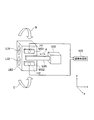
- 2 is a perspective view illustrating a schematic configuration of a holding frame and a drive unit of the imaging apparatus according to the embodiment.
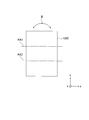
- 1 is a schematic configuration of a holding frame and a drive unit of an imaging apparatus according to an embodiment as viewed from an optical axis direction. It is a figure which shows the vertical shift of the left-right image in an image pick-up element surface. It is a figure which shows the rotation by the play of a holding frame.
- 1 is a diagram illustrating a schematic configuration of an imaging apparatus according to Embodiment 1.
- FIG. 1 is a diagram illustrating a schematic configuration of an imaging apparatus according to Embodiment 1.
- FIG. 1 is a diagram illustrating a lens cross-sectional configuration of an imaging apparatus according to Example 1.
- FIG. 3 is a diagram illustrating a schematic configuration of an imaging apparatus according to a second embodiment.
- 6 is a diagram illustrating a lens cross-sectional configuration of an imaging apparatus according to Example 2.
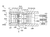
- FIG. 1A is a diagram illustrating a schematic configuration of the imaging apparatus 10 according to the first embodiment.
- the imaging apparatus 10 includes two parallel optical systems LNS1 and LNS2 that generate two optical images having parallax with each other, and an imaging element IMG that captures an optical image by the two optical systems LNS1 and LNS2.
- the movable lenses L31 and L32 that are arranged in the two optical systems LNS1 and LNS2, respectively, move in the optical axis AX1 and AX2 directions and change the focal position, and the two movable lenses L31 and L32.
- the holding frame LB2 is viewed from the directions of the optical axes AX1 and AX2.
- the outer shape is a non-circular shape, and the non-circular shape is a direction in which the length dy in the parallax direction (y direction in FIG. 3) of the two optical systems LNS1 and LNS2 is orthogonal to the parallax direction ( 3, wherein the x-direction) of a long shape than the length dx.
- the holding frame LB1 holds the lenses L1 and L2.
- the holding frame LB2 holds the lenses L31 and L32.
- the holding frame LB3 holds the aperture stop S, the lens L4, the parallel plate F1, and the lenses L5 and L6.
- the parallel flat plate F2, the parallel flat plate (cover glass) CG, and the image sensor IMG are joined.
- the holding frame LB4 holds the joined parallel plate F2, the parallel plate CG, and the imaging element IMG.
- the holding frames LB1, LB3, and LB4 are fixed.
- the holding frame LB2 has a fitting clearance so as to be movable in the arrow A direction with respect to the holding frame LB1.
- FIG. 1 the position which arrange
- the position where the driving unit 100 is disposed will be described later with reference to FIGS.
- the optical system LNS1 forms an image for the right eye
- the optical system LNS2 forms an image for the left eye.
- the optical image by the two optical systems LNS1 and LNS2 can be captured by the imaging element IMG.
- the optical system LNS1 has a movable lens L31 for moving in the direction of the optical axis AX1 to change the focal position.
- the optical system LNS2 includes a movable lens L32 that moves in the direction of the optical axis AX2 to change the focal position. This optical system can switch the object distance in focus without greatly changing the focal length. This makes it possible to perform close-up observation while maintaining a wide angle of view without greatly changing the angle of view.
- FIG. 2 is a perspective view showing a schematic configuration of the holding frame LB2 and the drive unit 100 of the imaging device 10.
- FIG. 3 shows a schematic configuration of the holding frame LB2 and the driving unit 100 of the imaging device 10 as viewed from the optical axes AX1 and AX2.
- One holding frame LB2 holds two movable lenses L31 and L32.
- one drive unit 100 moves the holding frame LB2 in the direction of the optical axes AX1 and AX2 via the drive frame LB5.
- the image pickup apparatus can be downsized by one drive unit 100.
- the movable lenses L31 and L32 are driven by the single holding frame LB2, the positional variation in the optical axes AX1 and AX2 directions of the two movable lenses L31 and L32 can be reduced.
- FIG. 5 is a diagram illustrating the rotation of the holding frame LB2 due to backlash.
- the holding frame LB2 rotates in the direction of arrow B in the yz plane in FIGS. 2 and 3 due to the fitting clearance.
- the movable lenses L31 and L32 are displaced in the positions of the optical axes AX1 and AX2. Therefore, in the two optical systems LNS1 and LNS2, a magnification shift between the left and right images occurs.
- the movable lenses L31 and L32 are held by one holding frame LB2. For this reason, it is possible to reduce the magnification shift between the left and right images.
- the holding frame LB2 is moved in the optical axis AX1, AX2 direction, that is, the arrow A direction by one driving unit 100. Since only one driving unit 100 is required, the apparatus can be reduced in size.
- the drive unit 100 can be configured by, for example, a voice coil motor.
- FIG. 4 is a diagram showing the vertical shift of the left and right images in the image sensor IMG.
- the right eye image R ′ and the left eye image L ′ are shifted in the vertical direction with respect to the right eye image R and the left eye image L without vertical displacement.
- the outer shape is a non-circular shape
- the non-circular shape is the parallax direction of the two optical systems LNS1 and LNS2 (FIG. 3, y direction).
- the non-circular shape of the holding frame LB2 is a rectangular shape.
- the outer diameter of the holding frame LB2 is, for example, a circular shape
- rotation in the direction of arrow C in FIGS. 2 and 3
- positions the drive part 100 mentioned later is securable by making holding frame LB2 non-circular shape.
- FIG. 2 there are at least two position sensors provided in the vicinity of the two movable lenses L31 and L32 and for detecting the position of the holding frame LB2. Based on the positional information in the optical axis AX1 and AX2 directions of the holding frame LB2 detected by the Hall elements H1 and H2 and the Hall elements H1 and H2, two optical images having parallax by the two optical systems LNS1 and LNS2 are obtained. And an image processing unit 102 for electrical correction.
- a hall element H1 is provided in the vicinity of the lens L31 of the holding frame LB2.
- a permanent magnet MG1 is provided at a position facing the hall element H1.
- the permanent magnet MG1 is fixed similarly to the fixed holding frames LB1, LB3, LB4. Thereby, the movement amount of the Hall element H1 can be detected based on the Hall output from the Hall element H1.
- a Hall element H2 is provided in the vicinity of the lens L32 of the holding frame LB2.
- a permanent magnet MG2 is provided at a position facing the hall element H2.
- the permanent magnet MG2 is fixed similarly to the fixed holding frames LB1, LB3, and LB4. Thereby, the movement amount of the Hall element H2 can be detected based on the Hall output from the Hall element H2.
- the position of the holding frame LB2 may fluctuate when the lenses L31 and L32 are driven due to the influence of the fitting clearance (backlash) between the holding frame LB1 and the holding frame LB2.
- deviation occurs in the directions of the optical axes AX1 and AX2 of the two Hall elements H1 and H2.
- the output signal from the image sensor IMG is input to the image processing unit 102 via the A / D conversion unit 101.
- the image processing unit 102 calculates such a shift amount based on the Hall output from the Hall element H1 and the Hall output from the Hall element H2. Then, the image processing unit 102 performs image processing for electrically correcting the magnification shift between the left and right images based on the calculated value.
- the display unit 103 displays the corrected image.
- one driving unit 100 is disposed in a direction (x direction) orthogonal to the parallax direction (y direction) of the two optical systems LNS1 and LNS2.
- the apparatus can be downsized.
- the space margin in the x direction of the holding frame LB2 can be effectively used, and thus the apparatus can be downsized.
- the drive unit when the drive unit is provided in the y direction of the parallax, the size of the imaging device in the y direction only becomes larger, so when the imaging device is arranged at the endoscope tip, the outer diameter of the endoscope tip is reduced. It becomes difficult.
- the drive unit if the drive unit is arranged between the two optical systems in the y direction, the parallax becomes large, and it is difficult to perform good stereoscopic observation.
- the above-described problem can be solved by arranging the driving unit 100 in a direction (x direction) orthogonal to the parallax direction.
- FIG. 1B is a diagram illustrating a schematic configuration of the imaging apparatus 20 according to the second embodiment.
- the same components as those in the first embodiment are denoted by the same reference numerals, and redundant description is omitted.
- the optical system LNS1 includes a movable lens CL1 that moves in the direction of the optical axis AX1 to change the focal length.
- the lens CL1 is configured by joining a lens L5 and a lens L6.
- the optical system LNS2 has a movable lens CL2 that moves in the direction of the optical axis AX2 to change the focal length.
- FIG. 6A is a diagram illustrating a schematic configuration of the imaging apparatus according to the present embodiment.
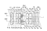
- FIG. 6B is a diagram illustrating a lens cross-sectional configuration of the imaging apparatus according to the present embodiment.
- This example includes two optical systems LNS1 and LNS2 that generate two optical images having parallax with each other.
- Each optical system includes, in order from the object side, a plano-concave negative lens L1 having a concave surface facing the image side, a negative meniscus lens L2 having a convex surface facing the image side, and a positive meniscus lens L31 (with a convex surface facing the object side).
- L32) aperture stop S, biconvex positive lens L4, parallel flat plate F1, biconvex positive lens L5, negative meniscus lens L6 with a convex surface facing the image side, parallel flat plate F2, and parallel flat plate CG.
- the image sensor IMG the image sensor IMG.
- the negative lens L1 is composed of an integral member with respect to the optical system LNS1 and the optical system LNS2.
- the positive lens L5 and the negative meniscus lens L6 are cemented.
- the parallel plate F2, the parallel plate CG, and the image sensor IMG are joined.
- the holding frame LB1 holds the negative lens L1 and the negative meniscus lens L2.
- the holding frame LB2 holds the positive meniscus lenses L31 and L32.
- the holding frame LB3 holds the aperture stop S, the positive lens L4, the parallel flat plate F1, the positive lens L5, and the negative meniscus lens L6.
- the holding frame LB4 holds the parallel flat plate F2, the parallel flat plate CG, and the image sensor IMG.
- the holding frames LB1, LB3, and LB4 are fixed.
- the holding frame LB2 has a fitting clearance so as to be movable with respect to the holding frame LB1.
- the optical system LNS1 forms an image for the right eye
- the optical system LNS2 forms an image for the left eye.
- the optical image by the two optical systems LNS1 and LNS2 can be captured by the imaging element IMG.
- the optical system LNS1 has a movable lens L31 that moves in the direction of the optical axis AX1 to change the focal position.
- the optical system LNS2 includes a movable lens L32 that moves in the direction of the optical axis AX2 to change the focal position.
- FIG. 7A is a diagram illustrating a schematic configuration of the imaging apparatus according to the present embodiment.
- FIG. 7B is a diagram illustrating a lens cross-sectional configuration of the imaging apparatus according to the present embodiment.
- This example includes two optical systems LNS1 and LNS2 that generate two optical images having parallax with each other.
- Each optical system includes, in order from the object side, a plano-concave negative lens L1 having a concave surface facing the image side, a parallel flat plate F1, a positive meniscus lens L2 having a convex surface facing the image side, a biconvex positive lens L3, A negative meniscus lens L4 having a convex surface facing the image side, an aperture stop S, a plano-concave negative lens L5 having a concave surface facing the image side, a positive meniscus lens L6 having a convex surface facing the object side, and a biconvex positive lens L7, a biconvex positive lens L8, a negative meniscus lens L9 having a convex surface facing the image side, a parallel plate F2, two parallel plates CG, and an image sensor IMG.
- the negative lens L1 is composed of an integral member with respect to the optical system LNS1 and the optical system LNS2.
- the positive lens L3 and the negative meniscus lens L4 are cemented.
- the negative lens L5 and the positive meniscus lens L6 are cemented to form a lens CL1 (CL2).
- the positive lens L8 and the negative meniscus lens L9 are cemented.
- Two parallel flat plates CG and the image sensor IMG are joined.
- the holding frame LB1 holds the negative lens L1, the parallel plate F1, the positive meniscus lens L2, the positive lens L3, and the negative meniscus lens L4.
- the holding frame LB2 holds the negative lens L5 and the positive meniscus lens L6.
- the holding frame LB3 holds the positive lens L7, the positive lens L8, and the negative meniscus lens L9.
- the holding frame LB4 holds the parallel flat plate F2, the two parallel flat plates CG, and the image sensor IMG.
- the holding frames LB1, LB3, and LB4 are fixed.
- the holding frame LB2 has a fitting clearance so as to be movable with respect to the holding frame LB1.
- the optical system LNS1 forms an image for the right eye
- the optical system LNS2 forms an image for the left eye.
- the optical image by the two optical systems LNS1 and LNS2 can be captured by the imaging element IMG.
- the optical system LNS1 has a movable lens CL1 that moves in the direction of the optical axis AX1 to change the focal length.
- the lens CL1 is configured by joining a lens L5 and a lens L6.
- the optical system LNS2 has a movable lens CL2 that moves in the direction of the optical axis AX2 to change the focal length.
- the present invention is useful for an imaging apparatus that is small and can perform good stereoscopic observation.
- the present invention can be modified.
- the image processing unit that electrically corrects the optical image may correct the vertical shift of the images by correcting the positions of the two images based on the values of the two position sensors.
- the optical system is not limited to two independent optical systems as in the above-described embodiments.
- L1 may have a concave shape instead of two concave shapes, and may be configured to be shared by two optical systems.
Landscapes
- Physics & Mathematics (AREA)
- General Physics & Mathematics (AREA)
- Engineering & Computer Science (AREA)
- Multimedia (AREA)
- Signal Processing (AREA)
- Optics & Photonics (AREA)
- Testing, Inspecting, Measuring Of Stereoscopic Televisions And Televisions (AREA)
- Studio Devices (AREA)
Abstract
小型で、良好な立体観察を行うことができる撮像装置を提供すること。 互いに視差を有する2つの光学像を生成する並列する2つの光学系LNS1、LNS2と、2つの光学系LNS1、LNS2による光学像を撮像する撮像素子IMGと、を有する撮像装置10であって、2つ光学系LNS1、LNS2のそれぞれに配置され、光軸方向AX1、AX2に移動して焦点位置を変更するための可動なレンズL31、L32と、2つの可動なレンズL31、L32を保持するための1つの保持枠LB2と、保持枠LB2を光軸AX1、AX2方向に移動するための1つの駆動部100と、を有し、保持枠LB2を光軸AX1、AX2方向から見た時の外形は、非円形形状であり、非円形形状は、2つの光学系LNS1、LNS2の視差方向(図3、y方向)の長さが、視差方向(図3、x方向)に直交する方向の長さdxよりも長い形状であることを特徴とする。
Description
本発明は、撮像装置に関するものである。
従来、立体観察システムが知られている。立体観察システムは、立体視用に視差の異なる2つの画像を略同一の平面上、例えば1つの撮像素子の撮像面に結像させて撮像する方法を用いる。そして、従来技術の構成では、視差の異なる2つの画像を得るために、2つの異なる光学系を有している。
このような立体観察システムは、左目用、右目用の光学系を用いている。左目用光学系と、右目用光学系とで視差のある画像を撮像する。視差のある画像を人間が頭の中で認識することで、距離感が得られ、立体的に観察されることとなる。立体観察システム、特に内視鏡用の立体観察システムが特許文献1、2、3に提案されている。
立体観察システムにおいては、光学系を構成するレンズのうち、一部のレンズを光軸に沿って移動することで焦点距離を可変とすることが望ましい。このため、移動するレンズの保持枠と、他の固定しているレンズの保持枠との間に、嵌合クリアランスを設けている。
嵌合クリアランスにより、移動するレンズの保持枠において、ガタが発生する場合がある。ガタが発生すると、左眼用画像と、右目用画像との間において、倍率のズレ、上下方向のズレ、左右方向のズレを生じるため、良好な立体観察を行うことが困難となる。
特許文献1、2の構成では、このようなガタによる左目画像と右目画像のズレを効果的に低減することは困難である。また、特許文献3では、左目画像と右目画像の倍率の差を検出して、補正している。この構成では、装置が大型化してしまうという問題がある。
本発明は、上記に鑑みてなされたものであって、小型で、良好な立体観察を行うことができる撮像装置を提供することを目的とする。
上述した課題を解決し、目的を達成するために、本発明の少なくとも幾つかの実施形態に係る撮像装置は、互いに視差を有する2つの光学像を生成する並列する2つの光学系と、2つの光学系による光学像を撮像する撮像素子と、を有する撮像装置であって、2つ光学系のそれぞれに配置され、光軸方向に移動して焦点位置を変更するための可動レンズと、2つの可動なレンズを保持するための1つの保持枠と、保持枠を光軸方向に移動するための1つの駆動部と、を有し、保持枠を光軸方向から見た時の外形は、非円形形状であり、非円形形状は、2つの光学系の視差方向の長さが、視差方向に直交する方向の長さよりも長い形状であることを特徴とする。
本発明には、小型で、良好な立体観察を行うことができる撮像装置を提供できるという効果を奏する。
以下に、実施形態に係る撮像装置を図面に基づいて詳細に説明する。なお、この実施形態により、この発明が限定されるものではない。
(第1実施形態)
図1Aは、第1実施形態に係る撮像装置10の概略構成を示す図である。本実施形態は、互いに視差を有する2つの光学像を生成する並列する2つの光学系LNS1、LNS2と、2つの光学系LNS1、LNS2による光学像を撮像する撮像素子IMGと、を有する撮像装置10であって、2つ光学系LNS1、LNS2のそれぞれに配置され、光軸AX1、AX2方向に移動して焦点位置を変更するための可動なレンズL31、L32と、2つの可動なレンズL31、L32を保持するための1つの保持枠LB2と、保持枠LB2を光軸AX1、AX2方向に移動するための1つの駆動部100と、を有し、保持枠LB2を光軸AX1、AX2方向から見た時の外形は、非円形形状であり、非円形形状は、2つの光学系LNS1、LNS2の視差方向(図3、y方向)の長さdyが、視差方向に直交する方向(図3、x方向)の長さdxよりも長い形状であることを特徴とする。
図1Aは、第1実施形態に係る撮像装置10の概略構成を示す図である。本実施形態は、互いに視差を有する2つの光学像を生成する並列する2つの光学系LNS1、LNS2と、2つの光学系LNS1、LNS2による光学像を撮像する撮像素子IMGと、を有する撮像装置10であって、2つ光学系LNS1、LNS2のそれぞれに配置され、光軸AX1、AX2方向に移動して焦点位置を変更するための可動なレンズL31、L32と、2つの可動なレンズL31、L32を保持するための1つの保持枠LB2と、保持枠LB2を光軸AX1、AX2方向に移動するための1つの駆動部100と、を有し、保持枠LB2を光軸AX1、AX2方向から見た時の外形は、非円形形状であり、非円形形状は、2つの光学系LNS1、LNS2の視差方向(図3、y方向)の長さdyが、視差方向に直交する方向(図3、x方向)の長さdxよりも長い形状であることを特徴とする。
保持枠LB1は、レンズL1、L2を保持する。保持枠LB2は、レンズL31、L32を保持する。保持枠LB3は、明るさ絞りSと、レンズL4と、平行平板F1と、レンズL5、L6と、を保持する。平行平板F2と、平行平板(カバーガラス)CGと、撮像素子IMGと、は接合されている。保持枠LB4は、接合された平行平板F2と、平行平板CGと、撮像素子IMGと、を保持する。保持枠LB1、LB3、LB4は、それぞれ固定している。保持枠LB2は、保持枠LB1に対して矢印A方向に移動可能なように嵌合クリアランスを有している。
なお、図1において、駆動部100を配置する位置は、模式的に示している。駆動部100を配置する位置は、図2、図3を用いて後述する。
例えば、光学系LNS1は右眼用の画像を結像し、光学系LNS2は左眼用の画像を結像する。これにより、撮像素子IMGにより、2つの光学系LNS1、LNS2による光学像を撮像できる。
光学系LNS1は、光軸AX1方向に移動して焦点位置を変更するための可動なレンズL31を有する。光学系LNS2は、光軸AX2方向に移動して焦点位置を変更するための可動なレンズL32を有する。この光学系は、焦点距離を大きく変化させることなく、ピントが合う物点距離を切り替えることができる。これにより、画角を大きく変化させずに、広い画角のままで、近接観察が可能となる。
図2は、撮像装置10の保持枠LB2と駆動部100との概略構成を示す斜視図である。図3は、撮像装置10の保持枠LB2と駆動部100とを光軸AX1、AX2から見た概略構成を示すである。1つの保持枠LB2は、2つの可動なレンズL31、L32を保持している。また、1つの駆動部100は、駆動枠LB5を介して、保持枠LB2を光軸AX1、AX2方向に移動する。このように、1つの駆動部100により、撮像装置を小型化できる。また、1つの保持枠LB2で、可動なレンズL31、L32を駆動しているため、2つの可動なレンズL31、L32の光軸AX1、AX2方向の位置バラツキを低減できる。
左右画像の倍率ズレについて説明する。図5は、保持枠LB2のガタによる回転を示す図である。
嵌合クリアランスにより、保持枠LB2が、図2、図3におけるy-z面内において矢印B方向に回転する場合を考える。この場合、可動レンズL31とL32は、光軸AX1、AX2方向の位置がずれる。よって、2つの光学系LNS1、LNS2において、左右画像の倍率ズレが生ずる。
本実施形態では、1つの保持枠LB2で可動なレンズL31、L32を保持している。このため、左右画像の倍率ズレを低減できる。
また、1つの駆動部100により、保持枠LB2を光軸AX1、AX2方向、即ち矢印A方向に移動する。駆動部100が1つで良いため、装置を小型化できる。駆動部100は、例えばボイスコイルモータで構成できる。
次に、左右画像の上下ズレについて説明する。図2におけるx-y面内において矢印C方向に回転する場合を考える。この場合、可動レンズL31とL32は、光軸に対して垂直な方向に偏芯する。よって、撮像素子IMGにおいて、右目画像と左目画像に関して、上下ズレが生ずる。
図4は、撮像素子IMGにおける左右画像の上下ズレを示す図である。上下ズレの無い右目画像R、左目画像Lに対して、右目画像R’、左目画像L’はそれぞれ上下方向にシフトしている。
本実施形態は、保持枠LB2を光軸AX1、AX2方向から見た時の外形は、非円形形状であり、非円形形状は、2つの光学系LNS1、LNS2の視差方向(図3、y方向)の長さdyが、視差方向に直交する方向(図3、x方向)の長さdxよりも長い形状である。本実施形態では、保持枠LB2の非円形形状は、矩形形状である。なお、この形状に限られるものではなく、楕円形状、多角形形状でも良い。
保持枠LB2の外径が、例えば円形形状である場合、機械的な制約が少ないため、保持枠が光軸回りに回転しやすくなってしまう。本実施形態では、保持枠LB2の外径の長さdy>dxとしている。例えば、長さdyの面を、対向する部材(不図示)で受けることにより、上下ズレの原因となる回転(図2、図3の矢印C方向)を低減できる。また、保持枠LB2を非円形形状とすることで、後述する駆動部100を配置する空間的領域を確保することができる。
なお、保持枠LB2に2つの可動なレンズL31、L32を固定しているために、勘合クリアランス(ガタ)があっても、左右画像の左右ズレは原理的に発生しない。
また、本実施形態の好ましい態様によれば、図2に示すように、2つの可動なレンズL31、L32の近傍に設けられ、保持枠LB2の位置を検出するための少なくとも2つの位置センサーであるホール素子H1、H2と、ホール素子H1、H2により検出された保持枠LB2の光軸AX1、AX2方向の位置情報に基づいて、2つの光学系LNS1、LNS2による互いに視差を有する2つの光学像を電気的に補正する画像処理部102と、を有する。
図2、図3に示すように、保持枠LB2のレンズL31近傍にホール素子H1が設けられている。ホール素子H1に対向する位置に永久磁石MG1が設けられている。永久磁石MG1は、固定された保持枠LB1、LB3、LB4と同様に、固定されている。これにより、ホール素子H1からのホール出力に基づいて、ホール素子H1の移動量を検出できる。
また、保持枠LB2のレンズL32近傍にホール素子H2が設けられている。ホール素子H2に対向する位置に永久磁石MG2が設けられている。永久磁石MG2は、固定された保持枠LB1、LB3、LB4と同様に、固定されている。これにより、ホール素子H2からのホール出力に基づいて、ホール素子H2の移動量を検出できる。
保持枠LB1と保持枠LB2との間の勘合クリアランス(ガタ)の影響で、レンズL31、L32の駆動時に、保持枠LB2の位置が変動する場合がある。特に、上述したような倍率ズレが発生する回転モードでは、2つのホール素子H1、H2の光軸AX1、AX2の方向にズレが生じる。
撮像素子IMGからの出力信号は、A/D変換部101を介して、画像処理部102に入力する。画像処理部102は、ホール素子H1からのホール出力と、ホール素子H2からのホール出力に基づいて、このようなズレ量を算出する。そして、画像処理部102は、算出値を元に、左右画像の倍率ズレを電気的に補正する画像処理を行う。そして、表示部103は、補正された画像を表示する。
また、本実施形態の好ましい態様によれば、一つの駆動部100は、2つの光学系LNS1、LNS2の視差方向(y方向)に直交する方向(x方向)に配置されていることが望ましい。まず、駆動部100が1つであることで装置の小型が可能である。また、駆動部100を視差方向と直交する方向(x方向)に配置することにより、保持枠LB2のx方向の空間的余裕を効果的に利用できるため、装置の小型化が可能となる。例えば、視差のy方向に駆動部を有すると、y方向のみの撮像装置サイズがより大きくなるため、内視鏡先端に撮像装置を配置する際に、内視鏡先端外径を小型化することが困難となる。また、y方向で2つの光学系の間に駆動部を配置すると、視差が大きくなってしまうため、良好な立体観察が困難となる。以上により、本実施形態では、駆動部100を視差方向と直交する方向(x方向)に配置することで、上述の課題を解決することができる。尚、本実施例では、x=0の位置に配置しているが、y方向の撮像サイズが変化しない範囲で、駆動部のxの位置を変更しても良い。
(第2実施形態)
図1Bは、第2実施形態に係る撮像装置20の概略構成を示す図である。第1実施形態と同様の構成には、同一の参照符号を付し、重複する説明は省略する。
図1Bは、第2実施形態に係る撮像装置20の概略構成を示す図である。第1実施形態と同様の構成には、同一の参照符号を付し、重複する説明は省略する。
第1実施形態と異なり、本実施形態では、光学系LNS1は、光軸AX1方向に移動して焦点距離を変更するための可動なレンズCL1を有する。レンズCL1は、レンズL5とレンズL6とを接合して構成される。光学系LNS2は、光軸AX2方向に移動して焦点距離を変更するための可動なレンズCL2を有する。これにより、拡大観察時には、焦点距離を長く(画角を狭く)、ピントが合う物点距離を短く設定できるため、より拡大した観察が可能となる。
このような、ズーム光学系においても、上記第1実施形態で述べた構成を有することで、第1実施形態に係る撮像装置10と同じ効果を奏することができる。
(実施例1)
実施例1に係る撮像装置について説明する。図6Aは、本実施例に係る撮像装置の概略構成を示す図である。図6Bは、本実施例に係る撮像装置のレンズ断面構成を示す図である。
実施例1に係る撮像装置について説明する。図6Aは、本実施例に係る撮像装置の概略構成を示す図である。図6Bは、本実施例に係る撮像装置のレンズ断面構成を示す図である。
本実施例は、互いに視差を有する2つの光学像を生成する、2つの光学系LNS1、光学系LNS2を有する。それぞれの光学系は、物体側から順に、像側に凹面を向けた平凹負レンズL1と、像側に凸面を向けた負メニスカスレンズL2と、物体側に凸面を向けた正メニスカスレンズL31(L32)と、明るさ絞りSと、両凸正レンズL4と、平行平板F1と、両凸正レンズL5と、像側に凸面を向けた負メニスカスレンズL6と、平行平板F2と、平行平板CGと、撮像素子IMGと、から構成される。
負レンズL1は、光学系LNS1と光学系LNS2とに対して一体の部材で構成されている。正レンズL5と、負メニスカスレンズL6と、は接合されている。平行平板F2と、平行平板CGと、撮像素子IMGと、は接合されている。
保持枠LB1は、負レンズL1と、負メニスカスレンズL2と、を保持する。保持枠LB2は、正メニスカスレンズL31、L32を保持する。保持枠LB3は、明るさ絞りSと、正レンズL4と、平行平板F1と、正レンズL5と、負メニスカスレンズL6と、を保持する。保持枠LB4は、平行平板F2と、平行平板CGと、撮像素子IMGと、を保持する。保持枠LB1、LB3、LB4は、それぞれ固定している。保持枠LB2は、保持枠LB1に対して移動可能であるように嵌合クリアランスを有している。
例えば、光学系LNS1は右眼用の画像を結像し、光学系LNS2は左眼用の画像を結像する。これにより、撮像素子IMGにより、2つの光学系LNS1、LNS2による光学像を撮像できる。
また、光学系LNS1は、光軸AX1方向に移動して焦点位置を変更するための可動なレンズL31を有する。光学系LNS2は、光軸AX2方向に移動して焦点位置を変更するための可動なレンズL32を有する。これにより、画角の変化が少ない状態で、ピントが合う物点距離を切替えることができる。
(実施例2)
実施例2に係る撮像装置について説明する。図7Aは、本実施例に係る撮像装置の概略構成を示す図である。図7Bは、本実施例に係る撮像装置のレンズ断面構成を示す図である。
実施例2に係る撮像装置について説明する。図7Aは、本実施例に係る撮像装置の概略構成を示す図である。図7Bは、本実施例に係る撮像装置のレンズ断面構成を示す図である。
本実施例は、互いに視差を有する2つの光学像を生成する、2つの光学系LNS1、光学系LNS2を有する。それぞれの光学系は、物体側から順に、像側に凹面を向けた平凹負レンズL1と、平行平板F1と、像側に凸面を向けた正メニスカスレンズL2と、両凸正レンズL3と、像側に凸面を向けた負メニスカスレンズL4と、明るさ絞りSと、像側に凹面を向けた平凹負レンズL5と、物体側に凸面を向けた正メニスカスレンズL6と、両凸正レンズL7と、両凸正レンズL8と、像側に凸面を向けた負メニスカスレンズL9と、平行平板F2と、2枚の平行平板CGと、撮像素子IMGと、から構成される。
負レンズL1は、光学系LNS1と光学系LNS2とに対して一体の部材で構成されている。正レンズL3と、負メニスカスレンズL4と、は接合されている。負レンズL5と、正メニスカスレンズL6と、は接合されて、レンズCL1(CL2)を構成する。正レンズL8と、負メニスカスレンズL9と、は接合されている。2枚の平行平板CGと、撮像素子IMGと、は接合されている。
保持枠LB1は、負レンズL1と、平行平板F1と、正メニスカスレンズL2と、正レンズL3と、負メニスカスレンズL4と、を保持する。保持枠LB2は、負レンズL5と、正メニスカスレンズL6と、を保持する。保持枠LB3は、正レンズL7と、正レンズL8と、負メニスカスレンズL9と、を保持する。保持枠LB4は、平行平板F2と、2枚の平行平板CGと、撮像素子IMGと、を保持する。保持枠LB1、LB3、LB4は、それぞれ固定している。保持枠LB2は、保持枠LB1に対して移動可能であるように嵌合クリアランスを有している。
例えば、光学系LNS1は右眼用の画像を結像し、光学系LNS2は左眼用の画像を結像する。これにより、撮像素子IMGにより、2つの光学系LNS1、LNS2による光学像を撮像できる。
実施例1と異なり、本実施例では、光学系LNS1は、光軸AX1方向に移動して焦点距離を変更するための可動なレンズCL1を有する。レンズCL1は、レンズL5とレンズL6とを接合して構成される。光学系LNS2は、光軸AX2方向に移動して焦点距離を変更するための可動なレンズCL2を有する。これにより、画角を変化させて、焦点距離を可変とするズーム光学系とすることができる。
以下に、上記各実施例の数値データを示す。記号は、rは各レンズ面の曲率半径、dは各レンズ面間の間隔、ndは各レンズのd線の屈折率(数値実施例1)、neは各レンズのe線の屈折率(数値実施例2)、νdは各レンズのアッベ数である。また、Sは明るさ絞りである。
数値実施例1
単位 mm
面データ
面番号 r d nd νd
1 ∞ 0.2500 1.88815 40.76
2 0.592 0.6331
3 -0.9641 0.4900 1.85504 23.78
4 -1.1345 可変
5 2.11 0.3917 1.58482 40.75
6 12.2107 可変
7(S) ∞ 0.0610
8 22.4495 0.5905 1.57124 56.36
9 -1.9442 0.0500
10 ∞ 0.4000 1.49557 75.00
11 ∞ 0.0656
12 1.3335 0.7598 1.69979 55.53
13 -0.8346 0.2798 1.93429 18.90
14 -3.6567 0.2520
15 ∞ 0.5000 1.51825 64.14
16 ∞ 0.3500 1.50700 63.26
撮像面 ∞
各種データ 通常観察 拡大観察
焦点距離 0.426 0.396
Fno 3.04 3.09
物点距離 9.3 1.6
d4 0.39 0.69
d6 0.36 0.06
単位 mm
面データ
面番号 r d nd νd
1 ∞ 0.2500 1.88815 40.76
2 0.592 0.6331
3 -0.9641 0.4900 1.85504 23.78
4 -1.1345 可変
5 2.11 0.3917 1.58482 40.75
6 12.2107 可変
7(S) ∞ 0.0610
8 22.4495 0.5905 1.57124 56.36
9 -1.9442 0.0500
10 ∞ 0.4000 1.49557 75.00
11 ∞ 0.0656
12 1.3335 0.7598 1.69979 55.53
13 -0.8346 0.2798 1.93429 18.90
14 -3.6567 0.2520
15 ∞ 0.5000 1.51825 64.14
16 ∞ 0.3500 1.50700 63.26
撮像面 ∞
各種データ 通常観察 拡大観察
焦点距離 0.426 0.396
Fno 3.04 3.09
物点距離 9.3 1.6
d4 0.39 0.69
d6 0.36 0.06
数値実施例2
単位 mm
面番号 r d ne νd
1 ∞ 0.38 1.88815 40.76
2 1.363 0.85
3 ∞ 0.31 1.51564 75.00
4 ∞ 1.45
5 -5.355 1.05 1.65222 33.79
6 -2.355 0.03
7 4.019 0.98 1.77621 49.60
8 -3.296 0.30 1.93429 18.90
9 -19.843 可変
10(S) ∞ 0.01
11 ∞ 0.28 1.48915 70.23
12 1.455 0.38 1.59667 35.31
13 1.912 可変
14 3.915 1.52 1.48915 70.23
15 -3.915 0.04
16 13.704 1.54 1.48915 70.23
17 -2.584 0.42 1.93429 18.90
18 -6.244 0.52
19 ∞ 0.40 1.52498 59.89
20 ∞ 0.65
21 ∞ 0.80 1.51825 64.14
22 ∞ 0.80 1.50801 60.00
23(撮像面) ∞
各種データ 通常観察 中間 拡大観察
焦点距離 1.70 1.8 1.85
Fno 7.09 8.09 8.15
物点距離 18.0 4.0 2.0
d9 0.32 0.85 1.38
d13 1.64 1.11 0.58
単位 mm
面番号 r d ne νd
1 ∞ 0.38 1.88815 40.76
2 1.363 0.85
3 ∞ 0.31 1.51564 75.00
4 ∞ 1.45
5 -5.355 1.05 1.65222 33.79
6 -2.355 0.03
7 4.019 0.98 1.77621 49.60
8 -3.296 0.30 1.93429 18.90
9 -19.843 可変
10(S) ∞ 0.01
11 ∞ 0.28 1.48915 70.23
12 1.455 0.38 1.59667 35.31
13 1.912 可変
14 3.915 1.52 1.48915 70.23
15 -3.915 0.04
16 13.704 1.54 1.48915 70.23
17 -2.584 0.42 1.93429 18.90
18 -6.244 0.52
19 ∞ 0.40 1.52498 59.89
20 ∞ 0.65
21 ∞ 0.80 1.51825 64.14
22 ∞ 0.80 1.50801 60.00
23(撮像面) ∞
各種データ 通常観察 中間 拡大観察
焦点距離 1.70 1.8 1.85
Fno 7.09 8.09 8.15
物点距離 18.0 4.0 2.0
d9 0.32 0.85 1.38
d13 1.64 1.11 0.58
以上のように、本発明は、小型で、良好な立体観察を行うことができる撮像装置に有用である。また、本発明は変形が可能である。例えば、光学像を電気的に補正する画像処理部は、2つの位置センサーの値を元に、2つの画像の位置補正を行い、画像の上下ズレを対策してもよい。さらに、光学系は上述の実施例のように2つの独立した光学系だけに限らない。例えば、L1は2つの凹面形状ではなく、1つの凹面形状とし、2つの光学系で共有する構成としても良い。
LNS1 光学系
LNS2 光学系
LB1、LB2、LB3、LB4 保持枠
L31、L32、CL1、CL2 可動なレンズ
LB5 駆動枠
IMG 撮像素子
I 像面(撮像面)
L1~L9 レンズ
F1、F2、CG 平行平板
S 明るさ絞り
H1、H2 ホール素子
MG1、MG2 永久磁石
10、20 撮像装置
100 駆動部
101 A/D変換部
102 画像処理部
103 表示部
LNS2 光学系
LB1、LB2、LB3、LB4 保持枠
L31、L32、CL1、CL2 可動なレンズ
LB5 駆動枠
IMG 撮像素子
I 像面(撮像面)
L1~L9 レンズ
F1、F2、CG 平行平板
S 明るさ絞り
H1、H2 ホール素子
MG1、MG2 永久磁石
10、20 撮像装置
100 駆動部
101 A/D変換部
102 画像処理部
103 表示部
Claims (3)
- 互いに視差を有する2つの光学像を生成する並列する2つの光学系と、前記2つの光学系による光学像を撮像する撮像素子と、を有する撮像装置であって、
前記2つ光学系のそれぞれに配置され、光軸方向に移動して焦点位置を変更するための可動なレンズと、
前記2つの可動なレンズを保持するための1つの保持枠と、
前記保持枠を光軸方向に移動するための1つの駆動部と、を有し、
前記保持枠を光軸方向から見た時の外形は、非円形形状であり、
前記非円形形状は、前記2つの光学系の視差方向の長さが、前記視差方向に直交する方向の長さよりも長い形状であることを特徴とする撮像装置。 - 前記2つの可動なレンズの近傍に設けられ、前記保持枠の位置を検出するための少なくとも2つの位置センサーと、
前記位置センサーにより検出された前記保持枠の光軸方向の位置情報に基づいて、前記2つの光学系による前記互いに視差を有する2つの光学像を電気的に補正する画像処理部と、を有することを特徴とする請求項1に記載の撮像装置。 - 前記一つの駆動部は、前記2つの光学系の視差方向に直交する方向に配置されていることを特徴とする請求項1または2に記載の撮像装置。
Applications Claiming Priority (2)
| Application Number | Priority Date | Filing Date | Title |
|---|---|---|---|
| JP2016-097735 | 2016-05-16 | ||
| JP2016097735 | 2016-05-16 |
Publications (1)
| Publication Number | Publication Date |
|---|---|
| WO2017199666A1 true WO2017199666A1 (ja) | 2017-11-23 |
Family
ID=60324948
Family Applications (1)
| Application Number | Title | Priority Date | Filing Date |
|---|---|---|---|
| PCT/JP2017/015570 Ceased WO2017199666A1 (ja) | 2016-05-16 | 2017-04-18 | 撮像装置 |
Country Status (1)
| Country | Link |
|---|---|
| WO (1) | WO2017199666A1 (ja) |
Cited By (1)
| Publication number | Priority date | Publication date | Assignee | Title |
|---|---|---|---|---|
| WO2020017089A1 (ja) * | 2018-07-20 | 2020-01-23 | オリンパス株式会社 | 撮像ユニット、内視鏡および内視鏡システム |
Citations (4)
| Publication number | Priority date | Publication date | Assignee | Title |
|---|---|---|---|---|
| JPH08317424A (ja) * | 1995-05-19 | 1996-11-29 | Olympus Optical Co Ltd | 立体撮影装置 |
| JP2005058374A (ja) * | 2003-08-08 | 2005-03-10 | Olympus Corp | 立体内視鏡装置 |
| JP2006162991A (ja) * | 2004-12-07 | 2006-06-22 | Fuji Photo Film Co Ltd | 立体画像撮影装置 |
| JP2013521941A (ja) * | 2010-03-12 | 2013-06-13 | ヴァイキング・システムズ・インコーポレーテッド | 立体的可視化システム |
-
2017
- 2017-04-18 WO PCT/JP2017/015570 patent/WO2017199666A1/ja not_active Ceased
Patent Citations (4)
| Publication number | Priority date | Publication date | Assignee | Title |
|---|---|---|---|---|
| JPH08317424A (ja) * | 1995-05-19 | 1996-11-29 | Olympus Optical Co Ltd | 立体撮影装置 |
| JP2005058374A (ja) * | 2003-08-08 | 2005-03-10 | Olympus Corp | 立体内視鏡装置 |
| JP2006162991A (ja) * | 2004-12-07 | 2006-06-22 | Fuji Photo Film Co Ltd | 立体画像撮影装置 |
| JP2013521941A (ja) * | 2010-03-12 | 2013-06-13 | ヴァイキング・システムズ・インコーポレーテッド | 立体的可視化システム |
Cited By (5)
| Publication number | Priority date | Publication date | Assignee | Title |
|---|---|---|---|---|
| WO2020017089A1 (ja) * | 2018-07-20 | 2020-01-23 | オリンパス株式会社 | 撮像ユニット、内視鏡および内視鏡システム |
| CN112512395A (zh) * | 2018-07-20 | 2021-03-16 | 奥林巴斯株式会社 | 摄像单元、内窥镜以及内窥镜系统 |
| JPWO2020017089A1 (ja) * | 2018-07-20 | 2021-08-02 | オリンパス株式会社 | 撮像ユニット、内視鏡および内視鏡システム |
| JP7181294B2 (ja) | 2018-07-20 | 2022-11-30 | オリンパス株式会社 | 撮像ユニット、内視鏡および内視鏡システム |
| US11717138B2 (en) | 2018-07-20 | 2023-08-08 | Olympus Corporation | Imaging unit, endoscope and endoscope system having optical systems with overlapping depth of fields |
Similar Documents
| Publication | Publication Date | Title |
|---|---|---|
| US20100208046A1 (en) | Stereoscopic optical system, and optical apparatus for stereoscopic measurement, stereoscopic measurement apparatus and stereoscopic observation apparatus each using the same | |
| CN202548526U (zh) | 立体图像拍摄装置 | |
| US7388719B2 (en) | Camera system | |
| JP6307666B2 (ja) | 撮像装置 | |
| CN105917263A (zh) | 光学系统、立体摄像装置和内窥镜 | |
| WO2012017684A1 (ja) | レンズユニット | |
| CN105589192A (zh) | 光学系统、观察光学系统以及光学装置 | |
| US10674136B2 (en) | Device for capturing a stereoscopic image | |
| JP2014174390A (ja) | 結像光学系、立体撮像装置、及び内視鏡 | |
| US11968350B2 (en) | Lens apparatus and image pickup apparatus | |
| US10105034B2 (en) | Endoscope apparatus | |
| JP2018148383A (ja) | 撮像装置および撮像ユニット | |
| CN105793756B (zh) | 立体摄像光学系统、立体摄像装置以及内窥镜 | |
| WO2017033234A1 (ja) | 撮像装置 | |
| JPWO2019187221A1 (ja) | レンズ系、撮像装置及び撮像システム | |
| JP6072381B1 (ja) | 撮像装置 | |
| JP5629996B2 (ja) | 立体視光学装置および結像光学装置 | |
| WO2017199666A1 (ja) | 撮像装置 | |
| JP2016095490A (ja) | 光学系、観察光学系および光学装置 | |
| JP5390865B2 (ja) | 立体画像撮影装置 | |
| JP2011227306A (ja) | 複眼カメラ | |
| JP4970798B2 (ja) | 立体画像観察装置 | |
| EP4082420A1 (en) | Rigid mirror device | |
| WO2014168110A1 (ja) | 撮像装置 | |
| JP2010191325A (ja) | 撮影装置 |
Legal Events
| Date | Code | Title | Description |
|---|---|---|---|
| NENP | Non-entry into the national phase |
Ref country code: DE |
|
| 121 | Ep: the epo has been informed by wipo that ep was designated in this application |
Ref document number: 17799098 Country of ref document: EP Kind code of ref document: A1 |
|
| 122 | Ep: pct application non-entry in european phase |
Ref document number: 17799098 Country of ref document: EP Kind code of ref document: A1 |
|
| NENP | Non-entry into the national phase |
Ref country code: JP |