WO2017199633A1 - Imaging lens and imaging device - Google Patents
Imaging lens and imaging device Download PDFInfo
- Publication number
- WO2017199633A1 WO2017199633A1 PCT/JP2017/014504 JP2017014504W WO2017199633A1 WO 2017199633 A1 WO2017199633 A1 WO 2017199633A1 JP 2017014504 W JP2017014504 W JP 2017014504W WO 2017199633 A1 WO2017199633 A1 WO 2017199633A1
- Authority
- WO
- WIPO (PCT)
- Prior art keywords
- lens
- imaging
- optical axis
- vicinity
- refractive power
- Prior art date
Links
Images


Classifications
-
- G—PHYSICS
- G02—OPTICS
- G02B—OPTICAL ELEMENTS, SYSTEMS OR APPARATUS
- G02B13/00—Optical objectives specially designed for the purposes specified below
- G02B13/001—Miniaturised objectives for electronic devices, e.g. portable telephones, webcams, PDAs, small digital cameras
- G02B13/0015—Miniaturised objectives for electronic devices, e.g. portable telephones, webcams, PDAs, small digital cameras characterised by the lens design
- G02B13/002—Miniaturised objectives for electronic devices, e.g. portable telephones, webcams, PDAs, small digital cameras characterised by the lens design having at least one aspherical surface
- G02B13/0045—Miniaturised objectives for electronic devices, e.g. portable telephones, webcams, PDAs, small digital cameras characterised by the lens design having at least one aspherical surface having five or more lenses
-
- G—PHYSICS
- G02—OPTICS
- G02B—OPTICAL ELEMENTS, SYSTEMS OR APPARATUS
- G02B27/00—Optical systems or apparatus not provided for by any of the groups G02B1/00 - G02B26/00, G02B30/00
- G02B27/0025—Optical systems or apparatus not provided for by any of the groups G02B1/00 - G02B26/00, G02B30/00 for optical correction, e.g. distorsion, aberration
-
- G—PHYSICS
- G02—OPTICS
- G02B—OPTICAL ELEMENTS, SYSTEMS OR APPARATUS
- G02B9/00—Optical objectives characterised both by the number of the components and their arrangements according to their sign, i.e. + or -
- G02B9/64—Optical objectives characterised both by the number of the components and their arrangements according to their sign, i.e. + or - having more than six components
Definitions
- the present disclosure relates to an imaging lens that forms an optical image of a subject on an imaging element such as a CCD (Charge Coupled Device) or a CMOS (Complementary Metal Oxide Semiconductor), and a digital still camera that performs shooting by mounting the imaging lens.
- an imaging apparatus such as a mobile phone with a camera and an information mobile terminal.
- Digital still cameras are becoming thinner year by year, such as card types, and there is a demand for smaller imaging devices. Also in mobile phones, downsizing of the imaging device is required in order to reduce the thickness of the terminal itself and to secure a space for mounting multiple functions. As a result, there is an increasing demand for further downsizing the imaging lens mounted on the imaging device.
- the number of pixels has been increased by making the pixel pitch of the image sensor finer, and accordingly, the imaging lenses used in these imaging devices have been required to have high performance. ing.
- a first imaging lens includes, in order from the object side to the image plane side, a meniscus-shaped first lens in which the shape in the vicinity of the optical axis has a convex surface facing the object side, and the optical axis
- a second lens having a positive refractive power with a convex surface facing the object side in the vicinity
- a third lens having a negative refractive power in the vicinity of the optical axis
- a fourth lens a fifth lens
- a positive lens in the vicinity of the optical axis and a seventh lens having a negative refractive power in the vicinity of the optical axis and an aspherical surface having an inflection point on the image side lens surface. It is.
- a first imaging device includes an imaging lens and an imaging element that outputs an imaging signal corresponding to an optical image formed by the imaging lens. This is constituted by a first imaging lens according to an embodiment.
- a second imaging lens includes, in order from the object side to the image plane side, a first lens, a second lens having a positive refractive power in the vicinity of the optical axis, and the vicinity of the optical axis
- the lens surface on the surface side is composed of an aspherical seventh lens having an inflection point, and satisfies the following conditional expression. -0.5 ⁇ f / f1 ⁇ 0.23 (1) However, f: Focal length of the entire lens system f1: The focal length of the first lens.
- a second imaging device includes an imaging lens and an imaging element that outputs an imaging signal corresponding to an optical image formed by the imaging lens. This is constituted by the second imaging lens according to one embodiment.
- the configuration of each lens is optimized with a configuration of seven lenses as a whole. .
- the configuration of the seven lenses as a whole is optimized, and the configuration of each lens is optimized. Therefore, it is possible to correct various aberrations satisfactorily while reducing the size, and to reduce image quality deterioration due to unnecessary light.
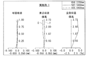
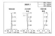
- FIG. 3 is an aberration diagram showing various aberrations in Numerical Example 1 in which specific numerical values are applied to the imaging lens illustrated in FIG. 1. It is a lens sectional view showing the 2nd example of composition of an imaging lens.
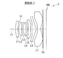
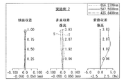
- FIG. 4 is an aberration diagram showing various aberrations in Numerical Example 2 in which specific numerical values are applied to the imaging lens illustrated in FIG. 3. It is a lens sectional view showing the 3rd example of composition of an imaging lens.
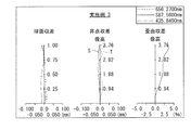
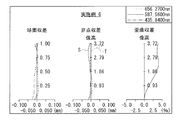
- FIG. 6 is an aberration diagram showing various aberrations in Numerical Example 3 in which specific numerical values are applied to the imaging lens illustrated in FIG. 5. It is lens sectional drawing which shows the 4th structural example of an imaging lens.
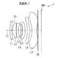
- FIG. 10 is an aberration diagram illustrating various aberrations in Numerical Example 4 in which specific numerical values are applied to the imaging lens illustrated in FIG. 7. It is a lens sectional view showing the 5th example of composition of an imaging lens.
- FIG. 10 is an aberration diagram illustrating various aberrations in Numerical Example 5 in which specific numerical values are applied to the imaging lens illustrated in FIG. 9. It is a lens sectional view showing the 6th example of composition of an imaging lens.
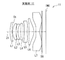
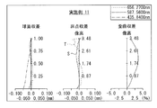
- FIG. 12 is an aberration diagram illustrating various aberrations in Numerical Example 6 in which specific numerical values are applied to the imaging lens illustrated in FIG. 11. It is a lens sectional view showing the 7th example of composition of an imaging lens.
- FIG. 10 is an aberration diagram illustrating various aberrations in Numerical Example 4 in which specific numerical values are applied to the imaging lens illustrated in FIG. 7. It is a lens sectional view showing the 5th example of composition of an imaging lens.
- FIG. 10 is an aberration diagram illustrating various aberrations in Numerical Example 5 in which
- FIG. 14 is an aberration diagram illustrating various aberrations in Numerical Example 7 in which specific numerical values are applied to the imaging lens illustrated in FIG. 13. It is lens sectional drawing which shows the 8th structural example of an imaging lens.
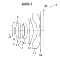
- FIG. 16 is an aberration diagram illustrating various aberrations in Numerical Example 8 in which specific numerical values are applied to the imaging lens illustrated in FIG. 15. It is lens sectional drawing which shows the 9th structural example of an imaging lens.
- FIG. 18 is an aberration diagram illustrating various aberrations in Numerical Example 9 in which specific numerical values are applied to the imaging lens illustrated in FIG. 17. It is lens sectional drawing which shows the 10th structural example of an imaging lens.
- FIG. 16 is an aberration diagram illustrating various aberrations in Numerical Example 8 in which specific numerical values are applied to the imaging lens illustrated in FIG. 15. It is lens sectional drawing which shows the 9th structural example of an imaging lens.
- FIG. 18 is an aberration diagram illustrating various aberrations in Numerical Example 9 in which specific numerical values are applied to the imaging
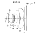
- FIG. 20 is an aberration diagram illustrating various aberrations in Numerical Example 10 in which specific numerical values are applied to the imaging lens illustrated in FIG. 19. It is a lens sectional view showing the 11th example of composition of an imaging lens.
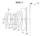
- FIG. 22 is an aberration diagram illustrating various aberrations in Numerical Example 11 in which specific numerical values are applied to the imaging lens illustrated in FIG. 21. It is a lens sectional view showing the 12th example of composition of an imaging lens.
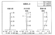
- FIG. 24 is an aberration diagram illustrating various aberrations in Numerical Example 12 in which specific numerical values are applied to the imaging lens illustrated in FIG. 23. It is a lens sectional view showing the 13th example of composition of an imaging lens.
- FIG. 22 is an aberration diagram illustrating various aberrations in Numerical Example 11 in which specific numerical values are applied to the imaging lens illustrated in FIG. 21.
- FIG. 24 is an aberration diagram illustrating various aberrations in Numerical Example 12 in which specific numerical values are applied to the imaging lens illustrated in FIG. 23. It is
- FIG. 26 is an aberration diagram illustrating various aberrations in Numerical Example 13 in which specific numerical values are applied to the imaging lens illustrated in FIG. 25. It is a lens sectional view showing the 14th example of composition of an imaging lens.
- FIG. 28 is an aberration diagram illustrating various aberrations in Numerical Example 14 in which specific numerical values are applied to the imaging lens illustrated in FIG. 27. It is a lens sectional view showing the 15th example of composition of an imaging lens.
- FIG. 30 is an aberration diagram illustrating various aberrations in Numerical Example 15 in which specific numerical values are applied to the imaging lens illustrated in FIG. 29. It is a lens sectional view showing the 16th example of composition of an imaging lens.
- FIG. 28 is an aberration diagram illustrating various aberrations in Numerical Example 14 in which specific numerical values are applied to the imaging lens illustrated in FIG. 27.
- FIG. 30 is an aberration diagram illustrating various aberrations in Numerical Example 15 in which specific numerical values are applied to the imaging lens illustrated in FIG. 29. It
- FIG. 32 is an aberration diagram showing various aberrations in Numerical Example 16 in which specific numerical values are applied to the imaging lens illustrated in FIG. 31. It is a lens sectional view showing the 17th example of composition of an imaging lens.
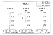
- FIG. 34 is an aberration diagram showing various aberrations in Numerical Example 17 in which specific numerical values are applied to the imaging lens illustrated in FIG. 33. It is a lens sectional view showing the 18th example of composition of an imaging lens.
- FIG. 36 is an aberration diagram showing various aberrations in Numerical Example 18 in which specific numerical values are applied to the imaging lens illustrated in FIG. 35. It is a lens sectional view showing the 19th example of composition of an imaging lens.
- FIG. 34 is an aberration diagram showing various aberrations in Numerical Example 17 in which specific numerical values are applied to the imaging lens illustrated in FIG. 33.
- FIG. 36 is an aberration diagram showing various aberrations in Numerical Example 18 in which specific numerical values are applied to the imaging lens illustrated in FIG. 35.
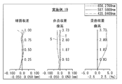
- FIG. 38 is an aberration diagram showing various aberrations in Numerical Example 19 in which specific numerical values are applied to the imaging lens illustrated in FIG. 37. It is sectional drawing which shows the generation
- a first lens, a positive second lens, a third lens, a fourth lens, a fifth lens, and a sixth lens are sequentially arranged from the object side to the image plane side.
- a bright lens composed of a lens and a seventh lens has been proposed.
- a configured lens having a brightness of about F1.6 has been proposed.
- the imaging lens disclosed in Patent Document 1 has been proposed to have a large aperture and a bright lens, the shape of the lens surface on the object side of the first lens is concave on the object side, or the first lens is biconvex, thereby shortening the overall length.
- the ratio of the maximum image height to the total length is 1.7 or more.
- the seven-lens imaging lens described in Patent Document 2 has a bright F1.6 lens, but the ratio of the maximum image height to the total length is 1.8 or more.
- the imaging lenses described in Patent Document 1 and Patent Document 2 have room for improvement in reducing the optical length while maintaining performance with a large aperture. Further, when the imaging lens is reduced in height, the distance between the optical surface and the imaging surface is shortened, so that reflected light easily enters the imaging surface from the optical surface, and the tendency for ghosts and flares to occur becomes significant. In particular, when the F-number of the imaging lens is reduced in response to the demand for a large aperture of the lens in relation to high performance, the effective diameter of the lens increases, and the diameter of the light shielding member increases accordingly, The risk of increased ghosts and flares increases.
- an imaging lens and an imaging apparatus that can effectively correct various aberrations by efficiently suppressing ghosts and flares while having a small size and a large aperture.
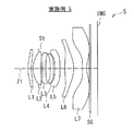
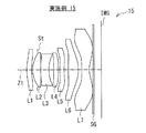
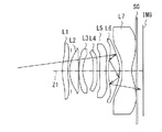
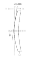
- FIG. 1 illustrates a first configuration example of an imaging lens according to an embodiment of the present disclosure.
- FIG. 3 shows a second configuration example of the imaging lens.
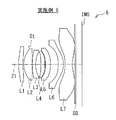
- FIG. 5 shows a third configuration example of the imaging lens.
- FIG. 7 shows a fourth configuration example of the imaging lens.
- FIG. 9 shows a fifth configuration example of the imaging lens.
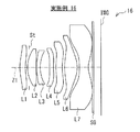
- FIG. 11 shows a sixth configuration example of the imaging lens.
- FIG. 13 shows a seventh configuration example of the imaging lens.
- FIG. 15 shows an eighth configuration example of the imaging lens.
- FIG. 17 shows a ninth configuration example of the imaging lens.
- FIG. 19 shows a tenth configuration example of the imaging lens.
- FIG. 21 shows an eleventh configuration example of the imaging lens.
- FIG. 23 shows a twelfth configuration example of the imaging lens.
- FIG. 1 illustrates a first configuration example of an imaging lens according to an embodiment of the present disclosure.
- FIG. 3 shows a second configuration example of the imaging lens.
- FIG. 5 shows a third
- FIG. 25 shows a thirteenth configuration example of the imaging lens.
- FIG. 27 shows a fourteenth configuration example of the imaging lens.
- FIG. 29 shows a fifteenth configuration example of the imaging lens.
- FIG. 31 shows a sixteenth configuration example of the imaging lens.
- FIG. 33 shows a seventeenth configuration example of the imaging lens.
- FIG. 35 shows an eighteenth configuration example of the imaging lens.
- FIG. 37 shows a nineteenth configuration example of the imaging lens. Numerical examples in which specific numerical values are applied to these configuration examples will be described later.
- symbol IMG indicates an image plane
- Z1 indicates an optical axis.
- St indicates an aperture stop.
- An imaging element 101 such as a CCD or a CMOS may be disposed in the vicinity of the image plane IMG.
- optical members such as a sealing glass SG for protecting the imaging element and various optical filters may be arranged.
- the configuration of the imaging lens according to the present embodiment will be described in association with the configuration example illustrated in FIG. 1 and the like as appropriate, but the technology according to the present disclosure is not limited to the illustrated configuration example.
- the imaging lens according to the present embodiment includes a first lens L1, a second lens L2, a third lens L3, and a fourth lens L4 in order from the object side to the image plane side along the optical axis Z1.
- the fifth lens L5, the sixth lens L6, and the seventh lens L7 are substantially composed of seven lenses.
- the first lens L1 has a meniscus shape in which the shape in the vicinity of the optical axis is convex toward the object side.
- the first lens L1 desirably has a positive or negative refractive power in the vicinity of the optical axis.
- the second lens L2 has a convex surface facing the object side in the vicinity of the optical axis.
- the second lens L2 desirably has a positive refractive power in the vicinity of the optical axis.
- the third lens L3 has a negative refractive power in the vicinity of the optical axis.
- the fourth lens L4 has a positive or negative refractive power in the vicinity of the optical axis.
- the fifth lens L5 has a positive or negative refractive power in the vicinity of the optical axis.
- the sixth lens L6 has a positive refractive power in the vicinity of the optical axis.
- the seventh lens L7 has a negative refractive power in the vicinity of the optical axis.
- the seventh lens L7 has an aspherical shape having an inflection point in which the concave-convex shape changes midway as the lens surface on the image plane side moves from the center to the periphery, and other than the intersection with the optical axis Z1. It is desirable to have at least one inflection point. More specifically, the image surface side lens surface of the seventh lens L7 is preferably an aspherical surface having a concave shape in the vicinity of the optical axis and a peripheral portion having a convex shape.
- the imaging lens according to the present embodiment further satisfies a predetermined conditional expression described later.
- the imaging lens according to the present embodiment has a seven-lens configuration as a whole, and the configuration of each lens is optimized, so that various aberrations can be corrected satisfactorily even though it is small and has a large aperture. In addition, image quality deterioration due to unnecessary light such as ghost and flare can be reduced.
- the aspherical surface in which the lens surface closest to the image plane has a concave shape in the vicinity of the optical axis and the peripheral portion has a convex shape.
- the imaging lens according to the present embodiment desirably satisfies the following conditional expression (1). -0.5 ⁇ f / f1 ⁇ 0.23 (1)
- f Focal length of the entire lens system
- f1 A focal length of the first lens L1.
- the conditional expression (1) defines the ratio between the focal length of the first lens L1 and the focal length of the entire lens system.
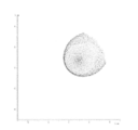
- FIG. 39 shows an example of a generation path of baying and glare generated by inter-surface reflection of the first lens L1.
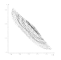
- FIG. 40 shows the shape of baying and glare generated by the inter-surface reflection of the first lens L1 in the imaging lens 1 according to the first configuration example of FIG. The relative intensity of the baling glare at this time is 1.
- the positive refractive power of the first lens L1 becomes too strong.
- the object-side lens surface of the first lens L1. A part of the light beam incident on the surface is reflected by the lens surface on the image plane side of the first lens L1, and further reflected by the lens surface on the object side, and then forms an image near the image plane.
- strong baying glare having a relative intensity of about 3.9 collected on the arc is generated.
- a part of the luminous flux near the principal ray out of the luminous flux incident on the first lens L1 is the lens surface on the image plane side of the first lens L1.
- the light is reflected from the surface, and further reflected from the lens surface on the object side, and then the image is formed near the image plane.
- strong bailing glare having a condensed relative intensity of about 24.4 occurs.
- conditional expression (1) In order to better realize the effect of the conditional expression (1), it is more desirable to set the numerical range of the conditional expression (1) as the following conditional expression (1) ′. -0.20 ⁇ f / f1 ⁇ 0.20 (1) '
- conditional expression (1) In order to realize the effect of the conditional expression (1) more satisfactorily, it is more desirable to set the numerical range of the conditional expression (1) as the following conditional expression (1) ′′. -0.074 ⁇ f / f1 ⁇ 0.092 (1) ''
- conditional expression (1) '' the object-side lens surface and the image-side lens surface of the first lens L1, and the object-side lens of the second lens L2 Regardless of whether the surface is concave or convex in the vicinity of the optical axis, baying and glare can be reduced and good resolution performance can be ensured despite the large aperture.
- the imaging lens according to the present embodiment further satisfies the following conditional expressions (2) and (3).
- ⁇ max (L1R1) Maximum value of the surface angle ⁇ (L1R1) of the lens surface on the object side of the first lens L1 within the effective diameter R (L3R2): The radius of curvature of the lens surface on the image plane side of the third lens L3 .
- FIG. 49 shows an example of the surface angle ⁇ (L1R1) of the lens surface on the object side of the first lens L1.
- the surface angle ⁇ (L1R1) is positive when the lens surface is inclined toward the image plane side and negative when the lens surface is inclined toward the object side.
- the unit is “degree”. The same applies to the surface angles of other lens surfaces in other conditional expressions described later.
- conditional expression (2) defines the maximum inclination angle of the lens surface on the object side of the first lens L1.
- Conditional expression (3) defines the ratio between the curvature of the lens surface on the image plane side of the third lens L3 and the focal length of the entire lens system.
- FIG. 43 shows a baying glare generated by total reflection on the image surface side lens surface of the third lens L3 and surface reflection on the object side lens surface of the first lens L1 and then reaching the image surface IMG. An example of the generation path of is shown.
- conditional expression (2) In order to better realize the effect of the conditional expression (2), it is more desirable to set the numerical range of the conditional expression (2) as the following conditional expression (2) ′. 5 ⁇ max (L1R1) ⁇ 18 (2) ′
- the imaging lens according to the present embodiment further satisfies the following conditional expressions (4) and (5).
- ⁇ max (L6R1) The maximum value of the surface angle ⁇ (L6R1) of the lens surface on the object side of the sixth lens L6 within 30% of the effective diameter (positive when the lens surface is inclined toward the image surface side, the unit being "Every time")
- ⁇ min (L6R1) the minimum value of the surface angle ⁇ (L6R1) of the lens surface on the object side of the sixth lens L6 within 30% of the effective diameter (positive when the lens surface is inclined toward the image surface side, the unit being "Every time”
- ⁇ max (L6R2) the maximum value of the surface angle ⁇ (L6R2) of the lens surface on the image surface side of the sixth lens L6 within the diameter of 70% of
- the conditional expression (4) defines the range of the maximum value of the surface angle ⁇ (L6R1) of the object-side lens surface of the sixth lens L6 within 30% of the effective diameter.
- FIG. 45 shows an example of a generation path of baying and glare generated by inter-surface reflection of the sixth lens L6.
- the conditional expression (5) defines the range of the maximum value of the surface angle ⁇ (L6R2) of the lens surface on the image surface side of the sixth lens L6 within the diameter of 70% of the effective diameter. Satisfactory conditional expression (5) can ensure good performance. If ⁇ max (L6R2) exceeds the upper limit value of conditional expression (5), the convex power of the lens surface on the image plane side of the sixth lens L6 is insufficient and the correction power for off-axis coma is insufficient, resulting in poor image quality. It will cause deterioration. When ⁇ max (L6R2) falls below the lower limit value of the conditional expression (5), for example, as shown in FIG.
- a part of the off-axis light beam reflected on the lens surface on the image plane side of the sixth lens L6 is the first.
- the sixth lens L6 is totally reflected without being emitted from the object-side lens surface, and is repeatedly totally reflected in the sixth lens L6, and then emitted from the lens surface on the image surface side of the sixth lens L6 to the image surface IMG. To reach.
- strong concentrated baying glare is generated as shown in FIG. 46, for example.
- conditional expression (4) it is more desirable to set the numerical range of the conditional expression (4) as the following conditional expression (4) ′. ⁇ 10 ⁇ min (L6R1) ⁇ max (L6R1) ⁇ 8 (4) ′
- conditional expression (4) In order to realize the effect of the conditional expression (4) more satisfactorily, it is more desirable to set the numerical range of the conditional expression (4) as the following conditional expression (4) ′′. ⁇ 6 ⁇ max (L6R1) ⁇ 7 (4) ′′
- conditional expression (5) it is more desirable to set the numerical range of the conditional expression (5) as the following conditional expression (5) ′. ⁇ 22 ⁇ min (L6R2) ⁇ max (L6R2) ⁇ 8 (5) ′
- the imaging lens according to the present embodiment further satisfies the following conditional expression (6).
- ⁇ max (L3R2) the maximum value of the surface angle ⁇ (L3R2) of the lens surface on the image surface side of the third lens L3 within the effective diameter (positive when the lens surface is inclined toward the image surface side, the unit is “degree”)
- ⁇ max (L3R2) the maximum value of the surface angle ⁇ (L3R2) of the lens surface on the image surface side of the third lens L3 within the effective diameter (positive when the lens surface is inclined toward the image surface side, the unit is “degree”)
- the conditional expression (6) defines the range of the maximum value of the surface angle ⁇ (L3R2) of the lens surface on the image surface side of the third lens L3 within the effective diameter. Satisfying conditional expression (6) can ensure good performance.
- ⁇ max (L3R2) falls below the lower limit value of conditional expression (6), the negative refractive power of the third lens L3 becomes weak, and spherical aberration and coma generated in the first lens L1 or the second lens L2 are corrected well. It becomes difficult. If ⁇ max (L3R2) exceeds the upper limit value of conditional expression (6), the third lens L3 has excessive negative power, making it difficult to correct spherical aberration and coma aberration, and the surface angle is too large. This increases the manufacturing difficulty.
- conditional expression (6) In order to better realize the effect of the conditional expression (6), it is more desirable to set the numerical range of the conditional expression (6) as the following conditional expression (6) ′. 15 ⁇ (L3R2) ⁇ 38 (6) ′
- the imaging lens according to the present embodiment further satisfies the following conditional expression (7).
- f Focal length of the entire lens system
- f12 The combined focal length of the first lens L1 and the second lens L2.
- conditional expression (7) defines the ratio between the combined focal length of the first lens L1 and the second lens L2 and the focal length of the entire lens system. Satisfying conditional expression (7) can ensure good performance. If f12 / f falls below the lower limit value of conditional expression (7), the combined power of the first lens L1 and the second lens L2 becomes too strong, making it difficult to correct spherical aberration, coma aberration, and astigmatism. . If f12 / f exceeds the upper limit value of conditional expression (7), the combined power of the first lens L1 and the second lens L2 becomes too weak, making it difficult to shorten the optical total length.
- conditional expression (7) it is more desirable to set the numerical range of the conditional expression (7) as the following conditional expression (7) ′. 0.5 ⁇ f12 / f ⁇ 1.5 (7) ′
- the imaging lens according to the present embodiment further satisfies the following conditional expression (8). ⁇ 5 ⁇ f3 / f ⁇ 0.5 (8)
- f Focal length of the entire lens system
- f3 The focal length of the third lens L3.
- conditional expression (8) defines the ratio between the focal length of the third lens L3 and the focal length of the entire lens system. Satisfying conditional expression (8) can ensure good performance.
- f3 / f falls below the lower limit value of conditional expression (8), the negative refractive power of the third lens L3 becomes weak, and it is difficult to satisfactorily correct the longitudinal chromatic aberration generated in the positive second lens L2.
- f3 / f exceeds the upper limit value of conditional expression (8), the negative refractive power of the third lens L3 becomes too strong, making it difficult to shorten the optical total length.
- conditional expression (8) it is more desirable to set the numerical range of the conditional expression (8) as the following conditional expression (8) ′. -3.5 ⁇ f3 / f ⁇ -1.0 (8) '
- the imaging lens according to the present embodiment further satisfies the following conditional expression (9). 0.023 ⁇ T (L3) / f ⁇ 0.15 (9)
- f Focal length of the entire lens system
- T (L3) The center thickness of the third lens L3.
- the conditional expression (9) defines the ratio between the center thickness of the third lens L3 and the focal length of the entire lens system.
- the third lens L3 has a concave meniscus shape, although the coma aberration can be easily corrected by reducing the center thickness, the lens moldability becomes difficult.
- T (L3) / f within the range of conditional expression (9), the coma aberration is kept good, and molding becomes easy.
- conditional expression (9) it is more desirable to set the numerical range of the conditional expression (9) as the following conditional expression (9) ′. 0.045 ⁇ T (L3) / f ⁇ 0.1 (9) ′
- the imaging lens according to the present embodiment further satisfies the following conditional expression (10).
- the imaging lens according to the present embodiment further satisfies the following conditional expressions (11) and (12).
- ⁇ d (L3) Abbe number of the third lens L3 with respect to the d-line
- ⁇ d (L5) Abbe number of the fifth lens L5 with respect to the d-line.
- conditional expression (10) defines the Abbe number for the d-line of the glass material of the first lens L1.
- the conditional expressions (11) and (12) define the Abbe numbers with respect to the d-line of the glass material of the third lens L3 and the fifth lens L5, respectively.
- the imaging lens according to the present embodiment further satisfies the following conditional expressions (13), (14), and (15).
- ⁇ d (L7) Abbe number of the seventh lens L7 with respect to the d line.
- Conditional expressions (13), (14), and (15) respectively define the Abbe numbers for the d-line of the glass material of the fourth lens L4, the sixth lens L6, and the seventh lens L7.
- conditional expressions (13), (14), and (15) it is possible to ensure good performance with a low profile.
- the Abbe numbers of the sixth lens L6 and the seventh lens L7 exceed the lower limit values of the conditional expressions (13), (14), and (15), the effect of correcting chromatic aberration can be enhanced.
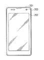
- This configuration example is an example of a mobile terminal device (for example, a mobile information terminal or a mobile phone terminal) provided with an imaging device.
- This portable terminal device includes a substantially rectangular casing 201.
- a display unit 202 and a front camera unit 203 are provided on the front side of the housing 201 (FIG. 47).
- a main camera unit 204 and a camera flash 205 are provided on the back side of the housing 201 (FIG. 48).
- the display unit 202 is a touch panel that enables various operations, for example, by detecting a contact state with the surface. Accordingly, the display unit 202 has a display function for displaying various types of information and an input function for enabling various input operations by the user.
- the display unit 202 displays various data such as an operation state and an image captured by the front camera unit 203 or the main camera unit 204.
- the imaging lens according to the present embodiment can be applied as a camera module lens of an imaging device (front camera unit 203 or main camera unit 204) in a portable terminal device as shown in FIGS. 47 and 48, for example.
- a CCD that outputs an imaging signal (image signal) corresponding to an optical image formed by the imaging lens near the image plane IMG of the imaging lens
- An image sensor 101 such as a CMOS is disposed.
- an optical member such as a sealing glass SG for protecting the image sensor and various optical filters may be disposed between the seventh lens L7 and the image plane IMG.
- optical members such as the seal glass SG and various optical filters may be disposed at any position as long as they are between the seventh lens L7 and the image plane IMG.
- the imaging lens according to the present embodiment is not limited to the above-described portable terminal device, but can also be applied as an imaging lens for other electronic devices such as a digital still camera and a digital video camera.
- the present invention can be applied to general small-sized imaging devices using a solid-state imaging device such as a CCD or CMOS, for example, an optical sensor, a portable module camera, and a WEB camera. It can also be applied to surveillance cameras and the like.
- Si indicates the number of the i-th surface with a sign so as to increase sequentially from the most object side.
- Ri indicates the value (mm) of the paraxial radius of curvature of the i-th surface.
- Di indicates the value (mm) of the distance on the optical axis between the i-th surface and the i + 1-th surface.
- Ndi indicates the value of the refractive index at the d-line (wavelength 587.6 nm) of the material of the optical element having the i-th surface.
- ⁇ di indicates the value of the Abbe number in the d-line of the material of the optical element having the i-th surface.
- the part where the value of “Ri” is “ ⁇ ” indicates a plane or a virtual plane.
- “Li” indicates a surface attribute.
- the surface marked “OBJ” in “Li” indicates the object surface.
- L1R1 indicates the object-side lens surface of the first lens L1
- L1R2 indicates the image-side lens surface of the first lens L1.
- L2R1 indicates the object-side lens surface of the second lens L2
- “L2R2” indicates the image-side lens surface of the second lens L2. The same applies to other lens surfaces.
- the surface marked “ASP” in “Si” indicates an aspherical surface.
- the aspherical shape is defined by the following equation.
- E ⁇ i represents an exponential expression with a base of 10, that is, “10 ⁇ i ”.
- 0.12345E-05 represents “ 0.12345 ⁇ 10 ⁇ 5 ”.
- All of the imaging lenses 1 to 19 to which the following numerical examples are applied have a configuration satisfying the basic configuration of the lens described above. That is, all of the imaging lenses 1 to 19 are in order from the object side to the image plane side, the first lens L1, the second lens L2, the third lens L3, the fourth lens L4, and the fifth lens L5. And the sixth lens L6 and the seventh lens L7 are substantially composed of seven lenses.
- the first lens L1 has a meniscus shape in which the shape in the vicinity of the optical axis is convex toward the object side.
- the second lens L2 has a convex surface facing the object side in the vicinity of the optical axis.
- the seventh lens L7 has an aspherical shape in which the lens surface on the image side has an inflection point at which the uneven shape changes in the middle from the center to the periphery.
- the aperture stop St is disposed between the image surface side lens surface of the first lens L1 and the image surface side lens surface of the second lens L2.
- a seal glass SG is disposed between the seventh lens L7 and the image plane IMG.
- both surfaces of each of the first lens L1 to the seventh lens L7 are aspherical.
- [Table 2] and [Table 3] show values of coefficients representing the shape of the aspheric surfaces.
- the first lens L1 has a positive refractive power in the vicinity of the optical axis.
- the second lens L2 has a positive refractive power in the vicinity of the optical axis.
- the third lens L3 has a negative refractive power in the vicinity of the optical axis.
- the fourth lens L4 has a positive refractive power in the vicinity of the optical axis.
- the fifth lens L5 has a negative refractive power in the vicinity of the optical axis.
- the sixth lens L6 has a positive refractive power in the vicinity of the optical axis.
- the seventh lens L7 has a negative refractive power in the vicinity of the optical axis.
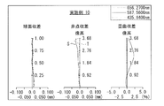
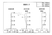
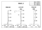
- FIG. 2 shows spherical aberration, astigmatism (field curvature), and distortion as various aberrations.
- Each of these aberration diagrams shows aberrations with the d-line (587.56 nm) as a reference wavelength.
- the spherical aberration diagram also shows aberrations with respect to g-line (435.84 nm) and C-line (656.27 nm).
- a solid line (S) indicates a value on a sagittal image plane
- T indicates a value on a tangential image plane.
- the imaging lens 1 according to Numerical Example 1 has a good optical performance with various aberrations corrected satisfactorily even though it is small.
- both surfaces of each of the first lens L1 to the seventh lens L7 are aspherical.
- [Table 5] and [Table 6] show coefficient values representing the shape of the aspheric surfaces.
- the first lens L1 has a positive refractive power in the vicinity of the optical axis.
- the second lens L2 has a positive refractive power in the vicinity of the optical axis.
- the third lens L3 has a negative refractive power in the vicinity of the optical axis.
- the fourth lens L4 has a positive refractive power in the vicinity of the optical axis.
- the fifth lens L5 has a negative refractive power in the vicinity of the optical axis.
- the sixth lens L6 has a positive refractive power in the vicinity of the optical axis.
- the seventh lens L7 has a negative refractive power in the vicinity of the optical axis.
- both surfaces of each of the first lens L1 to the seventh lens L7 are aspherical.
- [Table 8] and [Table 9] show coefficient values representing the shape of the aspheric surfaces.
- the first lens L1 has a negative refractive power in the vicinity of the optical axis.
- the second lens L2 has a positive refractive power in the vicinity of the optical axis.
- the third lens L3 has a negative refractive power in the vicinity of the optical axis.
- the fourth lens L4 has a negative refractive power in the vicinity of the optical axis.
- the fifth lens L5 has a positive refractive power in the vicinity of the optical axis.
- the sixth lens L6 has a positive refractive power in the vicinity of the optical axis.
- the seventh lens L7 has a negative refractive power in the vicinity of the optical axis.
- both surfaces of each of the first lens L1 to the seventh lens L7 are aspherical.
- [Table 11] and [Table 12] show values of coefficients representing the shape of the aspheric surfaces.
- the first lens L1 has a positive refractive power in the vicinity of the optical axis.
- the second lens L2 has a positive refractive power in the vicinity of the optical axis.
- the third lens L3 has a negative refractive power in the vicinity of the optical axis.
- the fourth lens L4 has a positive refractive power in the vicinity of the optical axis.
- the fifth lens L5 has a negative refractive power in the vicinity of the optical axis.
- the sixth lens L6 has a positive refractive power in the vicinity of the optical axis.
- the seventh lens L7 has a negative refractive power in the vicinity of the optical axis.
- Table 13 shows basic lens data of Numerical Example 5 in which specific numerical values are applied to the imaging lens 5 shown in FIG.
- both surfaces of each of the first lens L1 to the seventh lens L7 are aspherical.
- [Table 14] and [Table 15] show values of coefficients representing the shape of the aspheric surfaces.
- the first lens L1 has a positive refractive power in the vicinity of the optical axis.
- the second lens L2 has a positive refractive power in the vicinity of the optical axis.
- the third lens L3 has a negative refractive power in the vicinity of the optical axis.
- the fourth lens L4 has a negative refractive power in the vicinity of the optical axis.
- the fifth lens L5 has a negative refractive power in the vicinity of the optical axis.
- the sixth lens L6 has a positive refractive power in the vicinity of the optical axis.
- the seventh lens L7 has a negative refractive power in the vicinity of the optical axis.
- both surfaces of each of the first lens L1 to the seventh lens L7 are aspherical.
- [Table 17] and [Table 18] show values of coefficients representing the shape of the aspheric surfaces.
- the first lens L1 has a positive refractive power in the vicinity of the optical axis.
- the second lens L2 has a positive refractive power in the vicinity of the optical axis.
- the third lens L3 has a negative refractive power in the vicinity of the optical axis.
- the fourth lens L4 has a positive refractive power in the vicinity of the optical axis.
- the fifth lens L5 has a positive refractive power in the vicinity of the optical axis.
- the sixth lens L6 has a positive refractive power in the vicinity of the optical axis.
- the seventh lens L7 has a negative refractive power in the vicinity of the optical axis.
- Table 19 shows basic lens data of Numerical Example 7 in which specific numerical values are applied to the imaging lens 7 shown in FIG.
- both surfaces of each of the first lens L1 to the seventh lens L7 are aspherical.
- [Table 20] and [Table 21] show coefficient values representing the shape of the aspheric surfaces.
- the first lens L1 has a positive refractive power in the vicinity of the optical axis.
- the second lens L2 has a positive refractive power in the vicinity of the optical axis.
- the third lens L3 has a negative refractive power in the vicinity of the optical axis.
- the fourth lens L4 has a positive refractive power in the vicinity of the optical axis.
- the fifth lens L5 has a positive refractive power in the vicinity of the optical axis.
- the sixth lens L6 has a positive refractive power in the vicinity of the optical axis.
- the seventh lens L7 has a negative refractive power in the vicinity of the optical axis.
- both surfaces of each of the first lens L1 to the seventh lens L7 are aspherical.
- [Table 23] and [Table 24] show values of coefficients representing the shape of the aspheric surfaces.
- the first lens L1 has a positive refractive power in the vicinity of the optical axis.
- the second lens L2 has a positive refractive power in the vicinity of the optical axis.
- the third lens L3 has a negative refractive power in the vicinity of the optical axis.
- the fourth lens L4 has a negative refractive power in the vicinity of the optical axis.
- the fifth lens L5 has a negative refractive power in the vicinity of the optical axis.
- the sixth lens L6 has a positive refractive power in the vicinity of the optical axis.
- the seventh lens L7 has a negative refractive power in the vicinity of the optical axis.
- Table 25 shows basic lens data of Numerical Example 9 in which specific numerical values are applied to the imaging lens 9 shown in FIG.
- both surfaces of each of the first lens L1 to the seventh lens L7 are aspherical.
- [Table 26] and [Table 27] show coefficient values representing the shape of the aspheric surfaces.
- the first lens L1 has a positive refractive power in the vicinity of the optical axis.
- the second lens L2 has a positive refractive power in the vicinity of the optical axis.
- the third lens L3 has a negative refractive power in the vicinity of the optical axis.
- the fourth lens L4 has a positive refractive power in the vicinity of the optical axis.
- the fifth lens L5 has a negative refractive power in the vicinity of the optical axis.
- the sixth lens L6 has a positive refractive power in the vicinity of the optical axis.
- the seventh lens L7 has a negative refractive power in the vicinity of the optical axis.
- Table 28 shows basic lens data of Numerical Example 10 in which specific numerical values are applied to the imaging lens 10 shown in FIG.
- both surfaces of each of the first lens L1 to the seventh lens L7 are aspherical.
- [Table 29] and [Table 30] show coefficient values representing the shape of the aspheric surfaces.
- the first lens L1 has a positive refractive power in the vicinity of the optical axis.
- the second lens L2 has a positive refractive power in the vicinity of the optical axis.
- the third lens L3 has a negative refractive power in the vicinity of the optical axis.
- the fourth lens L4 has a negative refractive power in the vicinity of the optical axis.
- the fifth lens L5 has a negative refractive power in the vicinity of the optical axis.
- the sixth lens L6 has a positive refractive power in the vicinity of the optical axis.
- the seventh lens L7 has a negative refractive power in the vicinity of the optical axis.
- both surfaces of each of the first lens L1 to the seventh lens L7 are aspherical.
- [Table 32] and [Table 33] show coefficient values representing the shape of the aspheric surfaces.
- the first lens L1 has a positive refractive power in the vicinity of the optical axis.
- the second lens L2 has a positive refractive power in the vicinity of the optical axis.
- the third lens L3 has a negative refractive power in the vicinity of the optical axis.
- the fourth lens L4 has a positive refractive power in the vicinity of the optical axis.
- the fifth lens L5 has a negative refractive power in the vicinity of the optical axis.
- the sixth lens L6 has a positive refractive power in the vicinity of the optical axis.
- the seventh lens L7 has a negative refractive power in the vicinity of the optical axis.
- Table 34 shows basic lens data of Numerical Example 12 in which specific numerical values are applied to the imaging lens 12 shown in FIG.
- both surfaces of the first lens L1 to the seventh lens L7 are aspherical.
- [Table 35] and [Table 36] show coefficient values representing the shape of the aspheric surfaces.
- the first lens L1 has a positive refractive power in the vicinity of the optical axis.
- the second lens L2 has a positive refractive power in the vicinity of the optical axis.
- the third lens L3 has a negative refractive power in the vicinity of the optical axis.
- the fourth lens L4 has a positive refractive power in the vicinity of the optical axis.
- the fifth lens L5 has a positive refractive power in the vicinity of the optical axis.
- the sixth lens L6 has a positive refractive power in the vicinity of the optical axis.
- the seventh lens L7 has a negative refractive power in the vicinity of the optical axis.
- Table 37 shows basic lens data of Numerical Example 13 in which specific numerical values are applied to the imaging lens 13 shown in FIG.
- both surfaces of each of the first lens L1 to the seventh lens L7 are aspherical.
- [Table 38] and [Table 39] show coefficient values representing the shape of the aspheric surfaces.
- the first lens L1 has a positive refractive power in the vicinity of the optical axis.
- the second lens L2 has a positive refractive power in the vicinity of the optical axis.
- the third lens L3 has a negative refractive power in the vicinity of the optical axis.
- the fourth lens L4 has a positive refractive power in the vicinity of the optical axis.
- the fifth lens L5 has a negative refractive power in the vicinity of the optical axis.
- the sixth lens L6 has a positive refractive power in the vicinity of the optical axis.
- the seventh lens L7 has a negative refractive power in the vicinity of the optical axis.
- both surfaces of each of the first lens L1 to the seventh lens L7 are aspherical.
- [Table 41] and [Table 42] show values of coefficients representing the shape of the aspheric surfaces.
- the first lens L1 has a positive refractive power in the vicinity of the optical axis.
- the second lens L2 has a positive refractive power in the vicinity of the optical axis.
- the third lens L3 has a negative refractive power in the vicinity of the optical axis.
- the fourth lens L4 has a negative refractive power in the vicinity of the optical axis.
- the fifth lens L5 has a negative refractive power in the vicinity of the optical axis.
- the sixth lens L6 has a positive refractive power in the vicinity of the optical axis.
- the seventh lens L7 has a negative refractive power in the vicinity of the optical axis.
- both surfaces of each of the first lens L1 to the seventh lens L7 are aspherical.
- [Table 44] and [Table 45] show coefficient values representing the shape of the aspheric surfaces.
- the first lens L1 has a positive refractive power in the vicinity of the optical axis.
- the second lens L2 has a positive refractive power in the vicinity of the optical axis.
- the third lens L3 has a negative refractive power in the vicinity of the optical axis.
- the fourth lens L4 has a positive refractive power in the vicinity of the optical axis.
- the fifth lens L5 has a negative refractive power in the vicinity of the optical axis.
- the sixth lens L6 has a positive refractive power in the vicinity of the optical axis.
- the seventh lens L7 has a negative refractive power in the vicinity of the optical axis.
- Table 46 shows basic lens data of Numerical Example 16 in which specific numerical values are applied to the imaging lens 16 shown in FIG.
- both surfaces of each of the first lens L1 to the seventh lens L7 are aspherical.
- [Table 47] and [Table 48] show coefficient values representing the shape of the aspheric surfaces.
- the first lens L1 has a positive refractive power in the vicinity of the optical axis.
- the second lens L2 has a positive refractive power in the vicinity of the optical axis.
- the third lens L3 has a negative refractive power in the vicinity of the optical axis.
- the fourth lens L4 has a negative refractive power in the vicinity of the optical axis.
- the fifth lens L5 has a negative refractive power in the vicinity of the optical axis.
- the sixth lens L6 has a positive refractive power in the vicinity of the optical axis.
- the seventh lens L7 has a negative refractive power in the vicinity of the optical axis.
- Table 49 shows basic lens data of Numerical Example 17 in which specific numerical values are applied to the imaging lens 17 shown in FIG.
- both surfaces of each of the first lens L1 to the seventh lens L7 are aspherical.
- [Table 50] and [Table 51] show values of coefficients representing the shape of the aspheric surfaces.
- the first lens L1 has a positive refractive power in the vicinity of the optical axis.
- the second lens L2 has a positive refractive power in the vicinity of the optical axis.
- the third lens L3 has a negative refractive power in the vicinity of the optical axis.
- the fourth lens L4 has a positive refractive power in the vicinity of the optical axis.
- the fifth lens L5 has a negative refractive power in the vicinity of the optical axis.
- the sixth lens L6 has a positive refractive power in the vicinity of the optical axis.
- the seventh lens L7 has a negative refractive power in the vicinity of the optical axis.
- both surfaces of each of the first lens L1 to the seventh lens L7 are aspherical.
- [Table 53] and [Table 54] show coefficient values representing the shape of the aspheric surfaces.
- the first lens L1 has a positive refractive power in the vicinity of the optical axis.
- the second lens L2 has a positive refractive power in the vicinity of the optical axis.
- the third lens L3 has a negative refractive power in the vicinity of the optical axis.
- the fourth lens L4 has a positive refractive power in the vicinity of the optical axis.
- the fifth lens L5 has a negative refractive power in the vicinity of the optical axis.
- the sixth lens L6 has a positive refractive power in the vicinity of the optical axis.
- the seventh lens L7 has a negative refractive power in the vicinity of the optical axis.
- Table 55 shows basic lens data of Numerical Example 19 in which specific numerical values are applied to the imaging lens 19 shown in FIG.
- both surfaces of each of the first lens L1 to the seventh lens L7 are aspheric.
- [Table 56] and [Table 57] show coefficient values representing the shape of the aspheric surfaces.
- the first lens L1 has a positive refractive power in the vicinity of the optical axis.
- the second lens L2 has a positive refractive power in the vicinity of the optical axis.
- the third lens L3 has a negative refractive power in the vicinity of the optical axis.
- the fourth lens L4 has a negative refractive power in the vicinity of the optical axis.
- the fifth lens L5 has a negative refractive power in the vicinity of the optical axis.
- the sixth lens L6 has a positive refractive power in the vicinity of the optical axis.
- the seventh lens L7 has a negative refractive power in the vicinity of the optical axis.
- [Table 59] and [Table 60] show values relating to the above-described conditional expressions, which are summarized for each numerical example. Note that Example 18 is out of the range of conditional expression (2).
- the configuration including substantially seven lenses has been described.
- the configuration may further include a lens having substantially no refractive power.
- this technique can take the following composition.
- a first lens having a meniscus shape in which the shape near the optical axis has a convex surface facing the object side;
- a second lens having a positive refractive power with a convex surface facing the object side in the vicinity of the optical axis;
- a third lens having negative refractive power in the vicinity of the optical axis;
- a sixth lens having a positive refractive power in the vicinity of the optical axis;
- An imaging lens comprising: a seventh lens having a negative refractive power in the vicinity of the optical axis and having an aspherical shape with an inflection point on the lens surface on the image plane side.
- ⁇ max (L6R1) Maximum value of the surface angle of the object side lens surface of the sixth lens within 30% of the effective diameter (positive when the lens surface is tilted to the image surface side, the unit is “degree”)
- ⁇ min (L6R1) Minimum value of the surface angle of the object side lens surface of the sixth lens within 30% of the effective diameter (positive when the lens surface is tilted toward the image surface side, the unit is “degrees”)
- ⁇ min (L6R2) Minimum value of the surface angle of the sixth lens surface on the image surface side within 70% of the effective diameter (positive when the lens surface is inclined toward the image surface surface surface side
- f focal length of the entire lens system
- f3 the focal length of the third lens.
- f Focal length of the entire lens system T (L3): The center thickness of the third lens.
- a first lens In order from the object side to the image plane side, A first lens; A second lens having a positive refractive power in the vicinity of the optical axis; A third lens having negative refractive power in the vicinity of the optical axis; A fourth lens; A fifth lens; A sixth lens having a positive refractive power in the vicinity of the optical axis; An imaging lens that has a negative refractive power in the vicinity of the optical axis and has an aspherical shape with an inflection point on the lens surface on the image plane side, and satisfies the following conditional expression. -0.5 ⁇ f / f1 ⁇ 0.23 (1) However, f: focal length of the entire lens system f1: a focal length of the first lens.
- ⁇ max (L6R1) Maximum value of the surface angle of the object side lens surface of the sixth lens within 30% of the effective diameter (positive when the lens surface is tilted to the image surface side, the unit is “degree”)
- ⁇ min (L6R1) Minimum value of the surface angle of the object side lens surface of the sixth lens within 30% of the effective diameter (positive when the lens surface is tilted toward the image surface side, the unit is “degrees”)
- ⁇ min (L6R2) Minimum value of the surface angle of the sixth lens surface on the image surface side within 70% of the effective diameter (positive when the lens surface is inclined toward the image surface surface surface side
- f focal length of the entire lens system
- f3 the focal length of the third lens.
- f Focal length of the entire lens system T (L3): The center thickness of the third lens.
- the imaging lens is In order from the object side to the image plane side, A first lens having a meniscus shape in which the shape near the optical axis has a convex surface facing the object side; A second lens having a positive refractive power with a convex surface facing the object side in the vicinity of the optical axis; A third lens having negative refractive power in the vicinity of the optical axis; A fourth lens; A fifth lens; A sixth lens having a positive refractive power in the vicinity of the optical axis;
- An imaging apparatus comprising: a seventh lens having a negative refractive power in the vicinity of the optical axis and having an aspherical shape with an inflection point on the lens surface on the image plane side.
- the imaging lens is In order from the object side to the image plane side, A first lens; A second lens having a positive refractive power in the vicinity of the optical axis; A third lens having negative refractive power in the vicinity of the optical axis; A fourth lens; A fifth lens; A sixth lens having a positive refractive power in the vicinity of the optical axis;
- An imaging device that includes a seventh lens having a negative refractive power in the vicinity of the optical axis and an aspherical surface having an inflection point on the lens surface on the image plane side, and satisfies the following conditional expression.
- f focal length of the entire lens system
- f1 a focal length of the first lens.
Abstract
This imaging lens comprises, in sequence from the object side to the image surface side: a meniscus-shaped first lens in which the vicinity of the optical axis is shaped so as to be convex towards the object side; a second lens having a positive refractive power and shaped so as to be convex towards the object side in the vicinity of the optical axis; a third lens having a negative refractive power in the vicinity of the optical axis; a fourth lens; a fifth lens; a sixth lens having a positive refractive power in the vicinity of the optical axis; and a seventh lens having a negative refractive power in the vicinity of the optical axis, the image surface-side lens surface of the seventh lens having a non-spherical shape that has an inflection point.
Description
本開示は、CCD(Charge Coupled Device)やCMOS(Complementary Metal Oxide Semiconductor)等の撮像素子上に被写体の光学像を結像させる撮像レンズ、およびその撮像レンズを搭載して撮影を行うデジタルスチルカメラやカメラ付き携帯電話機および情報携帯端末等の撮像装置に関する。
The present disclosure relates to an imaging lens that forms an optical image of a subject on an imaging element such as a CCD (Charge Coupled Device) or a CMOS (Complementary Metal Oxide Semiconductor), and a digital still camera that performs shooting by mounting the imaging lens. The present invention relates to an imaging apparatus such as a mobile phone with a camera and an information mobile terminal.
デジタルスチルカメラはカードタイプなど年々薄型のものが作られ、撮像装置の小型化が求められている。また、携帯電話においても端末自体の薄型化や多機能を搭載するスペース確保のために撮像装置の小型化が求められている。それにより、撮像装置に搭載される撮像レンズへのさらなる小型化の要求が高まっている。
Digital still cameras are becoming thinner year by year, such as card types, and there is a demand for smaller imaging devices. Also in mobile phones, downsizing of the imaging device is required in order to reduce the thickness of the terminal itself and to secure a space for mounting multiple functions. As a result, there is an increasing demand for further downsizing the imaging lens mounted on the imaging device.
また、CCDやCMOSといった撮像素子の小型化と同時に、撮像素子の画素ピッチの微細化による高画素数化が進み、それに伴い、これら撮像装置に使用される撮像レンズにも高い性能が求められてきている。
In addition to the miniaturization of image sensors such as CCDs and CMOSs, the number of pixels has been increased by making the pixel pitch of the image sensor finer, and accordingly, the imaging lenses used in these imaging devices have been required to have high performance. ing.
近年、高画素化の進んだ撮像素子に対応するために、撮像レンズとしては、全長の短縮化を図りつつ中心画角から周辺画角まで高い結像性能を有するレンズ系の開発が望まれている。さらには、ゴーストやフレアによる画質劣化の低減が望まれている。
In recent years, in order to cope with imaging elements with an increased number of pixels, it is desirable to develop a lens system that has high imaging performance from the central field angle to the peripheral field angle while shortening the overall length. Yes. Furthermore, reduction of image quality degradation due to ghosts and flares is desired.
小型でありながらも諸収差を良好に補正し、かつ不要光による画質劣化を低減することができるようにした撮像レンズ、およびそのような撮像レンズを搭載した撮像装置を提供することが望ましい。
It is desirable to provide an imaging lens capable of correcting various aberrations satisfactorily and reducing image quality deterioration due to unnecessary light, and an imaging apparatus equipped with such an imaging lens, although it is small.
本開示の一実施の形態に係る第1の撮像レンズは、物体側から像面側に向かって順に、光軸近傍の形状が物体側に凸面を向けたメニスカス形状の第1レンズと、光軸近傍において物体側に凸面を向けた正の屈折力を有する第2レンズと、光軸近傍において負の屈折力を有する第3レンズと、第4レンズと、第5レンズと、光軸近傍において正の屈折力を有する第6レンズと、光軸近傍において負の屈折力を有し、像面側のレンズ面が変曲点を有する非球面形状とされた第7レンズとから構成されているものである。
A first imaging lens according to an embodiment of the present disclosure includes, in order from the object side to the image plane side, a meniscus-shaped first lens in which the shape in the vicinity of the optical axis has a convex surface facing the object side, and the optical axis A second lens having a positive refractive power with a convex surface facing the object side in the vicinity, a third lens having a negative refractive power in the vicinity of the optical axis, a fourth lens, a fifth lens, and a positive lens in the vicinity of the optical axis. And a seventh lens having a negative refractive power in the vicinity of the optical axis and an aspherical surface having an inflection point on the image side lens surface. It is.
本開示の一実施の形態に係る第1の撮像装置は、撮像レンズと、撮像レンズによって形成された光学像に応じた撮像信号を出力する撮像素子とを含み、撮像レンズを、上記本開示の一実施の形態に係る第1の撮像レンズによって構成したものである。
A first imaging device according to an embodiment of the present disclosure includes an imaging lens and an imaging element that outputs an imaging signal corresponding to an optical image formed by the imaging lens. This is constituted by a first imaging lens according to an embodiment.
本開示の一実施の形態に係る第2の撮像レンズは、物体側から像面側に向かって順に、第1レンズと、光軸近傍において正の屈折力を有する第2レンズと、光軸近傍において負の屈折力を有する第3レンズと、第4レンズと、第5レンズと、光軸近傍において正の屈折力を有する第6レンズと、光軸近傍において負の屈折力を有し、像面側のレンズ面が変曲点を有する非球面形状とされた第7レンズとから構成され、以下の条件式を満足するものである。
-0.5<f/f1<0.23 ……(1)
ただし、
f:レンズ全系の焦点距離
f1:第1レンズの焦点距離
とする。 A second imaging lens according to an embodiment of the present disclosure includes, in order from the object side to the image plane side, a first lens, a second lens having a positive refractive power in the vicinity of the optical axis, and the vicinity of the optical axis A third lens having a negative refractive power, a fourth lens, a fifth lens, a sixth lens having a positive refractive power in the vicinity of the optical axis, and a negative refractive power in the vicinity of the optical axis. The lens surface on the surface side is composed of an aspherical seventh lens having an inflection point, and satisfies the following conditional expression.
-0.5 <f / f1 <0.23 (1)
However,
f: Focal length of the entire lens system f1: The focal length of the first lens.
本開示の一実施の形態に係る第2の撮像装置は、撮像レンズと、撮像レンズによって形成された光学像に応じた撮像信号を出力する撮像素子とを含み、撮像レンズを、上記本開示の一実施の形態に係る第2の撮像レンズによって構成したものである。
A second imaging device according to an embodiment of the present disclosure includes an imaging lens and an imaging element that outputs an imaging signal corresponding to an optical image formed by the imaging lens. This is constituted by the second imaging lens according to one embodiment.
本開示の一実施の形態に係る第1および第2の撮像レンズ、または第1および第2の撮像装置では、全体として7枚のレンズ構成で、各レンズの構成の最適化が図られている。
In the first and second imaging lenses or the first and second imaging devices according to an embodiment of the present disclosure, the configuration of each lens is optimized with a configuration of seven lenses as a whole. .
本開示の一実施の形態に係る第1および第2の撮像レンズ、または第1および第2の撮像装置によれば、全体として7枚のレンズ構成とし、各レンズの構成の最適化を図るようにしたので、小型でありながらも諸収差を良好に補正し、かつ不要光による画質劣化を低減することができる。
According to the first and second imaging lenses or the first and second imaging devices according to an embodiment of the present disclosure, the configuration of the seven lenses as a whole is optimized, and the configuration of each lens is optimized. Therefore, it is possible to correct various aberrations satisfactorily while reducing the size, and to reduce image quality deterioration due to unnecessary light.
なお、ここに記載された効果は必ずしも限定されるものではなく、本開示中に記載されたいずれかの効果であってもよい。
It should be noted that the effects described here are not necessarily limited, and may be any of the effects described in the present disclosure.
以下、本開示の実施の形態について図面を参照して詳細に説明する。なお、説明は以下の順序で行う。
0.比較例
1.レンズの基本構成
2.作用・効果
3.撮像装置への適用例
4.レンズの数値実施例
5.その他の実施の形態 Hereinafter, embodiments of the present disclosure will be described in detail with reference to the drawings. The description will be given in the following order.
0. Comparative Example 1. Basic configuration of lens Action andeffect 3. Application example to imaging device 4. Numerical example of lens Other embodiments
0.比較例
1.レンズの基本構成
2.作用・効果
3.撮像装置への適用例
4.レンズの数値実施例
5.その他の実施の形態 Hereinafter, embodiments of the present disclosure will be described in detail with reference to the drawings. The description will be given in the following order.
0. Comparative Example 1. Basic configuration of lens Action and
<0.比較例>
高細化された撮像素子に使用される撮像レンズは高い解像力が要求されるが、解像力はF値により限界があり、F値の明るいレンズの方が高解像力を得られるため、F2.0程度のF値では十分な性能が得られなくなってきた。そこで、高画素化、高細化、および小型化された撮像素子に適したF1.6程度の明るさの撮像レンズが求められるようになってきた。このような用途の撮像レンズとして、例えば特許文献1(特開2015―072404号公報)および特許文献2(特開2014―145961号公報)には、5枚あるいは6枚構成のレンズに比べて大口径比化および高性能化が可能である7枚構成の撮像レンズが提案されている。 <0. Comparative Example>
An imaging lens used for a high-definition imaging device is required to have a high resolving power, but the resolving power is limited by the F value, and a lens having a bright F value can obtain a high resolving power. With this F value, sufficient performance cannot be obtained. Accordingly, an imaging lens having a brightness of about F1.6 suitable for an imaging device with a high pixel size, a high resolution, and a small size has been demanded. For example, Patent Document 1 (Japanese Patent Laid-Open No. 2015-0742404) and Patent Document 2 (Japanese Patent Laid-Open No. 2014-145961) have large imaging lenses for such applications as compared with a lens having five or six lenses. A seven-lens imaging lens that can achieve a high aperture ratio and high performance has been proposed.
例えば特許文献1に記載の7枚構成の撮像レンズでは、物体側から像面側に向かって順に、第1レンズ、正の第2レンズ、第3レンズ、第4レンズ、第5レンズ、第6レンズ、および第7レンズから構成されている明るいレンズが提案されている。また、特許文献2に記載の7枚構成の撮像レンズでは、物体側から像面側に向かって順に、光軸近傍で物体側に凸面を向けた正の第1レンズ、光軸近傍で物体側と像面側とに凸面を向けた正の第2レンズ、光軸近傍で像面側に凹面を向けた負の第3レンズ、少なくとも1面が非球面の第4レンズ、光軸近傍で物体側に凹面を向けたメニスカス形状の第5レンズ、両面が非球面の第6レンズ、および光軸近傍で像面側に凹面を向けた負の屈折力を有する両面が非球面の第7レンズから構成されているF1.6程度の明るさのレンズが提案されている。
For example, in the seven-lens imaging lens described in Patent Document 1, a first lens, a positive second lens, a third lens, a fourth lens, a fifth lens, and a sixth lens are sequentially arranged from the object side to the image plane side. A bright lens composed of a lens and a seventh lens has been proposed. In addition, in the imaging lens having a seven-lens structure described in Patent Document 2, a positive first lens having a convex surface toward the object side in the vicinity of the optical axis and the object side in the vicinity of the optical axis in order from the object side to the image plane side. Positive second lens with convex surface facing the image surface side, negative third lens with concave surface facing the image surface near the optical axis, fourth lens with at least one aspheric surface, object near the optical axis A fifth lens having a meniscus shape with a concave surface facing the side, a sixth lens having both surfaces aspherical, and a seventh lens having a negative refractive power with the concave surface facing the image surface in the vicinity of the optical axis. A configured lens having a brightness of about F1.6 has been proposed.
近年、高画素化の進んだ撮像素子に対応するために、撮像レンズとしては、全長の短縮化を図りつつ中心画角から周辺画角まで高い結像性能を有するレンズ系の開発が望まれている。上記特許文献1の撮像レンズは大口径の明るいものが提案されているものの、第1レンズの物体側のレンズ面の形状が物体側に凹、もしくは第1レンズが両凸形状と、全長を短縮する上で不利な形状となっており、全長に対する最大像高の比は1.7以上である。また上記特許文献2に記載の7枚構成の撮像レンズは、F1.6の明るいものが提案されているものの、全長に対する最大像高の比は1.8以上である。上記特許文献1および特許文献2に記載の撮像レンズは、大口径で性能を維持しつつ光学長を短縮化する上で、改善の余地がある。また、撮像レンズが低背化すると、光学面と撮像面との距離が短くなるため、光学面から撮像面に反射光が入射しやすくなり、ゴーストやフレアが生じる傾向が顕著になる。特に、高性能化に関連してレンズの大口径化の要求に応じて撮像レンズのFナンバーを小さくすると、レンズの有効径が大きくなり、それに伴い遮光部材の径も大きくなることにより、さらに、上記のゴーストやフレアが増えるおそれが高まる。
In recent years, in order to cope with imaging elements with an increased number of pixels, it is desirable to develop a lens system that has high imaging performance from the central field angle to the peripheral field angle while shortening the overall length. Yes. Although the imaging lens disclosed in Patent Document 1 has been proposed to have a large aperture and a bright lens, the shape of the lens surface on the object side of the first lens is concave on the object side, or the first lens is biconvex, thereby shortening the overall length. The ratio of the maximum image height to the total length is 1.7 or more. The seven-lens imaging lens described in Patent Document 2 has a bright F1.6 lens, but the ratio of the maximum image height to the total length is 1.8 or more. The imaging lenses described in Patent Document 1 and Patent Document 2 have room for improvement in reducing the optical length while maintaining performance with a large aperture. Further, when the imaging lens is reduced in height, the distance between the optical surface and the imaging surface is shortened, so that reflected light easily enters the imaging surface from the optical surface, and the tendency for ghosts and flares to occur becomes significant. In particular, when the F-number of the imaging lens is reduced in response to the demand for a large aperture of the lens in relation to high performance, the effective diameter of the lens increases, and the diameter of the light shielding member increases accordingly, The risk of increased ghosts and flares increases.
そこで、小型かつ大口径でありながらも、ゴーストやフレアを効率的に抑制して、諸収差を良好に補正することのできる撮像レンズ、および撮像装置を提供することが望ましい。
Therefore, it is desirable to provide an imaging lens and an imaging apparatus that can effectively correct various aberrations by efficiently suppressing ghosts and flares while having a small size and a large aperture.
<1.レンズの基本構成>
図1は、本開示の一実施の形態に係る撮像レンズの第1の構成例を示している。図3は、撮像レンズの第2の構成例を示している。図5は、撮像レンズの第3の構成例を示している。図7は、撮像レンズの第4の構成例を示している。図9は、撮像レンズの第5の構成例を示している。図11は、撮像レンズの第6の構成例を示している。図13は、撮像レンズの第7の構成例を示している。図15は、撮像レンズの第8の構成例を示している。図17は、撮像レンズの第9の構成例を示している。図19は、撮像レンズの第10の構成例を示している。図21は、撮像レンズの第11の構成例を示している。図23は、撮像レンズの第12の構成例を示している。図25は、撮像レンズの第13の構成例を示している。図27は、撮像レンズの第14の構成例を示している。図29は、撮像レンズの第15の構成例を示している。図31は、撮像レンズの第16の構成例を示している。図33は、撮像レンズの第17の構成例を示している。図35は、撮像レンズの第18の構成例を示している。図37は、撮像レンズの第19の構成例を示している。これらの構成例に具体的な数値を適用した数値実施例は後述する。 <1. Basic lens configuration>
FIG. 1 illustrates a first configuration example of an imaging lens according to an embodiment of the present disclosure. FIG. 3 shows a second configuration example of the imaging lens. FIG. 5 shows a third configuration example of the imaging lens. FIG. 7 shows a fourth configuration example of the imaging lens. FIG. 9 shows a fifth configuration example of the imaging lens. FIG. 11 shows a sixth configuration example of the imaging lens. FIG. 13 shows a seventh configuration example of the imaging lens. FIG. 15 shows an eighth configuration example of the imaging lens. FIG. 17 shows a ninth configuration example of the imaging lens. FIG. 19 shows a tenth configuration example of the imaging lens. FIG. 21 shows an eleventh configuration example of the imaging lens. FIG. 23 shows a twelfth configuration example of the imaging lens. FIG. 25 shows a thirteenth configuration example of the imaging lens. FIG. 27 shows a fourteenth configuration example of the imaging lens. FIG. 29 shows a fifteenth configuration example of the imaging lens. FIG. 31 shows a sixteenth configuration example of the imaging lens. FIG. 33 shows a seventeenth configuration example of the imaging lens. FIG. 35 shows an eighteenth configuration example of the imaging lens. FIG. 37 shows a nineteenth configuration example of the imaging lens. Numerical examples in which specific numerical values are applied to these configuration examples will be described later.
図1等において、符号IMGは像面、Z1は光軸を示す。Stは開口絞りを示す。像面IMGの近傍にはCCDやCMOS等の撮像素子101が配置されていてもよい。撮像レンズと像面IMGとの間には、撮像素子保護用のシールガラスSGや各種の光学フィルタ等の光学部材が配置されていてもよい。
In FIG. 1 and the like, symbol IMG indicates an image plane, and Z1 indicates an optical axis. St indicates an aperture stop. An imaging element 101 such as a CCD or a CMOS may be disposed in the vicinity of the image plane IMG. Between the imaging lens and the image plane IMG, optical members such as a sealing glass SG for protecting the imaging element and various optical filters may be arranged.
以下、本実施の形態に係る撮像レンズの構成を、適宜図1等に示した構成例に対応付けて説明するが、本開示による技術は、図示した構成例に限定されるものではない。
Hereinafter, the configuration of the imaging lens according to the present embodiment will be described in association with the configuration example illustrated in FIG. 1 and the like as appropriate, but the technology according to the present disclosure is not limited to the illustrated configuration example.
本実施の形態に係る撮像レンズは、光軸Z1に沿って物体側から像面側に向かって順に、第1レンズL1と、第2レンズL2と、第3レンズL3と、第4レンズL4と、第5レンズL5と、第6レンズL6と、第7レンズL7とが配置された、実質的に7枚のレンズで構成されている。
The imaging lens according to the present embodiment includes a first lens L1, a second lens L2, a third lens L3, and a fourth lens L4 in order from the object side to the image plane side along the optical axis Z1. The fifth lens L5, the sixth lens L6, and the seventh lens L7 are substantially composed of seven lenses.
第1レンズL1は、光軸近傍の形状が物体側に凸面を向けたメニスカス形状となっていることが望ましい。第1レンズL1は、光軸近傍において正または負の屈折力を有していることが望ましい。
It is desirable that the first lens L1 has a meniscus shape in which the shape in the vicinity of the optical axis is convex toward the object side. The first lens L1 desirably has a positive or negative refractive power in the vicinity of the optical axis.
第2レンズL2は、光軸近傍において物体側に凸面を向けていることが望ましい。第2レンズL2は、光軸近傍において正の屈折力を有していることが望ましい。
It is desirable that the second lens L2 has a convex surface facing the object side in the vicinity of the optical axis. The second lens L2 desirably has a positive refractive power in the vicinity of the optical axis.
第3レンズL3は、光軸近傍において負の屈折力を有していることが望ましい。
It is desirable that the third lens L3 has a negative refractive power in the vicinity of the optical axis.
第4レンズL4は、光軸近傍において正または負の屈折力を有していることが望ましい。
It is desirable that the fourth lens L4 has a positive or negative refractive power in the vicinity of the optical axis.
第5レンズL5は、光軸近傍において正または負の屈折力を有していることが望ましい。
It is desirable that the fifth lens L5 has a positive or negative refractive power in the vicinity of the optical axis.
第6レンズL6は、光軸近傍において正の屈折力を有していることが望ましい。
It is desirable that the sixth lens L6 has a positive refractive power in the vicinity of the optical axis.
第7レンズL7は、光軸近傍において負の屈折力を有していることが望ましい。第7レンズL7は、像面側のレンズ面が、中心部から周辺部に行くに従い、凹凸形状が途中で変化するような変曲点を有する非球面形状であり、光軸Z1との交点以外に少なくとも1つの変曲点を有していることが望ましい。より具体的には、第7レンズL7の像面側のレンズ面は、光軸近傍において凹形状で周辺部が凸形状となる非球面であることが望ましい。
It is desirable that the seventh lens L7 has a negative refractive power in the vicinity of the optical axis. The seventh lens L7 has an aspherical shape having an inflection point in which the concave-convex shape changes midway as the lens surface on the image plane side moves from the center to the periphery, and other than the intersection with the optical axis Z1. It is desirable to have at least one inflection point. More specifically, the image surface side lens surface of the seventh lens L7 is preferably an aspherical surface having a concave shape in the vicinity of the optical axis and a peripheral portion having a convex shape.
その他、本実施の形態に係る撮像レンズは、後述する所定の条件式等をさらに満足することが望ましい。
In addition, it is desirable that the imaging lens according to the present embodiment further satisfies a predetermined conditional expression described later.
<2.作用・効果>
次に、本実施の形態に係る撮像レンズの作用および効果を説明する。併せて、本実施の形態に係る撮像レンズにおける、より望ましい構成を説明する。
なお、本明細書に記載された効果はあくまでも例示であって限定されるものではなく、また他の効果があってもよい。 <2. Action / Effect>
Next, functions and effects of the imaging lens according to the present embodiment will be described. In addition, a more desirable configuration of the imaging lens according to the present embodiment will be described.
Note that the effects described in the present specification are merely examples and are not limited, and other effects may be obtained.
本実施の形態に係る撮像レンズによれば、全体として7枚のレンズ構成とし、各レンズの構成の最適化を図るようにしたので、小型かつ大口径でありながらも諸収差を良好に補正し、かつゴーストやフレア等の不要光による画質劣化を低減することができる。
The imaging lens according to the present embodiment has a seven-lens configuration as a whole, and the configuration of each lens is optimized, so that various aberrations can be corrected satisfactorily even though it is small and has a large aperture. In addition, image quality deterioration due to unnecessary light such as ghost and flare can be reduced.
また、本実施の形態に係る撮像レンズでは、最も像面側のレンズ面(第7レンズL7の像面側のレンズ面)を、光軸近傍において凹形状で周辺部が凸形状となる非球面にすることで第7レンズL7を出射した光の像面IMGへの入射角が抑制される。
Further, in the imaging lens according to the present embodiment, the aspherical surface in which the lens surface closest to the image plane (the lens surface on the image plane side of the seventh lens L7) has a concave shape in the vicinity of the optical axis and the peripheral portion has a convex shape. By doing so, the incident angle of the light emitted from the seventh lens L7 to the image plane IMG is suppressed.
本実施の形態に係る撮像レンズは、以下の条件式(1)を満足することが望ましい。
-0.5<f/f1<0.23 ……(1)
ただし、
f:レンズ全系の焦点距離
f1:第1レンズL1の焦点距離
とする。 The imaging lens according to the present embodiment desirably satisfies the following conditional expression (1).
-0.5 <f / f1 <0.23 (1)
However,
f: Focal length of the entire lens system f1: A focal length of the first lens L1.
-0.5<f/f1<0.23 ……(1)
ただし、
f:レンズ全系の焦点距離
f1:第1レンズL1の焦点距離
とする。 The imaging lens according to the present embodiment desirably satisfies the following conditional expression (1).
-0.5 <f / f1 <0.23 (1)
However,
f: Focal length of the entire lens system f1: A focal length of the first lens L1.
上記条件式(1)は、第1レンズL1の焦点距離とレンズ全系の焦点距離との比を規定している。図39に、第1レンズL1の面間反射で発生するベイリング・グレアの発生経路の一例を示す。条件式(1)を満足することで、大口径にもかかわらずベイリング・グレアを低減し、良好な解像性能を確保することができる。図40に、図1の第1の構成例に係る撮像レンズ1における、第1レンズL1の面間反射で発生するベイリング・グレアの形状を示す。この時のベイリング・グレアの相対強度を1とする。
The conditional expression (1) defines the ratio between the focal length of the first lens L1 and the focal length of the entire lens system. FIG. 39 shows an example of a generation path of baying and glare generated by inter-surface reflection of the first lens L1. By satisfying conditional expression (1), baying and glare can be reduced regardless of the large aperture, and good resolution performance can be ensured. FIG. 40 shows the shape of baying and glare generated by the inter-surface reflection of the first lens L1 in the imaging lens 1 according to the first configuration example of FIG. The relative intensity of the baling glare at this time is 1.
f/f1が条件式(1)の上限値を上回ると、第1レンズL1の正の屈折力が強くなりすぎて、例えば図39に示したように、第1レンズL1の物体側のレンズ面に入射した光束の一部が第1レンズL1の像面側のレンズ面で表面反射し、さらに物体側のレンズ面で表面反射をした後に像面近傍に結像する。その結果、像面上では、例えば図41に示すように、円弧上に集光した相対強度が3.9程度の強いベイリング・グレアが発生する。また、f/f1が条件式(1)の下限値を下回ると、第1レンズL1に入射した光束のうち、主光線近傍の光束の一部が第1レンズL1の像面側のレンズ面で表面反射し、さらに物体側のレンズ面で表面反射をした後に像面近傍に結像する。その結果、像面上では、例えば図42に示すように集光した相対強度が24.4程度の強いベイリング・グレアが発生する。
When f / f1 exceeds the upper limit value of the conditional expression (1), the positive refractive power of the first lens L1 becomes too strong. For example, as shown in FIG. 39, the object-side lens surface of the first lens L1. A part of the light beam incident on the surface is reflected by the lens surface on the image plane side of the first lens L1, and further reflected by the lens surface on the object side, and then forms an image near the image plane. As a result, on the image plane, as shown in FIG. 41, for example, strong baying glare having a relative intensity of about 3.9 collected on the arc is generated. Further, when f / f1 falls below the lower limit value of the conditional expression (1), a part of the luminous flux near the principal ray out of the luminous flux incident on the first lens L1 is the lens surface on the image plane side of the first lens L1. The light is reflected from the surface, and further reflected from the lens surface on the object side, and then the image is formed near the image plane. As a result, on the image plane, for example, as shown in FIG. 42, strong bailing glare having a condensed relative intensity of about 24.4 occurs.
なお、上記した条件式(1)の効果をより良好に実現するためには、条件式(1)の数値範囲を下記条件式(1)’のように設定することがより望ましい。
-0.20<f/f1<0.20 ……(1)’ In order to better realize the effect of the conditional expression (1), it is more desirable to set the numerical range of the conditional expression (1) as the following conditional expression (1) ′.
-0.20 <f / f1 <0.20 (1) '
-0.20<f/f1<0.20 ……(1)’ In order to better realize the effect of the conditional expression (1), it is more desirable to set the numerical range of the conditional expression (1) as the following conditional expression (1) ′.
-0.20 <f / f1 <0.20 (1) '
上記した条件式(1)の効果をさらに、より良好に実現するためには、条件式(1)の数値範囲を下記条件式(1)’’のように設定することがより望ましい。
-0.074<f/f1<0.092 ……(1)’’ In order to realize the effect of the conditional expression (1) more satisfactorily, it is more desirable to set the numerical range of the conditional expression (1) as the following conditional expression (1) ″.
-0.074 <f / f1 <0.092 (1) ''
-0.074<f/f1<0.092 ……(1)’’ In order to realize the effect of the conditional expression (1) more satisfactorily, it is more desirable to set the numerical range of the conditional expression (1) as the following conditional expression (1) ″.
-0.074 <f / f1 <0.092 (1) ''
本実施の形態に係る撮像レンズでは、条件式(1)’’を満たすことで、第1レンズL1の物体側のレンズ面および像面側のレンズ面、および第2レンズL2の物体側のレンズ面が光軸近傍において凹形状および凸形状のいずれであっても、大口径にもかかわらずベイリング・グレアを低減し、良好な解像性能を確保することができる。
In the imaging lens according to the present embodiment, by satisfying conditional expression (1) '', the object-side lens surface and the image-side lens surface of the first lens L1, and the object-side lens of the second lens L2 Regardless of whether the surface is concave or convex in the vicinity of the optical axis, baying and glare can be reduced and good resolution performance can be ensured despite the large aperture.
また、本実施の形態に係る撮像レンズは、さらに以下の条件式(2),(3)を満足することが望ましい。
0<θmax(L1R1)<25 ……(2)
0.3<R(L3R2)/f<5 ……(3)
ただし、
θmax(L1R1):有効径内における第1レンズL1の物体側のレンズ面の面角度θ(L1R1)の最大値
R(L3R2):第3レンズL3の像面側のレンズ面の曲率半径
とする。 In addition, it is desirable that the imaging lens according to the present embodiment further satisfies the following conditional expressions (2) and (3).
0 <θmax (L1R1) <25 (2)
0.3 <R (L3R2) / f <5 (3)
However,
θmax (L1R1): Maximum value of the surface angle θ (L1R1) of the lens surface on the object side of the first lens L1 within the effective diameter R (L3R2): The radius of curvature of the lens surface on the image plane side of the third lens L3 .
図49に、第1レンズL1の物体側のレンズ面の面角度θ(L1R1)の一例を示す。図49に示したように、面角度θ(L1R1)はレンズ面が像面側に傾く場合を正とし、物体側に傾く場合を負とする。単位は「度」とする。後述する他の条件式における他のレンズ面の面角度についても同様である。
FIG. 49 shows an example of the surface angle θ (L1R1) of the lens surface on the object side of the first lens L1. As shown in FIG. 49, the surface angle θ (L1R1) is positive when the lens surface is inclined toward the image plane side and negative when the lens surface is inclined toward the object side. The unit is “degree”. The same applies to the surface angles of other lens surfaces in other conditional expressions described later.
上記条件式(2)は、第1レンズL1の物体側のレンズ面の最大傾斜角度を規定するものである。また、条件式(3)は、第3レンズL3の像面側のレンズ面の曲率とレンズ全系の焦点距離との比を規定するものである。図43に、第3レンズL3の像面側のレンズ面で全反射し、さらに第1レンズL1の物体側のレンズ面で表面反射をした後に像面IMGに到達して発生するベイリング・グレアの発生経路の一例を示す。条件式(2),(3)を満足することで、光学全長の短縮とベイリング・グレアの低減もしくは発生させないことを両立することができる。
The above conditional expression (2) defines the maximum inclination angle of the lens surface on the object side of the first lens L1. Conditional expression (3) defines the ratio between the curvature of the lens surface on the image plane side of the third lens L3 and the focal length of the entire lens system. FIG. 43 shows a baying glare generated by total reflection on the image surface side lens surface of the third lens L3 and surface reflection on the object side lens surface of the first lens L1 and then reaching the image surface IMG. An example of the generation path of is shown. By satisfying the conditional expressions (2) and (3), it is possible to achieve both shortening of the optical total length and reduction or no generation of baying glare.
θmax(L1R1)が条件式(2)の下限値を下回ると、第1レンズL1の物体側のレンズ面が物体側に凹となり実質的に光学全長が長くなり小型化に不利になる。また、θmax(L1R1)が条件式(2)の上限値を上回ると、第1レンズL1の物体側のレンズ面の屈折力が強くなり、第1レンズL1の物体側のレンズ面に入射した光束の一部が第3レンズL3の像面側のレンズ面で全反射し、さらに第1レンズL1の物体側のレンズ面で表面反射をした後に像面IMGに到達する。その結果、像面上では、例えば図44に示すように集光したベイリング・グレアとなる。その際、R(L3R2)/fが条件式(3)の下限値を下回ると第3レンズL3の像面側のレンズ面で拡散されて広がった形状のベイリング・グレアとなり、条件式(3)の上限値を上回ると第3レンズL3の像面側のレンズ面の反射で拡散効果が得られず、より強度の高いベイリング・グレアとなる。
When θmax (L1R1) is less than the lower limit value of the conditional expression (2), the lens surface on the object side of the first lens L1 becomes concave on the object side, which substantially increases the total optical length, which is disadvantageous for miniaturization. Further, when θmax (L1R1) exceeds the upper limit value of conditional expression (2), the refractive power of the object-side lens surface of the first lens L1 becomes strong, and the light beam incident on the object-side lens surface of the first lens L1. Is totally reflected by the lens surface on the image side of the third lens L3, and further surface-reflected by the lens surface on the object side of the first lens L1, and then reaches the image plane IMG. As a result, on the image plane, for example, as shown in FIG. At this time, if R (L3R2) / f falls below the lower limit value of the conditional expression (3), the baying glare is diffused and spread on the lens surface on the image plane side of the third lens L3, and the conditional expression (3 ) Exceeds the upper limit value, the diffusion effect cannot be obtained due to the reflection of the lens surface on the image plane side of the third lens L3, resulting in higher-intensity baying glare.
なお、上記した条件式(2)の効果をより良好に実現するためには、条件式(2)の数値範囲を下記条件式(2)’のように設定することがより望ましい。
5<θmax(L1R1)<18 ……(2)’ In order to better realize the effect of the conditional expression (2), it is more desirable to set the numerical range of the conditional expression (2) as the following conditional expression (2) ′.
5 <θmax (L1R1) <18 (2) ′
5<θmax(L1R1)<18 ……(2)’ In order to better realize the effect of the conditional expression (2), it is more desirable to set the numerical range of the conditional expression (2) as the following conditional expression (2) ′.
5 <θmax (L1R1) <18 (2) ′
また、本実施の形態に係る撮像レンズは、さらに以下の条件式(4),(5)を満足することが望ましい。
-15<θmin(L6R1)<θmax(L6R1)<8 ……(4)
-31<θmin(L6R2)<θmax(L6R2)<-5 ……(5)
ただし、
θmax(L6R1):有効径の3割の径内における第6レンズL6の物体側のレンズ面の面角度θ(L6R1)の最大値(レンズ面が像面側に傾く場合を正とし、単位は「度」)
θmin(L6R1):有効径の3割の径内における第6レンズL6の物体側のレンズ面の面角度θ(L6R1)の最小値(レンズ面が像面側に傾く場合を正とし、単位は「度」)
θmax(L6R2):有効径の7割の径内における第6レンズL6の像面側のレンズ面の面角度θ(L6R2)の最大値(レンズ面が像面側に傾く場合を正とし、単位は「度」)
θmin(L6R2):有効径の7割の径内における第6レンズL6の像面側のレンズ面の面角度θ(L6R2)の最小値(レンズ面が像面側に傾く場合を正とし、単位は「度」)
とする。 In addition, it is desirable that the imaging lens according to the present embodiment further satisfies the following conditional expressions (4) and (5).
−15 <θmin (L6R1) <θmax (L6R1) <8 (4)
−31 <θmin (L6R2) <θmax (L6R2) <− 5 (5)
However,
θmax (L6R1): The maximum value of the surface angle θ (L6R1) of the lens surface on the object side of the sixth lens L6 within 30% of the effective diameter (positive when the lens surface is inclined toward the image surface side, the unit being "Every time")
θmin (L6R1): the minimum value of the surface angle θ (L6R1) of the lens surface on the object side of the sixth lens L6 within 30% of the effective diameter (positive when the lens surface is inclined toward the image surface side, the unit being "Every time")
θmax (L6R2): the maximum value of the surface angle θ (L6R2) of the lens surface on the image surface side of the sixth lens L6 within the diameter of 70% of the effective diameter (positive when the lens surface is inclined toward the image surface side, unit Is "degree")
θmin (L6R2): Minimum value of the surface angle θ (L6R2) of the image surface side lens surface of the sixth lens L6 within 70% of the effective diameter (positive when the lens surface is inclined toward the image surface side, unit Is "degree")
And
上記条件式(4)は、有効径の3割の径内における第6レンズL6の物体側のレンズ面の面角度θ(L6R1)の最大値の範囲を規定している。図45に、第6レンズL6の面間反射で発生するベイリング・グレアの発生経路の一例を示す。条件式(4)を満足することで、ベイリング・グレアを低減もしくは発生させず、良好な性能を確保することができる。θmax(L6R1)が条件式(4)の下限値を下回り、かつ第6レンズL6の物体側のレンズ面が、有効径の3割の径内において実質的に凹形状の場合、第6レンズL6の物体側のレンズ面の凹のパワーが強すぎてコマ収差の補正力が不足して画質の劣化を招くことになる。また、θmax(L6R1)が条件式(4)の上限値を上回り、かつ第6レンズL6の物体側のレンズ面が、有効径の3割の径内において実質的に凸形状の場合、例えば図45に示すように、第6レンズL6の像面側のレンズ面で表面反射した軸外光束の一部が第6レンズL6の物体側のレンズ面で全反射し、第6レンズL6内で全反射を繰り返した後、第6レンズL6の像面側のレンズ面から射出して像面IMGに到達する。その結果、像面上では、例えば図46に示すように集光した強いベイリング・グレアが発生する。
The conditional expression (4) defines the range of the maximum value of the surface angle θ (L6R1) of the object-side lens surface of the sixth lens L6 within 30% of the effective diameter. FIG. 45 shows an example of a generation path of baying and glare generated by inter-surface reflection of the sixth lens L6. By satisfying conditional expression (4), it is possible to ensure good performance without reducing or generating bailing and glare. When θmax (L6R1) is less than the lower limit value of conditional expression (4) and the object side lens surface of the sixth lens L6 is substantially concave within 30% of the effective diameter, the sixth lens L6 The concave power of the lens surface on the object side is too strong, and the correction power for coma aberration is insufficient, resulting in image quality degradation. Further, when θmax (L6R1) exceeds the upper limit value of conditional expression (4) and the object-side lens surface of the sixth lens L6 is substantially convex within 30% of the effective diameter, for example, FIG. As shown in FIG. 45, a part of the off-axis light beam that is surface-reflected by the image surface side lens surface of the sixth lens L6 is totally reflected by the object side lens surface of the sixth lens L6, and is totally reflected in the sixth lens L6. After repeating the reflection, the light exits from the image surface side lens surface of the sixth lens L6 and reaches the image surface IMG. As a result, on the image plane, strong concentrated baying glare is generated as shown in FIG. 46, for example.
上記条件式(5)は、有効径の7割の径内における第6レンズL6の像面側のレンズ面の面角度θ(L6R2)の最大値の範囲を規定している。条件式(5)を満足することで、良好な性能を確保することができる。θmax(L6R2)が条件式(5)の上限値を上回ると、第6レンズL6の像面側のレンズ面の凸のパワーが不足して軸外のコマ収差の補正力が不足して画質の劣化を招くことになる。また、θmax(L6R2)が条件式(5)の下限値を下回ると、例えば図45に示すように、第6レンズL6の像面側のレンズ面で表面反射した軸外光束の一部が第6レンズL6の物体側のレンズ面から射出せずに全反射し、第6レンズL6内で全反射を繰り返した後、第6レンズL6の像面側のレンズ面から射出して像面IMGに到達する。その結果、像面上では、例えば図46に示すように集光した強いベイリング・グレアが発生する。
The conditional expression (5) defines the range of the maximum value of the surface angle θ (L6R2) of the lens surface on the image surface side of the sixth lens L6 within the diameter of 70% of the effective diameter. Satisfactory conditional expression (5) can ensure good performance. If θmax (L6R2) exceeds the upper limit value of conditional expression (5), the convex power of the lens surface on the image plane side of the sixth lens L6 is insufficient and the correction power for off-axis coma is insufficient, resulting in poor image quality. It will cause deterioration. When θmax (L6R2) falls below the lower limit value of the conditional expression (5), for example, as shown in FIG. 45, a part of the off-axis light beam reflected on the lens surface on the image plane side of the sixth lens L6 is the first. The sixth lens L6 is totally reflected without being emitted from the object-side lens surface, and is repeatedly totally reflected in the sixth lens L6, and then emitted from the lens surface on the image surface side of the sixth lens L6 to the image surface IMG. To reach. As a result, on the image plane, strong concentrated baying glare is generated as shown in FIG. 46, for example.
なお、上記した条件式(4)の効果をより良好に実現するためには、条件式(4)の数値範囲を下記条件式(4)’のように設定することがより望ましい。
-10<θmin(L6R1)<θmax(L6R1)<8 ……(4)’ In order to better realize the effect of the conditional expression (4), it is more desirable to set the numerical range of the conditional expression (4) as the following conditional expression (4) ′.
−10 <θmin (L6R1) <θmax (L6R1) <8 (4) ′
-10<θmin(L6R1)<θmax(L6R1)<8 ……(4)’ In order to better realize the effect of the conditional expression (4), it is more desirable to set the numerical range of the conditional expression (4) as the following conditional expression (4) ′.
−10 <θmin (L6R1) <θmax (L6R1) <8 (4) ′
上記した条件式(4)の効果をさらに、より良好に実現するためには、条件式(4)の数値範囲を下記条件式(4)’’のように設定することがより望ましい。
-6<θmax(L6R1)<7 ……(4)’’ In order to realize the effect of the conditional expression (4) more satisfactorily, it is more desirable to set the numerical range of the conditional expression (4) as the following conditional expression (4) ″.
−6 <θmax (L6R1) <7 (4) ″
-6<θmax(L6R1)<7 ……(4)’’ In order to realize the effect of the conditional expression (4) more satisfactorily, it is more desirable to set the numerical range of the conditional expression (4) as the following conditional expression (4) ″.
−6 <θmax (L6R1) <7 (4) ″
また、条件式(5)の数値範囲は以下の条件式(5)’の通り設定することがより望ましい。
-22<θmin(L6R2)<θmax(L6R2)<-8 ……(5)’ Further, it is more desirable to set the numerical range of the conditional expression (5) as the following conditional expression (5) ′.
−22 <θmin (L6R2) <θmax (L6R2) <− 8 (5) ′
-22<θmin(L6R2)<θmax(L6R2)<-8 ……(5)’ Further, it is more desirable to set the numerical range of the conditional expression (5) as the following conditional expression (5) ′.
−22 <θmin (L6R2) <θmax (L6R2) <− 8 (5) ′
また、本実施の形態に係る撮像レンズは、さらに以下の条件式(6)を満足することが望ましい。
5<θmax(L3R2)<40 ……(6)
ただし、
θmax(L3R2):有効径内における第3レンズL3の像面側のレンズ面の面角度θ(L3R2)の最大値(レンズ面が像面側に傾く場合を正とし、単位は「度」)
とする。 In addition, it is desirable that the imaging lens according to the present embodiment further satisfies the following conditional expression (6).
5 <θmax (L3R2) <40 (6)
However,
θmax (L3R2): the maximum value of the surface angle θ (L3R2) of the lens surface on the image surface side of the third lens L3 within the effective diameter (positive when the lens surface is inclined toward the image surface side, the unit is “degree”)
And
上記条件式(6)は、有効径内における第3レンズL3の像面側のレンズ面の面角度θ(L3R2)の最大値の範囲を規定している。条件式(6)を満足することで、良好な性能を確保することができる。θmax(L3R2)が条件式(6)の下限値を下回ると第3レンズL3の負の屈折力が弱くなり第1レンズL1または第2レンズL2で発生した球面収差やコマ収差を良好に補正することが困難になる。また、θmax(L3R2)が条件式(6)の上限値を上回ると第3レンズL3が過剰な負のパワーを持って球面収差、およびコマ収差の補正が困難になる上、面角度が大きすぎることにより製造難度が上昇してしまう。
The conditional expression (6) defines the range of the maximum value of the surface angle θ (L3R2) of the lens surface on the image surface side of the third lens L3 within the effective diameter. Satisfying conditional expression (6) can ensure good performance. When θmax (L3R2) falls below the lower limit value of conditional expression (6), the negative refractive power of the third lens L3 becomes weak, and spherical aberration and coma generated in the first lens L1 or the second lens L2 are corrected well. It becomes difficult. If θmax (L3R2) exceeds the upper limit value of conditional expression (6), the third lens L3 has excessive negative power, making it difficult to correct spherical aberration and coma aberration, and the surface angle is too large. This increases the manufacturing difficulty.
なお、上記した条件式(6)の効果をより良好に実現するためには、条件式(6)の数値範囲を下記条件式(6)’のように設定することがより望ましい。
15<θ(L3R2)<38 ……(6)’ In order to better realize the effect of the conditional expression (6), it is more desirable to set the numerical range of the conditional expression (6) as the following conditional expression (6) ′.
15 <θ (L3R2) <38 (6) ′
15<θ(L3R2)<38 ……(6)’ In order to better realize the effect of the conditional expression (6), it is more desirable to set the numerical range of the conditional expression (6) as the following conditional expression (6) ′.
15 <θ (L3R2) <38 (6) ′
また、本実施の形態に係る撮像レンズは、さらに以下の条件式(7)を満足することが望ましい。
0.3<f12/f<2.0 ……(7)
ただし、
f:レンズ全系の焦点距離
f12:第1レンズL1と第2レンズL2との合成焦点距離
とする。 In addition, it is desirable that the imaging lens according to the present embodiment further satisfies the following conditional expression (7).
0.3 <f12 / f <2.0 (7)
However,
f: Focal length of the entire lens system f12: The combined focal length of the first lens L1 and the second lens L2.
上記条件式(7)は、第1レンズL1と第2レンズL2との合成焦点距離とレンズ全系の焦点距離との比を規定している。条件式(7)を満足することで、良好な性能を確保することができる。f12/fが条件式(7)の下限値を下回ると、第1レンズL1と第2レンズL2との合成パワーが強くなりすぎて、球面収差、コマ収差、非点収差の補正が困難になる。また、f12/fが条件式(7)の上限値を上回ると、第1レンズL1と第2レンズL2との合成パワーが弱くなりすぎて、光学全長を短縮することが困難になる。
The conditional expression (7) defines the ratio between the combined focal length of the first lens L1 and the second lens L2 and the focal length of the entire lens system. Satisfying conditional expression (7) can ensure good performance. If f12 / f falls below the lower limit value of conditional expression (7), the combined power of the first lens L1 and the second lens L2 becomes too strong, making it difficult to correct spherical aberration, coma aberration, and astigmatism. . If f12 / f exceeds the upper limit value of conditional expression (7), the combined power of the first lens L1 and the second lens L2 becomes too weak, making it difficult to shorten the optical total length.
なお、上記した条件式(7)の効果をより良好に実現するためには、条件式(7)の数値範囲を下記条件式(7)’のように設定することがより望ましい。
0.5<f12/f<1.5 ……(7)’ In order to better realize the effect of the conditional expression (7), it is more desirable to set the numerical range of the conditional expression (7) as the following conditional expression (7) ′.
0.5 <f12 / f <1.5 (7) ′
0.5<f12/f<1.5 ……(7)’ In order to better realize the effect of the conditional expression (7), it is more desirable to set the numerical range of the conditional expression (7) as the following conditional expression (7) ′.
0.5 <f12 / f <1.5 (7) ′
また、本実施の形態に係る撮像レンズは、さらに以下の条件式(8)を満足することが望ましい。
-5<f3/f<-0.5 ……(8)
ただし、
f:レンズ全系の焦点距離
f3:第3レンズL3の焦点距離
とする。 In addition, it is desirable that the imaging lens according to the present embodiment further satisfies the following conditional expression (8).
−5 <f3 / f <−0.5 (8)
However,
f: Focal length of the entire lens system f3: The focal length of the third lens L3.
上記条件式(8)は、第3レンズL3の焦点距離とレンズ全系の焦点距離との比を規定している。条件式(8)を満足することで、良好な性能を確保することができる。f3/fが条件式(8)の下限値を下回ると、第3レンズL3の負の屈折力が弱くなり、正の第2レンズL2で発生した軸上色収差を良好に補正することが困難になる。また、f3/fが条件式(8)の上限値を上回ると、第3レンズL3の負の屈折力が強くなりすぎて、光学全長を短縮することが困難になる。
The conditional expression (8) defines the ratio between the focal length of the third lens L3 and the focal length of the entire lens system. Satisfying conditional expression (8) can ensure good performance. When f3 / f falls below the lower limit value of conditional expression (8), the negative refractive power of the third lens L3 becomes weak, and it is difficult to satisfactorily correct the longitudinal chromatic aberration generated in the positive second lens L2. Become. If f3 / f exceeds the upper limit value of conditional expression (8), the negative refractive power of the third lens L3 becomes too strong, making it difficult to shorten the optical total length.
なお、上記した条件式(8)の効果をより良好に実現するためには、条件式(8)の数値範囲を下記条件式(8)’のように設定することがより望ましい。
-3.5<f3/f<-1.0 ……(8)’ In order to better realize the effect of the conditional expression (8), it is more desirable to set the numerical range of the conditional expression (8) as the following conditional expression (8) ′.
-3.5 <f3 / f <-1.0 (8) '
-3.5<f3/f<-1.0 ……(8)’ In order to better realize the effect of the conditional expression (8), it is more desirable to set the numerical range of the conditional expression (8) as the following conditional expression (8) ′.
-3.5 <f3 / f <-1.0 (8) '
また、本実施の形態に係る撮像レンズは、さらに以下の条件式(9)を満足することが望ましい。
0.023<T(L3)/f<0.15 ……(9)
ただし、
f:レンズ全系の焦点距離
T(L3):第3レンズL3の中心厚
とする。 In addition, it is desirable that the imaging lens according to the present embodiment further satisfies the following conditional expression (9).
0.023 <T (L3) / f <0.15 (9)
However,
f: Focal length of the entire lens system T (L3): The center thickness of the third lens L3.
上記条件式(9)は、第3レンズL3の中心厚とレンズ全系の焦点距離との比を規定している。第3レンズL3は中心厚を薄くするとコマ収差の補正が容易になるものの凹メニスカス形状のため、レンズ成形性が困難になる。T(L3)/fを条件式(9)の範囲に収めることでコマ収差を良好に保ちつつ、成形が容易になる。
The conditional expression (9) defines the ratio between the center thickness of the third lens L3 and the focal length of the entire lens system. Although the third lens L3 has a concave meniscus shape, although the coma aberration can be easily corrected by reducing the center thickness, the lens moldability becomes difficult. By keeping T (L3) / f within the range of conditional expression (9), the coma aberration is kept good, and molding becomes easy.
なお、上記した条件式(9)の効果をより良好に実現するためには、条件式(9)の数値範囲を下記条件式(9)’のように設定することがより望ましい。
0.045<T(L3)/f<0.1 ……(9)’ In order to better realize the effect of the conditional expression (9), it is more desirable to set the numerical range of the conditional expression (9) as the following conditional expression (9) ′.
0.045 <T (L3) / f <0.1 (9) ′
0.045<T(L3)/f<0.1 ……(9)’ In order to better realize the effect of the conditional expression (9), it is more desirable to set the numerical range of the conditional expression (9) as the following conditional expression (9) ′.
0.045 <T (L3) / f <0.1 (9) ′
また、本実施の形態に係る撮像レンズは、さらに以下の条件式(10)を満足することが望ましい。
νd(L1)>50 ……(10)
ただし、
νd(L1):第1レンズL1のd線に対するアッベ数
とする。 In addition, it is desirable that the imaging lens according to the present embodiment further satisfies the following conditional expression (10).
νd (L1)> 50 (10)
However,
νd (L1): Abbe number with respect to the d-line of the first lens L1.
νd(L1)>50 ……(10)
ただし、
νd(L1):第1レンズL1のd線に対するアッベ数
とする。 In addition, it is desirable that the imaging lens according to the present embodiment further satisfies the following conditional expression (10).
νd (L1)> 50 (10)
However,
νd (L1): Abbe number with respect to the d-line of the first lens L1.
また、本実施の形態に係る撮像レンズは、さらに以下の条件式(11),(12)を満足することが望ましい。
νd(L3)<35 ……(11)
νd(L5)<35 ……(12)
ただし、
νd(L3):第3レンズL3のd線に対するアッベ数
νd(L5):第5レンズL5のd線に対するアッベ数
とする。 In addition, it is desirable that the imaging lens according to the present embodiment further satisfies the following conditional expressions (11) and (12).
νd (L3) <35 (11)
νd (L5) <35 (12)
However,
νd (L3): Abbe number of the third lens L3 with respect to the d-line νd (L5): Abbe number of the fifth lens L5 with respect to the d-line.
上記条件式(10)は、第1レンズL1の硝材のd線に対するアッベ数を規定している。また、上記条件式(11),(12)はそれぞれ、第3レンズL3および第5レンズL5の硝材のd線に対するアッベ数を規定している。条件式(10)、および条件式(11),(12)満足することで、低背で良好な性能を確保することができる。第3レンズL3および第5レンズL5のアッベ数が条件式(11),(12)の上限値を下回ることで第3レンズL3と第5レンズL5とによる色収差の補正効果を高めることができる。
The conditional expression (10) defines the Abbe number for the d-line of the glass material of the first lens L1. The conditional expressions (11) and (12) define the Abbe numbers with respect to the d-line of the glass material of the third lens L3 and the fifth lens L5, respectively. By satisfying conditional expression (10) and conditional expressions (11) and (12), it is possible to ensure good performance with a low profile. When the Abbe numbers of the third lens L3 and the fifth lens L5 are less than the upper limit values of the conditional expressions (11) and (12), the correction effect of chromatic aberration by the third lens L3 and the fifth lens L5 can be enhanced.
また、本実施の形態に係る撮像レンズは、さらに以下の条件式(13),(14),(15)を満足することが望ましい。
νd(L4)>50 ……(13)
νd(L6)>50 ……(14)
νd(L7)>50 ……(15)
ただし、
νd(L4):第4レンズL4のd線に対するアッベ数
νd(L6):第6レンズL6のd線に対するアッベ数
νd(L7):第7レンズL7のd線に対するアッベ数
とする。 In addition, it is desirable that the imaging lens according to the present embodiment further satisfies the following conditional expressions (13), (14), and (15).
νd (L4)> 50 (13)
νd (L6)> 50 (14)
νd (L7)> 50 (15)
However,
νd (L4): Abbe number of the fourth lens L4 with respect to the d line νd (L6): Abbe number of the sixth lens L6 with respect to the d line νd (L7): Abbe number of the seventh lens L7 with respect to the d line.
条件式(13),(14),(15)はそれぞれ、第4レンズL4、第6レンズL6、および第7レンズL7の硝材のd線に対するアッベ数を規定している。条件式(13),(14),(15)を満足することで、低背で良好な性能を確保することができる。第6レンズL6、および第7レンズL7のアッベ数が条件式(13),(14),(15)の下限値を上回ることで色収差の補正効果を高めることができる。
Conditional expressions (13), (14), and (15) respectively define the Abbe numbers for the d-line of the glass material of the fourth lens L4, the sixth lens L6, and the seventh lens L7. By satisfying conditional expressions (13), (14), and (15), it is possible to ensure good performance with a low profile. When the Abbe numbers of the sixth lens L6 and the seventh lens L7 exceed the lower limit values of the conditional expressions (13), (14), and (15), the effect of correcting chromatic aberration can be enhanced.
<3.撮像装置への適用例>
次に、本実施の形態に係る撮像レンズの撮像装置への適用例を説明する。 <3. Application example to imaging device>
Next, an application example of the imaging lens according to the present embodiment to an imaging apparatus will be described.
次に、本実施の形態に係る撮像レンズの撮像装置への適用例を説明する。 <3. Application example to imaging device>
Next, an application example of the imaging lens according to the present embodiment to an imaging apparatus will be described.
図47および図48は、本実施の形態に係る撮像レンズを適用した撮像装置の一構成例を示している。この構成例は、撮像装置を備えた携帯端末機器(例えば携帯情報端末や携帯電話端末)の一例である。この携帯端末機器は、略長方形状の筐体201を備えている。筐体201の前面側(図47)には表示部202やフロントカメラ部203が設けられている。筐体201の背面側(図48)には、メインカメラ部204やカメラフラッシュ205が設けられている。
47 and 48 show a configuration example of an imaging apparatus to which the imaging lens according to the present embodiment is applied. This configuration example is an example of a mobile terminal device (for example, a mobile information terminal or a mobile phone terminal) provided with an imaging device. This portable terminal device includes a substantially rectangular casing 201. A display unit 202 and a front camera unit 203 are provided on the front side of the housing 201 (FIG. 47). A main camera unit 204 and a camera flash 205 are provided on the back side of the housing 201 (FIG. 48).
表示部202は、例えば表面への接触状態を検知することによって各種の操作を可能にするタッチパネルとなっている。これにより、表示部202は、各種の情報を表示する表示機能とユーザによる各種の入力操作を可能にする入力機能とを有している。表示部202は、操作状態や、フロントカメラ部203またはメインカメラ部204で撮影した画像等の各種のデータを表示する。
The display unit 202 is a touch panel that enables various operations, for example, by detecting a contact state with the surface. Accordingly, the display unit 202 has a display function for displaying various types of information and an input function for enabling various input operations by the user. The display unit 202 displays various data such as an operation state and an image captured by the front camera unit 203 or the main camera unit 204.
本実施の形態に係る撮像レンズは、例えば図47および図48に示したような携帯端末機器における撮像装置(フロントカメラ部203またはメインカメラ部204)のカメラモジュール用レンズとして適用可能である。このようなカメラモジュール用レンズとして用いる場合、図1に示したように、撮像レンズの像面IMG付近に、撮像レンズによって形成された光学像に応じた撮像信号(画像信号)を出力するCCDやCMOS等の撮像素子101が配置される。この場合、図1等に示したように、第7レンズL7と像面IMGとの間には、撮像素子保護用のシールガラスSGや各種の光学フィルタ等の光学部材が配置されていてもよい。また、シールガラスSGや各種の光学フィルタ等の光学部材については第7レンズL7と像面IMGとの間であれば任意の位置に配置してもよい。
The imaging lens according to the present embodiment can be applied as a camera module lens of an imaging device (front camera unit 203 or main camera unit 204) in a portable terminal device as shown in FIGS. 47 and 48, for example. When used as such a lens for a camera module, as shown in FIG. 1, a CCD that outputs an imaging signal (image signal) corresponding to an optical image formed by the imaging lens near the image plane IMG of the imaging lens, An image sensor 101 such as a CMOS is disposed. In this case, as shown in FIG. 1 and the like, an optical member such as a sealing glass SG for protecting the image sensor and various optical filters may be disposed between the seventh lens L7 and the image plane IMG. . Further, optical members such as the seal glass SG and various optical filters may be disposed at any position as long as they are between the seventh lens L7 and the image plane IMG.
なお、本実施の形態に係る撮像レンズは、上記した携帯端末機器に限らず、その他の電子機器、例えばデジタルスチルカメラやデジタルビデオカメラ用の撮像レンズとしても適用可能である。その他、CCDやCMOSなどの固体撮像素子を使用した小型の撮像装置全般、例えば光センサー、携帯用モジュールカメラ、およびWEBカメラなどに適用可能である。また、監視カメラ等にも適用することができる。
Note that the imaging lens according to the present embodiment is not limited to the above-described portable terminal device, but can also be applied as an imaging lens for other electronic devices such as a digital still camera and a digital video camera. In addition, the present invention can be applied to general small-sized imaging devices using a solid-state imaging device such as a CCD or CMOS, for example, an optical sensor, a portable module camera, and a WEB camera. It can also be applied to surveillance cameras and the like.
<4.レンズの数値実施例>
次に、本実施の形態に係る撮像レンズの具体的な数値実施例について説明する。
ここでは、図1、図3、図5、図7、図9、図11、図13、図15、図17、図19、図21、図23、図25、図27、図29、図31、図33、図35、および図37に示した各構成例の撮像レンズ1~19に、具体的な数値を適用した数値実施例を説明する。 <4. Numerical Examples of Lens>
Next, specific numerical examples of the imaging lens according to the present embodiment will be described.
1, 3, 5, 7, 9, 11, 13, 15, 17, 19, 21, 23, 25, 27, 27, 29, and 31. Numerical examples in which specific numerical values are applied to theimaging lenses 1 to 19 of the respective configuration examples shown in FIGS. 33, 35, and 37 will be described.
次に、本実施の形態に係る撮像レンズの具体的な数値実施例について説明する。
ここでは、図1、図3、図5、図7、図9、図11、図13、図15、図17、図19、図21、図23、図25、図27、図29、図31、図33、図35、および図37に示した各構成例の撮像レンズ1~19に、具体的な数値を適用した数値実施例を説明する。 <4. Numerical Examples of Lens>
Next, specific numerical examples of the imaging lens according to the present embodiment will be described.
1, 3, 5, 7, 9, 11, 13, 15, 17, 19, 21, 23, 25, 27, 27, 29, and 31. Numerical examples in which specific numerical values are applied to the
なお、以下の各表や説明において示した記号の意味等については、下記に示す通りである。「Si」は、最も物体側から順次増加するようにして符号を付したi番目の面の番号を示している。「Ri」は、i番目の面の近軸の曲率半径の値(mm)を示す。「Di」はi番目の面とi+1番目の面との間の光軸上の間隔の値(mm)を示す。「Ndi」はi番目の面を有する光学要素の材質のd線(波長587.6nm)における屈折率の値を示す。「νdi」はi番目の面を有する光学要素の材質のd線におけるアッベ数の値を示す。「Ri」の値が「∞」となっている部分は平面、または仮想面を示す。「Li」は、面の属性を示す。「Li」において「OBJ」と記した面は物体面を示す。「Li」において例えば「L1R1」は第1レンズL1の物体側のレンズ面、「L1R2」は第1レンズL1の像面側のレンズ面であることを示す。同様に、「Li」において「L2R1」は第2レンズL2の物体側のレンズ面、「L2R2」は第2レンズL2の像面側のレンズ面であることを示す。他のレンズ面についても同様である。
The meanings of symbols shown in the following tables and explanations are as shown below. “Si” indicates the number of the i-th surface with a sign so as to increase sequentially from the most object side. “Ri” indicates the value (mm) of the paraxial radius of curvature of the i-th surface. “Di” indicates the value (mm) of the distance on the optical axis between the i-th surface and the i + 1-th surface. “Ndi” indicates the value of the refractive index at the d-line (wavelength 587.6 nm) of the material of the optical element having the i-th surface. “Νdi” indicates the value of the Abbe number in the d-line of the material of the optical element having the i-th surface. The part where the value of “Ri” is “∞” indicates a plane or a virtual plane. “Li” indicates a surface attribute. The surface marked “OBJ” in “Li” indicates the object surface. In “Li”, for example, “L1R1” indicates the object-side lens surface of the first lens L1, and “L1R2” indicates the image-side lens surface of the first lens L1. Similarly, in “Li”, “L2R1” indicates the object-side lens surface of the second lens L2, and “L2R2” indicates the image-side lens surface of the second lens L2. The same applies to other lens surfaces.
「Si」において「ASP」と記した面は非球面であることを示す。非球面形状は、以下の式によって定義される。なお、後述する非球面係数を示す各表において、「E-i」は10を底とする指数表現、すなわち、「10-i」を表しており、例えば、「0.12345E-05」は「0.12345×10⁻⁵」を表している。
The surface marked “ASP” in “Si” indicates an aspherical surface. The aspherical shape is defined by the following equation. In each table showing aspherical coefficients described later, “E−i” represents an exponential expression with a base of 10, that is, “10 −i ”. For example, “0.12345E-05” represents “ 0.12345 × 10 −5 ”.
(非球面の式)
Z=C・h2/{1+(1-(1+K)・C2・h2)1/2}+ΣAn・hn
(n=3以上の整数)
ただし、
Z:非球面の深さ
C:近軸曲率=1/R
h:光軸からレンズ面までの距離
K:離心率(第2次の非球面係数)
An:第n次の非球面係数
とする。 (Aspherical formula)
Z = C · h 2 / {1+ (1− (1 + K) · C 2 · h 2 ) 1/2 } + ΣAn · h n
(N = an integer greater than 3)
However,
Z: Depth of aspheric surface C: Paraxial curvature = 1 / R
h: Distance from optical axis to lens surface K: Eccentricity (second-order aspheric coefficient)
An: An nth-order aspherical coefficient.
(各数値実施例に共通の構成)
以下の各数値実施例が適用される撮像レンズ1~19はいずれも、上記したレンズの基本構成を満足した構成となっている。すなわち、撮像レンズ1~19はいずれも、物体側から像面側に向かって順に、第1レンズL1と、第2レンズL2と、第3レンズL3と、第4レンズL4と、第5レンズL5と、第6レンズL6と、第7レンズL7とが配置された、実質的に7枚のレンズで構成されている。 (Configuration common to each numerical example)
All of theimaging lenses 1 to 19 to which the following numerical examples are applied have a configuration satisfying the basic configuration of the lens described above. That is, all of the imaging lenses 1 to 19 are in order from the object side to the image plane side, the first lens L1, the second lens L2, the third lens L3, the fourth lens L4, and the fifth lens L5. And the sixth lens L6 and the seventh lens L7 are substantially composed of seven lenses.
以下の各数値実施例が適用される撮像レンズ1~19はいずれも、上記したレンズの基本構成を満足した構成となっている。すなわち、撮像レンズ1~19はいずれも、物体側から像面側に向かって順に、第1レンズL1と、第2レンズL2と、第3レンズL3と、第4レンズL4と、第5レンズL5と、第6レンズL6と、第7レンズL7とが配置された、実質的に7枚のレンズで構成されている。 (Configuration common to each numerical example)
All of the
第1レンズL1は、光軸近傍の形状が物体側に凸面を向けたメニスカス形状となっている。第2レンズL2は、光軸近傍において物体側に凸面を向けている。第7レンズL7は、像面側のレンズ面が、中心部から周辺部に行くに従い、凹凸形状が途中で変化するような変曲点を有する非球面形状となっている。
The first lens L1 has a meniscus shape in which the shape in the vicinity of the optical axis is convex toward the object side. The second lens L2 has a convex surface facing the object side in the vicinity of the optical axis. The seventh lens L7 has an aspherical shape in which the lens surface on the image side has an inflection point at which the uneven shape changes in the middle from the center to the periphery.
開口絞りStは、第1レンズL1の像面側のレンズ面と、第2レンズL2の像面側のレンズ面との間に配置されている。第7レンズL7と像面IMGとの間にはシールガラスSGが配置されている。
The aperture stop St is disposed between the image surface side lens surface of the first lens L1 and the image surface side lens surface of the second lens L2. A seal glass SG is disposed between the seventh lens L7 and the image plane IMG.
[数値実施例1]
[表1]に、図1に示した撮像レンズ1に具体的な数値を適用した数値実施例1の基本的なレンズデータを示す。 [Numerical Example 1]
[Table 1] shows basic lens data of Numerical Example 1 in which specific numerical values are applied to theimaging lens 1 shown in FIG.
[表1]に、図1に示した撮像レンズ1に具体的な数値を適用した数値実施例1の基本的なレンズデータを示す。 [Numerical Example 1]
[Table 1] shows basic lens data of Numerical Example 1 in which specific numerical values are applied to the
数値実施例1に係る撮像レンズ1において、第1レンズL1~第7レンズL7の各レンズの両面は非球面形状となっている。[表2],[表3]には、それらの非球面の形状を表す係数の値を示す。
In the imaging lens 1 according to Numerical Example 1, both surfaces of each of the first lens L1 to the seventh lens L7 are aspherical. [Table 2] and [Table 3] show values of coefficients representing the shape of the aspheric surfaces.
数値実施例1に係る撮像レンズ1では、第1レンズL1は、光軸近傍において正の屈折力を有している。第2レンズL2は、光軸近傍において正の屈折力を有している。第3レンズL3は、光軸近傍において負の屈折力を有している。第4レンズL4は、光軸近傍において正の屈折力を有している。第5レンズL5は、光軸近傍において負の屈折力を有している。第6レンズL6は、光軸近傍において正の屈折力を有している。第7レンズL7は、光軸近傍において負の屈折力を有している。
In the imaging lens 1 according to Numerical Example 1, the first lens L1 has a positive refractive power in the vicinity of the optical axis. The second lens L2 has a positive refractive power in the vicinity of the optical axis. The third lens L3 has a negative refractive power in the vicinity of the optical axis. The fourth lens L4 has a positive refractive power in the vicinity of the optical axis. The fifth lens L5 has a negative refractive power in the vicinity of the optical axis. The sixth lens L6 has a positive refractive power in the vicinity of the optical axis. The seventh lens L7 has a negative refractive power in the vicinity of the optical axis.

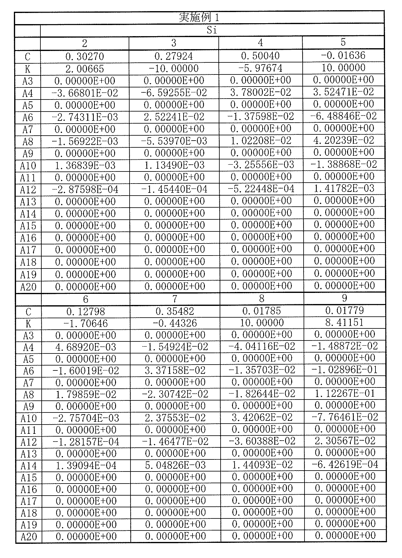
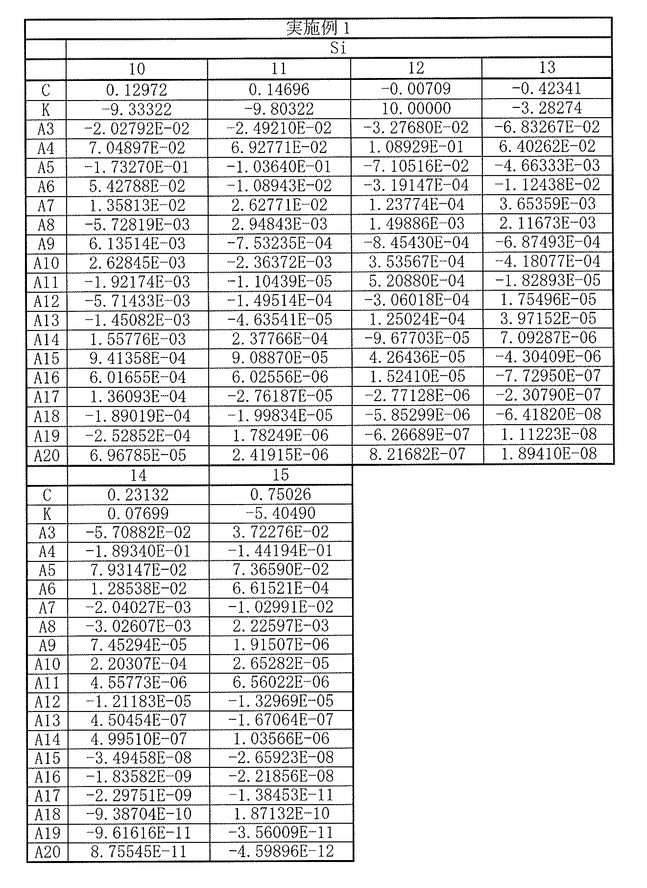
以上の数値実施例1における諸収差を図2に示す。図2には諸収差として、球面収差、非点収差(像面湾曲)、および歪曲収差を示す。これらの各収差図には、d線(587.56nm)を基準波長とした収差を示す。球面収差図には、g線(435.84nm)、およびC線(656.27nm)に対する収差も示す。非点収差図において、実線(S)はサジタル像面、破線(T)はタンジェンシャル像面における値を示す。以降の他の数値実施例における収差図についても同様である。
The various aberrations in the numerical example 1 described above are shown in FIG. FIG. 2 shows spherical aberration, astigmatism (field curvature), and distortion as various aberrations. Each of these aberration diagrams shows aberrations with the d-line (587.56 nm) as a reference wavelength. The spherical aberration diagram also shows aberrations with respect to g-line (435.84 nm) and C-line (656.27 nm). In the graph showing astigmatism, a solid line (S) indicates a value on a sagittal image plane, and a broken line (T) indicates a value on a tangential image plane. The same applies to aberration diagrams in other numerical examples.
各収差図から分かるように、数値実施例1に係る撮像レンズ1は、小型でありながらも諸収差が良好に補正され、優れた光学性能を有していることは明らかである。
As can be seen from the respective aberration diagrams, it is clear that the imaging lens 1 according to Numerical Example 1 has a good optical performance with various aberrations corrected satisfactorily even though it is small.
[数値実施例2]
[表4]に、図3に示した撮像レンズ2に具体的な数値を適用した数値実施例2の基本的なレンズデータを示す。 [Numerical Example 2]
[Table 4] shows basic lens data of Numerical Example 2 in which specific numerical values are applied to theimaging lens 2 shown in FIG.
[表4]に、図3に示した撮像レンズ2に具体的な数値を適用した数値実施例2の基本的なレンズデータを示す。 [Numerical Example 2]
[Table 4] shows basic lens data of Numerical Example 2 in which specific numerical values are applied to the
数値実施例2に係る撮像レンズ2において、第1レンズL1~第7レンズL7の各レンズの両面は非球面形状となっている。[表5],[表6]には、それらの非球面の形状を表す係数の値を示す。
In the imaging lens 2 according to Numerical Example 2, both surfaces of each of the first lens L1 to the seventh lens L7 are aspherical. [Table 5] and [Table 6] show coefficient values representing the shape of the aspheric surfaces.
数値実施例2に係る撮像レンズ2では、第1レンズL1は、光軸近傍において正の屈折力を有している。第2レンズL2は、光軸近傍において正の屈折力を有している。第3レンズL3は、光軸近傍において負の屈折力を有している。第4レンズL4は、光軸近傍において正の屈折力を有している。第5レンズL5は、光軸近傍において負の屈折力を有している。第6レンズL6は、光軸近傍において正の屈折力を有している。第7レンズL7は、光軸近傍において負の屈折力を有している。
In the imaging lens 2 according to Numerical Example 2, the first lens L1 has a positive refractive power in the vicinity of the optical axis. The second lens L2 has a positive refractive power in the vicinity of the optical axis. The third lens L3 has a negative refractive power in the vicinity of the optical axis. The fourth lens L4 has a positive refractive power in the vicinity of the optical axis. The fifth lens L5 has a negative refractive power in the vicinity of the optical axis. The sixth lens L6 has a positive refractive power in the vicinity of the optical axis. The seventh lens L7 has a negative refractive power in the vicinity of the optical axis.
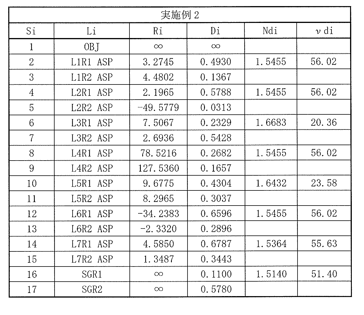
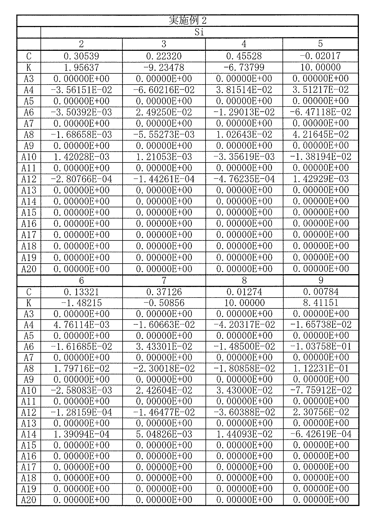

以上の数値実施例2における諸収差を図4に示す。各収差図から分かるように、小型でありながらも諸収差が良好に補正され、優れた光学性能を有していることは明らかである。
Various aberrations in the above numerical example 2 are shown in FIG. As can be seen from the respective aberration diagrams, it is clear that various aberrations are corrected well and the optical performance is excellent although it is small.
[数値実施例3]
[表7]に、図5に示した撮像レンズ3に具体的な数値を適用した数値実施例3の基本的なレンズデータを示す。 [Numerical Example 3]
[Table 7] shows basic lens data of Numerical Example 3 in which specific numerical values are applied to theimaging lens 3 shown in FIG.
[表7]に、図5に示した撮像レンズ3に具体的な数値を適用した数値実施例3の基本的なレンズデータを示す。 [Numerical Example 3]
[Table 7] shows basic lens data of Numerical Example 3 in which specific numerical values are applied to the
数値実施例3に係る撮像レンズ3において、第1レンズL1~第7レンズL7の各レンズの両面は非球面形状となっている。[表8],[表9]には、それらの非球面の形状を表す係数の値を示す。
In the imaging lens 3 according to Numerical Example 3, both surfaces of each of the first lens L1 to the seventh lens L7 are aspherical. [Table 8] and [Table 9] show coefficient values representing the shape of the aspheric surfaces.
数値実施例3に係る撮像レンズ3では、第1レンズL1は、光軸近傍において負の屈折力を有している。第2レンズL2は、光軸近傍において正の屈折力を有している。第3レンズL3は、光軸近傍において負の屈折力を有している。第4レンズL4は、光軸近傍において負の屈折力を有している。第5レンズL5は、光軸近傍において正の屈折力を有している。第6レンズL6は、光軸近傍において正の屈折力を有している。第7レンズL7は、光軸近傍において負の屈折力を有している。
In the imaging lens 3 according to Numerical Example 3, the first lens L1 has a negative refractive power in the vicinity of the optical axis. The second lens L2 has a positive refractive power in the vicinity of the optical axis. The third lens L3 has a negative refractive power in the vicinity of the optical axis. The fourth lens L4 has a negative refractive power in the vicinity of the optical axis. The fifth lens L5 has a positive refractive power in the vicinity of the optical axis. The sixth lens L6 has a positive refractive power in the vicinity of the optical axis. The seventh lens L7 has a negative refractive power in the vicinity of the optical axis.
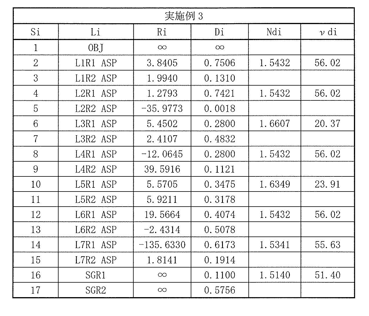
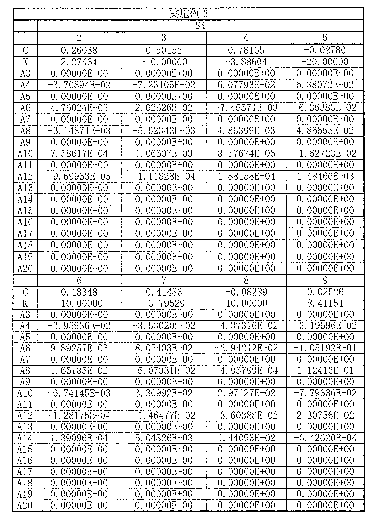

以上の数値実施例3における諸収差を図6に示す。各収差図から分かるように、小型でありながらも諸収差が良好に補正され、優れた光学性能を有していることは明らかである。
Various aberrations in the above numerical example 3 are shown in FIG. As can be seen from the respective aberration diagrams, it is clear that various aberrations are corrected well and the optical performance is excellent although it is small.
[数値実施例4]
[表10]に、図7に示した撮像レンズ4に具体的な数値を適用した数値実施例4の基本的なレンズデータを示す。 [Numerical Example 4]
[Table 10] shows basic lens data of Numerical Example 4 in which specific numerical values are applied to the imaging lens 4 shown in FIG.
[表10]に、図7に示した撮像レンズ4に具体的な数値を適用した数値実施例4の基本的なレンズデータを示す。 [Numerical Example 4]
[Table 10] shows basic lens data of Numerical Example 4 in which specific numerical values are applied to the imaging lens 4 shown in FIG.
数値実施例4に係る撮像レンズ4において、第1レンズL1~第7レンズL7の各レンズの両面は非球面形状となっている。[表11],[表12]には、それらの非球面の形状を表す係数の値を示す。
In the imaging lens 4 according to Numerical Example 4, both surfaces of each of the first lens L1 to the seventh lens L7 are aspherical. [Table 11] and [Table 12] show values of coefficients representing the shape of the aspheric surfaces.
数値実施例4に係る撮像レンズ4では、第1レンズL1は、光軸近傍において正の屈折力を有している。第2レンズL2は、光軸近傍において正の屈折力を有している。第3レンズL3は、光軸近傍において負の屈折力を有している。第4レンズL4は、光軸近傍において正の屈折力を有している。第5レンズL5は、光軸近傍において負の屈折力を有している。第6レンズL6は、光軸近傍において正の屈折力を有している。第7レンズL7は、光軸近傍において負の屈折力を有している。
In the imaging lens 4 according to Numerical Example 4, the first lens L1 has a positive refractive power in the vicinity of the optical axis. The second lens L2 has a positive refractive power in the vicinity of the optical axis. The third lens L3 has a negative refractive power in the vicinity of the optical axis. The fourth lens L4 has a positive refractive power in the vicinity of the optical axis. The fifth lens L5 has a negative refractive power in the vicinity of the optical axis. The sixth lens L6 has a positive refractive power in the vicinity of the optical axis. The seventh lens L7 has a negative refractive power in the vicinity of the optical axis.
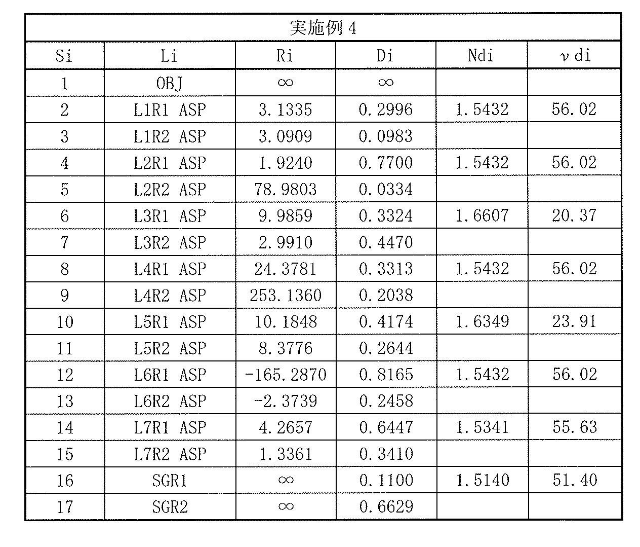
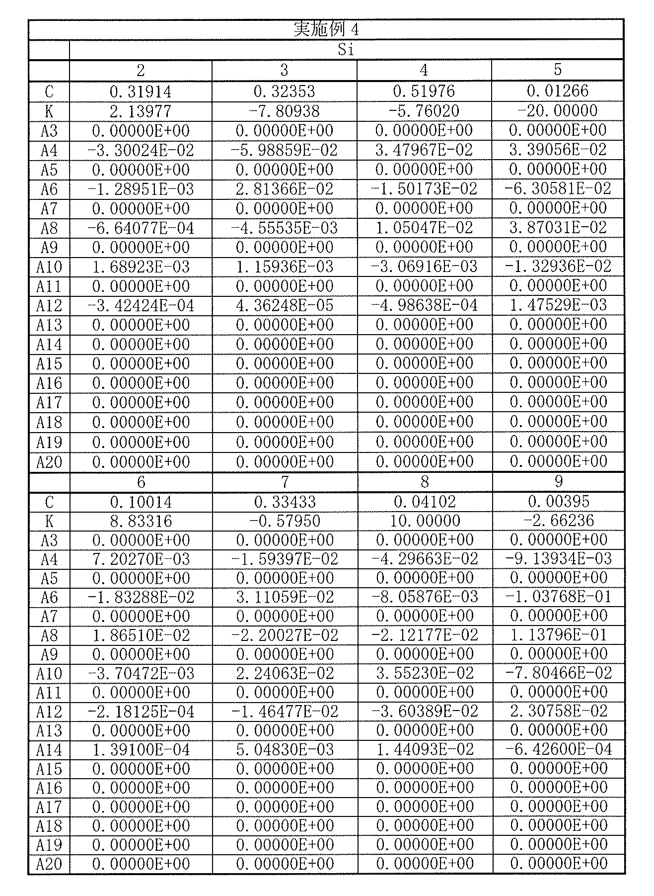
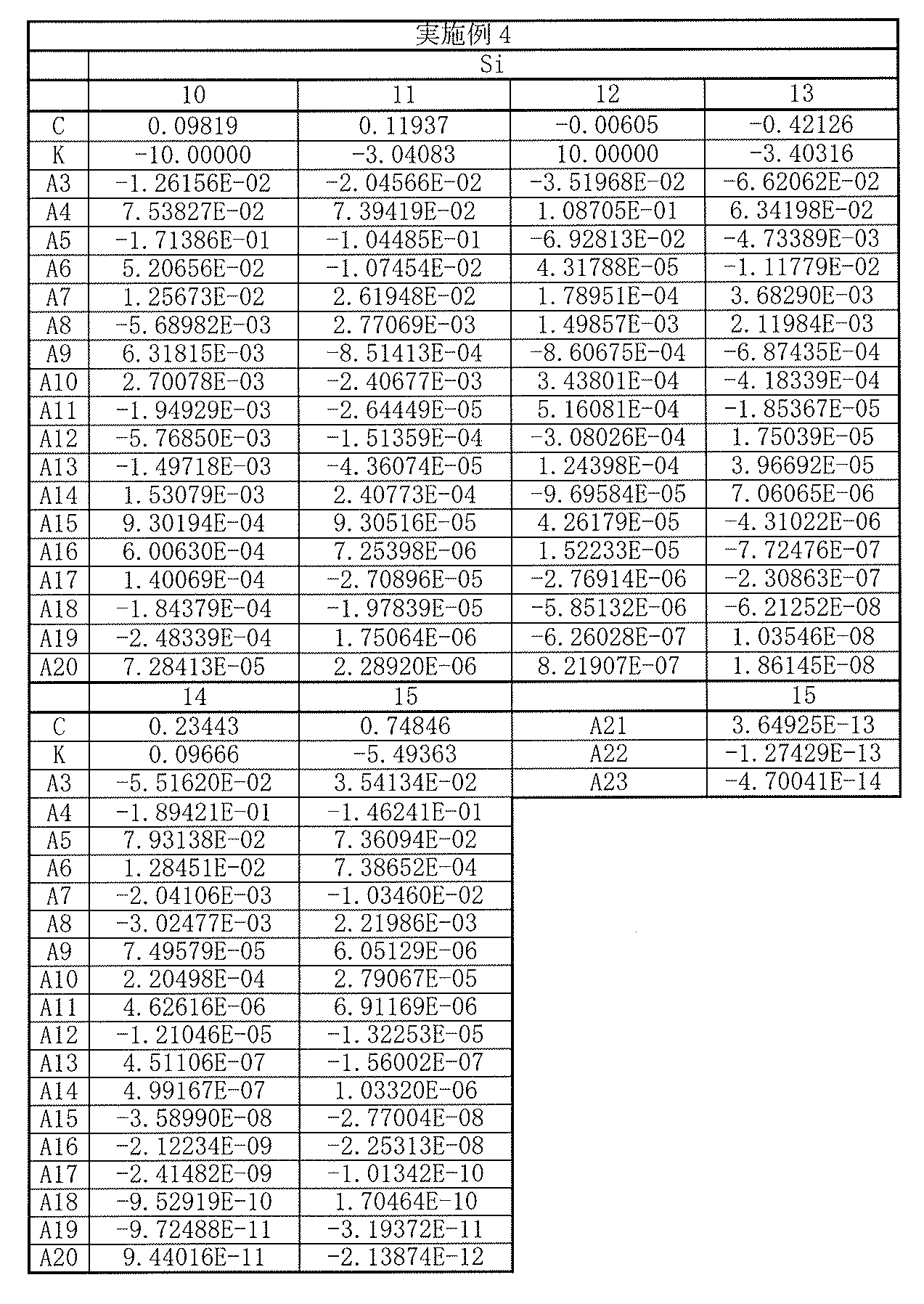
以上の数値実施例4における諸収差を図8に示す。各収差図から分かるように、小型でありながらも諸収差が良好に補正され、優れた光学性能を有していることは明らかである。
The various aberrations in the above numerical example 4 are shown in FIG. As can be seen from the respective aberration diagrams, it is clear that various aberrations are corrected well and the optical performance is excellent although it is small.
[数値実施例5]
[表13]に、図9に示した撮像レンズ5に具体的な数値を適用した数値実施例5の基本的なレンズデータを示す。 [Numerical Example 5]
Table 13 shows basic lens data of Numerical Example 5 in which specific numerical values are applied to theimaging lens 5 shown in FIG.
[表13]に、図9に示した撮像レンズ5に具体的な数値を適用した数値実施例5の基本的なレンズデータを示す。 [Numerical Example 5]
Table 13 shows basic lens data of Numerical Example 5 in which specific numerical values are applied to the
数値実施例5に係る撮像レンズ5において、第1レンズL1~第7レンズL7の各レンズの両面は非球面形状となっている。[表14],[表15]には、それらの非球面の形状を表す係数の値を示す。
In the imaging lens 5 according to Numerical Example 5, both surfaces of each of the first lens L1 to the seventh lens L7 are aspherical. [Table 14] and [Table 15] show values of coefficients representing the shape of the aspheric surfaces.
数値実施例5に係る撮像レンズ5では、第1レンズL1は、光軸近傍において正の屈折力を有している。第2レンズL2は、光軸近傍において正の屈折力を有している。第3レンズL3は、光軸近傍において負の屈折力を有している。第4レンズL4は、光軸近傍において負の屈折力を有している。第5レンズL5は、光軸近傍において負の屈折力を有している。第6レンズL6は、光軸近傍において正の屈折力を有している。第7レンズL7は、光軸近傍において負の屈折力を有している。
In the imaging lens 5 according to Numerical Example 5, the first lens L1 has a positive refractive power in the vicinity of the optical axis. The second lens L2 has a positive refractive power in the vicinity of the optical axis. The third lens L3 has a negative refractive power in the vicinity of the optical axis. The fourth lens L4 has a negative refractive power in the vicinity of the optical axis. The fifth lens L5 has a negative refractive power in the vicinity of the optical axis. The sixth lens L6 has a positive refractive power in the vicinity of the optical axis. The seventh lens L7 has a negative refractive power in the vicinity of the optical axis.
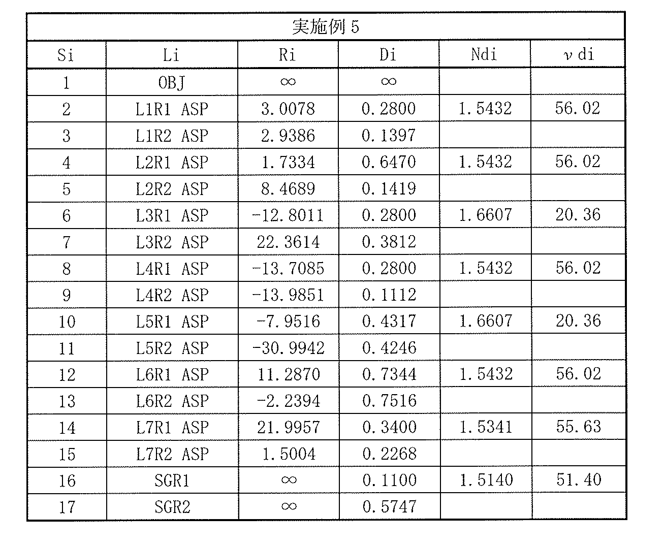
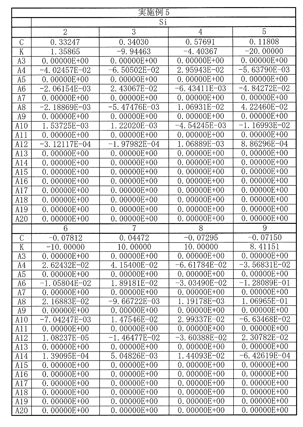

以上の数値実施例5における諸収差を図10に示す。各収差図から分かるように、小型でありながらも諸収差が良好に補正され、優れた光学性能を有していることは明らかである。
The various aberrations in the above numerical example 5 are shown in FIG. As can be seen from the respective aberration diagrams, it is clear that various aberrations are corrected well and the optical performance is excellent although it is small.
[数値実施例6]
[表16]に、図11に示した撮像レンズ6に具体的な数値を適用した数値実施例6の基本的なレンズデータを示す。 [Numerical Example 6]
[Table 16] shows basic lens data of Numerical Example 6 in which specific numerical values are applied to theimaging lens 6 shown in FIG.
[表16]に、図11に示した撮像レンズ6に具体的な数値を適用した数値実施例6の基本的なレンズデータを示す。 [Numerical Example 6]
[Table 16] shows basic lens data of Numerical Example 6 in which specific numerical values are applied to the
数値実施例6に係る撮像レンズ6において、第1レンズL1~第7レンズL7の各レンズの両面は非球面形状となっている。[表17],[表18]には、それらの非球面の形状を表す係数の値を示す。
In the imaging lens 6 according to Numerical Example 6, both surfaces of each of the first lens L1 to the seventh lens L7 are aspherical. [Table 17] and [Table 18] show values of coefficients representing the shape of the aspheric surfaces.
数値実施例6に係る撮像レンズ6では、第1レンズL1は、光軸近傍において正の屈折力を有している。第2レンズL2は、光軸近傍において正の屈折力を有している。第3レンズL3は、光軸近傍において負の屈折力を有している。第4レンズL4は、光軸近傍において正の屈折力を有している。第5レンズL5は、光軸近傍において正の屈折力を有している。第6レンズL6は、光軸近傍において正の屈折力を有している。第7レンズL7は、光軸近傍において負の屈折力を有している。
In the imaging lens 6 according to Numerical Example 6, the first lens L1 has a positive refractive power in the vicinity of the optical axis. The second lens L2 has a positive refractive power in the vicinity of the optical axis. The third lens L3 has a negative refractive power in the vicinity of the optical axis. The fourth lens L4 has a positive refractive power in the vicinity of the optical axis. The fifth lens L5 has a positive refractive power in the vicinity of the optical axis. The sixth lens L6 has a positive refractive power in the vicinity of the optical axis. The seventh lens L7 has a negative refractive power in the vicinity of the optical axis.
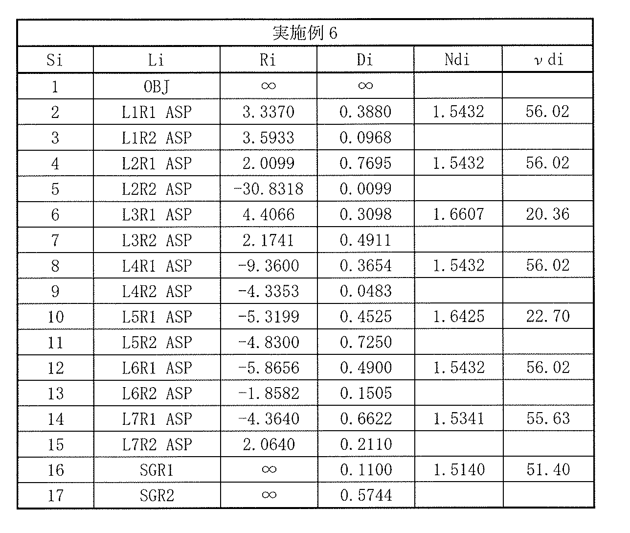


以上の数値実施例6における諸収差を図12に示す。各収差図から分かるように、小型でありながらも諸収差が良好に補正され、優れた光学性能を有していることは明らかである。
Various aberrations in the above numerical example 6 are shown in FIG. As can be seen from the respective aberration diagrams, it is clear that various aberrations are corrected well and the optical performance is excellent although it is small.
[数値実施例7]
[表19]に、図13に示した撮像レンズ7に具体的な数値を適用した数値実施例7の基本的なレンズデータを示す。 [Numerical Example 7]
Table 19 shows basic lens data of Numerical Example 7 in which specific numerical values are applied to theimaging lens 7 shown in FIG.
[表19]に、図13に示した撮像レンズ7に具体的な数値を適用した数値実施例7の基本的なレンズデータを示す。 [Numerical Example 7]
Table 19 shows basic lens data of Numerical Example 7 in which specific numerical values are applied to the
数値実施例7に係る撮像レンズ7において、第1レンズL1~第7レンズL7の各レンズの両面は非球面形状となっている。[表20],[表21]には、それらの非球面の形状を表す係数の値を示す。
In the imaging lens 7 according to Numerical Example 7, both surfaces of each of the first lens L1 to the seventh lens L7 are aspherical. [Table 20] and [Table 21] show coefficient values representing the shape of the aspheric surfaces.
数値実施例7に係る撮像レンズ7では、第1レンズL1は、光軸近傍において正の屈折力を有している。第2レンズL2は、光軸近傍において正の屈折力を有している。第3レンズL3は、光軸近傍において負の屈折力を有している。第4レンズL4は、光軸近傍において正の屈折力を有している。第5レンズL5は、光軸近傍において正の屈折力を有している。第6レンズL6は、光軸近傍において正の屈折力を有している。第7レンズL7は、光軸近傍において負の屈折力を有している。
In the imaging lens 7 according to Numerical Example 7, the first lens L1 has a positive refractive power in the vicinity of the optical axis. The second lens L2 has a positive refractive power in the vicinity of the optical axis. The third lens L3 has a negative refractive power in the vicinity of the optical axis. The fourth lens L4 has a positive refractive power in the vicinity of the optical axis. The fifth lens L5 has a positive refractive power in the vicinity of the optical axis. The sixth lens L6 has a positive refractive power in the vicinity of the optical axis. The seventh lens L7 has a negative refractive power in the vicinity of the optical axis.

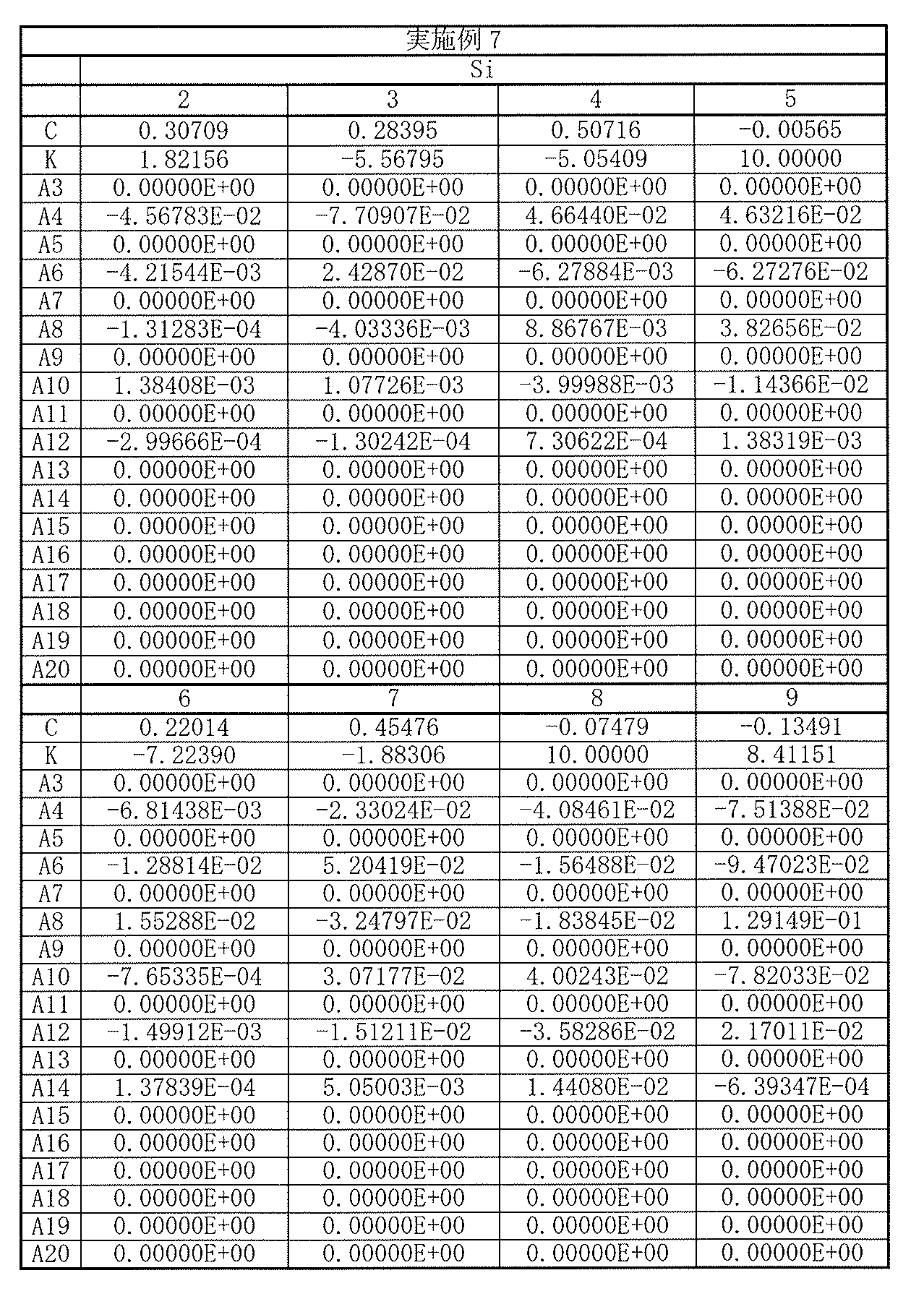

以上の数値実施例7における諸収差を図14に示す。各収差図から分かるように、小型でありながらも諸収差が良好に補正され、優れた光学性能を有していることは明らかである。
The various aberrations in the above numerical example 7 are shown in FIG. As can be seen from the respective aberration diagrams, it is clear that various aberrations are corrected well and the optical performance is excellent although it is small.
[数値実施例8]
[表22]に、図15に示した撮像レンズ8に具体的な数値を適用した数値実施例8の基本的なレンズデータを示す。 [Numerical Example 8]
[Table 22] shows basic lens data of Numerical Example 8 in which specific numerical values are applied to theimaging lens 8 shown in FIG.
[表22]に、図15に示した撮像レンズ8に具体的な数値を適用した数値実施例8の基本的なレンズデータを示す。 [Numerical Example 8]
[Table 22] shows basic lens data of Numerical Example 8 in which specific numerical values are applied to the
数値実施例8に係る撮像レンズ8において、第1レンズL1~第7レンズL7の各レンズの両面は非球面形状となっている。[表23],[表24]には、それらの非球面の形状を表す係数の値を示す。
In the imaging lens 8 according to Numerical Example 8, both surfaces of each of the first lens L1 to the seventh lens L7 are aspherical. [Table 23] and [Table 24] show values of coefficients representing the shape of the aspheric surfaces.
数値実施例8に係る撮像レンズ8では、第1レンズL1は、光軸近傍において正の屈折力を有している。第2レンズL2は、光軸近傍において正の屈折力を有している。第3レンズL3は、光軸近傍において負の屈折力を有している。第4レンズL4は、光軸近傍において負の屈折力を有している。第5レンズL5は、光軸近傍において負の屈折力を有している。第6レンズL6は、光軸近傍において正の屈折力を有している。第7レンズL7は、光軸近傍において負の屈折力を有している。
In the imaging lens 8 according to Numerical Example 8, the first lens L1 has a positive refractive power in the vicinity of the optical axis. The second lens L2 has a positive refractive power in the vicinity of the optical axis. The third lens L3 has a negative refractive power in the vicinity of the optical axis. The fourth lens L4 has a negative refractive power in the vicinity of the optical axis. The fifth lens L5 has a negative refractive power in the vicinity of the optical axis. The sixth lens L6 has a positive refractive power in the vicinity of the optical axis. The seventh lens L7 has a negative refractive power in the vicinity of the optical axis.

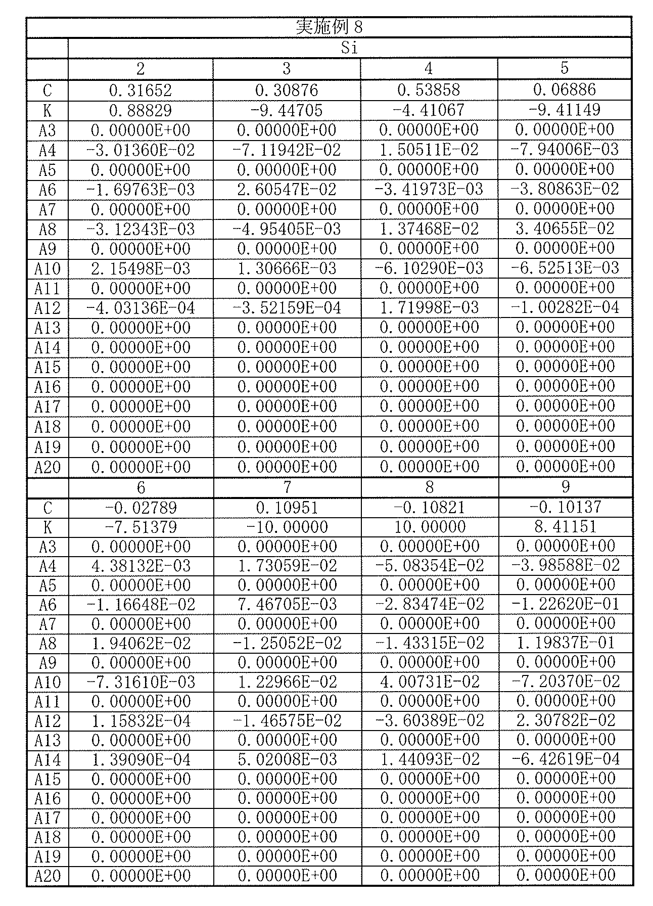
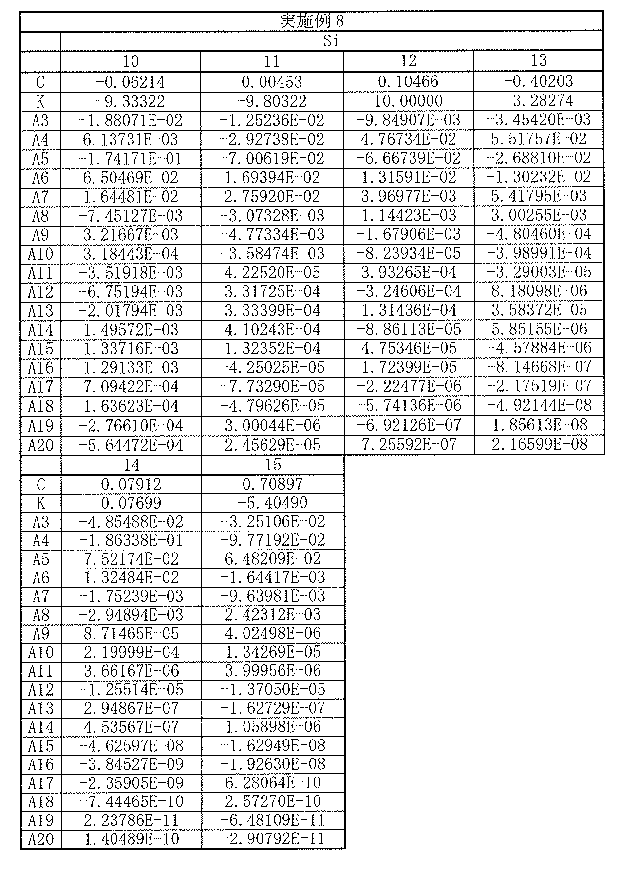
以上の数値実施例8における諸収差を図16に示す。各収差図から分かるように、小型でありながらも諸収差が良好に補正され、優れた光学性能を有していることは明らかである。
The various aberrations in the above numerical example 8 are shown in FIG. As can be seen from the respective aberration diagrams, it is clear that various aberrations are corrected well and the optical performance is excellent although it is small.
[数値実施例9]
[表25]に、図17に示した撮像レンズ9に具体的な数値を適用した数値実施例9の基本的なレンズデータを示す。 [Numerical Example 9]
Table 25 shows basic lens data of Numerical Example 9 in which specific numerical values are applied to theimaging lens 9 shown in FIG.
[表25]に、図17に示した撮像レンズ9に具体的な数値を適用した数値実施例9の基本的なレンズデータを示す。 [Numerical Example 9]
Table 25 shows basic lens data of Numerical Example 9 in which specific numerical values are applied to the
数値実施例9に係る撮像レンズ9において、第1レンズL1~第7レンズL7の各レンズの両面は非球面形状となっている。[表26],[表27]には、それらの非球面の形状を表す係数の値を示す。
In the imaging lens 9 according to Numerical Example 9, both surfaces of each of the first lens L1 to the seventh lens L7 are aspherical. [Table 26] and [Table 27] show coefficient values representing the shape of the aspheric surfaces.
数値実施例9に係る撮像レンズ9では、第1レンズL1は、光軸近傍において正の屈折力を有している。第2レンズL2は、光軸近傍において正の屈折力を有している。第3レンズL3は、光軸近傍において負の屈折力を有している。第4レンズL4は、光軸近傍において正の屈折力を有している。第5レンズL5は、光軸近傍において負の屈折力を有している。第6レンズL6は、光軸近傍において正の屈折力を有している。第7レンズL7は、光軸近傍において負の屈折力を有している。
In the imaging lens 9 according to Numerical Example 9, the first lens L1 has a positive refractive power in the vicinity of the optical axis. The second lens L2 has a positive refractive power in the vicinity of the optical axis. The third lens L3 has a negative refractive power in the vicinity of the optical axis. The fourth lens L4 has a positive refractive power in the vicinity of the optical axis. The fifth lens L5 has a negative refractive power in the vicinity of the optical axis. The sixth lens L6 has a positive refractive power in the vicinity of the optical axis. The seventh lens L7 has a negative refractive power in the vicinity of the optical axis.
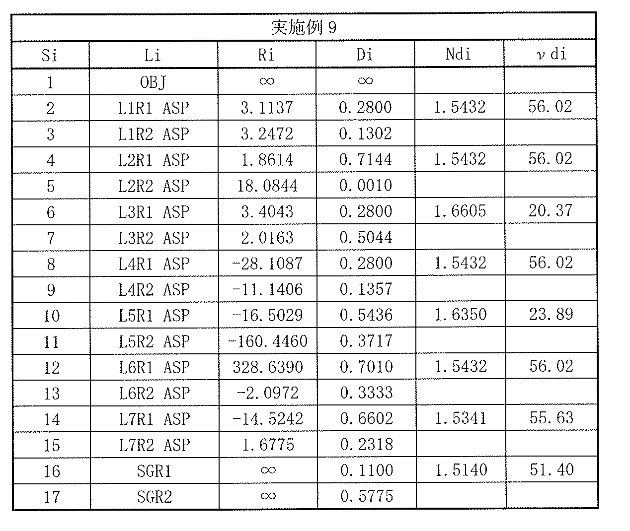
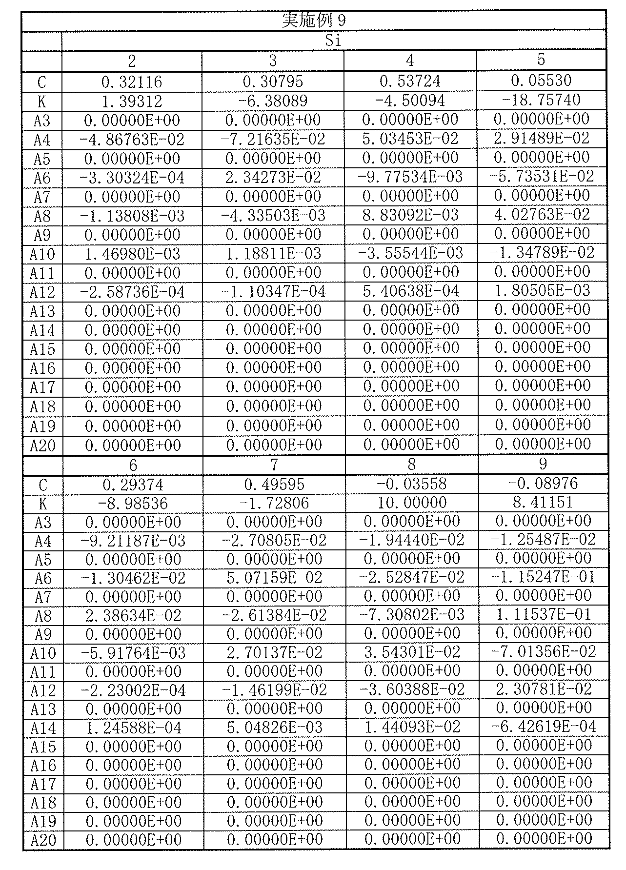
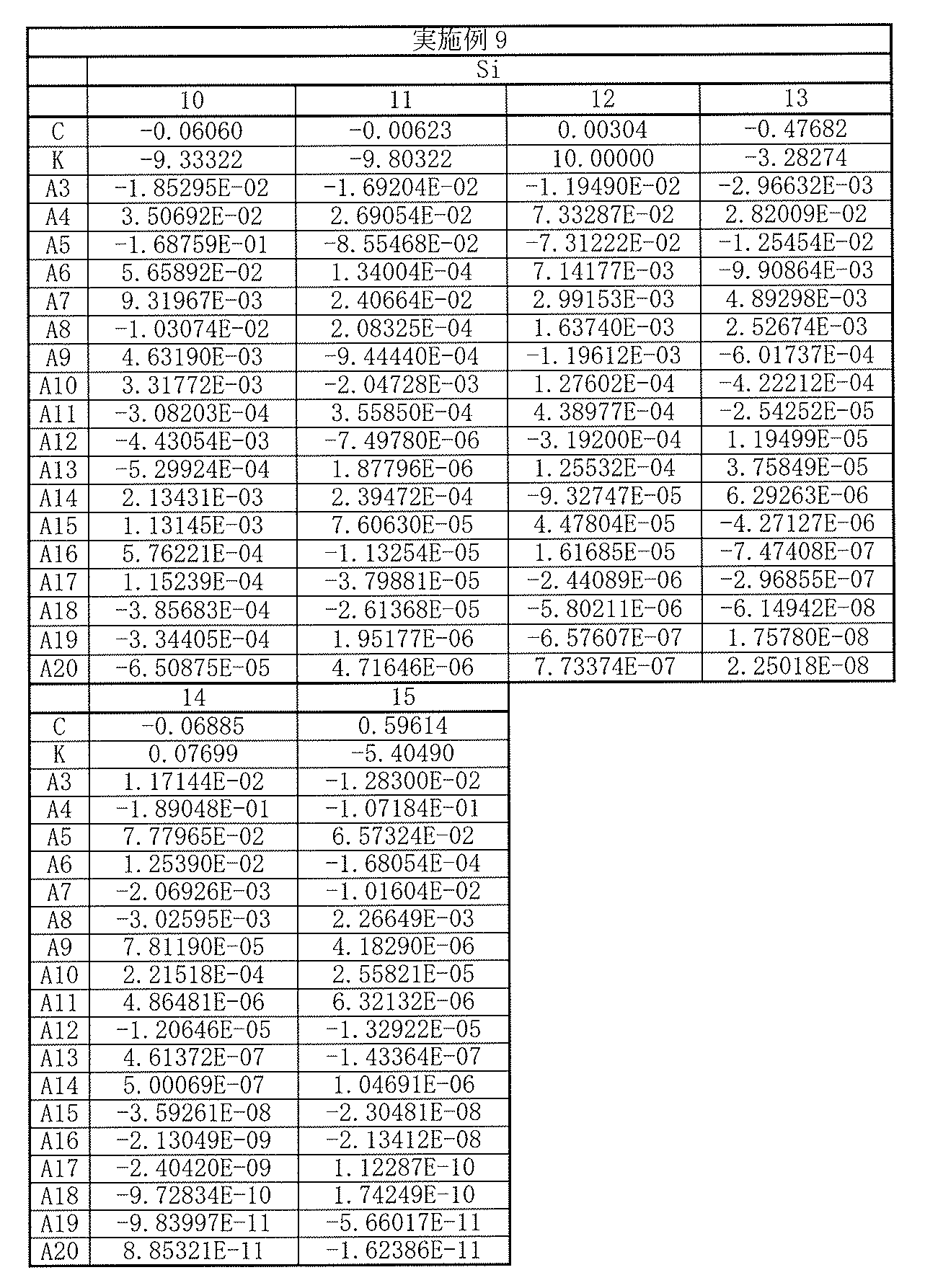
以上の数値実施例9における諸収差を図18に示す。各収差図から分かるように、小型でありながらも諸収差が良好に補正され、優れた光学性能を有していることは明らかである。
The various aberrations in the above numerical example 9 are shown in FIG. As can be seen from the respective aberration diagrams, it is clear that various aberrations are corrected well and the optical performance is excellent although it is small.
[数値実施例10]
[表28]に、図19に示した撮像レンズ10に具体的な数値を適用した数値実施例10の基本的なレンズデータを示す。 [Numerical Example 10]
Table 28 shows basic lens data of Numerical Example 10 in which specific numerical values are applied to theimaging lens 10 shown in FIG.
[表28]に、図19に示した撮像レンズ10に具体的な数値を適用した数値実施例10の基本的なレンズデータを示す。 [Numerical Example 10]
Table 28 shows basic lens data of Numerical Example 10 in which specific numerical values are applied to the
数値実施例10に係る撮像レンズ10において、第1レンズL1~第7レンズL7の各レンズの両面は非球面形状となっている。[表29],[表30]には、それらの非球面の形状を表す係数の値を示す。
In the imaging lens 10 according to Numerical Example 10, both surfaces of each of the first lens L1 to the seventh lens L7 are aspherical. [Table 29] and [Table 30] show coefficient values representing the shape of the aspheric surfaces.
数値実施例10に係る撮像レンズ10では、第1レンズL1は、光軸近傍において正の屈折力を有している。第2レンズL2は、光軸近傍において正の屈折力を有している。第3レンズL3は、光軸近傍において負の屈折力を有している。第4レンズL4は、光軸近傍において負の屈折力を有している。第5レンズL5は、光軸近傍において負の屈折力を有している。第6レンズL6は、光軸近傍において正の屈折力を有している。第7レンズL7は、光軸近傍において負の屈折力を有している。
In the imaging lens 10 according to Numerical Example 10, the first lens L1 has a positive refractive power in the vicinity of the optical axis. The second lens L2 has a positive refractive power in the vicinity of the optical axis. The third lens L3 has a negative refractive power in the vicinity of the optical axis. The fourth lens L4 has a negative refractive power in the vicinity of the optical axis. The fifth lens L5 has a negative refractive power in the vicinity of the optical axis. The sixth lens L6 has a positive refractive power in the vicinity of the optical axis. The seventh lens L7 has a negative refractive power in the vicinity of the optical axis.

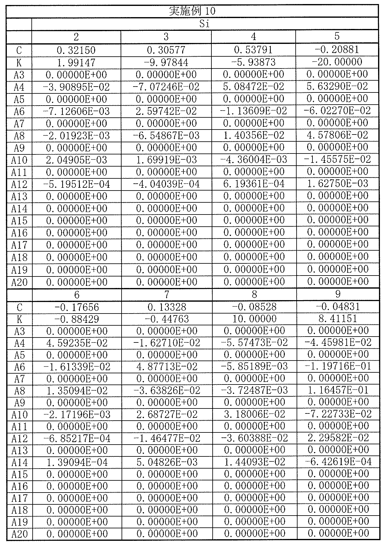

以上の数値実施例10における諸収差を図20に示す。各収差図から分かるように、小型でありながらも諸収差が良好に補正され、優れた光学性能を有していることは明らかである。
The various aberrations in the above numerical example 10 are shown in FIG. As can be seen from the respective aberration diagrams, it is clear that various aberrations are corrected well and the optical performance is excellent although it is small.
[数値実施例11]
[表31]に、図21に示した撮像レンズ11に具体的な数値を適用した数値実施例11の基本的なレンズデータを示す。 [Numerical Example 11]
[Table 31] shows basic lens data of Numerical Example 11 in which specific numerical values are applied to theimaging lens 11 shown in FIG.
[表31]に、図21に示した撮像レンズ11に具体的な数値を適用した数値実施例11の基本的なレンズデータを示す。 [Numerical Example 11]
[Table 31] shows basic lens data of Numerical Example 11 in which specific numerical values are applied to the
数値実施例11に係る撮像レンズ11において、第1レンズL1~第7レンズL7の各レンズの両面は非球面形状となっている。[表32],[表33]には、それらの非球面の形状を表す係数の値を示す。
In the imaging lens 11 according to Numerical Example 11, both surfaces of each of the first lens L1 to the seventh lens L7 are aspherical. [Table 32] and [Table 33] show coefficient values representing the shape of the aspheric surfaces.
数値実施例11に係る撮像レンズ11では、第1レンズL1は、光軸近傍において正の屈折力を有している。第2レンズL2は、光軸近傍において正の屈折力を有している。第3レンズL3は、光軸近傍において負の屈折力を有している。第4レンズL4は、光軸近傍において正の屈折力を有している。第5レンズL5は、光軸近傍において負の屈折力を有している。第6レンズL6は、光軸近傍において正の屈折力を有している。第7レンズL7は、光軸近傍において負の屈折力を有している。
In the imaging lens 11 according to Numerical Example 11, the first lens L1 has a positive refractive power in the vicinity of the optical axis. The second lens L2 has a positive refractive power in the vicinity of the optical axis. The third lens L3 has a negative refractive power in the vicinity of the optical axis. The fourth lens L4 has a positive refractive power in the vicinity of the optical axis. The fifth lens L5 has a negative refractive power in the vicinity of the optical axis. The sixth lens L6 has a positive refractive power in the vicinity of the optical axis. The seventh lens L7 has a negative refractive power in the vicinity of the optical axis.
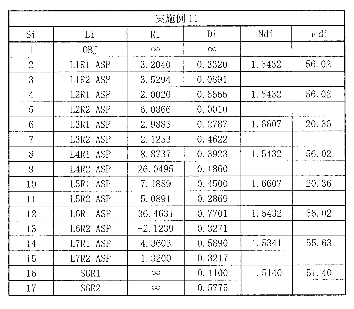
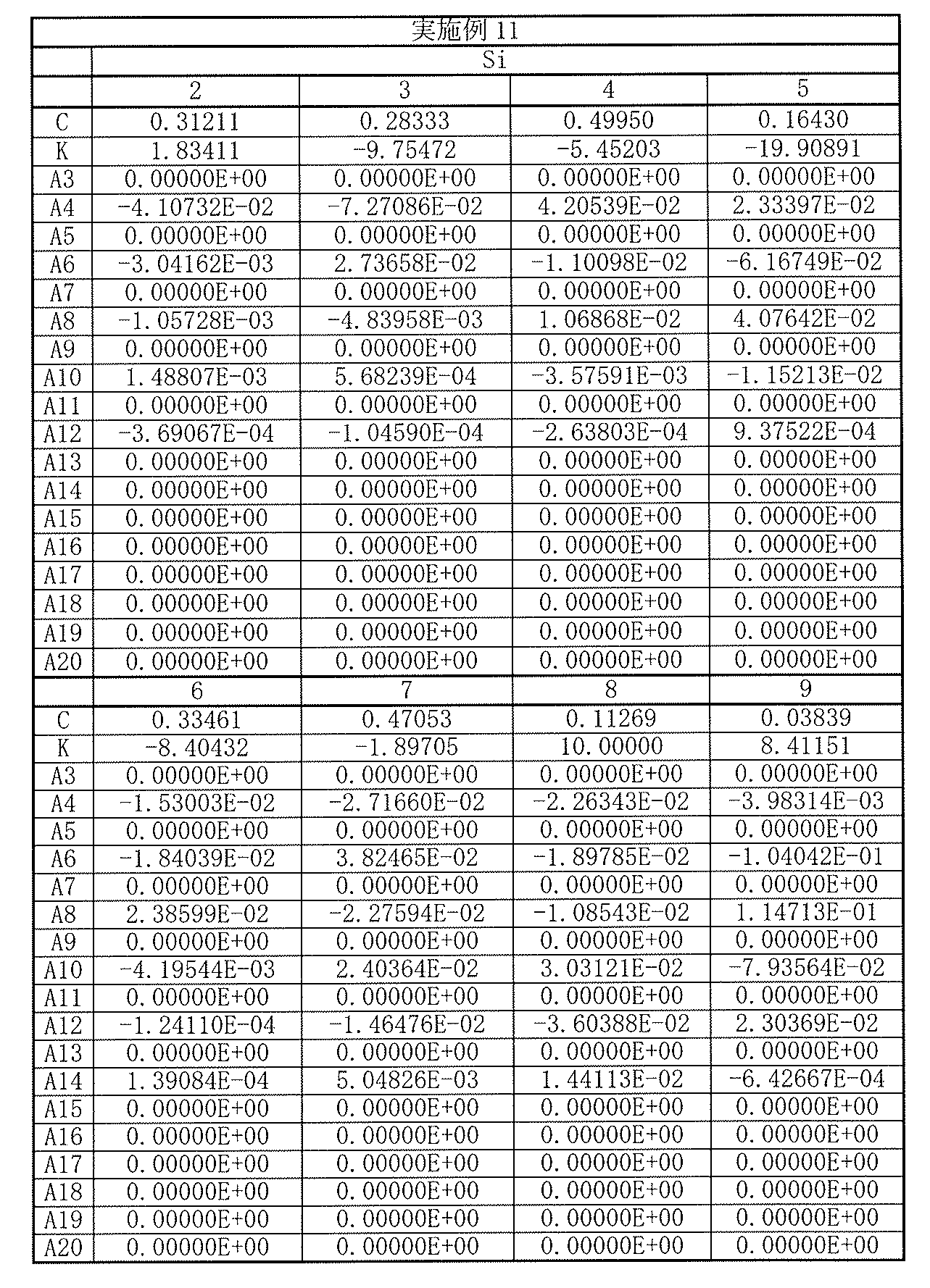
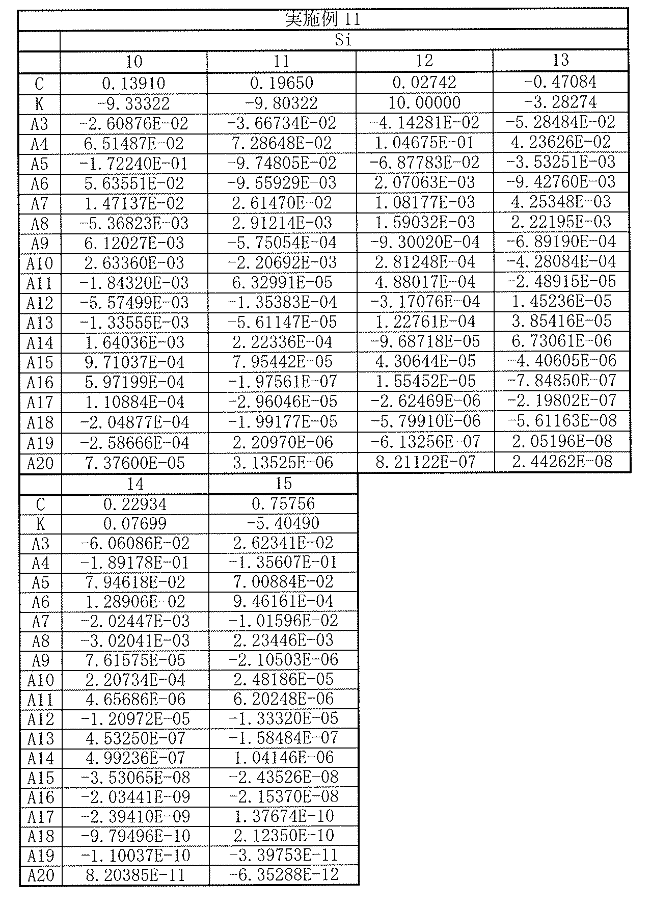
以上の数値実施例11における諸収差を図22に示す。各収差図から分かるように、小型でありながらも諸収差が良好に補正され、優れた光学性能を有していることは明らかである。
The various aberrations in the above numerical example 11 are shown in FIG. As can be seen from the respective aberration diagrams, it is clear that various aberrations are corrected well and the optical performance is excellent although it is small.
[数値実施例12]
[表34]に、図23に示した撮像レンズ12に具体的な数値を適用した数値実施例12の基本的なレンズデータを示す。 [Numerical Example 12]
Table 34 shows basic lens data of Numerical Example 12 in which specific numerical values are applied to theimaging lens 12 shown in FIG.
[表34]に、図23に示した撮像レンズ12に具体的な数値を適用した数値実施例12の基本的なレンズデータを示す。 [Numerical Example 12]
Table 34 shows basic lens data of Numerical Example 12 in which specific numerical values are applied to the
数値実施例12に係る撮像レンズ12において、第1レンズL1~第7レンズL7の各レンズの両面は非球面形状となっている。[表35],[表36]には、それらの非球面の形状を表す係数の値を示す。
In the imaging lens 12 according to Numerical Example 12, both surfaces of the first lens L1 to the seventh lens L7 are aspherical. [Table 35] and [Table 36] show coefficient values representing the shape of the aspheric surfaces.
数値実施例12に係る撮像レンズ12では、第1レンズL1は、光軸近傍において正の屈折力を有している。第2レンズL2は、光軸近傍において正の屈折力を有している。第3レンズL3は、光軸近傍において負の屈折力を有している。第4レンズL4は、光軸近傍において正の屈折力を有している。第5レンズL5は、光軸近傍において正の屈折力を有している。第6レンズL6は、光軸近傍において正の屈折力を有している。第7レンズL7は、光軸近傍において負の屈折力を有している。
In the imaging lens 12 according to Numerical Example 12, the first lens L1 has a positive refractive power in the vicinity of the optical axis. The second lens L2 has a positive refractive power in the vicinity of the optical axis. The third lens L3 has a negative refractive power in the vicinity of the optical axis. The fourth lens L4 has a positive refractive power in the vicinity of the optical axis. The fifth lens L5 has a positive refractive power in the vicinity of the optical axis. The sixth lens L6 has a positive refractive power in the vicinity of the optical axis. The seventh lens L7 has a negative refractive power in the vicinity of the optical axis.
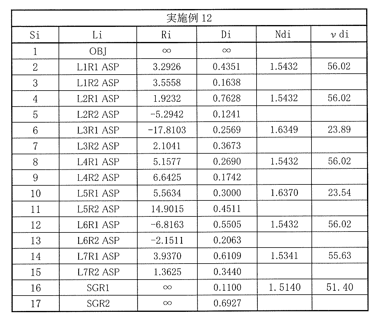
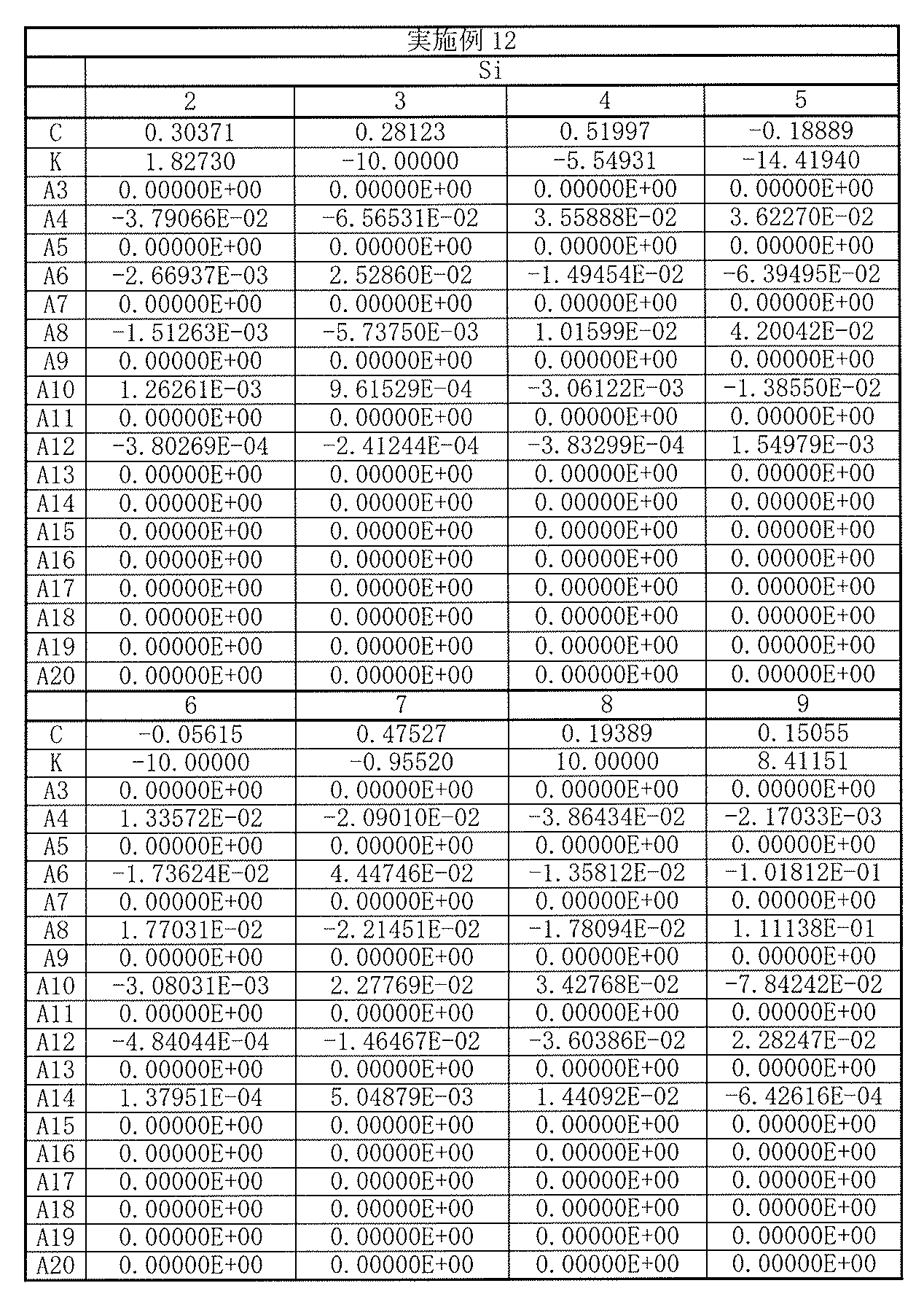
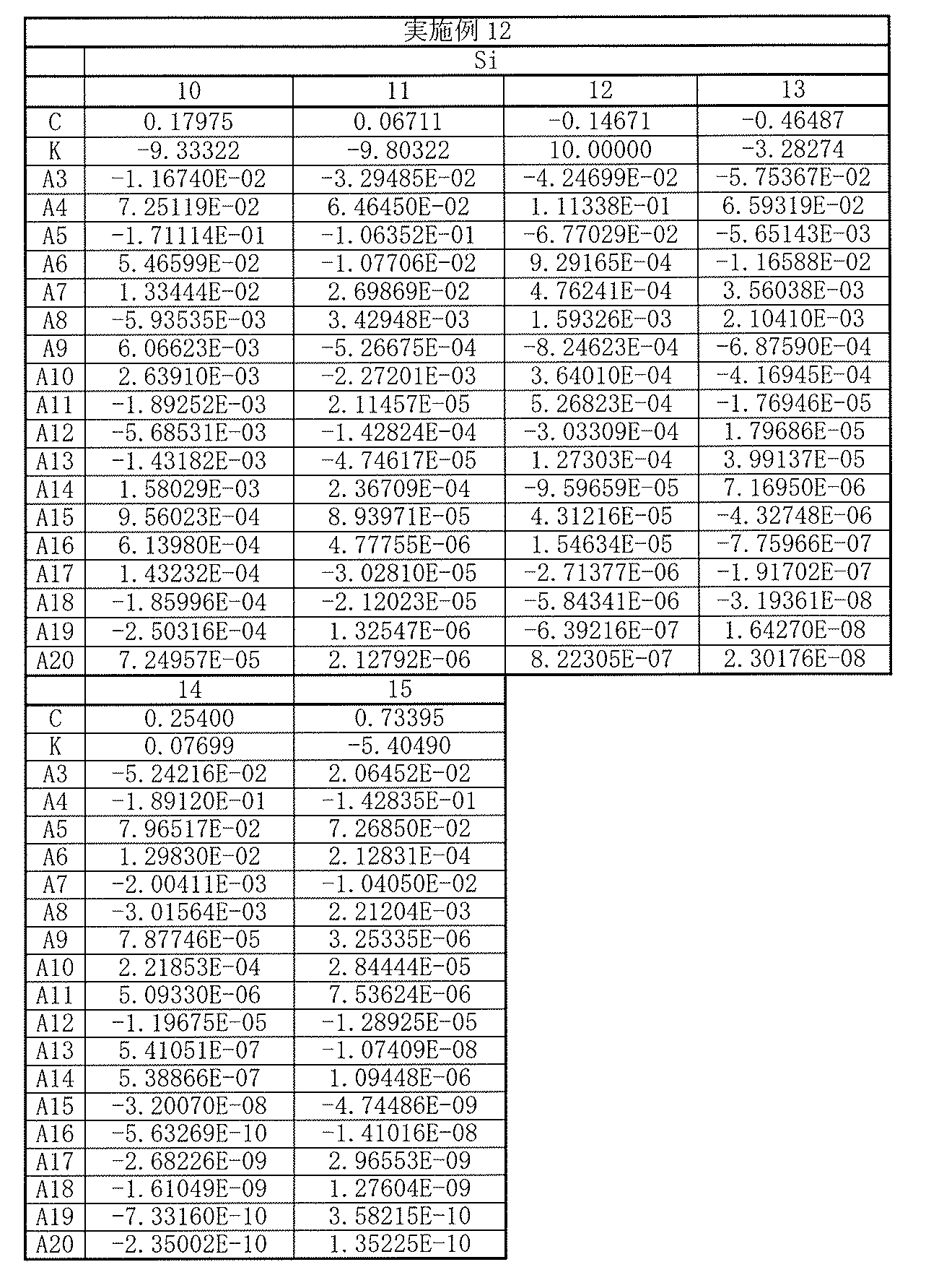
以上の数値実施例12における諸収差を図24に示す。各収差図から分かるように、小型でありながらも諸収差が良好に補正され、優れた光学性能を有していることは明らかである。
Various aberrations in the above numerical example 12 are shown in FIG. As can be seen from the respective aberration diagrams, it is clear that various aberrations are corrected well and the optical performance is excellent although it is small.
[数値実施例13]
[表37]に、図25に示した撮像レンズ13に具体的な数値を適用した数値実施例13の基本的なレンズデータを示す。 [Numerical Example 13]
Table 37 shows basic lens data of Numerical Example 13 in which specific numerical values are applied to theimaging lens 13 shown in FIG.
[表37]に、図25に示した撮像レンズ13に具体的な数値を適用した数値実施例13の基本的なレンズデータを示す。 [Numerical Example 13]
Table 37 shows basic lens data of Numerical Example 13 in which specific numerical values are applied to the
数値実施例13に係る撮像レンズ13において、第1レンズL1~第7レンズL7の各レンズの両面は非球面形状となっている。[表38],[表39]には、それらの非球面の形状を表す係数の値を示す。
In the imaging lens 13 according to Numerical Example 13, both surfaces of each of the first lens L1 to the seventh lens L7 are aspherical. [Table 38] and [Table 39] show coefficient values representing the shape of the aspheric surfaces.
数値実施例13に係る撮像レンズ13では、第1レンズL1は、光軸近傍において正の屈折力を有している。第2レンズL2は、光軸近傍において正の屈折力を有している。第3レンズL3は、光軸近傍において負の屈折力を有している。第4レンズL4は、光軸近傍において正の屈折力を有している。第5レンズL5は、光軸近傍において負の屈折力を有している。第6レンズL6は、光軸近傍において正の屈折力を有している。第7レンズL7は、光軸近傍において負の屈折力を有している。
In the imaging lens 13 according to Numerical Example 13, the first lens L1 has a positive refractive power in the vicinity of the optical axis. The second lens L2 has a positive refractive power in the vicinity of the optical axis. The third lens L3 has a negative refractive power in the vicinity of the optical axis. The fourth lens L4 has a positive refractive power in the vicinity of the optical axis. The fifth lens L5 has a negative refractive power in the vicinity of the optical axis. The sixth lens L6 has a positive refractive power in the vicinity of the optical axis. The seventh lens L7 has a negative refractive power in the vicinity of the optical axis.
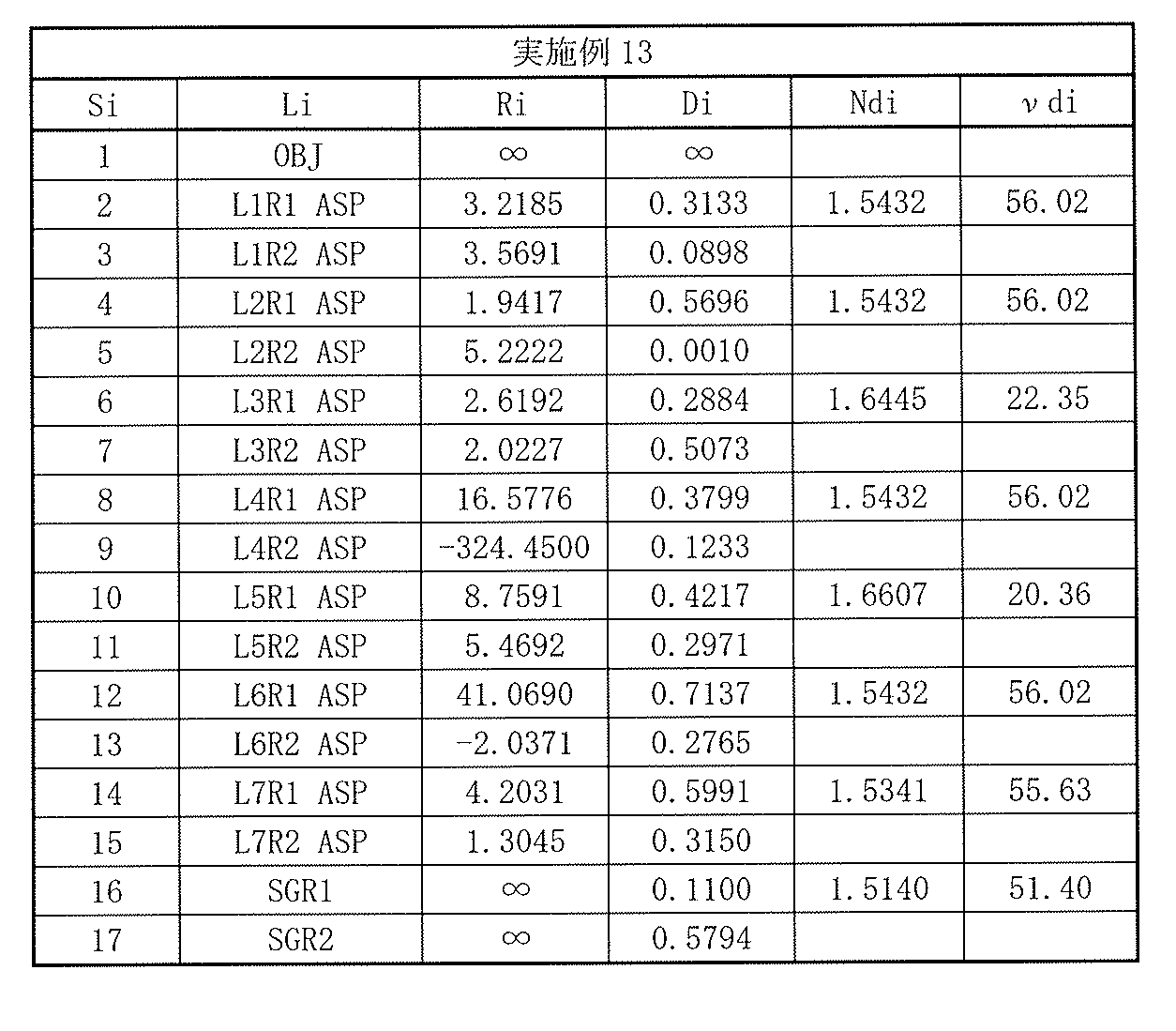
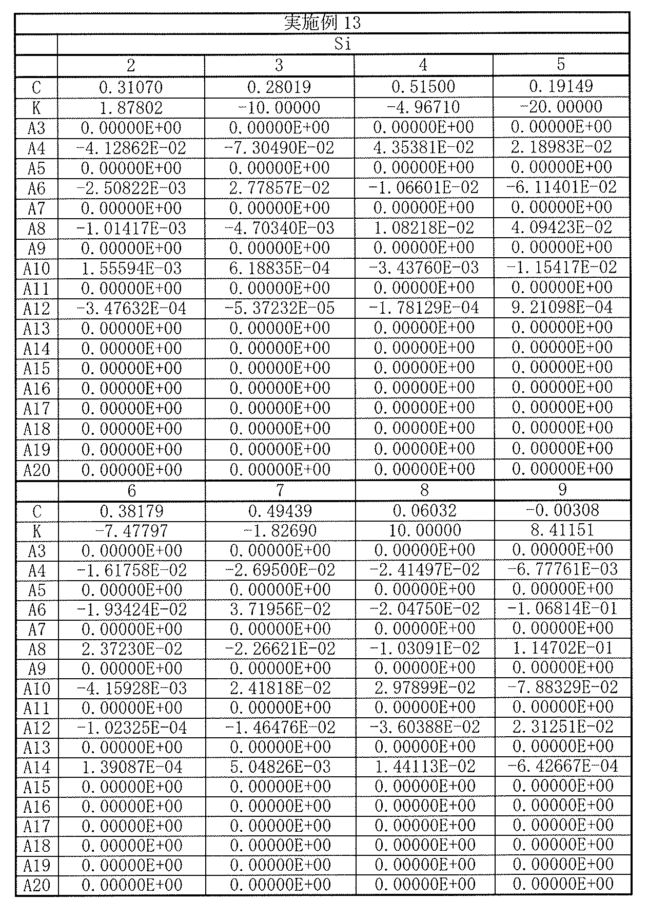

以上の数値実施例13における諸収差を図26に示す。各収差図から分かるように、小型でありながらも諸収差が良好に補正され、優れた光学性能を有していることは明らかである。
Various aberrations in the above numerical example 13 are shown in FIG. As can be seen from the respective aberration diagrams, it is clear that various aberrations are corrected well and the optical performance is excellent although it is small.
[数値実施例14]
[表40]に、図27に示した撮像レンズ14に具体的な数値を適用した数値実施例14の基本的なレンズデータを示す。 [Numerical Example 14]
[Table 40] shows basic lens data of Numerical Example 14 in which specific numerical values are applied to theimaging lens 14 shown in FIG.
[表40]に、図27に示した撮像レンズ14に具体的な数値を適用した数値実施例14の基本的なレンズデータを示す。 [Numerical Example 14]
[Table 40] shows basic lens data of Numerical Example 14 in which specific numerical values are applied to the
数値実施例14に係る撮像レンズ14において、第1レンズL1~第7レンズL7の各レンズの両面は非球面形状となっている。[表41],[表42]には、それらの非球面の形状を表す係数の値を示す。
In the imaging lens 14 according to Numerical Example 14, both surfaces of each of the first lens L1 to the seventh lens L7 are aspherical. [Table 41] and [Table 42] show values of coefficients representing the shape of the aspheric surfaces.
数値実施例14に係る撮像レンズ14では、第1レンズL1は、光軸近傍において正の屈折力を有している。第2レンズL2は、光軸近傍において正の屈折力を有している。第3レンズL3は、光軸近傍において負の屈折力を有している。第4レンズL4は、光軸近傍において負の屈折力を有している。第5レンズL5は、光軸近傍において負の屈折力を有している。第6レンズL6は、光軸近傍において正の屈折力を有している。第7レンズL7は、光軸近傍において負の屈折力を有している。
In the imaging lens 14 according to Numerical Example 14, the first lens L1 has a positive refractive power in the vicinity of the optical axis. The second lens L2 has a positive refractive power in the vicinity of the optical axis. The third lens L3 has a negative refractive power in the vicinity of the optical axis. The fourth lens L4 has a negative refractive power in the vicinity of the optical axis. The fifth lens L5 has a negative refractive power in the vicinity of the optical axis. The sixth lens L6 has a positive refractive power in the vicinity of the optical axis. The seventh lens L7 has a negative refractive power in the vicinity of the optical axis.
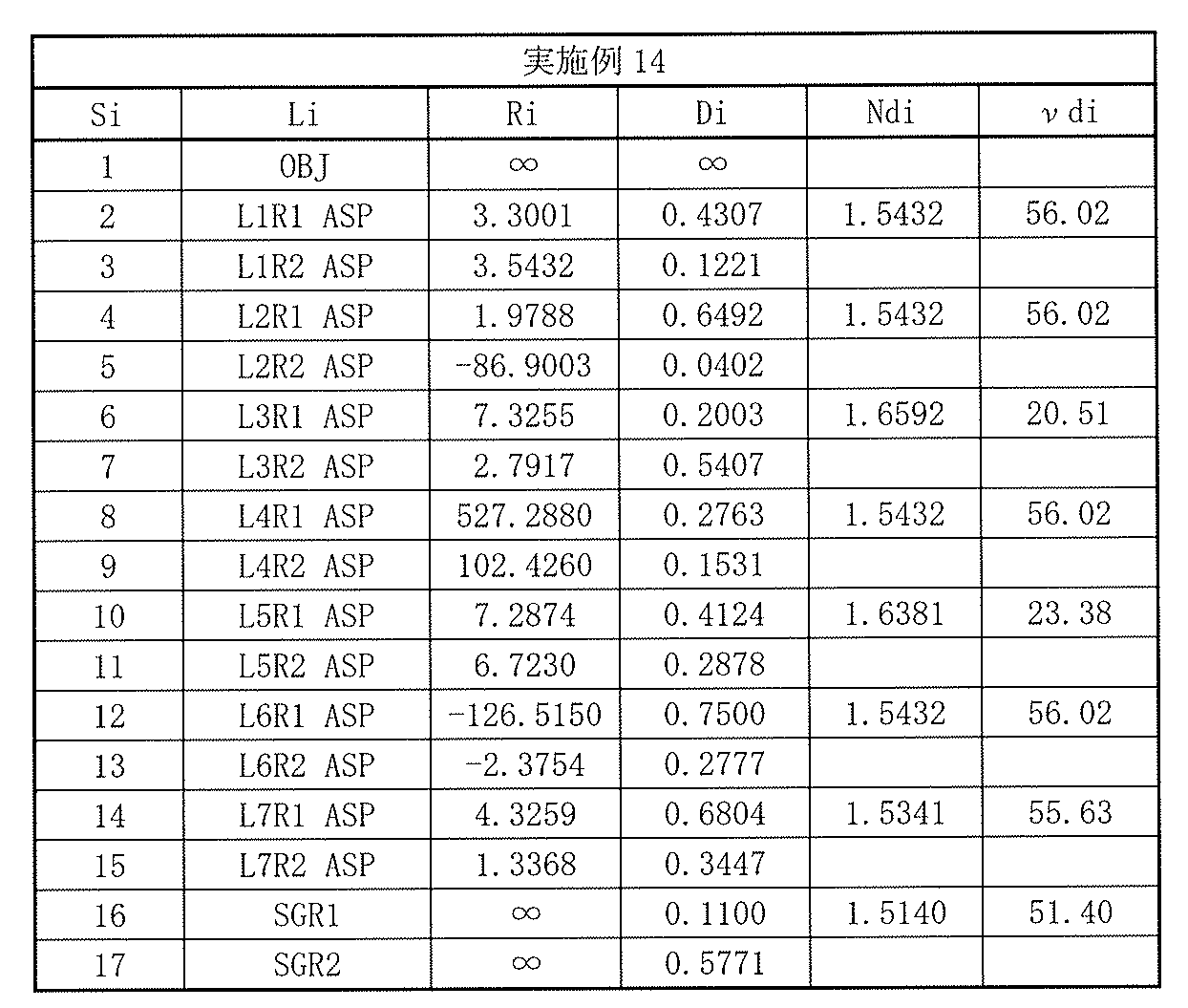
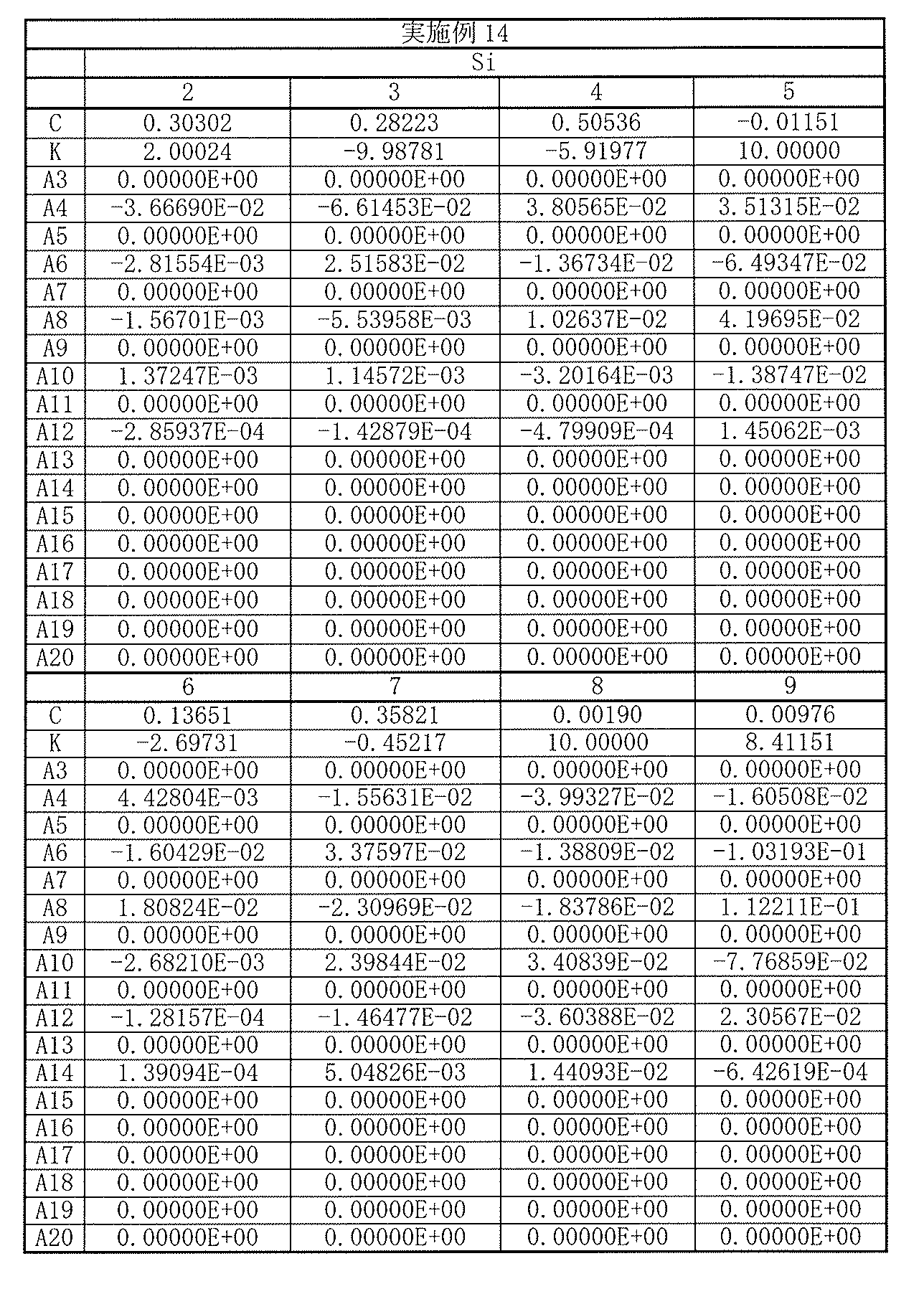

以上の数値実施例14における諸収差を図28に示す。各収差図から分かるように、小型でありながらも諸収差が良好に補正され、優れた光学性能を有していることは明らかである。
Various aberrations in the above numerical example 14 are shown in FIG. As can be seen from the respective aberration diagrams, it is clear that various aberrations are corrected well and the optical performance is excellent although it is small.
[数値実施例15]
[表43]に、図29に示した撮像レンズ15に具体的な数値を適用した数値実施例15の基本的なレンズデータを示す。 [Numerical Example 15]
[Table 43] shows basic lens data of Numerical Example 15 in which specific numerical values are applied to theimaging lens 15 shown in FIG.
[表43]に、図29に示した撮像レンズ15に具体的な数値を適用した数値実施例15の基本的なレンズデータを示す。 [Numerical Example 15]
[Table 43] shows basic lens data of Numerical Example 15 in which specific numerical values are applied to the
数値実施例15に係る撮像レンズ15において、第1レンズL1~第7レンズL7の各レンズの両面は非球面形状となっている。[表44],[表45]には、それらの非球面の形状を表す係数の値を示す。
In the imaging lens 15 according to Numerical Example 15, both surfaces of each of the first lens L1 to the seventh lens L7 are aspherical. [Table 44] and [Table 45] show coefficient values representing the shape of the aspheric surfaces.
数値実施例15に係る撮像レンズ15では、第1レンズL1は、光軸近傍において正の屈折力を有している。第2レンズL2は、光軸近傍において正の屈折力を有している。第3レンズL3は、光軸近傍において負の屈折力を有している。第4レンズL4は、光軸近傍において正の屈折力を有している。第5レンズL5は、光軸近傍において負の屈折力を有している。第6レンズL6は、光軸近傍において正の屈折力を有している。第7レンズL7は、光軸近傍において負の屈折力を有している。
In the imaging lens 15 according to Numerical Example 15, the first lens L1 has a positive refractive power in the vicinity of the optical axis. The second lens L2 has a positive refractive power in the vicinity of the optical axis. The third lens L3 has a negative refractive power in the vicinity of the optical axis. The fourth lens L4 has a positive refractive power in the vicinity of the optical axis. The fifth lens L5 has a negative refractive power in the vicinity of the optical axis. The sixth lens L6 has a positive refractive power in the vicinity of the optical axis. The seventh lens L7 has a negative refractive power in the vicinity of the optical axis.

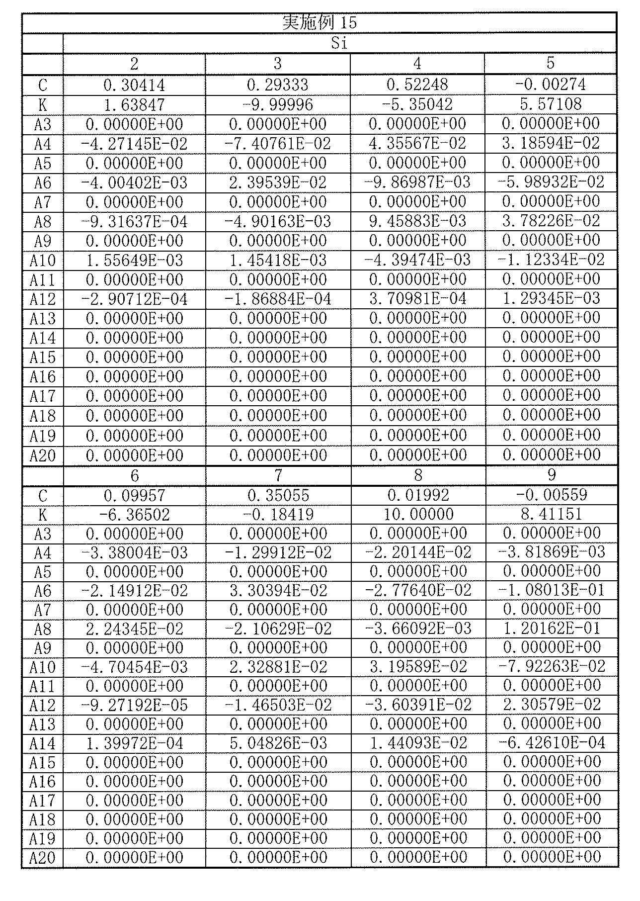

以上の数値実施例15における諸収差を図30に示す。各収差図から分かるように、小型でありながらも諸収差が良好に補正され、優れた光学性能を有していることは明らかである。
Various aberrations in the above numerical example 15 are shown in FIG. As can be seen from the respective aberration diagrams, it is clear that various aberrations are corrected well and the optical performance is excellent although it is small.
[数値実施例16]
[表46]に、図31に示した撮像レンズ16に具体的な数値を適用した数値実施例16の基本的なレンズデータを示す。 [Numerical Example 16]
Table 46 shows basic lens data of Numerical Example 16 in which specific numerical values are applied to theimaging lens 16 shown in FIG.
[表46]に、図31に示した撮像レンズ16に具体的な数値を適用した数値実施例16の基本的なレンズデータを示す。 [Numerical Example 16]
Table 46 shows basic lens data of Numerical Example 16 in which specific numerical values are applied to the
数値実施例16に係る撮像レンズ16において、第1レンズL1~第7レンズL7の各レンズの両面は非球面形状となっている。[表47],[表48]には、それらの非球面の形状を表す係数の値を示す。
In the imaging lens 16 according to Numerical Example 16, both surfaces of each of the first lens L1 to the seventh lens L7 are aspherical. [Table 47] and [Table 48] show coefficient values representing the shape of the aspheric surfaces.
数値実施例16に係る撮像レンズ16では、第1レンズL1は、光軸近傍において正の屈折力を有している。第2レンズL2は、光軸近傍において正の屈折力を有している。第3レンズL3は、光軸近傍において負の屈折力を有している。第4レンズL4は、光軸近傍において負の屈折力を有している。第5レンズL5は、光軸近傍において負の屈折力を有している。第6レンズL6は、光軸近傍において正の屈折力を有している。第7レンズL7は、光軸近傍において負の屈折力を有している。
In the imaging lens 16 according to Numerical Example 16, the first lens L1 has a positive refractive power in the vicinity of the optical axis. The second lens L2 has a positive refractive power in the vicinity of the optical axis. The third lens L3 has a negative refractive power in the vicinity of the optical axis. The fourth lens L4 has a negative refractive power in the vicinity of the optical axis. The fifth lens L5 has a negative refractive power in the vicinity of the optical axis. The sixth lens L6 has a positive refractive power in the vicinity of the optical axis. The seventh lens L7 has a negative refractive power in the vicinity of the optical axis.
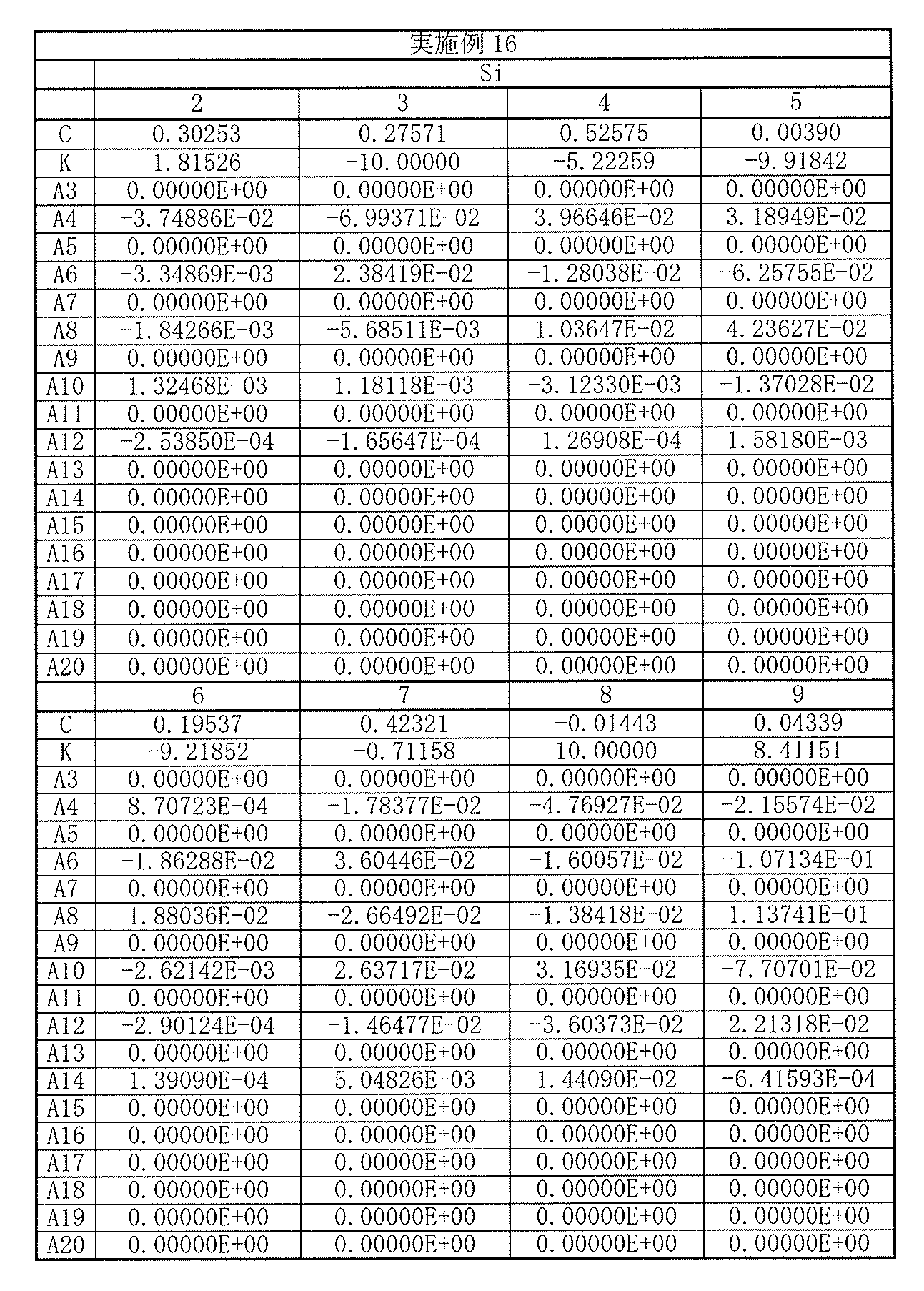
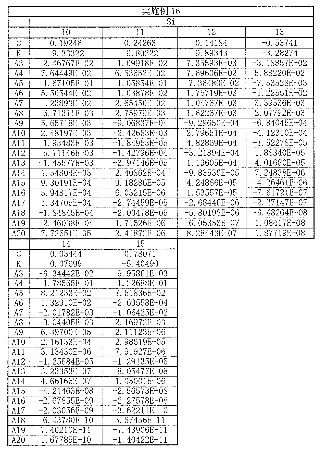
以上の数値実施例16における諸収差を図32に示す。各収差図から分かるように、小型でありながらも諸収差が良好に補正され、優れた光学性能を有していることは明らかである。
Various aberrations in the above numerical example 16 are shown in FIG. As can be seen from the respective aberration diagrams, it is clear that various aberrations are corrected well and the optical performance is excellent although it is small.
[数値実施例17]
[表49]に、図33に示した撮像レンズ17に具体的な数値を適用した数値実施例17の基本的なレンズデータを示す。 [Numerical Example 17]
Table 49 shows basic lens data of Numerical Example 17 in which specific numerical values are applied to theimaging lens 17 shown in FIG.
[表49]に、図33に示した撮像レンズ17に具体的な数値を適用した数値実施例17の基本的なレンズデータを示す。 [Numerical Example 17]
Table 49 shows basic lens data of Numerical Example 17 in which specific numerical values are applied to the
数値実施例17に係る撮像レンズ17において、第1レンズL1~第7レンズL7の各レンズの両面は非球面形状となっている。[表50],[表51]には、それらの非球面の形状を表す係数の値を示す。
In the imaging lens 17 according to Numerical Example 17, both surfaces of each of the first lens L1 to the seventh lens L7 are aspherical. [Table 50] and [Table 51] show values of coefficients representing the shape of the aspheric surfaces.
数値実施例17に係る撮像レンズ17では、第1レンズL1は、光軸近傍において正の屈折力を有している。第2レンズL2は、光軸近傍において正の屈折力を有している。第3レンズL3は、光軸近傍において負の屈折力を有している。第4レンズL4は、光軸近傍において正の屈折力を有している。第5レンズL5は、光軸近傍において負の屈折力を有している。第6レンズL6は、光軸近傍において正の屈折力を有している。第7レンズL7は、光軸近傍において負の屈折力を有している。
In the imaging lens 17 according to Numerical Example 17, the first lens L1 has a positive refractive power in the vicinity of the optical axis. The second lens L2 has a positive refractive power in the vicinity of the optical axis. The third lens L3 has a negative refractive power in the vicinity of the optical axis. The fourth lens L4 has a positive refractive power in the vicinity of the optical axis. The fifth lens L5 has a negative refractive power in the vicinity of the optical axis. The sixth lens L6 has a positive refractive power in the vicinity of the optical axis. The seventh lens L7 has a negative refractive power in the vicinity of the optical axis.

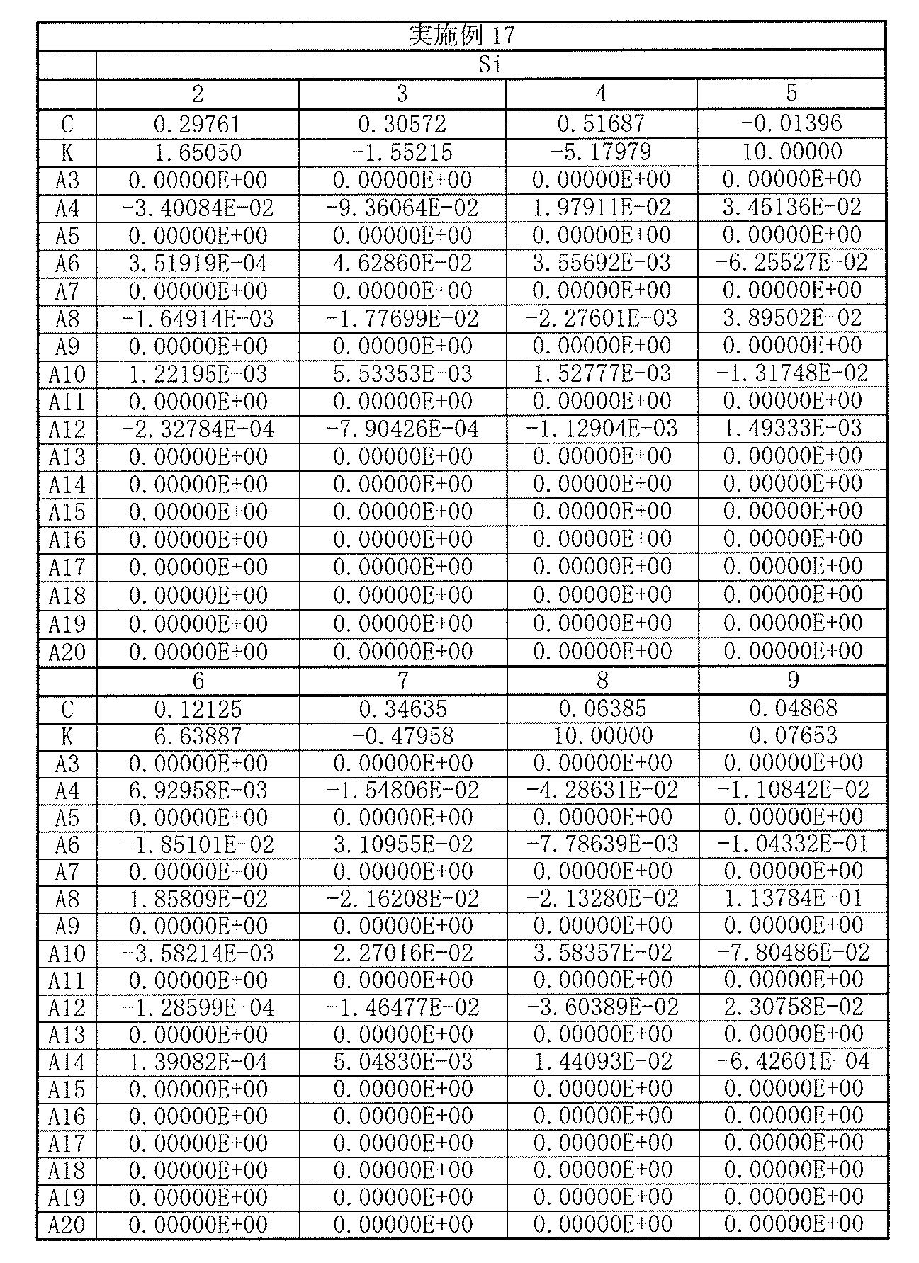

以上の数値実施例17における諸収差を図34に示す。各収差図から分かるように、小型でありながらも諸収差が良好に補正され、優れた光学性能を有していることは明らかである。
The various aberrations in the above numerical example 17 are shown in FIG. As can be seen from the respective aberration diagrams, it is clear that various aberrations are corrected well and the optical performance is excellent although it is small.
[数値実施例18]
[表52]に、図35に示した撮像レンズ18に具体的な数値を適用した数値実施例18の基本的なレンズデータを示す。 [Numerical Example 18]
[Table 52] shows basic lens data of Numerical Example 18 in which specific numerical values are applied to theimaging lens 18 shown in FIG.
[表52]に、図35に示した撮像レンズ18に具体的な数値を適用した数値実施例18の基本的なレンズデータを示す。 [Numerical Example 18]
[Table 52] shows basic lens data of Numerical Example 18 in which specific numerical values are applied to the
数値実施例18に係る撮像レンズ18において、第1レンズL1~第7レンズL7の各レンズの両面は非球面形状となっている。[表53],[表54]には、それらの非球面の形状を表す係数の値を示す。
In the imaging lens 18 according to Numerical Example 18, both surfaces of each of the first lens L1 to the seventh lens L7 are aspherical. [Table 53] and [Table 54] show coefficient values representing the shape of the aspheric surfaces.
数値実施例18に係る撮像レンズ18では、第1レンズL1は、光軸近傍において正の屈折力を有している。第2レンズL2は、光軸近傍において正の屈折力を有している。第3レンズL3は、光軸近傍において負の屈折力を有している。第4レンズL4は、光軸近傍において正の屈折力を有している。第5レンズL5は、光軸近傍において負の屈折力を有している。第6レンズL6は、光軸近傍において正の屈折力を有している。第7レンズL7は、光軸近傍において負の屈折力を有している。
In the imaging lens 18 according to Numerical Example 18, the first lens L1 has a positive refractive power in the vicinity of the optical axis. The second lens L2 has a positive refractive power in the vicinity of the optical axis. The third lens L3 has a negative refractive power in the vicinity of the optical axis. The fourth lens L4 has a positive refractive power in the vicinity of the optical axis. The fifth lens L5 has a negative refractive power in the vicinity of the optical axis. The sixth lens L6 has a positive refractive power in the vicinity of the optical axis. The seventh lens L7 has a negative refractive power in the vicinity of the optical axis.
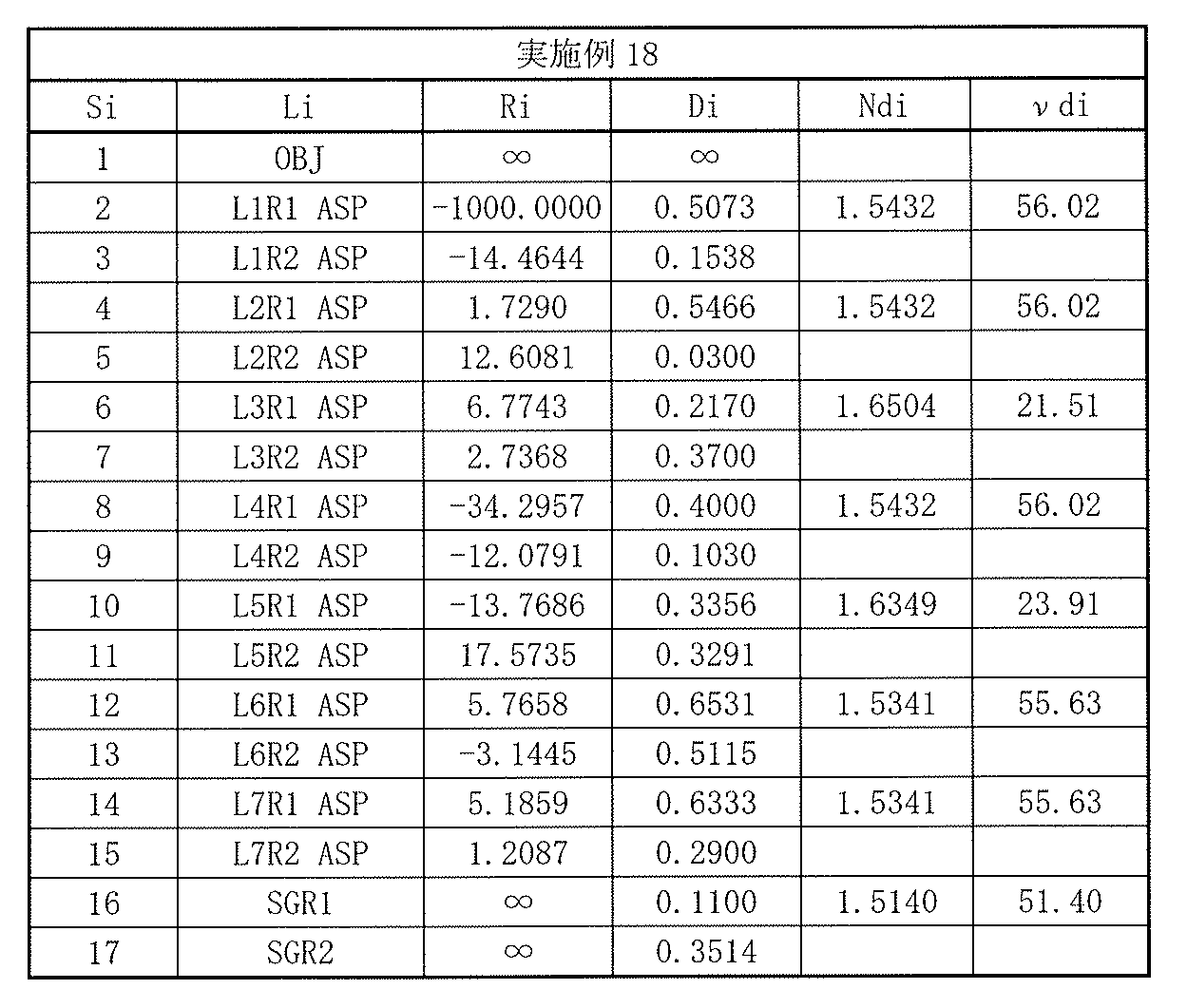


以上の数値実施例18における諸収差を図36に示す。各収差図から分かるように、小型でありながらも諸収差が良好に補正され、優れた光学性能を有していることは明らかである。
Various aberrations in the above numerical example 18 are shown in FIG. As can be seen from the respective aberration diagrams, it is clear that various aberrations are corrected well and the optical performance is excellent although it is small.
[数値実施例19]
[表55]に、図37に示した撮像レンズ19に具体的な数値を適用した数値実施例19の基本的なレンズデータを示す。 [Numerical Example 19]
Table 55 shows basic lens data of Numerical Example 19 in which specific numerical values are applied to theimaging lens 19 shown in FIG.
[表55]に、図37に示した撮像レンズ19に具体的な数値を適用した数値実施例19の基本的なレンズデータを示す。 [Numerical Example 19]
Table 55 shows basic lens data of Numerical Example 19 in which specific numerical values are applied to the
数値実施例19に係る撮像レンズ19において、第1レンズL1~第7レンズL7の各レンズの両面は非球面形状となっている。[表56],[表57]には、それらの非球面の形状を表す係数の値を示す。
In the imaging lens 19 according to Numerical Example 19, both surfaces of each of the first lens L1 to the seventh lens L7 are aspheric. [Table 56] and [Table 57] show coefficient values representing the shape of the aspheric surfaces.
数値実施例19に係る撮像レンズ19では、第1レンズL1は、光軸近傍において正の屈折力を有している。第2レンズL2は、光軸近傍において正の屈折力を有している。第3レンズL3は、光軸近傍において負の屈折力を有している。第4レンズL4は、光軸近傍において負の屈折力を有している。第5レンズL5は、光軸近傍において負の屈折力を有している。第6レンズL6は、光軸近傍において正の屈折力を有している。第7レンズL7は、光軸近傍において負の屈折力を有している。
In the imaging lens 19 according to Numerical Example 19, the first lens L1 has a positive refractive power in the vicinity of the optical axis. The second lens L2 has a positive refractive power in the vicinity of the optical axis. The third lens L3 has a negative refractive power in the vicinity of the optical axis. The fourth lens L4 has a negative refractive power in the vicinity of the optical axis. The fifth lens L5 has a negative refractive power in the vicinity of the optical axis. The sixth lens L6 has a positive refractive power in the vicinity of the optical axis. The seventh lens L7 has a negative refractive power in the vicinity of the optical axis.
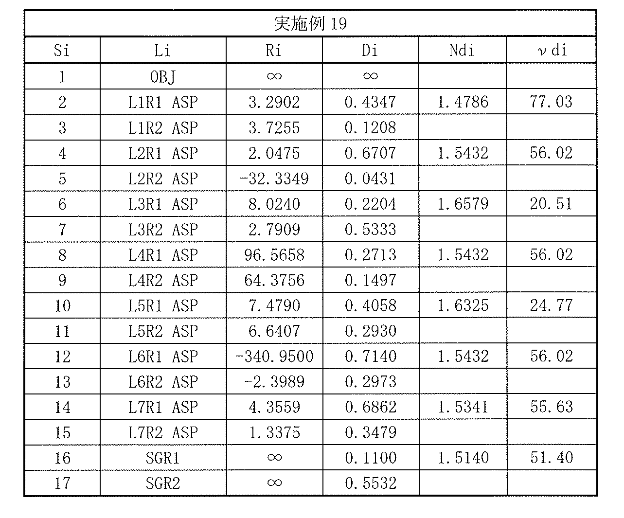
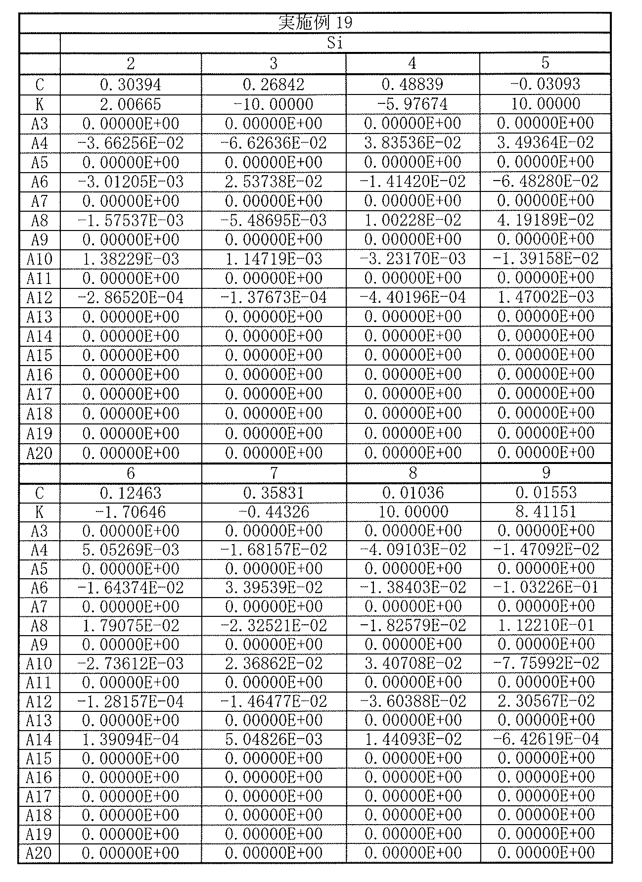

以上の数値実施例19における諸収差を図38に示す。各収差図から分かるように、小型でありながらも諸収差が良好に補正され、優れた光学性能を有していることは明らかである。
The various aberrations in the above numerical example 19 are shown in FIG. As can be seen from the respective aberration diagrams, it is clear that various aberrations are corrected well and the optical performance is excellent although it is small.
[各実施例のその他の数値データ]
[表58]には、レンズ全系の焦点距離f、F値、および半画角ωと、第1レンズL1、第2レンズL2、第3レンズL3、第4レンズL4、第5レンズL5、第6レンズL6、および第7レンズL7のそれぞの焦点距離f1,f2,f3,f4,f5,f6,f7との値を、各数値実施例についてまとめたものを示す。 [Other numerical data of each example]
In [Table 58], the focal length f, F value, and half angle of view ω of the entire lens system, the first lens L1, the second lens L2, the third lens L3, the fourth lens L4, the fifth lens L5, The values of the focal lengths f1, f2, f3, f4, f5, f6, and f7 of the sixth lens L6 and the seventh lens L7 are summarized for each numerical example.
また、[表59]および[表60]、には、上述の各条件式に関する値を、各数値実施例についてまとめたものを示す。なお、実施例18については、条件式(2)の範囲外となっている。
Also, [Table 59] and [Table 60] show values relating to the above-described conditional expressions, which are summarized for each numerical example. Note that Example 18 is out of the range of conditional expression (2).
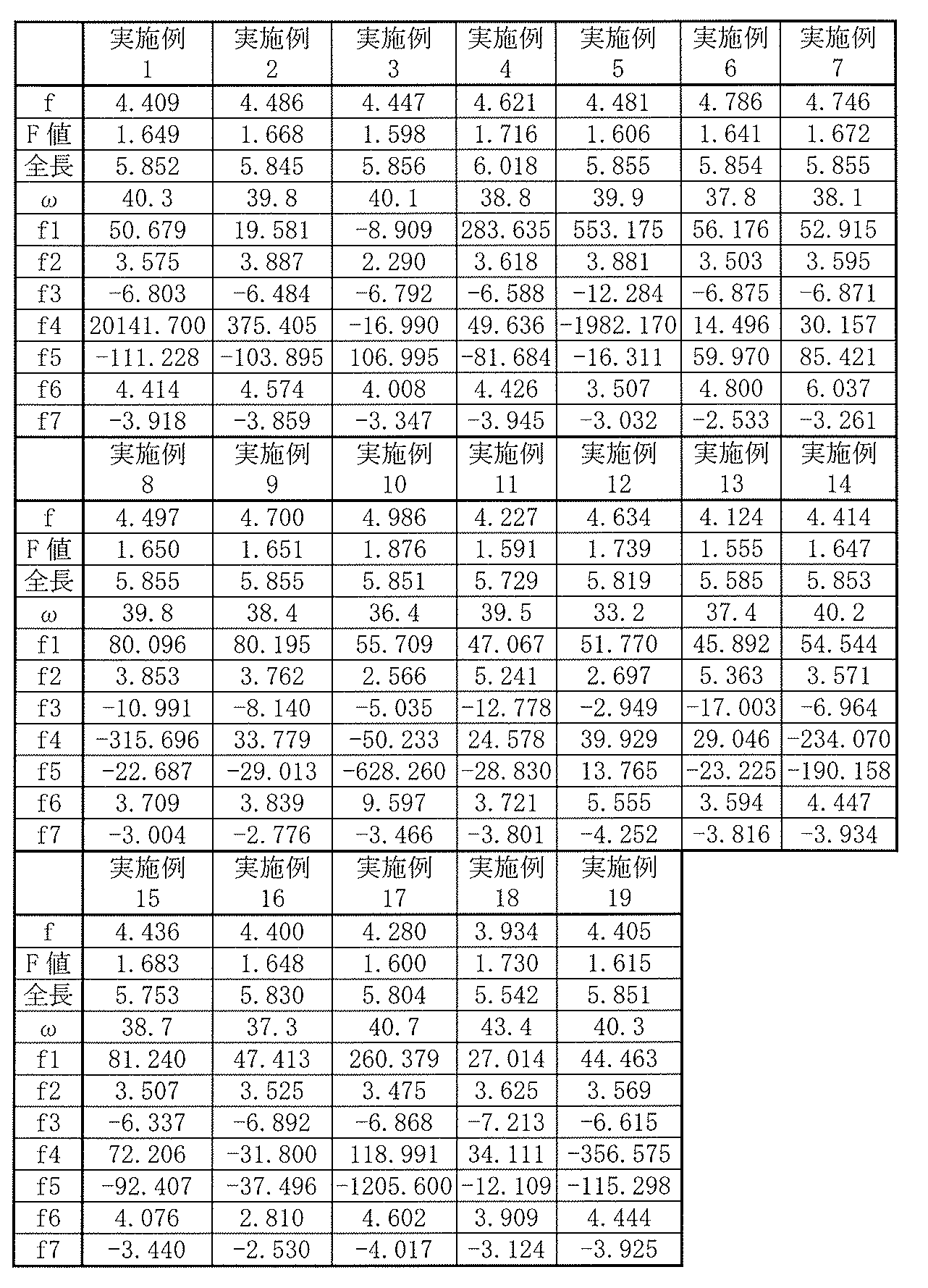
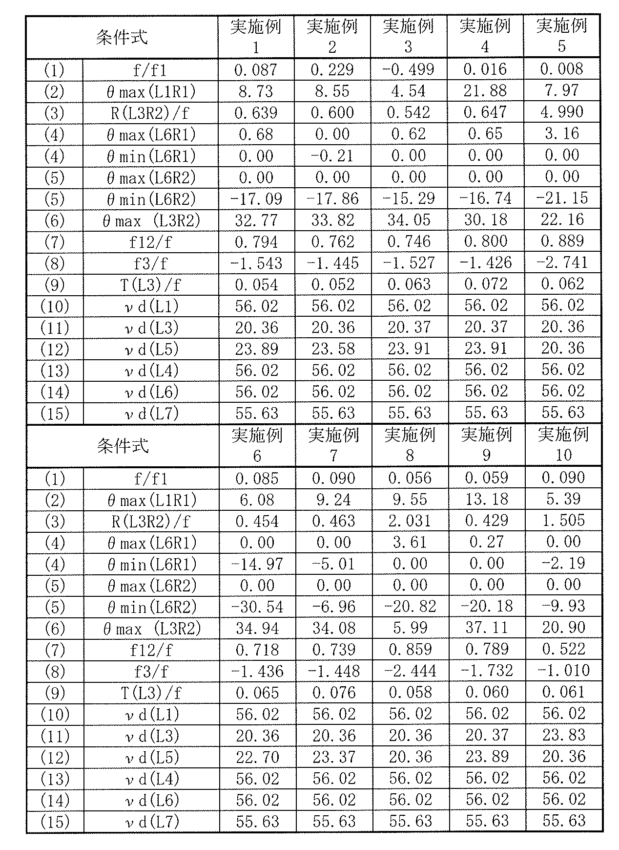
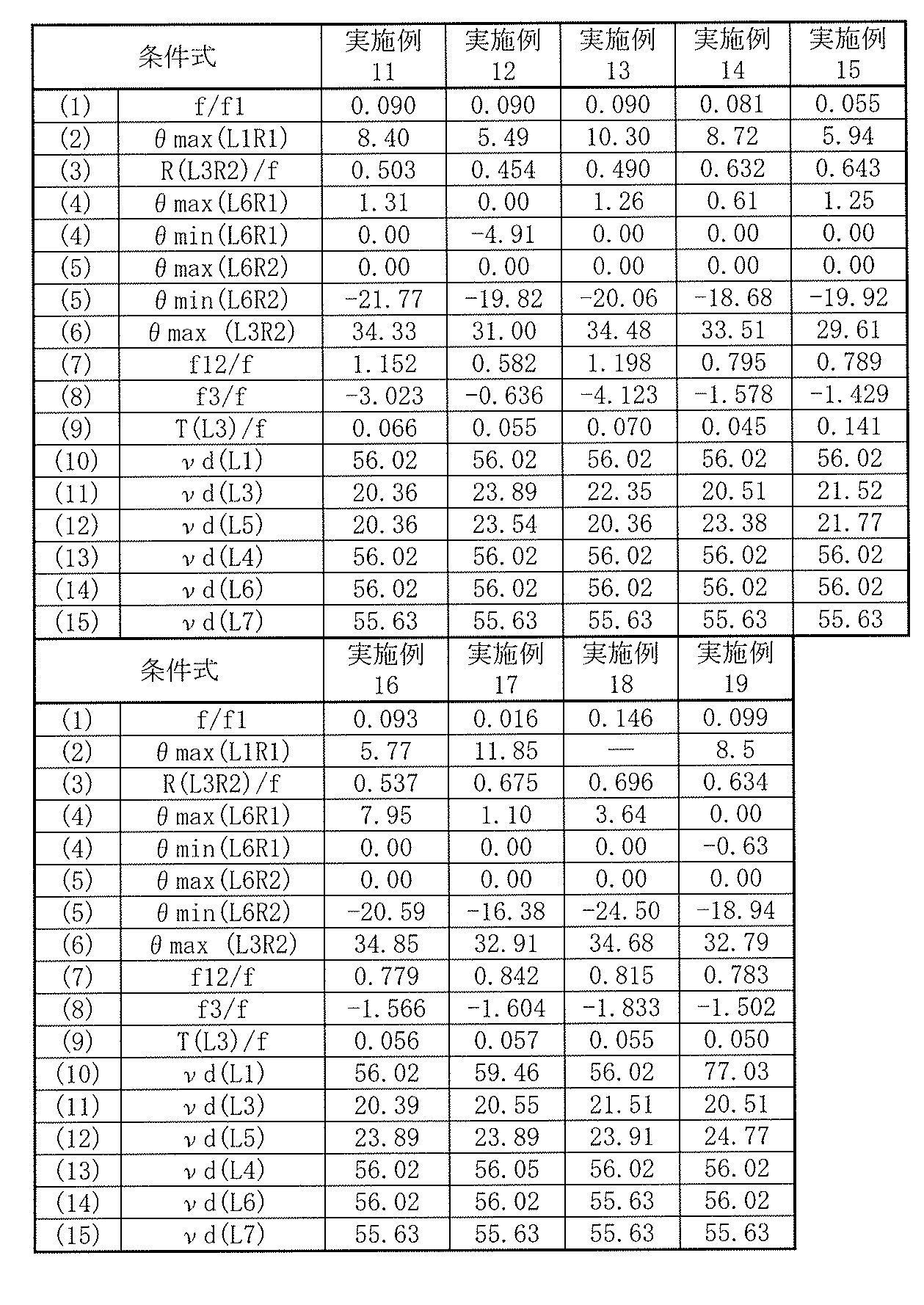
<5.その他の実施の形態>
本開示による技術は、上記実施の形態および実施例の説明に限定されず種々の変形実施が可能である。
例えば、上記各数値実施例において示した各部の形状および数値は、いずれも本技術を実施するための具体化のほんの一例に過ぎず、これらによって本技術の技術的範囲が限定的に解釈されることがあってはならないものである。 <5. Other Embodiments>
The technology according to the present disclosure is not limited to the description of the above-described embodiments and examples, and various modifications can be made.
For example, the shapes and numerical values of the respective parts shown in the numerical examples are merely examples of embodiments for carrying out the present technology, and the technical scope of the present technology is interpreted in a limited manner by these. There should be no such thing.
また、上記実施の形態および実施例では、実質的に7枚のレンズからなる構成について説明したが、実質的に屈折力を有さないレンズをさらに備えた構成であってもよい。
In the above-described embodiments and examples, the configuration including substantially seven lenses has been described. However, the configuration may further include a lens having substantially no refractive power.
また例えば、本技術は以下のような構成を取ることができる。
[1]
物体側から像面側に向かって順に、
光軸近傍の形状が物体側に凸面を向けたメニスカス形状の第1レンズと、
光軸近傍において物体側に凸面を向けた正の屈折力を有する第2レンズと、
光軸近傍において負の屈折力を有する第3レンズと、
第4レンズと、
第5レンズと、
光軸近傍において正の屈折力を有する第6レンズと、
光軸近傍において負の屈折力を有し、像面側のレンズ面が変曲点を有する非球面形状とされた第7レンズと
から構成されている
撮像レンズ。
[2]
以下の条件式を満足する
上記[1]に記載の撮像レンズ。
-0.5<f/f1<0.23 ……(1)
ただし、
f:レンズ全系の焦点距離
f1:前記第1レンズの焦点距離
とする。
[3]
以下の条件式を満足する
上記[1]または[2]に記載の撮像レンズ。
0<θmax(L1R1)<25 ……(2)
0.3<R(L3R2)/f<5 ……(3)
ただし、
θmax(L1R1):有効径内における前記第1レンズの物体側のレンズ面の面角度の最大値(レンズ面が像面側に傾く場合を正とし、単位は「度」)
R(L3R2):前記第3レンズの像面側のレンズ面の曲率半径
f:レンズ全系の焦点距離
とする。
[4]
以下の条件式を満足する
上記[1]ないし[3]のいずれか1つに記載の撮像レンズ。
-15<θmin(L6R1)<θmax(L6R1)<8 ……(4)
-31<θmin(L6R2)<θmax(L6R2)<-5 ……(5)
ただし、
θmax(L6R1):有効径の3割の径内における前記第6レンズの物体側のレンズ面の面角度の最大値(レンズ面が像面側に傾く場合を正とし、単位は「度」)
θmin(L6R1):有効径の3割の径内における前記第6レンズの物体側のレンズ面の面角度の最小値(レンズ面が像面側に傾く場合を正とし、単位は「度」)
θmax(L6R2):有効径の7割の径内における前記第6レンズの像面側のレンズ面の面角度の最大値(レンズ面が像面側に傾く場合を正とし、単位は「度」)
θmin(L6R2):有効径の7割の径内における前記第6レンズの像面側のレンズ面の面角度の最小値(レンズ面が像面側に傾く場合を正とし、単位は「度」)
とする。
[5]
以下の条件式を満足する
上記[1]ないし[4]のいずれか1つに記載の撮像レンズ。
5<θmax(L3R2)<40 ……(6)
ただし、
θmax(L3R2):有効径内における前記第3レンズの像面側のレンズ面の面角度の最大値(レンズ面が像面側に傾く場合を正とし、単位は「度」)
とする。
[6]
以下の条件式を満足する
上記[1]ないし[5]のいずれか1つに記載の撮像レンズ。
0.3<f12/f<2.0 ……(7)
ただし、
f:レンズ全系の焦点距離
f12:前記第1レンズと前記第2レンズとの合成焦点距離
とする。
[7]
以下の条件式を満足する
上記[1]ないし[6]のいずれか1つに記載の撮像レンズ。
-5<f3/f<-0.5 ……(8)
ただし、
f:レンズ全系の焦点距離
f3:前記第3レンズの焦点距離
とする。
[8]
以下の条件式を満足する
上記[1]ないし[7]のいずれか1つに記載の撮像レンズ。
0.023<T(L3)/f<0.15 ……(9)
ただし、
f:レンズ全系の焦点距離
T(L3):前記第3レンズの中心厚
とする。
[9]
以下の条件式を満足する
上記[1]ないし[9]のいずれか1つに記載の撮像レンズ。
νd(L1)>50 ……(10)
ただし、
νd(L1):前記第1レンズのd線に対するアッベ数
とする。
[10]
以下の条件式を満足する
上記[1]ないし[10]のいずれか1つに記載の撮像レンズ。
νd(L3)<35 ……(11)
νd(L5)<35 ……(12)
ただし、
νd(L3):前記第3レンズのd線に対するアッベ数
νd(L5):前記第5レンズのd線に対するアッベ数
とする。
[11]
以下の条件式を満足する
上記[1]ないし[11]のいずれか1つに記載の撮像レンズ。
νd(L4)>50 ……(13)
νd(L6)>50 ……(14)
νd(L7)>50 ……(15)
ただし、
νd(L4):前記第4レンズのd線に対するアッベ数
νd(L6):前記第6レンズのd線に対するアッベ数
νd(L7):前記第7レンズのd線に対するアッベ数
とする。
[12]
物体側から像面側に向かって順に、
第1レンズと、
光軸近傍において正の屈折力を有する第2レンズと、
光軸近傍において負の屈折力を有する第3レンズと、
第4レンズと、
第5レンズと、
光軸近傍において正の屈折力を有する第6レンズと、
光軸近傍において負の屈折力を有し、像面側のレンズ面が変曲点を有する非球面形状とされた第7レンズと
から構成され、以下の条件式を満足する
撮像レンズ。
-0.5<f/f1<0.23 ……(1)
ただし、
f:レンズ全系の焦点距離
f1:前記第1レンズの焦点距離
とする。
[13]
以下の条件式を満足する
上記[12]に記載の撮像レンズ。
0.3<R(L3R2)/f<5 ……(3)
ただし、
R(L3R2):前記第3レンズの像面側のレンズ面の曲率半径
f:レンズ全系の焦点距離
とする。
[14]
以下の条件式を満足する
上記[12]または[13]に記載の撮像レンズ。
-15<θmin(L6R1)<θmax(L6R1)<8 ……(4)
-31<θmin(L6R2)<θmax(L6R2)<-5 ……(5)
ただし、
θmax(L6R1):有効径の3割の径内における前記第6レンズの物体側のレンズ面の面角度の最大値(レンズ面が像面側に傾く場合を正とし、単位は「度」)
θmin(L6R1):有効径の3割の径内における前記第6レンズの物体側のレンズ面の面角度の最小値(レンズ面が像面側に傾く場合を正とし、単位は「度」)
θmax(L6R2):有効径の7割の径内における前記第6レンズの像面側のレンズ面の面角度の最大値(レンズ面が像面側に傾く場合を正とし、単位は「度」)
θmin(L6R2):有効径の7割の径内における前記第6レンズの像面側のレンズ面の面角度の最小値(レンズ面が像面側に傾く場合を正とし、単位は「度」)
とする。
[15]
以下の条件式を満足する
上記[12]ないし[14]のいずれか1つに記載の撮像レンズ。
5<θmax(L3R2)<40 ……(6)
ただし、
θmax(L3R2):有効径内における前記第3レンズの像面側のレンズ面の面角度の最大値(レンズ面が像面側に傾く場合を正とし、単位は「度」)
とする。
[16]
以下の条件式を満足する
上記[12]ないし[15]のいずれか1つに記載の撮像レンズ。
0.3<f12/f<2.0 ……(7)
ただし、
f:レンズ全系の焦点距離
f12:前記第1レンズと前記第2レンズとの合成焦点距離
とする。
[17]
以下の条件式を満足する
上記[12]ないし[16]のいずれか1つに記載の撮像レンズ。
-5<f3/f<-0.5 ……(8)
ただし、
f:レンズ全系の焦点距離
f3:前記第3レンズの焦点距離
とする。
[18]
以下の条件式を満足する
上記[12]ないし[17]のいずれか1つに記載の撮像レンズ。
0.023<T(L3)/f<0.15 ……(9)
ただし、
f:レンズ全系の焦点距離
T(L3):前記第3レンズの中心厚
とする。
[19]
実質的に屈折力を有さないレンズをさらに備えた
上記[1]ないし[18]のいずれか1つに記載の撮像レンズ。
[20]
撮像レンズと、前記撮像レンズによって形成された光学像に応じた撮像信号を出力する撮像素子とを含み、
前記撮像レンズは、
物体側から像面側に向かって順に、
光軸近傍の形状が物体側に凸面を向けたメニスカス形状の第1レンズと、
光軸近傍において物体側に凸面を向けた正の屈折力を有する第2レンズと、
光軸近傍において負の屈折力を有する第3レンズと、
第4レンズと、
第5レンズと、
光軸近傍において正の屈折力を有する第6レンズと、
光軸近傍において負の屈折力を有し、像面側のレンズ面が変曲点を有する非球面形状とされた第7レンズと
から構成されている
撮像装置。
[21]
撮像レンズと、前記撮像レンズによって形成された光学像に応じた撮像信号を出力する撮像素子とを含み、
前記撮像レンズは、
物体側から像面側に向かって順に、
第1レンズと、
光軸近傍において正の屈折力を有する第2レンズと、
光軸近傍において負の屈折力を有する第3レンズと、
第4レンズと、
第5レンズと、
光軸近傍において正の屈折力を有する第6レンズと、
光軸近傍において負の屈折力を有し、像面側のレンズ面が変曲点を有する非球面形状とされた第7レンズと
から構成され、以下の条件式を満足する
撮像装置。
-0.5<f/f1<0.23 ……(1)
ただし、
f:レンズ全系の焦点距離
f1:前記第1レンズの焦点距離
とする。
[22]
前記撮像レンズは、実質的に屈折力を有さないレンズをさらに備える
上記[20]または[21]に記載の撮像装置。 For example, this technique can take the following composition.
[1]
In order from the object side to the image plane side,
A first lens having a meniscus shape in which the shape near the optical axis has a convex surface facing the object side;
A second lens having a positive refractive power with a convex surface facing the object side in the vicinity of the optical axis;
A third lens having negative refractive power in the vicinity of the optical axis;
A fourth lens;
A fifth lens;
A sixth lens having a positive refractive power in the vicinity of the optical axis;
An imaging lens comprising: a seventh lens having a negative refractive power in the vicinity of the optical axis and having an aspherical shape with an inflection point on the lens surface on the image plane side.
[2]
The imaging lens according to [1], wherein the following conditional expression is satisfied.
-0.5 <f / f1 <0.23 (1)
However,
f: focal length of the entire lens system f1: a focal length of the first lens.
[3]
The imaging lens according to [1] or [2], wherein the following conditional expression is satisfied.
0 <θmax (L1R1) <25 (2)
0.3 <R (L3R2) / f <5 (3)
However,
θmax (L1R1): Maximum value of the surface angle of the object side lens surface of the first lens within the effective diameter (positive when the lens surface is tilted toward the image surface side, the unit is “degree”)
R (L3R2): radius of curvature of the lens surface on the image plane side of the third lens f: the focal length of the entire lens system.
[4]
The imaging lens according to any one of [1] to [3], wherein the following conditional expression is satisfied.
−15 <θmin (L6R1) <θmax (L6R1) <8 (4)
−31 <θmin (L6R2) <θmax (L6R2) <− 5 (5)
However,
θmax (L6R1): Maximum value of the surface angle of the object side lens surface of the sixth lens within 30% of the effective diameter (positive when the lens surface is tilted to the image surface side, the unit is “degree”)
θmin (L6R1): Minimum value of the surface angle of the object side lens surface of the sixth lens within 30% of the effective diameter (positive when the lens surface is tilted toward the image surface side, the unit is “degrees”)
θmax (L6R2): the maximum value of the surface angle of the sixth lens surface on the image surface side within 70% of the effective diameter (positive when the lens surface is inclined toward the image surface side, the unit being “degrees”) )
θmin (L6R2): Minimum value of the surface angle of the sixth lens surface on the image surface side within 70% of the effective diameter (positive when the lens surface is inclined toward the image surface side, the unit being “degrees”) )
And
[5]
The imaging lens according to any one of [1] to [4], wherein the following conditional expression is satisfied.
5 <θmax (L3R2) <40 (6)
However,
θmax (L3R2): the maximum value of the surface angle of the third lens surface on the image surface side within the effective diameter (positive when the lens surface is inclined toward the image surface side, the unit is “degree”)
And
[6]
The imaging lens according to any one of [1] to [5], wherein the following conditional expression is satisfied.
0.3 <f12 / f <2.0 (7)
However,
f: Focal length of the entire lens system f12: The combined focal length of the first lens and the second lens.
[7]
The imaging lens according to any one of [1] to [6], wherein the following conditional expression is satisfied.
−5 <f3 / f <−0.5 (8)
However,
f: focal length of the entire lens system f3: the focal length of the third lens.
[8]
The imaging lens according to any one of [1] to [7], wherein the following conditional expression is satisfied.
0.023 <T (L3) / f <0.15 (9)
However,
f: Focal length of the entire lens system T (L3): The center thickness of the third lens.
[9]
The imaging lens according to any one of [1] to [9], wherein the following conditional expression is satisfied.
νd (L1)> 50 (10)
However,
νd (L1): An Abbe number with respect to the d-line of the first lens.
[10]
The imaging lens according to any one of [1] to [10], wherein the following conditional expression is satisfied.
νd (L3) <35 (11)
νd (L5) <35 (12)
However,
νd (L3): Abbe number of the third lens with respect to the d-line νd (L5): Abbe number of the fifth lens with respect to the d-line.
[11]
The imaging lens according to any one of [1] to [11], wherein the following conditional expression is satisfied.
νd (L4)> 50 (13)
νd (L6)> 50 (14)
νd (L7)> 50 (15)
However,
νd (L4): Abbe number of the fourth lens with respect to the d-line νd (L6): Abbe number of the sixth lens with respect to the d-line νd (L7): Abbe number of the seventh lens with respect to the d-line.
[12]
In order from the object side to the image plane side,
A first lens;
A second lens having a positive refractive power in the vicinity of the optical axis;
A third lens having negative refractive power in the vicinity of the optical axis;
A fourth lens;
A fifth lens;
A sixth lens having a positive refractive power in the vicinity of the optical axis;
An imaging lens that has a negative refractive power in the vicinity of the optical axis and has an aspherical shape with an inflection point on the lens surface on the image plane side, and satisfies the following conditional expression.
-0.5 <f / f1 <0.23 (1)
However,
f: focal length of the entire lens system f1: a focal length of the first lens.
[13]
The imaging lens according to [12], wherein the following conditional expression is satisfied.
0.3 <R (L3R2) / f <5 (3)
However,
R (L3R2): radius of curvature of the lens surface on the image plane side of the third lens f: the focal length of the entire lens system.
[14]
The imaging lens according to [12] or [13], wherein the following conditional expression is satisfied.
−15 <θmin (L6R1) <θmax (L6R1) <8 (4)
−31 <θmin (L6R2) <θmax (L6R2) <− 5 (5)
However,
θmax (L6R1): Maximum value of the surface angle of the object side lens surface of the sixth lens within 30% of the effective diameter (positive when the lens surface is tilted to the image surface side, the unit is “degree”)
θmin (L6R1): Minimum value of the surface angle of the object side lens surface of the sixth lens within 30% of the effective diameter (positive when the lens surface is tilted toward the image surface side, the unit is “degrees”)
θmax (L6R2): the maximum value of the surface angle of the sixth lens surface on the image surface side within 70% of the effective diameter (positive when the lens surface is inclined toward the image surface side, the unit being “degrees”) )
θmin (L6R2): Minimum value of the surface angle of the sixth lens surface on the image surface side within 70% of the effective diameter (positive when the lens surface is inclined toward the image surface side, the unit being “degrees”) )
And
[15]
The imaging lens according to any one of [12] to [14], wherein the following conditional expression is satisfied.
5 <θmax (L3R2) <40 (6)
However,
θmax (L3R2): the maximum value of the surface angle of the third lens surface on the image surface side within the effective diameter (positive when the lens surface is inclined toward the image surface side, the unit is “degree”)
And
[16]
The imaging lens according to any one of [12] to [15], wherein the following conditional expression is satisfied.
0.3 <f12 / f <2.0 (7)
However,
f: Focal length of the entire lens system f12: The combined focal length of the first lens and the second lens.
[17]
The imaging lens according to any one of [12] to [16], wherein the following conditional expression is satisfied.
−5 <f3 / f <−0.5 (8)
However,
f: focal length of the entire lens system f3: the focal length of the third lens.
[18]
The imaging lens according to any one of [12] to [17], wherein the following conditional expression is satisfied.
0.023 <T (L3) / f <0.15 (9)
However,
f: Focal length of the entire lens system T (L3): The center thickness of the third lens.
[19]
The imaging lens according to any one of [1] to [18], further including a lens that has substantially no refractive power.
[20]
An imaging lens, and an imaging element that outputs an imaging signal corresponding to an optical image formed by the imaging lens;
The imaging lens is
In order from the object side to the image plane side,
A first lens having a meniscus shape in which the shape near the optical axis has a convex surface facing the object side;
A second lens having a positive refractive power with a convex surface facing the object side in the vicinity of the optical axis;
A third lens having negative refractive power in the vicinity of the optical axis;
A fourth lens;
A fifth lens;
A sixth lens having a positive refractive power in the vicinity of the optical axis;
An imaging apparatus comprising: a seventh lens having a negative refractive power in the vicinity of the optical axis and having an aspherical shape with an inflection point on the lens surface on the image plane side.
[21]
An imaging lens, and an imaging element that outputs an imaging signal corresponding to an optical image formed by the imaging lens;
The imaging lens is
In order from the object side to the image plane side,
A first lens;
A second lens having a positive refractive power in the vicinity of the optical axis;
A third lens having negative refractive power in the vicinity of the optical axis;
A fourth lens;
A fifth lens;
A sixth lens having a positive refractive power in the vicinity of the optical axis;
An imaging device that includes a seventh lens having a negative refractive power in the vicinity of the optical axis and an aspherical surface having an inflection point on the lens surface on the image plane side, and satisfies the following conditional expression.
-0.5 <f / f1 <0.23 (1)
However,
f: focal length of the entire lens system f1: a focal length of the first lens.
[22]
The imaging device according to [20] or [21], wherein the imaging lens further includes a lens having substantially no refractive power.
[1]
物体側から像面側に向かって順に、
光軸近傍の形状が物体側に凸面を向けたメニスカス形状の第1レンズと、
光軸近傍において物体側に凸面を向けた正の屈折力を有する第2レンズと、
光軸近傍において負の屈折力を有する第3レンズと、
第4レンズと、
第5レンズと、
光軸近傍において正の屈折力を有する第6レンズと、
光軸近傍において負の屈折力を有し、像面側のレンズ面が変曲点を有する非球面形状とされた第7レンズと
から構成されている
撮像レンズ。
[2]
以下の条件式を満足する
上記[1]に記載の撮像レンズ。
-0.5<f/f1<0.23 ……(1)
ただし、
f:レンズ全系の焦点距離
f1:前記第1レンズの焦点距離
とする。
[3]
以下の条件式を満足する
上記[1]または[2]に記載の撮像レンズ。
0<θmax(L1R1)<25 ……(2)
0.3<R(L3R2)/f<5 ……(3)
ただし、
θmax(L1R1):有効径内における前記第1レンズの物体側のレンズ面の面角度の最大値(レンズ面が像面側に傾く場合を正とし、単位は「度」)
R(L3R2):前記第3レンズの像面側のレンズ面の曲率半径
f:レンズ全系の焦点距離
とする。
[4]
以下の条件式を満足する
上記[1]ないし[3]のいずれか1つに記載の撮像レンズ。
-15<θmin(L6R1)<θmax(L6R1)<8 ……(4)
-31<θmin(L6R2)<θmax(L6R2)<-5 ……(5)
ただし、
θmax(L6R1):有効径の3割の径内における前記第6レンズの物体側のレンズ面の面角度の最大値(レンズ面が像面側に傾く場合を正とし、単位は「度」)
θmin(L6R1):有効径の3割の径内における前記第6レンズの物体側のレンズ面の面角度の最小値(レンズ面が像面側に傾く場合を正とし、単位は「度」)
θmax(L6R2):有効径の7割の径内における前記第6レンズの像面側のレンズ面の面角度の最大値(レンズ面が像面側に傾く場合を正とし、単位は「度」)
θmin(L6R2):有効径の7割の径内における前記第6レンズの像面側のレンズ面の面角度の最小値(レンズ面が像面側に傾く場合を正とし、単位は「度」)
とする。
[5]
以下の条件式を満足する
上記[1]ないし[4]のいずれか1つに記載の撮像レンズ。
5<θmax(L3R2)<40 ……(6)
ただし、
θmax(L3R2):有効径内における前記第3レンズの像面側のレンズ面の面角度の最大値(レンズ面が像面側に傾く場合を正とし、単位は「度」)
とする。
[6]
以下の条件式を満足する
上記[1]ないし[5]のいずれか1つに記載の撮像レンズ。
0.3<f12/f<2.0 ……(7)
ただし、
f:レンズ全系の焦点距離
f12:前記第1レンズと前記第2レンズとの合成焦点距離
とする。
[7]
以下の条件式を満足する
上記[1]ないし[6]のいずれか1つに記載の撮像レンズ。
-5<f3/f<-0.5 ……(8)
ただし、
f:レンズ全系の焦点距離
f3:前記第3レンズの焦点距離
とする。
[8]
以下の条件式を満足する
上記[1]ないし[7]のいずれか1つに記載の撮像レンズ。
0.023<T(L3)/f<0.15 ……(9)
ただし、
f:レンズ全系の焦点距離
T(L3):前記第3レンズの中心厚
とする。
[9]
以下の条件式を満足する
上記[1]ないし[9]のいずれか1つに記載の撮像レンズ。
νd(L1)>50 ……(10)
ただし、
νd(L1):前記第1レンズのd線に対するアッベ数
とする。
[10]
以下の条件式を満足する
上記[1]ないし[10]のいずれか1つに記載の撮像レンズ。
νd(L3)<35 ……(11)
νd(L5)<35 ……(12)
ただし、
νd(L3):前記第3レンズのd線に対するアッベ数
νd(L5):前記第5レンズのd線に対するアッベ数
とする。
[11]
以下の条件式を満足する
上記[1]ないし[11]のいずれか1つに記載の撮像レンズ。
νd(L4)>50 ……(13)
νd(L6)>50 ……(14)
νd(L7)>50 ……(15)
ただし、
νd(L4):前記第4レンズのd線に対するアッベ数
νd(L6):前記第6レンズのd線に対するアッベ数
νd(L7):前記第7レンズのd線に対するアッベ数
とする。
[12]
物体側から像面側に向かって順に、
第1レンズと、
光軸近傍において正の屈折力を有する第2レンズと、
光軸近傍において負の屈折力を有する第3レンズと、
第4レンズと、
第5レンズと、
光軸近傍において正の屈折力を有する第6レンズと、
光軸近傍において負の屈折力を有し、像面側のレンズ面が変曲点を有する非球面形状とされた第7レンズと
から構成され、以下の条件式を満足する
撮像レンズ。
-0.5<f/f1<0.23 ……(1)
ただし、
f:レンズ全系の焦点距離
f1:前記第1レンズの焦点距離
とする。
[13]
以下の条件式を満足する
上記[12]に記載の撮像レンズ。
0.3<R(L3R2)/f<5 ……(3)
ただし、
R(L3R2):前記第3レンズの像面側のレンズ面の曲率半径
f:レンズ全系の焦点距離
とする。
[14]
以下の条件式を満足する
上記[12]または[13]に記載の撮像レンズ。
-15<θmin(L6R1)<θmax(L6R1)<8 ……(4)
-31<θmin(L6R2)<θmax(L6R2)<-5 ……(5)
ただし、
θmax(L6R1):有効径の3割の径内における前記第6レンズの物体側のレンズ面の面角度の最大値(レンズ面が像面側に傾く場合を正とし、単位は「度」)
θmin(L6R1):有効径の3割の径内における前記第6レンズの物体側のレンズ面の面角度の最小値(レンズ面が像面側に傾く場合を正とし、単位は「度」)
θmax(L6R2):有効径の7割の径内における前記第6レンズの像面側のレンズ面の面角度の最大値(レンズ面が像面側に傾く場合を正とし、単位は「度」)
θmin(L6R2):有効径の7割の径内における前記第6レンズの像面側のレンズ面の面角度の最小値(レンズ面が像面側に傾く場合を正とし、単位は「度」)
とする。
[15]
以下の条件式を満足する
上記[12]ないし[14]のいずれか1つに記載の撮像レンズ。
5<θmax(L3R2)<40 ……(6)
ただし、
θmax(L3R2):有効径内における前記第3レンズの像面側のレンズ面の面角度の最大値(レンズ面が像面側に傾く場合を正とし、単位は「度」)
とする。
[16]
以下の条件式を満足する
上記[12]ないし[15]のいずれか1つに記載の撮像レンズ。
0.3<f12/f<2.0 ……(7)
ただし、
f:レンズ全系の焦点距離
f12:前記第1レンズと前記第2レンズとの合成焦点距離
とする。
[17]
以下の条件式を満足する
上記[12]ないし[16]のいずれか1つに記載の撮像レンズ。
-5<f3/f<-0.5 ……(8)
ただし、
f:レンズ全系の焦点距離
f3:前記第3レンズの焦点距離
とする。
[18]
以下の条件式を満足する
上記[12]ないし[17]のいずれか1つに記載の撮像レンズ。
0.023<T(L3)/f<0.15 ……(9)
ただし、
f:レンズ全系の焦点距離
T(L3):前記第3レンズの中心厚
とする。
[19]
実質的に屈折力を有さないレンズをさらに備えた
上記[1]ないし[18]のいずれか1つに記載の撮像レンズ。
[20]
撮像レンズと、前記撮像レンズによって形成された光学像に応じた撮像信号を出力する撮像素子とを含み、
前記撮像レンズは、
物体側から像面側に向かって順に、
光軸近傍の形状が物体側に凸面を向けたメニスカス形状の第1レンズと、
光軸近傍において物体側に凸面を向けた正の屈折力を有する第2レンズと、
光軸近傍において負の屈折力を有する第3レンズと、
第4レンズと、
第5レンズと、
光軸近傍において正の屈折力を有する第6レンズと、
光軸近傍において負の屈折力を有し、像面側のレンズ面が変曲点を有する非球面形状とされた第7レンズと
から構成されている
撮像装置。
[21]
撮像レンズと、前記撮像レンズによって形成された光学像に応じた撮像信号を出力する撮像素子とを含み、
前記撮像レンズは、
物体側から像面側に向かって順に、
第1レンズと、
光軸近傍において正の屈折力を有する第2レンズと、
光軸近傍において負の屈折力を有する第3レンズと、
第4レンズと、
第5レンズと、
光軸近傍において正の屈折力を有する第6レンズと、
光軸近傍において負の屈折力を有し、像面側のレンズ面が変曲点を有する非球面形状とされた第7レンズと
から構成され、以下の条件式を満足する
撮像装置。
-0.5<f/f1<0.23 ……(1)
ただし、
f:レンズ全系の焦点距離
f1:前記第1レンズの焦点距離
とする。
[22]
前記撮像レンズは、実質的に屈折力を有さないレンズをさらに備える
上記[20]または[21]に記載の撮像装置。 For example, this technique can take the following composition.
[1]
In order from the object side to the image plane side,
A first lens having a meniscus shape in which the shape near the optical axis has a convex surface facing the object side;
A second lens having a positive refractive power with a convex surface facing the object side in the vicinity of the optical axis;
A third lens having negative refractive power in the vicinity of the optical axis;
A fourth lens;
A fifth lens;
A sixth lens having a positive refractive power in the vicinity of the optical axis;
An imaging lens comprising: a seventh lens having a negative refractive power in the vicinity of the optical axis and having an aspherical shape with an inflection point on the lens surface on the image plane side.
[2]
The imaging lens according to [1], wherein the following conditional expression is satisfied.
-0.5 <f / f1 <0.23 (1)
However,
f: focal length of the entire lens system f1: a focal length of the first lens.
[3]
The imaging lens according to [1] or [2], wherein the following conditional expression is satisfied.
0 <θmax (L1R1) <25 (2)
0.3 <R (L3R2) / f <5 (3)
However,
θmax (L1R1): Maximum value of the surface angle of the object side lens surface of the first lens within the effective diameter (positive when the lens surface is tilted toward the image surface side, the unit is “degree”)
R (L3R2): radius of curvature of the lens surface on the image plane side of the third lens f: the focal length of the entire lens system.
[4]
The imaging lens according to any one of [1] to [3], wherein the following conditional expression is satisfied.
−15 <θmin (L6R1) <θmax (L6R1) <8 (4)
−31 <θmin (L6R2) <θmax (L6R2) <− 5 (5)
However,
θmax (L6R1): Maximum value of the surface angle of the object side lens surface of the sixth lens within 30% of the effective diameter (positive when the lens surface is tilted to the image surface side, the unit is “degree”)
θmin (L6R1): Minimum value of the surface angle of the object side lens surface of the sixth lens within 30% of the effective diameter (positive when the lens surface is tilted toward the image surface side, the unit is “degrees”)
θmax (L6R2): the maximum value of the surface angle of the sixth lens surface on the image surface side within 70% of the effective diameter (positive when the lens surface is inclined toward the image surface side, the unit being “degrees”) )
θmin (L6R2): Minimum value of the surface angle of the sixth lens surface on the image surface side within 70% of the effective diameter (positive when the lens surface is inclined toward the image surface side, the unit being “degrees”) )
And
[5]
The imaging lens according to any one of [1] to [4], wherein the following conditional expression is satisfied.
5 <θmax (L3R2) <40 (6)
However,
θmax (L3R2): the maximum value of the surface angle of the third lens surface on the image surface side within the effective diameter (positive when the lens surface is inclined toward the image surface side, the unit is “degree”)
And
[6]
The imaging lens according to any one of [1] to [5], wherein the following conditional expression is satisfied.
0.3 <f12 / f <2.0 (7)
However,
f: Focal length of the entire lens system f12: The combined focal length of the first lens and the second lens.
[7]
The imaging lens according to any one of [1] to [6], wherein the following conditional expression is satisfied.
−5 <f3 / f <−0.5 (8)
However,
f: focal length of the entire lens system f3: the focal length of the third lens.
[8]
The imaging lens according to any one of [1] to [7], wherein the following conditional expression is satisfied.
0.023 <T (L3) / f <0.15 (9)
However,
f: Focal length of the entire lens system T (L3): The center thickness of the third lens.
[9]
The imaging lens according to any one of [1] to [9], wherein the following conditional expression is satisfied.
νd (L1)> 50 (10)
However,
νd (L1): An Abbe number with respect to the d-line of the first lens.
[10]
The imaging lens according to any one of [1] to [10], wherein the following conditional expression is satisfied.
νd (L3) <35 (11)
νd (L5) <35 (12)
However,
νd (L3): Abbe number of the third lens with respect to the d-line νd (L5): Abbe number of the fifth lens with respect to the d-line.
[11]
The imaging lens according to any one of [1] to [11], wherein the following conditional expression is satisfied.
νd (L4)> 50 (13)
νd (L6)> 50 (14)
νd (L7)> 50 (15)
However,
νd (L4): Abbe number of the fourth lens with respect to the d-line νd (L6): Abbe number of the sixth lens with respect to the d-line νd (L7): Abbe number of the seventh lens with respect to the d-line.
[12]
In order from the object side to the image plane side,
A first lens;
A second lens having a positive refractive power in the vicinity of the optical axis;
A third lens having negative refractive power in the vicinity of the optical axis;
A fourth lens;
A fifth lens;
A sixth lens having a positive refractive power in the vicinity of the optical axis;
An imaging lens that has a negative refractive power in the vicinity of the optical axis and has an aspherical shape with an inflection point on the lens surface on the image plane side, and satisfies the following conditional expression.
-0.5 <f / f1 <0.23 (1)
However,
f: focal length of the entire lens system f1: a focal length of the first lens.
[13]
The imaging lens according to [12], wherein the following conditional expression is satisfied.
0.3 <R (L3R2) / f <5 (3)
However,
R (L3R2): radius of curvature of the lens surface on the image plane side of the third lens f: the focal length of the entire lens system.
[14]
The imaging lens according to [12] or [13], wherein the following conditional expression is satisfied.
−15 <θmin (L6R1) <θmax (L6R1) <8 (4)
−31 <θmin (L6R2) <θmax (L6R2) <− 5 (5)
However,
θmax (L6R1): Maximum value of the surface angle of the object side lens surface of the sixth lens within 30% of the effective diameter (positive when the lens surface is tilted to the image surface side, the unit is “degree”)
θmin (L6R1): Minimum value of the surface angle of the object side lens surface of the sixth lens within 30% of the effective diameter (positive when the lens surface is tilted toward the image surface side, the unit is “degrees”)
θmax (L6R2): the maximum value of the surface angle of the sixth lens surface on the image surface side within 70% of the effective diameter (positive when the lens surface is inclined toward the image surface side, the unit being “degrees”) )
θmin (L6R2): Minimum value of the surface angle of the sixth lens surface on the image surface side within 70% of the effective diameter (positive when the lens surface is inclined toward the image surface side, the unit being “degrees”) )
And
[15]
The imaging lens according to any one of [12] to [14], wherein the following conditional expression is satisfied.
5 <θmax (L3R2) <40 (6)
However,
θmax (L3R2): the maximum value of the surface angle of the third lens surface on the image surface side within the effective diameter (positive when the lens surface is inclined toward the image surface side, the unit is “degree”)
And
[16]
The imaging lens according to any one of [12] to [15], wherein the following conditional expression is satisfied.
0.3 <f12 / f <2.0 (7)
However,
f: Focal length of the entire lens system f12: The combined focal length of the first lens and the second lens.
[17]
The imaging lens according to any one of [12] to [16], wherein the following conditional expression is satisfied.
−5 <f3 / f <−0.5 (8)
However,
f: focal length of the entire lens system f3: the focal length of the third lens.
[18]
The imaging lens according to any one of [12] to [17], wherein the following conditional expression is satisfied.
0.023 <T (L3) / f <0.15 (9)
However,
f: Focal length of the entire lens system T (L3): The center thickness of the third lens.
[19]
The imaging lens according to any one of [1] to [18], further including a lens that has substantially no refractive power.
[20]
An imaging lens, and an imaging element that outputs an imaging signal corresponding to an optical image formed by the imaging lens;
The imaging lens is
In order from the object side to the image plane side,
A first lens having a meniscus shape in which the shape near the optical axis has a convex surface facing the object side;
A second lens having a positive refractive power with a convex surface facing the object side in the vicinity of the optical axis;
A third lens having negative refractive power in the vicinity of the optical axis;
A fourth lens;
A fifth lens;
A sixth lens having a positive refractive power in the vicinity of the optical axis;
An imaging apparatus comprising: a seventh lens having a negative refractive power in the vicinity of the optical axis and having an aspherical shape with an inflection point on the lens surface on the image plane side.
[21]
An imaging lens, and an imaging element that outputs an imaging signal corresponding to an optical image formed by the imaging lens;
The imaging lens is
In order from the object side to the image plane side,
A first lens;
A second lens having a positive refractive power in the vicinity of the optical axis;
A third lens having negative refractive power in the vicinity of the optical axis;
A fourth lens;
A fifth lens;
A sixth lens having a positive refractive power in the vicinity of the optical axis;
An imaging device that includes a seventh lens having a negative refractive power in the vicinity of the optical axis and an aspherical surface having an inflection point on the lens surface on the image plane side, and satisfies the following conditional expression.
-0.5 <f / f1 <0.23 (1)
However,
f: focal length of the entire lens system f1: a focal length of the first lens.
[22]
The imaging device according to [20] or [21], wherein the imaging lens further includes a lens having substantially no refractive power.
本出願は、日本国特許庁において2016年5月19日に出願された日本特許出願番号第2016-100377号を基礎として優先権を主張するものであり、この出願のすべての内容を参照によって本出願に援用する。
This application claims priority on the basis of Japanese Patent Application No. 2016-10000377 filed on May 19, 2016 at the Japan Patent Office. The entire contents of this application are incorporated herein by reference. This is incorporated into the application.
当業者であれば、設計上の要件や他の要因に応じて、種々の修正、コンビネーション、サブコンビネーション、および変更を想到し得るが、それらは添付の請求の範囲やその均等物の範囲に含まれるものであることが理解される。
Those skilled in the art will envision various modifications, combinations, subcombinations, and changes, depending on design requirements and other factors, which are within the scope of the appended claims and their equivalents. It is understood that
Claims (20)
- 物体側から像面側に向かって順に、
光軸近傍の形状が物体側に凸面を向けたメニスカス形状の第1レンズと、
光軸近傍において物体側に凸面を向けた正の屈折力を有する第2レンズと、
光軸近傍において負の屈折力を有する第3レンズと、
第4レンズと、
第5レンズと、
光軸近傍において正の屈折力を有する第6レンズと、
光軸近傍において負の屈折力を有し、像面側のレンズ面が変曲点を有する非球面形状とされた第7レンズと
から構成されている
撮像レンズ。 In order from the object side to the image plane side,
A first lens having a meniscus shape in which the shape near the optical axis has a convex surface facing the object side;
A second lens having a positive refractive power with a convex surface facing the object side in the vicinity of the optical axis;
A third lens having negative refractive power in the vicinity of the optical axis;
A fourth lens;
A fifth lens;
A sixth lens having a positive refractive power in the vicinity of the optical axis;
An imaging lens comprising: a seventh lens having a negative refractive power in the vicinity of the optical axis and having an aspherical shape with an inflection point on the lens surface on the image plane side. - 以下の条件式を満足する
請求項1に記載の撮像レンズ。
-0.5<f/f1<0.23 ……(1)
ただし、
f:レンズ全系の焦点距離
f1:前記第1レンズの焦点距離
とする。 The imaging lens according to claim 1, wherein the following conditional expression is satisfied.
-0.5 <f / f1 <0.23 (1)
However,
f: focal length of the entire lens system f1: a focal length of the first lens. - 以下の条件式を満足する
請求項1に記載の撮像レンズ。
0<θmax(L1R1)<25 ……(2)
0.3<R(L3R2)/f<5 ……(3)
ただし、
θmax(L1R1):有効径内における前記第1レンズの物体側のレンズ面の面角度の最大値(レンズ面が像面側に傾く場合を正とし、単位は「度」)
R(L3R2):前記第3レンズの像面側のレンズ面の曲率半径
f:レンズ全系の焦点距離
とする。 The imaging lens according to claim 1, wherein the following conditional expression is satisfied.
0 <θmax (L1R1) <25 (2)
0.3 <R (L3R2) / f <5 (3)
However,
θmax (L1R1): Maximum value of the surface angle of the object side lens surface of the first lens within the effective diameter (positive when the lens surface is tilted toward the image surface side, the unit is “degree”)
R (L3R2): radius of curvature of the lens surface on the image plane side of the third lens f: the focal length of the entire lens system. - 以下の条件式を満足する
請求項1に記載の撮像レンズ。
-15<θmin(L6R1)<θmax(L6R1)<8 ……(4)
-31<θmin(L6R2)<θmax(L6R2)<-5 ……(5)
ただし、
θmax(L6R1):有効径の3割の径内における前記第6レンズの物体側のレンズ面の面角度の最大値(レンズ面が像面側に傾く場合を正とし、単位は「度」)
θmin(L6R1):有効径の3割の径内における前記第6レンズの物体側のレンズ面の面角度の最小値(レンズ面が像面側に傾く場合を正とし、単位は「度」)
θmax(L6R2):有効径の7割の径内における前記第6レンズの像面側のレンズ面の面角度の最大値(レンズ面が像面側に傾く場合を正とし、単位は「度」)
θmin(L6R2):有効径の7割の径内における前記第6レンズの像面側のレンズ面の面角度の最小値(レンズ面が像面側に傾く場合を正とし、単位は「度」)
とする。 The imaging lens according to claim 1, wherein the following conditional expression is satisfied.
−15 <θmin (L6R1) <θmax (L6R1) <8 (4)
−31 <θmin (L6R2) <θmax (L6R2) <− 5 (5)
However,
θmax (L6R1): Maximum value of the surface angle of the object side lens surface of the sixth lens within 30% of the effective diameter (positive when the lens surface is tilted to the image surface side, the unit is “degree”)
θmin (L6R1): Minimum value of the surface angle of the object side lens surface of the sixth lens within 30% of the effective diameter (positive when the lens surface is tilted toward the image surface side, the unit is “degrees”)
θmax (L6R2): the maximum value of the surface angle of the sixth lens surface on the image surface side within 70% of the effective diameter (positive when the lens surface is inclined toward the image surface side, the unit being “degrees”) )
θmin (L6R2): Minimum value of the surface angle of the sixth lens surface on the image surface side within 70% of the effective diameter (positive when the lens surface is inclined toward the image surface side, the unit being “degrees”) )
And - 以下の条件式を満足する
請求項1に記載の撮像レンズ。
5<θmax(L3R2)<40 ……(6)
ただし、
θmax(L3R2):有効径内における前記第3レンズの像面側のレンズ面の面角度の最大値(レンズ面が像面側に傾く場合を正とし、単位は「度」)
とする。 The imaging lens according to claim 1, wherein the following conditional expression is satisfied.
5 <θmax (L3R2) <40 (6)
However,
θmax (L3R2): the maximum value of the surface angle of the third lens surface on the image surface side within the effective diameter (positive when the lens surface is inclined toward the image surface side, the unit is “degree”)
And - 以下の条件式を満足する
請求項1に記載の撮像レンズ。
0.3<f12/f<2.0 ……(7)
ただし、
f:レンズ全系の焦点距離
f12:前記第1レンズと前記第2レンズとの合成焦点距離
とする。 The imaging lens according to claim 1, wherein the following conditional expression is satisfied.
0.3 <f12 / f <2.0 (7)
However,
f: Focal length of the entire lens system f12: The combined focal length of the first lens and the second lens. - 以下の条件式を満足する
請求項1に記載の撮像レンズ。
-5<f3/f<-0.5 ……(8)
ただし、
f:レンズ全系の焦点距離
f3:前記第3レンズの焦点距離
とする。 The imaging lens according to claim 1, wherein the following conditional expression is satisfied.
−5 <f3 / f <−0.5 (8)
However,
f: focal length of the entire lens system f3: the focal length of the third lens. - 以下の条件式を満足する
請求項1に記載の撮像レンズ。
0.023<T(L3)/f<0.15 ……(9)
ただし、
f:レンズ全系の焦点距離
T(L3):前記第3レンズの中心厚
とする。 The imaging lens according to claim 1, wherein the following conditional expression is satisfied.
0.023 <T (L3) / f <0.15 (9)
However,
f: Focal length of the entire lens system T (L3): The center thickness of the third lens. - 以下の条件式を満足する
請求項1に記載の撮像レンズ。
νd(L1)>50 ……(10)
ただし、
νd(L1):前記第1レンズのd線に対するアッベ数
とする。 The imaging lens according to claim 1, wherein the following conditional expression is satisfied.
νd (L1)> 50 (10)
However,
νd (L1): An Abbe number with respect to the d-line of the first lens. - 以下の条件式を満足する
請求項1に記載の撮像レンズ。
νd(L3)<35 ……(11)
νd(L5)<35 ……(12)
ただし、
νd(L3):前記第3レンズのd線に対するアッベ数
νd(L5):前記第5レンズのd線に対するアッベ数
とする。 The imaging lens according to claim 1, wherein the following conditional expression is satisfied.
νd (L3) <35 (11)
νd (L5) <35 (12)
However,
νd (L3): Abbe number of the third lens with respect to the d-line νd (L5): Abbe number of the fifth lens with respect to the d-line. - 以下の条件式を満足する
請求項1に記載の撮像レンズ。
νd(L4)>50 ……(13)
νd(L6)>50 ……(14)
νd(L7)>50 ……(15)
ただし、
νd(L4):前記第4レンズのd線に対するアッベ数
νd(L6):前記第6レンズのd線に対するアッベ数
νd(L7):前記第7レンズのd線に対するアッベ数
とする。 The imaging lens according to claim 1, wherein the following conditional expression is satisfied.
νd (L4)> 50 (13)
νd (L6)> 50 (14)
νd (L7)> 50 (15)
However,
νd (L4): Abbe number of the fourth lens with respect to the d-line νd (L6): Abbe number of the sixth lens with respect to the d-line νd (L7): Abbe number of the seventh lens with respect to the d-line. - 物体側から像面側に向かって順に、
第1レンズと、
光軸近傍において正の屈折力を有する第2レンズと、
光軸近傍において負の屈折力を有する第3レンズと、
第4レンズと、
第5レンズと、
光軸近傍において正の屈折力を有する第6レンズと、
光軸近傍において負の屈折力を有し、像面側のレンズ面が変曲点を有する非球面形状とされた第7レンズと
から構成され、以下の条件式を満足する
撮像レンズ。
-0.5<f/f1<0.23 ……(1)
ただし、
f:レンズ全系の焦点距離
f1:前記第1レンズの焦点距離
とする。 In order from the object side to the image plane side,
A first lens;
A second lens having a positive refractive power in the vicinity of the optical axis;
A third lens having negative refractive power in the vicinity of the optical axis;
A fourth lens;
A fifth lens;
A sixth lens having a positive refractive power in the vicinity of the optical axis;
An imaging lens that has a negative refractive power in the vicinity of the optical axis and has an aspherical shape with an inflection point on the lens surface on the image plane side, and satisfies the following conditional expression.
-0.5 <f / f1 <0.23 (1)
However,
f: focal length of the entire lens system f1: a focal length of the first lens. - 以下の条件式を満足する
請求項12に記載の撮像レンズ。
0.3<R(L3R2)/f<5 ……(3)
ただし、
R(L3R2):前記第3レンズの像面側のレンズ面の曲率半径
f:レンズ全系の焦点距離
とする。 The imaging lens according to claim 12, wherein the following conditional expression is satisfied.
0.3 <R (L3R2) / f <5 (3)
However,
R (L3R2): radius of curvature of the lens surface on the image plane side of the third lens f: the focal length of the entire lens system. - 以下の条件式を満足する
請求項12に記載の撮像レンズ。
-15<θmin(L6R1)<θmax(L6R1)<8 ……(4)
-31<θmin(L6R2)<θmax(L6R2)<-5 ……(5)
ただし、
θmax(L6R1):有効径の3割の径内における前記第6レンズの物体側のレンズ面の面角度の最大値(レンズ面が像面側に傾く場合を正とし、単位は「度」)
θmin(L6R1):有効径の3割の径内における前記第6レンズの物体側のレンズ面の面角度の最小値(レンズ面が像面側に傾く場合を正とし、単位は「度」)
θmax(L6R2):有効径の7割の径内における前記第6レンズの像面側のレンズ面の面角度の最大値(レンズ面が像面側に傾く場合を正とし、単位は「度」)
θmin(L6R2):有効径の7割の径内における前記第6レンズの像面側のレンズ面の面角度の最小値(レンズ面が像面側に傾く場合を正とし、単位は「度」)
とする。 The imaging lens according to claim 12, wherein the following conditional expression is satisfied.
−15 <θmin (L6R1) <θmax (L6R1) <8 (4)
−31 <θmin (L6R2) <θmax (L6R2) <− 5 (5)
However,
θmax (L6R1): Maximum value of the surface angle of the object side lens surface of the sixth lens within 30% of the effective diameter (positive when the lens surface is tilted to the image surface side, the unit is “degree”)
θmin (L6R1): Minimum value of the surface angle of the object side lens surface of the sixth lens within 30% of the effective diameter (positive when the lens surface is tilted toward the image surface side, the unit is “degrees”)
θmax (L6R2): the maximum value of the surface angle of the sixth lens surface on the image surface side within 70% of the effective diameter (positive when the lens surface is inclined toward the image surface side, the unit being “degrees”) )
θmin (L6R2): Minimum value of the surface angle of the sixth lens surface on the image surface side within 70% of the effective diameter (positive when the lens surface is inclined toward the image surface side, the unit being “degrees”) )
And - 以下の条件式を満足する
請求項12に記載の撮像レンズ。
5<θmax(L3R2)<40 ……(6)
ただし、
θmax(L3R2):有効径内における前記第3レンズの像面側のレンズ面の面角度の最大値(レンズ面が像面側に傾く場合を正とし、単位は「度」)
とする。 The imaging lens according to claim 12, wherein the following conditional expression is satisfied.
5 <θmax (L3R2) <40 (6)
However,
θmax (L3R2): the maximum value of the surface angle of the third lens surface on the image surface side within the effective diameter (positive when the lens surface is inclined toward the image surface side, the unit is “degree”)
And - 以下の条件式を満足する
請求項12に記載の撮像レンズ。
0.3<f12/f<2.0 ……(7)
ただし、
f:レンズ全系の焦点距離
f12:前記第1レンズと前記第2レンズとの合成焦点距離
とする。 The imaging lens according to claim 12, wherein the following conditional expression is satisfied.
0.3 <f12 / f <2.0 (7)
However,
f: Focal length of the entire lens system f12: The combined focal length of the first lens and the second lens. - 以下の条件式を満足する
請求項12に記載の撮像レンズ。
-5<f3/f<-0.5 ……(8)
ただし、
f:レンズ全系の焦点距離
f3:前記第3レンズの焦点距離
とする。 The imaging lens according to claim 12, wherein the following conditional expression is satisfied.
−5 <f3 / f <−0.5 (8)
However,
f: focal length of the entire lens system f3: the focal length of the third lens. - 以下の条件式を満足する
請求項12に記載の撮像レンズ。
0.023<T(L3)/f<0.15 ……(9)
ただし、
f:レンズ全系の焦点距離
T(L3):前記第3レンズの中心厚
とする。 The imaging lens according to claim 12, wherein the following conditional expression is satisfied.
0.023 <T (L3) / f <0.15 (9)
However,
f: Focal length of the entire lens system T (L3): The center thickness of the third lens. - 撮像レンズと、前記撮像レンズによって形成された光学像に応じた撮像信号を出力する撮像素子とを含み、
前記撮像レンズは、
物体側から像面側に向かって順に、
光軸近傍の形状が物体側に凸面を向けたメニスカス形状の第1レンズと、
光軸近傍において物体側に凸面を向けた正の屈折力を有する第2レンズと、
光軸近傍において負の屈折力を有する第3レンズと、
第4レンズと、
第5レンズと、
光軸近傍において正の屈折力を有する第6レンズと、
光軸近傍において負の屈折力を有し、像面側のレンズ面が変曲点を有する非球面形状とされた第7レンズと
から構成されている
撮像装置。 An imaging lens, and an imaging element that outputs an imaging signal corresponding to an optical image formed by the imaging lens;
The imaging lens is
In order from the object side to the image plane side,
A first lens having a meniscus shape in which the shape near the optical axis has a convex surface facing the object side;
A second lens having a positive refractive power with a convex surface facing the object side in the vicinity of the optical axis;
A third lens having negative refractive power in the vicinity of the optical axis;
A fourth lens;
A fifth lens;
A sixth lens having a positive refractive power in the vicinity of the optical axis;
An imaging apparatus comprising: a seventh lens having a negative refractive power in the vicinity of the optical axis and having an aspherical shape with an inflection point on the lens surface on the image plane side. - 撮像レンズと、前記撮像レンズによって形成された光学像に応じた撮像信号を出力する撮像素子とを含み、
前記撮像レンズは、
物体側から像面側に向かって順に、
第1レンズと、
光軸近傍において正の屈折力を有する第2レンズと、
光軸近傍において負の屈折力を有する第3レンズと、
第4レンズと、
第5レンズと、
光軸近傍において正の屈折力を有する第6レンズと、
光軸近傍において負の屈折力を有し、像面側のレンズ面が変曲点を有する非球面形状とされた第7レンズと
から構成され、以下の条件式を満足する
撮像装置。
-0.5<f/f1<0.23 ……(1)
ただし、
f:レンズ全系の焦点距離
f1:前記第1レンズの焦点距離
とする。 An imaging lens, and an imaging element that outputs an imaging signal corresponding to an optical image formed by the imaging lens;
The imaging lens is
In order from the object side to the image plane side,
A first lens;
A second lens having a positive refractive power in the vicinity of the optical axis;
A third lens having negative refractive power in the vicinity of the optical axis;
A fourth lens;
A fifth lens;
A sixth lens having a positive refractive power in the vicinity of the optical axis;
An imaging device that includes a seventh lens having a negative refractive power in the vicinity of the optical axis and an aspherical surface having an inflection point on the lens surface on the image plane side, and satisfies the following conditional expression.
-0.5 <f / f1 <0.23 (1)
However,
f: focal length of the entire lens system f1: a focal length of the first lens.
Priority Applications (3)
| Application Number | Priority Date | Filing Date | Title |
|---|---|---|---|
| CN201780028665.5A CN109073862B (en) | 2016-05-19 | 2017-04-07 | Imaging lens and imaging device |
| JP2018518153A JPWO2017199633A1 (en) | 2016-05-19 | 2017-04-07 | Imaging lens and imaging apparatus |
| US16/080,393 US20190049700A1 (en) | 2016-05-19 | 2017-04-07 | Imaging lens and imaging apparatus |
Applications Claiming Priority (2)
| Application Number | Priority Date | Filing Date | Title |
|---|---|---|---|
| JP2016100377 | 2016-05-19 | ||
| JP2016-100377 | 2016-05-19 |
Publications (1)
| Publication Number | Publication Date |
|---|---|
| WO2017199633A1 true WO2017199633A1 (en) | 2017-11-23 |
Family
ID=60325097
Family Applications (1)
| Application Number | Title | Priority Date | Filing Date |
|---|---|---|---|
| PCT/JP2017/014504 WO2017199633A1 (en) | 2016-05-19 | 2017-04-07 | Imaging lens and imaging device |
Country Status (5)
| Country | Link |
|---|---|
| US (1) | US20190049700A1 (en) |
| JP (1) | JPWO2017199633A1 (en) |
| CN (1) | CN109073862B (en) |
| TW (1) | TW201809793A (en) |
| WO (1) | WO2017199633A1 (en) |
Cited By (22)
| Publication number | Priority date | Publication date | Assignee | Title |
|---|---|---|---|---|
| CN107966790A (en) * | 2017-12-18 | 2018-04-27 | 瑞声科技(新加坡)有限公司 | Camera optical camera lens |
| CN108089301A (en) * | 2017-12-18 | 2018-05-29 | 瑞声科技(新加坡)有限公司 | Camera optical camera lens |
| CN108089303A (en) * | 2017-12-18 | 2018-05-29 | 瑞声科技(新加坡)有限公司 | Camera optical camera lens |
| US10365460B2 (en) | 2017-06-16 | 2019-07-30 | Largan Precision Co., Ltd. | Photographing lens assembly, image capturing unit and electronic device |
| CN110221397A (en) * | 2018-03-02 | 2019-09-10 | 大立光电股份有限公司 | Optical photography microscope group, image-taking device and electronic device |
| JP2019203990A (en) * | 2018-05-23 | 2019-11-28 | カンタツ株式会社 | Image capturing lens |
| KR20200010545A (en) * | 2018-05-29 | 2020-01-30 | 삼성전기주식회사 | Optical Imaging System |
| US10690886B2 (en) | 2017-06-30 | 2020-06-23 | Largan Precision Co., Ltd. | Imaging lens assembly, image capturing unit and electronic device |
| WO2020202965A1 (en) * | 2019-03-29 | 2020-10-08 | ソニー株式会社 | Imaging lens and imaging device |
| US10852513B2 (en) | 2018-03-30 | 2020-12-01 | Largan Precision Co., Ltd. | Photographing optical lens system, image capturing unit and electronic device |
| KR20210008136A (en) * | 2018-05-29 | 2021-01-20 | 삼성전기주식회사 | Optical Imaging System |
| KR20210008131A (en) * | 2018-05-29 | 2021-01-20 | 삼성전기주식회사 | Optical Imaging System |
| JP2021009339A (en) * | 2019-06-29 | 2021-01-28 | エーエーシー オプティックス ソリューションズ ピーティーイー リミテッド | Image capturing optical lens |
| JP2021009286A (en) * | 2019-06-30 | 2021-01-28 | エーエーシー テクノロジーズ ピーティーイー リミテッド | Image capturing optical lens |
| TWI721904B (en) * | 2020-06-10 | 2021-03-11 | 大立光電股份有限公司 | Imaging lens assembly, image capturing unit and electronic device |
| US11016270B2 (en) | 2018-05-10 | 2021-05-25 | Largan Precision Co., Ltd. | Photographing optical lens assembly, imaging apparatus and electronic device |
| JP6900584B1 (en) * | 2021-02-08 | 2021-07-07 | ジョウシュウシ レイテック オプトロニクス カンパニーリミテッド | Imaging lens |
| WO2022124852A1 (en) * | 2020-12-10 | 2022-06-16 | 엘지이노텍 주식회사 | Optical system and camera module comprising same |
| US11573408B2 (en) | 2017-02-18 | 2023-02-07 | Largan Precision Co., Ltd. | Image capturing optical system, imaging apparatus and electronic device |
| US11644647B2 (en) | 2018-05-29 | 2023-05-09 | Samsung Electro-Mechanics Co., Ltd. | Optical imaging system having seven lenses of various refractive powers |
| US11860450B2 (en) | 2017-11-23 | 2024-01-02 | Largan Precision Co., Ltd. | Optical imaging lens assembly, image capturing unit and electronic device |
| US11971528B2 (en) | 2017-02-18 | 2024-04-30 | Largan Precision Co., Ltd. | Image capturing optical system, imaging apparatus and electronic device |
Families Citing this family (10)
| Publication number | Priority date | Publication date | Assignee | Title |
|---|---|---|---|---|
| US11347030B2 (en) * | 2017-06-20 | 2022-05-31 | Apple Inc. | Imaging lens system |
| CN108037579B (en) * | 2018-01-19 | 2020-05-22 | 浙江舜宇光学有限公司 | Optical imaging lens |
| TWI663424B (en) * | 2018-08-23 | 2019-06-21 | 大立光電股份有限公司 | Photographing lens system, imaging apparatus and electronic device |
| TWI657282B (en) * | 2018-09-05 | 2019-04-21 | 大立光電股份有限公司 | Imaging lens system, image capturing unit and electronic device |
| TWI665488B (en) * | 2018-12-26 | 2019-07-11 | 大立光電股份有限公司 | Photographing optical system, image capturing unit and electronic device |
| CN110398815B (en) * | 2019-06-29 | 2021-09-21 | 瑞声光学解决方案私人有限公司 | Image pickup optical lens |
| DE102021103587B4 (en) * | 2021-02-16 | 2022-09-29 | Carl Zeiss Ag | Compact telephoto lens with anomalous relative partial dispersion materials, camera and mobile device |
| WO2022198561A1 (en) * | 2021-03-25 | 2022-09-29 | 欧菲光集团股份有限公司 | Optical system, image capture module, and electronic device |
| CN113552704B (en) * | 2021-09-23 | 2022-01-11 | 江西晶超光学有限公司 | Optical system, camera module and electronic equipment |
| CN116482843B (en) * | 2023-06-26 | 2023-11-14 | 江西联益光学有限公司 | optical lens |
Citations (9)
| Publication number | Priority date | Publication date | Assignee | Title |
|---|---|---|---|---|
| JPH06324264A (en) * | 1993-05-13 | 1994-11-25 | Nikon Corp | Wide angle lens |
| JP2012173299A (en) * | 2011-02-17 | 2012-09-10 | Sony Corp | Imaging lens and imaging apparatus |
| JP2014115456A (en) * | 2012-12-10 | 2014-06-26 | Fujifilm Corp | Imaging lens and imaging device having imaging lens |
| US20140226220A1 (en) * | 2012-08-13 | 2014-08-14 | Largan Precision Co., Ltd. | Image lens assembly system |
| JP2014145961A (en) * | 2013-01-30 | 2014-08-14 | Kantatsu Co Ltd | Imaging lens |
| JP2015072402A (en) * | 2013-10-04 | 2015-04-16 | コニカミノルタ株式会社 | Image capturing lens, image capturing device, and mobile terminal |
| JP2015072405A (en) * | 2013-10-04 | 2015-04-16 | コニカミノルタ株式会社 | Image capturing lens, image capturing device, and mobile terminal |
| JP2015072404A (en) * | 2013-10-04 | 2015-04-16 | コニカミノルタ株式会社 | Image capturing lens, image capturing device, and mobile terminal |
| JP2016095460A (en) * | 2014-11-17 | 2016-05-26 | 富士フイルム株式会社 | Imaging lens and imaging apparatus including imaging lens |
Family Cites Families (11)
| Publication number | Priority date | Publication date | Assignee | Title |
|---|---|---|---|---|
| JPS61126515A (en) * | 1984-11-26 | 1986-06-14 | Canon Inc | Lens with variable focal length |
| JPS61129612A (en) * | 1984-11-29 | 1986-06-17 | Konishiroku Photo Ind Co Ltd | Variable magnification lens of front group interchangeable type |
| US5528428A (en) * | 1991-11-13 | 1996-06-18 | Nikon Corporation | Compact wide-angle objective lens |
| KR100388917B1 (en) * | 1995-12-08 | 2003-09-19 | 삼성테크윈 주식회사 | Optic system for photo lens |
| JPH1078554A (en) * | 1996-09-05 | 1998-03-24 | Asahi Optical Co Ltd | Adjustment mechanism of cascade scanning optical system |
| US6195209B1 (en) * | 1999-05-04 | 2001-02-27 | U.S. Precision Lens Incorporated | Projection lenses having reduced lateral color for use with pixelized panels |
| US8294999B2 (en) * | 2003-01-16 | 2012-10-23 | DigitalOptics Corporation International | Optics for an extended depth of field |
| US7773316B2 (en) * | 2003-01-16 | 2010-08-10 | Tessera International, Inc. | Optics for an extended depth of field |
| CN101373261B (en) * | 2007-08-22 | 2010-09-29 | 鸿富锦精密工业(深圳)有限公司 | Wide-angle lens and vehicle apparatus using the same |
| US7766509B1 (en) * | 2008-06-13 | 2010-08-03 | Lumec Inc. | Orientable lens for an LED fixture |
| TWI586998B (en) * | 2015-08-11 | 2017-06-11 | 大立光電股份有限公司 | Photographing optical lens system, image capturing unit and electronic device |
-
2017
- 2017-04-07 CN CN201780028665.5A patent/CN109073862B/en active Active
- 2017-04-07 WO PCT/JP2017/014504 patent/WO2017199633A1/en active Application Filing
- 2017-04-07 US US16/080,393 patent/US20190049700A1/en not_active Abandoned
- 2017-04-07 JP JP2018518153A patent/JPWO2017199633A1/en not_active Abandoned
- 2017-05-09 TW TW106115359A patent/TW201809793A/en unknown
Patent Citations (9)
| Publication number | Priority date | Publication date | Assignee | Title |
|---|---|---|---|---|
| JPH06324264A (en) * | 1993-05-13 | 1994-11-25 | Nikon Corp | Wide angle lens |
| JP2012173299A (en) * | 2011-02-17 | 2012-09-10 | Sony Corp | Imaging lens and imaging apparatus |
| US20140226220A1 (en) * | 2012-08-13 | 2014-08-14 | Largan Precision Co., Ltd. | Image lens assembly system |
| JP2014115456A (en) * | 2012-12-10 | 2014-06-26 | Fujifilm Corp | Imaging lens and imaging device having imaging lens |
| JP2014145961A (en) * | 2013-01-30 | 2014-08-14 | Kantatsu Co Ltd | Imaging lens |
| JP2015072402A (en) * | 2013-10-04 | 2015-04-16 | コニカミノルタ株式会社 | Image capturing lens, image capturing device, and mobile terminal |
| JP2015072405A (en) * | 2013-10-04 | 2015-04-16 | コニカミノルタ株式会社 | Image capturing lens, image capturing device, and mobile terminal |
| JP2015072404A (en) * | 2013-10-04 | 2015-04-16 | コニカミノルタ株式会社 | Image capturing lens, image capturing device, and mobile terminal |
| JP2016095460A (en) * | 2014-11-17 | 2016-05-26 | 富士フイルム株式会社 | Imaging lens and imaging apparatus including imaging lens |
Cited By (35)
| Publication number | Priority date | Publication date | Assignee | Title |
|---|---|---|---|---|
| US11971528B2 (en) | 2017-02-18 | 2024-04-30 | Largan Precision Co., Ltd. | Image capturing optical system, imaging apparatus and electronic device |
| US11573408B2 (en) | 2017-02-18 | 2023-02-07 | Largan Precision Co., Ltd. | Image capturing optical system, imaging apparatus and electronic device |
| US11921264B2 (en) | 2017-06-16 | 2024-03-05 | Largan Precision Co., Ltd. | Photographing lens assembly, image capturing unit and electronic device |
| US10365460B2 (en) | 2017-06-16 | 2019-07-30 | Largan Precision Co., Ltd. | Photographing lens assembly, image capturing unit and electronic device |
| US10656393B2 (en) | 2017-06-16 | 2020-05-19 | Largan Precision Co., Ltd. | Photographing lens assembly, image capturing unit and electronic device |
| US11262552B2 (en) | 2017-06-16 | 2022-03-01 | Largan Precision Co., Ltd. | Photographing lens assembly, image capturing unit and electronic device |
| US10690886B2 (en) | 2017-06-30 | 2020-06-23 | Largan Precision Co., Ltd. | Imaging lens assembly, image capturing unit and electronic device |
| US11586018B2 (en) | 2017-06-30 | 2023-02-21 | Largan Precision Co., Ltd. | Imaging lens assembly, image capturing unit and electronic device |
| US11860450B2 (en) | 2017-11-23 | 2024-01-02 | Largan Precision Co., Ltd. | Optical imaging lens assembly, image capturing unit and electronic device |
| CN108089303B (en) * | 2017-12-18 | 2020-06-16 | 瑞声光学解决方案私人有限公司 | Image pickup optical lens |
| CN107966790A (en) * | 2017-12-18 | 2018-04-27 | 瑞声科技(新加坡)有限公司 | Camera optical camera lens |
| CN108089301A (en) * | 2017-12-18 | 2018-05-29 | 瑞声科技(新加坡)有限公司 | Camera optical camera lens |
| CN108089303A (en) * | 2017-12-18 | 2018-05-29 | 瑞声科技(新加坡)有限公司 | Camera optical camera lens |
| CN110221397A (en) * | 2018-03-02 | 2019-09-10 | 大立光电股份有限公司 | Optical photography microscope group, image-taking device and electronic device |
| CN110221397B (en) * | 2018-03-02 | 2022-02-18 | 大立光电股份有限公司 | Optical photographing lens assembly, image capturing device and electronic device |
| US11971527B2 (en) | 2018-03-28 | 2024-04-30 | Largan Precision Co., Ltd. | Photographing optical lens system, imaging apparatus and electronic device |
| US10852513B2 (en) | 2018-03-30 | 2020-12-01 | Largan Precision Co., Ltd. | Photographing optical lens system, image capturing unit and electronic device |
| US11789236B2 (en) | 2018-05-10 | 2023-10-17 | Largan Precision Co., Ltd. | Photographing optical lens assembly, imaging apparatus and electronic device |
| US11016270B2 (en) | 2018-05-10 | 2021-05-25 | Largan Precision Co., Ltd. | Photographing optical lens assembly, imaging apparatus and electronic device |
| JP2019203990A (en) * | 2018-05-23 | 2019-11-28 | カンタツ株式会社 | Image capturing lens |
| KR102479780B1 (en) * | 2018-05-29 | 2022-12-22 | 삼성전기주식회사 | Optical Imaging System |
| KR20200010545A (en) * | 2018-05-29 | 2020-01-30 | 삼성전기주식회사 | Optical Imaging System |
| KR20210008136A (en) * | 2018-05-29 | 2021-01-20 | 삼성전기주식회사 | Optical Imaging System |
| KR20230043811A (en) * | 2018-05-29 | 2023-03-31 | 삼성전기주식회사 | Optical Imaging System |
| US11644647B2 (en) | 2018-05-29 | 2023-05-09 | Samsung Electro-Mechanics Co., Ltd. | Optical imaging system having seven lenses of various refractive powers |
| KR20210008131A (en) * | 2018-05-29 | 2021-01-20 | 삼성전기주식회사 | Optical Imaging System |
| KR102620536B1 (en) * | 2018-05-29 | 2024-01-04 | 삼성전기주식회사 | Optical Imaging System |
| KR102629491B1 (en) * | 2018-05-29 | 2024-01-29 | 삼성전기주식회사 | Optical Imaging System |
| KR102642911B1 (en) * | 2018-05-29 | 2024-03-05 | 삼성전기주식회사 | Optical Imaging System |
| WO2020202965A1 (en) * | 2019-03-29 | 2020-10-08 | ソニー株式会社 | Imaging lens and imaging device |
| JP2021009339A (en) * | 2019-06-29 | 2021-01-28 | エーエーシー オプティックス ソリューションズ ピーティーイー リミテッド | Image capturing optical lens |
| JP2021009286A (en) * | 2019-06-30 | 2021-01-28 | エーエーシー テクノロジーズ ピーティーイー リミテッド | Image capturing optical lens |
| TWI721904B (en) * | 2020-06-10 | 2021-03-11 | 大立光電股份有限公司 | Imaging lens assembly, image capturing unit and electronic device |
| WO2022124852A1 (en) * | 2020-12-10 | 2022-06-16 | 엘지이노텍 주식회사 | Optical system and camera module comprising same |
| JP6900584B1 (en) * | 2021-02-08 | 2021-07-07 | ジョウシュウシ レイテック オプトロニクス カンパニーリミテッド | Imaging lens |
Also Published As
| Publication number | Publication date |
|---|---|
| TW201809793A (en) | 2018-03-16 |
| CN109073862A (en) | 2018-12-21 |
| CN109073862B (en) | 2021-07-27 |
| JPWO2017199633A1 (en) | 2019-03-14 |
| US20190049700A1 (en) | 2019-02-14 |
Similar Documents
| Publication | Publication Date | Title |
|---|---|---|
| WO2017199633A1 (en) | Imaging lens and imaging device | |
| JP5854227B2 (en) | Imaging lens and imaging apparatus | |
| WO2016092944A1 (en) | Imaging lens and imaging device | |
| JP6233408B2 (en) | Imaging lens and imaging apparatus | |
| JP5915462B2 (en) | Imaging lens and imaging apparatus | |
| US9658433B2 (en) | Imaging lens and imaging apparatus including the imaging lens | |
| US8749896B2 (en) | Imaging lens and imaging apparatus provided with the imaging lens | |
| US9279957B2 (en) | Imaging lens and imaging apparatus including the imaging lens | |
| JP4747645B2 (en) | Wide angle lens and imaging device | |
| JP6710473B2 (en) | Imaging lens | |
| WO2014155467A1 (en) | Imaging lens and imaging device provided with imaging lens | |
| JP2005284153A (en) | Imaging lens | |
| US9304296B2 (en) | Imaging lens and imaging apparatus including the imaging lens | |
| JP2015125212A (en) | Imaging lens and imaging unit | |
| WO2014045686A1 (en) | Imaging lens and imaging device | |
| US9239446B2 (en) | Imaging lens and imaging apparatus including the imaging lens | |
| US9207436B2 (en) | Imaging lens and imaging apparatus including the imaging lens | |
| US9235028B2 (en) | Imaging lens and imaging apparatus including the imaging lens | |
| JP2015079175A (en) | Image capturing lens, image capturing device, and portable terminal | |
| JP2006098429A (en) | Imaging lens | |
| JP5308915B2 (en) | Imaging lens |
Legal Events
| Date | Code | Title | Description |
|---|---|---|---|
| ENP | Entry into the national phase |
Ref document number: 2018518153 Country of ref document: JP Kind code of ref document: A |
|
| NENP | Non-entry into the national phase |
Ref country code: DE |
|
| 121 | Ep: the epo has been informed by wipo that ep was designated in this application |
Ref document number: 17799065 Country of ref document: EP Kind code of ref document: A1 |
|
| 122 | Ep: pct application non-entry in european phase |
Ref document number: 17799065 Country of ref document: EP Kind code of ref document: A1 |