JP5915462B2 - Imaging lens and imaging apparatus - Google Patents
Imaging lens and imaging apparatus Download PDFInfo
- Publication number
- JP5915462B2 JP5915462B2 JP2012187995A JP2012187995A JP5915462B2 JP 5915462 B2 JP5915462 B2 JP 5915462B2 JP 2012187995 A JP2012187995 A JP 2012187995A JP 2012187995 A JP2012187995 A JP 2012187995A JP 5915462 B2 JP5915462 B2 JP 5915462B2
- Authority
- JP
- Japan
- Prior art keywords
- lens
- imaging
- refractive power
- focal length
- conditional expression
- Prior art date
- Legal status (The legal status is an assumption and is not a legal conclusion. Google has not performed a legal analysis and makes no representation as to the accuracy of the status listed.)
- Active
Links
Images


Classifications
-
- G—PHYSICS
- G02—OPTICS
- G02B—OPTICAL ELEMENTS, SYSTEMS OR APPARATUS
- G02B13/00—Optical objectives specially designed for the purposes specified below
- G02B13/18—Optical objectives specially designed for the purposes specified below with lenses having one or more non-spherical faces, e.g. for reducing geometrical aberration
-
- G—PHYSICS
- G02—OPTICS
- G02B—OPTICAL ELEMENTS, SYSTEMS OR APPARATUS
- G02B13/00—Optical objectives specially designed for the purposes specified below
- G02B13/001—Miniaturised objectives for electronic devices, e.g. portable telephones, webcams, PDAs, small digital cameras
- G02B13/0015—Miniaturised objectives for electronic devices, e.g. portable telephones, webcams, PDAs, small digital cameras characterised by the lens design
- G02B13/002—Miniaturised objectives for electronic devices, e.g. portable telephones, webcams, PDAs, small digital cameras characterised by the lens design having at least one aspherical surface
- G02B13/0045—Miniaturised objectives for electronic devices, e.g. portable telephones, webcams, PDAs, small digital cameras characterised by the lens design having at least one aspherical surface having five or more lenses
Landscapes
- Physics & Mathematics (AREA)
- General Physics & Mathematics (AREA)
- Optics & Photonics (AREA)
- Lenses (AREA)
Description
本開示は、高画素CCD(Charge Coupled Devices)やCMOS(Complementary Metal Oxide Semiconductor)などの撮像素子を使用した小型の撮像装置、例えば光センサー、携帯用モジュールカメラ、およびWEBカメラなどに好適な撮像レンズ、およびそのような撮像レンズを用いた撮像装置に関する。 The present disclosure relates to an imaging lens suitable for a small-sized imaging device using an imaging element such as a high-pixel CCD (Charge Coupled Devices) or a CMOS (Complementary Metal Oxide Semiconductor), for example, an optical sensor, a portable module camera, and a WEB camera. And an imaging apparatus using such an imaging lens.
固体撮像素子としてCCDやCMOS等が用いられたカメラ付の携帯電話やデジタルスチルカメラ等の撮像装置が知られている。これらの撮像装置においては、近年、小型化の要求が高く、搭載される撮像レンズにおいても光学全長の短い小型のものが要求されている。このような小型の撮像レンズを有する撮像装置が開示されている。 An imaging device such as a mobile phone with a camera or a digital still camera using a CCD or CMOS as a solid-state imaging device is known. In recent years, there has been a high demand for miniaturization of these imaging devices, and a compact imaging lens with a short optical total length is also demanded. An imaging apparatus having such a small imaging lens is disclosed.
一方、近年、カメラ付の携帯電話のような小型の撮像装置においても、特に、小型化と共に撮像素子の高画素化が進んでおり、100万画素以上の解像度を有するいわゆるメガピクセル以上の高画素の撮像素子を搭載したものが普及している。従って、搭載される撮像レンズにおいては、上記したような高画素の撮像素子に対応する高いレンズ性能が要求されており、従来、このような高いレンズ性能を有する撮像レンズが用いられた撮像装置が開示されている。例えば特許文献1,2には、5枚構成の撮像レンズが開示されている。
On the other hand, in recent years, even in a small imaging device such as a camera-equipped mobile phone, the number of pixels of an imaging element has been increased along with the miniaturization, and a so-called megapixel or higher pixel having a resolution of one million pixels or more. Those equipped with an image pickup device are widely used. Therefore, the mounted imaging lens is required to have high lens performance corresponding to the above-described high-pixel imaging device. Conventionally, an imaging apparatus using an imaging lens having such high lens performance is used. It is disclosed. For example,
ところが、特許文献1に記載の撮像レンズは、5枚構成のレンズのうち2枚しか負の屈折力を有するレンズが存在しないために、ペッツバール像面がアンダー傾向に倒れる結果となってしまう。そのため、像面補正を行うためにレンズの形状が必要以上に複雑な形状になってしまう場合があり、光学性能を維持しながら小型化を達成するのが難しくなってしまう。
However, the imaging lens described in
特許文献2には、5枚構成において負の屈折力を持つレンズが3つ配置されているが、その結果、第1レンズに正の屈折力を集中させる結果となってしまっている。その結果、ペッツバール像面の補正が行いやすくなるが、第1レンズの屈折力が過剰になってしまうことで発生するコマ収差を補正することが難しくなってしまい、小型化を満足しつつ撮像レンズ全体としての光学性能を満足することが不十分になってしまう場合があった。
In
本開示の目的は、小型で、諸収差が好適に補正された、良好な光学特性を有する撮像レンズおよび撮像装置を提供することにある。 An object of the present disclosure is to provide an imaging lens and an imaging apparatus that are small in size and have favorable optical characteristics in which various aberrations are suitably corrected.
本開示による撮像レンズは、物体側より順に、正の屈折力を有する第1レンズと、正または負の屈折力を有する第2レンズと、負の屈折力を有する第3レンズと、負の屈折力を有する第4レンズと、正の屈折力を有する第5レンズと、負の屈折力を有する第6レンズとからなる。第6レンズの像側の面は、中心部から周辺部に行くに従い、凹凸形状が途中で変化するような変曲点を有する非球面形状である。
また、以下の条件式を満足する
0.4≦f1to2/f≦1.0 ……(3)
−10≦(R9+R10)/(R9−R10)≦1 ……(6)
ただし、
f:全系の焦点距離
f1to2:第1レンズと第2レンズとの合成焦点距離
R9:第5レンズの物体側の面の曲率半径
R10:第5レンズの像側の面の曲率半径
とする。
An imaging lens according to the present disclosure includes, in order from the object side, a first lens having a positive refractive power, a second lens having a positive or negative refractive power, a third lens having a negative refractive power, and a negative refraction. It consists of a fourth lens having power, a fifth lens having positive refractive power, and a sixth lens having negative refractive power. The image-side surface of the sixth lens has an aspherical shape having an inflection point such that the concave-convex shape changes along the way from the center to the periphery .
Also satisfies the following conditional expression
0.4 ≦ f1to2 / f ≦ 1.0 (3)
−10 ≦ (R9 + R10) / (R9−R10) ≦ 1 (6)
However,
f: Focal length of the entire system
f1to2: Composite focal length of the first lens and the second lens
R9: radius of curvature of the object side surface of the fifth lens
R10: radius of curvature of the image side surface of the fifth lens
And
本開示による撮像装置は、撮像レンズと、撮像レンズによって形成された光学像に応じた撮像信号を出力する撮像素子とを備え、撮像レンズを、上記本開示による撮像レンズによって構成したものである。 An imaging device according to the present disclosure includes an imaging lens and an imaging element that outputs an imaging signal corresponding to an optical image formed by the imaging lens, and the imaging lens is configured by the imaging lens according to the present disclosure.
本開示による撮像レンズまたは撮像装置では、全体として6枚のレンズ構成で、各レンズの構成の最適化が図られている。 In the imaging lens or the imaging device according to the present disclosure, the configuration of each lens is optimized with the configuration of six lenses as a whole.
本開示の撮像レンズまたは撮像装置によれば、全体として6枚のレンズ構成とし、各レンズの構成の最適化を図るようにしたので、小型で、諸収差が好適に補正された、良好な光学特性を実現できる。特に、負の屈折力を持つレンズを3つ以上配置させると共に、第1レンズと第2レンズとのパワー配分、および第3レンズと第4レンズとのパワー配分を適切に定めた構成にすることで、5枚以下のレンズ構成では成しえなかった、高解像化に伴った撮像素子の大型化や画素の高細密化にも対応可能となり、諸収差が良好に補正された高性能なレンズをコンパクトな構成で、安価に提供できる。 According to the imaging lens or the imaging apparatus of the present disclosure, since the configuration of the six lenses as a whole is optimized and the configuration of each lens is optimized, the optical system is small and has various aberrations appropriately corrected. The characteristics can be realized. In particular, three or more lenses having negative refractive power are arranged, and the power distribution between the first lens and the second lens and the power distribution between the third lens and the fourth lens are appropriately determined. Therefore, it is possible to cope with the increase in the size of the image sensor and the increase in the density of the pixels with high resolution, which could not be achieved with a lens configuration of 5 lenses or less, and high performance with various aberrations corrected well. The lens can be provided at a low cost with a compact configuration.
以下、本開示の実施の形態について図面を参照して詳細に説明する。なお、説明は以下の順序で行う。
1.レンズの基本構成
2.作用・効果
3.撮像装置への適用例
4.レンズの数値実施例
5.その他の実施の形態
Hereinafter, embodiments of the present disclosure will be described in detail with reference to the drawings. The description will be given in the following order.
1. 1. Basic configuration of lens Action and
[1.レンズの基本構成]
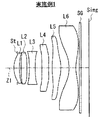
図1は、本開示の一実施の形態に係る撮像レンズの第1の構成例を示している。この第1の構成例は、後述の数値実施例1のレンズ構成に対応している。同様にして、後述の数値実施例2ないし14のレンズ構成に対応する第2ないし第14の構成例の断面構成を、図2〜図14に示す。図1〜図14において、符号Simgは像面、Z1は光軸を示す。
[1. Basic lens configuration]
FIG. 1 illustrates a first configuration example of an imaging lens according to an embodiment of the present disclosure. This first configuration example corresponds to the lens configuration of Numerical Example 1 described later. Similarly, cross-sectional configurations of second to fourteenth configuration examples corresponding to lens configurations of numerical examples 2 to 14 described later are shown in FIGS. 1 to 14, the symbol Simg indicates an image plane, and Z1 indicates an optical axis.
本実施の形態に係る撮像レンズは、光軸Z1に沿って物体側より順に、第1レンズL1と、第2レンズL2と、第3レンズL3と、第4レンズL4と、第5レンズL5と、第6レンズL6とが配置された、実質的に6つのレンズで構成されている。 The imaging lens according to the present embodiment includes, in order from the object side along the optical axis Z1, a first lens L1, a second lens L2, a third lens L3, a fourth lens L4, and a fifth lens L5. The sixth lens L6 is substantially composed of six lenses.
第1レンズL1は、正の屈折力を有している。第2レンズL2は、正または負の屈折力を有している。第3レンズL3は、負の屈折力を有している。第4レンズL4は、負の屈折力を有している。第5レンズL5は、正の屈折力を有している。第6レンズL6は、負の屈折力を有している。第6レンズL6は、像側の面が、中心部から周辺部に行くに従い、凹凸形状が途中で変化するような変曲点を有する非球面形状であり、光軸Z1との交点以外に少なくとも1つの変曲点を有している。 The first lens L1 has a positive refractive power. The second lens L2 has a positive or negative refractive power. The third lens L3 has negative refractive power. The fourth lens L4 has a negative refractive power. The fifth lens L5 has a positive refractive power. The sixth lens L6 has negative refractive power. The sixth lens L6 has an aspherical shape with an inflection point such that the concave-convex shape changes midway as the image side surface moves from the center to the periphery, and at least other than the intersection with the optical axis Z1. It has one inflection point.
その他、本実施の形態に係る撮像レンズは、後述する所定の条件式等を満足することが好ましい。 In addition, it is preferable that the imaging lens according to the present embodiment satisfies a predetermined conditional expression described later.
[2.作用・効果]
次に、本実施の形態に係る撮像レンズの作用および効果を説明する。
[2. Action / Effect]
Next, functions and effects of the imaging lens according to the present embodiment will be described.
この撮像レンズでは、第6レンズL6の像側の面が非球面形状となり、光軸Z1との交点以外に少なくとも1つの変曲点を有している。この非球面形状にすることで、画角が大きくなることに伴う主光線の跳ね上げを抑制することができるので、適正な角度で撮像素子に光線を入射させることができる。物体側から順に、正の屈折力を有する第1レンズL1と、正または負の屈折力を有する第2レンズL2と、負の屈折力を有する第3レンズL3と、負の屈折力を有する第4レンズL4と、正の屈折力を有する第5レンズL5と、負の屈折力を有する第6レンズL6とを配置し、第6レンズL6を上記した非球面形状とすることで、良好な光学性能を持つレンズを提供することができる。 In this imaging lens, the image-side surface of the sixth lens L6 has an aspherical shape, and has at least one inflection point other than the intersection with the optical axis Z1. By using this aspherical shape, it is possible to suppress the principal ray from jumping up as the angle of view increases, so that the light beam can be incident on the image sensor at an appropriate angle. In order from the object side, a first lens L1 having a positive refractive power, a second lens L2 having a positive or negative refractive power, a third lens L3 having a negative refractive power, and a first lens having a negative refractive power. The four lenses L4, the fifth lens L5 having a positive refractive power, and the sixth lens L6 having a negative refractive power are arranged, and the sixth lens L6 has the above-mentioned aspherical shape, so that a good optical performance can be obtained. A lens with performance can be provided.
この撮像レンズでは、6枚のレンズから構成されていることで、軸上光線および軸外光線ともに緩やかに光線を曲げて行くことが可能であり、その結果、光量を調整する開口絞りStの位置は、以下の2パターンでの実施が可能になる。 Since this imaging lens is composed of six lenses, it is possible to gently bend both on-axis rays and off-axis rays, and as a result, the position of the aperture stop St that adjusts the amount of light. Can be implemented in the following two patterns.
1つ目としては、開口絞りStを第1レンズL1の物体側に配置することにより、入射瞳位置を像面から遠い位置にとることができる。これにより、高いテレセントリック性を確保することが可能となり、像面に対する入射角を好適化することができる。2つ目としては、第1レンズL1と第2レンズL2との間に開口絞りStを配置することで、第1レンズL1の像側の面と第2レンズL2の物体側の面とが対称形状に近い形となり、周辺マージナル光線が発生する収差を打ち消すことができる配置にすることが可能となる。具体例としては、図4の第4の構成例では、第1レンズL1と第2レンズL2との間に開口絞りStを配置している。 First, by arranging the aperture stop St on the object side of the first lens L1, the entrance pupil position can be set at a position far from the image plane. As a result, high telecentricity can be ensured, and the incident angle with respect to the image plane can be optimized. Second, by arranging an aperture stop St between the first lens L1 and the second lens L2, the image side surface of the first lens L1 and the object side surface of the second lens L2 are symmetrical. It becomes a shape close to the shape, and it is possible to make an arrangement that can cancel out the aberration generated by the peripheral marginal ray. As a specific example, in the fourth configuration example of FIG. 4, an aperture stop St is arranged between the first lens L1 and the second lens L2.
また、この撮像レンズでは、第1レンズL1ないし第6レンズL6の全てを樹脂材料で構成することで、大量に安価で非球面のレンズを使用することが可能になる。一方で、更に高い光学性能が要求される場合には、第1レンズL1ないし第6レンズL6のうち、第1レンズL1もしくは第2レンズL2のみをガラス材料で構成しても良い。これにより、高画素化に対応することが可能となる。特に、ガラス材料を用いた場合、レンズ系の前にあるレンズの屈折率を上げることができるので、その結果Fnoを決定するためのマージナル光線の最小偏角を小さくすることができるので大口径化することが可能になる。同時に、ガラス材料を用いた場合は、樹脂材料に比べて低分散のアッべ数を選択することもできる。その結果、軸上色収差補正がさらに容易になるので、こちらの場合でも高い収差補正をすることが可能となる。 Further, in this imaging lens, all of the first lens L1 to the sixth lens L6 are made of a resin material, so that it is possible to use a large amount of inexpensive aspherical lenses. On the other hand, when higher optical performance is required, only the first lens L1 or the second lens L2 of the first lens L1 to the sixth lens L6 may be made of a glass material. Thereby, it becomes possible to cope with an increase in the number of pixels. In particular, when a glass material is used, the refractive index of the lens in front of the lens system can be increased. As a result, the minimum deflection angle of the marginal ray for determining Fno can be reduced, so that the aperture is increased. It becomes possible to do. At the same time, when a glass material is used, an Abbe number having a low dispersion can be selected as compared with a resin material. As a result, axial chromatic aberration correction is further facilitated, so that even in this case, high aberration correction can be performed.
また、この撮像レンズでは、第3レンズL3と第4レンズL4とを同じ材料にすることで、製造にかかるコストを低廉なものにできるのと同時に、軸上色収差補正として重要な機能をする第3レンズL3と第4レンズL4との材料のロット差による光学性能の変動を最低限に抑えることが可能となる。 Further, in this imaging lens, the third lens L3 and the fourth lens L4 are made of the same material, so that the manufacturing cost can be reduced, and at the same time, an important function as axial chromatic aberration correction can be achieved. Variations in optical performance due to material lot differences between the third lens L3 and the fourth lens L4 can be minimized.
以上のように本実施の形態によれば、全体として6枚のレンズ構成とし、各レンズの構成の最適化を図るようにしたので、小型で、諸収差が好適に補正された、良好な光学特性を実現できる。特に、負の屈折力を持つレンズを3つ以上配置させると共に、後述するように、第1レンズL1と第2レンズL2とのパワー配分、および第3レンズL3と第4レンズL4とのパワー配分を適切に定めた構成にすることで、5枚以下のレンズ構成では成しえなかった、高解像化に伴った撮像素子の大型化や画素の高細密化にも対応可能となり、諸収差が良好に補正された高性能なレンズをコンパクトな構成で、安価に提供できる。 As described above, according to the present embodiment, the configuration of the six lenses as a whole is made and the configuration of each lens is optimized, so that the optical system is compact and has various aberrations corrected appropriately. The characteristics can be realized. In particular, three or more lenses having negative refractive power are arranged, and power distribution between the first lens L1 and the second lens L2, and power distribution between the third lens L3 and the fourth lens L4, as will be described later. By properly configuring the lens, it becomes possible to cope with the increase in the size of the image sensor and the increase in the pixel density associated with higher resolution, which could not be achieved with a lens configuration of five or less lenses. A high-performance lens with good correction can be provided at a low cost with a compact configuration.
(条件式の説明)
本実施の形態に係る撮像レンズでは、以下の条件式を少なくとも1つ、好ましくは2つ以上の条件式を組み合わせて満足するように各レンズの構成の最適化を図ることで、より良好な性能を得ることができる。
(Explanation of conditional expressions)
In the imaging lens according to the present embodiment, by optimizing the configuration of each lens so as to satisfy at least one of the following conditional expressions, preferably a combination of two or more conditional expressions, better performance is achieved. Can be obtained.
14≦ν3≦35 ……(1)
ただし、
ν3:第3レンズL3のアッべ数
とする。
14 ≦ ν3 ≦ 35 (1)
However,
ν3: The Abbe number of the third lens L3.
条件式(1)は、第3レンズL3のアッベ数を規定するための条件式である。ここで、第3レンズL3のアッべ数は色収差の補正に大きな影響を及ぼす。条件式(1)の値が上限を上回ってしまうと、f線やg線の屈折力が十分に得られないために、軸上色収差を補正することができなくなってしまう。
なお、適度に色収差を抑えて性能改善を図るためには、上記条件式(1)の数値範囲を以下の条件式(1)’の通り、設定することが好ましい。
18<ν3<31 ……(1)’
Conditional expression (1) is a conditional expression for defining the Abbe number of the third lens L3. Here, the Abbe number of the third lens L3 greatly affects the correction of chromatic aberration. If the value of the conditional expression (1) exceeds the upper limit, the refractive power of the f-line and g-line cannot be obtained sufficiently, so that the axial chromatic aberration cannot be corrected.
In order to improve performance by appropriately suppressing chromatic aberration, it is preferable to set the numerical range of the conditional expression (1) as the following conditional expression (1) ′.
18 <ν3 <31 (1) ′
20≦ν5≦60 ……(2)
ただし、
ν5:第5レンズL5のアッべ数
とする。
20 ≦ ν5 ≦ 60 (2)
However,
ν5: The Abbe number of the fifth lens L5.
条件式(2)は、第5レンズL5のアッべ数を規定するための条件式である。ここで、第5レンズL5のアッべ数は第3レンズL3と同様に色収差の補正に大きな影響を及ぼす。条件式(2)の値が上限を上回ってしまうと、像高の高い周辺を通過するf線やg線の屈折力が得られないために倍率色収差が抑えることができなくなってしまう。条件式(2)の値が下限を下回ってしまうと、今度は第5レンズL5の近軸を通過するf線やg線の屈折力が過剰となってしまい、その結果、軸上色収差を抑えることができなくなってしまう。 Conditional expression (2) is a conditional expression for defining the Abbe number of the fifth lens L5. Here, like the third lens L3, the Abbe number of the fifth lens L5 has a great influence on correction of chromatic aberration. If the value of the conditional expression (2) exceeds the upper limit, the chromatic aberration of magnification cannot be suppressed because the refractive power of f-line and g-line passing through the periphery having a high image height cannot be obtained. If the value of conditional expression (2) falls below the lower limit, then the refractive power of the f-line and g-line passing through the paraxial axis of the fifth lens L5 becomes excessive, and as a result, axial chromatic aberration is suppressed. It becomes impossible to do.
0.4≦f1to2/f≦1.0 ……(3)
ただし、
f:全系の焦点距離
f1to2:第1レンズL1と第2レンズL2との合成焦点距離
とする。
0.4 ≦ f1to2 / f ≦ 1.0 (3)
However,
f: Focal length of the entire system f1to2: The combined focal length of the first lens L1 and the second lens L2.
条件式(3)は、第1レンズL1と第2レンズL2との合成の焦点距離に対する、全系の焦点距離の関係を規定する式である。ここで、第1レンズL1と第2レンズL2との合成焦点距離、つまり合成パワーは、撮像レンズ全体の収差補正や全体の大きさに大きな影響を及ぼす。条件式(3)の値が上限を上回ってしまうと、入射してきた光線を屈折する力が弱くなり全系として大きくなってしまうために小型化を達成することができない。また、条件式(3)の値が下限を下回ってしまうと、第1レンズL1と第2レンズL2との合成パワーが強くなりすぎることで高次の球面収差やコマ収差が発生してしまい、光学性能を確保することができなくなってしまう。
なお、より全長を抑えつつ、高次の球面収差を抑えて性能の改善が図るためには、上記条件式(3)の数値範囲を以下の条件式(3)’の通り、設定することが好ましい。
0.45≦f1to2/f≦0.95 ……(3)’
Conditional expression (3) is an expression that defines the relationship of the focal length of the entire system with respect to the combined focal length of the first lens L1 and the second lens L2. Here, the combined focal length of the first lens L1 and the second lens L2, that is, the combined power, greatly affects the aberration correction and the overall size of the entire imaging lens. If the value of the conditional expression (3) exceeds the upper limit, the force for refracting the incident light beam becomes weak and the entire system becomes large, so that downsizing cannot be achieved. If the value of conditional expression (3) falls below the lower limit, the combined power of the first lens L1 and the second lens L2 becomes too strong, resulting in higher-order spherical aberration and coma aberration. Optical performance cannot be ensured.
In order to improve performance by suppressing higher-order spherical aberration while suppressing the overall length, the numerical range of the conditional expression (3) can be set as the following conditional expression (3) ′. preferable.
0.45 ≦ f1to2 / f ≦ 0.95 (3) ′
−1≦f1/f2≦30 ……(4)
ただし、
f1:第1レンズL1の焦点距離
f2:第2レンズL2の焦点距離
とする。
−1 ≦ f1 / f2 ≦ 30 (4)
However,
f1: The focal length of the first lens L1 f2: The focal length of the second lens L2.
条件式(4)は、第1レンズL1の焦点距離に対する第2レンズL2の焦点距離の関係を規定する式である。ここで、第1レンズL1の焦点距離と第2レンズL2の焦点距離の比、つまりパワーの配分は撮像レンズ全体の収差補正に大きな影響を及ぼす。条件式(4)の値が上限を上回ってしまうと、第1レンズL1と第2レンズL2とで構成される正のパワー群の主点位置が像面側に近づく方向になってしまう。その結果として、光学系が低背化できなくなってしまう。また、条件式(4)の値が下限を下回ってしまうと、第1レンズL1の屈折力を必要以上に高めることになり、その結果、第1レンズL1の物体側の面を通過する周辺マージナル光線の屈折角が大きくなりすぎ収差補正が行えなくなってしまう。
なお、より収差補正を良好にして性能を高めた実施形態とするためには、上記条件式(4)の数値範囲を以下の条件式(4)’の通り、設定することが好ましい。
−0.5≦f1/f2≦22 ……(4)’
Conditional expression (4) is an expression that defines the relationship of the focal length of the second lens L2 to the focal length of the first lens L1. Here, the ratio of the focal length of the first lens L1 and the focal length of the second lens L2, that is, the power distribution, has a great influence on the aberration correction of the entire imaging lens. If the value of conditional expression (4) exceeds the upper limit, the principal point position of the positive power group constituted by the first lens L1 and the second lens L2 will be in a direction approaching the image plane side. As a result, the optical system cannot be reduced in height. If the value of conditional expression (4) falls below the lower limit, the refractive power of the first lens L1 is increased more than necessary, and as a result, the peripheral marginal passing through the object side surface of the first lens L1. The refraction angle of the light beam becomes too large and aberration correction cannot be performed.
In order to obtain an embodiment in which the aberration correction is improved and the performance is improved, it is preferable to set the numerical range of the conditional expression (4) as the following conditional expression (4) ′.
−0.5 ≦ f1 / f2 ≦ 22 (4) ′
0≦f3/f4≦1.0 ……(5)
ただし、
f3:第3レンズL3の焦点距離
f4:第4レンズL4の焦点距離
とする。
0 ≦ f3 / f4 ≦ 1.0 (5)
However,
f3: focal length of the third lens L3 f4: focal length of the fourth lens L4.
条件式(5)は、第3レンズL3の焦点距離と第4レンズL4の焦点距離との関係を規定する式である。ここで、第3レンズL3の焦点距離と第4レンズL4の焦点距離の比は、倍率色収差とコマ収差補正に対して大きな影響を及ぼしている。条件式(5)の値が上限を上回ってしまうと、第4レンズL4のパワーが強くなってしまっているので、周辺画角の主光線が通過する際に分散の影響を大きく受け、その結果、倍率色収差が悪化してしまう。また、条件式(5)の値が下限を下回ってしまうと、第3レンズL3の屈折力を必要以上に高めることになり、その結果、上光線の屈折角が大きくなりすぎ、コマ収差補正ができなくなってしまう。
なお、倍率色収差を抑えつつ、コマ収差を押さえて性能の改善が図るためには、上記条件式(5)の数値範囲を以下の条件式(5)’の通り、設定することが好ましい。
0.03≦f3/f4≦0.8 ……(5)’
Conditional expression (5) is an expression that defines the relationship between the focal length of the third lens L3 and the focal length of the fourth lens L4. Here, the ratio of the focal length of the third lens L3 and the focal length of the fourth lens L4 has a great influence on the lateral chromatic aberration and the coma aberration correction. If the value of the conditional expression (5) exceeds the upper limit, the power of the fourth lens L4 becomes strong, so that it is greatly affected by dispersion when the principal ray of the peripheral angle of view passes, and as a result. The chromatic aberration of magnification will be worsened. Further, if the value of conditional expression (5) falls below the lower limit, the refractive power of the third lens L3 is increased more than necessary, and as a result, the refraction angle of the upper ray becomes too large, and coma aberration correction is performed. It becomes impossible.
In order to improve the performance by suppressing the coma aberration while suppressing the lateral chromatic aberration, it is preferable to set the numerical range of the conditional expression (5) as the following conditional expression (5) ′.
0.03 ≦ f3 / f4 ≦ 0.8 (5) ′
−10≦(R9+R10)/(R9−R10)≦1 ……(6)
ただし、
R9:第5レンズL5の物体側の面の曲率半径
R10:第5レンズL5の像側の面の曲率半径
とする。
−10 ≦ (R9 + R10) / (R9−R10) ≦ 1 (6)
However,
R9: radius of curvature of object side surface of fifth lens L5 R10: radius of curvature of image side surface of fifth lens L5.
条件式(6)は、第5レンズL5の形状を規定する式である。ここで、第5レンズL5の近軸付近の形状は球面収差の補正に影響を及ぼしている。第5レンズL5は、特に、両凸形状、もしくは物体側の面を凸形状のメニスカスレンズとすることが望ましい。条件式(6)の値が上限を上回ってしまうと、第5レンズL5の物体側の面においてFnoを決定するための光線を集光するための屈折力が弱くなるために球面収差補正が難しくなり、その結果、大口径化ができなくなってしまう。また、条件式(6)の値が下限を下回ってしまうと、第5レンズL5の像側の面のパワーが必要以上に強くなってしまい、軸外の画角に対して高次収差を発生させてしまうことによって光学性能が劣化してしまう。
なお、より球面収差を抑えつつ高次収差も発生させないためには、上記条件式(6)の数値範囲を以下の条件式(6)’の通り、設定することが好ましい。
−5≦(R9+R10)/(R9−R10)≦0.75 ……(6)’
Conditional expression (6) defines the shape of the fifth lens L5. Here, the shape near the paraxial axis of the fifth lens L5 affects the correction of the spherical aberration. In particular, the fifth lens L5 is desirably a biconvex shape or a meniscus lens having a convex surface on the object side. If the value of the conditional expression (6) exceeds the upper limit, the spherical aberration correction becomes difficult because the refractive power for condensing the light beam for determining Fno is weak on the object side surface of the fifth lens L5. As a result, the diameter cannot be increased. If the value of conditional expression (6) falls below the lower limit, the power of the image side surface of the fifth lens L5 becomes stronger than necessary, and high-order aberrations are generated with respect to the off-axis angle of view. Doing so will degrade the optical performance.
In order to suppress spherical aberration and prevent higher order aberrations, it is preferable to set the numerical range of the conditional expression (6) as the following conditional expression (6) ′.
−5 ≦ (R9 + R10) / (R9−R10) ≦ 0.75 (6) ′
−5≦(R11+R12)/(R11−R12)≦10 ……(7)
ただし、
R11:第6レンズL6の物体側の面の曲率半径
R12:第6レンズL6の像側の面の曲率半径
とする。
−5 ≦ (R11 + R12) / (R11−R12) ≦ 10 (7)
However,
R11: radius of curvature of object side surface of sixth lens L6 R12: radius of curvature of image side surface of sixth lens L6.
条件式(7)は、第6レンズL6の形状を規定する式である。ここで、第6レンズL6についても近軸付近の形状は球面収差の補正に影響を及ぼしている。条件式(7)の値が範囲内に収まっていることで、光学系の明るさを規定する入射瞳上のマージナル光線を最小偏角に近い形で屈折させることが可能となる。特に、軸上光線群は第5レンズL5以降を通過していく際は近軸領域に近いエリアを通過していくので、これらを緩やかに屈折させていく効果でより高い収差補正が可能となる。
なお、より球面収差を抑えるためには、上記条件式(7)の数値範囲を以下の条件式(7)’の通り、設定することが好ましい。
−2.5≦(R11+R12)/(R11−R12)≦5 ……(7)’
Conditional expression (7) defines the shape of the sixth lens L6. Here, the shape near the paraxial axis of the sixth lens L6 also affects the correction of spherical aberration. When the value of conditional expression (7) is within the range, it becomes possible to refract the marginal ray on the entrance pupil that defines the brightness of the optical system in a form close to the minimum deflection angle. In particular, when the axial ray group passes through the fifth lens L5 and thereafter, it passes through an area close to the paraxial region, so that higher aberration correction can be achieved by the effect of gently refracting them. .
In order to further suppress the spherical aberration, it is preferable to set the numerical range of the conditional expression (7) as the following conditional expression (7) ′.
−2.5 ≦ (R11 + R12) / (R11−R12) ≦ 5 (7) ′
[3.撮像装置への適用例]
図29および図30は、本実施の形態に係る撮像レンズを適用した撮像装置の一構成例を示している。この構成例は、撮像装置を備えた携帯端末機器(例えば携帯情報端末や携帯電話端末)の一例である。この携帯端末機器は、略長方形状の筐体201を備えている。筐体201の前面側(図29)には表示部202やフロントカメラ部203が設けられている。筐体201の背面側(図30)には、メインカメラ部204やカメラフラッシュ205が設けられている。
[3. Application example to imaging device]
29 and 30 show a configuration example of an imaging apparatus to which the imaging lens according to the present embodiment is applied. This configuration example is an example of a mobile terminal device (for example, a mobile information terminal or a mobile phone terminal) provided with an imaging device. This portable terminal device includes a substantially
表示部202は、例えば表面への接触状態を検知することによって各種の操作を可能にするタッチパネルとなっている。これにより、表示部202は、各種の情報を表示する機能とユーザによる各種の入力操作を可能にする入力機能とを有している。表示部202は、操作状態や、フロントカメラ部203またはメインカメラ部204で撮影した画像等の各種のデータを表示する。
The
本実施の形態に係る撮像レンズは、例えば図29および図30に示したような携帯端末機器における撮像装置(フロントカメラ部203またはメインカメラ部204)のカメラモジュール用レンズとして適用可能である。このようなカメラモジュール用レンズとして用いる場合、撮像レンズの像面Simg付近に、撮像レンズによって形成された光学像に応じた撮像信号(画像信号)を出力するCCD(Charge Coupled Devices)やCMOS(Complementary Metal Oxide Semiconductor)等の撮像素子が配置される。この場合、図1に示したように、第6レンズL6と像面Simgとの間には、撮像素子保護用のシールガラスSGや各種の光学フィルタ等の光学部材が配置されていても良い。
The imaging lens according to the present embodiment can be applied as a camera module lens of an imaging device (
なお、本実施の形態に係る撮像レンズは、上記した携帯端末機器に限らず、その他の電子機器、例えばデジタルスチルカメラやデジタルビデオカメラ用の撮像レンズとしても適用可能である。その他、CCDやCMOSなどの固体撮像素子を使用した小型の撮像装置全般、例えば光センサー、携帯用モジュールカメラ、およびWEBカメラなどに適用可能である。 Note that the imaging lens according to the present embodiment is not limited to the above-described portable terminal device, but can also be applied as an imaging lens for other electronic devices such as a digital still camera and a digital video camera. In addition, the present invention can be applied to general small-sized imaging devices using a solid-state imaging device such as a CCD or CMOS, for example, an optical sensor, a portable module camera, and a WEB camera.
<4.レンズの数値実施例>
次に、本実施の形態に係る撮像レンズの具体的な数値実施例について説明する。
なお、以下の各表や説明において示した記号の意味等については、下記に示す通りである。「Si」は、最も物体側の構成要素の面を1番目として、像側に向かうに従い順次増加するようにして符号を付したi番目の面の番号を示している。「Ri」は、i番目の面の近軸の曲率半径の値(mm)を示す。「Di」はi番目の面とi+1番目の面との間の光軸上の間隔の値(mm)を示す。「Ni」はi番目の面を有する光学要素の材質のd線(波長587.6nm)における屈折率の値を示す。「νi」はi番目の面を有する光学要素の材質のd線におけるアッベ数の値を示す。面番号に関し「ASP」は当該面が非球面であることを示し、曲率半径に関し「∞」は当該面が平面または絞り面であることを示す。ωは半画角、FnoはFナンバーを示す。
<4. Numerical Examples of Lens>
Next, specific numerical examples of the imaging lens according to the present embodiment will be described.
In addition, the meanings of symbols shown in the following tables and descriptions are as shown below. “Si” indicates the number of the i-th surface that is numbered sequentially so as to increase toward the image side, with the surface of the component closest to the object side being the first. “Ri” indicates the value (mm) of the paraxial radius of curvature of the i-th surface. “Di” indicates the value (mm) of the distance on the optical axis between the i-th surface and the i + 1-th surface. “Ni” indicates the value of the refractive index at the d-line (wavelength 587.6 nm) of the material of the optical element having the i-th surface. “Νi” represents the value of the Abbe number in the d-line of the material of the optical element having the i-th surface. Regarding the surface number, “ASP” indicates that the surface is an aspheric surface, and regarding the radius of curvature, “∞” indicates that the surface is a flat surface or a diaphragm surface. ω represents a half angle of view, and Fno represents an F number.
各実施例において、非球面の形状は次式で表される。非球面係数のデータにおいて、記号“E”は、その次に続く数値が10を底とした“べき指数”であることを示し、その10を底とした指数関数で表される数値が“E”の前の数値に乗算されることを示す。例えば、「1.0E−05」であれば、「1.0×10⁻⁵」であることを示す。
In each embodiment, the shape of the aspheric surface is expressed by the following equation. In the aspheric coefficient data, the symbol “E” indicates that the next numerical value is a “power exponent” with a base of 10, and the numerical value represented by an exponential function with the
(非球面の式)
非球面の形状は、面の頂点を原点とし、光軸方向にX軸を取り、光軸Z1と垂直方向の高さをhとして以下の数式で表す。
X=(h2/R)/[1+{1−(1+K)(h2/R2)}1/2]+ΣAi・hi
ただし、
R:近軸曲率半径
K:円錐定数
Ai:第i次(iは3以上の整数)の非球面係数
とする。
(Aspherical formula)
The aspherical shape is expressed by the following mathematical formula where the vertex of the surface is the origin, the X axis is taken in the optical axis direction, and the height in the direction perpendicular to the optical axis Z1 is h.
X = (h 2 / R) / [1+ {1− (1 + K) (h 2 / R 2 )} 1/2 ] + ΣAi · h i
However,
R: Paraxial radius of curvature K: Conical constant Ai: An aspherical coefficient of i-th order (i is an integer of 3 or more).
(各数値実施例に共通の構成)
以下の各数値実施例に係る撮像レンズはいずれも、上記したレンズの基本構成を満足した構成となっている。また、各数値実施例に係る撮像レンズはいずれも、複数の非球面を有している。第6レンズL6と像面Simgとの間にはシールガラスSGが配置されている。
(Configuration common to each numerical example)
Any of the imaging lenses according to the following numerical examples has a configuration that satisfies the basic configuration of the lens described above. In addition, each imaging lens according to each numerical example has a plurality of aspheric surfaces. A seal glass SG is disposed between the sixth lens L6 and the image plane Simg.
[数値実施例1]
[表1]、[表2]は、図1に示した第1の構成例に係る撮像レンズに対応する具体的なレンズデータを示している。特に[表1]にはその基本的なレンズデータを示し、[表2]には非球面に関するデータを示す。[表1]にはまた、Fno、画角2ω、および全系の焦点距離fの値も示す。
[Numerical Example 1]
[Table 1] and [Table 2] show specific lens data corresponding to the imaging lens according to the first configuration example shown in FIG. In particular, [Table 1] shows the basic lens data, and [Table 2] shows data related to the aspherical surface. [Table 1] also shows values of Fno, angle of view 2ω, and focal length f of the entire system.
この第1の構成例では、第2レンズL2は正の屈折力を有している。開口絞りStは第1レンズL1の物体側に配置されている。また、第1レンズL1ないし第6レンズL6の全てが樹脂材料で構成されている。また、第3レンズL3と第4レンズL4とが同じ材料で構成されている。第1レンズL1ないし第6レンズL6の各面は、第2面、第3面は球面、それ以外の面は非球面となっている。 In the first configuration example, the second lens L2 has a positive refractive power. The aperture stop St is disposed on the object side of the first lens L1. All of the first lens L1 to the sixth lens L6 are made of a resin material. The third lens L3 and the fourth lens L4 are made of the same material. Each surface of the first lens L1 to the sixth lens L6 is a second surface, the third surface is a spherical surface, and the other surfaces are aspherical surfaces.

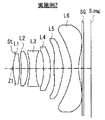
[数値実施例2]
[表3]、[表4]は、図2に示した第2の構成例に係る撮像レンズに対応する具体的なレンズデータを示している。特に[表3]にはその基本的なレンズデータを示し、[表4]には非球面に関するデータを示す。[表3]にはまた、Fno、画角2ω、および全系の焦点距離fの値も示す。
[Numerical Example 2]
[Table 3] and [Table 4] show specific lens data corresponding to the imaging lens according to the second configuration example shown in FIG. In particular, [Table 3] shows the basic lens data, and [Table 4] shows data related to the aspherical surface. [Table 3] also shows values of Fno, angle of view 2ω, and focal length f of the entire system.
この第2の構成例では、第2レンズL2は正の屈折力を有している。開口絞りStは第1レンズL1の物体側に配置されている。また、第1レンズL1ないし第6レンズL6の全てが樹脂材料で構成されている。また、第3レンズL3と第4レンズL4とが同じ材料で構成されている。第1レンズL1ないし第6レンズL6の全ての面が非球面となっている。 In the second configuration example, the second lens L2 has a positive refractive power. The aperture stop St is disposed on the object side of the first lens L1. All of the first lens L1 to the sixth lens L6 are made of a resin material. The third lens L3 and the fourth lens L4 are made of the same material. All surfaces of the first lens L1 to the sixth lens L6 are aspheric.
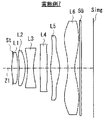
[数値実施例3]
[表5]、[表6]は、図3に示した第3の構成例に係る撮像レンズに対応する具体的なレンズデータを示している。特に[表5]にはその基本的なレンズデータを示し、[表6]には非球面に関するデータを示す。[表5]にはまた、Fno、画角2ω、および全系の焦点距離fの値も示す。
[Numerical Example 3]
[Table 5] and [Table 6] show specific lens data corresponding to the imaging lens according to the third configuration example shown in FIG. In particular, [Table 5] shows the basic lens data, and [Table 6] shows data related to the aspherical surface. [Table 5] also shows values of Fno, angle of view 2ω, and focal length f of the entire system.
この第3の構成例では、第2レンズL2は正の屈折力を有している。開口絞りStは第1レンズL1の物体側に配置されている。また、第1レンズL1ないし第6レンズL6の全てが樹脂材料で構成されている。また、第3レンズL3と第4レンズL4とが同じ材料で構成されている。第1レンズL1ないし第6レンズL6の各面は、第2面、第3面は球面、それ以外の面は非球面となっている。 In the third configuration example, the second lens L2 has a positive refractive power. The aperture stop St is disposed on the object side of the first lens L1. All of the first lens L1 to the sixth lens L6 are made of a resin material. The third lens L3 and the fourth lens L4 are made of the same material. Each surface of the first lens L1 to the sixth lens L6 is a second surface, the third surface is a spherical surface, and the other surfaces are aspherical surfaces.
[数値実施例4]
[表7]、[表8]は、図4に示した第4の構成例に係る撮像レンズに対応する具体的なレンズデータを示している。特に[表7]にはその基本的なレンズデータを示し、[表8]には非球面に関するデータを示す。[表7]にはまた、Fno、画角2ω、および全系の焦点距離fの値も示す。
[Numerical Example 4]
[Table 7] and [Table 8] show specific lens data corresponding to the imaging lens according to the fourth configuration example shown in FIG. In particular, [Table 7] shows the basic lens data, and [Table 8] shows data related to the aspherical surface. [Table 7] also shows values of Fno, angle of view 2ω, and focal length f of the entire system.
この第4の構成例では、第2レンズL2は負の屈折力を有している。開口絞りStは第1レンズL1と第2レンズL2との間に配置されている。また、第1レンズL1ないし第6レンズL6のうち、第1レンズL1のみがガラス材料で構成されている。また、第3レンズL3と第4レンズL4とが同じ材料で構成されている。第1レンズL1ないし第6レンズL6の各面は、第1面、第2面は球面、それ以外の面は非球面となっている。 In the fourth configuration example, the second lens L2 has a negative refractive power. The aperture stop St is disposed between the first lens L1 and the second lens L2. Of the first lens L1 to the sixth lens L6, only the first lens L1 is made of a glass material. The third lens L3 and the fourth lens L4 are made of the same material. The surfaces of the first lens L1 to the sixth lens L6 are a first surface, a second surface is a spherical surface, and the other surfaces are aspherical surfaces.
[数値実施例5]
[表9]、[表10]は、図5に示した第5の構成例に係る撮像レンズに対応する具体的なレンズデータを示している。特に[表9]にはその基本的なレンズデータを示し、[表10]には非球面に関するデータを示す。[表9]にはまた、Fno、画角2ω、および全系の焦点距離fの値も示す。
[Numerical Example 5]
[Table 9] and [Table 10] show specific lens data corresponding to the imaging lens according to the fifth configuration example shown in FIG. In particular, [Table 9] shows the basic lens data, and [Table 10] shows data related to the aspherical surface. [Table 9] also shows values of Fno, angle of view 2ω, and focal length f of the entire system.
この第5の構成例では、第2レンズL2は負の屈折力を有している。開口絞りStは第1レンズL1の物体側に配置されている。また、第1レンズL1ないし第6レンズL6の全てが樹脂材料で構成されている。また、第3レンズL3と第4レンズL4とが同じ材料で構成されている。第1レンズL1ないし第6レンズL6の各面は、第2面、第3面は球面、それ以外の面は非球面となっている。 In the fifth configuration example, the second lens L2 has a negative refractive power. The aperture stop St is disposed on the object side of the first lens L1. All of the first lens L1 to the sixth lens L6 are made of a resin material. The third lens L3 and the fourth lens L4 are made of the same material. Each surface of the first lens L1 to the sixth lens L6 is a second surface, the third surface is a spherical surface, and the other surfaces are aspherical surfaces.
[数値実施例6]
[表11]、[表12]は、図6に示した第6の構成例に係る撮像レンズに対応する具体的なレンズデータを示している。特に[表11]にはその基本的なレンズデータを示し、[表12]には非球面に関するデータを示す。[表11]にはまた、Fno、画角2ω、および全系の焦点距離fの値も示す。
[Numerical Example 6]
[Table 11] and [Table 12] show specific lens data corresponding to the imaging lens according to the sixth configuration example shown in FIG. In particular, [Table 11] shows the basic lens data, and [Table 12] shows data related to the aspherical surface. [Table 11] also shows values of Fno, angle of view 2ω, and focal length f of the entire system.
この第6の構成例では、第2レンズL2は正の屈折力を有している。開口絞りStは第1レンズL1の物体側に配置されている。また、第1レンズL1ないし第6レンズL6の全てが樹脂材料で構成されている。また、第3レンズL3と第4レンズL4とが同じ材料で構成されている。第1レンズL1ないし第6レンズL6の各面は、第2面、第3面は球面、それ以外の面は非球面となっている。 In the sixth configuration example, the second lens L2 has a positive refractive power. The aperture stop St is disposed on the object side of the first lens L1. All of the first lens L1 to the sixth lens L6 are made of a resin material. The third lens L3 and the fourth lens L4 are made of the same material. Each surface of the first lens L1 to the sixth lens L6 is a second surface, the third surface is a spherical surface, and the other surfaces are aspherical surfaces.
[数値実施例7]
[表13]、[表14]は、図7に示した第7の構成例に係る撮像レンズに対応する具体的なレンズデータを示している。特に[表13]にはその基本的なレンズデータを示し、[表14]には非球面に関するデータを示す。[表13]にはまた、Fno、画角2ω、および全系の焦点距離fの値も示す。
[Numerical Example 7]
[Table 13] and [Table 14] show specific lens data corresponding to the imaging lens according to the seventh configuration example shown in FIG. In particular, [Table 13] shows the basic lens data, and [Table 14] shows data related to the aspherical surface. [Table 13] also shows values of Fno, angle of view 2ω, and focal length f of the entire system.
この第7の構成例では、第2レンズL2は正の屈折力を有している。開口絞りStは第1レンズL1の物体側に配置されている。また、第1レンズL1ないし第6レンズL6の全てが樹脂材料で構成されている。また、第3レンズL3と第4レンズL4とが同じ材料で構成されている。第1レンズL1ないし第6レンズL6の全ての面が非球面となっている。 In the seventh configuration example, the second lens L2 has a positive refractive power. The aperture stop St is disposed on the object side of the first lens L1. All of the first lens L1 to the sixth lens L6 are made of a resin material. The third lens L3 and the fourth lens L4 are made of the same material. All surfaces of the first lens L1 to the sixth lens L6 are aspheric.
[数値実施例8]
[表15]、[表16]は、図8に示した第8の構成例に係る撮像レンズに対応する具体的なレンズデータを示している。特に[表15]にはその基本的なレンズデータを示し、[表16]には非球面に関するデータを示す。[表15]にはまた、Fno、画角2ω、および全系の焦点距離fの値も示す。
[Numerical Example 8]
[Table 15] and [Table 16] show specific lens data corresponding to the imaging lens according to the eighth configuration example shown in FIG. In particular, [Table 15] shows basic lens data, and [Table 16] shows data related to aspheric surfaces. [Table 15] also shows values of Fno, angle of view 2ω, and focal length f of the entire system.
この第8の構成例では、第2レンズL2は正の屈折力を有している。開口絞りStは第1レンズL1の物体側に配置されている。また、第1レンズL1ないし第6レンズL6の全てが樹脂材料で構成されている。また、第3レンズL3と第4レンズL4とが同じ材料で構成されている。第1レンズL1ないし第6レンズL6の全ての面が非球面となっている。 In the eighth configuration example, the second lens L2 has a positive refractive power. The aperture stop St is disposed on the object side of the first lens L1. All of the first lens L1 to the sixth lens L6 are made of a resin material. The third lens L3 and the fourth lens L4 are made of the same material. All surfaces of the first lens L1 to the sixth lens L6 are aspheric.
[数値実施例9]
[表17]、[表18]は、図9に示した第9の構成例に係る撮像レンズに対応する具体的なレンズデータを示している。特に[表17]にはその基本的なレンズデータを示し、[表18]には非球面に関するデータを示す。[表17]にはまた、Fno、画角2ω、および全系の焦点距離fの値も示す。
[Numerical Example 9]
[Table 17] and [Table 18] show specific lens data corresponding to the imaging lens according to the ninth configuration example shown in FIG. In particular, [Table 17] shows the basic lens data, and [Table 18] shows data related to the aspherical surface. [Table 17] also shows values of Fno, angle of view 2ω, and focal length f of the entire system.
この第9の構成例では、第2レンズL2は正の屈折力を有している。開口絞りStは第1レンズL1の物体側に配置されている。また、第1レンズL1ないし第6レンズL6の全てが樹脂材料で構成されている。また、第3レンズL3と第4レンズL4とが同じ材料で構成されている。第1レンズL1ないし第6レンズL6の全ての面が非球面となっている。 In the ninth configuration example, the second lens L2 has a positive refractive power. The aperture stop St is disposed on the object side of the first lens L1. All of the first lens L1 to the sixth lens L6 are made of a resin material. The third lens L3 and the fourth lens L4 are made of the same material. All surfaces of the first lens L1 to the sixth lens L6 are aspheric.
[数値実施例10]
[表19]、[表20]は、図10に示した第10の構成例に係る撮像レンズに対応する具体的なレンズデータを示している。特に[表19]にはその基本的なレンズデータを示し、[表20]には非球面に関するデータを示す。[表19]にはまた、Fno、画角2ω、および全系の焦点距離fの値も示す。
[Numerical Example 10]
[Table 19] and [Table 20] show specific lens data corresponding to the imaging lens according to the tenth configuration example shown in FIG. In particular, [Table 19] shows the basic lens data, and [Table 20] shows data related to the aspherical surface. Table 19 also shows the values of Fno, angle of view 2ω, and focal length f of the entire system.
この第10の構成例では、第2レンズL2は正の屈折力を有している。開口絞りStは第1レンズL1の物体側に配置されている。また、第1レンズL1ないし第6レンズL6の全てが樹脂材料で構成されている。また、第3レンズL3と第4レンズL4とが同じ材料で構成されている。第1レンズL1ないし第6レンズL6の全ての面が非球面となっている。 In the tenth configuration example, the second lens L2 has a positive refractive power. The aperture stop St is disposed on the object side of the first lens L1. All of the first lens L1 to the sixth lens L6 are made of a resin material. The third lens L3 and the fourth lens L4 are made of the same material. All surfaces of the first lens L1 to the sixth lens L6 are aspheric.
[数値実施例11]
[表21]、[表22]は、図11に示した第11の構成例に係る撮像レンズに対応する具体的なレンズデータを示している。特に[表21]にはその基本的なレンズデータを示し、[表22]には非球面に関するデータを示す。[表21]にはまた、Fno、画角2ω、および全系の焦点距離fの値も示す。
[Numerical Example 11]
[Table 21] and [Table 22] show specific lens data corresponding to the imaging lens according to the eleventh configuration example shown in FIG. In particular, [Table 21] shows basic lens data, and [Table 22] shows data related to aspheric surfaces. [Table 21] also shows values of Fno, angle of view 2ω, and focal length f of the entire system.
この第11の構成例では、第2レンズL2は正の屈折力を有している。開口絞りStは第1レンズL1の物体側に配置されている。また、第1レンズL1ないし第6レンズL6の全てが樹脂材料で構成されている。また、第3レンズL3と第4レンズL4とが同じ材料で構成されている。第1レンズL1ないし第6レンズL6の全ての面が非球面となっている。 In the eleventh configuration example, the second lens L2 has a positive refractive power. The aperture stop St is disposed on the object side of the first lens L1. All of the first lens L1 to the sixth lens L6 are made of a resin material. The third lens L3 and the fourth lens L4 are made of the same material. All surfaces of the first lens L1 to the sixth lens L6 are aspheric.
[数値実施例12]
[表23]、[表24]は、図12に示した第12の構成例に係る撮像レンズに対応する具体的なレンズデータを示している。特に[表23]にはその基本的なレンズデータを示し、[表24]には非球面に関するデータを示す。[表23]にはまた、Fno、画角2ω、および全系の焦点距離fの値も示す。
[Numerical Example 12]
[Table 23] and [Table 24] show specific lens data corresponding to the imaging lens according to the twelfth configuration example shown in FIG. In particular, [Table 23] shows the basic lens data, and [Table 24] shows data related to the aspherical surface. [Table 23] also shows values of Fno, the angle of view 2ω, and the focal length f of the entire system.
この第12の構成例では、第2レンズL2は正の屈折力を有している。開口絞りStは第1レンズL1の物体側に配置されている。また、第1レンズL1ないし第6レンズL6の全てが樹脂材料で構成されている。また、第3レンズL3と第4レンズL4とが異なる材料で構成されている。第1レンズL1ないし第6レンズL6の全ての面が非球面となっている。 In the twelfth configuration example, the second lens L2 has a positive refractive power. The aperture stop St is disposed on the object side of the first lens L1. All of the first lens L1 to the sixth lens L6 are made of a resin material. Further, the third lens L3 and the fourth lens L4 are made of different materials. All surfaces of the first lens L1 to the sixth lens L6 are aspheric.
[数値実施例13]
[表25]、[表26]は、図13に示した第13の構成例に係る撮像レンズに対応する具体的なレンズデータを示している。特に[表25]にはその基本的なレンズデータを示し、[表26]には非球面に関するデータを示す。[表25]にはまた、Fno、画角2ω、および全系の焦点距離fの値も示す。
[Numerical Example 13]
[Table 25] and [Table 26] show specific lens data corresponding to the imaging lens according to the thirteenth configuration example shown in FIG. In particular, [Table 25] shows the basic lens data, and [Table 26] shows data related to the aspherical surface. [Table 25] also shows values of Fno, angle of view 2ω, and focal length f of the entire system.
この第13の構成例では、第2レンズL2は正の屈折力を有している。開口絞りStは第1レンズL1の物体側に配置されている。また、第1レンズL1ないし第6レンズL6のうち、第2レンズL2のみがガラス材料で構成されている。また、第3レンズL3と第4レンズL4とが異なる材料で構成されている。第1レンズL1ないし第6レンズL6の全ての面が非球面となっている。 In the thirteenth configuration example, the second lens L2 has a positive refractive power. The aperture stop St is disposed on the object side of the first lens L1. Of the first lens L1 to the sixth lens L6, only the second lens L2 is made of a glass material. Further, the third lens L3 and the fourth lens L4 are made of different materials. All surfaces of the first lens L1 to the sixth lens L6 are aspheric.
[数値実施例14]
[表27]、[表28]は、図14に示した第14の構成例に係る撮像レンズに対応する具体的なレンズデータを示している。特に[表27]にはその基本的なレンズデータを示し、[表28]には非球面に関するデータを示す。[表27]にはまた、Fno、画角2ω、および全系の焦点距離fの値も示す。
[Numerical Example 14]
[Table 27] and [Table 28] show specific lens data corresponding to the imaging lens according to the fourteenth configuration example shown in FIG. In particular, [Table 27] shows the basic lens data, and [Table 28] shows data related to the aspherical surface. [Table 27] also shows values of Fno, angle of view 2ω, and focal length f of the entire system.
この第14の構成例では、第2レンズL2は正の屈折力を有している。開口絞りStは第1レンズL1の物体側に配置されている。また、第1レンズL1ないし第6レンズL6のうち、第2レンズL2のみがガラス材料で構成されている。また、第3レンズL3と第4レンズL4とが異なる材料で構成されている。第1レンズL1ないし第6レンズL6の全ての面が非球面となっている。 In the fourteenth configuration example, the second lens L2 has a positive refractive power. The aperture stop St is disposed on the object side of the first lens L1. Of the first lens L1 to the sixth lens L6, only the second lens L2 is made of a glass material. Further, the third lens L3 and the fourth lens L4 are made of different materials. All surfaces of the first lens L1 to the sixth lens L6 are aspheric.
[各実施例のその他の数値データ]
[表29]には、上述の各条件式に関する値を、各数値実施例についてまとめたものを示す。[表29]から分かるように、各条件式について、各数値実施例の値がその数値範囲内となっている。
[Other numerical data of each example]
[Table 29] shows a summary of values relating to the above-described conditional expressions for each numerical example. As can be seen from [Table 29], for each conditional expression, the value of each numerical example falls within the numerical range.
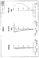
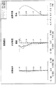
[収差性能]
図15〜図28に、各数値実施例の収差性能を示す。これらの各図には収差図として、球面収差、非点収差、およびディストーション(歪曲収差)を示す。非点収差図において、Sはサジタル方向、Tはメリディオナル(タンジェンシャル)方向の収差を示す。
[Aberration performance]
15 to 28 show the aberration performance of each numerical example. In these drawings, spherical aberration, astigmatism, and distortion (distortion aberration) are shown as aberration diagrams. In the astigmatism diagram, S indicates the sagittal direction, and T indicates the aberration in the meridional (tangential) direction.
以上の各収差図から分かるように、各実施例について、良好に収差補正された撮像レンズを実現できている。 As can be seen from each of the above aberration diagrams, an imaging lens with good aberration correction can be realized for each example.
<5.その他の実施の形態>
本開示による技術は、上記実施の形態および実施例の説明に限定されず種々の変形実施が可能である。
例えば、上記各数値実施例において示した各部の形状および数値は、いずれも本技術を実施するための具体化のほんの一例に過ぎず、これらによって本技術の技術的範囲が限定的に解釈されることがあってはならないものである。
<5. Other Embodiments>
The technology according to the present disclosure is not limited to the description of the above-described embodiments and examples, and various modifications can be made.
For example, the shapes and numerical values of the respective parts shown in the numerical examples are merely examples of embodiments for carrying out the present technology, and the technical scope of the present technology is interpreted in a limited manner by these. There should be no such thing.
また、上記実施の形態および実施例では、実質的に6つのレンズからなる構成について説明したが、実質的に屈折力を有さないレンズをさらに備えた構成であっても良い。 In the above-described embodiments and examples, the configuration including substantially six lenses has been described. However, a configuration further including a lens having substantially no refractive power may be used.
また例えば、本技術は以下のような構成を取ることができる。
[1]
物体側より順に、
正の屈折力を有する第1レンズと、
正または負の屈折力を有する第2レンズと、
負の屈折力を有する第3レンズと、
負の屈折力を有する第4レンズと、
正の屈折力を有する第5レンズと、
負の屈折力を有する第6レンズとからなり、
前記第6レンズの像側の面が、光軸との交点以外に少なくとも1つの変曲点を有する非球面形状である
撮像レンズ。
[2]
以下の条件式を満足する
上記[1]に記載の撮像レンズ。
14≦ν3≦35 ……(1)
ただし、
ν3:前記第3レンズのアッべ数
とする。
[3]
以下の条件式を満足する
上記[1]または[2]に記載の撮像レンズ。
20≦ν5≦60 ……(2)
ただし、
ν5:前記第5レンズのアッべ数
とする。
[4]
以下の条件式を満足する
上記[1]ないし[3]のいずれか1つに記載の撮像レンズ。
0.4≦f1to2/f≦1.0 ……(3)
ただし、
f:全系の焦点距離
f1to2:前記第1レンズと前記第2レンズとの合成焦点距離
とする。
[5]
以下の条件式を満足する
上記[1]ないし[4]のいずれか1つに記載の撮像レンズ。
−1≦f1/f2≦30 ……(4)
ただし、
f1:前記第1レンズの焦点距離
f2:前記第2レンズの焦点距離
とする。
[6]
以下の条件式を満足する
上記[1]ないし[5]のいずれか1つに記載の撮像レンズ。
0≦f3/f4≦1.0 ……(5)
ただし、
f3:前記第3レンズの焦点距離
f4:前記第4レンズの焦点距離
とする。
[7]
以下の条件式を満足する
上記[1]ないし[6]のいずれか1つに記載の撮像レンズ。
−10≦(R9+R10)/(R9−R10)≦1 ……(6)
ただし、
R9:前記第5レンズの物体側の面の曲率半径
R10:前記第5レンズの像側の面の曲率半径
とする。
[8]
以下の条件式を満足する
上記[1]ないし[7]のいずれか1つに記載の撮像レンズ。
−5≦(R11+R12)/(R11−R12)≦10 ……(7)
ただし、
R11:前記第6レンズの物体側の面の曲率半径
R12:前記第6レンズの像側の面の曲率半径
とする。
[9]
前記第1レンズの物体側、または前記第1レンズと前記第2レンズとの間に開口絞りが配置されている
上記[1]ないし[8]のいずれか1つに記載の撮像レンズ。
[10]
前記第1ないし第6レンズの全てが樹脂材料で構成されているか、または前記第1ないし第6レンズのうち、前記第1レンズもしくは前記第2レンズのみがガラス材料で構成されている
上記[1]ないし[9]のいずれか1つに記載の撮像レンズ。
[11]
前記第3レンズと前記第4レンズとが同じ材料である
上記[1]ないし[10]のいずれか1つに記載の撮像レンズ。
[12]
実質的に屈折力を有さないレンズをさらに備えた
上記[1]ないし[11]のいずれか1つに記載の撮像レンズ。
[13]
撮像レンズと、前記撮像レンズによって形成された光学像に応じた撮像信号を出力する撮像素子とを含み、
前記撮像レンズは、
物体側より順に、
正の屈折力を有する第1レンズと、
正または負の屈折力を有する第2レンズと、
負の屈折力を有する第3レンズと、
負の屈折力を有する第4レンズと、
正の屈折力を有する第5レンズと、
負の屈折力を有する第6レンズとからなり、
前記第6レンズの像側の面が、光軸との交点以外に少なくとも1つの変曲点を有する非球面形状である
撮像装置。
[14]
前記撮像レンズは、実質的に屈折力を有さないレンズをさらに備える
上記[13]に記載の撮像装置。
For example, this technique can take the following composition.
[1]
From the object side,
A first lens having a positive refractive power;
A second lens having a positive or negative refractive power;
A third lens having negative refractive power;
A fourth lens having negative refractive power;
A fifth lens having positive refractive power;
A sixth lens having negative refractive power,
The imaging lens, wherein the image side surface of the sixth lens has an aspherical shape having at least one inflection point other than the intersection with the optical axis.
[2]
The imaging lens according to [1], wherein the following conditional expression is satisfied.
14 ≦ ν3 ≦ 35 (1)
However,
ν3: The Abbe number of the third lens.
[3]
The imaging lens according to [1] or [2], wherein the following conditional expression is satisfied.
20 ≦ ν5 ≦ 60 (2)
However,
ν5: The Abbe number of the fifth lens.
[4]
The imaging lens according to any one of [1] to [3], wherein the following conditional expression is satisfied.
0.4 ≦ f1to2 / f ≦ 1.0 (3)
However,
f: Focal length of the entire system f1to2: The combined focal length of the first lens and the second lens.
[5]
The imaging lens according to any one of [1] to [4], wherein the following conditional expression is satisfied.
−1 ≦ f1 / f2 ≦ 30 (4)
However,
f1: The focal length of the first lens f2: The focal length of the second lens.
[6]
The imaging lens according to any one of [1] to [5], wherein the following conditional expression is satisfied.
0 ≦ f3 / f4 ≦ 1.0 (5)
However,
f3: focal length of the third lens f4: focal length of the fourth lens.
[7]
The imaging lens according to any one of [1] to [6], wherein the following conditional expression is satisfied.
−10 ≦ (R9 + R10) / (R9−R10) ≦ 1 (6)
However,
R9: radius of curvature of the object side surface of the fifth lens R10: radius of curvature of the image side surface of the fifth lens.
[8]
The imaging lens according to any one of [1] to [7], wherein the following conditional expression is satisfied.
−5 ≦ (R11 + R12) / (R11−R12) ≦ 10 (7)
However,
R11: radius of curvature of the object side surface of the sixth lens R12: radius of curvature of the image side surface of the sixth lens.
[9]
The imaging lens according to any one of [1] to [8], wherein an aperture stop is disposed on the object side of the first lens or between the first lens and the second lens.
[10]
All of the first to sixth lenses are made of a resin material, or, of the first to sixth lenses, only the first lens or the second lens is made of a glass material. ] The imaging lens according to any one of [9].
[11]
The imaging lens according to any one of [1] to [10], wherein the third lens and the fourth lens are made of the same material.
[12]
The imaging lens according to any one of [1] to [11], further including a lens that has substantially no refractive power.
[13]
An imaging lens, and an imaging element that outputs an imaging signal corresponding to an optical image formed by the imaging lens;
The imaging lens is
From the object side,
A first lens having a positive refractive power;
A second lens having a positive or negative refractive power;
A third lens having negative refractive power;
A fourth lens having negative refractive power;
A fifth lens having positive refractive power;
A sixth lens having negative refractive power,
The imaging device wherein the image side surface of the sixth lens has an aspherical shape having at least one inflection point other than the intersection with the optical axis.
[14]
The imaging device according to [13], wherein the imaging lens further includes a lens having substantially no refractive power.
L1…第1レンズ、L2…第2レンズ、L3…第3レンズ、L4…第4レンズ、L5…第5レンズ、L6…第6レンズ、SG…シールガラス、St…開口絞り、Simg…像面(撮像素子)、Z1…光軸、201…筐体、202…表示部、203…フロントカメラ部、204…メインカメラ部、205…カメラフラッシュ。 L1 ... 1st lens, L2 ... 2nd lens, L3 ... 3rd lens, L4 ... 4th lens, L5 ... 5th lens, L6 ... 6th lens, SG ... Seal glass, St ... Aperture stop, Simg ... Image plane (Imaging element), Z1... Optical axis, 201... Casing, 202... Display unit, 203 .. front camera unit, 204.
Claims (12)
正の屈折力を有する第1レンズと、
正または負の屈折力を有する第2レンズと、
負の屈折力を有する第3レンズと、
負の屈折力を有する第4レンズと、
正の屈折力を有する第5レンズと、
負の屈折力を有する第6レンズとからなり、
前記第6レンズの像側の面が、中心部から周辺部に行くに従い、凹凸形状が途中で変化するような変曲点を有する非球面形状であり、
以下の条件式を満足する
撮像レンズ。
0.4≦f1to2/f≦1.0 ……(3)
−10≦(R9+R10)/(R9−R10)≦1 ……(6)
ただし、
f:全系の焦点距離
f1to2:前記第1レンズと前記第2レンズとの合成焦点距離
R9:前記第5レンズの物体側の面の曲率半径
R10:前記第5レンズの像側の面の曲率半径
とする。 From the object side,
A first lens having a positive refractive power;
A second lens having a positive or negative refractive power;
A third lens having negative refractive power;
A fourth lens having negative refractive power;
A fifth lens having positive refractive power;
A sixth lens having negative refractive power,
Surface on the image side of the sixth lens, as it goes from the center to the periphery, Ri aspherical der having an inflection point such that the uneven shape changes on the way,
An imaging lens that satisfies the following conditional expression .
0.4 ≦ f1to2 / f ≦ 1.0 (3)
−10 ≦ (R9 + R10) / (R9−R10) ≦ 1 (6)
However,
f: Focal length of the entire system
f1to2: Composite focal length of the first lens and the second lens
R9: radius of curvature of the object side surface of the fifth lens
R10: radius of curvature of the image side surface of the fifth lens
And
請求項1に記載の撮像レンズ。
14≦ν3≦35 ……(1)
ただし、
ν3:前記第3レンズのアッべ数
とする。 The imaging lens according to claim 1, wherein the following conditional expression is satisfied.
14 ≦ ν3 ≦ 35 (1)
However,
ν3: The Abbe number of the third lens.
請求項1または2に記載の撮像レンズ。
20≦ν5≦60 ……(2)
ただし、
ν5:前記第5レンズのアッべ数
とする。 The imaging lens according to claim 1, wherein the following conditional expression is satisfied.
20 ≦ ν5 ≦ 60 (2)
However,
ν5: The Abbe number of the fifth lens.
請求項1ないし3のいずれか1つに記載の撮像レンズ。
−1≦f1/f2≦30 ……(4)
ただし、
f1:前記第1レンズの焦点距離
f2:前記第2レンズの焦点距離
とする。 The imaging lens according to any one of claims 1 to 3 , wherein the following conditional expression is satisfied.
−1 ≦ f1 / f2 ≦ 30 (4)
However,
f1: The focal length of the first lens f2: The focal length of the second lens.
請求項1ないし4のいずれか1つに記載の撮像レンズ。
0≦f3/f4≦1.0 ……(5)
ただし、
f3:前記第3レンズの焦点距離
f4:前記第4レンズの焦点距離
とする。 The imaging lens according to any one of claims 1 to 4 , wherein the following conditional expression is satisfied.
0 ≦ f3 / f4 ≦ 1.0 (5)
However,
f3: focal length of the third lens f4: focal length of the fourth lens.
請求項1ないし5のいずれか1つに記載の撮像レンズ。
−5≦(R11+R12)/(R11−R12)≦10 ……(7)
ただし、
R11:前記第6レンズの物体側の面の曲率半径
R12:前記第6レンズの像側の面の曲率半径
とする。 The following claims 1, thereby satisfying the expression to the imaging lens according to any one of the 5.
−5 ≦ (R11 + R12) / (R11−R12) ≦ 10 (7)
However,
R11: radius of curvature of the object side surface of the sixth lens R12: radius of curvature of the image side surface of the sixth lens.
請求項1ないし6のいずれか1つに記載の撮像レンズ。 The imaging lens according to any one of claims 1 to 6 , wherein an aperture stop is disposed on the object side of the first lens or between the first lens and the second lens.
請求項1ないし7のいずれか1つに記載の撮像レンズ。 2. All of the first to sixth lenses are made of a resin material, or, of the first to sixth lenses, only the first lens or the second lens is made of a glass material. The imaging lens according to any one of Items 7 to 7 .
請求項1ないし8のいずれか1つに記載の撮像レンズ。 The imaging lens according to any one of claims 1 to 8 , wherein the third lens and the fourth lens are made of the same material.
請求項1ないし9のいずれか1つに記載の撮像レンズ。 The imaging lens according to to more claims 1 comprises a lens having substantially no refractive power one of 9.
前記撮像レンズは、
物体側より順に、
正の屈折力を有する第1レンズと、
正または負の屈折力を有する第2レンズと、
負の屈折力を有する第3レンズと、
負の屈折力を有する第4レンズと、
正の屈折力を有する第5レンズと、
負の屈折力を有する第6レンズとからなり、
前記第6レンズの像側の面が、中心部から周辺部に行くに従い、凹凸形状が途中で変化するような変曲点を有する非球面形状であり、
以下の条件式を満足する
撮像装置。
0.4≦f1to2/f≦1.0 ……(3)
−10≦(R9+R10)/(R9−R10)≦1 ……(6)
ただし、
f:全系の焦点距離
f1to2:前記第1レンズと前記第2レンズとの合成焦点距離
R9:前記第5レンズの物体側の面の曲率半径
R10:前記第5レンズの像側の面の曲率半径
とする。 An imaging lens, and an imaging element that outputs an imaging signal corresponding to an optical image formed by the imaging lens;
The imaging lens is
From the object side,
A first lens having a positive refractive power;
A second lens having a positive or negative refractive power;
A third lens having negative refractive power;
A fourth lens having negative refractive power;
A fifth lens having positive refractive power;
A sixth lens having negative refractive power,
Surface on the image side of the sixth lens, as it goes from the center to the periphery, Ri aspherical der having an inflection point such that the uneven shape changes on the way,
An imaging apparatus that satisfies the following conditional expression .
0.4 ≦ f1to2 / f ≦ 1.0 (3)
−10 ≦ (R9 + R10) / (R9−R10) ≦ 1 (6)
However,
f: Focal length of the entire system
f1to2: Composite focal length of the first lens and the second lens
R9: radius of curvature of the object side surface of the fifth lens
R10: radius of curvature of the image side surface of the fifth lens
And
請求項11に記載の撮像装置。 The imaging device according to claim 11 , wherein the imaging lens further includes a lens having substantially no refractive power.
Priority Applications (4)
| Application Number | Priority Date | Filing Date | Title |
|---|---|---|---|
| JP2012187995A JP5915462B2 (en) | 2012-08-28 | 2012-08-28 | Imaging lens and imaging apparatus |
| US13/945,145 US9285568B2 (en) | 2012-08-28 | 2013-07-18 | Image pickup lens and image pickup unit |
| TW102129477A TW201421066A (en) | 2012-08-28 | 2013-08-16 | Image pickup lens and image pickup unit |
| CN201310360753.9A CN103676088A (en) | 2012-08-28 | 2013-08-19 | Image pickup lens and image pickup unit |
Applications Claiming Priority (1)
| Application Number | Priority Date | Filing Date | Title |
|---|---|---|---|
| JP2012187995A JP5915462B2 (en) | 2012-08-28 | 2012-08-28 | Imaging lens and imaging apparatus |
Publications (3)
| Publication Number | Publication Date |
|---|---|
| JP2014044372A JP2014044372A (en) | 2014-03-13 |
| JP2014044372A5 JP2014044372A5 (en) | 2015-02-26 |
| JP5915462B2 true JP5915462B2 (en) | 2016-05-11 |
Family
ID=50187080
Family Applications (1)
| Application Number | Title | Priority Date | Filing Date |
|---|---|---|---|
| JP2012187995A Active JP5915462B2 (en) | 2012-08-28 | 2012-08-28 | Imaging lens and imaging apparatus |
Country Status (4)
| Country | Link |
|---|---|
| US (1) | US9285568B2 (en) |
| JP (1) | JP5915462B2 (en) |
| CN (1) | CN103676088A (en) |
| TW (1) | TW201421066A (en) |
Families Citing this family (81)
| Publication number | Priority date | Publication date | Assignee | Title |
|---|---|---|---|---|
| JP5877183B2 (en) * | 2012-09-14 | 2016-03-02 | サムソン エレクトロ−メカニックス カンパニーリミテッド. | Imaging lens |
| JP6033658B2 (en) * | 2012-12-04 | 2016-11-30 | 三星電子株式会社Samsung Electronics Co.,Ltd. | Imaging lens |
| JP2014115431A (en) * | 2012-12-07 | 2014-06-26 | Konica Minolta Inc | Imaging lens, imaging apparatus, and portable terminal |
| TWI510806B (en) | 2013-02-04 | 2015-12-01 | Largan Precision Co Ltd | Optical image capturing system |
| US9804358B2 (en) * | 2013-04-01 | 2017-10-31 | Sony Corporation | Bright large aperture imaging lens and imaging unit |
| TWI470266B (en) | 2013-08-23 | 2015-01-21 | Largan Precision Co Ltd | Optical imaging lens assembly and optical imaging device |
| CN103676089B (en) * | 2013-08-29 | 2016-01-20 | 玉晶光电(厦门)有限公司 | Optical imaging lens and apply the electronic installation of this optical imaging lens |
| CN103777319B (en) * | 2013-09-06 | 2016-09-28 | 玉晶光电(厦门)有限公司 | Portable electronic devices and its optical imaging lens |
| CN103777320B (en) * | 2013-09-06 | 2016-08-10 | 玉晶光电(厦门)有限公司 | Portable electronic devices and its optical imaging lens |
| TWI504924B (en) * | 2013-09-25 | 2015-10-21 | Largan Precision Co Ltd | Photographing lens assembly and image capturing device |
| TWI506297B (en) | 2013-09-25 | 2015-11-01 | Largan Precision Co Ltd | Optical imaging lens assembly and image capturing device |
| TWI467219B (en) | 2013-11-29 | 2015-01-01 | Largan Precision Co Ltd | Image capturing lens assembly, image capturing device and mobile terminal |
| CN103969790B (en) | 2013-12-09 | 2016-05-11 | 玉晶光电(厦门)有限公司 | Optical imaging lens and apply the electronic installation of this optical imaging lens |
| US9104009B2 (en) * | 2013-12-20 | 2015-08-11 | Genius Electronic Optical Co., Ltd. | Optical imaging system and electronic apparatus including the same |
| TWI493218B (en) * | 2014-05-02 | 2015-07-21 | Largan Precision Co Ltd | Photographing optical lens assembly, image capturing unit and mobile device |
| TWI493217B (en) | 2014-05-02 | 2015-07-21 | Largan Precision Co Ltd | Photographic optical lens assembly, image capturing unit and mobile device |
| CN103984084A (en) * | 2014-05-22 | 2014-08-13 | 中山联合光电科技有限公司 | High pixel optical system with small size and distortion |
| TWI489133B (en) | 2014-06-20 | 2015-06-21 | Largan Precision Co Ltd | Image capturing optical system, image capturing device, and portable device |
| JP6319765B2 (en) * | 2014-07-02 | 2018-05-09 | 株式会社オプトロジック | Imaging lens |
| JP6425238B2 (en) | 2014-07-02 | 2018-11-21 | カンタツ株式会社 | Imaging lens |
| TWI533019B (en) | 2014-08-29 | 2016-05-11 | 大立光電股份有限公司 | Imaging lens system, image capturing unit and electronic device |
| TWI540337B (en) * | 2014-10-08 | 2016-07-01 | 先進光電科技股份有限公司 | Optical image capturing system |
| TWI557427B (en) * | 2014-10-09 | 2016-11-11 | 先進光電科技股份有限公司 | Optical image capturing system |
| KR101709836B1 (en) * | 2014-11-17 | 2017-02-23 | 삼성전기주식회사 | Optical system |
| KR101681384B1 (en) * | 2014-11-18 | 2016-11-30 | 삼성전기주식회사 | Lens module |
| TWI553371B (en) * | 2014-11-19 | 2016-10-11 | 先進光電科技股份有限公司 | Optical image capturing system |
| TWI553370B (en) * | 2014-11-19 | 2016-10-11 | 先進光電科技股份有限公司 | Optical image capturing system |
| TWI519808B (en) | 2014-12-05 | 2016-02-01 | 大立光電股份有限公司 | Image capturing optical lens assembly, image capturing device and electronic device |
| TWI541539B (en) | 2014-12-30 | 2016-07-11 | 大立光電股份有限公司 | Imaging optical lens assembly, imaging apparatus and electronic device |
| CN105807409B (en) * | 2014-12-30 | 2018-09-14 | 大立光电股份有限公司 | Camera optical eyeglass group, image-taking device and electronic device |
| TWI534497B (en) | 2014-12-30 | 2016-05-21 | 大立光電股份有限公司 | Optical photographing lens assembly, image capturing device and electronic device |
| TWI531815B (en) | 2014-12-30 | 2016-05-01 | 大立光電股份有限公司 | Photographing optical lens assembly, image capturing device and electronic device |
| US10254510B2 (en) | 2015-01-07 | 2019-04-09 | Zhejiang Sunny Optics Co., Ltd. | Camera lens |
| TWI592686B (en) * | 2015-08-18 | 2017-07-21 | 先進光電科技股份有限公司 | Optical image capturing system |
| TWI585455B (en) * | 2015-10-20 | 2017-06-01 | 大立光電股份有限公司 | Image capturing lens system, image capturing apparatus and electronic device |
| KR102564885B1 (en) * | 2015-11-02 | 2023-08-08 | 삼성전자주식회사 | Short focus lens and optical device with the same |
| CN105445915B (en) * | 2015-12-31 | 2017-08-11 | 浙江舜宇光学有限公司 | Pick-up lens |
| WO2017113557A1 (en) | 2015-12-31 | 2017-07-06 | 浙江舜宇光学有限公司 | Camera lens |
| KR101690479B1 (en) * | 2016-03-07 | 2016-12-28 | 주식회사 세코닉스 | High-resolution photographing lens system |
| US10466501B2 (en) * | 2016-05-26 | 2019-11-05 | Ams Sensors Singapore Pte. Ltd. | Optoelectronic modules including an optical system tilted with respect to a focal plane |
| CN106526796B (en) * | 2016-08-05 | 2019-09-24 | 玉晶光电(厦门)有限公司 | Optical mirror slip group |
| JP6570076B2 (en) | 2016-08-29 | 2019-09-04 | カンタツ株式会社 | Imaging lens |
| TWI594011B (en) | 2016-11-22 | 2017-08-01 | 大立光電股份有限公司 | Photographing optical lens system, image capturing apparatus and electronic device |
| KR101832627B1 (en) | 2016-11-25 | 2018-02-26 | 삼성전기주식회사 | Optical system |
| US11262537B2 (en) | 2017-02-17 | 2022-03-01 | Zhejiang Sunny Optical Co., Ltd | Camera lens assembly including six lenses each having refractive power |
| CN106646832B (en) * | 2017-02-17 | 2022-11-22 | 浙江舜宇光学有限公司 | Camera lens |
| TWI626488B (en) | 2017-03-28 | 2018-06-11 | 大立光電股份有限公司 | Photographing optical lens assembly, image capturing unit and electronic device |
| TWI640811B (en) * | 2017-06-16 | 2018-11-11 | 大立光電股份有限公司 | Photographing lens assembly, image capturing unit and electronic device |
| TWI629531B (en) | 2017-10-25 | 2018-07-11 | 大立光電股份有限公司 | Imaging lens assembly, imaging apparatus and electronic device |
| US20200319430A1 (en) * | 2017-12-28 | 2020-10-08 | Sony Corporation | Imaging lens and imaging apparatus |
| KR102642915B1 (en) * | 2018-03-29 | 2024-03-04 | 삼성전기주식회사 | Optical Imaging System |
| CN108646392B (en) * | 2018-04-26 | 2020-09-18 | 瑞声光学解决方案私人有限公司 | Image pickup optical lens |
| CN108681047B (en) * | 2018-04-26 | 2020-09-18 | 瑞声光学解决方案私人有限公司 | Image pickup optical lens |
| TWI676046B (en) * | 2018-06-20 | 2019-11-01 | 大立光電股份有限公司 | Photographing optical lens assembly, imaging apparatus and electronic device |
| CN108957711B (en) * | 2018-08-02 | 2021-02-26 | 诚瑞光学(苏州)有限公司 | Image pickup optical lens |
| CN108873262B (en) * | 2018-08-03 | 2021-02-26 | 诚瑞光学(苏州)有限公司 | Image pickup optical lens |
| CN111045188B (en) * | 2018-10-11 | 2022-02-11 | 江西晶超光学有限公司 | Optical lens assembly, image capturing module and electronic device |
| TWI674451B (en) | 2018-11-09 | 2019-10-11 | 大立光電股份有限公司 | Imaging optical system, image capturing unit and electronic device |
| CN110007431B (en) * | 2018-12-31 | 2021-07-30 | 瑞声光学解决方案私人有限公司 | Image pickup optical lens |
| CN109613680B (en) * | 2018-12-31 | 2020-11-27 | 诚瑞光学(常州)股份有限公司 | Image pickup optical lens |
| CN109581627B (en) * | 2018-12-31 | 2021-07-09 | 常州市瑞泰光电有限公司 | Image pickup optical lens |
| CN109870786B (en) * | 2018-12-31 | 2021-03-02 | 瑞声光学解决方案私人有限公司 | Image pickup optical lens |
| CN109656000A (en) * | 2019-02-02 | 2019-04-19 | 浙江舜宇光学有限公司 | Pick-up lens group |
| JPWO2020202965A1 (en) * | 2019-03-29 | 2020-10-08 | ||
| CN110187471B (en) * | 2019-05-10 | 2021-08-20 | 诚瑞光学(常州)股份有限公司 | Image pickup optical lens |
| CN110018557B (en) * | 2019-05-24 | 2024-04-02 | 浙江舜宇光学有限公司 | Image pickup lens |
| CN110346905B (en) * | 2019-06-30 | 2021-08-17 | 瑞声光学解决方案私人有限公司 | Image pickup optical lens |
| CN110244437B (en) * | 2019-06-30 | 2021-08-17 | 瑞声光学解决方案私人有限公司 | Image pickup optical lens |
| CN110346906B (en) * | 2019-06-30 | 2021-08-17 | 瑞声光学解决方案私人有限公司 | Image pickup optical lens |
| CN110389424B (en) * | 2019-06-30 | 2021-09-17 | 瑞声光学解决方案私人有限公司 | Image pickup optical lens |
| CN110286471B (en) * | 2019-06-30 | 2021-08-17 | 瑞声光学解决方案私人有限公司 | Image pickup optical lens |
| CN110346909B (en) * | 2019-06-30 | 2021-10-01 | 瑞声光学解决方案私人有限公司 | Image pickup optical lens |
| WO2021026869A1 (en) | 2019-08-15 | 2021-02-18 | 南昌欧菲精密光学制品有限公司 | Optical system, image capturing module and electronic device |
| CN111025543B (en) * | 2019-12-23 | 2021-11-16 | 诚瑞光学(常州)股份有限公司 | Image pickup optical lens |
| WO2021128306A1 (en) * | 2019-12-27 | 2021-07-01 | 南昌欧菲精密光学制品有限公司 | Optical imaging system, image capturing device, and optical device |
| CN111123475B (en) * | 2019-12-30 | 2022-03-15 | 诚瑞光学(常州)股份有限公司 | Image pickup optical lens |
| CN111308651B (en) * | 2020-02-24 | 2022-03-01 | 诚瑞光学(常州)股份有限公司 | Image pickup optical lens |
| CN111158114B (en) * | 2020-02-24 | 2022-01-07 | 诚瑞光学(常州)股份有限公司 | Image pickup optical lens |
| JP6905650B1 (en) * | 2021-03-24 | 2021-07-21 | ジョウシュウシ レイテック オプトロニクス カンパニーリミテッド | Imaging lens |
| CN114578514B (en) * | 2022-03-08 | 2023-07-14 | 浙江舜宇光学有限公司 | Optical imaging system |
| CN116990936A (en) | 2023-06-26 | 2023-11-03 | 辰瑞光学(苏州)有限公司 | Image pickup optical lens |
Family Cites Families (9)
| Publication number | Priority date | Publication date | Assignee | Title |
|---|---|---|---|---|
| CN101819315B (en) | 2009-02-27 | 2014-05-07 | 柯尼卡美能达精密光学株式会社 | Image pickup lens, image pickup apparatus, and mobile terminal |
| JP5095662B2 (en) | 2009-03-31 | 2012-12-12 | カンタツ株式会社 | Imaging lens for solid-state imaging device |
| JP5673680B2 (en) * | 2010-07-16 | 2015-02-18 | コニカミノルタ株式会社 | Imaging lens |
| CN102621664B (en) * | 2011-01-27 | 2014-05-21 | 大立光电股份有限公司 | Image capturing lens assembly |
| TWI432823B (en) * | 2011-06-10 | 2014-04-01 | Largan Precision Co Ltd | Image capturnig lens assembly |
| TWI437258B (en) * | 2011-08-05 | 2014-05-11 | Largan Precision Co Ltd | Optical lens assembly for image taking |
| TWI438475B (en) * | 2011-09-15 | 2014-05-21 | Largan Precision Co Ltd | Optical image capturing lens assembly |
| JP5924121B2 (en) * | 2012-05-22 | 2016-05-25 | 株式会社オプトロジック | Imaging lens |
| TWI474072B (en) * | 2012-06-14 | 2015-02-21 | Largan Precision Co Ltd | Optical image lens system |
-
2012
- 2012-08-28 JP JP2012187995A patent/JP5915462B2/en active Active
-
2013
- 2013-07-18 US US13/945,145 patent/US9285568B2/en active Active
- 2013-08-16 TW TW102129477A patent/TW201421066A/en unknown
- 2013-08-19 CN CN201310360753.9A patent/CN103676088A/en active Pending
Also Published As
| Publication number | Publication date |
|---|---|
| US20140063323A1 (en) | 2014-03-06 |
| US9285568B2 (en) | 2016-03-15 |
| TW201421066A (en) | 2014-06-01 |
| JP2014044372A (en) | 2014-03-13 |
| CN103676088A (en) | 2014-03-26 |
Similar Documents
| Publication | Publication Date | Title |
|---|---|---|
| JP5915462B2 (en) | Imaging lens and imaging apparatus | |
| JP6233408B2 (en) | Imaging lens and imaging apparatus | |
| JP5854227B2 (en) | Imaging lens and imaging apparatus | |
| JP6403711B2 (en) | Imaging lens | |
| JP6021617B2 (en) | Imaging lens | |
| WO2016092944A1 (en) | Imaging lens and imaging device | |
| JP5654384B2 (en) | Imaging lens | |
| JP5992868B2 (en) | Imaging device | |
| WO2017199633A1 (en) | Imaging lens and imaging device | |
| JP2014044250A (en) | Image pickup lens and image pickup device | |
| JP6226369B2 (en) | Wide-angle imaging lens | |
| JP5985904B2 (en) | Imaging lens | |
| JP2014202766A (en) | Imaging lens and imaging apparatus | |
| JP6332851B2 (en) | Imaging lens | |
| TWM484709U (en) | Imaging lens and imaging apparatus including the imaging lens | |
| JP6135674B2 (en) | Imaging lens and imaging apparatus | |
| JP5513648B1 (en) | Imaging lens | |
| JP2015125212A (en) | Imaging lens and imaging unit | |
| JP6001430B2 (en) | Imaging lens | |
| JP2015102850A (en) | Image capturing lens | |
| JP5877523B2 (en) | Imaging lens | |
| JP6474434B2 (en) | Imaging lens | |
| TWM486065U (en) | Imaging lens and imaging apparatus including the imaging lens | |
| JP2006098429A (en) | Imaging lens | |
| JP2015161760A (en) | imaging lens |
Legal Events
| Date | Code | Title | Description |
|---|---|---|---|
| A521 | Written amendment |
Free format text: JAPANESE INTERMEDIATE CODE: A523 Effective date: 20150113 |
|
| A621 | Written request for application examination |
Free format text: JAPANESE INTERMEDIATE CODE: A621 Effective date: 20150113 |
|
| A977 | Report on retrieval |
Free format text: JAPANESE INTERMEDIATE CODE: A971007 Effective date: 20150916 |
|
| A131 | Notification of reasons for refusal |
Free format text: JAPANESE INTERMEDIATE CODE: A131 Effective date: 20150929 |
|
| A521 | Written amendment |
Free format text: JAPANESE INTERMEDIATE CODE: A523 Effective date: 20151119 |
|
| TRDD | Decision of grant or rejection written | ||
| A01 | Written decision to grant a patent or to grant a registration (utility model) |
Free format text: JAPANESE INTERMEDIATE CODE: A01 Effective date: 20160308 |
|
| A61 | First payment of annual fees (during grant procedure) |
Free format text: JAPANESE INTERMEDIATE CODE: A61 Effective date: 20160321 |
|
| R151 | Written notification of patent or utility model registration |
Ref document number: 5915462 Country of ref document: JP Free format text: JAPANESE INTERMEDIATE CODE: R151 |
|
| R250 | Receipt of annual fees |
Free format text: JAPANESE INTERMEDIATE CODE: R250 |
|
| R250 | Receipt of annual fees |
Free format text: JAPANESE INTERMEDIATE CODE: R250 |