WO2017199532A1 - シミュレーション装置、方法、及びコンピュータプログラム - Google Patents
シミュレーション装置、方法、及びコンピュータプログラム Download PDFInfo
- Publication number
- WO2017199532A1 WO2017199532A1 PCT/JP2017/007887 JP2017007887W WO2017199532A1 WO 2017199532 A1 WO2017199532 A1 WO 2017199532A1 JP 2017007887 W JP2017007887 W JP 2017007887W WO 2017199532 A1 WO2017199532 A1 WO 2017199532A1
- Authority
- WO
- WIPO (PCT)
- Prior art keywords
- passenger
- entrance
- area
- alignment
- boarding
- Prior art date
Links
Images


Classifications
-
- B—PERFORMING OPERATIONS; TRANSPORTING
- B66—HOISTING; LIFTING; HAULING
- B66B—ELEVATORS; ESCALATORS OR MOVING WALKWAYS
- B66B3/00—Applications of devices for indicating or signalling operating conditions of elevators
-
- G—PHYSICS
- G06—COMPUTING; CALCULATING OR COUNTING
- G06Q—INFORMATION AND COMMUNICATION TECHNOLOGY [ICT] SPECIALLY ADAPTED FOR ADMINISTRATIVE, COMMERCIAL, FINANCIAL, MANAGERIAL OR SUPERVISORY PURPOSES; SYSTEMS OR METHODS SPECIALLY ADAPTED FOR ADMINISTRATIVE, COMMERCIAL, FINANCIAL, MANAGERIAL OR SUPERVISORY PURPOSES, NOT OTHERWISE PROVIDED FOR
- G06Q10/00—Administration; Management
- G06Q10/04—Forecasting or optimisation specially adapted for administrative or management purposes, e.g. linear programming or "cutting stock problem"
Definitions
- the present invention relates to a simulation of alignment behavior.
- the waiting behavior of passengers at the place of getting on and off of the transportation system has a great influence on waiting time and congestion. For example, if the vicinity of the stairs of a station platform is congested, movement of passengers trying to flow in from the stairs and movement of passengers flowing out of the stairs are hindered, so it is important to grasp standby behavior. In particular, passengers often wait in line when crowded. In this case, depending on the length of the alignment and / or the shape of the alignment, the boarding / alighting time may be shortened or increased even for the same waiting number.
- Patent Document 1 discloses a human flow calculation device that evaluates the mutual influence between the operation of an elevator and the movement of passengers regarding the congestion of a person who moves in a building using an elevator.
- Patent document 1 is based on the premise that the waiting behavior of people in the elevator hall is distributed according to the position of the door of the elevator and the positions of the surrounding people, and sufficiently considers the alignment behavior at the time of congestion. I can't say that.
- the standby behavior is likely to vary greatly depending on the environment, such as passengers, places, and time zones, so it is often necessary to adjust various parameters according to the target alignment behavior.
- an object of the present invention is to provide a simulation apparatus, method, and program capable of easily performing a simulation related to the alignment behavior of a transportation system.
- a simulation device for simulating passenger alignment behavior of a transportation system is arranged such that each passenger gets in line with any one of a plurality of entrances of the transportation system in the boarding area and transports in the boarding area.
- the degree of attractiveness of each boarding / exiting gate for the passenger is calculated based on the number of people at each boarding gate when the passenger arrives in the boarding area.
- the entrance / exit where the passengers line up is determined based on the attractiveness.
- the structural example of the simulation apparatus which concerns on an Example is shown.
- An example of spatial data when the transportation system is “train” and the boarding area is “station platform” is shown.
- An example of spatial data when the transportation system is “elevator” and the boarding area is “elevator hall” is shown.
- An example of a distance data table is shown.
- An example of a passenger data table is shown.
- An example of a parameter input form is shown.
- An example of a simulation execution screen in the case of the alignment width “1” is shown.
- An example of a simulation execution screen in the case of the alignment width “2” is shown.
- information may be described by the expression “xxx table”, but the information may be expressed in any data structure. That is, in order to show that the information does not depend on the data structure, the “xxx table” can be called “xxx information”.
- the process may be described using “program” as the subject, but the program is executed by a processor (for example, a CPU (Central Processing Unit)), so that a predetermined process is appropriately performed as a storage resource. Since the processing is performed using at least one of (for example, a memory) and a communication interface device, the subject of processing may be a processor and an apparatus having the processor. Part or all of the processing performed by the processor may be performed by a hardware circuit.
- the computer program may be installed from a program source.
- the program source may be a program distribution server or a storage medium (for example, a portable storage medium).
- the constituent elements are not necessarily indispensable unless otherwise specified and apparently indispensable in principle.
- FIG. 1 shows a configuration example of a simulation apparatus 2 according to the embodiment.
- the simulation apparatus 2 includes a parameter input unit 101, an alignment evaluation calculation unit 103, and an alignment result display unit 111 as functions. These functions may be stored in the memory 12 as a computer program. Examples of the memory 12 are a DRAM (Dynamic Random Access Memory), ReRAM (Resistive Random Access Memory), and FeRAM (Ferroelectric Random Access Memory).
- DRAM Dynamic Random Access Memory
- ReRAM Resistive Random Access Memory
- FeRAM Feroelectric Random Access Memory
- the simulation apparatus 2 has alignment behavior parameters 102, passenger data 105, transportation system data 110, and spatial data 106 as data.
- the spatial data 106 may include information regarding the alignment position 107, the getting on / off position 108, and the distance data 109. These data may be stored in the storage device 14. Examples of the storage device 14 are an HDD (Hard Disk Drive) and an SSD (Solid State Drive).
- the CPU 10 may realize various functions by reading a computer program from the memory 12 and executing it. Further, the CPU 10 may execute data reading and writing with respect to the storage device 14 as necessary.
- the parameter input unit 101 receives inputs related to the alignment behavior parameter 102, the passenger data 105, and the transportation system data 110.
- the parameters input to the parameter input unit 101 may be input from the user of the simulation apparatus 2 or may be read from a predetermined file.
- the alignment evaluation calculation unit 103 is arranged so that each passenger gets in line with any one of a plurality of entrances (alignment position 107 or entry / exit position 108) of the transportation system in the boarding area, and the boarding of the transportation system in the getting-off area. Execute a simulation to get off from the entrance. At that time, the alignment evaluation calculation unit 103 calculates the attractiveness of each entrance / exit for the passenger based on the number of people at each entrance / exit when the passenger arrives in the boarding area, and based on the calculated attractiveness The entrance / exit where the passengers line up is determined.
- the alignment result display unit 111 displays a stepwise change in the column length at each alignment position 107 calculated by the alignment evaluation calculation unit 103. For example, the alignment result display unit 111 displays the passengers arranged from the Nth (N is an integer of 1 or more) to the N + k (k is an integer of 0 or more) and other passengers in a distinguishable manner.
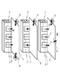
- FIG. 2 shows an example of spatial data when the transportation system is “train” and the boarding area is “station platform”.
- station platforms 701, 702, and 703 are platform platforms of different stations.
- an example of the spatial data related to the alignment simulation in the station platform 703 when the passenger gets on the train from the station platform 703 and gets off at the station platform 701 or 702 will be described.
- train doors 711, 714, 717 correspond to the boarding / alighting positions in the spatial data.
- Positions 718, 719 and 720 in front of the train door correspond to the alignment position 107.
- the ticket gate 708 and the stairs 707 correspond to the entrance to the boarding area (station platform).
- train doors 709, 712, and 715 correspond to the boarding / exiting positions in the spatial data.
- Stairs 704 and 705 correspond to the entrance from the boarding area.
- train doors 710, 713, 716 correspond to the boarding / exiting positions in the spatial data.
- Stairs 706 correspond to the entrance from the boarding area.
- a passenger who gets on the door 711 of the station platform 703 gets off the door 710 on the station platform 702 and gets off the door 709 on the station platform 701.
- these doors 709, 710, and 711 are collectively referred to as “boarding position A”.
- boarding position B The passenger who gets on the door 714 of the station platform 703 gets off the door 713 on the station platform 702 and gets off the door 712 on the station platform 701.
- these doors 712, 713, and 714 are collectively referred to as “boarding position B”.
- a passenger who gets on the door 717 of the station platform 703 gets off the door 716 on the station platform 702 and gets off the door 715 on the station platform 701.
- these doors 715, 716, and 717 are collectively referred to as “boarding position C”.
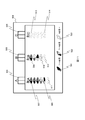
- Fig. 3 shows an example of spatial data when the transportation system is "Elevator” and the boarding area is “Elevator Hall”.
- elevator halls 901, 902, and 903 are elevator halls on different floors.
- an example of spatial data related to the alignment simulation in the elevator hall 903 when the passenger gets into the elevator car from the elevator hall 903 and gets off to the elevator hall 902 or 903 will be described.
- the elevator doors 911, 914, 917 correspond to the boarding / exiting positions in the spatial data. Positions 918, 919 and 920 in front of the elevator door correspond to the alignment position 107.
- the boundaries 907 and 908 correspond to entrances to the boarding area (elevator hall).
- elevator doors 909, 912, and 915 correspond to the boarding / alighting positions in the spatial data.
- the boundaries 904 and 905 correspond to the entrance from the boarding area.
- elevator doors 910, 913, 916 correspond to the boarding / exiting positions in the spatial data.
- a boundary 906 corresponds to the entrance from the boarding area.
- a passenger who gets on the door 911 of the elevator hall 903 gets off the door 910 in the elevator hall 902 and gets off the door 909 in the elevator hall 901.
- these doors 909, 910, and 911 are collectively referred to as a “boarding position A”.
- a passenger who gets on the door 914 of the elevator hall 903 gets off the door 913 in the elevator hall 902 and gets off the door 912 in the elevator hall 901.
- these doors 912, 913, and 914 are collectively referred to as “boarding position B”.
- a passenger who gets on the door 917 of the elevator hall 903 gets off the door 916 in the elevator hall 902 and gets off the door 915 in the elevator hall 901.
- these doors 915, 916, and 917 are collectively referred to as “boarding position C”.
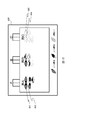
- FIG. 4 is an example in which the spatial data of FIGS. 2 and 3 is expressed as a network topology.
- the same network topology is used in FIGS. 2 and 3 for easy understanding.
- the network topology may be different depending on the object.
- Nodes 1008 and 1007 correspond to entrances to the boarding area.
- Nodes 1004, 1005, and 1006 correspond to entrances from the boarding area.
- Nodes 1018, 1019, and 1020 correspond to the alignment positions.
- Nodes 1009, 1012, 1015, 1010, 1013, and 1016 correspond to the getting on / off positions.
- Nodes 1009, 1010, and 1011 correspond to the boarding / alighting position A and are connected in terms of network topology.
- the nodes 1012, 1013, and 1014 correspond to the getting-on / off position B and are connected in a network topology.
- Nodes 1015, 1016, and 1017 correspond to the boarding / alighting position C and are connected in a network topology.
- the distance from the entrance to the alignment position or the boarding position may be called “access distance”, and the distance from the getting-off position to the entrance may be called “egress distance”.
- the distance from the node 1008 to the node 1018 or the distance from the node 1007 to the node 1020 is an access distance.
- the distance from the node 1010 to the node 1006 or the distance from the node 1012 to the node 1005 is an egress distance.
- the distance may be a linear distance or a moving distance of a passenger.
- FIG. 5 shows an example of the distance data table 109.
- the distance data table 109 may include an access distance and an egress distance.
- the distance data table 109 has information on the distance from each entrance / exit to each of the entry / exit positions 403, 404, and 405.
- the value “13” stored in the intersection column between the row of the entrance 1007 and the column of the entry / exit position A indicates that the access distance from the entrance 1007 to the entry / exit position (ride position) A is “13”. It is shown that.
- the value “12” stored in the column of the intersection of the row of the entry gate 1006 and the column of the entry / exit position B is “12” as the egress distance from the entry / exit position (alighting position) B to the entry point 1006. It is shown that.
- the unit of the value stored in the distance data table 109 may be a distance length, a travel time, or any other value.
- FIG. 6 shows an example of the passenger data table 105.
- the passenger data table 105 has information on the number of passengers traveling from each entrance to each exit on the transport system.
- the value “9 people” stored in the intersection column between the row of the entrance 1007 and the column of the entrance 1004 indicates that the number of passengers traveling from the entrance 1007 to the entrance 1004 on the transport system is “9”. It shows that it is a person.
- the processing of the alignment evaluation calculation unit 103 is preferably executed in parallel for each of the plurality of boarding positions.
- FIG. 7 shows an example of the parameter input form 200.
- the parameter input form 200 is a GUI (Graphical User Interface) for the user of the simulation apparatus 2 to input parameters related to the alignment behavior simulation.
- the parameter input form 200 may be generated by the parameter input unit 101.
- the parameter input form 200 may include items for inputting parameters related to transportation system data and parameters related to alignment behavior. Furthermore, the parameter input form 200 may have an item for inputting and editing the number of passengers in the passenger data table 105.
- the parameter input form 200 may have options for the type of transportation system. For example, the train 211 or the elevator 210 may be selected.
- the parameter input form 200 may have an input field for the capacity 201 of the transportation system.
- One entry field for the capacity 201 may be provided as shown in FIG. 7, or may be provided for each type of transportation system.
- the parameter input form 200 may have input fields for the alignment behavior parameter 102, an alignment width 202, an access distance coefficient 203, an egress distance coefficient 204, an alignment number coefficient 205, and a capacity coefficient 206.
- the alignment behavior parameter 102 may be used by the alignment evaluation calculation unit 103 to calculate the attractiveness for each alignment position.
- the alignment width 202 is a value indicating how many rows are aligned at the alignment position.
- the access distance coefficient 203 is a value for adjusting the magnitude that the access distance affects the attractiveness of each alignment position. The greater the access distance coefficient 203, the higher the attractiveness of the aligned position with the closer access distance.
- the egress distance coefficient 204 is a value for adjusting the size at which the egress distance affects the attractiveness of each alignment position. The greater the egress distance coefficient 204, the higher the attractiveness of the aligned position that is closer to the egress distance.
- the alignment number coefficient 205 is a coefficient for adjusting the size of the alignment number at the alignment position that affects the attractiveness of each alignment position. The greater the number of aligned people coefficient 205, the higher the attractiveness of the aligned positions with a smaller number of aligned people.
- the capacity coefficient 206 is a coefficient for adjusting the magnitude that affects the attractiveness of each alignment position when the number of aligned persons at the alignment position exceeds the capacity 201 of the transportation system. As the capacity factor 206 is larger, the attractiveness of the alignment position where the number of alignment members exceeds the capacity 201 may be calculated lower.
- FIG. 8 is a flowchart illustrating a processing example of the alignment evaluation calculation unit 103.
- the alignment evaluation calculation unit 103 extracts a plurality of passengers moving from each entrance to each exit from the passenger data table 105. Then, the alignment evaluation calculation unit 103 counts the number of passengers moving for each combination of entrance and exit. And the alignment evaluation calculation part 103 rearranges the extracted several passengers in arbitrary orders, and produces a passenger list. In the passenger list, passengers up to M (M is an integer equal to or greater than 1) are arranged in order from the first.
- the alignment evaluation calculation unit 103 assigns an initial value “1” to the variable i.
- the alignment evaluation calculation unit 103 acquires the i-th passenger p i from the passenger list.
- (S1405) aligned evaluation computing unit 103 calculates the attractiveness of each alignment position.
- the alignment evaluation calculation unit 103 calculates the attractiveness of each alignment position by the following equation (1).
- the FLOOR function is a function that rounds down a real number to an integer.
- Attractiveness 100 / (access distance x access distance coefficient + egress distance x egress distance coefficient + number of people in alignment x number of people in alignment + FLOOR (number of people in alignment / capacity) x capacity factor) ... (1)
- passenger attributes are the entrance and exit of the passenger. Passengers with different entrances may have different access distances to each boarding position. Passengers with different entry points may have different egress distances from each getting-off position. Passengers with different orders may have different numbers of people in each alignment position. In principle, it may be assumed that the alignment position with a small number of aligned persons has a shorter waiting time.
- a coefficient can be set for each parameter (for example, an access distance, an egress distance, and the number of aligned people) that affects the alignment behavior, and the attractiveness of each aligned position can be adjusted. Adjusting the attractiveness by setting a coefficient is also adjusting the influence on the alignment behavior. That is, according to the present embodiment, it is possible to easily execute the alignment behavior simulation of various patterns by changing the coefficient.
- (S1406) aligned evaluation computing unit 103 based on the attractiveness of each alignment position calculated in S1405, to determine the alignment position q passengers p i are aligned.
- the alignment position where the passengers align may be determined by other methods.
- the passenger's alignment position may be determined probabilistically according to the attractiveness of each alignment position.
- the above formula for calculating the attractiveness of this embodiment is defined such that the more attractive the alignment position is, the higher the attractiveness is.
- the attractiveness is defined so that the more attractive the alignment position is, the smaller the attractiveness is. May be.
- the alignment evaluation calculation unit 103 stores the value of i in the alignment list at the alignment position q. This is to record the process of changing the number of people on the line. In place of this process, the number of aligned persons may be simply recorded for each aligned position q.
- the alignment evaluation calculation unit 103 determines an alignment position for all passengers included in the passenger list (S1403: NO)
- the alignment evaluation unit 103 outputs an alignment list for each alignment position q and ends.
- an alignment list including information on which number of passengers are aligned at which alignment position is generated.
- FIG. 9 is a diagram for explaining a method for calculating the number of people arranged (processing in S1405).
- FIG. 9 shows the calculation of the number of aligned persons when information on the alignment behavior parameter (FIG. 7), the passenger data table 105 (FIG. 6), and the distance data table 109 (FIG. 5) is input to the alignment evaluation calculation unit 103. Show the process.
- the passenger 1101 stores information indicating the number of passengers.
- the attractiveness 1103 of the getting-on / off position (alignment position) A stores the attractiveness of the getting-on / off position A when the passenger 1101 enters the getting-on / off area (for example, a station platform or an elevator hall) from the entrance.
- the getting-on / off area for example, a station platform or an elevator hall
- the attractiveness 1104 of the getting-on / off position B stores the attractiveness of the getting-on / off position B when the passenger 1101 enters the getting-on / off area from the entrance.
- the attractiveness 1105 of the getting-on / off position C stores the attractiveness of the getting-on / off position C when the passenger 1101 enters the getting-on / off area from the entrance.
- the number of people arranged at the boarding / alighting position (alignment position) A stores the number of people at the boarding / alighting position A when the passenger 1101 enters the boarding / alighting area from the entrance.
- the number of people aligned at the getting-on / off position B 1107 stores the number of people arranged at the getting-on / off position B when the passenger 1101 enters the boarding / exiting area from the entrance.
- the number of people aligned at the getting-on / off position C stores the number of people arranged at the getting-on / off position C when the passenger 1101 enters the getting-on / off area from the entrance.
- the first passenger (passenger on line 1110) is a passenger scheduled to move from the entrance 1007 to the exit 1004. For this passenger, it is calculated that the attractiveness 1103 at the getting-on / off position A is “4.74”, the attractiveness 1104 at the getting-on / off position B is “4.20”, and the attractiveness 1105 at the getting-on / off position C is “3.39”. . In this case, the attractiveness of the alignment position A is the largest. Therefore, this first passenger adds “1” to the number of people 1106 at the boarding / alighting position A, assuming that they are aligned at the alignment position A.
- the second passenger (passenger on line 1111) is also a passenger scheduled to move from the entrance 1007 to the exit 1004. For this passenger, it is calculated that the attractiveness 1103 at the getting-on / off position A is “4.32”, the attractiveness 1104 at the getting-on / off position B is “4.20”, and the attractiveness 1105 at the getting-on / off position C is “3.39”. .
- the attractiveness of the alignment position A is slightly lower than that of the first passenger. This is because the first passenger has already been aligned at the alignment position A. However, the attractiveness of the alignment position A is still the largest. Therefore, assuming that the second passenger is also aligned with the alignment position A, “1” is added to the number of persons 1106 aligned at the boarding / exiting position A.
- the third passenger (passenger on line 1112) is also a passenger scheduled to move from the entrance 1007 to the exit 1004.
- the attractiveness 1103 at the getting-on / off position A is calculated as “4.15”
- the attractiveness 1104 at the getting-on / off position B is “4.20”
- the attractiveness at the getting-on / off position C is “3.39”.
- the attractiveness of the alignment position B is the largest. Therefore, this third passenger adds “1” to the number of people 1107 at the boarding / exiting position B, assuming that they are aligned at the alignment position B.
- each passenger is moving to the same entrance / exit, of course, it can simulate similarly when each passenger moves to a different entrance / exit. In that case, the attractiveness of each boarding / alighting position may differ depending on which entrance each passenger is scheduled to move from which entrance.
- FIG. 10 is a flowchart showing a processing example of the alignment result display unit 111. Note that the flowchart of FIG. 10 is an example of processing for one alignment position. Therefore, in an actual simulation, the process of FIG. 10 may be executed for each alignment position.
- the alignment result display unit 111 acquires the alignment list of the alignment position q.
- the alignment result display unit 111 assigns an initial value “1” to the variable j.
- the alignment result display unit 111 obtains the value v stored in the jth of the alignment list.
- the value v corresponds to the value i stored in the sorted list in S1407 of FIG. That is, the value v is a value indicating the number of the passenger 1101 in FIG. 9 that corresponds to the jth passenger in the sorted list.
- the alignment result display unit 111 determines a position where the j-th passenger at the alignment position q is drawn.
- the drawing position may be defined in advance or may be calculated by calculation.
- the alignment result display unit 111 may change the drawing color of the jth passenger according to the value v. What is changed according to the value v may be other than the color, for example, the display size or shape.
- the alignment result display part 111 draws a passenger with the determined color in the determined position.
- the simulation apparatus 2 may display a simulation execution screen as shown in FIG.
- FIG. 11 shows an example of a simulation execution screen in the case of the alignment width 202 “1”.
- the simulation execution screen may be generated by the alignment result display unit 111.
- the door 504 corresponds to the getting-on / off position A
- the door 505 corresponds to the getting-on / off position B
- the door 506 corresponds to the getting-on / off position C.
- row A in front of door 504 corresponds to alignment position A
- row B in front of door 505 corresponds to alignment position B
- row C in front of door 506 corresponds to alignment position C.
- Colored passengers between passengers 507 to 508 drawn in column A indicate passengers aligned at alignment position A at the current time of the simulation.
- the uncolored passenger 511 depicted in the column A indicates a passenger scheduled to be aligned at the alignment position A after the current time (that is, from now on).
- the colored passengers between the passengers 509 to 510 drawn in the row B indicate the passengers aligned at the alignment position B at the present time.
- Colorless passengers 512 drawn in column B indicate passengers scheduled to be aligned at alignment position B after the current time.
- Colorless passengers between passengers 513 to 514 depicted in column C indicate passengers scheduled to be aligned at alignment position C after the current time.
- Colorless passengers may be changed to colored passengers as the simulation progresses. For example, as the simulation progresses and more passengers line up at the alignment position A, the uncolored passenger 511 may change to a colored passenger. Similarly, if more passengers are aligned at the alignment position B, the colorless passenger 512 may change to a colored passenger. When the passenger is aligned at the alignment position C, the colorless passenger 513 may be changed to a colored passenger.
- the alignment result display unit 111 may display the number of passengers arranged in which alignment position according to the color density of the colored passengers, for example.
- the first to fourth passengers are expressed in the darkest color
- the fifth to eighth passengers are expressed in the second darkest color
- the eighth and subsequent passengers are expressed in the third darkest color.
- FIG. 12 shows an example of a simulation execution screen in the case of the alignment width 202 “2”.
- FIG. 12 is an example of a simulation execution screen when passengers line up in two rows at each of the getting-on / off positions A, B, and C.
- the second passenger 602 may be arranged in the row right next to the passenger 601.
- the user of the simulation apparatus 2 can easily simulate the alignment behavior of various patterns by adjusting the alignment behavior parameter (see FIG. 7).
- the alignment behavior parameter see FIG. 7
- the user of the simulation apparatus 2 can immediately confirm the adjustment result of the alignment behavior parameter. Thereby, even when the user does not have deep knowledge about the parameters regarding the alignment behavior, the alignment behavior can be easily simulated.
- Simulation device 101 Parameter input unit 102: Alignment action parameter 103: Alignment evaluation calculation unit 105: Passenger data table 106: Spatial data 109: Distance data table 111: Alignment result display unit
Abstract
輸送システムの整列行動に関するシミュレーションを容易にする。 輸送システムの乗客の整列行動をシミュレーションするシミュレーション装置は、各乗客が、乗車エリアにおいて輸送システムの複数の乗降口の何れか1つに整列して乗車し、降車エリアにおいて輸送システムのその乗車した乗降口から降車するシミュレーションを実行するにあたり、乗客が乗車エリアに到着したときの各乗降口の整列人数に基づいて当該乗客にとっての各乗降口の魅力度を算出し、その算出した魅力度に基づいて当該乗客が整列する乗降口を決定する。
Description
本発明は、整列行動のシミュレーションに関する。
駅のホームやビルのエレベーターホール等、大勢の人々が乗降する場所における混雑が課題となっている。駅やビルを混雑が緩和されるように設計したり、混雑緩和の対策を検討したりする場合、列車やエレベーター等、輸送システムの運行が乗客に与える影響と、乗客の行動が輸送システムに与える影響との両方を考慮する必要がある。すなわち、相互の影響を考慮する必要がある。
輸送システムの乗降場所における乗客の待機行動は、待ち時間及び混雑に大きな影響を与える。例えば、駅のホームの階段近くが混雑すると、階段から流入しようとする乗客の移動と、階段から流出しようする乗客の移動とが阻害されるため、待機行動の把握が重要となる。特に混雑時、乗客は整列して待機することが多い。この場合、整列の長さ及び/又は整列の形状によって、同じ待ち人数であっても、乗降時間が短縮したり、増大したりする。
特許文献1には、エレベーターを利用してビル内を移動する人の混雑について、エレベーターの運行と乗客の移動との相互影響を評価する人流演算装置が開示されている。
特許文献1は、エレベーターホールにおける人々の待機行動を、エレベーターのドアの位置と周囲の人の位置とに応じて分散することを前提としており、混雑時の整列行動を十分に考慮しているとは言えない。
また、待機行動は、乗客、場所及び時間帯等、環境の違いによって大きく異なる可能性が高いため、対象とする整列行動に応じて、各種パラメータを調整する必要があることも多い。しかしながら、整列行動についてあまり詳しくないユーザが、整列行動に関するパラメータを適切に設定することは難しい。
そこで本発明の目的は、輸送システムの整列行動に関するシミュレーションを容易に実施可能なシミュレーション装置、方法及びプログラムを提供することにある。
一実施例に係る、輸送システムの乗客の整列行動をシミュレーションするシミュレーション装置は、各乗客が、乗車エリアにおいて輸送システムの複数の乗降口の何れか1つに整列して乗車し、降車エリアにおいて輸送システムのその乗車した乗降口から降車するシミュレーションを実行するにあたり、乗客が乗車エリアに到着したときの各乗降口の整列人数に基づいて当該乗客にとっての各乗降口の魅力度を算出し、その算出した魅力度に基づいて当該乗客が整列する乗降口を決定する。
本発明によれば、輸送システムの整列行動に関するシミュレーションを容易に実施することができる。
以下、実施例を説明する。
以下の説明では、「xxxテーブル」、の表現にて情報を説明することがあるが、情報は、どのようなデータ構造で表現されていてもよい。すなわち、情報がデータ構造に依存しないことを示すために、「xxxテーブル」を「xxx情報」と呼ぶことができる。
以下の説明では、「プログラム」を主語として処理を説明する場合があるが、プログラムは、プロセッサ(例えばCPU(Central Processing Unit))によって実行されることで、定められた処理を、適宜に記憶資源(例えばメモリ)及び通信インターフェイスデバイスのうちの少なくとも1つを用いながら行うため、処理の主語が、プロセッサ、そのプロセッサを有する装置とされてもよい。プロセッサが行う処理の一部又は全部が、ハードウェア回路で行われてもよい。コンピュータプログラムは、プログラムソースからインストールされてよい。プログラムソースは、プログラム配布サーバ又は記憶メディア(例えば可搬型の記憶メディア)であってもよい。
以下の実施例において、要素の数等(個数、数値、量、範囲等を含む)に言及する場合、特に明示した場合及び原理的に明らかに特定の数に限定される場合などを除き、その特定の数に限定されるものではなく、特定の数以上でも以下でも良いものとする。
以下の実施例において、その構成要素(要素ステップなどを含む)は、特に明示した場合及び原理的に明らかに必須であると考えられる場合などを除き、必ずしも必須のものではない。
図1は、実施例に係るシミュレーション装置2の構成例を示す。
シミュレーション装置2は、機能として、パラメータ入力部101、整列評価演算部103、及び、整列結果表示部111を有する。これらの機能は、コンピュータプログラムとしてメモリ12に格納されてよい。メモリ12の例は、DRAM(Dynamic Random Access Memory)、ReRAM(Resistive Random Access Memory)、FeRAM(Ferroelectric Random Access Memory)である。
シミュレーション装置2は、データとして、整列行動パラメータ102、乗客データ105、輸送システムデータ110、及び、空間データ106を有する。空間データ106は、整列位置107、乗降位置108、及び、距離データ109に関する情報を含んで良い。これらのデータは、ストレージ装置14に格納されてよい。ストレージ装置14の例は、HDD(Hard Disk Drive)、SSD(Solid State Drive)である。CPU10は、メモリ12からコンピュータプログラムを読み出して実行することにより、各種機能を実現してよい。また、CPU10は、必要に応じて、ストレージ装置14に対して、データのリード及びライトを実行してよい。
パラメータ入力部101は、整列行動パラメータ102、乗客データ105、及び、輸送システムデータ110に関する入力を受け付ける。パラメータ入力部101に入力されるパラメータは、シミュレーション装置2のユーザから入力されても良いし、所定のファイルから読み込まれてもよい。
整列評価演算部103は、各乗客が、乗車エリアにおいて輸送システムの複数の乗降口(整列位置107又は乗降位置108)の何れか1つに整列して乗車し、降車エリアにおいて輸送システムのその乗車した乗降口から降車するシミュレーションを実行する。その際、整列評価演算部103は、乗客が乗車エリアに到着したときの各乗降口の整列人数に基づいて、当該乗客にとっての各乗降口の魅力度を算出し、その算出した魅力度に基づいて、当該乗客が整列する乗降口を決定する。
整列結果表示部111は、整列評価演算部103によって算出された各整列位置107における列長の段階的な変化を表示する。例えば、整列結果表示部111は、N(Nは1以上の整数)番目からN+k(kは0以上の整数)番目に整列した乗客と、他の乗客とを区別可能な態様で表示する。
図2は、輸送システムが「列車」、乗降エリアが「駅のホーム」の場合における空間データの例を示す。
図2において、駅のホーム701、702、703は、それぞれ別の駅のホームである。以下、乗客が、駅のホーム703から列車に乗車し、駅のホーム701又は702に降車する場合の、駅のホーム703における整列シミュレーションに係る空間データの一例を述べる。
駅のホーム703において、列車のドア711、714、717が、空間データにおける乗降位置に対応する。その列車のドアの手前の位置718、719、720が、整列位置107に対応する。改札口708および階段707が、乗降エリア(駅のホーム)への入場口に対応する。
駅のホーム701において、列車のドア709、712、715が、空間データにおける乗降位置に対応する。階段704及び705が、乗降エリアからの出場口に対応する。
駅のホーム702において、列車のドア710、713、716が、空間データにおける乗降位置に対応する。階段706が、乗降エリアからの出場口に対応する。
駅のホーム703のドア711から乗車した乗客は、駅のホーム702ではドア710から降車し、駅のホーム701ではドア709から降車する。実施例の説明において、これらのドア709、710、711をまとめて「乗降位置A」と呼ぶ。
駅のホーム703のドア714から乗車した乗客は、駅のホーム702ではドア713から降車し、駅のホーム701ではドア712から降車する。実施例の説明において、これらのドア712、713、714をまとめて「乗降位置B」と呼ぶ。
駅のホーム703のドア717から乗車した乗客は、駅のホーム702ではドア716から降車し、駅のホーム701ではドア715から降車する。実施例の説明において、これらのドア715、716、717をまとめて「乗降位置C」と呼ぶ。
図3は、輸送システムが「エレベーター」、乗降エリアが「エレベーターホール」の場合における空間データの例を示す。
図3において、エレベーターホール901、902、903は、それぞれ別の階のエレベーターホールである。以下、乗客が、エレベーターホール903からエレベーターのかごに乗車にし、エレベーターホール902又は903に降車する場合の、エレベーターホール903における整列シミュレーションに係る空間データの一例を述べる。
エレベーターホール903において、エレベーターのドア911、914、917が、空間データにおける乗降位置に対応する。そのエレベーターのドアの手前の位置918、919、920が、整列位置107に対応する。境界907及び908が、乗降エリア(エレベーターホール)への入場口に対応する。
エレベーターホール901において、エレベーターのドア909、912、915が、空間データにおける乗降位置に対応する。境界904、905が、乗降エリアからの出場口に対応する。
エレベーターホール902において、エレベーターのドア910、913、916が、空間データにおける乗降位置に対応する。境界906が、乗降エリアからの出場口に対応する。
エレベーターホール903のドア911から乗車した乗客は、エレベーターホール902ではドア910から降車し、エレベーターホール901ではドア909から降車する。実施例の説明において、これらのドア909、910、911をまとめて「乗降位置A」と呼ぶ。
エレベーターホール903のドア914から乗車した乗客は、エレベーターホール902ではドア913から降車し、エレベーターホール901ではドア912から降車する。実施例の説明において、これらのドア912、913、914をまとめて「乗降位置B」と呼ぶ。
エレベーターホール903のドア917から乗車した乗客は、エレベーターホール902ではドア916から降車し、エレベーターホール901ではドア915から降車する。実施例の説明において、これらのドア915、916、917をまとめて「乗降位置C」と呼ぶ。
図4は、図2及び図3の空間データをネットワークトポロジーとして表現した例である。
本実施例では、説明をわかりやすくするため、図2と図3を同じネットワークトポロジーとしている。しかし、対象の相違によってネットワークトポロジーは異なってよい。
ノード1008、1007は、乗降エリアへの入場口に対応する。ノード1004、1005,1006は、乗降エリアからの出場口に対応する。
ノード1018、1019、1020は、整列位置に対応する。ノード1009、1012、1015、1010、1013、1016は、乗降位置に対応する
ノード1009、1010、1011は、乗降位置Aに対応し、ネットワークトポロジー的に接続関係にある。ノード1012、1013、1014は、乗降位置Bに対応し、ネットワークトポロジー的に接続関係にある。ノード1015、1016、1017は、乗降位置Cに対応し、ネットワークトポロジー的に接続関係にある。
ネットワークトポロジーにおける、入場口から整列位置又は乗車位置までの距離を「アクセス距離」と呼び、降車位置から出場口までの距離を「イグレス距離」と呼んでもよい。例えば、ノード1008からノード1018までの距離、又は、ノード1007からノード1020までの距離は、アクセス距離である。例えば、ノード1010からノード1006までの距離、又は、ノード1012からノード1005までの距離は、イグレス距離である。距離は、直線距離であっても良いし、乗客の移動距離であってもよい。
図5は、距離データテーブル109の例を示す。距離データテーブル109は、アクセス距離、及び、イグレス距離を含んで良い。
距離データテーブル109は、各出入場口から各乗降位置403、404、405までの距離に関する情報を有する。
例えば、入場口1007の行と乗降位置Aの列との交点の欄に格納されている値「13」は、入場口1007から乗降位置(乗車位置)Aまでのアクセス距離が「13」であることを示している。
例えば、出場口1006の行と乗降位置Bの列との交点の欄に格納されている値「12」は、乗降位置(降車位置)Bから出場口1006までのイグレス距離が「12」であることを示している。
距離データテーブル109に格納される値の単位は、距離の長さであっても良いし、移動時間であっても良いし、それ以外であってもよい。
図6は、乗客データテーブル105の例を示す。
乗客データテーブル105は、各入場口から輸送システムに乗って各出場口まで移動する乗客数に関する情報を有する。
例えば、入場口1007の行と出場口1004の列との交点の欄に格納されている値「9人」は、入場口1007から輸送システムに乗って出場口1004まで移動する乗客数が「9人」であることを示している。
図6の例では、特定の乗降位置から乗車する移動のみが設定されているが、複数の乗降位置から乗車する移動が設定されてもよい。その場合、整列評価演算部103の処理は、複数の乗車位置のそれぞれについて、並列に実行されることが好ましい。
図7は、パラメータ入力フォーム200の一例を示す。
パラメータ入力フォーム200は、シミュレーション装置2のユーザが、整列行動シミュレーションに関するパラメータを入力するためのGUI(Graphical User Interface)である。パラメータ入力フォーム200は、パラメータ入力部101によって生成されてよい。
パラメータ入力フォーム200は、輸送システムデータに関するパラメータと、整列行動に関するパラメータとを入力するための項目を有してよい。さらに、パラメータ入力フォーム200は、乗客データテーブル105の乗客数を入力及び編集するための項目を有してもよい。
パラメータ入力フォーム200は、輸送システムの種類の選択肢を有してよい。例えば、列車211又はエレベーター210を選択できてよい。パラメータ入力フォーム200は、輸送システムの定員201の入力欄を有してよい。定員201の入力欄は、図7のように1つ設けられてもよいし、輸送システムの種類毎に設けられてもよい。
パラメータ入力フォーム200は、整列行動パラメータ102に関し、整列幅202、アクセス距離係数203、イグレス距離係数204、整列人数係数205、及び、定員係数206の入力欄を有してよい。
整列行動パラメータ102は、整列評価演算部103において整列位置毎の魅力度を算出するために使用されてよい。
整列幅202は、整列位置に何列で並ぶかを示す値である。
アクセス距離係数203は、アクセス距離が、各整列位置の魅力度に影響を与える大きさを調整するための値である。アクセス距離係数203が大きい程、アクセス距離の近い整列位置の魅力度が、高く算出されてよい。
イグレス距離係数204は、イグレス距離が、各整列位置の魅力度に影響を与える大きさを調整するための値である。イグレス距離係数204が大きい程、イグレス距離の近い整列位置の魅力度が、高く算出されてよい。
整列人数係数205は、整列位置の整列人数が、各整列位置の魅力度に影響を与える大きさを調整するための係数である。整列人数係数205が大きい程、整列人数の少ない整列位置の魅力度が、高く算出されてよい。
定員係数206は、整列位置の整列人数が輸送システムの定員201を超えたことが、各整列位置の魅力度に影響を与える大きさを調整するための係数である。定員係数206が大きい程、整列員数が定員201を超えている整列位置の魅力度が、低く算出されてよい。
図8は、整列評価演算部103の処理例を示すフローチャートである。
(S1401)整列評価演算部103は、乗客データテーブル105から、各入場口から各出場口まで移動する複数の乗客を抽出する。そして、整列評価演算部103は、入場口と出場口の組み合わせ毎の乗客の移動人数を集計する。そして、整列評価演算部103は、その抽出した複数の乗客を任意の順番に並び替え、乗客リストを作成する。乗客リストには、1番目から順にM(Mは1以上の整数)番目までの乗客が並んでいる。
(S1402)整列評価演算部103は、変数iに初期値「1」を代入する。
(S1403)整列評価演算部103は、変数iが乗客リスト長M以下の場合(S1403:YES)、S1404に進み、そうでない場合(S1403:NO)、S1409に進む。
(S1404)整列評価演算部103は、乗客リストから、i番目の乗客piを取得する。
(S1405)整列評価演算部103は、乗客piの属性と各整列位置の状況とに基づいて、各整列位置の魅力度を算出する。例えば、整列評価演算部103は、下記の式(1)によって各整列位置の魅力度を算出する。なお、FLOOR関数は、実数を整数に切り捨てる関数である。
魅力度=100/(アクセス距離×アクセス距離係数+イグレス距離×イグレス距離係数+整列人数×整列人数係数+FLOOR(整列人数/定員)×定員係数) …(1)
乗客の属性の例は、その乗客の入場口と出場口である。入場口が異なる乗客は、各乗車位置までのアクセス距離が異なり得る。出場口が異なる乗客は、各降車位置からのイグレス距離が異なり得る。順番が異なる乗客は、各整列位置における整列人数が異なり得る。なお、整列人数が少ない整列位置の方が、原則、待ち時間が少ないと仮定してよい。
乗客は、入場口から出場口までの移動時間(移動距離)ができるだけ短くなる経路を選ぶことが多いと考えられる。しかしこれは、環境、時間帯、乗客の嗜好や状態によって変化し得る。例えば、急いでいるときは、より短くなる経路を選び、急いでいないときは、多少時間がかかっても混雑していない経路を選んだり、暗い経路よりも明るい経路を選んだりすることが考えられる。そこで、本実施例は、整列行動に影響を与える各パラメータ(例えば、アクセス距離、イグレス距離、及び整列人数)に対して係数を設定可能とし、各整列位置の魅力度を調整可能としている。係数を設定して魅力度を調整することは、整列行動に対する影響を調整することでもある。すなわち、本実施例によれば、係数を変更することにより、様々なパターンの整列行動シミュレーションを容易に実行することができる。
(S1406)整列評価演算部103は、S1405で算出した各整列位置の魅力度に基づいて、乗客piが整列する整列位置qを決定する。本実施例では、乗客は、魅力度が最大の整列位置に整列するとする。しかし、他の方法で乗客が整列する整列位置を決定してもよい。例えば、乗客の整列位置を、各整列位置の魅力度に応じて確率的に決定してもよい。本実施例の上記の魅力度の算出式は、整列しやすい整列位置ほど魅力度が大きくなるように定義されているが、反対に、整列しやすい整列位置ほど魅力度が小さくなるように定義されてもよい。
(S1407)整列評価演算部103は、整列位置qの整列リストにiの値を格納する。整列人数の変化の過程を記録するためである。なお、この処理に代えて、整列位置q毎に単純に整列人数を記録してもよい。
(S1408)整列評価演算部103は、変数iに「1」を加算する。そして、整列評価演算部103は、S1403の処理に戻る。
(S1409)整列評価演算部103は、乗客リストに含まれる全乗客に対して整列位置を決定すると(S1403:NO)、各整列位置qの整列リストを出力して終了する。
以上の処理により、何番目の乗客が何れの整列位置に整列したのかに関する情報を含む整列リストが生成される。
図9は、整列人数の算出方法(S1405の処理)を説明するための図である。
図9の例は、整列行動パラメータ(図7)、乗客データテーブル105(図6)、距離データテーブル109(図5)の情報が整列評価演算部103に入力された場合における、整列人数の計算過程を示す。
乗客1101には、何番目の乗客であるかを示す情報が格納されている。
出入場口1102には、乗客1101の入場口と出場口とを示す情報が格納されている。
乗降位置(整列位置)Aの魅力度1103には、乗客1101が入場口から乗降エリア(例えば、駅のホームやエレベーターホール)に入場した時点における乗降位置Aの魅力度が格納されている。
乗降位置Bの魅力度1104には、乗客1101が入場口から乗降エリアに入場した時点における乗降位置Bの魅力度が格納されている。
乗降位置Cの魅力度1105には、乗客1101が入場口から乗降エリアに入場した時点における乗降位置Cの魅力度が格納されている。
乗降位置(整列位置)Aの整列人数1106には、乗客1101が入場口から乗降エリアに入場した時点における乗降位置Aの整列人数が格納されている。
乗降位置Bの整列人数1107には、乗客1101が入場口から乗降エリアに入場した時点における乗降位置Bの整列人数が格納されている。
乗降位置Cの整列人数1108には、乗客1101が入場口から乗降エリアに入場した時点における乗降位置Cの整列人数が格納されている。
1番目の乗客(行1110の乗客)は、入場口1007から出場口1004まで移動する予定の乗客である。この乗客にとって、乗降位置Aの魅力度1103が「4.74」、乗降位置Bの魅力度1104が「4.20」、乗降位置Cの魅力度1105が「3.39」と算出されたとする。この場合、整列位置Aの魅力度が最も大きい。そこで、この1番目の乗客は、整列位置Aに整列するとして、乗降位置Aの整列人数1106に「1」を加算する。
2番目の乗客(行1111の乗客)も、入場口1007から出場口1004まで移動する予定の乗客である。この乗客にとって、乗降位置Aの魅力度1103が「4.32」、乗降位置Bの魅力度1104が「4.20」、乗降位置Cの魅力度1105が「3.39」と算出されたとする。この場合、整列位置Aの魅力度は、1番目の乗客のときよりも少し低下している。整列位置Aに、1番目の乗客が既に整列しているからである。しかし、まだ整列位置Aの魅力度が最も大きい。そこで、この2番目の乗客も、整列位置Aに整列するとして、乗降位置Aの整列人数1106に「1」を加算する。
3番目の乗客(行1112の乗客)も、入場口1007から出場口1004まで移動する予定の乗客である。この乗客にとって、乗降位置Aの魅力度1103が「4.15」、乗降位置Bの魅力度1104が「4.20」、乗降位置Cの魅力度が「3.39」と算出されたとする。この場合、整列位置Bの魅力度が最も大きい。そこで、この3番目の乗客は、整列位置Bに整列するとして、乗降位置Bの整列人数1107に「1」を加算する。
行1113乃至1118に対しても同様の手順を実行することにより、各乗降位置の整列人数の変化をシミュレーションすることができる。
なお、図9の例では、各乗客が同じ出入場口に移動しているが、もちろん各乗客が異なる出入場口に移動する場合についても同様にシミュレーションすることができる。その場合、各乗降位置の魅力度は、各乗客が何れの入場口から何れの出場口に移動する予定であるかによって異なり得る。
図10は、整列結果表示部111の処理例を示すフローチャートである。なお、図10のフローチャートは、1つの整列位置に対する処理の例である。したがって、実際のシミュレーションでは、各整列位置に対して図10の処理を実行してよい。
(S1501)整列結果表示部111は、整列位置qの整列リストを取得する。
(S1502)整列結果表示部111は、変数jに初期値「1」を代入する。
(S1503)整列結果表示部111は、変数jが整列リスト長L(Lは1以上の整数)以下の場合(S1503:YES)、S1504へ進み、整列リストに含まれる全ての乗客について描画し終えた場合(S1503:NO)、本処理を終了する。
(S1504)整列結果表示部111は、整列リストのj番目に格納されている値vを取得する。値vは、図8のS1407において整列リストに格納された値iに相当する。すなわち、値vは、整列リストのj番目に対応する乗客が、図9の乗客1101の何番目であるかを示す値である。
(S1505)整列結果表示部111は、整列位置qのj番目の乗客を描画する位置を決定する。描画位置は、予め定義されてもよいし、計算によって算出されてもよい。整列結果表示部111は、値vに応じて、そのj番目の乗客の描画色を変更してよい。値vに応じて変更されるのは、色以外であっても良く、例えば、表示の大きさ又は形状などであってもよい。そして、整列結果表示部111は、その決定した位置に、その決定した色で、乗客を描画する。
(S1506)整列結果表示部111は、変数jに「1」を加算する。そして、整列結果表示部111は、S1503の処理に戻る。
以上の処理により、シミュレーション装置2は、例えば下記の図11又は図12のようなシミュレーション実行画面を表示してよい。
図11は、整列幅202「1」の場合のシミュレーション実行画面の一例を示す。シミュレーション実行画面は、整列結果表示部111によって生成されてよい。
図11において、ドア504は乗降位置Aに対応し、ドア505は乗降位置Bに対応し、ドア506は乗降位置Cに対応する。また、ドア504の前の列Aが整列位置Aに対応し、ドア505の前の列Bが整列位置Bに対応し、ドア506の前の列Cが整列位置Cに対応する。
列Aに描画されている乗客507から508までの間の色付き乗客は、シミュレーションの現時点において整列位置Aに整列している乗客を示す。列Aに描画されている色無し乗客511は、当該現時点以降に(すなわちこれから)整列位置Aに整列する予定の乗客を示す。
同様に、列Bに描画されている乗客509から510までの間の色付き乗客は、当該現時点において整列位置Bに整列している乗客を示す。列Bに描画されている色無し乗客512は、当該現時点以降に整列位置Bに整列する予定の乗客を示す。
列Cに描画されている乗客513から514までの間の色無し乗客は、当該現時点以降に整列位置Cに整列する予定の乗客を示す。
色無し乗客は、シミュレーションが進むにつれて、色付き乗客に変更されてよい。例えば、シミュレーションが進み、整列位置Aにさらに乗客が整列すると、色無し乗客511が色付き乗客に変わってよい。同様に、整列位置Bにさらに乗客が整列すると、色無し乗客512が色付き乗客に変わってよい。整列位置Cに乗客が整列すると、色無し乗客513が色付き乗客に変わってよい。
整列結果表示部111は、例えば、色付き乗客の色の濃さにより、何番目の乗客が何れの整列位置に並んだのかを区別可能な態様で表示してもよい。図11では、1番目から4番目の乗客を最も濃い色で、5番目から8番目の乗客を2番目に濃い色で、8番目以降の乗客を3番目に濃い色で表現している。これにより、シミュレーションが進んだ後も、何番目の乗客が何れの整列位置に並んだのかを一目で把握することができる。
図12は、整列幅202「2」の場合のシミュレーション実行画面の一例を示す。
図12は、各乗降位置A、B、Cに、乗客が2列で整列する場合のシミュレーション実行画面の例である。2列の場合、図12のように、1番目の乗客601が列Aの左の列に並んだ後、2番目の乗客602がその乗客601の右隣の列に並ぶとしてよい。
本実施例によれば、シミュレーション装置2のユーザは、整列行動パラメータ(図7参照)を調整することにより、様々なパターンの整列行動を容易にシミュレーションすることができる。また、各整列位置に整列する乗客の人数および整列の形状を、段階的な変化で描画することにより、シミュレーション装置2のユーザは、整列行動パラメータの調整結果を直ちに確認することができる。これにより、ユーザが、整列行動に関するパラメータについて深い知識を有さない場合であっても、容易に整列行動のシミュレーションを行うことができる。
上述した実施例は、本発明の説明のための例示であり、本発明の範囲を実施例にのみ限定する趣旨ではない。当業者は、本発明の要旨を逸脱することなしに、他の様々な態様で本発明を実施することができる。
2:シミュレーション装置 101:パラメータ入力部 102:整列行動パラメータ 103:整列評価演算部 105:乗客データテーブル 106:空間データ 109:距離データテーブル 111:整列結果表示部
Claims (9)
- 輸送システムの乗客の整列行動をシミュレーションするシミュレーション装置であって、プロセッサとメモリとを有し、
前記プロセッサは、
各乗客が、乗車エリアにおいて輸送システムの複数の乗降口の何れか1つに整列して乗車し、降車エリアにおいて輸送システムのその乗車した乗降口から降車するシミュレーションを実行するにあたり、
乗客が前記乗車エリアに到着したときの各乗降口の整列人数に基づいて、当該乗客にとっての各乗降口の魅力度を算出し、
その算出した魅力度に基づいて、当該乗客が整列する乗降口を決定する
シミュレーション装置。 - 前記乗車エリアは複数の入場口を有し、
前記プロセッサは、
さらに、前記乗客が到着した前記乗車エリアの入場口から各乗降口までのアクセス距離に基づいて、前記乗客にとっての各乗降口の魅力度を算出する
請求項1に記載のシミュレーション装置。 - 前記降車エリアは複数の出場口を有し、
前記プロセッサは、
さらに、前記乗客が降車する乗降口から前記降車エリアの前記乗客が向かう出場口までのイグレス距離に基づいて、前記乗客にとっての各乗降口の魅力度を算出する
請求項2に記載のシミュレーション装置。 - 前記プロセッサは、
前記整列人数、前記アクセス距離、及び、前記イグレス距離のそれぞれの前記魅力度に対する重み付け値を設定させるユーザインタフェースを出力する
請求項3に記載のシミュレーション装置。 - 前記プロセッサは、
各乗客が各乗降口に整列する過程を出力するにあたり、
n(nは1以上の整数)番目からn+k(kは0以上の整数)番目に整列した乗客と、他の乗客とを区別可能な態様で出力する
請求項1に記載のシミュレーション装置。 - 前記輸送システムは、エレベーターに係るシステムであり、
前記乗降口は、前記エレベーターのかごのドアであり、
前記乗車エリアは、前記かごの乗車階のエリアであり、
前記降車エリアは、前記かごの降車階のエリアである
請求項1に記載のシミュレーション装置。 - 前記輸送システムは、列車に係るシステムであり、
前記乗降口は、前記列車のドアであり、
前記乗車エリアは、前記列車の乗車駅のエリアであり、
前記降車エリアは、前記列車の降車駅のエリアである
請求項1に記載のシミュレーション装置。 - 輸送システムの乗客の整列行動をシミュレーションする方法であって、
プロセッサが、
各乗客が、乗車エリアにおいて輸送システムの複数の乗降口の何れか1つに整列して乗車し、降車エリアにおいて輸送システムのその乗車した乗降口から降車するシミュレーションを実行するにあたり、
乗客が前記乗車エリアに到着したときの各乗降口の整列人数に基づいて、当該乗客にとっての各乗降口の魅力度を算出し、
その算出した魅力度に基づいて、当該乗客が整列する乗降口を決定する
シミュレーション方法。 - 輸送システムの乗客の整列行動をシミュレーションするシミュレーション装置に、
各乗客が、乗車エリアにおいて輸送システムの複数の乗降口の何れか1つに整列して乗車し、降車エリアにおいて輸送システムのその乗車した乗降口から降車するシミュレーションを実行するにあたり、
乗客が前記乗車エリアに到着したときの各乗降口の整列人数に基づいて、当該乗客にとっての各乗降口の魅力度を算出し、
その算出した魅力度に基づいて、当該乗客が整列する乗降口を決定する
ことを実行させるためのコンピュータプログラム。
Priority Applications (2)
| Application Number | Priority Date | Filing Date | Title |
|---|---|---|---|
| SG11201809894UA SG11201809894UA (en) | 2016-05-18 | 2017-02-28 | Simulation apparatus, simulation method, and computer program |
| JP2018518108A JP6754831B2 (ja) | 2016-05-18 | 2017-02-28 | シミュレーション装置、方法、及びコンピュータプログラム |
Applications Claiming Priority (2)
| Application Number | Priority Date | Filing Date | Title |
|---|---|---|---|
| JP2016099271 | 2016-05-18 | ||
| JP2016-099271 | 2016-05-18 |
Publications (1)
| Publication Number | Publication Date |
|---|---|
| WO2017199532A1 true WO2017199532A1 (ja) | 2017-11-23 |
Family
ID=60325909
Family Applications (1)
| Application Number | Title | Priority Date | Filing Date |
|---|---|---|---|
| PCT/JP2017/007887 WO2017199532A1 (ja) | 2016-05-18 | 2017-02-28 | シミュレーション装置、方法、及びコンピュータプログラム |
Country Status (3)
| Country | Link |
|---|---|
| JP (1) | JP6754831B2 (ja) |
| SG (1) | SG11201809894UA (ja) |
| WO (1) | WO2017199532A1 (ja) |
Cited By (5)
| Publication number | Priority date | Publication date | Assignee | Title |
|---|---|---|---|---|
| WO2020026538A1 (ja) * | 2018-07-31 | 2020-02-06 | 株式会社日立製作所 | マルチカーエレベーターシステム及び建築構造物 |
| WO2020148881A1 (ja) * | 2019-01-18 | 2020-07-23 | 三菱電機株式会社 | 情報提示装置、情報提示システム、情報提示方法、及び情報提示プログラム |
| WO2021131332A1 (ja) | 2019-12-26 | 2021-07-01 | 株式会社日立製作所 | 建築モデルデータ支援システムおよび建築モデルデータ支援方法 |
| CN113423658A (zh) * | 2019-04-12 | 2021-09-21 | 三菱电机大楼技术服务株式会社 | 电梯装置 |
| CN114644266A (zh) * | 2020-12-18 | 2022-06-21 | 三菱电机株式会社 | 电梯系统 |
Citations (4)
| Publication number | Priority date | Publication date | Assignee | Title |
|---|---|---|---|---|
| JPH11217164A (ja) * | 1998-02-03 | 1999-08-10 | Hitachi Ltd | エレベーターのシミュレータ装置 |
| JP2005242595A (ja) * | 2004-02-25 | 2005-09-08 | Nec Corp | 公共交通機関情報提供システム |
| JP2008062729A (ja) * | 2006-09-06 | 2008-03-21 | Railway Technical Res Inst | プログラム及びシミュレーション装置 |
| JP2013073396A (ja) * | 2011-09-27 | 2013-04-22 | Hitachi Ltd | 車両混雑状況予測システム |
-
2017
- 2017-02-28 SG SG11201809894UA patent/SG11201809894UA/en unknown
- 2017-02-28 JP JP2018518108A patent/JP6754831B2/ja active Active
- 2017-02-28 WO PCT/JP2017/007887 patent/WO2017199532A1/ja active Application Filing
Patent Citations (4)
| Publication number | Priority date | Publication date | Assignee | Title |
|---|---|---|---|---|
| JPH11217164A (ja) * | 1998-02-03 | 1999-08-10 | Hitachi Ltd | エレベーターのシミュレータ装置 |
| JP2005242595A (ja) * | 2004-02-25 | 2005-09-08 | Nec Corp | 公共交通機関情報提供システム |
| JP2008062729A (ja) * | 2006-09-06 | 2008-03-21 | Railway Technical Res Inst | プログラム及びシミュレーション装置 |
| JP2013073396A (ja) * | 2011-09-27 | 2013-04-22 | Hitachi Ltd | 車両混雑状況予測システム |
Cited By (7)
| Publication number | Priority date | Publication date | Assignee | Title |
|---|---|---|---|---|
| WO2020026538A1 (ja) * | 2018-07-31 | 2020-02-06 | 株式会社日立製作所 | マルチカーエレベーターシステム及び建築構造物 |
| WO2020148881A1 (ja) * | 2019-01-18 | 2020-07-23 | 三菱電機株式会社 | 情報提示装置、情報提示システム、情報提示方法、及び情報提示プログラム |
| JPWO2020148881A1 (ja) * | 2019-01-18 | 2021-03-11 | 三菱電機株式会社 | 情報提示装置、情報提示システム、情報提示方法、及び情報提示プログラム |
| CN113423658A (zh) * | 2019-04-12 | 2021-09-21 | 三菱电机大楼技术服务株式会社 | 电梯装置 |
| CN113423658B (zh) * | 2019-04-12 | 2022-09-27 | 三菱电机楼宇解决方案株式会社 | 电梯装置 |
| WO2021131332A1 (ja) | 2019-12-26 | 2021-07-01 | 株式会社日立製作所 | 建築モデルデータ支援システムおよび建築モデルデータ支援方法 |
| CN114644266A (zh) * | 2020-12-18 | 2022-06-21 | 三菱电机株式会社 | 电梯系统 |
Also Published As
| Publication number | Publication date |
|---|---|
| JPWO2017199532A1 (ja) | 2019-01-17 |
| JP6754831B2 (ja) | 2020-09-16 |
| SG11201809894UA (en) | 2018-12-28 |
Similar Documents
| Publication | Publication Date | Title |
|---|---|---|
| WO2017199532A1 (ja) | シミュレーション装置、方法、及びコンピュータプログラム | |
| Li et al. | Behavioral effect on pedestrian evacuation simulation using cellular automata | |
| Ezaki et al. | Simulation of space acquisition process of pedestrians using proxemic floor field model | |
| Kuligowski et al. | A review of building evacuation models | |
| Borrmann et al. | Bidirectional coupling of macroscopic and microscopic pedestrian evacuation models | |
| Hassannayebi et al. | A hybrid simulation model of passenger emergency evacuation under disruption scenarios: A case study of a large transfer railway station | |
| JP6585285B2 (ja) | 人流評価システム、人流制御の検討方法 | |
| Eng Aik et al. | Simulating evacuations with obstacles using a modified dynamic cellular automata model | |
| Stubenschrott et al. | A dynamic pedestrian route choice model validated in a high density subway station | |
| Yuen et al. | An intelligence-based route choice model for pedestrian flow in a transportation station | |
| Tang et al. | Modeling and simulation of pedestrian flow in university canteen | |
| Liu et al. | Simulation of passenger motion in metro stations during rush hours based on video analysis | |
| Ji-hua et al. | A research of pedestrian evacuation simulation for BRT station based on fine grid method | |
| Biedermann et al. | A hybrid and multiscale approach to model and simulate mobility in the context of public events | |
| Liu et al. | Microscopic Simulation-Based Pedestrian Distribution Service Network in Urban Rail Station | |
| Fernandez et al. | Microscopic simulation of transit operations: policy studies with the MISTRANSIT application programming interface | |
| Hartmann et al. | Dynamic medium scale navigation using dynamic floor fields | |
| Qu et al. | Modeling pedestrian behaviors of boarding and alighting dynamics in urban railway stations | |
| Kuligowski | The evaluation of a performance-based design process for a hotel building: The comparison of two egress models | |
| Zhen et al. | Train rescheduling model with train delay and passenger impatience time in urban subway network | |
| Usher et al. | Simulation of pedestrian behavior in intermodal facilities | |
| WO2019087730A1 (ja) | ビル内交通予測システム、ビル内交通予測システムにおけるエレベーター乗り場レイアウトの生成方法及びプログラム | |
| Hermant | Video data collection method for pedestrian movement variables & development of a pedestrian spatial parameters simulation model for railway station environments | |
| Gao et al. | Hybrid dynamic route planning model for pedestrian microscopic simulation at subway station | |
| Kuusinen et al. | People flow in buildings: accurate modeling of how people use elevators and behave in emergencies is the key to successful people flow planning. |
Legal Events
| Date | Code | Title | Description |
|---|---|---|---|
| WWE | Wipo information: entry into national phase |
Ref document number: 2018518108 Country of ref document: JP |
|
| NENP | Non-entry into the national phase |
Ref country code: DE |
|
| 121 | Ep: the epo has been informed by wipo that ep was designated in this application |
Ref document number: 17798969 Country of ref document: EP Kind code of ref document: A1 |
|
| 122 | Ep: pct application non-entry in european phase |
Ref document number: 17798969 Country of ref document: EP Kind code of ref document: A1 |