WO2017195568A1 - 端子 - Google Patents
端子 Download PDFInfo
- Publication number
- WO2017195568A1 WO2017195568A1 PCT/JP2017/015992 JP2017015992W WO2017195568A1 WO 2017195568 A1 WO2017195568 A1 WO 2017195568A1 JP 2017015992 W JP2017015992 W JP 2017015992W WO 2017195568 A1 WO2017195568 A1 WO 2017195568A1
- Authority
- WO
- WIPO (PCT)
- Prior art keywords
- wall
- contact
- terminal
- contacts
- main body
- Prior art date
- Legal status (The legal status is an assumption and is not a legal conclusion. Google has not performed a legal analysis and makes no representation as to the accuracy of the status listed.)
- Ceased
Links
Images



Classifications
-
- H—ELECTRICITY
- H01—ELECTRIC ELEMENTS
- H01R—ELECTRICALLY-CONDUCTIVE CONNECTIONS; STRUCTURAL ASSOCIATIONS OF A PLURALITY OF MUTUALLY-INSULATED ELECTRICAL CONNECTING ELEMENTS; COUPLING DEVICES; CURRENT COLLECTORS
- H01R13/00—Details of coupling devices of the kinds covered by groups H01R12/70 or H01R24/00 - H01R33/00
- H01R13/02—Contact members
- H01R13/10—Sockets for co-operation with pins or blades
- H01R13/11—Resilient sockets
Definitions
- the technology disclosed in this specification relates to a terminal.
- a female terminal fitting described in, for example, Japanese Patent Application Laid-Open No. 2001-210417 (Patent Document 1 below) is known.
- This female terminal fitting has a main body formed in a rectangular box shape elongated in the front-rear direction.
- a tongue piece is formed to extend from the tip of the bottom wall of the main body, and this tongue piece is folded back into a mountain shape into the main body to form an elastic contact piece.
- an elongated bead is formed in the front-rear direction on the ceiling plate of the main body.
- the elastic contact piece presses the back surface of the tab from below, and accordingly, the surface of the tab is pressed against the bead.
- the central portion in the length direction of the bead is formed to be curved in an arc shape so as to escape upward, and both ends of the curved portion are protruding portions. Therefore, the surface of the tab is pressed against the two protruding portions at the front and rear.
- each bead is provided with a pair of protrusions, the surface of the tab is ideally pressed against the four protrusions.
- the height of the bead has a certain degree of variation, so that the bead does not necessarily contact at four places, and only three of the four places come into contact. In this case, the position of the contact with the tab of the male terminal fitting is not clearly determined, which is not preferable from the viewpoint of electrical connection.
- the terminal disclosed by this specification has a 1st wall part and the 2nd wall part arrange
- the mating terminal when the mating terminal is fitted in the main body, the mating terminal is sandwiched between the first contact of the elastic contact piece and the three second contacts on the second wall side. Become. At this time, since the first contact is located inside a triangle formed by connecting the three second contacts, a three-point contact in which the counterpart terminal contacts the three second contacts by the force received from the first contact. , The contact position becomes clear.
- the two-point contact is in an unstable state, and inevitably tries to return from an unstable state to a stable state. Therefore, it returns to the three-point contact again. As a result, the wobbling of the counterpart terminal can be eliminated.
- the terminal disclosed by this specification is good also as the following structures.
- the main body portion includes a third wall portion that connects one side edge of the first wall portion and one side edge of the second wall portion, and at least one of the two second contacts.
- the second contact point may be arranged closer to the third wall portion. According to such a configuration, since the separation distance between the second contact and the first contact disposed closer to the third wall portion can be increased, the rotational moment required to rotate the mating terminal increases, and the mating terminal It becomes easy to prevent the wobble itself.
- the main body has a fourth wall connecting the other side edge of the first wall and the other side edge of the second wall, and at least one of the second contacts
- the second contact may be arranged closer to the fourth wall. According to such a configuration, since the separation distance between the second contact and the first contact disposed closer to the fourth wall portion can be increased, the rotational moment required to rotate the mating terminal increases, and the mating terminal It becomes easy to prevent the wobble itself.
- the contact position with the mating terminal can be clarified and the wobbling of the mating terminal can be eliminated.
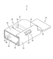
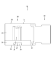
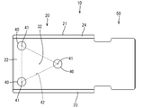
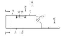
- Terminal perspective view Terminal plan Bottom view of terminals Terminal side view
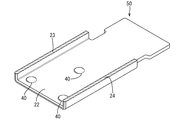
- the terminal 10 includes a terminal connection portion 20 connected to the mating terminal 60 and a wire connection portion 50 provided continuously behind the terminal connection portion 20.
- the terminal 10 is a female terminal, and a mating terminal 60 that is a male terminal having a flat tab shape can be fitted into the terminal connecting portion 20 and can be connected.
- the connecting direction of the terminal 10 and the mating terminal 60 is the front-rear direction
- the side to which the mating terminal 60 is connected is the front side
- the vertical and horizontal directions will be described with reference to FIG.
- the electric wire connecting portion 50 has a flat plate shape, and a core wire (not shown) can be welded to the upper surface of the electric wire connecting portion 50 by welding means such as resistance welding.
- the core wire of the electric wire is connected to the electric wire connecting portion 50 by welding, but the electric wire core wire may be connected to the electric wire connecting portion by crimping.
- the terminal connection portion 20 has a main body portion 21 having a rectangular tube shape as a whole.
- the main body 21 includes a bottom wall 22, a left side wall 23 configured to rise upward from the left side edge of the bottom wall 22, a right side wall 24 configured to rise upward from the right side edge of the bottom wall 22, and the left side wall 23
- a ceiling wall 25 extending rightward from the upper edge and an opening preventing wall 26 extending leftward from the upper edge of the right wall 24 along the upper surface of the ceiling wall 25 are configured.
- the left side wall 23 connects the left side edge of the bottom wall 22 and the left side edge of the ceiling wall 25
- the right side wall 24 connects the right side edge of the bottom wall 22 and the right side edge of the ceiling wall 25.
- the opening prevention wall 26 prevents the ceiling wall 25 from opening upward by pressing the right end of the ceiling wall 25 from above.
- a locking hole 27 is provided at the corner of the opening prevention wall 26 and the right side wall 24.
- a locking piece 28 provided at the right end of the ceiling wall 25 is fitted in the locking hole 27. Since the locking piece 28 is locked to the hole edge of the locking hole 27, the ceiling wall 25 is prevented from moving in the front-rear direction.
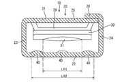
- the ceiling wall 25 is positioned above the bottom wall 22, and the ceiling wall 25 and the bottom wall 22 are arranged in parallel so as to face each other. A part of the ceiling wall 25 protrudes downward, and this protruding portion is an excessive deflection preventing portion 29.
- the excessive deflection preventing portion 29 serves to prevent the elastic contact piece 30 described below from being excessively bent toward the ceiling wall 25 and plastically deforming. If the elastic contact piece 30 tries to bend excessively, the upper surface of the elastic contact piece 30 comes into contact with the lower surface of the excessive deflection preventing portion 29 in a surface contact state, so that even if a strong force is applied, the force is dispersed over a wide range. It is possible to prevent the elastic contact piece 30 from being excessively bent.
- the elastic contact piece 30 is folded back into the main body portion 21 from the rear edge of the ceiling wall 25 and extends forward.
- the elastic contact piece 30 has a substantially mountain shape as a whole, and a first contact 31 is provided on the lower end portion of the elastic contact piece 30 so as to protrude downward.
- the first contact 31 is located near the front end of the elastic contact piece 30 and is located slightly in front of the above-described excessive deflection preventing portion 29.
- the elastic contact piece 30 can be displaced in a direction in which the first contact 31 is separated from the bottom wall 22 by the first contact 31 riding on the upper surface of the counterpart terminal 60 when the counterpart terminal 60 is inserted into the main body 21. It is said that.
- Both the elastic contact piece 30 and the excessive deflection preventing portion 29 are formed over substantially the entire width of the ceiling wall 25 as shown in FIG. For this reason, when the elastic contact piece 30 contacts the excessive deflection preventing portion 29, the elastic contact piece 30 contacts the excessive deflection preventing portion 29 over the entire width. Thereby, for example, when the mating terminal 60 enters the main body portion 21 in an oblique direction, the elastic contact piece 30 can be prevented from being pushed upward and plastically deformed.
- three second contacts 40 having a hemispherical shape are provided on the bottom wall 22 so as to protrude upward.
- the second contact 40 is disposed so as to be positioned at each vertex of the equilateral triangle.
- the two second contacts 40 are located on the front end side of the bottom wall 22 and are arranged side by side in the left-right direction.
- the second contact 40 located on the left side of the pair of second contacts 40 located on the front side is disposed near the left side wall 23, and the second contact 40 located on the right side is disposed near the right side wall 24. It is installed.
- one second contact 40 located on the rear side among the three second contacts 40 is located substantially at the center of the bottom wall 22.
- the second contact 40 on the rear side is located in the middle of the two second contacts 40 on the front side in the left-right direction.
- the region FR1 occupying the first contact 31 in the front-rear direction is the region FR2 from the front end of the second contact 40 located on the front side to the rear end of the second contact 40 located on the rear side. It is supposed to be located within the range.
- FIG. 8 when the mating terminal 60 is pushed down when the mating terminal 60 is inserted into the main body 21 and the first contact 31 rides on the top surface of the mating terminal 60. This means that the terminal 60 is supported by two second contacts 40 at the front and rear. In this way, even if the front end of the mating terminal 60 is tilted upward or downward, the wobbling of the mating terminal 60 can be eliminated because it is corrected to the original horizontal attitude.
- the region LR1 occupying the left and right direction of the first contact 31 is within the range of the region LR2 from the left end of the second contact 40 located on the left side to the right end of the second contact 40 located on the right side. It is supposed to be located in As shown in FIG. 10, when the mating terminal 60 is pushed downward when the mating terminal 60 is inserted into the main body 21 and the first contact 31 rides on the upper surface of the mating terminal 60, This means that the terminal 60 is supported by the second contacts 40 at the two left and right positions. In this way, even if the left end of the mating terminal 60 is tilted upward or downward (or the right end of the mating terminal 60 is tilted upward or downward), the original horizontal posture is corrected. The wobbling of the mating terminal 60 can be eliminated.
- the point indicated by reference numeral 32 is a point obtained by projecting the apex 32 of the first contact 31 onto the bottom wall 22 side, and is hereinafter referred to as a projection point 33.
- a broken line indicated by reference numeral 42 is a triangle connecting the vertices 41 of the three second contacts 40.
- the projection point 32 is located inside the triangle 42, and the first contact 31 is disposed so as to take such a position. Further, when the counterpart terminal 60 is inserted into the main body 21 and the first contact 31 rides on the upper surface of the counterpart terminal 60, the position of the projection point 32 moves slightly forward and is positioned approximately at the center of the triangle 42. It is like that.
- the mating terminal 60 when the mating terminal 60 is pushed into the bottom wall 22 by the force received from the first contact 31, the mating terminal 60 is necessarily supported by the three second contacts 40. For this reason, the counterpart terminal 60 is always elastically sandwiched between the apex 32 of the first contact 31 and the apexes 41 of the three second contacts 40, and the contact position can be clarified. .
- the mating terminal 60 when the mating terminal 60 is fitted in the main body 21, the first contact 31 of the elastic contact piece 30 and the three second contacts on the second wall (bottom wall 22) side.
- the counterpart terminal 60 is sandwiched between the terminal 40 and the terminal 40.
- the mating terminal 60 contacts the three second contacts 40 by the force received from the first contact 31.
- the contact point position becomes clear.
- the two-point contact is in an unstable state, and inevitably changes from an unstable state to a stable state. Since it tries to return, it will return to a three-point contact again. As a result, the wobbling of the mating terminal 60 can be eliminated.
- the main body 21 has a third wall (left wall 23) that connects one side edge of the first wall (left edge of the ceiling wall 25) and one side edge of the second wall (left edge of the bottom wall 22). ) And at least one second contact 40 of the three second contacts 40 may be disposed closer to the third wall portion. According to such a configuration, the distance between the second contact 40 and the first contact 31 disposed closer to the third wall can be increased, so that the rotational moment necessary to rotate the mating terminal 60 increases. It becomes easy to prevent wobbling of the counterpart terminal 60 itself.
- the main body 21 has a fourth wall (the right side wall 24) that connects the other side edge (the right side edge of the ceiling wall 25) of the first wall part and the other side edge (the right side edge of the bottom wall 22) of the second wall part. ) And at least one second contact 40 of the three second contacts 40 may be disposed closer to the fourth wall portion. According to such a configuration, the separation distance between the second contact 40 and the first contact 31 disposed closer to the fourth wall can be increased, so that the rotational moment required to rotate the mating terminal 60 is increased. It becomes easy to prevent wobbling of the counterpart terminal 60 itself.
- the technology disclosed in the present specification is not limited to the embodiments described with reference to the above description and drawings, and includes, for example, the following various aspects.
- the rectangular cylindrical main body portion 21 including four wall portions is illustrated, but other forms may be used as long as the main body portion includes the first wall portion and the second wall portion. It is good also as a rectangular tube-shaped main-body part which consists of two wall parts.
- two second contacts 40 are arranged on the front side, one second contact is arranged on the front side, and the remaining two second contacts are arranged. It may be arranged on the rear side.
- one second contact 40 of the three second contacts 40 is disposed closer to the left side wall 23, but two second contacts may be disposed closer to the left side wall 23. Good.
- one second contact 40 of the three second contacts 40 is disposed closer to the right side wall 24, but two second contacts may be disposed closer to the right side wall 24. Good.
- the elastic contact piece 30 is provided so as to be folded back from the rear edge of the ceiling wall 25 into the main body 21.
- a piece may be provided, or an elastic contact piece may be provided on the bottom wall 22 side.
Landscapes
- Details Of Connecting Devices For Male And Female Coupling (AREA)
Abstract
本明細書によって開示される端子10は、第1壁部(天井壁25)と前記第1壁部に対向して配設された第2壁部(底壁22)とを有し、全体として角筒形をなす本体部21と、前記第1壁部の前縁もしくは後縁から前記本体部21内に延出され、前記第2壁部側に突出して設けられた第1接点31を有し、前記第1接点31が前記第2壁部から離間する方向に変位可能とされた弾性接触片30と、前記第2壁部から前記第1壁部側に突出して3箇所設けられ、半球形状をなす3つの第2接点40とを備え、前記第1接点31は、前記第2壁部側に投影させた場合に、3つの前記第2接点40を結んで形成される三角形42の内部に位置するように配設されている構成とした。
Description
本明細書によって開示される技術は、端子に関する。
従来、角筒状をなす本体部の内部にビードとバネとが設けられた端子として、例えば特開2001-210417号公報(下記特許文献1)に記載の雌端子金具が知られている。この雌端子金具は、前後方向に細長い角形の箱状に形成された本体部を有している。本体部の底壁の先端からは、舌片が延出して形成され、この舌片が本体部内に向けて山形状に折り返されることで、弾性接触片が形成されている。一方、本体部の天井板には、前後方向に細長いビードが形成されている。相手の雄端子金具のタブが雌端子金具の本体部内に挿入されると、弾性接触片がタブの裏面を下方から押圧し、それに伴いタブの表面がビードに押し付けられる。ビードの長さ方向の中央部は、上方に逃げるような円弧状に湾曲して形成され、この湾曲部の両端が突出部となっている。したがって、タブの表面は、前後2箇所の突出部に押し付けられた状態となる。
上記の雌端子金具では、各ビードに一対の突出部がそれぞれ設けられていることから、理想的にはタブの表面が4箇所の突出部に押し付けられることになる。しかしながら実際には、ビードの高さはある程度のばらつきをもっているため、必ずしも4箇所で接触するとは限らず、4箇所のうちいずれか3箇所のみが接触することになる。これでは、雄端子金具のタブとの接点位置が明確に定まらず、電気的接続の観点から好ましいとはいえない。
本明細書によって開示される端子は、第1壁部と前記第1壁部に対向して配設された第2壁部とを有し、全体として角筒形をなす本体部と、前記第1壁部の前縁もしくは後縁から前記本体部内に延出され、前記第2壁部側に突出して設けられた第1接点を有し、前記第1接点が前記第2壁部から離間する方向に変位可能とされた弾性接触片と、前記第2壁部から前記第1壁部側に突出して3箇所設けられ、半球形状をなす3つの第2接点とを備え、前記第1接点は、前記第2壁部側に投影させた場合に、3つの前記第2接点を結んで形成される三角形の内部に位置するように配設されている構成とした。
このような構成によると、相手端子が本体部内に嵌合した際に、弾性接触片の第1接点と第2壁部側の3つの第2接点との間に相手端子が挟持されることになる。このとき、第1接点は、3つの第2接点を結んで形成される三角形の内部に位置するから、第1接点から受ける力によって相手端子が3つの第2接点に接触した3点接触になり、接点位置が明確になる。
また、相手端子がぐらつく等して第2接点側が一時的に2点接触になったとしても、2点接触は不安定な状態であり、必然的に不安定な状態から安定な状態に戻ろうとするから、再び3点接触に戻ることになる。この結果、相手端子のぐらつきをなくすことができる。
本明細書によって開示される端子は、以下の構成としてもよい。
前記本体部は、前記第1壁部の一側縁と前記第2壁部の一側縁とを連結する第3壁部を有しており、3つの前記第2接点のうち少なくとも1つの前記第2接点は、前記第3壁部寄りに配設されている構成としてもよい。
このような構成によると、第3壁部寄りに配設された第2接点と第1接点との離間距離を長くできるため、相手端子を回転させるのに必要な回転モーメントが大きくなり、相手端子のぐらつき自体を防ぎやすくなる。
前記本体部は、前記第1壁部の一側縁と前記第2壁部の一側縁とを連結する第3壁部を有しており、3つの前記第2接点のうち少なくとも1つの前記第2接点は、前記第3壁部寄りに配設されている構成としてもよい。
このような構成によると、第3壁部寄りに配設された第2接点と第1接点との離間距離を長くできるため、相手端子を回転させるのに必要な回転モーメントが大きくなり、相手端子のぐらつき自体を防ぎやすくなる。
前記本体部は、前記第1壁部の他側縁と前記第2壁部の他側縁とを連結する第4壁部を有しており、3つの前記第2接点のうち少なくとも1つの前記第2接点は、前記第4壁部寄りに配設されている構成としてもよい。
このような構成によると、第4壁部寄りに配設された第2接点と第1接点との離間距離を長くできるため、相手端子を回転させるのに必要な回転モーメントが大きくなり、相手端子のぐらつき自体を防ぎやすくなる。
このような構成によると、第4壁部寄りに配設された第2接点と第1接点との離間距離を長くできるため、相手端子を回転させるのに必要な回転モーメントが大きくなり、相手端子のぐらつき自体を防ぎやすくなる。
本明細書によって開示される端子によれば、相手端子との接点位置を明確にすることができ、かつ、相手端子のぐらつきをなくすことができる。
<実施形態>
実施形態を図1から図10の図面を参照しながら説明する。本実施形態の端子10は、図1に示すように、相手端子60と接続される端子接続部20と、端子接続部20の後方に連なって設けられた電線接続部50とを備えて構成されている。端子10は雌端子であって、端子接続部20には、平タブ状をなす雄端子である相手端子60が嵌合して接続可能とされている。以下においては、端子10と相手端子60の嵌合方向を前後方向として相手端子60が接続する側を前側とし、上下方向および左右方向については図6を基準として説明する。
実施形態を図1から図10の図面を参照しながら説明する。本実施形態の端子10は、図1に示すように、相手端子60と接続される端子接続部20と、端子接続部20の後方に連なって設けられた電線接続部50とを備えて構成されている。端子10は雌端子であって、端子接続部20には、平タブ状をなす雄端子である相手端子60が嵌合して接続可能とされている。以下においては、端子10と相手端子60の嵌合方向を前後方向として相手端子60が接続する側を前側とし、上下方向および左右方向については図6を基準として説明する。
電線接続部50は平板状をなしており、図示しない電線の芯線が抵抗溶接等の溶接手段によって電線接続部50の上面に溶接可能とされている。本実施形態では電線の芯線を溶接によって電線接続部50に接続するものを例示しているが、圧着によって電線の芯線を電線接続部に接続するようにしてもよい。
端子接続部20は、全体として角筒形をなす本体部21を有している。本体部21は、底壁22と、底壁22の左側縁から上方に立ち上がる形態をなす左側壁23と、底壁22の右側縁から上方に立ち上がる形態をなす右側壁24と、左側壁23の上縁から右方に延びる天井壁25と、右側壁24の上縁から天井壁25の上面に沿って左方に延びる開き防止壁26とを備えて構成されている。言い換えると、左側壁23は、底壁22の左側縁と天井壁25の左側縁とを連結し、右側壁24は、底壁22の右側縁と天井壁25の右側縁とを連結している。
開き防止壁26は、天井壁25の右端部を上方から押さえ付けることで天井壁25の上方への開きを防止している。また、開き防止壁26と右側壁24の角部には、係止孔27が開口して設けられている。この係止孔27には、天井壁25の右端部に設けられた係止片28が嵌まり込んでいる。係止片28が係止孔27の孔縁部に係止することで天井壁25の前後方向への移動が防止されている。
天井壁25は、図6に示すように、底壁22の上方に位置しており、天井壁25と底壁22は互いに対向する配置で平行に配設されている。天井壁25の一部は、下方に突出する形態とされており、この突出した部分は過度撓み防止部29とされている。過度撓み防止部29は、次述する弾性接触片30が天井壁25側に過度に撓んで塑性変形することを防止する役目を果たしている。弾性接触片30が上方に過度に撓もうとすると、弾性接触片30の上面が過度撓み防止部29の下面に面接触状態で当接するため、強固な力がかかっても広範囲に力を分散させることができ、弾性接触片30の過度撓みを防止することができる。
弾性接触片30は、図7に示すように、天井壁25の後縁から本体部21内に折り返されて前方に延出されている。弾性接触片30は、全体として略山形状をなしており、弾性接触片30の下端部には、第1接点31が下方に突出して設けられている。第1接点31は、弾性接触片30の前端寄りに位置しており、前述した過度撓み防止部29のやや前方に位置している。弾性接触片30は、相手端子60が本体部21内に挿入されたときに、第1接点31が相手端子60の上面に乗り上げることで第1接点31が底壁22から離間する方向に変位可能とされている。
弾性接触片30と過度撓み防止部29はいずれも、図6に示すように、天井壁25のほぼ全幅に亘って形成されている。このため、弾性接触片30が過度撓み防止部29に当接する際には、弾性接触片30が全幅に亘って過度撓み防止部29に当接することになる。これにより、例えば相手端子60が斜め方向に本体部21内に進入した際に、弾性接触片30が上方に押し込まれて塑性変形することを防止できるようになっている。
底壁22には、図6に示すように、半球形状をなす3つの第2接点40が上方に突出して設けられている。第2接点40は、図5に示すように、正三角形の各頂点に位置するように配設されている。3つの第2接点40のうち2つの第2接点40は、底壁22の前端側に位置して左右方向に並んで配されている。前側に位置する一対の第2接点40のうち左側に位置する第2接点40は、左側壁23寄りに配設されており、同じく右側に位置する第2接点40は、右側壁24寄りに配設されている。このため、前側に位置する左右一対の第2接点40と第1接点31との間には、十分な離間距離が確保されており、相手端子60が第1接点31を中心として回転するために必要な回転モーメントが少しでも大きくなるように工夫されている。
一方、図3に示すように、3つの第2接点40のうち後側に位置する1つの第2接点40は、底壁22のほぼ中央に位置している。図6に示すように、後側の第2接点40は、左右方向において前側の2つの第2接点40のちょうど真ん中に位置している。
さて、図7に示すように、第1接点31の前後方向に占める領域FR1は、前側に位置する第2接点40の前端から後側に位置する第2接点40の後端までの領域FR2の範囲内に位置するものとされている。これは、図8に示すように、相手端子60が本体部21内に挿入されたときに、第1接点31が相手端子60の上面に乗り上げることで相手端子60が下方に押し込まれると、相手端子60が前後2箇所の第2接点40によって支持されることを意味している。このようにすれば、相手端子60の前端が上方もしくは下方に傾いた姿勢をとろうとしても、元の水平姿勢に矯正されるため、相手端子60のぐらつきをなくすことができる。
また、図9に示すように、第1接点31の左右方向に占める領域LR1は、左側に位置する第2接点40の左端から右側に位置する第2接点40の右端までの領域LR2の範囲内に位置するものとされている。これは、図10に示すように、相手端子60が本体部21内に挿入されたときに、第1接点31が相手端子60の上面に乗り上げることで相手端子60が下方に押し込まれると、相手端子60が左右2箇所の第2接点40によって支持されることを意味している。このようにすれば、相手端子60の左端が上方もしくは下方に傾いた姿勢(もしくは相手端子60の右端が上方もしくは下方に傾いた姿勢)をとろうとしても、元の水平姿勢に矯正されるため、相手端子60のぐらつきをなくすことができる。
図3において、符号32が示す点は、第1接点31の頂点32を底壁22側に投影させた点であり、以下においては投影点33という。また、符号42が示す破線は、3つの第2接点40の頂点41同士を結んだ三角形である。このとき、投影点32は、三角形42の内部に位置するようになっており、そのような位置をとるように第1接点31が配設されている。また、相手端子60が本体部21内に挿入されて第1接点31が相手端子60の上面に乗り上げた状態では、投影点32の位置がやや前方に移動し、三角形42のほぼ中心に位置するようになっている。このようにしておけば、第1接点31から受ける力によって相手端子60が底壁22側に押し込まれた際に、相手端子60が3つの第2接点40によって必ず支持されることになる。このため、相手端子60は、常には、第1接点31の頂点32と、3つの第2接点40の頂点41とによって弾性的に挟持されることになり、接点位置を明確にすることができる。
以上のように本実施形態では、相手端子60が本体部21内に嵌合した際に、弾性接触片30の第1接点31と第2壁部(底壁22)側の3つの第2接点40との間に相手端子60が挟持されることになる。このとき、第1接点31は、3つの第2接点40を結んで形成される三角形42の内部に位置するから、第1接点31から受ける力によって相手端子60が3つの第2接点40に接触した3点接触になり、接点位置が明確になる。
また、相手端子60がぐらつく等して第2接点40側が一時的に2点接触になったとしても、2点接触は不安定な状態であり、必然的に不安定な状態から安定な状態に戻ろうとするから、再び3点接触に戻ることになる。この結果、相手端子60のぐらつきをなくすことができる。
本体部21は、第1壁部の一側縁(天井壁25の左側縁)と第2壁部の一側縁(底壁22の左側縁)とを連結する第3壁部(左側壁23)を有しており、3つの第2接点40のうち少なくとも1つの第2接点40は、第3壁部寄りに配設されている構成としてもよい。
このような構成によると、第3壁部寄りに配設された第2接点40と第1接点31との離間距離を長くできるため、相手端子60を回転させるのに必要な回転モーメントが大きくなり、相手端子60のぐらつき自体を防ぎやすくなる。
このような構成によると、第3壁部寄りに配設された第2接点40と第1接点31との離間距離を長くできるため、相手端子60を回転させるのに必要な回転モーメントが大きくなり、相手端子60のぐらつき自体を防ぎやすくなる。
本体部21は、第1壁部の他側縁(天井壁25の右側縁)と第2壁部の他側縁(底壁22の右側縁)とを連結する第4壁部(右側壁24)を有しており、3つの第2接点40のうち少なくとも1つの第2接点40は、第4壁部寄りに配設されている構成としてもよい。
このような構成によると、第4壁部寄りに配設された第2接点40と第1接点31との離間距離を長くできるため、相手端子60を回転させるのに必要な回転モーメントが大きくなり、相手端子60のぐらつき自体を防ぎやすくなる。
このような構成によると、第4壁部寄りに配設された第2接点40と第1接点31との離間距離を長くできるため、相手端子60を回転させるのに必要な回転モーメントが大きくなり、相手端子60のぐらつき自体を防ぎやすくなる。
<他の実施形態>
本明細書によって開示される技術は上記記述及び図面によって説明した実施形態に限定されるものではなく、例えば次のような種々の態様も含まれる。
(1)上記実施形態では4つの壁部からなる角筒形の本体部21を例示しているものの、第1壁部と第2壁部を含む本体部であれば他の形態でもよく、5つの壁部からなる角筒形の本体部としてもよい。
本明細書によって開示される技術は上記記述及び図面によって説明した実施形態に限定されるものではなく、例えば次のような種々の態様も含まれる。
(1)上記実施形態では4つの壁部からなる角筒形の本体部21を例示しているものの、第1壁部と第2壁部を含む本体部であれば他の形態でもよく、5つの壁部からなる角筒形の本体部としてもよい。
(2)上記実施形態では3つの第2接点40のうち2つの第2接点40が前側に配設されているものの、1つの第2接点を前側に配設し、残り2つの第2接点を後側に配設してもよい。
(3)上記実施形態では3つの第2接点40のうち1つの第2接点40が左側壁23寄りに配設されているものの、2つの第2接点を左側壁23寄りに配設してもよい。
(4)上記実施形態では3つの第2接点40のうち1つの第2接点40が右側壁24寄りに配設されているものの、2つの第2接点を右側壁24寄りに配設してもよい。
(5)上記実施形態では天井壁25の後縁から本体部21内に折り返す形態で弾性接触片30が設けられているものの、天井壁25の前縁から本体部21内に折り返す形態で弾性接触片を設けてもよいし、底壁22側に弾性接触片を設けてもよい。
10…端子
21…本体部
22…底壁(第2壁部)
23…左側壁(第3壁部)
24…右側壁(第4壁部)
25…天井壁(第1壁部)
30…弾性接触片
31…第1接点
32…投影点
40…第2接点
42…三角形
60…相手端子
21…本体部
22…底壁(第2壁部)
23…左側壁(第3壁部)
24…右側壁(第4壁部)
25…天井壁(第1壁部)
30…弾性接触片
31…第1接点
32…投影点
40…第2接点
42…三角形
60…相手端子
Claims (3)
- 第1壁部と前記第1壁部に対向して配設された第2壁部とを有し、全体として角筒形をなす本体部と、
前記第1壁部の前縁もしくは後縁から前記本体部内に延出され、前記第2壁部側に突出して設けられた第1接点を有し、前記第1接点が前記第2壁部から離間する方向に変位可能とされた弾性接触片と、
前記第2壁部から前記第1壁部側に突出して3箇所設けられ、半球形状をなす3つの第2接点とを備え、
前記第1接点は、前記第2壁部側に投影させた場合に、3つの前記第2接点を結んで形成される三角形の内部に位置するように配設されている端子。 - 前記本体部は、前記第1壁部の一側縁と前記第2壁部の一側縁とを連結する第3壁部を有しており、3つの前記第2接点のうち少なくとも1つの前記第2接点は、前記第3壁部寄りに配設されている請求項1に記載の端子。
- 前記本体部は、前記第1壁部の他側縁と前記第2壁部の他側縁とを連結する第4壁部を有しており、3つの前記第2接点のうち少なくとも1つの前記第2接点は、前記第4壁部寄りに配設されている請求項2に記載の端子。
Applications Claiming Priority (2)
| Application Number | Priority Date | Filing Date | Title |
|---|---|---|---|
| JP2016-095877 | 2016-05-12 | ||
| JP2016095877A JP2017204396A (ja) | 2016-05-12 | 2016-05-12 | 端子 |
Publications (1)
| Publication Number | Publication Date |
|---|---|
| WO2017195568A1 true WO2017195568A1 (ja) | 2017-11-16 |
Family
ID=60267836
Family Applications (1)
| Application Number | Title | Priority Date | Filing Date |
|---|---|---|---|
| PCT/JP2017/015992 Ceased WO2017195568A1 (ja) | 2016-05-12 | 2017-04-21 | 端子 |
Country Status (2)
| Country | Link |
|---|---|
| JP (1) | JP2017204396A (ja) |
| WO (1) | WO2017195568A1 (ja) |
Cited By (1)
| Publication number | Priority date | Publication date | Assignee | Title |
|---|---|---|---|---|
| WO2019111320A1 (ja) * | 2017-12-05 | 2019-06-13 | 住友電装株式会社 | 端子 |
Families Citing this family (6)
| Publication number | Priority date | Publication date | Assignee | Title |
|---|---|---|---|---|
| JP7444043B2 (ja) | 2020-12-16 | 2024-03-06 | 株式会社オートネットワーク技術研究所 | 端子ユニット |
| JP7495671B2 (ja) | 2021-03-04 | 2024-06-05 | 株式会社オートネットワーク技術研究所 | 端子ユニット,雌端子,雄端子 |
| JP7543948B2 (ja) * | 2021-03-04 | 2024-09-03 | 株式会社オートネットワーク技術研究所 | 端子ユニットおよび端子ユニットにおいて用いられる雌端子 |
| WO2022210423A1 (ja) | 2021-03-30 | 2022-10-06 | 株式会社オートネットワーク技術研究所 | 端子モジュール |
| JP2023022893A (ja) * | 2021-08-04 | 2023-02-16 | 株式会社オートネットワーク技術研究所 | 端子 |
| JP7602205B2 (ja) | 2021-12-10 | 2024-12-18 | 株式会社オートネットワーク技術研究所 | 端子ユニットおよび端子ユニットにおいて用いられる雌端子 |
Citations (4)
| Publication number | Priority date | Publication date | Assignee | Title |
|---|---|---|---|---|
| JP2002063961A (ja) * | 2000-06-07 | 2002-02-28 | Yazaki Corp | 雌端子、及び、雌端子と雄端子との接続構造 |
| US20100190388A1 (en) * | 2009-01-23 | 2010-07-29 | Mta S.P.A. | Female electrical terminal |
| WO2011125727A1 (ja) * | 2010-03-31 | 2011-10-13 | 古河電気工業株式会社 | 雌型端子 |
| JP2013016270A (ja) * | 2011-06-30 | 2013-01-24 | Fis Inc | 端子接続構造及び接続ソケット |
-
2016
- 2016-05-12 JP JP2016095877A patent/JP2017204396A/ja active Pending
-
2017
- 2017-04-21 WO PCT/JP2017/015992 patent/WO2017195568A1/ja not_active Ceased
Patent Citations (4)
| Publication number | Priority date | Publication date | Assignee | Title |
|---|---|---|---|---|
| JP2002063961A (ja) * | 2000-06-07 | 2002-02-28 | Yazaki Corp | 雌端子、及び、雌端子と雄端子との接続構造 |
| US20100190388A1 (en) * | 2009-01-23 | 2010-07-29 | Mta S.P.A. | Female electrical terminal |
| WO2011125727A1 (ja) * | 2010-03-31 | 2011-10-13 | 古河電気工業株式会社 | 雌型端子 |
| JP2013016270A (ja) * | 2011-06-30 | 2013-01-24 | Fis Inc | 端子接続構造及び接続ソケット |
Cited By (1)
| Publication number | Priority date | Publication date | Assignee | Title |
|---|---|---|---|---|
| WO2019111320A1 (ja) * | 2017-12-05 | 2019-06-13 | 住友電装株式会社 | 端子 |
Also Published As
| Publication number | Publication date |
|---|---|
| JP2017204396A (ja) | 2017-11-16 |
Similar Documents
| Publication | Publication Date | Title |
|---|---|---|
| WO2017195568A1 (ja) | 端子 | |
| US7686662B2 (en) | Electrical connector assembly | |
| US9761977B2 (en) | Conductive terminal and electrical connector | |
| US9490563B2 (en) | Female connector with improved contact area | |
| JP3181128U (ja) | 電気リセプタクル端子 | |
| JP6607141B2 (ja) | 端子 | |
| CN105210239B (zh) | 阴端子接头 | |
| US10276974B2 (en) | Plug connector with locking and grounding structures | |
| JP6780571B2 (ja) | 端子金具 | |
| JP6909414B2 (ja) | 端子 | |
| JP5142813B2 (ja) | 端子接続構造 | |
| JP2018060668A (ja) | コネクタ | |
| JP2019029216A (ja) | 雌端子 | |
| JP3814221B2 (ja) | 雄側端子金具 | |
| JP6124074B2 (ja) | 雌端子 | |
| TW202107781A (zh) | 連接器及端子 | |
| US10038266B2 (en) | Female terminal fitting and connector provided with the same | |
| JP6447272B2 (ja) | 端子金具 | |
| JP3433670B2 (ja) | 雌端子金具 | |
| JP2006216313A (ja) | 端子金具 | |
| JP7487674B2 (ja) | 端子金具 | |
| JP3390331B2 (ja) | 雌端子金具 | |
| JP2010123554A (ja) | コネクタ | |
| JP2006216314A (ja) | 端子金具 | |
| JP2013243011A (ja) | 端子金具 |
Legal Events
| Date | Code | Title | Description |
|---|---|---|---|
| NENP | Non-entry into the national phase |
Ref country code: DE |
|
| 121 | Ep: the epo has been informed by wipo that ep was designated in this application |
Ref document number: 17795929 Country of ref document: EP Kind code of ref document: A1 |
|
| 122 | Ep: pct application non-entry in european phase |
Ref document number: 17795929 Country of ref document: EP Kind code of ref document: A1 |