WO2017191736A1 - 転がり案内装置の軌道部材 - Google Patents
転がり案内装置の軌道部材 Download PDFInfo
- Publication number
- WO2017191736A1 WO2017191736A1 PCT/JP2017/014785 JP2017014785W WO2017191736A1 WO 2017191736 A1 WO2017191736 A1 WO 2017191736A1 JP 2017014785 W JP2017014785 W JP 2017014785W WO 2017191736 A1 WO2017191736 A1 WO 2017191736A1
- Authority
- WO
- WIPO (PCT)
- Prior art keywords
- track member
- heat pipe
- heat
- mounting plate
- heat pipes
- Prior art date
- Legal status (The legal status is an assumption and is not a legal conclusion. Google has not performed a legal analysis and makes no representation as to the accuracy of the status listed.)
- Ceased
Links
Images



Classifications
-
- F—MECHANICAL ENGINEERING; LIGHTING; HEATING; WEAPONS; BLASTING
- F16—ENGINEERING ELEMENTS AND UNITS; GENERAL MEASURES FOR PRODUCING AND MAINTAINING EFFECTIVE FUNCTIONING OF MACHINES OR INSTALLATIONS; THERMAL INSULATION IN GENERAL
- F16C—SHAFTS; FLEXIBLE SHAFTS; ELEMENTS OR CRANKSHAFT MECHANISMS; ROTARY BODIES OTHER THAN GEARING ELEMENTS; BEARINGS
- F16C29/00—Bearings for parts moving only linearly
- F16C29/04—Ball or roller bearings
- F16C29/06—Ball or roller bearings in which the rolling bodies circulate partly without carrying load
-
- F—MECHANICAL ENGINEERING; LIGHTING; HEATING; WEAPONS; BLASTING
- F28—HEAT EXCHANGE IN GENERAL
- F28D—HEAT-EXCHANGE APPARATUS, NOT PROVIDED FOR IN ANOTHER SUBCLASS, IN WHICH THE HEAT-EXCHANGE MEDIA DO NOT COME INTO DIRECT CONTACT
- F28D15/00—Heat-exchange apparatus with the intermediate heat-transfer medium in closed tubes passing into or through the conduit walls ; Heat-exchange apparatus employing intermediate heat-transfer medium or bodies
- F28D15/02—Heat-exchange apparatus with the intermediate heat-transfer medium in closed tubes passing into or through the conduit walls ; Heat-exchange apparatus employing intermediate heat-transfer medium or bodies in which the medium condenses and evaporates, e.g. heat pipes
Definitions
- the present invention relates to a track member that guides a moving block in a straight line or an arc shape in a rolling guide device used in a straight guide part or a curved guide part of a machine tool or various industrial robots.
- a rolling guide device constituting a guide part of a machine tool or various industrial robots
- a linear or arcuate track member having a ball rolling surface formed along the longitudinal direction, and a large number of the track members are provided.
- a moving block assembled via a ball are known.
- the moving block has a load rolling surface facing the ball rolling surface of the track member, and a large number of balls rolling while applying a load between the load rolling surface and the rolling surface of the track member.
- a circulation path for infinite circulation is provided, and the moving block can freely move over the entire length of the track member by circulating the ball in the infinite circulation path.
- the track member is fixed by fastening a fixing bolt to a fixed part such as a bed or a column of a machine tool or the like.
- a fixed part such as a bed or a column of a machine tool or the like.
- the track member is made of carbon steel in order to quench the rolling surface, but the material of the fixed portion varies depending on the application of the rolling guide device, The expansion coefficient is different.
- fiber reinforced plastics may be used as the fixed part, and the coefficient of thermal expansion of the fixed part may be significantly smaller than that of the track member. For this reason, if a temperature change occurs after the race member is fastened to the fixed portion, depending on the difference in thermal expansion coefficient, there is a large difference between the extension amount of the race member and the extension amount of the fixed portion. There is a concern that the deformation of the member is induced and the traveling accuracy of the moving block is impaired.
- Patent Document 1 discloses a rolling guide device that actively controls temperature changes of the track member to prevent deformation of the track member.
- a flow path for the heat medium is provided over the entire length in the longitudinal direction of the track member, and a chiller for circulating the heat medium is connected to the flow path.
- a heat pipe is known as a mechanism for efficiently performing heat transfer such as cooling and heating of an object, and considering that the temperature control of the track member is more efficiently performed, the flow of the heat medium is considered. It is conceivable to use a heat pipe instead of the road.
- the present invention has been made in view of such problems, and the object of the present invention is to enable efficient temperature control of cooling or heating using a heat pipe, which is a long length of several meters.
- An object of the present invention is to provide a track member of a rolling guide device that can reliably perform the temperature control even if it is one.
- the present invention is a raceway member of a rolling guide device, and includes a plurality of heat pipes, and these heat pipes are arranged in at least two rows along the longitudinal direction of the raceway member, and any one row Both ends of one heat pipe belonging to are arranged overlapping with two different heat pipes belonging to one other row in the width direction of the track member, and the heat located at the end in the longitudinal direction of the track member
- One end of the pipe protrudes from the track member, and a cooling device or a heating device is connected to the protruding end.
- the race member is arranged with at least two rows of heat pipes along the longitudinal direction of the race member, and both ends of one heat pipe belonging to any one row are the width of the race member. Since it is arranged in an overlapping manner with two different heat pipes belonging to another row with respect to the direction, heat transfer from the heat pipe belonging to any one row to the heat pipe belonging to the other row is easily performed, Even when a plurality of heat pipes having a short length are used in combination, the temperature of the entire race member is easily uniformized. In addition, it is possible to arbitrarily control the temperature of the track member by connecting a cooling device or a heating device to the heat pipe protruding from the longitudinal end of the track member.
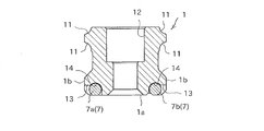
- FIG. 3 is a sectional view taken along line III-III in FIG. 2. It is a bottom view of the mounting plate of the track member according to the second embodiment.
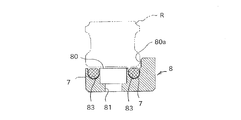
- FIG. 5 is a cross-sectional view taken along line VV in FIG. 4.
- FIG. 1 shows a first embodiment of a track member to which the present invention is applicable.
- the track member 1 is formed in a straight line, and a moving block 2 that is freely movable along the track member 1 is assembled via a large number of balls 3 as rolling elements.
- the track member 1 is laid on a fixed part such as a bed or a column, and various movable bodies are mounted on the moving block 2 so that the movable body can be reciprocally guided along the track member 1. Be able to.
- the track member 1 is formed in an elongated body having a substantially rectangular cross section.
- the track member 1 is formed with a plurality of bolt mounting holes 12 penetrating from the top surface to the bottom surface at predetermined intervals in the longitudinal direction.
- the track member 1 is attached to the track member 1 using fixing bolts inserted into the bolt mounting holes 12. It can be firmly fixed to fixing parts such as a bed and a column.
- the left and right side surfaces of the track member 1 are respectively provided with protrusions along the longitudinal direction, and one rolling surface 11 of the ball 3 is provided above and below these protrusions. Are provided with four rolling surfaces 11. Note that the number of rolling surfaces 11 provided on the raceway member 1 is not limited to this, and the rolling elements may be rollers instead of balls.
- the moving block 2 is roughly composed of a metal block main body 21 and a pair of synthetic resin end plates 22 attached to both ends of the block main body 21 in the moving direction.
- the moving block 2 includes a plurality of infinite circulation paths for the balls 3 corresponding to the rolling surfaces 11 of the raceway member, and the endless circulation paths fix the pair of end plates to both ends of the moving block 2. It is completed by.
- a flexible holding belt 30 is incorporated in each infinite circulation path, and a large number of balls 3 are arranged in a row on the holding belt 30. Accordingly, when the moving block is moved in the longitudinal direction of the track member 1 and the ball 3 rolls on the rolling surface of the track member 1, the holding belt 30 circulates together with the ball 3 in the endless circuit. To do.
- the shape and structure of the moving block 2 shown in FIG. 1 are merely examples in a rolling guide device to which the present invention can be applied, and are not limited to this, including the presence or absence of an infinite circulation path of rolling elements. . Further, only the balls 3 as rolling elements may be arranged in each infinite circulation path without using the holding belt 30.
- FIG. 1 is drawn with a quarter of the entire moving block 2 cut out so that the presence of the ball 3 and the holding belt 30 in the endless circulation path can be grasped.
- the track member 1 has a built-in heat pipe extending along the longitudinal direction of the track member 1. As shown in FIG. 1, the end of the heat pipe 7 protrudes from the end of the track member 1 in the longitudinal direction.
- a heat sink as a cooling device or a heater as a heating device is connected to the protruding end of the heat pipe 7, and the heat of the track member 1 is transferred to the outside via the heat pipe 7. It is possible to transfer heat to the track member 1 from the outside. Thereby, the temperature of the track member 1 is managed.
- FIG. 2 is a view showing a bottom surface of the track member 1 in contact with the fixed portion
- FIG. 3 is a cross-sectional view of the track member 1 cut along a plane orthogonal to the longitudinal direction.
- the track member may have a total length of several meters although the total length varies depending on the application.
- a plurality of heat pipes 7 are arranged at regular intervals along the longitudinal direction of the track member 1.
- the heat pipes 7 are not arranged in a row with respect to the track member 1 but are arranged in two rows so as to sandwich the bolt mounting holes 12 from both sides in the width direction of the track member 1.
- the heat pipes 7 in one row are not completely overlapped with the heat pipes 7 in the other row in the width direction of the track member, and have a positional shift in the longitudinal direction of the track member.
- FIG. 2 does not show the entire length of the track member 1, but shows only a predetermined length from one end in the longitudinal direction.
- the end of the heat pipe 7a protruding from one end of the track member overlaps with one end of the heat pipe 7b in the width direction of the track member.
- the other end of the heat pipe 7b overlaps with one end of another heat pipe 7c in the width direction of the track member.
- the end portions of the heat pipe 7a and the heat pipe 7b located on one side surface of the raceway member are not in contact with each other, and are arranged at a constant interval.
- the plurality of heat pipes 7 a, 7 b, 7 c are arranged in a staggered manner in two rows along the longitudinal direction of the track member 1, and this arrangement is repeated over the entire length of the track member 1.
- the heat pipes 7 are arranged in two rows with respect to the race member 1, but the heat pipes 7 are arranged in a staggered manner in three rows or more according to the size of the race member 1 and the like. There is no problem.
- each heat pipe 7 is bent toward the center in the width direction of the track member 1. That is, the end of the heat pipe 7 disposed on one side surface of the track member 1 is bent toward another heat pipe 7 disposed on the other side surface of the track member 1, and the bent heat The tip of the pipe 7 is arranged closer to the other heat pipe 7.
- each heat pipe 7 is fixed to a receiving groove 13 provided on the bottom surface of the track member 1.
- the receiving groove 13 is provided so as to cut out both corners on the bottom surface side of the track member 1, and is open to the bottom surface and the side surface of the track member 1.
- a concave groove along the outer shape of the heat pipe 7 formed in a circular cross section inside the housing groove 13 14 is formed. For this reason, when the heat pipe 7 is inserted into the housing groove 13 and the track member 1 is fixed to the fixed portion, the heat pipe 7 is sandwiched between the fixed portion and the concave groove 14, and the heat pipe 7 is fixed inside the receiving groove 13.
- a heat conductive material such as heat radiation grease is interposed between the two, The heat conductive material fills a minute gap between the housing groove 13 and the heat pipe 7. Thereby, the movement of the heat between the track member 1 and the heat pipe 7 can be performed smoothly.
- the track member 1 of the first embodiment for example, as a result of the moving block 2 repeatedly moving along the track member 1, only a part of the track member 1 in the longitudinal direction is caused by frictional heat with the ball 3. Even when the temperature rises, the heat is quickly transferred from the high-temperature part to the low-temperature part via the heat pipe 7.
- a plurality of heat pipes 7 are arranged in two rows with respect to the track member 1, and both ends of one heat pipe 7 in one row are two different in the other row in the width direction of the track member 1.
- the heat pipe 7 and the heat pipe 7 are arranged in an overlapping manner, the heat flowing into the heat pipe from the high-temperature portion of the track member is transferred from the heat pipe to the low-temperature portion of the track member, and further close to other heat. It is transferred to the cooler part of the track member through the pipe. For this reason, only a specific part of the track member does not become high temperature, and it becomes possible to quickly equalize the temperature over the entire region in the longitudinal direction of the track member.
- both ends of one heat pipe belonging to any one row are another row in the width direction of the track member. If the heat pipes 7 are arranged so as to overlap with two different heat pipes, the heat transfer using the heat pipe 7 is smoothly performed, and the temperature is quickly and uniformly distributed over the entire length of the track member. Can be realized.
- each heat pipe 7 is bent toward the center in the width direction of the track member 1, and the tip of the bent heat pipe 7 is the other heat pipe. 7, the heat transfer between the heat pipes 7 adjacent to each other in the width direction of the track member 1 can be performed smoothly. Therefore, also in this respect, the temperature can be quickly made uniform over the entire region of the track member 1 in the longitudinal direction.
- a cooling device such as a heat sink is connected to one end of the heat pipe 7a protruding from one end of the track member 1, the heat pipe 7a takes heat from the end of the track member 1. Therefore, coupled with the effect of the uniform temperature over the entire length of the track member 1 described above, the entire track member 1 can be cooled. Further, if a heating means such as a heater is connected to the end of the heat pipe 7a, the entire track member 1 can be similarly heated. Therefore, if the means for detecting the temperature of the track member 1 such as a temperature sensor is provided and the protruding end of the heat pipe 7a is cooled or heated based on the detection result, the entire track member 1 is controlled to an arbitrary temperature. It comes out.
- FIG. 4 shows a second embodiment of the track member of the rolling guide device of the present invention.
- the heat pipe is not directly built in the track member R so that the temperature control of the existing track member R can be easily performed, but between the track member R and the fixed portion.
- the mounting plate 8 of the track member R is provided in the mounting plate 8 and the heat pipe 7 is built in the mounting plate 8.
- FIG. 4 is a plan view of the mounting plate 8
- FIG. 5 is a cross-sectional view of the mounting plate 8 cut along a plane orthogonal to the longitudinal direction.
- the mounting plate 8 is a plate-like member interposed between the track member R and the fixed portion, and is formed to have substantially the same length as the track member R.
- An upper surface of the mounting plate 8 serves as a mounting surface 80 for the track member R, and an abutting surface 80a serving as a reference for fixing the track member is provided on one side of the mounting surface.
- the mounting plate 8 is fastened to the fixed portion by a fixing bolt, and a plurality of bolt mounting holes 81 therefor are formed through the mounting plate 8 at regular intervals in the longitudinal direction.
- a female screw hole 82 for fastening the track member R to the mounting plate 8 is provided between the bolt mounting holes 81 adjacent to each other.
- the heat pipes 7 are arranged in two rows with respect to the attachment surface 80 and are located on both sides of a plurality of bolt attachment holes 81 arranged in a row.
- One end of the heat pipe located at the longitudinal end of the mounting plate protrudes from the mounting plate.
- a heat sink as a cooling device or a heater as a heating device is connected to the protruding end.
- the heat of the mounting plate 8 can be transferred to the outside via the heat pipe 7 or the heat can be transferred to the mounting plate 8 from the outside.
- the mounting surface 80 is provided with two housing grooves 83a and 83b for fixing the heat pipe 7, and these housing grooves 83a and 83b are continuous from one end to the other end of the mounting plate 8.
- a plurality of heat pipes 7 are continuously arranged in the housing grooves 83a and 83b without any gaps. That is, one end of the heat pipe 7 disposed in the housing grooves 83 a and 83 b is close enough to come into contact with one end of the other heat pipe 7. Further, the joint of the heat pipe 7 in one housing groove 83a is displaced with respect to the longitudinal direction of the track member R with respect to the joint of the heat pipe 7 in the other housing groove 83b.
- the plurality of heat pipes 7 are arranged in two rows along the longitudinal direction of the track member R, and both ends of one heat pipe 7 in one row are connected to the track member R.
- the heat pipes 7 are arranged so as to overlap the two heat pipes 7 in the other row in the width direction, and this arrangement is repeated over the entire length of the track member R.
- the heat pipes 7 are arranged in two rows with respect to the mounting plate 8.
- the heat pipes 7 are arranged in three or more rows in a staggered manner according to the size of the mounting plate 8. There is no problem.
- the circular cross section of the housing groove 83 is formed in an arc shape along the outer shape of the heat pipe 7. For this reason, when the heat pipe 7 is arranged in the housing groove 83 and the race member R is fixed to the mounting plate 8, the heat pipe 7 is sandwiched between the race member and the housing groove 83, and the heat The pipe 7 is fixed inside the accommodation groove 83.
- a heat conductive material such as heat radiation grease (not shown) is provided between them.
- the thermal conductive material fills a minute gap between the housing groove 83 and the heat pipe 7.
- the mounting plate 8 When the track member R is laid on the fixed portion using the mounting plate 8, first, the mounting plate 8 is fastened to the fixed portion using a fixing bolt, and then a track having a thermally conductive material applied to the bottom surface. The member R is fastened to the mounting plate 8 with fixing bolts. Thereby, heat transfer between the track member and the mounting plate is favorably performed.
- a plurality of heat pipes 7 are arranged in the mounting plate 8 in two rows along the longitudinal direction of the track member R, as in the track member 1 of the first embodiment, and one heat pipe in one row. 7 is arranged so as to overlap two heat pipes 7 in the other row with respect to the width direction of the track member R, so that only a part of the track member R in the longitudinal direction is heated. Even so, the heat of the track member R is transferred to the mounting plate 8 and further quickly transferred in the longitudinal direction in the mounting plate 8 via the heat pipe 7. Thereby, only a specific part of the track member 1 does not become high temperature, and it becomes possible to quickly equalize the temperature over the entire region in the longitudinal direction of the track member 1. Further, if a cooling device or a heating device is connected to one end of the heat pipe 7 protruding from one end of the mounting plate 8, the entire track member R can be controlled to an arbitrary temperature.
- both ends of one heat pipe belonging to any one row are different in the width direction of the mounting plate 8. If the heat pipes 7 are arranged so as to overlap with two different heat pipes belonging to one row, the heat transfer using the heat pipes 7 is performed smoothly, and the temperature is rapidly increased over the entire longitudinal direction of the mounting plate 8. It becomes possible to make uniform.
- the mounting plate 8 according to the second embodiment it is possible to easily manage the temperature of a conventional track rail that does not incorporate the heat pipe 7.
Landscapes
- Engineering & Computer Science (AREA)
- General Engineering & Computer Science (AREA)
- Mechanical Engineering (AREA)
- Life Sciences & Earth Sciences (AREA)
- Sustainable Development (AREA)
- Physics & Mathematics (AREA)
- Thermal Sciences (AREA)
- Bearings For Parts Moving Linearly (AREA)
Abstract
ヒートパイプ(7)を用いて効率的に冷却又は加熱の温度制御を行うことができ、数mに及ぶ長尺なものであっても当該温度制御を確実に行うことが可能な転がり案内装置の軌道部材(1)を提供する。複数のヒートパイプ(7)を内蔵し、これらヒートパイプ(7)は当該軌道部材(1)の長手方向に沿って少なくとも二列で配列されると共に、いずれかの一列に属する1本のヒートパイプ(7)の両端は当該軌道部材(1)の幅方向に関して他の一列に属する異なる2本のヒートパイプ(7)と重複して配列されており、当該軌道部材(1)の長手方向の端部に位置するヒートパイプ(7)は一端が当該軌道部材(1)から突出すると共に、当該突出端には冷却装置又は加熱装置が接続されるように構成されている。
Description
本発明は、工作機械や各種産業用ロボットの直線案内部や曲線案内部に使用される転がり案内装置において、移動ブロックを直線状又は円弧状に案内する軌道部材に関するものである。
従来、工作機械や各種産業ロボットの案内部を構成する転がり案内装置としては、長手方向に沿ってボール転走面が形成された直線状又は円弧状の軌道部材と、この軌道部材に対して多数のボールを介して組付けられた移動ブロックとから構成されるものが知られている。前記移動ブロックは軌道部材のボール転走面に対向する負荷転走面を具備すると共に、この負荷転走面と軌道部材の転走面との間で荷重を負荷しながら転走する多数のボールを無限循環させる循環路を具備しており、ボールを無限循環路内で循環させることにより、移動ブロックが軌道部材の全長にわたって自在に移動することが可能となっている。
通常、前記軌道部材は工作機械等のベッドやコラムといった固定部に対して固定ボルトを締結することで固定されている。一般的に、前記軌道部材は前記転走面に焼き入れ処理を施すために炭素鋼から形成されているが、前記固定部の材質は転がり案内装置の用途に応じて様々であり、両者の熱膨張係数は相違する。近年では前記固定部として繊維強化プラスチックが用いられる場合があり、当該固定部の熱膨張係数が前記軌道部材に比べて著しく小さいこともある。このため、前記固定部に対して軌道部材を締結した後に温度変化が生じると、熱膨張係数の差によっては、前記軌道部材の伸縮量と前記固定部の伸縮量に大きな相違が生じ、当該軌道部材の変形が誘因され、前記移動ブロックの走行精度が損なわれる懸念がある。
特許文献1には、前記軌道部材の温度変化を積極的に制御して当該軌道部材の変形の防止を図る転がり案内装置が開示されている。この転がり案内装置では、前記軌道部材の長手方向の全長にわたって熱媒体の流路が設けられると共に、当該流路には熱媒体を循環させるためのチラーが接続されている。
一般的に、物体の冷却や加熱といった熱の移動を効率的に行う仕組みとしてヒートパイプが知られており、前記軌道部材の温度制御をより効率的に行うことを考慮すると、前記熱媒体の流路に代えてヒートパイプを使用することが考えられる。
しかし、ヒートパイプはその内部構造の関係上、製作できる長さに制限があり、数mに及ぶ長尺な軌道部材の全長にわたって1本のヒートパイプを設けることは困難である。
本発明はこのような問題点に鑑みなされたものであり、その目的とするところは、ヒートパイプを用いて効率的に冷却又は加熱の温度制御を行うことができ、数mに及ぶ長尺なものであっても当該温度制御を確実に行うことが可能な転がり案内装置の軌道部材を提供することにある。
すなわち、本発明は、転がり案内装置の軌道部材であって、複数のヒートパイプを内蔵し、これらヒートパイプは当該軌道部材の長手方向に沿って少なくとも二列で配列されると共に、いずれかの一列に属する1本のヒートパイプの両端は当該軌道部材の幅方向に関して他の一列に属する異なる2本のヒートパイプと重複して配列されており、当該軌道部材の長手方向の端部に位置するヒートパイプは一端が当該軌道部材から突出すると共に、当該突出端には冷却装置又は加熱装置が接続されるように構成されている。
本発明によれば、軌道部材には当該軌道部材の長手方向に沿ってヒートパイプが少なくとも二列で配列されると共に、いずれかの一列に属する1本のヒートパイプの両端は当該軌道部材の幅方向に関して他の一列に属する異なる2本のヒートパイプと重複して配列されていることから、いずれかの一列に属するヒートパイプから他の一列に属するヒートパイプへの伝熱が容易に行われ、長さの短い複数のヒートパイプを組み合わせて使用しつつも、軌道部材の全体の温度が均一化し易くなる。加えて、当該軌道部材の長手方向の端部から突出したヒートパイプに対して冷却装置又は加熱装置を接続することにより、当該軌道部材の温度を任意に制御することが可能となる。
以下、添付図面を用いて本発明の転がり案内装置の軌道部材を詳細に説明する。
図1は本発明を適用可能な軌道部材の第一実施形態を示すものである。この軌道部材1は直線状に形成されると共に、当該軌道部材1に沿って自在に移動可能な移動ブロック2が転動体としての多数のボール3を介して組付けられている。ベッド、コラム等の固定部に前記軌道部材1を敷設すると共に、前記移動ブロック2に対して各種の可動体を搭載することで、かかる可動体を軌道部材1に沿って往復移動自在に案内することができるようになっている。
前記軌道部材1は略断面四角形状の長尺体に形成されている。この軌道部材1には長手方向に所定の間隔をおいて上面から底面に貫通するボルト取付け孔12が複数形成されており、これらボルト取付け孔12に挿入した固定ボルトを用いて、軌道部材1をベッド、コラム等の固定部に対して強固に固定することができるようになっている。前記軌道部材1の左右両側面には長手方向に沿って突部がそれぞれ設けられると共に、これら突部の上下にはボール3の転走面11が1条ずつ設けられ、軌道部材1の全体としては4条の転走面11が設けられている。尚、前記軌道部材1に設けられる転走面11の条数はこれに限られるものではなく、また、前記転動体はボールではなくローラであってもよい。
一方、前記移動ブロック2は、大きく分けて、金属製のブロック本体21と、このブロック本体21の移動方向の両端に装着される一対の合成樹脂製のエンドプレート22とから構成されている。この移動ブロック2は前記軌道部材の各転走面11に対応してボール3の無限循環路を複数備えており、かかる無限循環路は前記移動ブロック2の両端に前記一対のエンドプレートを固定することによって完成している。各無限循環路には可撓性の保持ベルト30が組み込まれており、かかる保持ベルト30には多数のボール3が一列に配列されている。従って、前記移動ブロックが2前記軌道部材1の長手方向へ動かされ、前記ボール3が前記軌道部材1の転走面を転がると、前記保持ベルト30がボール3と一緒に前記無限循環路を循環する。
尚、図1に示した移動ブロック2の形状及び構造は、あくまでも本発明を適用可能な転がり案内装置における例示であり、転動体の無限循環路の有無も含め、これに限定されるものではない。また、各無限循環路には前記保持ベルト30を用いることなく、転動体としてのボール3のみを配列しても差し支えない。
また、前記移動ブロックには当該移動ブロックと軌道部材との隙間を密閉する各種シール部材4,5,6が固定されており、軌道部材1に付着した塵芥などが前記無限循環路の内部に侵入するのを防止している。尚、図1は前記無限循環路内におけるボール3及び保持ベルト30の存在を把握できるように、前記移動ブロック2の全体の1/4を切り欠いて描いてある。
前記軌道部材1には当該軌道部材1の長手方向に沿って延びるヒートパイプが内蔵されている。図1に示すように、前記軌道部材1の長手方向の端部からはヒートパイプ7の端部が突出している。図示はしていないが、このヒートパイプ7の突出端には、例えば、冷却装置としてのヒートシンクや加熱装置としてのヒータが接続され、前記ヒートパイプ7を介して前記軌道部材1の熱を外部に移送し、あるいは外部から前記軌道部材1に対して熱を移送することが可能である。これによって前記軌道部材1の温度を管理している。
図2は固定部と接する前記軌道部材1の底面を示す図であり、また、図3は前記軌道部材1を長手方向と直交する面で切断した断面図である。一般的にヒートパイプは構造上の理由から全長数mのものを製造するのが難しく、仮に製造できたとしても製造コストが嵩んでしまう。これに対し、前記軌道部材は用途によってその全長は異なるが、全長数mに及ぶ場合もある。
このため、本発明では前記軌道部材1の長手方向に沿って複数のヒートパイプ7を一定の間隔で配列している。また、前記ヒートパイプ7は前記軌道部材1に対して一列で配列するのではなく、当該軌道部材1の幅方向の両側から前記ボルト取付け孔12を挟むようにして二列で配列している。一方の列のヒートパイプ7は前記軌道部材の幅方向に関して他方の列のヒートパイプ7と完全には重複しておらず、当該軌道部材の長手方向に関して位置ずれを有している。
図2は前記軌道部材1の全長を示しておらず、長手方向の一端から所定の長さのみを示している。同図において、前記軌道部材の一端から突出しているヒートパイプ7aの端部は、当該軌道部材の幅方向に関してヒートパイプ7bの一方の端部と重複している。また、ヒートパイプ7bの他方の端部は当該軌道部材の幅方向に関して別のヒートパイプ7cの一方の端部と重複している。また、前記軌道部材の一方の側面に位置する前記ヒートパイプ7aとヒートパイプ7bとは、その端部同士は接触しておらず、一定の間隔をおいて配列されている。すなわち、複数のヒートパイプ7a,7b,7cは軌道部材1の長手方向に沿って二列に千鳥配列されており、この配列が当該軌道部材1の全長にわたって繰り返されている。尚、この第一実施形態では前記軌道部材1に対してヒートパイプ7を二列で配列したが、当該軌道部材1の大きさ等に応じて、ヒートパイプ7を三列以上で千鳥配列しても差し支えない。
また、図2に示す実施形態において、各ヒートパイプ7の端部は前記軌道部材1の幅方向の中央に向けて屈曲している。すなわち、前記軌道部材1の一方の側面に配置されたヒートパイプ7の端部は、当該軌道部材1の他方の側面に配置された別のヒートパイプ7に向けて屈曲しており、屈曲したヒートパイプ7の先端が他のヒートパイプ7に一層接近した配置となっている。
図3に示すように、各ヒートパイプ7は前記軌道部材1の底面に設けられた収容溝13に固定されている。前記収容溝13は前記軌道部材1の底面側の両角部を切り欠くようにして設けられており、当該軌道部材1の底面と側面に開放されている。また、前記収容溝13と前記ヒートパイプ7との間の伝熱を良好なものにするため、当該収容溝13の内部には断面円形状に形成された前記ヒートパイプ7の外形に沿う凹溝14が形成されている。このため、前記収容溝13に対してヒートパイプ7を挿入し、前記軌道部材1を固定部に固定すると、当該固定部と前記凹溝14との間にヒートパイプ7が挟まれ、かかるヒートパイプ7が収容溝13の内部に固定される。
更に、前記収容溝13と前記ヒートパイプ7との間の伝熱を良好なものにするため、これら両者の間には放熱グリース等の熱伝導性物質(図示せず)が介在しており、当該熱伝導性物質が前記収容溝13と前記ヒートパイプ7との間の微小隙間を埋めている。これにより、前記軌道部材1と前記ヒートパイプ7との間における熱の移動を円滑に行うことができる。
この第一実施形態の軌道部材1では、例えば前記移動ブロック2が当該軌道部材1に沿って繰り返し移動した結果として、ボール3との摩擦熱で当該軌道部材1の長手方向の一部の部位のみが昇温した場合であっても、前記ヒートパイプ7を介して高温の部位から低温の部位へ熱が速やかに移送される。しかも複数のヒートパイプ7が軌道部材1に対して二列で配列されると共に、一方の列の1本のヒートパイプ7の両端は当該軌道部材1の幅方向に関して他方の列の異なる2本のヒートパイプ7と重複して配列されているので、当該軌道部材の高温部位からヒートパイプへ流入した熱は、このヒートパイプから当該軌道部材の低温の部位へと移送され、更に近接する他のヒートパイプを伝わって当該軌道部材の一層低温の部位へと移送される。このため、前記軌道部材の特定の部位のみが高温になることはなく、当該軌道部材の長手方向の全域にわたって温度を迅速に均一化することが可能となる。
また、前記軌道部材1に対して前記ヒートパイプ7を3列以上で配列した場合であっても、いずれかの一列に属する1本のヒートパイプの両端が当該軌道部材の幅方向に関して他の一列に属する異なる2本のヒートパイプと重複して配列されているのであれば、当該ヒートパイプ7を用いた熱の移送は円滑に行われ、当該軌道部材の長手方向の全域にわたって温度を迅速に均一化することが可能となる。
特に、図2に示した第一実施形態では、各ヒートパイプ7の端部が前記軌道部材1の幅方向の中央に向けて屈曲しており、屈曲したヒートパイプ7の先端が他のヒートパイプ7に接近した配置となっているので、当該軌道部材1の幅方向に隣接するヒートパイプ7同士の間での伝熱を円滑に行うことが可能である。従って、この点においても当該軌道部材1の長手方向の全域にわたって温度を迅速に均一化することができる。
そして、前記軌道部材1の一端から突出しているヒートパイプ7aの一端に対して、例えばヒートシンク等の冷却装置を接続すれば、当該ヒートパイプ7aが軌道部材1の端部から熱を奪い取ることになるので、前述した当該軌道部材1の長手方向の全域にわたる温度の均一化の効果と相まって、当該軌道部材1の全体を冷却することが可能となる。また、前記ヒートパイプ7a端部にヒータなどの加熱手段を接続すれば、同様にして、当該軌道部材1の全体を加熱することが可能となる。従って、温度センサー等の軌道部材1の温度を検知する手段を設け、その検知結果に基づいてヒートパイプ7aの突出端を冷却又は加熱すれば、前記軌道部材1の全体を任意の温度に制御することがでる。
図4は本発明の転がり案内装置の軌道部材の第二実施形態を示すものである。
この第二実施形態は、既存の軌道部材Rの温度管理を容易に行うことができるよう、軌道部材Rに対してヒートパイプを直接に内蔵するのではなく、軌道部材Rと固定部との間に当該軌道部材Rの取付けプレート8を設け、前記ヒートパイプ7をこの取付けプレート8に内蔵している。
図4は前記取付けプレート8の平面図であり、また、図5は前記取付けプレート8を長手方向と直交する面で切断した断面図である。前記取付けプレート8は前記軌道部材Rと前記固定部との間に介在する板状部材であり、当該軌道部材Rと略同じ長さに形成されている。この取付けプレート8の上面は前記軌道部材Rの取付け面80となっており、当該取付け面の一側には前記軌道部材の固定基準となる突き当て面80aが設けられている。また、この取付けプレート8は固定ボルトによって前記固定部に締結され、当該取付けプレート8にはそのための複数のボルト取付け孔81が長手方向に一定の間隔をおいて貫通形成されている。互いに隣接するボルト取付け孔81の間には前記軌道部材Rを当該取付けプレート8に締結するための雌ねじ穴82が設けられている。
前記ヒートパイプ7は記取付け面80に対して二列で配列され、一列に配列された複数のボルト取付け孔81の両側に位置している。取付けプレートの長手方向の端部に位置するヒートパイプは、その一端が当該取付けプレートから突出しており、かかる突出端に対しては、例えば、冷却装置としてのヒートシンクや加熱装置としてのヒータが接続され、前記ヒートパイプ7を介して前記取付けプレート8の熱を外部に移送し、あるいは外部から前記取付けプレート8に対して熱を移送することが可能である。
前記取付け面80には前記ヒートパイプ7を固定するための2本の収容溝83a,83bが設けられており、これら収容溝83a,83bは取付けプレート8の一端から他端まで連続している。各収容溝83a,83bの中には複数のヒートパイプ7が間隔を空けることなく連続的に並べられている。すなわち、収容溝83a,83b内に配置されたヒートパイプ7の一端は他のヒートパイプ7の一端と接する程度に近接している。また、一方の収容溝83a内のヒートパイプ7の継ぎ目は、他方の収容溝83b内のヒートパイプ7の継ぎ目に対して、前記軌道部材Rの長手方向に関して位置ずれを有している。すなわち、この第二実施形態においても複数のヒートパイプ7は軌道部材Rの長手方向に沿って二列で配列されており、一方の列の1本のヒートパイプ7の両端は当該軌道部材Rの幅方向に関して他方の列の異なる2本のヒートパイプ7と重複して配列されており、この配列が当該軌道部材Rの全長にわたって繰り返されている。尚、この第二実施形態では前記取付けプレート8に対してヒートパイプ7を二列で配列したが、当該取付けプレート8の大きさ等に応じて、ヒートパイプ7を三列以上で千鳥配列しても差し支えない。
また、前記収容溝13と前記ヒートパイプ7との間の伝熱を良好なものにするため、前記収容溝83の断面円形状は前記ヒートパイプ7の外形に沿う円弧状に形成されている。このため、前記収容溝83に対してヒートパイプ7を配置し、前記軌道部材Rを取付けプレート8に固定すると、当該軌道部材と前記収容溝83との間にヒートパイプ7が挟まれ、かかるヒートパイプ7が収容溝83の内部に固定される。
更に、この実施形態においても、前記収容溝83と前記ヒートパイプ7との間の伝熱を良好なものにするため、これら両者の間には放熱グリース等の熱伝導性物質(図示せず)が介在しており、当該熱伝導性物質が前記収容溝83と前記ヒートパイプ7との間の微小隙間を埋めている。
この取付けプレート8を用いて軌道部材Rを固定部に敷設する際には、先ずは固定ボルトを用いて前記取付けプレート8を固定部に締結し、次いで、底面に熱伝導性物質を塗布した軌道部材Rを前記取付けプレート8に固定ボルトで締結する。これにより、前記軌道部材と取付けプレートの間における伝熱が良好に行われる。
前記取付けプレート8には第一実施形態の軌道部材1と同様に複数のヒートパイプ7が前記軌道部材Rの長手方向に沿って二列で配列されると共に、一方の列の1本のヒートパイプ7の両端は当該軌道部材Rの幅方向に関して他方の列の異なる2本のヒートパイプ7と重複して配列されているので、軌道部材Rの長手方向の一部の部位のみが昇温した場合であっても、当該軌道部材Rの熱は前記取付けプレート8に伝熱され、更に前記ヒートパイプ7を介して前記取付けプレート8内を長手方向に速やかに移送される。これにより、前記軌道部材1の特定の部位のみが高温になることはなく、当該軌道部材1の長手方向の全域にわたって温度を迅速に均一化することが可能となる。また、前記取付けプレート8の一端から突出しているヒートパイプ7の一端に冷却装置又は加熱装置を接続すれば、前記軌道部材Rの全体を任意の温度に制御することがでる。
また、前記取付けプレート8に対して前記ヒートパイプ7を3列以上で配列した場合であっても、いずれかの一列に属する1本のヒートパイプの両端が当該取付けプレート8の幅方向に関して他の一列に属する異なる2本のヒートパイプと重複して配列されているのであれば、当該ヒートパイプ7を用いた熱の移送は円滑に行われ、当該取付けプレート8の長手方向の全域にわたって温度を迅速に均一化することが可能となる。
従って、この第二実施形態に係る取付けプレート8を用いれば、ヒートパイプ7を内蔵しない従来の軌道レールであっても容易にその温度管理を行うことが可能となる。
Claims (6)
- 転がり案内装置の軌道部材(1)であって、
複数のヒートパイプ(7)を内蔵し、これらヒートパイプ(7)は当該軌道部材(1)の長手方向に沿って少なくとも二列で配列されると共に、いずれかの一列に属する1本のヒートパイプ(79の両端は当該軌道部材の幅方向に関して他の一列に属する異なる2本のヒートパイプと重複して配列されており、
当該軌道部材(1)の長手方向の端部に位置するヒートパイプ(7)は一端が当該軌道部材(1)から突出すると共に、当該突出端には冷却装置又は加熱装置が接続されることを特徴とする軌道部材。 - 前記ヒートパイプ(7)を固定する収容溝(13)が設けられ、当該ヒートパイプ(7)と前記収容溝(13)の間には熱伝導性物質が介在していることを特徴する請求項1記載の軌道部材。
- 各ヒートパイプ(7)の端部は前記軌道部材(1)の幅方向の中央に向けて屈曲していることを特徴とする請求項1記載の軌道部材。
- 転がり案内装置の軌道部材(1)を固定部に敷設する際に、当該軌道部材と固定部との間に固定される取付けプレート(8)であって、
複数のヒートパイプ(7)を内蔵し、これらヒートパイプ(7)は当該軌道部材(1)の長手方向に沿って少なくとも二列で配列されると共に、いずれかの一列に属する1本のヒートパイプ(7)の両端は当該軌道部材(1)の幅方向に関して他の一列に属する異なる2本のヒートパイプ(7)と重複して配列されており、
当該取付けプレート(8)の長手方向の端部に位置するヒートパイプ(7)は一端が当該取付けプレート(8)から突出すると共に、当該突出端には冷却装置又は加熱装置が接続されることを特徴とする取付けプレート。 - 前記ヒートパイプ(7)を固定する収容溝(13)が設けられ、当該ヒートパイプ(7)と前記収容溝(13)の間には熱電導性物質が介在していることを特徴する請求項4記載の取付けプレート。
- 各ヒートパイプ(7)の端部は前記取付けプレート(8)の幅方向の中央に向けて屈曲していることを特徴とする請求項4記載の取付けプレート。
Priority Applications (1)
| Application Number | Priority Date | Filing Date | Title |
|---|---|---|---|
| DE112017002297.5T DE112017002297B4 (de) | 2016-05-02 | 2017-04-11 | Spurelement einer Rollführungsvorrichtung |
Applications Claiming Priority (2)
| Application Number | Priority Date | Filing Date | Title |
|---|---|---|---|
| JP2016092240A JP6218883B1 (ja) | 2016-05-02 | 2016-05-02 | 転がり案内装置の軌道部材 |
| JP2016-092240 | 2016-05-02 |
Publications (1)
| Publication Number | Publication Date |
|---|---|
| WO2017191736A1 true WO2017191736A1 (ja) | 2017-11-09 |
Family
ID=60156760
Family Applications (1)
| Application Number | Title | Priority Date | Filing Date |
|---|---|---|---|
| PCT/JP2017/014785 Ceased WO2017191736A1 (ja) | 2016-05-02 | 2017-04-11 | 転がり案内装置の軌道部材 |
Country Status (4)
| Country | Link |
|---|---|
| JP (1) | JP6218883B1 (ja) |
| DE (1) | DE112017002297B4 (ja) |
| TW (1) | TWI713730B (ja) |
| WO (1) | WO2017191736A1 (ja) |
Cited By (2)
| Publication number | Priority date | Publication date | Assignee | Title |
|---|---|---|---|---|
| US10520018B2 (en) | 2017-09-15 | 2019-12-31 | Robert Bosch Gmbh | Guiding rail, substructure for securing a guiding rail and arrangement having a guiding rail and a substructure |
| US10962052B2 (en) * | 2016-05-24 | 2021-03-30 | Robert Bosch Gmbh | Guide rail with fastening holes and heat sink |
Citations (3)
| Publication number | Priority date | Publication date | Assignee | Title |
|---|---|---|---|---|
| JP2004092764A (ja) * | 2002-08-30 | 2004-03-25 | Dainippon Printing Co Ltd | ロール軸移動機構 |
| WO2005077597A1 (ja) * | 2004-02-18 | 2005-08-25 | Horkos Corporation | 工作機械の直動案内装置 |
| JP2015175422A (ja) * | 2014-03-14 | 2015-10-05 | 日本精工株式会社 | 案内レール、転がり軸受案内装置 |
Family Cites Families (1)
| Publication number | Priority date | Publication date | Assignee | Title |
|---|---|---|---|---|
| JP2632445B2 (ja) | 1991-03-15 | 1997-07-23 | テイエチケー株式会社 | 直動軸受用中空軌道台 |
-
2016
- 2016-05-02 JP JP2016092240A patent/JP6218883B1/ja active Active
-
2017
- 2017-04-11 DE DE112017002297.5T patent/DE112017002297B4/de active Active
- 2017-04-11 WO PCT/JP2017/014785 patent/WO2017191736A1/ja not_active Ceased
- 2017-04-20 TW TW106113311A patent/TWI713730B/zh active
Patent Citations (3)
| Publication number | Priority date | Publication date | Assignee | Title |
|---|---|---|---|---|
| JP2004092764A (ja) * | 2002-08-30 | 2004-03-25 | Dainippon Printing Co Ltd | ロール軸移動機構 |
| WO2005077597A1 (ja) * | 2004-02-18 | 2005-08-25 | Horkos Corporation | 工作機械の直動案内装置 |
| JP2015175422A (ja) * | 2014-03-14 | 2015-10-05 | 日本精工株式会社 | 案内レール、転がり軸受案内装置 |
Cited By (2)
| Publication number | Priority date | Publication date | Assignee | Title |
|---|---|---|---|---|
| US10962052B2 (en) * | 2016-05-24 | 2021-03-30 | Robert Bosch Gmbh | Guide rail with fastening holes and heat sink |
| US10520018B2 (en) | 2017-09-15 | 2019-12-31 | Robert Bosch Gmbh | Guiding rail, substructure for securing a guiding rail and arrangement having a guiding rail and a substructure |
Also Published As
| Publication number | Publication date |
|---|---|
| JP2017201178A (ja) | 2017-11-09 |
| DE112017002297T5 (de) | 2019-02-28 |
| TW201807326A (zh) | 2018-03-01 |
| DE112017002297B4 (de) | 2025-08-07 |
| JP6218883B1 (ja) | 2017-10-25 |
| TWI713730B (zh) | 2020-12-21 |
Similar Documents
| Publication | Publication Date | Title |
|---|---|---|
| US20120200178A1 (en) | Linear motor actuator | |
| JP6218883B1 (ja) | 転がり案内装置の軌道部材 | |
| JP6173217B2 (ja) | 運動案内装置 | |
| US20150337899A1 (en) | Motion-guiding device | |
| US7066650B2 (en) | Linear motion guide unit | |
| JP2015175422A (ja) | 案内レール、転がり軸受案内装置 | |
| CN104729143A (zh) | 具有热电元件的热交换器 | |
| JP5695248B2 (ja) | 運動案内装置 | |
| JP4071212B2 (ja) | 転がり素子案内モジュール | |
| JP6436949B2 (ja) | 直動装置 | |
| KR102157714B1 (ko) | 이송 시스템, 특히, 연신 유닛용 측면 가이드 레일 | |
| US9249828B2 (en) | Rolling guidance device | |
| KR101560127B1 (ko) | 운동 안내 장치 | |
| JP2009535002A (ja) | 熱補償手段並びに冷却手段を有するリニア電気モータ用のスタンド | |
| CN110678662A (zh) | 多列滚动体收容带及运动引导装置 | |
| JP2018078668A (ja) | リニアモータ | |
| JP2006105296A (ja) | ローラ式リニアガイドウェイ | |
| JP6364157B2 (ja) | 運動案内装置 | |
| JP2011085247A (ja) | 運動案内装置 | |
| JP2017211015A (ja) | 転がり案内装置 | |
| JP5494850B2 (ja) | 直動装置 | |
| US9273722B2 (en) | Rolling guide device | |
| JP7333939B2 (ja) | 放射パネルの連結構造 | |
| JP2012087904A (ja) | ボール連結ベルト及びこれを用いた運動案内装置 | |
| WO2013168359A1 (ja) | 運動案内装置 |
Legal Events
| Date | Code | Title | Description |
|---|---|---|---|
| 121 | Ep: the epo has been informed by wipo that ep was designated in this application |
Ref document number: 17792669 Country of ref document: EP Kind code of ref document: A1 |
|
| 122 | Ep: pct application non-entry in european phase |
Ref document number: 17792669 Country of ref document: EP Kind code of ref document: A1 |
|
| WWG | Wipo information: grant in national office |
Ref document number: 112017002297 Country of ref document: DE |