WO2017188460A1 - Système de commande, machine de travail et procédé de commande - Google Patents
Système de commande, machine de travail et procédé de commande Download PDFInfo
- Publication number
- WO2017188460A1 WO2017188460A1 PCT/JP2017/027340 JP2017027340W WO2017188460A1 WO 2017188460 A1 WO2017188460 A1 WO 2017188460A1 JP 2017027340 W JP2017027340 W JP 2017027340W WO 2017188460 A1 WO2017188460 A1 WO 2017188460A1
- Authority
- WO
- WIPO (PCT)
- Prior art keywords
- hydraulic
- engine
- hydraulic pump
- state
- flow rate
- Prior art date
Links
Images


Classifications
-
- E—FIXED CONSTRUCTIONS
- E02—HYDRAULIC ENGINEERING; FOUNDATIONS; SOIL SHIFTING
- E02F—DREDGING; SOIL-SHIFTING
- E02F9/00—Component parts of dredgers or soil-shifting machines, not restricted to one of the kinds covered by groups E02F3/00 - E02F7/00
- E02F9/20—Drives; Control devices
- E02F9/22—Hydraulic or pneumatic drives
- E02F9/2203—Arrangements for controlling the attitude of actuators, e.g. speed, floating function
-
- E—FIXED CONSTRUCTIONS
- E02—HYDRAULIC ENGINEERING; FOUNDATIONS; SOIL SHIFTING
- E02F—DREDGING; SOIL-SHIFTING
- E02F3/00—Dredgers; Soil-shifting machines
- E02F3/04—Dredgers; Soil-shifting machines mechanically-driven
- E02F3/28—Dredgers; Soil-shifting machines mechanically-driven with digging tools mounted on a dipper- or bucket-arm, i.e. there is either one arm or a pair of arms, e.g. dippers, buckets
- E02F3/30—Dredgers; Soil-shifting machines mechanically-driven with digging tools mounted on a dipper- or bucket-arm, i.e. there is either one arm or a pair of arms, e.g. dippers, buckets with a dipper-arm pivoted on a cantilever beam, i.e. boom
-
- E—FIXED CONSTRUCTIONS
- E02—HYDRAULIC ENGINEERING; FOUNDATIONS; SOIL SHIFTING
- E02F—DREDGING; SOIL-SHIFTING
- E02F3/00—Dredgers; Soil-shifting machines
- E02F3/04—Dredgers; Soil-shifting machines mechanically-driven
- E02F3/28—Dredgers; Soil-shifting machines mechanically-driven with digging tools mounted on a dipper- or bucket-arm, i.e. there is either one arm or a pair of arms, e.g. dippers, buckets
- E02F3/36—Component parts
- E02F3/42—Drives for dippers, buckets, dipper-arms or bucket-arms
- E02F3/43—Control of dipper or bucket position; Control of sequence of drive operations
- E02F3/431—Control of dipper or bucket position; Control of sequence of drive operations for bucket-arms, front-end loaders, dumpers or the like
-
- E—FIXED CONSTRUCTIONS
- E02—HYDRAULIC ENGINEERING; FOUNDATIONS; SOIL SHIFTING
- E02F—DREDGING; SOIL-SHIFTING
- E02F9/00—Component parts of dredgers or soil-shifting machines, not restricted to one of the kinds covered by groups E02F3/00 - E02F7/00
- E02F9/20—Drives; Control devices
- E02F9/2058—Electric or electro-mechanical or mechanical control devices of vehicle sub-units
- E02F9/2062—Control of propulsion units
- E02F9/2066—Control of propulsion units of the type combustion engines
-
- E—FIXED CONSTRUCTIONS
- E02—HYDRAULIC ENGINEERING; FOUNDATIONS; SOIL SHIFTING
- E02F—DREDGING; SOIL-SHIFTING
- E02F9/00—Component parts of dredgers or soil-shifting machines, not restricted to one of the kinds covered by groups E02F3/00 - E02F7/00
- E02F9/20—Drives; Control devices
- E02F9/22—Hydraulic or pneumatic drives
- E02F9/2221—Control of flow rate; Load sensing arrangements
- E02F9/2239—Control of flow rate; Load sensing arrangements using two or more pumps with cross-assistance
- E02F9/2242—Control of flow rate; Load sensing arrangements using two or more pumps with cross-assistance including an electronic controller
-
- E—FIXED CONSTRUCTIONS
- E02—HYDRAULIC ENGINEERING; FOUNDATIONS; SOIL SHIFTING
- E02F—DREDGING; SOIL-SHIFTING
- E02F9/00—Component parts of dredgers or soil-shifting machines, not restricted to one of the kinds covered by groups E02F3/00 - E02F7/00
- E02F9/20—Drives; Control devices
- E02F9/22—Hydraulic or pneumatic drives
- E02F9/2246—Control of prime movers, e.g. depending on the hydraulic load of work tools
-
- E—FIXED CONSTRUCTIONS
- E02—HYDRAULIC ENGINEERING; FOUNDATIONS; SOIL SHIFTING
- E02F—DREDGING; SOIL-SHIFTING
- E02F9/00—Component parts of dredgers or soil-shifting machines, not restricted to one of the kinds covered by groups E02F3/00 - E02F7/00
- E02F9/20—Drives; Control devices
- E02F9/22—Hydraulic or pneumatic drives
- E02F9/2264—Arrangements or adaptations of elements for hydraulic drives
- E02F9/2271—Actuators and supports therefor and protection therefor
-
- E—FIXED CONSTRUCTIONS
- E02—HYDRAULIC ENGINEERING; FOUNDATIONS; SOIL SHIFTING
- E02F—DREDGING; SOIL-SHIFTING
- E02F9/00—Component parts of dredgers or soil-shifting machines, not restricted to one of the kinds covered by groups E02F3/00 - E02F7/00
- E02F9/20—Drives; Control devices
- E02F9/22—Hydraulic or pneumatic drives
- E02F9/2278—Hydraulic circuits
- E02F9/2292—Systems with two or more pumps
-
- F—MECHANICAL ENGINEERING; LIGHTING; HEATING; WEAPONS; BLASTING
- F02—COMBUSTION ENGINES; HOT-GAS OR COMBUSTION-PRODUCT ENGINE PLANTS
- F02D—CONTROLLING COMBUSTION ENGINES
- F02D41/00—Electrical control of supply of combustible mixture or its constituents
- F02D41/02—Circuit arrangements for generating control signals
- F02D41/04—Introducing corrections for particular operating conditions
-
- F—MECHANICAL ENGINEERING; LIGHTING; HEATING; WEAPONS; BLASTING
- F02—COMBUSTION ENGINES; HOT-GAS OR COMBUSTION-PRODUCT ENGINE PLANTS
- F02D—CONTROLLING COMBUSTION ENGINES
- F02D41/00—Electrical control of supply of combustible mixture or its constituents
- F02D41/22—Safety or indicating devices for abnormal conditions
- F02D41/222—Safety or indicating devices for abnormal conditions relating to the failure of sensors or parameter detection devices
-
- F—MECHANICAL ENGINEERING; LIGHTING; HEATING; WEAPONS; BLASTING
- F02—COMBUSTION ENGINES; HOT-GAS OR COMBUSTION-PRODUCT ENGINE PLANTS
- F02D—CONTROLLING COMBUSTION ENGINES
- F02D41/00—Electrical control of supply of combustible mixture or its constituents
- F02D41/30—Controlling fuel injection
-
- F—MECHANICAL ENGINEERING; LIGHTING; HEATING; WEAPONS; BLASTING
- F15—FLUID-PRESSURE ACTUATORS; HYDRAULICS OR PNEUMATICS IN GENERAL
- F15B—SYSTEMS ACTING BY MEANS OF FLUIDS IN GENERAL; FLUID-PRESSURE ACTUATORS, e.g. SERVOMOTORS; DETAILS OF FLUID-PRESSURE SYSTEMS, NOT OTHERWISE PROVIDED FOR
- F15B11/00—Servomotor systems without provision for follow-up action; Circuits therefor
- F15B11/02—Systems essentially incorporating special features for controlling the speed or actuating force of an output member
- F15B11/04—Systems essentially incorporating special features for controlling the speed or actuating force of an output member for controlling the speed
-
- F—MECHANICAL ENGINEERING; LIGHTING; HEATING; WEAPONS; BLASTING
- F15—FLUID-PRESSURE ACTUATORS; HYDRAULICS OR PNEUMATICS IN GENERAL
- F15B—SYSTEMS ACTING BY MEANS OF FLUIDS IN GENERAL; FLUID-PRESSURE ACTUATORS, e.g. SERVOMOTORS; DETAILS OF FLUID-PRESSURE SYSTEMS, NOT OTHERWISE PROVIDED FOR
- F15B11/00—Servomotor systems without provision for follow-up action; Circuits therefor
- F15B11/16—Servomotor systems without provision for follow-up action; Circuits therefor with two or more servomotors
- F15B11/17—Servomotor systems without provision for follow-up action; Circuits therefor with two or more servomotors using two or more pumps
-
- F—MECHANICAL ENGINEERING; LIGHTING; HEATING; WEAPONS; BLASTING
- F15—FLUID-PRESSURE ACTUATORS; HYDRAULICS OR PNEUMATICS IN GENERAL
- F15B—SYSTEMS ACTING BY MEANS OF FLUIDS IN GENERAL; FLUID-PRESSURE ACTUATORS, e.g. SERVOMOTORS; DETAILS OF FLUID-PRESSURE SYSTEMS, NOT OTHERWISE PROVIDED FOR
- F15B13/00—Details of servomotor systems ; Valves for servomotor systems
- F15B13/02—Fluid distribution or supply devices characterised by their adaptation to the control of servomotors
-
- F—MECHANICAL ENGINEERING; LIGHTING; HEATING; WEAPONS; BLASTING
- F02—COMBUSTION ENGINES; HOT-GAS OR COMBUSTION-PRODUCT ENGINE PLANTS
- F02D—CONTROLLING COMBUSTION ENGINES
- F02D2200/00—Input parameters for engine control
- F02D2200/02—Input parameters for engine control the parameters being related to the engine
- F02D2200/08—Exhaust gas treatment apparatus parameters
-
- F—MECHANICAL ENGINEERING; LIGHTING; HEATING; WEAPONS; BLASTING
- F02—COMBUSTION ENGINES; HOT-GAS OR COMBUSTION-PRODUCT ENGINE PLANTS
- F02D—CONTROLLING COMBUSTION ENGINES
- F02D2250/00—Engine control related to specific problems or objectives
- F02D2250/18—Control of the engine output torque
- F02D2250/26—Control of the engine output torque by applying a torque limit
-
- F—MECHANICAL ENGINEERING; LIGHTING; HEATING; WEAPONS; BLASTING
- F15—FLUID-PRESSURE ACTUATORS; HYDRAULICS OR PNEUMATICS IN GENERAL
- F15B—SYSTEMS ACTING BY MEANS OF FLUIDS IN GENERAL; FLUID-PRESSURE ACTUATORS, e.g. SERVOMOTORS; DETAILS OF FLUID-PRESSURE SYSTEMS, NOT OTHERWISE PROVIDED FOR
- F15B21/00—Common features of fluid actuator systems; Fluid-pressure actuator systems or details thereof, not covered by any other group of this subclass
- F15B21/08—Servomotor systems incorporating electrically operated control means
- F15B21/087—Control strategy, e.g. with block diagram
-
- F—MECHANICAL ENGINEERING; LIGHTING; HEATING; WEAPONS; BLASTING
- F15—FLUID-PRESSURE ACTUATORS; HYDRAULICS OR PNEUMATICS IN GENERAL
- F15B—SYSTEMS ACTING BY MEANS OF FLUIDS IN GENERAL; FLUID-PRESSURE ACTUATORS, e.g. SERVOMOTORS; DETAILS OF FLUID-PRESSURE SYSTEMS, NOT OTHERWISE PROVIDED FOR
- F15B2211/00—Circuits for servomotor systems
- F15B2211/20—Fluid pressure source, e.g. accumulator or variable axial piston pump
- F15B2211/205—Systems with pumps
- F15B2211/20507—Type of prime mover
- F15B2211/20523—Internal combustion engine
-
- F—MECHANICAL ENGINEERING; LIGHTING; HEATING; WEAPONS; BLASTING
- F15—FLUID-PRESSURE ACTUATORS; HYDRAULICS OR PNEUMATICS IN GENERAL
- F15B—SYSTEMS ACTING BY MEANS OF FLUIDS IN GENERAL; FLUID-PRESSURE ACTUATORS, e.g. SERVOMOTORS; DETAILS OF FLUID-PRESSURE SYSTEMS, NOT OTHERWISE PROVIDED FOR
- F15B2211/00—Circuits for servomotor systems
- F15B2211/20—Fluid pressure source, e.g. accumulator or variable axial piston pump
- F15B2211/205—Systems with pumps
- F15B2211/2053—Type of pump
- F15B2211/20546—Type of pump variable capacity
-
- F—MECHANICAL ENGINEERING; LIGHTING; HEATING; WEAPONS; BLASTING
- F15—FLUID-PRESSURE ACTUATORS; HYDRAULICS OR PNEUMATICS IN GENERAL
- F15B—SYSTEMS ACTING BY MEANS OF FLUIDS IN GENERAL; FLUID-PRESSURE ACTUATORS, e.g. SERVOMOTORS; DETAILS OF FLUID-PRESSURE SYSTEMS, NOT OTHERWISE PROVIDED FOR
- F15B2211/00—Circuits for servomotor systems
- F15B2211/20—Fluid pressure source, e.g. accumulator or variable axial piston pump
- F15B2211/205—Systems with pumps
- F15B2211/20576—Systems with pumps with multiple pumps
-
- F—MECHANICAL ENGINEERING; LIGHTING; HEATING; WEAPONS; BLASTING
- F15—FLUID-PRESSURE ACTUATORS; HYDRAULICS OR PNEUMATICS IN GENERAL
- F15B—SYSTEMS ACTING BY MEANS OF FLUIDS IN GENERAL; FLUID-PRESSURE ACTUATORS, e.g. SERVOMOTORS; DETAILS OF FLUID-PRESSURE SYSTEMS, NOT OTHERWISE PROVIDED FOR
- F15B2211/00—Circuits for servomotor systems
- F15B2211/30—Directional control
- F15B2211/305—Directional control characterised by the type of valves
- F15B2211/3056—Assemblies of multiple valves
- F15B2211/3059—Assemblies of multiple valves having multiple valves for multiple output members
- F15B2211/30595—Assemblies of multiple valves having multiple valves for multiple output members with additional valves between the groups of valves for multiple output members
-
- F—MECHANICAL ENGINEERING; LIGHTING; HEATING; WEAPONS; BLASTING
- F15—FLUID-PRESSURE ACTUATORS; HYDRAULICS OR PNEUMATICS IN GENERAL
- F15B—SYSTEMS ACTING BY MEANS OF FLUIDS IN GENERAL; FLUID-PRESSURE ACTUATORS, e.g. SERVOMOTORS; DETAILS OF FLUID-PRESSURE SYSTEMS, NOT OTHERWISE PROVIDED FOR
- F15B2211/00—Circuits for servomotor systems
- F15B2211/40—Flow control
- F15B2211/405—Flow control characterised by the type of flow control means or valve
-
- F—MECHANICAL ENGINEERING; LIGHTING; HEATING; WEAPONS; BLASTING
- F15—FLUID-PRESSURE ACTUATORS; HYDRAULICS OR PNEUMATICS IN GENERAL
- F15B—SYSTEMS ACTING BY MEANS OF FLUIDS IN GENERAL; FLUID-PRESSURE ACTUATORS, e.g. SERVOMOTORS; DETAILS OF FLUID-PRESSURE SYSTEMS, NOT OTHERWISE PROVIDED FOR
- F15B2211/00—Circuits for servomotor systems
- F15B2211/60—Circuit components or control therefor
- F15B2211/63—Electronic controllers
- F15B2211/6303—Electronic controllers using input signals
- F15B2211/6306—Electronic controllers using input signals representing a pressure
- F15B2211/6309—Electronic controllers using input signals representing a pressure the pressure being a pressure source supply pressure
-
- F—MECHANICAL ENGINEERING; LIGHTING; HEATING; WEAPONS; BLASTING
- F15—FLUID-PRESSURE ACTUATORS; HYDRAULICS OR PNEUMATICS IN GENERAL
- F15B—SYSTEMS ACTING BY MEANS OF FLUIDS IN GENERAL; FLUID-PRESSURE ACTUATORS, e.g. SERVOMOTORS; DETAILS OF FLUID-PRESSURE SYSTEMS, NOT OTHERWISE PROVIDED FOR
- F15B2211/00—Circuits for servomotor systems
- F15B2211/60—Circuit components or control therefor
- F15B2211/63—Electronic controllers
- F15B2211/6303—Electronic controllers using input signals
- F15B2211/6306—Electronic controllers using input signals representing a pressure
- F15B2211/6313—Electronic controllers using input signals representing a pressure the pressure being a load pressure
-
- F—MECHANICAL ENGINEERING; LIGHTING; HEATING; WEAPONS; BLASTING
- F15—FLUID-PRESSURE ACTUATORS; HYDRAULICS OR PNEUMATICS IN GENERAL
- F15B—SYSTEMS ACTING BY MEANS OF FLUIDS IN GENERAL; FLUID-PRESSURE ACTUATORS, e.g. SERVOMOTORS; DETAILS OF FLUID-PRESSURE SYSTEMS, NOT OTHERWISE PROVIDED FOR
- F15B2211/00—Circuits for servomotor systems
- F15B2211/60—Circuit components or control therefor
- F15B2211/63—Electronic controllers
- F15B2211/6303—Electronic controllers using input signals
- F15B2211/6306—Electronic controllers using input signals representing a pressure
- F15B2211/6316—Electronic controllers using input signals representing a pressure the pressure being a pilot pressure
-
- F—MECHANICAL ENGINEERING; LIGHTING; HEATING; WEAPONS; BLASTING
- F15—FLUID-PRESSURE ACTUATORS; HYDRAULICS OR PNEUMATICS IN GENERAL
- F15B—SYSTEMS ACTING BY MEANS OF FLUIDS IN GENERAL; FLUID-PRESSURE ACTUATORS, e.g. SERVOMOTORS; DETAILS OF FLUID-PRESSURE SYSTEMS, NOT OTHERWISE PROVIDED FOR
- F15B2211/00—Circuits for servomotor systems
- F15B2211/60—Circuit components or control therefor
- F15B2211/63—Electronic controllers
- F15B2211/6303—Electronic controllers using input signals
- F15B2211/633—Electronic controllers using input signals representing a state of the prime mover, e.g. torque or rotational speed
-
- F—MECHANICAL ENGINEERING; LIGHTING; HEATING; WEAPONS; BLASTING
- F15—FLUID-PRESSURE ACTUATORS; HYDRAULICS OR PNEUMATICS IN GENERAL
- F15B—SYSTEMS ACTING BY MEANS OF FLUIDS IN GENERAL; FLUID-PRESSURE ACTUATORS, e.g. SERVOMOTORS; DETAILS OF FLUID-PRESSURE SYSTEMS, NOT OTHERWISE PROVIDED FOR
- F15B2211/00—Circuits for servomotor systems
- F15B2211/60—Circuit components or control therefor
- F15B2211/665—Methods of control using electronic components
- F15B2211/6651—Control of the prime mover, e.g. control of the output torque or rotational speed
-
- F—MECHANICAL ENGINEERING; LIGHTING; HEATING; WEAPONS; BLASTING
- F15—FLUID-PRESSURE ACTUATORS; HYDRAULICS OR PNEUMATICS IN GENERAL
- F15B—SYSTEMS ACTING BY MEANS OF FLUIDS IN GENERAL; FLUID-PRESSURE ACTUATORS, e.g. SERVOMOTORS; DETAILS OF FLUID-PRESSURE SYSTEMS, NOT OTHERWISE PROVIDED FOR
- F15B2211/00—Circuits for servomotor systems
- F15B2211/60—Circuit components or control therefor
- F15B2211/665—Methods of control using electronic components
- F15B2211/6652—Control of the pressure source, e.g. control of the swash plate angle
-
- F—MECHANICAL ENGINEERING; LIGHTING; HEATING; WEAPONS; BLASTING
- F15—FLUID-PRESSURE ACTUATORS; HYDRAULICS OR PNEUMATICS IN GENERAL
- F15B—SYSTEMS ACTING BY MEANS OF FLUIDS IN GENERAL; FLUID-PRESSURE ACTUATORS, e.g. SERVOMOTORS; DETAILS OF FLUID-PRESSURE SYSTEMS, NOT OTHERWISE PROVIDED FOR
- F15B2211/00—Circuits for servomotor systems
- F15B2211/70—Output members, e.g. hydraulic motors or cylinders or control therefor
- F15B2211/71—Multiple output members, e.g. multiple hydraulic motors or cylinders
- F15B2211/7142—Multiple output members, e.g. multiple hydraulic motors or cylinders the output members being arranged in multiple groups
-
- F—MECHANICAL ENGINEERING; LIGHTING; HEATING; WEAPONS; BLASTING
- F15—FLUID-PRESSURE ACTUATORS; HYDRAULICS OR PNEUMATICS IN GENERAL
- F15B—SYSTEMS ACTING BY MEANS OF FLUIDS IN GENERAL; FLUID-PRESSURE ACTUATORS, e.g. SERVOMOTORS; DETAILS OF FLUID-PRESSURE SYSTEMS, NOT OTHERWISE PROVIDED FOR
- F15B2211/00—Circuits for servomotor systems
- F15B2211/80—Other types of control related to particular problems or conditions
- F15B2211/86—Control during or prevention of abnormal conditions
Definitions
- the present invention relates to a control system, a work machine, and a control method.
- a hydraulic excavator is known as a kind of work machine having a work machine.
- the working machine of the hydraulic excavator is driven by a hydraulic cylinder.
- the hydraulic cylinder is operated by hydraulic oil discharged from the hydraulic pump.
- Patent Document 1 discloses a hydraulic control device having a merging / separating valve that switches between a merging state where the hydraulic oil discharged from the first hydraulic pump and the hydraulic oil discharged from the second hydraulic pump merge and a divergence state where the hydraulic oil does not merge. Are listed.
- the first hydraulic actuator is operated by the hydraulic oil discharged from the first hydraulic pump
- the second hydraulic actuator is operated by the hydraulic oil discharged from the second hydraulic pump.
- the first hydraulic pump and the second hydraulic pump are each driven by the engine.
- the engine output decreases
- the flow rate of hydraulic oil discharged from each of the first hydraulic pump and the second hydraulic pump decreases.
- the shunt state is maintained when the output of the engine is reduced, the flow rate of the hydraulic oil supplied to each of the first hydraulic actuator and the second hydraulic actuator decreases.
- the operating speed of the work machine may decrease, and the workability of the work machine may decrease.
- An object of an aspect of the present invention is to provide a technique capable of suppressing a decrease in operating speed of a work machine when an engine output decreases.
- an engine a first hydraulic pump and a second hydraulic pump driven by the engine, and a flow path connecting the first hydraulic pump and the second hydraulic pump are provided.
- An opening / closing device capable of switching between a merging state where the flow path is opened and a diversion state where the flow path is closed; a first hydraulic actuator which is supplied with hydraulic oil discharged from the first hydraulic pump in the diversion state; A second hydraulic actuator that is supplied with hydraulic oil discharged from the second hydraulic pump in the diversion state, a determination unit that determines whether the output of the engine is restricted, and the output of the engine is restricted. Then, when the said determination part determines, a control system provided with the merge / separation control part which controls the said switch apparatus so that it may become the said merge state is provided.
- FIG. 1 is a perspective view illustrating an example of a work machine according to the present embodiment.
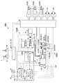
- FIG. 2 is a diagram schematically illustrating an example of a control system according to the present embodiment.
- FIG. 3 is a diagram schematically illustrating an example of an engine and an exhaust gas treatment apparatus according to the present embodiment.
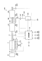
- FIG. 4 is a diagram illustrating an example of a hydraulic system according to the present embodiment.
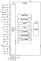
- FIG. 5 is a functional block diagram illustrating an example of a control device according to the present embodiment.
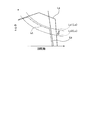
- FIG. 6 is a diagram illustrating an example of a torque diagram of the engine according to the present embodiment.
- FIG. 7 is a flowchart illustrating an example of a method for controlling the work machine according to the present embodiment.
- FIG. 1 is a perspective view illustrating an example of a work machine 1 according to the present embodiment.
- the work machine 1 is a hybrid hydraulic excavator.
- the work machine 1 is appropriately referred to as a hydraulic excavator 1.
- the excavator 1 is driven by a work machine 10, an upper swing body 2 that supports the work machine 10, a lower traveling body 3 that supports the upper swing body 2, an engine 4, and the engine 4.
- an operation device 5 for operating the work machine 10 a control device 100, and an exhaust gas treatment device 200 for treating exhaust gas of the engine 4.
- the engine 4 is an internal combustion engine that is a power source of the excavator 1.
- the engine 4 has an output shaft 4 ⁇ / b> S connected to the generator motor 27 and the hydraulic pump 30.
- the engine 4 is, for example, a diesel engine.
- the engine 4 is accommodated in the machine room 7 of the upper swing body 2.
- the generator motor 27 is connected to the output shaft 4S of the engine 4 and generates power by the operation of the engine 4.
- the generator motor 27 is, for example, a switched reluctance motor.
- the generator motor 27 may be a PM (Permanent Magnet) motor.
- the hydraulic pump 30 is connected to the output shaft 4S of the engine 4 and discharges hydraulic oil by the operation of the engine 4.
- the hydraulic pump 30 includes a first hydraulic pump 31 connected to the output shaft 4S and driven by the engine 4, and a second hydraulic pump 32 connected to the output shaft 4S and driven by the engine 4. Including.
- the hydraulic pump 30 is accommodated in the machine room 7 of the upper swing body 2.
- the work machine 10 is supported by the upper swing body 2.
- the work machine 10 includes a plurality of work machine elements that are relatively movable.
- the work machine element of the work machine 1 includes a bucket 11, an arm 12 connected to the bucket 11, and a boom 13 connected to the arm 12.
- the bucket 11 is rotatably connected to the tip of the arm 12.
- the arm 12 is rotatably connected to the distal end portion of the boom 13.
- the boom 13 is rotatably connected to the upper swing body 2.
- the hydraulic cylinder 20 is operated by hydraulic oil supplied from the hydraulic pump 30.
- the hydraulic cylinder 20 is a hydraulic actuator that generates power for operating the work machine 10.
- the work machine 10 can be operated by the power generated by the hydraulic cylinder 20.
- the hydraulic cylinder 20 includes a bucket cylinder 21 that operates the bucket 11, an arm cylinder 22 that operates the arm 12, and a boom cylinder 23 that operates the boom 13.
- the electric motor 25 is operated by electric power supplied from the generator motor 27.
- the electric motor 25 is an electric actuator that generates power for turning the upper swing body 2.
- the upper-part turning body 2 can turn around the turning axis RX by the power generated by the electric motor 25.
- the hydraulic motor 24 is operated by hydraulic oil supplied from the hydraulic pump 30.
- the hydraulic motor 24 is a hydraulic actuator that generates power for causing the lower traveling body 3 to travel.
- the crawler belt 3 ⁇ / b> C of the lower traveling body 3 can be rotated by the power generated by the hydraulic motor 24.
- the upper-part turning body 2 includes a fuel tank 8 that stores fuel and a hydraulic oil tank 9 that stores hydraulic oil.
- the fuel stored in the fuel tank 8 is supplied to the engine 4.
- the hydraulic oil stored in the hydraulic oil tank 9 is supplied to the hydraulic cylinder 20 and the hydraulic motor 24 via the hydraulic pump 30.
- the operating device 5 is disposed in the cab 6.
- the operating device 5 is operated to drive each of the hydraulic cylinder 20 and the hydraulic motor 24.
- the operating device 5 includes an operating member that is operated by a driver of the excavator 1.
- the operation member includes an operation lever or a joystick. When the operation device 5 is operated, the work machine 10 operates.
- FIG. 2 is a diagram schematically illustrating an example of the control system 1000 according to the present embodiment.
- the control system 1000 is mounted on the excavator 1 and controls the excavator 1.
- Control system 1000 includes a control device 100, a hydraulic system 1000A, and an electric system 1000B.
- the hydraulic system 1000 ⁇ / b> A includes a hydraulic pump 30, a hydraulic circuit 40 through which hydraulic oil discharged from the hydraulic pump 30 flows, a hydraulic cylinder 20 that operates with hydraulic oil supplied from the hydraulic pump 30 via the hydraulic circuit 40, and hydraulic pressure And a hydraulic motor 24 that is operated by hydraulic oil supplied from the hydraulic pump 30 via the circuit 40.
- the output shaft 4S of the engine 4 is connected to the hydraulic pump 30.
- the hydraulic pump 30 When the engine 4 is driven, the hydraulic pump 30 is operated.
- the hydraulic cylinder 20 and the hydraulic motor 24 operate based on the hydraulic oil discharged from the hydraulic pump 30.
- An engine speed sensor 4 ⁇ / b> R that detects the speed [rpm] of the engine 4 is provided in the engine 4.
- the hydraulic pump 30 is a variable displacement hydraulic pump.
- the hydraulic pump 30 is a swash plate hydraulic pump.
- the swash plate 30A of the hydraulic pump 30 is driven by a servo mechanism 30B.
- the capacity [cc / rev] of the hydraulic pump 30 is adjusted by adjusting the angle of the swash plate 30A by the servo mechanism 30B.
- the capacity of the hydraulic pump 30 refers to the discharge amount [cc / rev] of hydraulic oil discharged from the hydraulic pump 30 when the output shaft 4S of the engine 4 connected to the hydraulic pump 30 makes one rotation.
- the swash plate 30A of the hydraulic pump 30 includes a swash plate 31A of the first hydraulic pump 31 and a swash plate 32A of the second hydraulic pump 32.
- the servo mechanism 30B includes a servo mechanism 31B that adjusts the angle of the swash plate 31A of the first hydraulic pump 31, and a servo mechanism 32B that adjusts the angle of the swash plate 32A of the second hydraulic pump 32.
- the electric system 1000B includes a generator motor 27, a capacitor 14, a transformer 14C, a first inverter 15G, a second inverter 15R, and an electric motor 25 that is operated by electric power supplied from the generator motor 27.
- the output shaft 4S of the engine 4 is connected to the generator motor 27.
- the generator motor 27 When the engine 4 is driven, the generator motor 27 is activated.
- the rotor of the generator motor 27 rotates.
- the generator motor 27 When the rotor of the generator motor 27 rotates, the generator motor 27 generates power.
- the generator motor 27 may be connected to the output shaft 4S of the engine 4 through a power transmission mechanism such as PTO (Power Take Off).
- the electric motor 25 operates based on the electric power output from the generator motor 27.
- the electric motor 25 generates power for turning the upper swing body 2.
- a rotation sensor 16 is provided in the electric motor 25.
- the rotation sensor 16 includes, for example, a resolver or a rotary encoder. The rotation sensor 16 detects the rotation angle or rotation speed of the electric motor 25.
- the driver's cab 6 is provided with an operating device 5, a throttle dial 33, and a work mode selector 34 that are operated by the driver.
- the operating device 5 includes an operating member that operates the lower traveling body 3, an operating member that operates the upper swing body 2, and an operating member that operates the work machine 10.
- the hydraulic motor 24 that travels the lower traveling body 3 operates based on the operation of the operation device 5.
- the electric motor 25 that rotates the upper swing body 2 operates based on the operation of the operation device 5.
- the hydraulic cylinder 20 that operates the work machine 10 operates based on the operation of the operation device 5.
- the operation device 5 includes a right operation lever 5R disposed on the right side of the driver seated on the driver's seat 6S and a left operation lever 5L disposed on the left side.
- the operating device 5 has a travel lever (not shown).
- the travel motor 24 is driven by operating the travel lever.
- the control system 1000 includes an operation amount sensor 90 that detects an operation amount of the operation device 5.
- the operation amount sensor 90 drives a bucket operation amount sensor 91 that detects an operation amount of the operation device 5 that is operated to drive the bucket cylinder 21 that operates the bucket 11 and an arm cylinder 22 that operates the arm 12.
- An arm operation amount sensor 92 that detects the operation amount of the operation device 5 that is operated to the boom 13 and a boom operation amount sensor 93 that detects the operation amount of the operation device 5 that is operated to drive the boom cylinder 23 that operates the boom 13. Including.
- the throttle dial 33 is an operation member for setting the fuel injection amount injected into the engine 4.
- the throttle dial 33 sets the upper limit rotational speed Nmax [rpm] of the engine 4.
- the work mode selector 34 is an operation member for setting the output characteristics of the engine 4.
- the maximum output [kW] of the engine 4 is set by the work mode selector 34.
- the control device 100 includes a computer system.
- the control device 100 includes an arithmetic processing device including a processor such as a CPU (Central Processing Unit), a storage device including a memory such as a ROM (Read Only Memory) or a RAM (Random Access Memory), an input / output interface device, Have
- the control device 100 outputs a command signal for controlling the hydraulic system 1000A and the electric system 1000B.
- the control device 100 includes a pump controller 100A that controls the hydraulic system 1000A, a hybrid controller 100B that controls the electric system 1000B, and an engine controller 100C that controls the engine 4.
- the pump controller 100A Based on at least one of the command signal transmitted from the hybrid controller 100B, the command signal transmitted from the engine controller 100C, and the detection signal transmitted from the operation amount sensor 90, the pump controller 100A A command signal for controlling the second hydraulic pump 32 is output.
- the pump controller 100A outputs a command signal for adjusting the capacity [cc / rev] of the hydraulic pump 30.
- the pump controller 100A adjusts the capacity [cc / rev] of the hydraulic pump 30 by outputting a command signal to the servo mechanism 30B and controlling the angle of the swash plate 30A of the hydraulic pump 30.
- the hydraulic pump 30 includes a swash plate angle sensor 30S that detects the angle of the swash plate 30A.
- the inclination angle sensor 30S includes an inclination angle sensor 31S that detects the angle of the swash plate 31A and an inclination angle sensor 32S that detects the angle of the swash plate 32A.
- the detection signal of the swash plate angle sensor 30S is output to the pump controller 100A.
- the pump controller 100A controls the angle of the swash plate 30A by outputting a command signal to the servo mechanism 30B based on the detection signal of the swash plate angle sensor 30S.
- the hydraulic pump 30 is driven by the engine 4.
- the operation per unit time discharged from the hydraulic pump 30 is increased by increasing the rotation speed [rpm] of the engine 4 and increasing the rotation speed per unit time of the output shaft 4S of the engine 4 connected to the hydraulic pump 30.
- the oil discharge flow rate Q [l / min] increases.
- the operation per unit time discharged from the hydraulic pump 30 is reduced when the rotation speed [rpm] of the engine 4 is decreased and the rotation speed per unit time of the output shaft 4S of the engine 4 connected to the hydraulic pump 30 is decreased.
- the oil discharge flow rate Q [l / min] decreases.
- the pump controller 100A outputs a command signal for adjusting each of the capacity [cc / rev] of the first hydraulic pump 31 and the capacity [cc / rev] of the second hydraulic pump 32.
- the pump controller 100A outputs a command signal to the servo mechanism 31B based on the detection signal of the swash plate angle sensor 31S, and controls the angle of the swash plate 31A of the first hydraulic pump 31 to thereby control the first hydraulic pump 31. Adjust the capacity [cc / rev].
- the pump controller 100A outputs a command signal to the servo mechanism 32B based on the detection signal of the swash plate angle sensor 32S, and controls the angle of the swash plate 32A of the second hydraulic pump 32, whereby the second hydraulic pump 32 Adjust the capacity [cc / rev].
- the hydraulic oil discharge flow rate Q [l / min] discharged from the hydraulic pump 30 is discharged from the second hydraulic pump 32 and the hydraulic oil discharge flow rate Q1 [l / min] discharged from the first hydraulic pump 31. Hydraulic fluid discharge flow rate Q2 [l / min]. As the rotational speed of the engine 4 increases and the rotational speed per unit time of the output shaft 4S of the engine 4 connected to the first hydraulic pump 31 and the second hydraulic pump 32 increases, the discharge of the first hydraulic pump 31 The flow rate Q1 [l / min] and the discharge flow rate Q2 [l / min] of the second hydraulic pump 32 increase.
- the maximum discharge flow rate Qmax [l / min] of the hydraulic pump 30 includes the maximum discharge flow rate Q1max [l / min] of the first hydraulic pump 31 and the maximum discharge flow rate Q2max [l / min] of the second hydraulic pump 32. .
- the first hydraulic pump 31 discharges hydraulic oil at the maximum discharge flow rate Q1max.
- the second hydraulic pump 32 discharges hydraulic oil at the maximum discharge flow rate Q2max.
- the maximum discharge flow rate Q1max and the maximum discharge flow rate Q2max are equal.
- the hybrid controller 100B controls the electric motor 25 based on the detection signal of the rotation sensor 16.
- the electric motor 25 operates based on the electric power supplied from the generator motor 27 or the battery 14.
- the hybrid controller 100B performs control of power transfer between the transformer 14C and the first inverter 15G and the second inverter 15R, and control of power transfer between the transformer 14C and the capacitor 14. To do.
- the hybrid controller 100B also generates the generator motor 27 and the electric motor 25 based on the detection signals of the temperature sensors provided in the generator motor 27, the electric motor 25, the battery 14, the first inverter 15G, and the second inverter 15R. The respective temperatures of the battery 14, the first inverter 15G, and the second inverter 15R are adjusted.
- the hybrid controller 100 ⁇ / b> B performs charge / discharge control of the battery 14, power generation control of the generator motor 27, and assist control of the engine 4 by the generator motor 27.
- the engine controller 100C generates a command signal based on the set value of the throttle dial 33, and outputs the command signal to the common rail control unit 29 provided in the engine 4.
- the common rail control unit 29 adjusts the fuel injection amount for the engine 4 based on the command signal transmitted from the engine controller 100C.
- FIG. 3 is a diagram schematically illustrating an example of the engine 4 and the exhaust gas treatment device 200 according to the present embodiment.
- the exhaust gas processing device 200 processes the exhaust gas of the engine 4.
- the exhaust gas treatment apparatus 200 includes a urea SCR (Selective Catalytic Reduction) system that reduces and purifies nitrogen oxides (NOx) contained in the exhaust gas using a selective catalyst and a reducing agent.
- NOx nitrogen oxides
- the engine 4 has a fuel injection device 17.
- the fuel injection device 17 injects fuel into the combustion chamber of the engine 4.
- the fuel injection device 17 is a common rail system including a pressure accumulating chamber 17A and an injector 17B.
- the fuel injection device 17 is controlled by the control device 50 via the common rail control unit 29.
- the engine 4 is connected to each of the intake pipe 18 and the exhaust pipe 19.
- the inlet of the intake pipe 18 is connected to an air cleaner 35 that collects foreign substances in the air.
- the outlet of the intake pipe 18 is connected to the intake port of the engine 4.
- the exhaust gas treatment device 200 is connected to the exhaust port of the engine 4 via the exhaust pipe 19.
- the exhaust gas treatment device 200 purifies the exhaust gas discharged from the engine 4.
- the exhaust gas treatment device 200 reduces NOx (nitrogen oxide) contained in the exhaust gas.
- the exhaust gas treatment device 20 is connected to the exhaust pipe 19, and is connected to the filter unit 201 via a pipe line 202 for collecting particulates contained in the exhaust gas, and a reduction catalyst 203 that reduces NOx contained in the exhaust gas.
- a reducing agent supply device 204 for supplying the reducing agent R.
- the filter unit 201 includes a particulate filter (Diesel Particulate Filter: DPF) and collects particulates contained in the exhaust gas.
- DPF Diesel Particulate Filter
- the reduction catalyst 203 reduces NOx contained in the exhaust gas by the reducing agent R supplied from the reducing agent supply device 204.
- the reduction catalyst 203 converts NOx into nitrogen and water by the reducing agent R.
- a vanadium catalyst or a zeolite catalyst is used as the reduction catalyst 203.
- the reducing agent supply device 204 supplies the reducing agent R to the pipe line 202.
- the reducing agent R is urea (urea water).
- the reducing agent supply device 204 is connected to the reducing agent tank 205 that contains the reducing agent R, the supply pipe 206 connected to the reducing agent tank 205, the supply pump 207 provided in the supply pipe 206, and the supply pipe 207. And an injection nozzle 208.
- the supply pump 207 pumps the reducing agent R stored in the reducing agent tank 205 to the injection nozzle 208.
- the injection nozzle 208 injects the reducing agent R supplied from the reducing agent tank 205 into the pipe line 202.
- the supply amount (injection amount) of the reducing agent R by the reducing agent supply device 204 is controlled by the control device 100.
- the reducing agent R supplied to the inside of the pipe line 202 is decomposed by the heat of the exhaust gas and changed to ammonia.
- NOx and ammonia undergo a catalytic reaction and are converted into nitrogen and water.
- the reducing agent tank 209 of the reducing agent supply device 204 is provided with a reducing agent sensor 209 that detects the amount (water level) of the reducing agent R.
- the control system 1000 includes an exhaust gas sensor 300 for detecting the state of the engine 4.
- the exhaust gas sensor 300 detects the state of the engine 4 by detecting the state of the exhaust gas from the engine 4.
- the state of the exhaust gas includes at least one of the concentration of NOx contained in the exhaust gas, the pressure of the exhaust gas, the temperature of the exhaust gas, and the flow rate of the exhaust gas.
- the reducing agent supply device 204 adjusts the supply amount of the reducing agent R supplied to the reduction catalyst 203 based on the detection signal of the exhaust gas sensor 300.
- the exhaust gas sensor 300 includes a NOx sensor 301 that detects the concentration of NOx contained in the exhaust gas, a pressure sensor 302 and a pressure sensor 304 that detect the pressure of the exhaust gas, and a temperature sensor 303 that detects the temperature of the exhaust gas. including.
- the NOx sensor 301 detects the concentration of NOx in the exhaust gas in the exhaust pipe 19.
- the pressure sensor 302 detects the pressure of the exhaust gas in the pipe line 202.
- the temperature sensor 303 detects the temperature of the exhaust gas in the pipe line 202.
- the pressure sensor 304 detects the pressure of the exhaust gas that has passed through the reduction catalyst 203.
- the exhaust gas sensor 300 includes an intake flow rate sensor 305 that detects the flow rate of air taken into the engine 4 via the intake pipe 18. The flow rate of exhaust gas is determined based on the flow rate of air sucked into the engine 4.
- the intake flow rate sensor 305 functions as an exhaust gas flow rate sensor.
- the detection signal of the NOx sensor 301, the detection signal of the pressure sensor 302, the detection signal of the temperature sensor 303, the detection signal of the pressure sensor 304, and the detection signal of the intake flow rate sensor 305 are output to the control device 100.
- the control device 100 controls the supply amount of the reducing agent R supplied to the reduction catalyst 203 based on at least the detection signal of the NOx sensor 301 and the detection signal of the pressure sensor 302. For example, the control device 100 calculates the flow rate of exhaust gas supplied from the pipe line 202 to the reduction catalyst 203 based on the detection signal of the pressure sensor 302. The control device 100 calculates the NOx flow rate in the pipeline 202 based on the exhaust gas flow rate in the pipeline 202 and the NOx concentration of the exhaust gas detected by the NOx sensor 301. The control device 100 determines the supply amount of the reducing agent R supplied to the reduction catalyst 203 based on the flow rate of NOx in the pipe line 202.
- the control device 100 may calculate the flow rate of the exhaust gas in the pipe line 202 based on the detection signal of the intake flow rate sensor 305 and the fuel injection amount supplied from the fuel injection device 17 to the engine 4.
- the control device 100 supplies the reducing agent 203 to the reduction catalyst 203 based on the detection signal of the NOx sensor 301, the detection signal of the pressure sensor 302, the detection signal of the temperature sensor 303, and the detection signal of the pressure sensor 304.
- the supply amount of R may be controlled.
- the exhaust gas sensor 300 includes an atmospheric pressure sensor 306, an outside air temperature sensor 307, and a coolant temperature sensor 308.
- the atmospheric pressure sensor 306 detects an atmospheric pressure that is an environmental pressure in which the engine 4 and the exhaust gas treatment apparatus 200 are used.
- An outside air temperature that is an environmental temperature in which the engine 4 and the exhaust gas treatment device 200 are used is detected.
- the coolant temperature sensor 308 detects the temperature of the coolant that cools the engine 4.
- the NOx sensor 301 requires a certain amount of time from when the engine 4 is started and the NOx sensor 301 is activated until it becomes a state where NOx can be detected.
- the NOx sensor 301 needs to keep the sensing unit at a high temperature due to its structure. Therefore, it takes time until the NOx sensor 301 can detect the NOx concentration after the engine 4 is started.
- the control device 100 for example, a detection signal of the engine speed sensor 4R, a detection signal of the atmospheric pressure sensor 306, a detection signal of the outside air temperature sensor 307, Based on the detection signal of the coolant temperature sensor 308, the concentration of NOx is estimated, and based on the estimated concentration of NOx, the supply amount of the reducing agent R supplied from the reducing agent supply device 204 to the reduction catalyst 203 is determined. Control.
- FIG. 4 is a diagram illustrating an example of a hydraulic system 1000A according to the present embodiment.
- the hydraulic system 1000A is supplied with a hydraulic pump 30 that discharges hydraulic oil, a hydraulic circuit 40 through which hydraulic oil discharged from the hydraulic pump 30 flows, and hydraulic oil discharged from the hydraulic pump 30 via the hydraulic circuit 40.
- a hydraulic cylinder 20, a main operation valve 60 that adjusts the direction of hydraulic oil supplied to the hydraulic cylinder 20 and the hydraulic oil distribution flow rate Qa, and a pressure compensation valve 70 are provided.
- the hydraulic pump 30 includes a first hydraulic pump 31 and a second hydraulic pump 32.
- the hydraulic cylinder 20 includes a bucket cylinder 21, an arm cylinder 22, and a boom cylinder 23.
- the main operation valve 60 is supplied from the hydraulic pump 30 to the arm cylinder 22 and the first main operation valve 61 that adjusts the direction of the hydraulic oil supplied from the hydraulic pump 30 to the bucket cylinder 21 and the hydraulic oil distribution flow rate Qabk.
- a second main operation valve 62 that adjusts the direction of hydraulic oil and the hydraulic oil distribution flow rate Qaar, and a third main valve that adjusts the direction of hydraulic oil supplied from the hydraulic pump 30 to the boom cylinder 23 and the hydraulic oil distribution flow rate Qabm.
- an operation valve 63 is a slide spool type directional control valve.
- the pressure compensation valve 70 includes a pressure compensation valve 71, a pressure compensation valve 72, a pressure compensation valve 73, a pressure compensation valve 74, a pressure compensation valve 75, and a pressure compensation valve 76.
- the hydraulic system 1000A is provided in a merging channel 55 that connects the first hydraulic pump 31 and the second hydraulic pump 32, and includes a merging state in which the merging channel 55 is opened and a shunting state in which the merging channel 55 is closed.
- the hydraulic circuit 40 includes a first hydraulic pump passage 41 connected to the first hydraulic pump 31 and a second hydraulic pump passage 42 connected to the second hydraulic pump 32.
- the hydraulic circuit 40 includes a first supply channel 43 and a second supply channel 44 connected to the first hydraulic pump channel 41, a third supply channel 45 and a second supply channel 45 connected to the second hydraulic pump channel 42. 4 supply flow path 46.
- the first hydraulic pump flow path 41 is branched into a first supply flow path 43 and a second supply flow path 44 at the first branch portion Br1.
- the second hydraulic pump flow path 42 is branched into a third supply flow path 45 and a fourth supply flow path 46 at the fourth branch portion Br4.
- the hydraulic circuit 40 includes a first branch channel 47 and a second branch channel 48 connected to the first supply channel 43, and a third branch channel 49 and a fourth branch connected to the second supply channel 44. And a flow path 50.
- the first supply channel 43 is branched into a first branch channel 47 and a second branch channel 48 at the second branch portion Br2.
- the second supply channel 44 is branched into a third branch channel 49 and a fourth branch channel 50 at the third branch part Br3.
- the hydraulic circuit 40 includes a fifth branch channel 51 connected to the third supply channel 45 and a sixth branch channel 52 connected to the fourth supply channel 46.
- the first main operation valve 61 is connected to the first branch channel 47 and the third branch channel 49.
- the second main operation valve 62 is connected to the second branch channel 48 and the fourth branch channel 50.
- the third main operation valve 63 is connected to the fifth branch channel 51 and the sixth branch channel 52.
- the hydraulic circuit 40 connects the first bucket flow path 21A that connects the first main operation valve 61 and the cap-side space 21C of the bucket cylinder 21, and the first main operation valve 61 and the rod-side space 21L of the bucket cylinder 21. Second bucket flow path 21B.
- the hydraulic circuit 40 connects the first arm flow path 22A that connects the second main operation valve 62 and the rod side space 22L of the arm cylinder 22, and the second main operation valve 62 and the cap side space 22C of the arm cylinder 22. Second arm channel 22B.
- the hydraulic circuit 40 connects the first boom flow path 23A that connects the third main operation valve 63 and the cap side space 23C of the boom cylinder 23, and the third main operation valve 63 and the rod side space 23L of the boom cylinder 23. Second boom channel 23B.
- the cap side space of the hydraulic cylinder 20 is a space between the cylinder head cover and the piston.
- the rod side space of the hydraulic cylinder 20 is a space in which the piston rod is disposed.
- the hydraulic oil is supplied to the cap side space 21C of the bucket cylinder 21 and the bucket cylinder 21 extends, whereby the bucket 11 performs excavation.
- the hydraulic oil is supplied to the rod-side space 21L of the bucket cylinder 21, and the bucket 11 performs a dumping operation when the bucket cylinder 21 is retracted.
- the working oil is supplied to the cap-side space 22C of the arm cylinder 22 and the arm 12 extends, so that the arm 12 performs an excavation operation.
- the arm 12 performs a dumping operation.
- the first main operation valve 61 supplies hydraulic oil to the bucket cylinder 21 and collects the hydraulic oil discharged from the bucket cylinder 21.
- the spool of the first main operation valve 61 stops the supply of hydraulic oil to the bucket cylinder 21 to stop the bucket cylinder 21, and the first branch flow so that the hydraulic oil is supplied to the cap side space 21C.
- the second position PT2 that connects the path 21B and retracts the bucket cylinder 21 is movable.
- the first main operation valve 61 is operated so that the bucket cylinder 21 is at least one of a stopped state, an extended state, and a retracted state.
- the second main operation valve 62 supplies hydraulic oil to the arm cylinder 22 and collects the hydraulic oil discharged from the arm cylinder 22.
- the second main operation valve 62 has the same structure as the first main operation valve 61.
- the spool of the second main operation valve 62 has a stop position where the supply of hydraulic oil to the arm cylinder 22 is stopped to stop the arm cylinder 22, and a fourth branch flow path so that the hydraulic oil is supplied to the cap side space 22C. 50 and the second arm channel 22B are connected to each other to extend the arm cylinder 22, and the second branch channel 48 and the first arm channel 22A are supplied to the rod side space 22L.
- the second main operation valve 62 is operated so that the arm cylinder 22 is in at least one of a stopped state, an extended state, and a retracted state.
- the third main operation valve 63 supplies hydraulic oil to the boom cylinder 23 and collects the hydraulic oil discharged from the boom cylinder 23.
- the third main operation valve 63 has a structure equivalent to that of the first main operation valve 61.
- the spool of the third main operation valve 63 has a stop position where the supply of hydraulic oil to the boom cylinder 23 is stopped to stop the boom cylinder 23, and a fifth branch flow path so that the hydraulic oil is supplied to the cap side space 23C.
- 51 and the first boom passage 23A are connected to each other to extend the boom cylinder 23, and the sixth branch passage 52 and the second boom passage 23B are supplied to the rod-side space 23L.
- the third main operation valve 63 is operated so that the boom cylinder 23 is in at least one of a stopped state, an extended state, and a retracted state.
- the first main operation valve 61 is operated by the operation device 5.
- a pilot pressure determined based on the operation amount of the operation device 5 acts on the first main operation valve 61.
- the direction of the hydraulic oil supplied from the first main operation valve 61 to the bucket cylinder 21 and the distribution flow Qabk of the hydraulic oil are determined.
- the rod of the bucket cylinder 21 moves in a moving direction corresponding to the direction of the supplied hydraulic oil, and operates at a cylinder speed corresponding to the distributed flow rate Qabk of the supplied hydraulic oil.
- the bucket 11 is operated based on the moving direction of the bucket cylinder 21 and the cylinder speed.
- the second main operation valve 62 is operated by the operation device 5.
- a pilot pressure determined based on the operation amount of the operation device 5 acts on the second main operation valve 62.
- the direction of the hydraulic oil supplied from the second main operation valve 62 to the arm cylinder 22 and the distribution flow rate Qaar of the hydraulic oil are determined.
- the rod of the arm cylinder 22 moves in a movement direction corresponding to the direction of the supplied hydraulic oil, and operates at a cylinder speed corresponding to the distributed flow rate Qaar of the supplied hydraulic oil.
- the arm 12 operates based on the moving direction of the arm cylinder 22 and the cylinder speed.
- the third main operation valve 63 is operated by the operation device 5.
- a pilot pressure determined based on the operation amount of the operation device 5 acts on the third main operation valve 63.
- the direction of the hydraulic oil supplied from the third main operation valve 63 to the boom cylinder 23 and the distribution flow Qabm of the hydraulic oil are determined.
- the rod of the boom cylinder 23 moves in a moving direction corresponding to the direction of the supplied hydraulic oil, and operates at a cylinder speed corresponding to the distributed flow rate Qabm of the supplied hydraulic oil.
- the boom 13 is operated based on the moving direction of the boom cylinder 23 and the cylinder speed.
- the first hydraulic pump flow path 41 and the second hydraulic pump flow path 42 are connected by a merging flow path 55.
- the merge channel 55 is a channel that connects the first hydraulic pump 31 and the second hydraulic pump 32.
- the merge channel 55 connects the first hydraulic pump 31 and the second hydraulic pump 32 via the first hydraulic pump channel 41 and the second hydraulic pump channel 42.
- the first joining / dividing valve 67 is an opening / closing device that opens and closes the joining flow path 55.
- the first merging / dividing valve 67 opens and closes the merging channel 55 to switch between a merging state where the merging channel 55 is opened and a merging state where the merging channel 55 is closed.
- the first joining / dividing valve 67 is a switching valve. As long as the merge channel 55 can be opened and closed, the switching device that opens and closes the merge channel 55 may not be a switching valve.
- the spool of the first merging / dividing valve 67 opens the merging passage 55 and connects the first hydraulic pump passage 41 and the second hydraulic pump passage 42, and the merging passage 55 is closed to close the first hydraulic pressure. It is possible to move between the diversion positions separating the pump flow path 41 and the second hydraulic pump flow path 42.
- the control device 100 controls the first merging / dividing valve 67 so that the first hydraulic pump flow path 41 and the second hydraulic pump flow path 42 are in either the merging state or the diversion state.
- the merging state means that the merging channel 55 that connects the first hydraulic pump channel 41 and the second hydraulic pump channel 42 is opened in the first merging / dividing valve 67, thereby 2 hydraulic pump flow path 42 is connected via a merging flow path 55, and the hydraulic oil discharged from the first hydraulic pump flow path 41 and the hydraulic oil discharged from the second hydraulic pump flow path 42 are in the first combination.
- the diversion state means that the merging channel 55 connecting the first hydraulic pump channel 41 and the second hydraulic pump channel 42 is closed by the first merging / dividing valve 67, so The second hydraulic pump flow path 42 is separated, and the hydraulic oil discharged from the first hydraulic pump flow path 41 and the hydraulic oil discharged from the second hydraulic pump flow path 42 are separated.
- the hydraulic oil discharged from the first hydraulic pump 31 is supplied to the bucket cylinder 21 and the arm cylinder 22, and the hydraulic oil discharged from the second hydraulic pump 32 is supplied to the boom cylinder 23.
- the first hydraulic actuator to which the hydraulic oil discharged from the first hydraulic pump 31 is supplied in the diversion state is the bucket cylinder 21 that drives the bucket 11 and the arm cylinder 22 that drives the arm 12. is there.
- the second hydraulic actuator to which the hydraulic oil discharged from the second hydraulic pump 32 is supplied in the diversion state is a boom cylinder 23 that drives the boom 13. In the diversion state, the hydraulic oil discharged from the first hydraulic pump 31 is not supplied to the boom cylinder 23. In the diversion state, the hydraulic oil discharged from the second hydraulic pump 32 is not supplied to the bucket cylinder 21 and the arm cylinder 22.
- the hydraulic oil discharged from each of the first hydraulic pump 31 and the second hydraulic pump 32 flows through the first hydraulic pump channel 41, the second hydraulic pump channel 42, the first main operation valve 61, After passing through each of the two main operation valves 62 and the third main operation valve 63, it is supplied to each of the bucket cylinder 21, the arm cylinder 22, and the boom cylinder 23.
- the hydraulic oil discharged from the first hydraulic pump 31 passes through each of the first hydraulic pump flow path 41, the first main operation valve 61, and the second main operation valve 62, and then the bucket cylinder 21. And supplied to the arm cylinder 22. Further, in the diversion state, the hydraulic oil discharged from the second hydraulic pump 32 is supplied to the boom cylinder 23 after passing through the second hydraulic pump flow path 42 and the third main operation valve 63.
- the hydraulic system 1000 ⁇ / b> A is provided between the shuttle valve 701 provided between the first main operation valve 61 and the second main operation valve 62, and between the second combined flow valve 68 and the third main operation valve 63. And a shuttle valve 702.
- the hydraulic system 1000 ⁇ / b> A includes a shuttle valve 701 and a second combined / dividing valve 68 connected to the shuttle valve 702.
- the second combined / dividing valve 68 has a maximum load sensing pressure (LS pressure) obtained by reducing the operating oil supplied to each of the bucket cylinder 21, the arm cylinder 22, and the boom cylinder 23 by the shuttle valve 701 and the shuttle valve 702. Select.
- the load sensing pressure is a pilot pressure used for pressure compensation.
- the maximum LS pressure is selected from the bucket cylinder 21 to the boom cylinder 23, and the pressure compensation valve 70 and the first hydraulic pump 31 of each of the bucket cylinder 21 to the boom cylinder 23 are selected.
- the servo mechanism 31B and the servo mechanism 32B of the second hydraulic pump 32 are supplied.
- the maximum LS pressure between the bucket cylinder 21 and the arm cylinder 22 is supplied to the pressure compensation valve 70 of the bucket cylinder 21 and the arm cylinder 22 and the servo mechanism 31B of the first hydraulic pump 31. Then, the LS pressure of the boom cylinder 23 is supplied to the pressure compensation valve 70 of the boom cylinder 23 and the servo mechanism 32B of the second hydraulic pump 32.
- the shuttle valve 701 and the shuttle valve 702 select a pilot pressure indicating the maximum value from among the pilot pressures output from the first main operation valve 61, the second main operation valve 62, and the third main operation valve 63.
- the selected pilot pressure is supplied to the pressure compensation valve 70 and the servo mechanisms (31B, 32B) of the hydraulic pump 30 (31, 32).
- the hydraulic system 1000 ⁇ / b> A includes a load pressure sensor 80 that detects the pressure PL of the hydraulic oil in the hydraulic cylinder 20.
- the hydraulic oil pressure PL in the hydraulic cylinder 20 is a load pressure of the hydraulic oil supplied to the hydraulic cylinder 20.
- a detection signal of the load pressure sensor 80 is output to the control device 100.
- the load pressure sensor 80 includes a bucket load pressure sensor 81 that detects the hydraulic oil pressure PLbk of the bucket cylinder 21, an arm load pressure sensor 82 that detects the hydraulic oil pressure PLar of the arm cylinder 22, and a boom. And a boom load pressure sensor 83 that detects the pressure PLbm of the hydraulic oil in the cylinder 23.
- the bucket load pressure sensor 81 is provided in the first bucket flow path 21A, and is provided in the bucket load pressure sensor 81C that detects the hydraulic oil pressure PLbkc in the cap side space 21C of the bucket cylinder 21 and the second bucket flow path 21B. And a bucket load pressure sensor 81L for detecting the pressure PLbkl of the hydraulic oil in the rod side space 21L of the bucket cylinder 21.
- the arm load pressure sensor 82 is provided in the second arm flow path 22B, and is provided in the first arm flow path 22A and the arm load pressure sensor 82C that detects the pressure PLArc of the hydraulic oil in the cap side space 22C of the arm cylinder 22. , And an arm load pressure sensor 82L for detecting the hydraulic pressure PParl in the rod side space 22L of the arm cylinder 22.
- the boom load pressure sensor 83 is provided in the first boom flow path 23A, and is provided in the boom load pressure sensor 83C that detects the hydraulic oil pressure PLbmc in the cap side space 23C of the boom cylinder 23, and the second boom flow path 23B. And a boom load pressure sensor 83L for detecting the pressure PLbml of the hydraulic oil in the rod side space 23L of the boom cylinder 23.
- the hydraulic system 1000A includes a discharge pressure sensor 800 that detects the discharge pressure P of the hydraulic oil discharged from the hydraulic pump 30.
- a detection signal of the discharge pressure sensor 800 is output to the control device 100.
- the discharge pressure sensor 800 is provided between the first hydraulic pump 31 and the first hydraulic pump flow path 41, and detects a discharge pressure sensor 801 that detects the discharge pressure P1 of the hydraulic oil discharged from the first hydraulic pump 31.
- a discharge pressure sensor 802 that is provided between the second hydraulic pump 32 and the second hydraulic pump flow path 42 and detects the discharge pressure P2 of the hydraulic oil discharged from the second hydraulic pump 32 is included.
- the pressure compensation valve 70 has a selection port for selecting communication, throttling, and blocking.
- the pressure compensation valve 70 includes a throttle valve that enables switching between cutoff, throttle, and communication with self-pressure.
- the pressure compensation valve 70 is intended to compensate the flow distribution according to the ratio of the metering opening area of each main operation valve 60 even when the load pressure of each hydraulic cylinder 20 is different.
- the pressure compensating valve 70 has a low load pressure hydraulic pressure so that the outlet pressure of the main operating valve 60 of the hydraulic cylinder 20 with low load pressure is equal to the outlet pressure of the main operating valve 60 of the hydraulic cylinder 20 with maximum load pressure.
- the pressure compensation valve 70 includes a pressure compensation valve 71 and a pressure compensation valve 72 connected to the first main operation valve 61, a pressure compensation valve 73 and a pressure compensation valve 74 connected to the second main operation valve 62, a third A pressure compensation valve 75 and a pressure compensation valve 76 connected to the main operation valve 63 are included.
- the pressure compensation valve 71 has a differential pressure across the first main operation valve 61 in a state in which the first branch flow path 47 and the first bucket flow path 21A are connected so that hydraulic oil is supplied to the cap-side space 21C. Compensate metering differential pressure).
- the pressure compensation valve 72 has a differential pressure across the first main operation valve 61 in a state in which the third branch flow path 49 and the second bucket flow path 21B are connected so that hydraulic oil is supplied to the rod side space 21L. Compensate metering differential pressure).
- the pressure compensation valve 73 has a differential pressure across the second main operation valve 62 in a state where the second branch flow path 48 and the first arm flow path 22A are connected so that hydraulic oil is supplied to the rod side space 22L. Compensate metering differential pressure).
- the pressure compensation valve 74 has a differential pressure across the second main operation valve 62 in a state where the fourth branch flow path 50 and the second arm flow path 22B are connected so that hydraulic oil is supplied to the cap side space 22C. Compensate metering differential pressure).
- the differential pressure across the main operation valve 60 (metering differential pressure) is the pressure between the inlet port corresponding to the hydraulic pump 30 side of the main operation valve 60 and the pressure of the outlet port corresponding to the hydraulic cylinder 20 side.
- the difference is the pressure difference for metering the flow rate.
- each of the bucket cylinder 21 and the arm cylinder 22 is provided.
- the hydraulic oil can be distributed at a flow rate corresponding to the operation amount of the operation device 5.
- the pressure compensation valve 70 can supply a flow rate based on the operation regardless of the loads of the plurality of hydraulic cylinders 20. For example, when a high load is applied to the bucket cylinder 21 and a light load is applied to the arm cylinder 22, the pressure compensation valve 70 (73, 74) disposed on the light load side is changed from the first main operation valve 61 to the bucket cylinder.
- the hydraulic oil is supplied from the second main operation valve 62 to the arm cylinder 22 regardless of the metering differential pressure ⁇ P1 generated when the hydraulic oil is supplied to the engine 21, the flow rate based on the operation amount of the second main operation valve 62 is increased.
- the metering differential pressure ⁇ P2 on the arm cylinder 22 side which is the light load side, is compensated so that the metering differential pressure ⁇ P1 on the bucket cylinder 21 side becomes substantially the same pressure.
- the pressure compensation valve 70 (71, 72) disposed on the light load side is moved from the second main operation valve 62 to the arm cylinder 22.
- a flow rate based on the operation amount of the first main operation valve 61 is supplied.
- the hydraulic circuit 40 has an unload valve 69.
- the hydraulic pump 30 discharges hydraulic oil at a flow rate corresponding to the minimum capacity.
- the hydraulic oil discharged from the hydraulic pump 30 when the hydraulic cylinder 20 is not driven is discharged (unloaded) through the unload valve 69.
- FIG. 5 is a functional block diagram illustrating an example of the control device 100 according to the present embodiment.
- the control device 100 includes a computer system.
- the control device 100 includes an arithmetic processing device 101, a storage device 102, and an input / output interface device 103.
- the control device 100 is connected to the first combined / divided valve 67 and the second combined / divided valve 68 and outputs a command signal to the first combined / divided valve 67 and the second combined / divided valve 68.
- the control device 100 is connected to the fuel injection device 17 (common rail control unit 29) and outputs a command signal to the fuel injection device 17.
- control device 100 determines the load pressure sensor 80 that detects the pressure PL of the hydraulic cylinder 20, the discharge pressure sensor 800 that detects the discharge pressure P of the hydraulic oil discharged from the hydraulic pump 30, and the operation amount S of the operation device 5.
- the operation amount sensor 90 to be detected, the engine speed sensor 4R, the reducing agent sensor 209, and the exhaust gas sensor 300 are connected to each other.
- the operation amount sensor 90 (91, 92, 93) is a pressure sensor.
- the pilot pressure acting on the first main operating valve 61 changes based on the operation amount Sbk of the operating device 5.
- the pilot pressure acting on the second main operating valve 62 changes based on the operation amount Sar of the operating device 5.
- the pilot pressure acting on the third main operating valve 63 changes based on the operation amount Sbm of the operating device 5.
- the bucket operation amount sensor 91 detects a pilot pressure that acts on the first main operation valve 61 when the operation device 5 is operated to drive the bucket cylinder 21.
- the arm operation amount sensor 92 detects a pilot pressure that acts on the second main operation valve 62 when the operation device 5 is operated to drive the arm cylinder 22.
- the boom operation amount sensor 93 detects a pilot pressure that acts on the third main operation valve 63 when the operation device 5 is operated to drive the boom cylinder 23.
- the arithmetic processing unit 101 includes a distribution flow rate calculation unit 112, a determination unit 114, a determination unit 116, a combined / divergence control unit 118, an exhaust gas processing control unit 120, and an engine control unit 122.
- the distribution flow rate calculation unit 112 has a plurality of hydraulic oil pressures PL based on the hydraulic pressures PL of the hydraulic cylinders 20 and an operation amount S of the operating device 5 operated to drive the hydraulic cylinders 20.
- the distribution flow rate Qa of the hydraulic oil supplied to each of the hydraulic cylinders 20 is calculated.
- the distribution flow rate calculation unit 112 is based on the hydraulic oil pressure PL of the hydraulic cylinder 20, the operation amount S of the operating device 5, and the hydraulic oil discharge pressure P discharged from the hydraulic pump 30.
- the distribution flow rate Qa is calculated.
- the pressure PL of the hydraulic oil in the hydraulic cylinder 20 is detected by a load pressure sensor 80.
- the distribution flow rate calculation unit 112 acquires the hydraulic oil pressure PLbk of the bucket cylinder 21 from the bucket load pressure sensor 81, acquires the hydraulic oil pressure PLar of the arm cylinder 22 from the arm load pressure sensor 82, and the boom load pressure sensor 83. From the hydraulic oil pressure PLbm of the boom cylinder 23.
- the operation amount S of the operation device 5 is detected by the operation amount sensor 90.
- the distribution flow rate calculation unit 112 acquires the operation amount Sbk of the operation device 5 operated to drive the bucket cylinder 21 from the bucket operation amount sensor 91 and operates to drive the arm cylinder 22 from the arm operation amount sensor 92.
- the operation amount Sar of the operation device 5 to be operated is acquired, and the operation amount Sbm of the operation device 5 operated to drive the boom cylinder 23 is acquired from the boom operation amount sensor 93.
- the discharge pressure P of the hydraulic oil of the hydraulic pump 30 is detected by a discharge pressure sensor 800.
- the distribution flow rate calculation unit 112 acquires the discharge pressure P1 of the hydraulic oil of the first hydraulic pump 31 from the discharge pressure sensor 801, and acquires the discharge pressure P2 of the hydraulic oil of the second hydraulic pump 32 from the discharge pressure sensor 802.
- the distribution flow rate calculation unit 112 includes the hydraulic pressure PL (PLbk, PLar, PLbm) of each of the plurality of hydraulic cylinders 20 (21, 22, 23) and each of the plurality of hydraulic cylinders 20 (21, 22, 23). Based on the operation amount S (Sbk, Sar, Sbm) of the operating device 5 operated to drive the engine, the distribution flow rate of the hydraulic oil supplied to each of the plurality of hydraulic cylinders 20 (21, 22, 23) Qa (Qabk, Qaar, Qabm) is calculated.
- the distribution flow rate calculation unit 112 calculates the distribution flow rate Qa based on the equation (1).
- Qd is a required flow rate of hydraulic oil in the hydraulic cylinder 20.
- P is a discharge pressure of hydraulic oil discharged from the hydraulic pump 30.
- PL is the load pressure of the hydraulic oil in the hydraulic cylinder 20.
- ⁇ PC is a set differential pressure between the inlet side and the outlet side of the main operation valve 60. In the present embodiment, the differential pressure between the inlet side and the outlet side of the main operation valve 60 is set to the set differential pressure ⁇ PC.
- the set differential pressure ⁇ PC is set in advance for each of the first main operation valve 61, the second main operation valve 62, and the third main operation valve 63, and is stored in the storage device 102.
- the distribution flow rate Qabk of the bucket cylinder 21, the distribution flow rate Qaar of the arm cylinder 22, and the distribution flow rate Qabm of the boom cylinder 23 are calculated based on the equations (2), (3), and (4), respectively.
- Qabk Qdbk ⁇ ⁇ ⁇ (P ⁇ PLbk) / ⁇ PC ⁇ (2)
- Qaar Qdar ⁇ ⁇ ⁇ (P-PLar) / ⁇ PC ⁇ (3)
- Qabm Qdbm ⁇ ⁇ ⁇ (P ⁇ PLbm) / ⁇ PC ⁇ (4)
- Qdbk is a required flow rate of the hydraulic oil in the bucket cylinder 21.
- PLbk is the pressure of the hydraulic oil in the bucket cylinder 21.
- Qdar is a required flow rate of the hydraulic oil in the arm cylinder 22.
- PLar is the pressure of the hydraulic oil in the arm cylinder 22.
- Qdbm is the required flow rate of the hydraulic oil for the boom cylinder 23.
- PLbm is the load pressure of the hydraulic oil in the boom cylinder 23.
- the set differential pressure ⁇ PC between the inlet side and the outlet side of 63 is the same value.
- the required flow rate Qd (Qdbk, Qdar, Qdbm) is calculated based on the operation amount S (Sbk, Sar, Sbm) of the controller device 5.
- the required flow rate Qd (Qdbk, Qdar, Qdbm) is calculated based on the pilot pressure detected by the operation amount sensor 90 (91, 92, 93).
- the operation amount S (Sbk, Sar, Sbm) of the operation device 5 and the pilot pressure detected by the operation amount sensor 90 (91, 92, 93) correspond one-to-one.
- the distribution flow rate calculation unit 112 converts the pilot pressure detected by the operation amount sensor 90 into the spool stroke of the main operation valve 60, and calculates the required flow rate Qd based on the spool stroke.
- the first correlation data indicating the relationship between the pilot pressure and the spool stroke of the main operation valve 60 and the second correlation data indicating the relationship between the spool stroke of the main operation valve 60 and the required flow rate Qd are known data, and are stored in the storage device. 102.
- Each of the first correlation data indicating the relationship between the pilot pressure and the spool stroke of the main operation valve 60 and the second correlation data indicating the relationship between the spool stroke of the main operation valve 60 and the required flow rate Qd includes conversion table data. .
- the distributed flow rate calculation unit 112 acquires a detection signal of the bucket operation amount sensor 91 that detects the pilot pressure acting on the first main operation valve 61.
- the distribution flow rate calculation unit 112 converts the pilot pressure acting on the first main operation valve 61 into the spool stroke of the first main operation valve 61 using the first correlation data stored in the storage device 102. Accordingly, the spool stroke of the first main operation valve 61 is calculated based on the detection signal of the bucket operation amount sensor 91 and the first correlation data stored in the storage device 102.
- the distribution flow rate calculation unit 112 converts the calculated spool stroke of the first main operation valve 61 into the required flow rate Qdbk of the bucket cylinder 21 using the second correlation data stored in the storage device 102. Thereby, the distribution flow rate calculation unit 112 can calculate the required flow rate Qdbk of the bucket cylinder 21.
- the distribution flow rate calculation unit 112 acquires a detection signal of the arm operation amount sensor 92 that detects the pilot pressure acting on the second main operation valve 62.
- the distribution flow rate calculation unit 112 converts the pilot pressure acting on the second main operation valve 62 into the spool stroke of the second main operation valve 62 using the first correlation data stored in the storage device 102. Accordingly, the spool stroke of the second main operation valve 62 is calculated based on the detection signal of the arm operation amount sensor 92 and the first correlation data stored in the storage device 102. Further, the distribution flow rate calculation unit 112 converts the calculated spool stroke of the second main operation valve 62 into the required flow rate Qdar of the arm cylinder 22 using the second correlation data stored in the storage device 102. Thereby, the distribution flow rate calculation unit 112 can calculate the required flow rate Qdar of the arm cylinder 22.
- the distribution flow rate calculation unit 112 acquires a detection signal of the boom operation amount sensor 93 that detects the pilot pressure acting on the third main operation valve 63.
- the distribution flow rate calculation unit 112 converts the pilot pressure acting on the third main operation valve 63 into the spool stroke of the third main operation valve 63 using the first correlation data stored in the storage device 102. Accordingly, the spool stroke of the third main operation valve 63 is calculated based on the detection signal of the boom operation amount sensor 93 and the first correlation data stored in the storage device 102. Further, the distribution flow rate calculation unit 112 converts the calculated spool stroke of the third main operation valve 63 into the required flow rate Qdbm of the boom cylinder 23 using the second correlation data stored in the storage device 102. Thereby, the distribution flow rate calculation unit 112 can calculate the required flow rate Qdbm of the boom cylinder 23.
- the bucket load pressure sensor 81 includes the bucket load pressure sensor 81C and the bucket load pressure sensor 81L, and the pressure PLbk of the hydraulic oil in the bucket cylinder 21 operates in the cap side space 21C of the bucket cylinder 21. Oil pressure PLbkc and hydraulic oil pressure PLbkl in rod side space 21L of bucket cylinder 21 are included.
- the distribution flow rate calculation unit 112 selects either the pressure PLbkc or the pressure PLbkl based on the moving direction of the spool of the first main operation valve 61.
- the distribution flow rate calculation unit 112 uses the pressure PLbkc detected by the bucket load pressure sensor 81C and distributes the flow rate based on the equation (2). Qabk is calculated.
- the distribution flow rate calculation unit 112 uses the pressure PLbkl detected by the bucket load pressure sensor 81L (2 ) To calculate the distribution flow rate Qabk.
- the arm load pressure sensor 82 includes an arm load pressure sensor 82C and an arm load pressure sensor 82L.
- the hydraulic oil pressure PLar of the arm cylinder 22 is the hydraulic oil pressure PLArc in the cap side space 22C of the arm cylinder 22.
- the distribution flow rate calculation unit 112 uses the pressure PLArc detected by the arm load pressure sensor 82C, based on the expression (3). Qaar is calculated.
- the distribution flow rate calculation unit 112 uses (3) the pressure Parallel detected by the arm load pressure sensor 82L. ) To calculate the distribution flow rate Qaar.
- the boom load pressure sensor 83 includes a boom load pressure sensor 83C and a boom load pressure sensor 83L
- the hydraulic oil pressure PLbm of the boom cylinder 23 is the hydraulic oil pressure PLbmc of the cap side space 23C of the boom cylinder 23.
- the distribution flow rate calculation unit 112 uses the pressure PLbmc detected by the boom load pressure sensor 83C, based on the expression (4). Qabm is calculated.
- the distribution flow rate calculation unit 112 uses the pressure PLbml detected by the boom load pressure sensor 83L (4 ) To calculate the distribution flow rate Qabm.
- the discharge pressure P of the hydraulic oil discharged from the hydraulic pump 30 is detected by the discharge pressure sensor 800.
- the distribution flow rate calculation unit 112 repeats numerical values so that the equation (5) converges. Calculation may be carried out to calculate the distribution flow rates Qabk, Qaar, Qabm.
- Qlp is the pump limit flow rate.
- the pump limit flow rate Qlp corresponds to the maximum discharge flow rate Qmax of the hydraulic pump 30, the target discharge flow rate Qt1 of the first hydraulic pump 31 determined based on the target output of the first hydraulic pump 31, and the target output of the second hydraulic pump 32. This is the smallest value among the target discharge flow rates Qt2 of the second hydraulic pump 32 determined based on the values.
- the operation device 5 includes a pilot pressure type operation lever, and a pressure sensor is used as the operation amount sensor 90 (91, 92, 93).
- the operation device 5 may include an electric operation lever.
- a straw sensor capable of detecting a lever stroke indicating a stroke of the operation lever is used as the operation amount sensor (91, 92, 93).
- the distribution flow rate calculation unit 112 can convert the lever stroke detected by the operation amount sensor 90 into the spool stroke of the main operation valve 60 and calculate the required flow rate Qd based on the spool stroke.
- the distribution flow rate calculation unit 112 can convert a lever stroke into a spool stroke using a predetermined conversion table.
- the determination unit 114 determines to enter the merge state or the diversion state based on the distribution flow rate Qa calculated by the distribution flow rate calculation unit 201. In the present embodiment, the determination unit 114 determines to enter a merging state or a diversion state based on a comparison result between the distribution flow rate Qa calculated by the distribution flow rate calculation unit 112 and the threshold value Qs.
- the threshold value Qs is a threshold value for the distribution flow rate Qa of the hydraulic cylinder 20.
- the determination unit 114 determines to make a diversion state.
- the determination unit 112 determines to enter the merged state.
- the threshold value Qs is the maximum discharge flow rate Qmax of hydraulic fluid that can be discharged from each of the first hydraulic pump 31 and the second hydraulic pump 32.
- the determination unit 114 determines to enter the merging state or the diversion state based on the comparison result between the distributed flow rate Qa and the maximum discharge flow rate Qmax. When the distribution flow rate Qa is equal to or less than the maximum discharge flow rate Qmax, the determination unit 114 determines to make a diversion state. When the distribution flow rate Qa is larger than the maximum discharge flow rate Qmax, the determination unit 114 determines to enter the merged state.
- the sum of the distribution flow rate Qabk of the hydraulic oil supplied to the bucket cylinder 21 and the distribution flow rate Qaar of the hydraulic oil supplied to the arm cylinder 22 is equal to or less than the maximum discharge flow rate Q1max of the first hydraulic pump 31;
- the determination unit 114 determines to set the flow dividing state.
- the determination unit 114 determines to enter the merging state.
- the distribution flow rate Qa calculated by the distribution flow rate calculation unit 112 is less than or equal to the threshold value Qs, and the condition that the determination unit 114 can determine that the flow division state is to be established is properly established, Called.
- the determination unit 116 determines whether or not the output of the engine 4 is limited.
- the determination unit 116 determines that the output of the engine 4 is limited when it is determined that the exhaust gas treatment device 200 is in an abnormal state.
- the determination part 116 determines with the output of the engine 4 being restrict
- the determination unit 116 determines that, for example, at least one of the outside air temperature sensor 307, the coolant temperature sensor 308, and the engine oil pressure sensor (not shown) that are part of the exhaust gas sensor 300 is in an abnormal state. When determined, it is determined that the output of the engine 4 is limited.
- the exhaust gas treatment device 200 being in an abnormal state refers to a state where an event has occurred in which the exhaust gas treatment capability (purification capability) of the exhaust gas treatment device 200 is reduced or possibly reduced.
- the exhaust gas treatment device 200 has an exhaust gas treatment capability (purification capability). It may or may be reduced.
- the amount of reducing agent R stored in the reducing agent tank 205 is detected by a reducing agent sensor 209.
- the determination unit 116 determines that the amount of the reducing agent R stored in the reducing agent tank 205 is less than the allowable value based on the detection signal of the reducing agent sensor 209, the output of the engine 4 is limited. It is determined that
- the exhaust gas sensor 300 being in an abnormal state is a state in which an event in which the accuracy of detection of the exhaust gas state by the exhaust gas sensor 300 is reduced or an event in which the exhaust gas state cannot be detected has occurred.
- an abnormal signal indicating that the NOx sensor 301 has failed is transmitted to the determination unit 116.
- the determination unit 116 determines that the output of the engine 4 is limited when the NOx sensor 301 determines that the NOx concentration cannot be detected based on the acquired abnormality signal.
- an abnormal signal is transmitted to the determination unit 116.
- the determination unit 116 determines that the NOx flow rate cannot be calculated based on the detection signal of the intake flow sensor 305 based on the acquired abnormal signal, or the NOx flow rate is estimated based on the detection signal of the atmospheric pressure sensor 306. When it is determined that the output cannot be performed, it is determined that the output of the engine 4 is limited.
- the merge / divergence control unit 118 outputs a command signal for controlling the first merge / divergence valve 67 based on the determination result of the determination unit 114 and the determination result of the determination unit 116.
- the merge / divergence control unit 118 sends a command signal for controlling the first merge / divergence valve 67 to the first merge / divergence valve 67. Output to.
- the merge / divergence control unit 118 is configured to enter the merge state when the determination unit 116 determines that the output of the engine 4 is limited even if the determination unit 114 determines to enter the diversion state.
- a command signal for controlling the first joining / dividing valve 67 is output to the first joining / dividing valve 67.
- the merge / divergence control unit 118 is configured to change to either the merge state or the diversion state based on the determination result of the determination unit 114.
- a command signal for controlling the first joining / dividing valve 67 is output to the first joining / dividing valve 67.
- the exhaust gas treatment control unit 120 outputs a command signal for controlling the exhaust gas treatment device 200.
- the exhaust gas treatment control unit 120 acquires the detection signal of the exhaust gas sensor 300 and determines the supply amount of the reducing agent R supplied to the reduction catalyst 203 based on the detection signal of the exhaust gas sensor 300.
- the exhaust gas treatment control unit 120 outputs, for example, a command signal for controlling the supply pump 207 so that the reducing agent R is supplied with the determined supply amount.
- the engine control unit 122 controls the output of the engine 4.
- the engine control unit 122 controls the output of the engine 4 by outputting a command signal to the fuel injection device 17 and controlling the fuel injection amount for the engine 4.
- the engine control unit 122 controls the fuel injection amount to the engine 4 to limit the output of the engine 4.
- the engine control unit 122 controls the fuel injection amount for the engine 4 to limit the output of the engine 4.
- the engine control unit 122 reduces the output of the engine 4 by reducing the fuel injection amount injected from the fuel injection device 17. Further, the engine control unit 122 limits the output of the engine 4 when the exhaust gas is not controlled to a normal state.
- the engine control unit 122 can no longer protect the engine 4, for example, at least one of an outside air temperature sensor 307, a coolant temperature sensor 308, and an engine oil pressure sensor (not shown) that are part of the exhaust gas sensor 300 is in an abnormal state. If so, the output of the engine 4 is limited.
- the exhaust gas treatment device 200 being in an abnormal state refers to a state in which an event has occurred in which the exhaust gas treatment capability (purification capability) of the exhaust gas treatment device 200 is reduced or possibly reduced. If the engine 4 is operated at a high output in spite of the abnormal state of the exhaust gas treatment device 200, a large amount of exhaust gas discharged from the engine 4 cannot be sufficiently purified. As a result, a large amount of exhaust gas that has not been sufficiently purified is released into the air space. Therefore, when it is determined that the exhaust gas treatment device 200 is in an abnormal state, the engine control unit 122 reduces the fuel injection amount for the engine 4 and limits the output of the engine 4.
- the engine control unit 122 determines that the amount of the reducing agent R stored in the reducing agent tank 205 is less than the allowable value based on the detection signal of the reducing agent sensor 209, the engine control unit 122 Reduce output. As a result, a small amount of exhaust gas is discharged from the engine 4, and a large amount of exhaust gas that has not been sufficiently purified is suppressed from being released into the air space.
- the exhaust gas sensor 300 being in an abnormal state refers to a state in which an event in which the detection accuracy of the exhaust gas state by the exhaust gas sensor 300 decreases or an event in which the exhaust gas state cannot be detected has occurred. If the exhaust gas sensor 300 is in an abnormal state, it becomes difficult for the exhaust gas processing control unit 120 to determine an appropriate supply amount of the reducing agent R to be supplied to the reduction catalyst 203 based on the detection signal of the exhaust gas sensor 300. For example, if the reducing agent R to be supplied is excessive, there is a high possibility that ammonia will be released into the atmospheric space together with the exhaust gas.
- the engine control unit 122 limits the output of the engine 4 by decreasing the fuel injection amount to the engine 4. For example, the engine control unit 122 reduces the output of the engine 4 when acquiring an abnormal signal indicating that the NOx sensor 301 has failed.
- the exhaust gas treatment control unit 120 estimates the flow rate of NOx contained in the exhaust gas from the engine 4 whose output has been reduced, so that ammonia is not released and the NOx contained in the exhaust gas is reduced.
- the supply amount of R can be determined.
- FIG. 6 is a diagram illustrating an example of a torque diagram of the engine 4 according to the present embodiment.
- the upper limit torque characteristic of the engine 4 is defined by the maximum output torque line La shown in FIG.
- the droop characteristic of the engine 4 is defined by the engine droop line Lb shown in FIG.
- the engine target output is defined by an equal output line Lc shown in FIG.
- the engine control unit 122 controls the engine 4 based on the upper limit torque characteristic, the droop characteristic, and the engine target output.
- the engine control unit 122 controls the engine 4 so that the rotation speed and torque of the engine 4 do not exceed the maximum output torque line La, the engine droop line Lb, and the equal output line Lc.
- the engine control unit 122 prevents the engine 4 from rotating beyond the engine output torque line Lt defined by the maximum output torque line La, the engine droop line Lb, and the equal output line Lc.
- a command signal for controlling the fuel injection amount with respect to is output.
- the engine control unit 122 sets the output of the engine 4 to the target output indicated by the iso-output line Lc1.
- the engine control unit 122 adjusts the fuel injection amount to the engine 4 so that the rotation speed and torque of the engine 4 do not exceed the iso-output line Lc1.
- the engine control unit 122 sets the output of the engine 4 to the target output indicated by the iso-output line Lc2. Set.
- the output of the engine 4 indicated by the equal output line Lc2 is smaller than the output of the engine 4 indicated by the equal output line Lc1.
- the engine control unit 122 adjusts the fuel injection amount for the engine 4 so that the rotation speed and torque of the engine 4 do not exceed the iso-output line Lc2.
- FIG. 7 is a flowchart illustrating an example of a control method of the excavator 1 according to the present embodiment.
- the distributed flow rate calculation unit 112 calculates the distributed flow rate Qa (Qabk, Qaar, Qabm) (step SP10).
- the determining unit 114 compares the distribution flow rate Qa calculated by the distribution flow rate calculation unit 112 with the threshold value Qs and determines whether or not a diversion condition that can determine that a diversion state is established is satisfied (step SP20).
- step SP20 when it is determined that the diversion condition is not satisfied (step SP20: No), the determination unit 114 determines to enter the merged state.
- the merge / divergence control unit 118 outputs a command signal to the first merge / divergence valve 67 so as to enter the merge state.
- the hydraulic system 1000A operates in the merged state (step SP40).
- step SP20 when determining whether or not the diversion condition is satisfied, when the hydraulic system 1000A is operating in the merging state, the merging / separation control unit 118 performs the first operation so that the merging state is maintained.
- One union / divergence valve 67 is controlled.
- the shunt valve control unit 118 When determining whether or not the shunt condition is satisfied, when the hydraulic system 1000A is operating in the shunt state, the shunt valve control unit 118 causes the first shunt flow to switch from the shunt state to the join state.
- the valve 67 is controlled.
- step SP20 when it is determined that the diversion condition is satisfied (step SP20: Yes), the determination unit 114 determines to set the diversion state. The determination unit 116 determines whether or not the output of the engine 4 is limited (step SP30).
- an abnormality signal indicating that the exhaust gas treatment device 200 is in an abnormal state is transmitted to the determination unit 116.
- an abnormal signal indicating that the exhaust gas sensor 300 is in an abnormal state is transmitted to the determination unit 116.
- These abnormal signals are limiting signals indicating that the output of the engine 4 is limited.
- the determination unit 116 determines that the output of the engine 4 is limited when the limit signal is acquired.
- step SP30 When it is determined in step SP30 that the output of the engine 4 is not restricted (step SP30: No), the merge / divergence control unit 118 outputs a command signal to the first merge / divergence valve 67 so as to be in a diversion state. To do. As a result, the hydraulic system 1000A operates in a shunt state (step SP50).
- step SP30 When it is determined in step SP30 that the output of the engine 4 is restricted (step SP30: Yes), the merge / divergence control unit 118 outputs a command signal to the first merge / divergence valve 67 so as to be in the merge state. To do. As a result, the hydraulic system 1000A operates in the merged state (step SP40).
- the merge / divergence control unit 118 When it is determined that the output of the engine 4 is limited when the hydraulic system 1000A is operating in the merged state, the merge / divergence control unit 118 performs the first operation so that the merged state is maintained.
- the merge / divide valve 67 is controlled.
- the merge / division control unit 118 switches from the diversion state to the merge state.
- the first joining / dividing valve 67 is controlled.
- the hydraulic oil discharged from the first hydraulic pump 31 and the hydraulic oil discharged from the second hydraulic pump 32 are the bucket cylinder 21, the arm cylinder 22, and the boom. It is supplied to each of the cylinders 23.
- step SP50 When the hydraulic system 1000A operates in a diverted state (step SP50), the hydraulic oil discharged from the first hydraulic pump 31 is supplied to the bucket cylinder 21 and the arm cylinder 22, and the hydraulic oil discharged from the second hydraulic pump 32. Is supplied to the boom cylinder 23.
- the hydraulic system 1000A enters the merging state.
- the output of the engine 4 is reduced and the hydraulic system 1000A is in a diversion state, for example, the flow rate of hydraulic oil supplied to each of the bucket cylinder 21 and the arm cylinder 22 decreases.
- the operating speed of the bucket 21 or the operating speed of the arm 22 may decrease, and the workability of the excavator 1 may decrease.
- the hydraulic system 1000A when the output of the engine 4 is restricted, the hydraulic system 1000A is restricted from being in a diverted state and is in a merged state, so that the hydraulic oil supplied to each of the bucket cylinder 21 and the arm cylinder 22 It is suppressed that the flow rate of is reduced. Therefore, the workability
- the hydraulic system 1000A even if the hydraulic system 1000A is in a diversion state when the output (rotation speed) of the engine 4 is decreasing, the diversion condition is not satisfied, and it is easy to return from the diversion state to the merging state.
- the difference between the pressure of the discharge hydraulic oil from the first hydraulic pump 31 and the pressure of the discharge hydraulic oil from the second hydraulic pump 32 is large, a shock may occur.
- the hydraulic system 1000A enters the merged state, so that the occurrence of shock is suppressed.
- the exhaust gas treatment device 200 when the exhaust gas treatment device 200 is in an abnormal state, it is determined that the output of the engine 4 is limited.
- the output of the engine 4 is restricted, and thus a large amount of NOx is suppressed from being released into the atmospheric space.
- the output of the engine 4 when the exhaust gas sensor 300 is in an abnormal state, the output of the engine 4 is limited.
- the output of the engine 4 is limited, thereby preventing ammonia or NOx from being released into the standby space.
- the hydraulic system 1000A when it is determined that the output of the engine 4 is limited even if the diversion condition is satisfied, the hydraulic system 1000A enters the merged state. Therefore, it is suppressed that the flow volume of the hydraulic fluid supplied to each of the bucket cylinder 21 and the arm cylinder 22 is reduced, and a reduction in workability of the hydraulic excavator 1 is suppressed.
- the output of the engine 4 is limited by reducing the fuel injection amount to the engine 4. Thereby, the amount of NOx generated is reduced.
- the threshold value Qs used when determining whether or not to operate the first combined flow valve 67 is the maximum discharge flow rate Qmax.
- the threshold value Qs may be a value smaller than the maximum discharge flow rate Qmax.
- the work machine 1 is the hybrid hydraulic excavator 1.
- the work machine 1 may not be a hybrid hydraulic excavator 1.
- the upper swing body 2 is swung by the electric motor 25, but may be swung by a hydraulic motor.
- the hydraulic motor may include a turning motor in either the first hydraulic actuator or the second hydraulic actuator to calculate the distribution flow rate and the pump output.
- control system 1000 is applied to the excavator 1.
- the work machine to which the control system 1000 is applied is not limited to the hydraulic excavator 1, and can be widely applied to hydraulic-driven work machines other than the hydraulic excavator.
- SYMBOLS 1 Hydraulic excavator (work machine), 2 ... Upper turning body, 3 ... Lower traveling body, 3C ... Track, 4 ... Engine, 4R ... Engine speed sensor, 4S ... Output shaft, 5 ... Operating device, 5L ... Left operation Lever, 5R ... right operation lever, 6 ... cab, 6S ... driver's seat, 7 ... machine room, 8 ... fuel tank, 9 ... hydraulic oil tank, 10 ... working machine, 11 ... bucket, 12 ... arm, 13 ... boom , 14 ... capacitor, 14C ... transformer, 15G ... first inverter, 15R ... second inverter, 16 ... rotation sensor, 17 ... fuel injection device, 17A ...
- 3rd branch flow path 50 ... 4th branch Flow path, 51 ... 5th branch flow path, 52 ... 6th branch flow path, 53 ... Discharge flow path, 55 ... Merge flow path, 60 ... Main operation valve, 61 ... 1st main operation valve, 62 ... 2nd main Operation valve, 63 ... third main operation valve, 67 ... first joint / divergence valve (opening / closing device), 68 ... second joint / divergence valve, 69 ... unloading valve, 70 ... pressure compensation valve, 71, 72, 73, 74 , 75, 76 ... Pressure compensation valve, 80 ... Load pressure sensor, 81 ... Bucket load pressure sensor, 81C, 81L ...
- Bucket load pressure sensor 82 ... Arm load pressure sensor, 82C, 82L ... Arm load pressure sensor, 83 ... Boom Load pressure sensor, 83C, 83L ... boom pressure sensor, 90 ... manipulated variable sensor, 91 ... bar Cket operation amount sensor, 92 ... arm operation amount sensor, 93 ... boom operation amount sensor, 100 ... control device, 100A ... pump controller, 100B ... hybrid controller, 100C ... engine controller, 101 ... arithmetic processing device, 102 ... storage device, DESCRIPTION OF SYMBOLS 103 ... Input / output interface apparatus, 112 ... Distributed flow rate calculation part, 114 ... Determining part, 116 ... Determining part, 118 ...
- Joint / flow control part 120 ... Exhaust gas control part, 122 ... Engine control part, 200 ... Exhaust gas processing apparatus, DESCRIPTION OF SYMBOLS 201 ... Filter unit, 202 ... Pipe line, 203 ... Reduction catalyst, 204 ... Reducing agent supply apparatus, 205 ... Reducing agent tank, 206 ... Supply pipe, 207 ... Supply pump, 208 ... Injection nozzle, 209 ... Reducing agent sensor, 300 ... exhaust gas sensor, 301 ... NOx sensor, 302 ... pressure sensor, 30 DESCRIPTION OF SYMBOLS ... Temperature sensor, 304 ... Pressure sensor, 305 ... Intake flow rate sensor, 306 ...
- Atmospheric pressure sensor 307 ... Outside air temperature sensor, 308 ... Coolant temperature sensor, 701 ... Shuttle valve, 702 ... Shuttle valve, 800 ... Discharge pressure sensor, 801 ... Discharge pressure sensor, 802 ... Discharge pressure sensor, 1000 ... Control system, 1000A ... Hydraulic system, 1000B ... Electrical system, Br1 ... First branch, Br2 ... Second branch, Br3 ... Third branch, Br4 ... 4th branch part, R ... reducing agent, RX ... turning axis.
Abstract
Priority Applications (6)
| Application Number | Priority Date | Filing Date | Title |
|---|---|---|---|
| KR1020177035195A KR102017098B1 (ko) | 2017-07-27 | 2017-07-27 | 제어 시스템, 작업 기계, 및 제어 방법 |
| DE112017000037.8T DE112017000037B4 (de) | 2017-07-27 | 2017-07-27 | Steuersystem, arbeitsmaschine und steuerverfahren |
| JP2017541725A JP6511148B2 (ja) | 2017-07-27 | 2017-07-27 | 制御システム、作業機械、及び制御方法 |
| CN201780001965.4A CN107660257B (zh) | 2017-07-27 | 2017-07-27 | 控制系统、作业机械、以及控制方法 |
| PCT/JP2017/027340 WO2017188460A1 (fr) | 2017-07-27 | 2017-07-27 | Système de commande, machine de travail et procédé de commande |
| US15/741,541 US11047112B2 (en) | 2017-07-27 | 2017-07-27 | Control system, work machine, and control method |
Applications Claiming Priority (1)
| Application Number | Priority Date | Filing Date | Title |
|---|---|---|---|
| PCT/JP2017/027340 WO2017188460A1 (fr) | 2017-07-27 | 2017-07-27 | Système de commande, machine de travail et procédé de commande |
Publications (1)
| Publication Number | Publication Date |
|---|---|
| WO2017188460A1 true WO2017188460A1 (fr) | 2017-11-02 |
Family
ID=60159705
Family Applications (1)
| Application Number | Title | Priority Date | Filing Date |
|---|---|---|---|
| PCT/JP2017/027340 WO2017188460A1 (fr) | 2017-07-27 | 2017-07-27 | Système de commande, machine de travail et procédé de commande |
Country Status (6)
| Country | Link |
|---|---|
| US (1) | US11047112B2 (fr) |
| JP (1) | JP6511148B2 (fr) |
| KR (1) | KR102017098B1 (fr) |
| CN (1) | CN107660257B (fr) |
| DE (1) | DE112017000037B4 (fr) |
| WO (1) | WO2017188460A1 (fr) |
Cited By (1)
| Publication number | Priority date | Publication date | Assignee | Title |
|---|---|---|---|---|
| CN111757964A (zh) * | 2018-07-12 | 2020-10-09 | 日立建机株式会社 | 作业机械 |
Families Citing this family (5)
| Publication number | Priority date | Publication date | Assignee | Title |
|---|---|---|---|---|
| DE112017000037B4 (de) * | 2017-07-27 | 2021-12-16 | Komatsu Ltd. | Steuersystem, arbeitsmaschine und steuerverfahren |
| JP6578062B1 (ja) * | 2018-04-11 | 2019-09-18 | 株式会社小松製作所 | 作業車両 |
| JP7061504B2 (ja) | 2018-04-16 | 2022-04-28 | 株式会社小松製作所 | 作動油の監視システム及び作動油の監視方法 |
| CN109403413B (zh) * | 2018-11-01 | 2021-01-08 | 上海华兴数字科技有限公司 | 一种挖掘机动作能耗计算方法及装置 |
| US11447930B2 (en) | 2019-09-24 | 2022-09-20 | Clark Equipment Company | System and methods for cycle time management |
Citations (2)
| Publication number | Priority date | Publication date | Assignee | Title |
|---|---|---|---|---|
| JPS5141093U (fr) * | 1974-09-24 | 1976-03-26 | ||
| JPS55116932A (en) * | 1979-03-05 | 1980-09-08 | Kobe Steel Ltd | Controling method of hydraulic shovel |
Family Cites Families (19)
| Publication number | Priority date | Publication date | Assignee | Title |
|---|---|---|---|---|
| JP3526488B2 (ja) * | 1995-04-12 | 2004-05-17 | 株式会社小松製作所 | クレーンの油圧回路 |
| DE19753915A1 (de) | 1996-12-05 | 1998-06-10 | Mannesmann Rexroth Ag | Einrichtung zur Druckmittelversorgung von hydraulischen Verbrauchern |
| GB2421984B (en) * | 2003-08-20 | 2007-03-21 | Komatsu Mfg Co Ltd | Hydraulic drive control device |
| JP4272207B2 (ja) | 2003-11-14 | 2009-06-03 | 株式会社小松製作所 | 建設機械の油圧制御装置 |
| JP2006207473A (ja) * | 2005-01-28 | 2006-08-10 | Hitachi Ltd | 排気ガス診断システムおよび車両制御システム |
| JP4338758B2 (ja) * | 2005-05-18 | 2009-10-07 | 株式会社小松製作所 | 建設機械の油圧制御装置 |
| KR101213528B1 (ko) * | 2010-05-20 | 2012-12-18 | 가부시키가이샤 고마쓰 세이사쿠쇼 | 작업 차량 및 작업 차량의 제어 방법 |
| EP2754757B1 (fr) * | 2011-09-07 | 2017-11-01 | Hitachi Construction Machinery Tierra Co., Ltd. | Machine de construction avec mode de protection d'operation |
| JP5928065B2 (ja) * | 2012-03-27 | 2016-06-01 | コベルコ建機株式会社 | 制御装置及びこれを備えた建設機械 |
| JP5578209B2 (ja) * | 2012-08-22 | 2014-08-27 | トヨタ自動車株式会社 | 車両用電力制御装置 |
| KR102015141B1 (ko) * | 2013-03-29 | 2019-08-27 | 두산인프라코어 주식회사 | 건설기계 유압펌프 제어 장치 및 방법 |
| CN104995380B (zh) * | 2014-02-18 | 2018-03-06 | 株式会社小松制作所 | 作业车辆及作业车辆用显示装置 |
| IN2015DN06777A (fr) * | 2014-02-26 | 2015-08-14 | Komatsu Mfg Co Ltd | |
| WO2016068089A1 (fr) * | 2014-10-27 | 2016-05-06 | ヤンマー株式会社 | Véhicule de travail |
| WO2015088048A1 (fr) * | 2014-12-26 | 2015-06-18 | 株式会社小松製作所 | Dispositif d'affichage d'informations d'état pour machine de travail, procédé d'affichage d'avertissement pour machine de travail et programme d'affichage d'avertissement pour machine de travail |
| US20170058490A1 (en) | 2015-09-01 | 2017-03-02 | Komatsu Ltd. | Working vehicle and working vehicle control method |
| JP6929026B2 (ja) * | 2016-07-22 | 2021-09-01 | 株式会社クボタ | 作業車 |
| DE112016000103B4 (de) * | 2016-07-29 | 2019-08-14 | Komatsu Ltd. | Steuersystem, Arbeitsmaschine und Steuerverfahren |
| DE112017000037B4 (de) * | 2017-07-27 | 2021-12-16 | Komatsu Ltd. | Steuersystem, arbeitsmaschine und steuerverfahren |
-
2017
- 2017-07-27 DE DE112017000037.8T patent/DE112017000037B4/de active Active
- 2017-07-27 WO PCT/JP2017/027340 patent/WO2017188460A1/fr active Application Filing
- 2017-07-27 CN CN201780001965.4A patent/CN107660257B/zh active Active
- 2017-07-27 US US15/741,541 patent/US11047112B2/en active Active
- 2017-07-27 JP JP2017541725A patent/JP6511148B2/ja active Active
- 2017-07-27 KR KR1020177035195A patent/KR102017098B1/ko active IP Right Grant
Patent Citations (2)
| Publication number | Priority date | Publication date | Assignee | Title |
|---|---|---|---|---|
| JPS5141093U (fr) * | 1974-09-24 | 1976-03-26 | ||
| JPS55116932A (en) * | 1979-03-05 | 1980-09-08 | Kobe Steel Ltd | Controling method of hydraulic shovel |
Cited By (1)
| Publication number | Priority date | Publication date | Assignee | Title |
|---|---|---|---|---|
| CN111757964A (zh) * | 2018-07-12 | 2020-10-09 | 日立建机株式会社 | 作业机械 |
Also Published As
| Publication number | Publication date |
|---|---|
| US11047112B2 (en) | 2021-06-29 |
| US20190032306A1 (en) | 2019-01-31 |
| DE112017000037T5 (de) | 2018-04-05 |
| CN107660257A (zh) | 2018-02-02 |
| JPWO2017188460A1 (ja) | 2018-05-24 |
| KR20190087685A (ko) | 2019-07-25 |
| DE112017000037B4 (de) | 2021-12-16 |
| CN107660257B (zh) | 2020-06-16 |
| JP6511148B2 (ja) | 2019-05-15 |
| KR102017098B1 (ko) | 2019-09-02 |
Similar Documents
| Publication | Publication Date | Title |
|---|---|---|
| WO2017188460A1 (fr) | Système de commande, machine de travail et procédé de commande | |
| KR101921757B1 (ko) | 하이브리드식 건설 기계 | |
| KR101942603B1 (ko) | 건설 기계 | |
| KR101953414B1 (ko) | 배기 가스 정화 장치를 구비한 건설 기계용 유압 구동 시스템 | |
| US9080311B2 (en) | Construction machine | |
| US8919109B2 (en) | Hydraulic drive system for construction machine having exhaust gas purification device | |
| US9175456B2 (en) | Hydraulic control device for working vehicle | |
| WO2014115645A1 (fr) | Dispositif d'assistance de moteur et machine industrielle | |
| US9932999B2 (en) | Hydraulic circuit for construction machine | |
| JP6321302B2 (ja) | 制御システム及び作業機械 | |
| KR20140135690A (ko) | 건설 기계 | |
| CN108138805B (zh) | 控制系统、作业机械及控制方法 | |
| JP2015110981A5 (fr) | ||
| JP5454439B2 (ja) | 油圧ショベルの油圧制御装置 | |
| JP6484188B2 (ja) | 建設機械の油圧駆動システム | |
| CN108026945B (zh) | 控制系统、作业机械及控制方法 | |
| JP6957253B2 (ja) | ショベル |
Legal Events
| Date | Code | Title | Description |
|---|---|---|---|
| ENP | Entry into the national phase |
Ref document number: 2017541725 Country of ref document: JP Kind code of ref document: A |
|
| ENP | Entry into the national phase |
Ref document number: 20177035195 Country of ref document: KR Kind code of ref document: A |
|
| WWE | Wipo information: entry into national phase |
Ref document number: 1020177035195 Country of ref document: KR |
|
| WWE | Wipo information: entry into national phase |
Ref document number: 112017000037 Country of ref document: DE |
|
| 121 | Ep: the epo has been informed by wipo that ep was designated in this application |
Ref document number: 17789741 Country of ref document: EP Kind code of ref document: A1 |
|
| 122 | Ep: pct application non-entry in european phase |
Ref document number: 17789741 Country of ref document: EP Kind code of ref document: A1 |