WO2017188343A1 - 保持装置、露光方法及び露光システム、並びに搬送システム - Google Patents
保持装置、露光方法及び露光システム、並びに搬送システム Download PDFInfo
- Publication number
- WO2017188343A1 WO2017188343A1 PCT/JP2017/016613 JP2017016613W WO2017188343A1 WO 2017188343 A1 WO2017188343 A1 WO 2017188343A1 JP 2017016613 W JP2017016613 W JP 2017016613W WO 2017188343 A1 WO2017188343 A1 WO 2017188343A1
- Authority
- WO
- WIPO (PCT)
- Prior art keywords
- substrate
- vacuum
- chamber
- shuttle
- main body
- Prior art date
- Legal status (The legal status is an assumption and is not a legal conclusion. Google has not performed a legal analysis and makes no representation as to the accuracy of the status listed.)
- Ceased
Links
Images














Classifications
-
- H—ELECTRICITY
- H10—SEMICONDUCTOR DEVICES; ELECTRIC SOLID-STATE DEVICES NOT OTHERWISE PROVIDED FOR
- H10P—GENERIC PROCESSES OR APPARATUS FOR THE MANUFACTURE OR TREATMENT OF DEVICES COVERED BY CLASS H10
- H10P72/00—Handling or holding of wafers, substrates or devices during manufacture or treatment thereof
- H10P72/50—Handling or holding of wafers, substrates or devices during manufacture or treatment thereof for positioning, orientation or alignment
-
- H—ELECTRICITY
- H10—SEMICONDUCTOR DEVICES; ELECTRIC SOLID-STATE DEVICES NOT OTHERWISE PROVIDED FOR
- H10P—GENERIC PROCESSES OR APPARATUS FOR THE MANUFACTURE OR TREATMENT OF DEVICES COVERED BY CLASS H10
- H10P76/00—Manufacture or treatment of masks on semiconductor bodies, e.g. by lithography or photolithography
Definitions
- the present invention relates to a holding device, an exposure method, an exposure system, and a transfer system, and more particularly to a holding device that holds a substrate, an exposure method and an exposure system that expose a substrate, and a transfer system that transfers a substrate.
- a holding device that holds a substrate, and includes: a placement portion on which the substrate is placed; a back surface of the substrate placed on the placement portion; and the placement portion.
- An air passage that communicates with a space formed between the body member and a body member that is transported in a state where the space is evacuated through the air passage, and a member that has a flow path, the space being A flow path member that can be attached to the main body member so as to be evacuated via the air passage and the flow path, and the flow path member and the main body member maintain a vacuum state of the space.
- a holding device that is relatively movable is provided.
- the predetermined measurement process including the alignment of the substrate sucked and held by the holding device at the predetermined suction pressure is performed, and the substrate after the measurement process is vacuumed at the predetermined suction pressure.
- the holding device held by suction is carried into the vacuum chamber, the holding of the substrate by the holding device is switched from vacuum suction to electrostatic suction in the vacuum chamber, and the vacuum chamber is evacuated.
- the holding device for electrostatically adsorbing and holding the substrate is mounted on a stage in a vacuum environment, and using the result of the measurement process, And exposing the substrate held by the holding device with an energy beam.
- an exposure system for exposing a substrate, in a measurement chamber in which a measurement process including alignment of the substrate held in a holding device is performed, and in a vacuum environment in which the substrate is exposed
- a vacuum chamber including an exposure chamber
- a transport system that transports the holding device that holds the substrate.
- the holding device is placed on the placement portion on which the substrate is placed;
- An air passage that communicates with a space formed between the back surface of the substrate and the placement portion, and an electrostatic suction portion that can electrostatically attract the substrate placed on the placement portion.
- a body member capable of being transported in a state in which the substrate is placed on the placement portion and a member having a flow path, wherein the space can be evacuated via the ventilation path and the flow path.
- a flow path member that can be attached to the main body member Is carrying the main body member and the first flow path member vacuum-adsorbed through the first flow path member to the substrate after the measurement process, and in the vacuum chamber,
- the main body member is moved relative to the first flow path member and a second flow path member different from the first flow path member, and the main body member is interposed via the first flow path member.
- the vacuum chamber is started to be evacuated from the first state in which the substrate is vacuum-sucked to the second state in which the substrate is vacuum-sucked by the main body member via the second flow path member.
- an exposure system is provided in which the body member initiates electrostatic chucking of the substrate within the vacuum chamber.
- a transport system for transporting a substrate, the mounting unit on which the substrate is mounted, and a ventilation path for vacuum-sucking the substrate mounted on the mounting unit A transport system for transporting the main body member from the first position to the second position, and a second system capable of evacuating the air passage of the main body member while transporting the main body member from the first position to the second position.
- the second flow path A control device for making a transition to a second state in which the substrate is vacuum-adsorbed to the main body member via a member; Conveying system provided is provided.
- an exposure system for exposing a substrate, in a measurement chamber in which measurement processing including alignment of the substrate held by a holding device is performed, and in a vacuum environment in which the substrate is exposed
- a vacuum chamber including an exposure chamber; and a transport system that transports the holding device that holds the substrate.
- the holding device is placed on the placement portion on which the substrate is placed;
- An air passage that communicates with a space formed between the back surface of the substrate and the placement portion, and has a body member that can be transported in a state where the substrate is placed on the placement portion.
- the holding device can vacuum-suck the substrate to the placement unit by evacuating the air passage, and the measurement process is performed in a state where the substrate is held by the holding device.
- the system converts the substrate on which the measurement processing has been performed into the substrate Exposure system capable transported to the vacuum chamber from the measuring chamber in a state of holding the lifting device is provided.
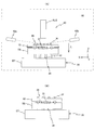
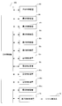
- FIG. 1 is a plan view schematically showing an overall configuration of an exposure system according to an embodiment. It is a figure which shows schematically the load lock chamber with which a vacuum chamber is provided with the exposure unit accommodated in the exposure chamber inside the vacuum chamber. It is a figure which shows the structure of the electron beam exposure apparatus with which the exposure system of FIG. 1 is provided. It is a perspective view which shows the structure of the exposure unit with which an electron beam exposure apparatus is provided. It is a figure which shows a part of electron beam irradiation apparatus with the coarse / fine movement stage with which the wafer shuttle was mounted
- FIG. 7 is a perspective view showing the coarse / fine movement stage of FIG. 6 with the wafer shuttle removed from the fine movement stage. It is a figure which expands and shows the fine movement stage mounted on the surface plate. It is a figure which shows the state which removed the fine movement stage and the magnetic-shielding member from the coarse / fine movement stage shown by FIG.
- FIG. 2 is a diagram for explaining a configuration of a shuttle 10.
- FIG. 11A is a plan view showing the vacuum suction pad
- FIG. 11B is a cross-sectional view taken along the line BB of FIG. 11A.
- FIGS. 12A and 12B are views (No. 1 and No. 2) for explaining the configuration of the first measurement system.
- FIG. 13A is a diagram for explaining the configuration of each part in the measurement chamber
- FIG. 13B is a diagram for explaining the movable range in the vertical direction of the measurement table in FIG. 13A. is there.
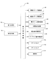
- It is a block diagram which shows the structure of the control system of an exposure system.
- It is a block diagram which shows the input / output relationship of the measurement control apparatus which comprises the control system of FIG.
- It is a block diagram which shows the input / output relationship of the exposure control apparatus which comprises the control system of FIG.
- It is a flowchart for demonstrating an example of the preparatory work performed in a measurement chamber.
- 18A and 18B are diagrams for explaining the operation of mounting the shuttle on the measurement table, and FIGS.
- FIG. 18C and 18D are vacuum suctions of the wafer before exposure to the shuttle.
- FIG. 18E is a diagram for explaining the operation to be performed, and shows a state where the shuttle holding the wafer before exposure is released from the measurement table after releasing the kinematic coupling.
- FIG. 19A is a diagram for explaining the configuration of the load-side shuttle placement unit of the measurement room shuttle delivery unit, and a diagram for explaining the operation of loading the shuttle into the load-side shuttle placement unit
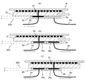
- FIG. (B) is a shuttle from the vacuum suction pad 26 1 view used to explain a delivery of the shuttle 10 to the vacuum suction pad 26 2, to FIG. 19 (C), the vacuum suction pad 26 2 from the vacuum suction pad 26 1 It is a figure which shows the state which 10 delivery completed.
- the vacuum suction state of the wafer W 1 by the shuttle 10 via the vacuum suction pad 26 1, a diagram for explaining the benefits of switching to the vacuum suction state of the wafer W 1 by the shuttle 10 via the vacuum suction pad 26 2 is there.
- 22 (A) to 22 (E) are diagrams (Nos. 1 to 5) for explaining the flow of operations from when the shuttle is carried into the load lock chamber until the shuttle is carried into the exposure chamber. is there.
- FIG. 23 (A) is, explaining a state where the electrostatic adsorption of the wafer W 1 is started by the chuck member with the start of the evacuation of the load lock chamber figures for
- FIG. 23 (E) are diagrams showing a state where the vacuum suction by the vacuum suction pad 26 3 is released naturally.
- 24A to 24D are diagrams for explaining the flow of operations from when a shuttle holding an exposed wafer is carried into the load lock chamber until it is carried out of the load lock chamber. Part 1 to Part 4). It is a figure which shows the structure of the holding
- FIG. 1 schematically shows an overall configuration of an exposure system 1000 according to an embodiment in a plan view.
- the exposure system 1000 includes 11 chambers 80 1 to 80 11 installed on a floor F of a clean room, and a shuttle transfer system 70 that transfers a wafer shuttle described later along a path R indicated by an arrow in FIG. (Only the conveyance path is shown in FIG. 1, see FIGS. 14, 22A, etc.), and a control system and the like are provided.
- a control system and the like are provided.
- two directions orthogonal to each other in a plane parallel to the floor surface F will be described as an X-axis direction and a Y-axis direction
- a direction orthogonal to the floor surface F will be described as a Z-axis direction.
- the eleven chambers 80 1 to 80 11 are composed of five chambers 80 1 to 80 5 and six chambers 80 6 to 80 11 which are arranged on the floor surface F so as to face each other at a predetermined interval in the Y-axis direction. It is divided into two columns.
- the chambers 80 1 to 80 5 are arranged adjacent to each other in the X axis direction on the floor surface F, and the chambers 80 6 to 80 11 are arranged adjacent to each other in the X axis direction on the floor surface F. Has been.
- the chamber 80 1 and the chamber 80 6 face each other
- the chamber 80 and 2 and the chamber 80 7 are opposed to each other
- the chamber 80 5 and the chamber 80 10 face each other.
- the chamber 80 11 is arranged adjacent to the + X side of the chamber 80 10.
- resist coating and developing apparatus (coater developer (hereinafter, abbreviated as C / D)) is disposed.
- Ten chambers 80 i (i 1 to 10), that is, the internal spaces of the chambers 80 1 to 80 10, respectively, are exposure chambers (exposure cells) 81 i (not shown in FIG. 1) in which the wafer is exposed by an electron beam. FIG. 3).
- the exposure chamber 81 i is maintained in a high vacuum state. That is, as the ten chambers 80 i in which the exposure chamber 81 i is formed, a vacuum chamber having a sufficient resistance that is not crushed or deformed by the action of atmospheric pressure is used. Yes.
- the chambers 80 1 to 80 10 are also referred to as vacuum chambers 80 1 to 80 10 or vacuum chambers 80 i .
- the remaining chambers 80 11 are connected in-line to the C / D (not shown).
- the interior space of the chamber 80 11, the wafer predetermined measurement with respect to (C / D wafer electron beam resist is applied by), and unloading of the load and exposed wafer of the wafer before exposure to wafer shuttle to be described later is the target A measurement chamber (measurement cell) 60 (not shown in FIG. 1 and the like, see FIG. 13A) is loaded.
- the internal space of the chamber 80 11 has extremely measuring chamber 60 as described above, there is no need to vacuum atmosphere as the interior space of the vacuum chamber 80 1 to 80 10. Therefore, as the chamber 80 11, it is possible to use a weak chamber strength than the vacuum chamber. Further, by controlling the pressure of the inner space of the inner space and C / D of the chamber 80 11 to be higher than pressure of the clean room, a gas in a clean room (air) entering the chamber 80 11 and the C / D Can be suppressed.
- Yes. 2 shows the same orientation as the vacuum chambers 300 1 to 300 5 , but the vacuum chambers 300 6 to 300 10 are symmetrical to those shown in FIG. It has a configuration.
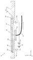
- each load lock chamber 110 i includes a main body portion 110 a in which a load lock chamber to be described later is formed, a front side (atmosphere side) and a back side (vacuum side) of the main body portion 110 a.
- a pair of gate portions 110b and 110c fixed to each other.
- the pair of gate portions 110b and 110c is provided with a gate valve that includes a shutter that opens and closes an opening formed on the front side and the back side of the main body portion 110a and a drive mechanism that slides the shutter up and down.
- a gate valve that includes a shutter that opens and closes an opening formed on the front side and the back side of the main body portion 110a and a drive mechanism that slides the shutter up and down.
- the same reference numerals as those of the gate portion are used to denote the gate valves 110b and 110c. Opening and closing of the gate valves 110b and 110c (that is, opening and closing of the shutter by the driving mechanism) is controlled by the exposure control device 50 i (see FIGS. 14 and 16). Note that the internal configuration of the load lock chamber will be described later when the wafer loading into the load lock chamber is described later.
- the load lock chamber 110 i is connected to a vacuum pipe connected to a vacuum source such as a vacuum pump via an on-off valve 114 (see FIG. 16). Is evacuated as necessary.
- the opening / closing of the on-off valve 114 is also controlled by the exposure control device 50 i .
- the load lock chamber 110 i may be separately provided vacuum pump.
- an exposure unit 82 is accommodated in the exposure chamber 81 i partitioned by the vacuum chamber 80 i . Further, in the exposure chamber 81 i , for example, an exposure chamber transfer system 130 (not shown in FIG. 2, refer to FIG. 16) composed of a horizontal articulated robot is accommodated. Although not shown, a shuttle stocker having a plurality of storage shelves is also installed in the exposure chamber 81 i .
- FIG. 3 shows a configuration of the exposure unit 82 housed in the exposure chamber (exposure cell) 81 i
- FIG. 4 shows a perspective view of the exposure unit 82.
- an electron beam exposure apparatus 100 i (see FIG. 3) is configured including a vacuum chamber 80 i having a load lock chamber 110 i , an exposure unit 82 inside the exposure chamber 81 i , and the like. .
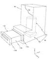
- the exposure unit 82 includes a stage device 83 and an electron beam irradiation device 92, as shown in FIGS.
- the electron beam irradiation device 92 includes a cylindrical barrel 93 shown in FIG. 4 and an electron beam optical system inside the barrel 93.
- the stage device 83 includes a coarse / fine movement stage 85 on which a wafer shuttle 10 that holds and moves the wafer W (see FIG. 3) is detachably mounted.
- the electron beam irradiation device 92 includes the coarse / fine movement stage 85. The wafer W held on the wafer shuttle 10 mounted on the wafer W is irradiated with an electron beam for exposure.
- the wafer shuttle 10 is a holding member (or table) for holding the wafer, which will be described in detail later.
- the wafer shuttle 10 is transported in a state where the holding member holds the wafer, and the holding member is used for the measurement chamber described above. Starting from 60 (see FIG. 13A), the wafer shuttles to and from the exposure chamber 81 i repeatedly, so it is called a wafer shuttle.
- the stage device 83 includes a surface plate 84 and a coarse / fine movement stage 85 that moves on the surface plate 84.
- the stage device 83 includes a drive system that moves the coarse / fine movement stage 85 and a position measurement system that measures positional information of the coarse / fine movement stage. Details of the configuration of the stage device 83 will be described later.
- the lens barrel 93 of the electron beam irradiation device 92 is lowered by a metrology frame 94 made of an annular plate member having three convex portions formed at intervals of a central angle of 120 degrees on the outer peripheral portion. It is supported from. More specifically, the lowermost end portion of the lens barrel 93 is a small-diameter portion whose diameter is smaller than the portion above it, and the boundary portion between the small-diameter portion and the portion above it is a stepped portion. Yes.
- the lens barrel 93 is moved from below by the metrology frame 94. It is supported.
- the metrology frame 94 has three suspension support mechanisms 95a, 95b, and 95c (flexible structure connecting members) each having a lower end connected to each of the three convex portions described above.
- the top plate of the vacuum chamber 80 i partitioning the exposure chamber 81 i is supported in a suspended state from (ceiling wall) (see FIG. 3). That is, in this way, the electron beam irradiation device 92 is supported by being suspended from the vacuum chamber 80 i at three points.
- the three suspension support mechanisms 95a, 95b, and 95c are, as representatively shown for the suspension support mechanism 95a in FIG. (Vibration proof part) It has the wire 97 which consists of steel materials which each one end was connected to the lower end of 96, and the other end was connected to the metrology frame 94.
- the anti-vibration pad 96 is fixed to the top plate of the vacuum chamber 80 i and includes an air damper or a coil spring, respectively.
- the vibration isolation performance in the direction perpendicular to the optical axis (the floor transmitted to the vacuum chamber 80 i from the outside)
- the length of the three suspension support mechanisms 95a, 95b, and 95c (the length of the wire 97) is sufficiently long so that the vibration (such as vibration) can be sufficiently increased. It is set. Further, a positioning device 98 (not shown in FIGS. 3 and 4; see FIG. 16) is provided to maintain the relative position between the electron beam irradiation device 92 and the vacuum chamber 80 i in a predetermined state.
- the positioning device 98 can be configured to include a 6-axis acceleration sensor and a 6-axis actuator, as disclosed in, for example, International Publication No. 2007/077920.
- the positioning device 98 is controlled by the exposure control device 50 i (see FIG. 16).
- the relative positions of the electron beam irradiation device 92 in the X-axis direction, the Y-axis direction, and the Z-axis direction with respect to the vacuum chamber 80 i and the relative rotation angles around the X-axis, Y-axis, and Z-axis are constant ( (Predetermined state).
- FIG. 5 shows a part of the electron beam irradiation apparatus 92 together with the coarse / fine movement stage 85 on which the wafer shuttle 10 is mounted.
- the electron beam irradiation device 92 includes a lens barrel 93 and m (m is 100, for example) optical system columns 20 arranged in the lens barrel 93 in a predetermined positional relationship (for example, in an array in the XY plane).
- An electron beam optical system configured is provided.
- Each optical system column 20 includes a multi-beam optical system that can irradiate n beams (n is, for example, 4000) that can be individually turned on / off and can be deflected.
- the multi-beam optical system for example, an optical system having the same configuration as the optical system disclosed in Japanese Patent Application Laid-Open No. 2011-258842, International Publication No. 2007/017255, or the like can be used.
- the 100 optical system columns 20 correspond to, for example, approximately 100 shot areas formed on a 300 mm wafer (or formed from a shot map according to a shot map) at a ratio of about 1: 1.
- each of the 100 optical system columns 20 has a rectangular shape (for example, 100 ⁇ m ⁇ 100 ⁇ m ⁇ 20 nm). 20 shots) on the wafer, and turning on / off while deflecting the circular spots of the multiple electron beams while scanning the wafer with respect to the exposure area. It is exposed to form a pattern. Therefore, in the case of a 300 mm wafer, it is sufficient that the movement stroke of the wafer at the time of exposure is several tens of mm, for example, 50 mm even with some margin.
- Each optical system column includes a backscattered electron detection system (not shown) that detects backscattered electrons as in a normal electron beam optical system.
- the electron beam irradiation device 92 is controlled by the exposure control device 50 i (see FIG. 16).
- the size of the wafer is arbitrary, and the wafer may have a diameter of 200 mm or 450 mm, for example.
- the number of optical columns may be increased or decreased according to the size of the wafer.
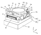
- FIG. 6 shows a perspective view of a state in which a wafer shuttle (hereinafter abbreviated as shuttle) 10 is mounted on the coarse / fine movement stage 85 of the stage device 83.
- FIG. 7 is a perspective view of the coarse / fine movement stage 85 shown in FIG. 6 in a state in which the shuttle 10 is detached (removed).
- the surface plate 84 provided in the stage device 83 is actually installed on the bottom wall of the vacuum chamber 80 i that partitions the exposure chamber 81 i .
- the coarse / fine movement stage 85 includes a coarse movement stage 85a and a fine movement stage 85b.
- the coarse movement stage 85a is arranged at a predetermined interval in the Y-axis direction, includes a pair of quadrangular columnar portions extending in the X-axis direction, and can move on the surface plate 84 with a predetermined stroke, for example, 50 mm, in the X-axis direction. It is.
- the fine movement stage 85b can move with respect to the coarse movement stage 85a in the Y-axis direction with a predetermined stroke, for example, 50 mm, and the remaining five degrees of freedom, that is, the X-axis direction, the Z-axis direction, and the rotation directions around the X-axis ( It is movable in a shorter stroke than the Y-axis direction in the ⁇ x direction), the rotation direction around the Y axis ( ⁇ y direction), and the rotation direction around the Z axis ( ⁇ z direction).
- the pair of square columnar portions of the coarse movement stage 85a are actually connected by a connection member (not shown) in a state that does not prevent the movement of the fine movement stage 85b in the Y-axis direction. It is integrated.
- the coarse movement stage 85a is moved by a coarse movement stage drive system 86 (see FIG. 16) with a predetermined stroke (for example, 50 mm) in the X axis direction (see the long arrow in the X axis direction in FIG. 9).
- the coarse movement stage drive system 86 is constituted by a uniaxial drive mechanism that does not cause magnetic flux leakage in this embodiment, for example, a feed screw mechanism using a ball screw.
- the coarse movement stage drive system 86 is arranged between one square columnar portion and the surface plate 84 of the pair of square columnar portions of the coarse movement stage 85a.
- a screw shaft is attached to the surface plate 84, and a ball (nut) is attached to one square columnar portion.
- bowl to the surface plate 84 and attaches a screw shaft to one square pillar-shaped part may be sufficient.
- the other quadrangular columnar portion is configured to move along a guide surface (not shown) provided on the surface plate 84.
- the screw shaft of the ball screw is rotated by a stepping motor.
- Coarse movement stage drive system 86 is controlled by the exposure control unit 50 i (see FIG. 16).
- fine movement stage 85 b is made of a member having an XZ cross-sectional rectangular frame shape penetrating in the Y-axis direction, and is placed on XY plane on surface plate 84 by weight canceling device 87. It is supported movably. A plurality of reinforcing ribs are provided on the outer surface of the side wall of fine movement stage 85b.
- a yoke 88a having a rectangular frame shape in the XZ section and extending in the Y-axis direction, and a pair of magnet units 88b fixed to the upper and lower opposing surfaces of yoke 88a.
- 88a and a pair of magnet units 88b constitute a mover 88 of a motor that moves fine movement stage 85b.
- FIG. 9 shows a state in which a magnetic shield member (to be described later) indicated by fine movement stage 85b and reference numeral 91 is removed from FIG.
- a stator 89 made of a coil unit is installed between a pair of square column portions of the coarse movement stage 85 a.
- the movable element 88 can be moved with respect to the stator 89 by a predetermined stroke, for example, 50 mm in the Y-axis direction, as indicated by arrows in each direction in FIG.
- a closed magnetic field type and moving magnet type motor 90 that can be moved minutely in the X axis direction, the Z axis direction, the ⁇ x direction, the ⁇ y direction, and the ⁇ z direction is configured.
- a fine movement stage drive system is configured in which the fine movement stage 85b is moved in the direction of six degrees of freedom by the motor 90.
- the fine movement stage drive system is referred to as a fine movement stage drive system 90 using the same reference numerals as those of the motor.
- Fine movement stage drive system 90 is controlled by exposure control device 50 i (see FIG. 16).
- the XZ cross section is reversed while covering the upper surface of the motor 90 and both side surfaces in the X-axis direction.
- a U-shaped magnetic shield member 91 is installed.
- the magnetic shield member 91 is inserted into the hollow portion of the fine movement stage 85b, and the lower surface of both end portions in the longitudinal direction (Y-axis direction) is the upper surface of the pair of quadrangular column portions of the coarse movement stage 85a. It is fixed to. Further, of the side surfaces of the magnetic shield member 91, the surfaces other than the lower surfaces of the both end portions are opposed to the bottom wall surface (lower surface) of the inner wall surface of the fine movement stage 85b without contact.
- the magnetic shield member 91 covers the upper surface and the side surface of the motor 90 over the entire length of the moving stroke of the mover 88 and is fixed to the coarse movement stage 85a, the fine movement stage 85b and the coarse movement stage 85a. Leakage of magnetic flux upward (on the electron beam optical system side) can be prevented almost certainly over the entire moving range.
- the weight canceling device 87 includes a metal bellows type air spring (hereinafter abbreviated as an air spring) 87a whose upper end is connected to the lower surface of the fine movement stage 85b, and a lower end of the air spring 87a. And a base slider 87b made of a connected flat plate member.
- the base slider 87b is provided with a bearing portion that blows air inside the air spring 87a onto the upper surface of the surface plate 84, and a static pressure between the bearing surface of the pressurized air ejected from the bearing portion and the upper surface of the surface plate 84.
- the weight of the weight canceling device 87, the fine movement stage 85b, and the mover 88 (including the shuttle 10 when the shuttle 10 is mounted on the coarse / fine movement stage 85) is supported by (pressure in the gap). Note that compressed air is supplied to the air spring 87a via a pipe (not shown) connected to the fine movement stage 85b.
- the base slider 87b is supported in a non-contact manner on the surface plate 84 via a kind of differential exhaust type aerostatic bearing, and air blown from the bearing portion toward the surface plate 84 is surrounded by (exposure chamber). To prevent leakage.
- three triangular pyramid groove members 12 are provided on the upper surface of fine movement stage 85b.
- the triangular pyramidal groove member 12 is provided at the positions of three apexes of a regular triangle in plan view.
- the triangular pyramid groove member 12 can be engaged with a sphere or hemisphere, which will be described later, provided on the shuttle 10 and constitutes a kinematic coupling with the sphere or hemisphere.
- FIG. 7 shows a triangular pyramid groove member 12 such as a petal composed of three plate members.
- the triangular pyramid groove member 12 is a triangular pyramid that makes point contact with a sphere or a hemisphere, respectively. Since it has the same role as the groove, it is called a triangular pyramid groove member. Therefore, a single member in which a triangular pyramid groove is formed may be used instead of the triangular pyramid groove member 12.
- three spheres or hemispheres (balls in the present embodiment) 14 are provided on the shuttle 10 as shown in FIG.
- the shuttle 10 is formed in a hexagonal shape in which each vertex of an equilateral triangle is cut off in plan view. More specifically, the shuttle 10 has notches 10a, 10b, and 10c formed at the center of each of the three oblique sides in plan view, and covers the notches 10a, 10b, and 10c from the outside.
- the leaf springs 16 are respectively attached. Balls 14 are fixed to the center of each leaf spring 16 in the longitudinal direction.
- each ball 14 In a state before being engaged with the triangular pyramid groove member 12, each ball 14, when receiving an external force, has a radial direction centered on the center of the shuttle 10 (substantially coincident with the center of the wafer W shown in FIG. 6). Only move to a minute.
- the shuttle 10 After moving the shuttle 10 to a position where the three balls 14 substantially oppose the three triangular pyramidal groove members 12 above the fine movement stage 85b, respectively, the shuttle 10 is moved down so that each of the three balls 14 becomes The three triangular pyramid groove members 12 are individually engaged, and the shuttle 10 is mounted on the fine movement stage 85b. Even when the position of the shuttle 10 with respect to the fine movement stage 85b is deviated from the desired position at the time of mounting, when the ball 14 engages with the triangular pyramid groove member 12, the external force is received from the triangular pyramid groove member 12, and the aforementioned As a result of the radial movement, the three balls 14 always engage with the corresponding triangular pyramidal groove members 12 in the same state.
- the shuttle 10 can be easily detached (detached) from the fine movement stage 85b simply by moving the shuttle 10 upward and releasing the engagement between the ball 14 and the triangular pyramid groove member 12. That is, in this embodiment, a kinematic coupling is constituted by the set of three balls 14 and the triangular pyramid groove member 12, and the kinematic coupling always keeps the mounting state of the shuttle 10 to the fine movement stage 85b substantially the same. It can be set to the state. Therefore, no matter how many times it is removed, the shuttle 10 and the fine movement of the shuttle 10 can be moved by simply mounting the shuttle 10 on the fine movement stage 85b via the kinematic coupling (the set of three pairs of balls 14 and the triangular pyramid groove member 12). A certain positional relationship with the stage 85b can be reproduced.
- a circular concave portion 10d having a diameter slightly larger than that of the wafer W is formed at the center, and a chuck member described later is provided in the concave portion 10d.
- the wafer W is sucked and held.
- the surface of the wafer W is substantially flush with the upper surface of the shuttle 10.
- the shuttle 10 includes a shuttle body 11 made of the plate member having a hexagonal shape in plan view described above, and has a predetermined depth in a circular shape in plan view on the upper surface of the shuttle body 11.
- a recessed portion 10d is formed.
- the shuttle 10 includes a shuttle main body 11 and a chuck member 22 disposed in the recess 10d.
- the chuck member 22 includes a base portion 22a having a circular shape in plan view having a diameter substantially the same as that of the wafer W, an annular rim portion 22b provided on the base portion 22a, and an inner portion of the rim portion 22b.
- a plurality of pin portions 22c provided at predetermined intervals on the upper surface of the base portion 22a.
- the rim portion 22 b has an outer diameter that is somewhat smaller than the diameter of the wafer W.
- the upper surfaces of the many pin portions 22c are located on substantially the same plane as the upper surface of the rim portion 22b.
- a wafer mounting portion is constituted by a large number of pin portions 22c and rim portions 22b.
- a space hereinafter, referred to as “closed” between the back surface of the wafer W, the inner peripheral surface of the rim portion 22b, and the upper surface of the base portion 22a (hereinafter referred to as the outside). (Referred to as a closed space).
- the upper surface (wafer mounting surface) of the wafer mounting portion is positioned lower than the upper surface of the shuttle main body 11 by substantially the same dimension as the thickness of the wafer W.
- the chuck member 22 is integrally formed of ceramics, for example. Although not shown, for example, a plurality of plate-like electrodes are embedded in the lower surface of the base portion 22a so as to form the same surface as a whole together with other portions.
- the chuck member 22 is disposed in the recess 10d in such a state that a plurality of flat electrodes embedded in the lower surface and the lower surface of the surrounding base portion 22a are in close contact with the inner bottom surface of the recess 10d of the shuttle body 11.
- the shuttle main body 11 has at least a portion including the concave portion 10d formed of a dielectric, for example, the same kind (or different kind) of ceramics as the chuck member 22.
- the base wall portion 22a of the chuck member 22 and the bottom wall portion of the recess 10d of the shuttle body 11 have a predetermined shape in plan view that communicates the upper surface of the base portion 22a and the lower surface of the shuttle body 11 at the center position of the rim portion 22b.
- a circular air passage 24 is formed.
- the bottom wall portion of the recess 10d of the shuttle main body 11 and the chuck member 22 have a plurality of circular openings (not shown) penetrating both above and below, and a predetermined positional relationship (a plurality of pins 32 (the measurement stage device 30 described later). (Refer to FIG. 13A)).
- the shuttle main body 11 and the chuck member 22 are separate members.
- the present invention is not limited to this, and a shuttle having portions corresponding to the shuttle main body 11 and the chuck member 22 is made of dielectric such as ceramics.
- the plurality of flat plate electrodes may be embedded in the shuttle.
- One end of either of the two switches SW1 and SW2 shown in FIG. 10 is connected to each of the plurality of plate-like electrodes described above.
- the other end of the switch SW1 is connected to the negative electrode (potential ⁇ Vcc) of a DC voltage source whose positive electrode is set to the ground potential, and the other end of the switch SW2 is connected to the positive electrode (DC voltage source) whose negative electrode is set to the ground potential.
- Potential + Vcc is connected.
- the switches SW1 and SW2 are turned on / off simultaneously.
- the shuttle 10 is provided with a shuttle-side contact
- the shuttle 10 is provided with a shuttle external contact on the fine movement stage or the measurement stage mounted via the kinematic mount
- the shuttle 10 is provided with the fine movement stage via the kinematic mount.
- the switches SW1 and SW2 can be realized by adopting a configuration in which the shuttle-side contact and the shuttle external contact are in contact with each other by mounting the switch 85b or the like.
- a battery as a DC voltage source is built in the shuttle 10 and switches SW1 and SW2 are provided.
- a voltage is applied to the plurality of plate-like electrodes of the chuck member 22 by the respective DC voltage power supplies.
- positive and negative potentials are generated inside the chuck member 22 and an electrostatic force is generated between the dielectric-polarized wafer W (adsorbed member).
- the electrostatic force causes the chuck member 22 upper surface (wafer mounting).
- the wafer can be adsorbed on the mounting surface. That is, the chuck member 22 can function as an electrostatic chuck.
- the electrostatic chuck uses an insulating material as the dielectric layer, and uses a Coulomb force type that attracts the target using the electric charge induced between the electrode and the target, and the dielectric layer is slightly conductive.
- a Johnson-Labeck force type that adsorbs an object using a Johnson-Labeck force generated by charge transfer in the dielectric layer, and either one may be used.
- TiAlN titanium nitride aluminum
- a material with a high friction coefficient such as may be coated.
- a ground intake vacuum suction pad (hereinafter abbreviated as a vacuum suction pad) 26 is provided on the shuttle 10, as shown in FIG.
- a vacuum suction pad By attaching and vacuuming (exhausting) the vacuum piping 25 and the air passage 24 for the wafer chuck, the inside of the above-mentioned closed space is also vacuum-sucked, and the wafer W can be vacuum-sucked on the upper surface of the chuck member 22.
- the shuttle 10 having the chuck member 22 constitutes a main body member including an electrostatic chuck, and the holding device 18 includes the shuttle 10 and the vacuum suction pad 26.
- the vacuum suction pad 26 may be called a suction force generation member or a flow path member.
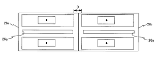
- FIG. 11 (A) shows a plan view of the vacuum suction pad 26.
- FIG. 11B shows an enlarged view of a cross section taken along line BB of FIG. 11A together with an object (here, shuttle 10) to which the vacuum suction pad 26 is attached.
- the shuttle 10 is shown in a simplified manner in FIG. Note that the coordinate system (X, Y, Z) in FIGS. 11A and 11B corresponds to FIG.
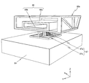
- the vacuum suction pad 26 is composed of a plate-like member having a predetermined thickness and having a rectangular shape in plan view, with tapered portions formed on both side surfaces (surfaces on both sides in the X-axis direction in FIG. 11B).
- the taper portion is formed to facilitate positioning to a desired position when the vacuum suction pad 26 is placed on a measurement table, a load side placement portion, and a shuttle delivery portion in the load lock chamber, which will be described later.
- the vacuum suction pad 26 has a predetermined width in the center in the X-axis direction and a predetermined length in the Y-axis direction on the upper surface (+ Z side surface).
- a vacuum supply groove 26a having a predetermined depth is formed.
- the vacuum supply groove 26a is formed over substantially the entire length of the vacuum suction pad 26 in the Y-axis direction (excluding part of both ends).
- a pair of vacuum preload type air bearing portions 26b (see FIG. 11A) is provided with a vacuum supply groove 26a sandwiched in the X-axis direction.
- the vacuum preload type air bearing portion 26 b includes a vacuum preload portion 27 formed of a rectangular recess in plan view, and an air bearing portion 28 provided at the center of the vacuum preload portion 27.
- the air bearing portion 28 includes a bearing portion 28a formed of a rectangular convex portion provided at the center of the vacuum preload portion 27, and a nozzle portion 28b formed at the center of the bearing portion 28a.
- air passages 29a, 29b extending in the vertical direction (Z-axis direction) for communicating the insides of the vacuum supply groove 26a, the vacuum preload portion 27, and the nozzle portion 28b with the outside of the vacuum suction pad 26 29c is formed.
- a vacuum pump (not shown) is connected to the air passage 29a via the wafer chuck vacuum pipe 25 (not shown in FIG. 11B, see FIG. 10) and an open / close valve (not shown). Further, a vacuum pump (not shown) is connected to each vent passage 29b via a vacuum pipe (not shown) and an opening / closing valve.
- the vacuum pumps connected to the air passage 29a and each air passage 29b may be the same vacuum pump or may be separate vacuum pumps.
- each of the pair of vacuum preloading portions 27 is provided with two ventilation paths 29b.
- each vacuum preloading section 27 has one ventilation path 29b. It is enough if one is provided.
- the ventilation paths 29a and 29b are also referred to as an exhaust path 29a and an exhaust path 29b.
- a supply source of pressurized air such as an air tank is connected to each air passage 29c through a pipe and an opening / closing valve (not shown).
- the air passage 29c is also referred to as an air supply passage 29c.
- pressurized air is ejected from the nozzle portions 28b to the lower surface of the shuttle 10 via the air supply passages 29c, and the interior of the vacuum preloading portion 27 is passed through the exhaust passages 29b.
- the air in the gap between the bearing portion 28a and the shuttle 10 is vacuum-sucked (exhausted to the outside) by a vacuum pump, so that the vacuum suction pad 26 is passed through a gap (clearance, gap) of about several ⁇ , for example. , It can be adsorbed to the lower surface of the shuttle 10 in a non-contact state.
- the vacuum suction pad 26 can be adsorbed (fixed) in contact with the lower surface of the shuttle 10. If the vacuum supply groove 26a faces the air passage 24 of the shuttle 10 in both the former non-contact state and the latter contact state, the air passage 24, the vacuum supply Via the groove 26a and the exhaust passage 29a, the inside of the closed space can be communicated with the inside of the vacuum piping 25 for the wafer chuck, and the open / close valve is opened so that the air inside the vacuum piping 25 is vacuum pumped.
- the exhaust path 29 a is a flow path for vacuum-sucking the wafer W placed on the shuttle 10 through the ventilation path 24.
- the vacuum suction state of the wafer W can be maintained as long as the vacuum supply groove 26a of the vacuum suction pad 26 faces the air passage 24 of the shuttle 10. Therefore, the vacuum suction pad 26 and the shuttle 10 are relatively moved in the Y-axis direction while maintaining the non-contact suction state of the vacuum suction pad 26 to the lower surface of the shuttle 10 and the vacuum suction state of the wafer W to the chuck member 22. Can be moved a predetermined distance.
- first suction state is also referred to as “non-contact adsorption state with respect to an object (for example, shuttle)”
- second suction state is also referred to as “contact adsorption state with respect to an object”.
- a state in which the ejection of the pressurized air from the nozzle portion 28b of each air bearing portion 28 is on and the vacuum preload by the vacuum preloading portion 27 is off is called a “spout state”, and this “spout state” is “ It is also called “air floating state with respect to the object”.
- the state in which the pressurized air ejection is off includes a state in which the pressurized air is ejected to such an extent that the vacuum suction pad 26 can be adsorbed to the lower surface of the shuttle 10 in a contact state.
- This position measurement system includes the first measurement system 52 that measures the position information of the shuttle 10 and the position information of the fine movement stage 85b in a state where the shuttle 10 is mounted on the fine movement stage 85b via the kinematic coupling described above. And a second measurement system 54 that directly measures (see FIG. 16).
- grating plates 72a, 72b, and 72c are provided in the vicinity of the three sides of the shuttle 10 excluding the aforementioned three oblique sides.
- Each of the grating plates 72a, 72b, and 72c has a radial direction centered on the center of the shuttle 10 (in the present embodiment, coincident with the center of the circular recess 10d) and a direction perpendicular thereto as a periodic direction.
- Two-dimensional lattices are formed.
- the grating plate 72a is formed with a two-dimensional lattice having a periodic direction in the Y-axis direction and the X-axis direction.
- the grating plate 72b is formed with a two-dimensional grating having a direction that is ⁇ 120 degrees with respect to the Y axis with respect to the center of the shuttle 10 (hereinafter referred to as ⁇ direction) and a direction perpendicular thereto as a periodic direction.
- the grating plate 72c is formed with a two-dimensional grating having a direction that forms +120 degrees with respect to the Y axis with respect to the center of the shuttle 10 (hereinafter referred to as ⁇ direction) and a direction perpendicular thereto as a periodic direction.
- a reflection type diffraction grating having a pitch of, for example, 1 ⁇ m is used in each periodic direction.
- each of the three head portions 74a, 74b, and 74c is provided with a four-axis encoder head having measurement axes indicated by four arrows in FIG. 12B.
- the head portion 74a includes a first head housed in the same housing and having a measurement direction in the X-axis direction and the Z-axis direction, and a measurement direction in the Y-axis direction and the Z-axis direction. And a second head.
- the first head (more precisely, the irradiation point on the grating plate 72a of the measurement beam emitted by the first head) and the second head (more precisely, the irradiation of the measurement beam emitted by the second head on the grating plate 72a).
- the first head (more precisely, the irradiation point on the grating plate 72a of the measurement beam emitted by the first head) and the second head (more precisely, the irradiation of the measurement beam emitted by the second head on the grating plate 72a).
- the first head and the second head of the head portion 74a are each a biaxial linear encoder that measures position information of the shuttle 10 in the X-axis direction and the Z-axis direction, and the Y-axis direction and the Z-axis direction using the grating plate 72a.
- a two-axis linear encoder that measures the position information is configured.
- the remaining head portions 74b and 74c are configured in the same manner as the head portion 74a including the first head and the second head, although the directions with respect to the respective metrology frames 94 are different (measurement directions in the XY plane are different). ing.
- the first head and the second head of the head part 74b each use a grating plate 72b to measure the position information in the direction orthogonal to the ⁇ direction of the shuttle 10 in the XY plane and the position information in the Z-axis direction, and A two-axis linear encoder that measures position information in the ⁇ direction and the Z-axis direction is configured.
- the first head and the second head of the head portion 74c each use a grating plate 72c, and a biaxial linear encoder that measures position information in a direction orthogonal to the ⁇ direction of the shuttle 10 in the XY plane and in the Z axis direction, and A two-axis linear encoder that measures position information in the ⁇ direction and the Z-axis direction is configured.
- the encoder head of the structure similar to the displacement measurement sensor head disclosed by the US Patent 7,561,280, for example is used. Can be used.
- An encoder system is constituted by the three head portions 74a, 74b, and 74c that measure the position information of the shuttle 10 using the above-described three sets, that is, a total of six biaxial encoders, that is, three grating plates 72a, 72b, and 72c, respectively.
- the first measurement system 52 (see FIG. 16) is configured by this encoder system.
- the position information measured by the first measurement system 52 is supplied to the exposure control device 50 i .
- the three head portions 74a, 74b, and 74c each have four measurement degrees of freedom (measurement axes)
- a total of 12 degrees of freedom can be measured. That is, in the three-dimensional space, since the maximum degree of freedom is 6, redundant measurement is actually performed for each of the 6 degrees of freedom directions, and two pieces of position information are obtained.
- the exposure control device 50 i uses the average value of the two pieces of position information for each degree of freedom as the measurement result in each direction based on the position information measured by the first measurement system 52. Thereby, it becomes possible to obtain
- the second measurement system 54 can measure position information in the direction of 6 degrees of freedom of the fine movement stage 85b regardless of whether or not the shuttle 10 is mounted on the fine movement stage 85b.
- the second measurement system 54 irradiates the reflection surface provided on the outer surface of the side wall of the fine movement stage 85b with measurement light, receives the reflected light, and measures the position information of the fine movement stage 85b in the 6-degree-of-freedom direction. It can be configured by a metering system.
- Each interferometer of the interferometer system may be suspended and supported on the metrology frame 94 via a support member (not shown), or may be fixed to the surface plate 84.
- the second measurement system 54 Since the second measurement system 54 is provided in the exposure chamber 81 i (in the vacuum space), there is no possibility of a decrease in measurement accuracy due to air fluctuation.
- the second measurement system 54 mainly sets the position and orientation of the fine movement stage 85b to a desired position when the shuttle 10 is not mounted on the fine movement stage 85b, that is, when the wafer is not exposed. Since it is used to maintain the state, the measurement accuracy may be lower than that of the first measurement system 52.
- Position information measured by the second measurement system 54 is supplied to the exposure control device 50 i (see FIG. 16).
- you may comprise a 2nd measurement system not only by an interferometer system but by an encoder system or the combination of an encoder system and an interferometer system. In the latter case, position information in the direction of three degrees of freedom in the XY plane of 85b of the fine movement stage may be measured by the encoder system, and position information in the remaining three degrees of freedom direction may be measured by the interferometer system.
- Measurement information according to the first measurement system 52 and the second measurement system 54 is sent to an exposure control device 50 i, the exposure control unit 50 i is based on the measurement information of the first measurement system 52 and / or the second measurement system 54 Then, the coarse / fine movement stage 85 is controlled.
- the measurement chamber transfer system 62 includes a measurement chamber first transfer system 62A that transfers the shuttle 10 and a measurement chamber second transfer system 62B that transfers the wafer.
- the measurement chamber first transfer system 62 ⁇ / b> A and the measurement chamber second transfer system 62 ⁇ / b> B are composed of, for example, a horizontal articulated robot that transfers the wafer W or the shuttle 10.
- the vacuum suction pad 26 needs to be transported alone by the first transport system 62A in the measurement chamber. It has the composition of.
- the shuttle 10 is detachably mounted on the measurement table TB through the same kinematic coupling as described above.
- the measurement system 40 performs a predetermined measurement on the wafer W held on the shuttle 10.
- a shuttle stocker (not shown) having a plurality of shelves that can store the shuttle 10 and capable of storing the plurality of shuttles 10 at the same time.
- the shuttle stocker also has a temperature control function of the shuttle 10 accommodated therein.
- the measurement table TB a plurality of circular openings are formed in an arrangement corresponding to the above-described plurality of circular openings formed in the shuttle 10.
- the measurement stage ST is provided with a plurality of pins 32 in an arrangement corresponding to a plurality of circular openings, and the plurality of pins 32 are a plurality of circles of the measurement table TB.
- the measurement table TB is arranged on the measurement stage ST in a state where it is individually inserted into the opening.
- the measurement table TB is moved by a drive system 34 provided on the measurement stage ST, and can be moved up and down (moved in the Z-axis direction) with a predetermined stroke.
- the measurement table TB is such that the upper surface of the shuttle 10 is higher than the upper end surfaces of the plurality of pins 32 by a predetermined distance in a state where the shuttle 10 is mounted via the kinematic coupling (the upper end surfaces of the plurality of pins). 13 does not protrude from the upper surface of the shuttle 10) and the wafer mounting surface (upper surface of the chuck member 22) of the shuttle 10 is lower than the upper end surfaces of the plurality of pins 32 by a predetermined distance (see FIG. 13A).
- the upper end surfaces of the plurality of pins 32 protrude from the wafer mounting surface of the shuttle 10 and can move up and down between the second positions shown in FIG.
- the measurement table TB may be placed on the measurement stage ST, and the plurality of pins 32 may be moved up and down with respect to the measurement table TB.
- a concave portion 31 having a rectangular shape in a plan view is formed at the center.
- the above-described vacuum suction pad 26 can be arranged (stored) in the recess 31 with the upper half exposed. . Further, even when the vacuum suction pad 26 is housed in the recess 31, the depth of the recess 31, the vacuum suction pad so that the shuttle 10 can be mounted on the measurement table TB via the kinematic coupling without any trouble. 26 height dimensions and the like are defined.
- a configuration is adopted in which the piping such as the vacuum piping connected to the vacuum suction pad 26 does not interfere with the mounting of the shuttle 10 on the measurement table TB in a state where the vacuum suction pad 26 is disposed in the recess 31.
- the piping is connected to a vacuum source and a high-pressure air source provided in the first transfer system 62A in the measurement chamber.
- the measurement stage ST is moved (including rotation in the ⁇ z direction) in the XY plane by a measurement stage drive system 36 (see FIG. 15) composed of a planar motor, for example.
- Position information of the measurement stage ST in the XY plane is measured by a measurement stage interferometer 38 (see FIG. 15).
- the vertical position of the measurement table TB is measured by an encoder included in the drive system 34.
- the operation of each part of the measurement stage device 30 is controlled by the measurement control device 64 (see FIG. 15).
- the measurement system 40 includes an alignment detection system ALG, and a surface position detection apparatus AF (see FIG. 15) having an irradiation system 42a and a light receiving system 42b.
- the origin of the two-dimensional orthogonal coordinate system (reference coordinate system) defined by the measurement axis of the measurement stage interferometer 38 coincides with the detection center of the alignment detection system ALG. To do.
- the upper surface of the wafer W held on the shuttle 10 is coated with a sensitive agent (electron beam resist), so that an electron beam is used as detection light of the alignment detection system ALG.
- a detection beam having a wavelength that does not expose the resist is used.
- the alignment detection system ALG for example, a broadband detection light beam that does not sensitize the resist applied to the wafer W is irradiated onto the target mark, and the image of the target mark formed on the light receiving surface by the reflected light from the target mark is not detected.
- An image processing type FIA (Field Image Alignment) system that takes an image of an indicator (an indicator pattern on an indicator plate provided inside) using an imaging device (CCD or the like) and outputs the image pickup signal. Is used.
- the imaging signal from the alignment detection system ALG is supplied to the measurement control device 64 via a signal processing device (not shown) (see FIG. 15).
- the alignment detection system ALG is not limited to the FIA system.
- the target mark is irradiated with coherent detection light, and two diffracted lights generated from the target mark (for example, diffracted light of the same order or in the same direction) are diffracted.
- a diffracted light interference type alignment detection system that detects by diffracting light may be used instead of the FIA system.
- the surface position detector AF has an irradiation system 42a and a light receiving system 42b, and is an oblique incidence type multi-point focal position having the same configuration as disclosed in, for example, US Pat. No. 5,448,332. Consists of a detection system.
- the plurality of detection points of the surface position detection device AF are arranged at predetermined intervals along the X-axis direction on the surface to be detected. In this embodiment, for example, they are arranged in a row matrix of 1 row and M columns (M is the total number of detection points) or 2 rows and N columns (N is 1/2 of the total number of detection points).
- the plurality of detection points are set almost evenly in a region having a length in the X-axis direction that is about the same as the diameter of the wafer W.
- the position information (surface position information) in the Z-axis direction can be measured on almost the entire surface of the wafer W only by scanning the wafer W once in the Y-axis direction.
- the components placed in the measurement chamber 60 described above, that is, the measurement stage device 30, the measurement system 40, the measurement chamber conveyance system 62, and the like, and the measurement control device 64 are held on the shuttle 10.
- a measuring unit 65 that performs pre-measurement on the wafer before exposure is configured (see FIG. 15).
- Vacuum aforementioned shuttle transfer system 70 (see FIG. 14) is moved along a path R shown by the arrows in FIG. 1, the shuttle 10 holding the wafer before exposure, the chamber 80 11 inside measurement chamber 60
- the shuttle 10 is loaded into the load lock chamber 112 i (see FIG. 22A) inside the load lock chamber 110 i provided in each chamber 80 i and holds the exposed wafer from the load lock chamber 112 i to the measurement chamber 60.
- the shuttle transfer system 70 is configured by a horizontal articulated robot that can move along the path R and has, for example, a U-shaped arm portion in plan view.
- the shuttle transport system 70 is configured such that the shuttle 10 can be transported while being supported by the arm portion from below, or the vacuum suction pad 26 can be transported alone.
- the shuttle transport system 70 is controlled by a transport system control device 75 (see FIG. 14) including a microcomputer or the like.
- the shuttle transport system 70 has a configuration capable of transporting the vacuum suction pad 26 alone, and holds piping for connecting the vacuum suction pad 26 and the vacuum source and the high-pressure air source, respectively. .
- FIG. 14 is a block diagram showing the configuration of the control system of the exposure system 1000.
- FIG. 15 is a block diagram showing the input / output relationship of the measurement control device 64 constituting the control system of FIG.
- the measurement control device 64 includes a microcomputer and the like, and controls each unit shown in FIG. 15 provided in the measurement chamber 60.
- the exposure control device 50 i includes a microcomputer or the like, and controls each unit shown in FIG. 16 provided in the exposure chamber 81 i .
- the vacuum suction pad 26 since it is more used, in the following, for identification, the individual vacuum suction pads, vacuum suction pads 26 1, 26 2, etc. 26 3 and denoted.
- the vacuum pipes connected to the vacuum suction pads 26 1 , 26 2 , and 26 3 are denoted as vacuum pipes 25 1 , 25 2 , and 25 3 , respectively.
- a plurality of shuttles 10 are stored in a shuttle stocker (not shown). Further, it is assumed that the wafer before exposure is placed on the substrate transfer unit by the C / D side wafer transfer system connected inline to the measurement chamber 60.
- step S102 the shuttle 10 stored in a shuttle stocker (not shown) is mounted on the measurement table TB. Specifically, the shuttle 10 stored in the shuttle stocker (not shown) is unloaded from the shuttle stocker by the first transfer system 62A in the measurement chamber, and is moved to the wafer exchange position as shown in FIG. It is conveyed above the measurement table TB located at the second position on the measurement stage ST. At this time, the lower surface of the shuttle 10, the vacuum suction pad 26 1 is attracted in contact, and a vacuum supply groove 26a faces the air passage 24 of the shuttle 10. Then, the shuttle 10 moves downward as indicated by a black arrow in FIG. 18A by the first transfer system 62A in the measurement chamber (only a part of the arm is shown in FIG. 18A).
- the vacuum suction pad 26 1 is disposed in the recess 31. Thereafter, the measuring chamber first transport system 62A is retracted from the measurement table TB, in the vicinity of the measuring table TB, keeps some pipes connected to a vacuum suction pad 26 1 waits.
- the wafer before exposure in the substrate transfer unit by the measuring chamber second transport system 62B (for convenience, the wafer W 1) is passed to a plurality of pins 32 of the measuring stage ST .
- the measurement table TB is in a second position, in this state, the wafer W 1 is in a state where the rotational position displacement and displacement between the center positions is adjusted is placed on the plurality of pins 32.
- Figure 18 (C) the wafer W 1 is passed to a plurality of pins 32, the measuring chamber second conveying system 62B is shown the state after the evacuation from the measurement table TB upward.
- next step S106 to hold the wafer W 1 to the shuttle 10. Specifically, as shown in FIG. 18 (D), by moving upward the measurement table TB to the first position, the wafer W 1 on the chuck member 22 the upper surface of the shuttle 10 (wafer mounting surface) Place.
- next step S107 it starts the vacuum suction of the wafer W 1 via the vacuum suction pad 26 1 (vacuum suction).
- vacuum suction pads 26 1 vacuum supply groove 26a which is contacted adsorbed to the lower surface of the shuttle 10, the exhaust passage 29a and the vacuum pipe 25 of the shuttle 10, the base portion 22a and the rim of the chuck member 22
- This is performed by vacuuming (exhausting) the air in the closed space defined by the portion 22b and the wafer W.
- Figure 18 (D) the wafer W 1 is shown a state in which vacuum-sucked to the shuttle 10 via the vacuum suction pad 26 1.
- the wafer W 1 has a predetermined adsorption pressure, that is, an adsorption pressure corresponding to an adsorption pressure when electrostatically attracting the wafer W 1 by the shuttle 10 during exposure of the wafer W 1 to be described later. 22). Since then, while the wafer W 1 is vacuum adsorbed to the shuttle 10 via the vacuum suction pad 26 1, a predetermined suction pressure is maintained.
- next step S108 it performs an outline (rough) position measurement with respect to the shuttle 10 of the wafer W 1. More specifically, first, after the search alignment of the wafer W 1, and measures the positional information of the reference mark provided on the shuttle 10 (not shown), the relative wafer W 1 for the shuttle 10 (reference marks) Find location information.
- search mark located on the periphery portion substantially symmetrical with respect to the center of the wafer W 1 (hereinafter, referred to as search mark) is detected.
- the measurement control device 64 controls the movement of the measurement stage ST by the measurement stage drive system 36 and positions each search mark within the detection region (detection field of view) of the alignment detection system ALG while using the measurement stage interferometer 38. acquires measurement information, a detection signal upon detection of search mark formed on the wafer W 1 by using the alignment detection system ALG, based on the measurement information by the measuring stage interferometer 38, the position information of each search mark Ask for.
- the measurement control device 64 detects the detection result of the alignment detection system ALG output from a signal processing device (not shown) (the detection center (index center) of the alignment detection system ALG obtained from the detection signal) and each search mark. Relative position) and the measurement value of the measurement stage interferometer 38 when each search mark is detected, the position coordinates of the two search marks on the reference coordinate system are obtained.
- the reference coordinate system is an orthogonal coordinate system defined by the measurement axis of the measurement stage interferometer 38.
- the measurement control device 64 obtains the position coordinates on the reference coordinate system of the plurality of reference marks provided on the shuttle 10 in the same procedure as the search mark. Then, based on the position coordinates of the position coordinates and a plurality of reference marks of the two search marks to determine the relative position with respect to the shuttle 10 of the wafer W 1. Accordingly, the approximate position measuring relative the shuttle 10 of the wafer W 1 is completed. Incidentally, the wafer W 1, since in fact loaded on the shuttle 10 in a state where the rotational position deviation and the center position deviation is adjusted, the more central position deviation of the wafer W 1 is negligibly small, the residual rotation error is very Small.
- step S109 performs wafer alignment by the EGA method for determining the sequence of a plurality of shot areas on the wafer W 1. More specifically, the step moves the measuring stage ST in the XY plane, the detection region of the alignment system ALG 3 or more predetermined number sequentially positioning the alignment mark on the wafer W 1 (at least 16 in this case) Then, the predetermined number of alignment marks are sequentially detected by the alignment system ALG. Then, based on the detection result of each alignment mark and the measurement information of the measurement stage interferometer 38 at the time of each detection, the position of each of the predetermined number of alignment marks on the aforementioned reference coordinate system is obtained.
- step S110 flatness measurement of the wafer W 1 (Measurement of surface irregularities) is performed.
- This flatness measurement is performed by capturing measurement information of the surface position detector AF and measurement information of the measurement stage interferometer 38 at a predetermined sampling interval while moving the measurement stage ST in the Y-axis direction.
- the wafer flatness is measured in the electron beam exposure apparatus because a position measurement error (lateral deviation) in the XY plane of the wafer occurs due to the unevenness of the wafer surface. This is because the measurement error needs to be corrected.
- This position measurement error can be easily obtained by calculation based on wafer flatness information (Z position information Z (X, Y) corresponding to XY coordinate position (X, Y) on the wafer coordinate system). . Since the information on the rotational deviation of the wafer is known by the search alignment, the relationship between the wafer coordinate system and the reference coordinate system can be easily obtained.
- step S111 the shuttle 10 holding the wafer W 1 is, by measuring the room first conveyor system 62A, is moved upward, the measurement table TB to release the kinematic coupling (See FIG. 18E). At this time, vacuum suction pads 26 1 remains attached to the shuttle 10 (fixed), vacuum suction of the wafer W 1 via the vacuum suction pad 26 1 (vacuum suction) is continued.
- the shuttle 10 which is held by vacuum suction of the wafer W 1 via the vacuum suction pad 26 1, the internal measurement chamber 60, is provided at the boundary between the space in which the route R described above is set It is placed on the load side shuttle placement portion 68 (see FIG. 19A) of the measurement room shuttle delivery portion. Specifically, as indicated by the white arrow in FIG. 19 (A), the shuttle 10 which is held by vacuum suction of the wafer W 1 via the vacuum suction pad 26 1, the measuring chamber first conveyor system 62A Is conveyed above the load-side shuttle platform 68.
- a concave portion 68a having a predetermined width extending in the left-right direction in FIG. 19A is formed on the upper surface of the load-side shuttle placement portion 68.
- the recess 68a has a length and a width capable of arranging at least two vacuum suction pads 26 side by side in the horizontal direction in the drawing in FIGS. 19A and 19B, and has a predetermined depth. It is a recessed part of the planar view rectangle which has thickness.
- the surfaces on both sides in the width direction of the recess 68a (the direction orthogonal to the plane of the paper in FIG. 19A) are inclined surfaces with which the aforementioned tapered portion of the vacuum suction pad 26 can be engaged.
- the longitudinal direction of the load-side shuttle mounting portion 68 (the paper surface in FIG. 19A).
- a pair of belt-like convex portions 68b extending substantially over the entire length (inner left-right direction) are provided.
- the height of the upper surface of the pair of convex portions 68b is set to a height that substantially coincides with the upper surface of the vacuum suction pad 26 disposed in the concave portion 68a.
- a shuttle placement portion is formed by the pair of convex portions 68b.
- the same reference numeral as that of the convex portion 68b is used to refer to the shuttle placement portion 68b.
- the shuttle transfer system 70 includes a load-side shuttle keeps some intermediate portion of the pipes having one end connected to a vacuum suction pad 26 2 It stands by in the vicinity of the placing portion 68.
- the load-side shuttle placement portion 68 is formed with a concave portion (not shown) having a predetermined shape with an opening at one end where piping can be inserted from above.
- the other end of the pipes of which one end is connected to the vacuum suction pad 26 2 is connected to a vacuum source and a high pressure air source provided in the shuttle transport system 70.
- the shuttle 10 is transferred to the upper side of the load side shuttle mounting portion 68 and then moved downward as indicated by a black arrow in FIG. Then, the shuttle 10 is placed on the load-side shuttle placement unit 68.
- FIG. 19 (B) attached to the lower surface of the shuttle 10, the vacuum suction pad 26 2 of FIG. 19 of the vacuum suction pad 26 1 in the recess 68a of the wafer W 1 is vacuum suction ( B) is located on the left side.
- step S114 transfer of the shuttle 10 from the vacuum suction pad 26 1 to the vacuum suction pad 26 2, i.e. from the vacuum suction state of the wafer W 1 by the shuttle 10 via the vacuum suction pad 26 1, switching of by the shuttle 10 via the vacuum suction pad 26 2 into the vacuum suction state of the wafer W 1 is performed.
- step S114 will be further described based on FIG. 19B, FIG. 20A to FIG. 20C, and the like.
- FIG. 20 (A) ⁇ FIG 20 (C) to indicate clearly the adsorption state of the wafer W 1, together with illustration of the load-side shuttle placing portion 68 is omitted, the shuttle 10 is shown in a simplified manner.
- the shuttle 10 to the vacuum suction pad 26 1 maintains the vacuum suction state of the wafer W 1 by contacting adsorbed state (fixed state) to the shuttle 10, It is moved in the direction indicated by the white arrow in FIGS. 19B and 20A by the first transfer system 62A in the measurement chamber.
- vacuum suction pads 26 2 are in the non-contact adsorption state with respect to the shuttle 10, and the vacuum suction through the vacuum pipe 25 2 (see FIG. 20 (A)) is not performed.
- vacuum suction pads 26 1 both sides of the tapered surfaces is slid in contact with the inclined surface of the recess 68a.
- vacuum suction pads 26 1 comes into contact with the vacuum suction pad 26 2.
- FIG. 20 (B) together with the vacuum suction is started through a vacuum pipe 25 2 for wafer suction connected to the vacuum suction pad 26 2, vacuum suction pads 26 1 shuttle 10 to the non-contact state.
- the shuttle 10 is a non-contact state with respect to both the vacuum suction pad 26 1 and the vacuum suction pad 26 2.
- the ventilation of the shuttle 10 shown in FIG. 20B. road 24 and to the counter and the vacuum supply groove 26a of the vacuum suction pad 26 1, the wafer W by the shuttle 10 air passage 24 through the state (vacuum suction pads 26 1 through the exhaust passage 29a and the communication via the vacuum supply groove 26a 1 vacuum suction state (holding state)), as shown in FIG. 20 (C), the vacuum supply groove 26a of the air passage 24 and the vacuum suction pad 26 and second shuttle 10 is opposed, the ventilation passage 24 is a vacuum supply groove 26a a transition to a state communicating with the exhaust passage 29a through (also shown in FIG.
- the vacuum suction state of the wafer W 1 (holding state) by the shuttle 10 via the vacuum suction pad 26 1 transition to the vacuum suction state of the wafer W 1 by the shuttle 10 via the vacuum suction pad 26 2 (retention state)) is performed.
- the vacuum suction pad 26 2 is switched from the non-contact adsorption state with respect to the shuttle 10 to contact the adsorption state.
- the preliminary preparation work including the preliminary measurement operation (S108, S109, S110) in the measurement chamber 60 is completed.
- the shuttle transfer system 70 the shuttle 10 held by vacuum suction of the wafer W 1 via the vacuum suction pad 26 2, is unloaded from the load side shuttle placing portion 68, designated It is conveyed toward the load lock chamber of the vacuum chamber.
- the measurement control device 64, the exposure control device 50 i (50 1 to 50 10 ), and the transport system control device 75 manage the main control device 200 that manages these control devices in an integrated manner. Although described below, in the following, description regarding these control devices will be omitted unless particularly necessary.
- the wafer before exposure coated with the electron beam resist is transferred to the measurement chamber 60 and the C / D by a transfer system (for example, an articulated robot) in the C / D. Is placed on a substrate transfer portion provided at a boundary portion between the two. In the C / D, a series of processes including an electron beam resist coating process for the wafer are sequentially repeated, and the wafers are sequentially placed on the substrate transfer unit.
- a transfer system for example, an articulated robot
- the wafer W 1 is a shuttle 10 to hold through the vacuum suction pad 26 1, the shuttle It is placed on the load side shuttle placing portion 68 of the transfer unit, transfer of the vacuum suction pad 26 1 of the shuttle 10 for holding the wafer W 1 to the vacuum suction pad 26 2, line on the load side shuttle placing portion 68 Is called.
- the main control unit 200 specified by the exposure chamber 81 i Are loaded into a load lock chamber 112 i (see FIG. 22A) included in the vacuum chamber 80 i . And that in the load lock chamber 112 i, passing from the vacuum suction pad 26 and second shuttle 10 holding the wafer W 1 to another vacuum suction pad is made.
- the main control device 200 designates the exposure chamber 81 i scheduled to end the exposure process at the earliest timing. The invention is not limited to this, if the exposure chamber 81 i which the exposure process has ended on the wafer at the time, it is also possible to specify the exposure chamber 81 i.
- a shuttle transfer unit 116 is provided in the load lock chamber 112 i .
- a concave portion 116a having inclined surfaces formed on both side surfaces in the width direction is formed in the same manner as the concave portion 68a described above.
- the recess 116a has substantially the same cross-sectional shape (including size) as the recess 68a, but is longer than the length of the recess 68a.
- a pair of belt-like convex portions 116b extending over the surface are provided on the upper surface of the pair of convex portions 116b.
- the height of the upper surface of the pair of convex portions 116b is set to a height that substantially matches the upper surface of the vacuum suction pad 26 disposed in the concave portion 116a.
- a shuttle placement portion is formed by the pair of convex portions 116b.
- the same reference numeral as that of the convex portion 116b is used to refer to the shuttle placement portion 116b.
- a load lock chamber conveyance system 120 (see, for example, FIG. 16 and FIG. 24A) formed of, for example, a horizontal articulated robot is provided in the load lock chamber 112 i .
- the load lock indoor conveyance system 120 is controlled by the exposure control device 50 i (see FIG. 16).
- the vacuum suction pad 26 3 is disposed.
- pipes having one end connected to the vacuum suction pad 26 3 are respectively derived at the other end via an opening formed inside a not shown of the shuttle transfer unit 116 to the outside of the shuttle transfer unit 116 Yes.
- Vacuum suction pad 26 third exhaust passage 29a, the other end of the vacuum pipe having one end connected respectively to 29b are connected to a vacuum source via respective different opening and closing valves, other pipe having one end connected to air supply passage 29c The end is connected to a high-pressure air source via a further on-off valve.
- the outer in the load-lock chamber 110 i (atmosphere side) gate valve 110b (see FIG. 2) is opened.
- Shuttle 10 the wafer W 1 taken out from the load side shuttle placing portion 68 described above is held via a vacuum suction pad 26 2, by the shuttle transfer system 70, through the opening of the air side of the load lock chamber 110 i , as shown by the white arrow in FIG. 22 (a), is transferred into the load lock chamber 112 i.
- the inner (vacuum side) gate valve 110 c (see FIG. 2) provided in the load lock chamber 110 i is closed.
- Shuttle 10 1 which is carried into the load lock chamber 112 i, as indicated by the black arrow in FIG. 22 (A), by the shuttle transfer system 70 is moved downward, placing the shuttle of the shuttle transfer unit 116 portion 116b.
- the shuttle transport system 70 as shown in FIG. 22 (B), so as to position the vacuum suction pad 26 2 on the left side of the vacuum suction pad 26 3 shown in FIG. 22 (B) in the recess 116a, placing the shuttle 10 1 to the shuttle mounting portion 116 b.
- vacuum suction pads 26 2 is switched from the contact adsorption state with respect to the shuttle 10 1 in a non-contact adsorption state with respect to the shuttle 10 1.
- the shuttle 10 1 is a non-contact state with respect to both the vacuum suction pad 26 2 and the vacuum suction pad 26 3.
- FIG. 23C and FIG. 22C show a state in which this delivery has been completed. In the state shown in these Figure 23 (C) and FIG.
- the ventilation passage 24 of the shuttle 10 1 and the vacuum supply groove 26a and the exhaust passage 29a of the vacuum suction pad 26 3 are in a state of communicating, wafer W 1 via the vacuum suction pad 26 3 is vacuum-sucked by the suction pressure equivalent to this predetermined suction pressure or the above-described by the shuttle 10. Since then, the wafer W 1 via the vacuum suction pad 26 3 while being vacuum suction shuttle 10, a predetermined suction pressure or equivalent suction pressure and which is maintained.
- the shuttle transfer system 70 holds the vacuum suction pad 26 2, after moving along the path indicated by the black arrow in FIG. 22 (C), the load lock chamber 110 i through the opening of the atmosphere-side by moving the outside, the vacuum suction pad 26 2 is carried to the outside of the load lock chamber 110 i.
- the vacuum suction pad 26 2, the shuttle transfer system 70 that is carried to the outside of the load lock chamber 110 i is another shuttle that holds a wafer before the next exposure from the measurement chamber shuttle transfer section of the load-side shuttle placing portion 68 Operation to carry into the load lock chamber or operation to unload a shuttle holding another exposed wafer from another load lock chamber and transport it to the unload-side shuttle placement unit (not shown) of the measurement chamber shuttle transfer unit (Hereinafter referred to as another operation).
- a plurality of load-side shuttle platforms 68 and unload-side shuttle platforms (not shown) are provided in the measurement room shuttle delivery unit. Note that the carrying out of the shuttle holding the exposed wafer from the load lock chamber and the transfer of the shuttle in the measurement chamber to the unload-side shuttle platform will be described later.
- the wafer W 1 is because it is vacuum suction through the vacuum suction pad 26 3 to chuck members 22 of the shuttle 10 1, the back surface side of the space of the wafer W 1 is in a low pressure state as compared to the atmospheric pressure .
- the electrostatic adsorption state at a given suction pressure of the wafer W 1 by the shuttle 10 1 is maintained until the exposure at least later is completed. After the exposure is complete, there is no problem even if the adsorption pressure changes slightly.
- shuttle transfer system 70 when the shuttle transfer system 70 carries out the vacuum suction pad 26 2, in the case such as the shuttle 10 1 gets in the way holds by vacuum suction of the wafer W 1 via the vacuum suction pad 26 3 while supporting the shuttle 10 1 from below, the load lock chamber transport system 120, after temporarily moving upwardly, shuttle transport system 70 may be carried out of the vacuum suction pad 26 2.
- the load lock chamber transport system 120 waits for example in the vicinity of the first standby position.
- shuttle replacement operation namely the exchange operation of a wafer shuttle integral is performed as follows.
- the exposure chamber transport system 130 provided in the exposure chamber 81 i, the shuttle 10 0 to hold the exposed wafer W 0 is removed from the fine movement stage 85b, it is conveyed to a predetermined second standby position.
- the second standby position is assumed to be another one of the plurality of storage shelves of the shuttle stocker described above.
- the feedback control of the posture initiated by the exposure control unit 50 i, then based on the first measurement information of the measurement system 52 (see FIG. 14), until the position control of the fine movement stage 85b of the shuttle and integral is started, the fine movement stage 85b 6
- the position and orientation in the direction of freedom are maintained in a predetermined reference state.
- the exposure chamber transport system 130 the shuttle 10 1 is transported upward in the coarse and fine movement stage 85 is mounted on the fine movement stage 85b.
- directions of six degrees of freedom position of the fine moving stage 85b since the posture is maintained at the reference state, the shuttle 10 1, only attached to the fine movement stage 85b via the kinematic coupling, electronic positional relationship between beam irradiation device 92 (the electron beam optics) and the shuttle 10 1 is the desired positional relation.
- the position of the fine movement stage 85b is finely adjusted.
- the exposure control device 50 i based on the pre-made the EGA measurement results corresponding to each of the 100 shot areas formed on the wafer W 1 on the shuttle 10 1 mounted on the fine movement stage 85b At least one alignment mark formed on the scribe line (street line) is scanned with an electron beam irradiated from a plurality of optical system columns of the electron beam optical system. Therefore, the reflected electrons from the alignment mark is detected by the backscattered electron detector of the optical system column 20, all points alignment measurement of the wafer W 1 is performed, based on the result of this all points alignment measurement, the wafer W 1 above The exposure using the electron beam irradiation device 92 is started for the plurality of shot regions.
- a measurement error included in the result of measurement is corrected. Note that, during the above-described EGA measurement, all-point EGA measurement using the alignment marks of all shots as a measurement target is performed, and a plurality of shot areas on the wafer W 1 are determined based on the result of the all-point EGA measurement. It is also possible to perform exposure using the electron beam irradiation device 92. In this case, it is not necessary to perform all-point alignment measurement of the wafer W 1 using an electron beam, and accordingly, the exposure processing time of the wafer W 1 can be shortened, and consequently the throughput can be shortened.
- the above exposure chamber transport system 130 in parallel with any of the operation up operation after exposure to the shuttle 10 1 is transported upward in the coarse and fine movement stage 85, the measurement of the shuttle 10 0 in the second standby position
- the transport operation (shuttle recovery operation) of the indoor shuttle delivery unit to the unload-side shuttle platform is performed according to the following procedure.
- the load lock chamber transport system 120 the shuttle 10 0 is removed from the second standby position (another one of the plurality of stages of storing shelves shuttle stocker), it is conveyed toward the load lock chamber 112 i, Shuttle when the 10 0 is transferred into the load lock chamber 112 i, the gate valve 110c of the vacuum side is closed.
- the shuttle 10 0 is placed right above the vacuum suction pad 26 3 located in the recess 116a. In this placement state, the upper surface of the vacuum suction pad 26 3 faces the lower surface of the shuttle 10 0.
- the vacuum suction pad 26 3 at the same time is set to contact the suction state of the shuttle 10 0, the vacuum suction is started by the shuttle 10 0 of the wafer W 0 through vacuum suction pad 26 3, shuttle 10 after a predetermined time The electrostatic attraction of the wafer W 0 by 0 is released.
- the load lock chamber transfer system 120 moves from below the shuttle 10 0 to a predetermined standby position.
- the shuttle transport system 70 once completes another operation described above and stands by in front of the load lock chamber 110 i included in the vacuum chamber 80 i .
- the gate valve 110b of the air side is opened, the path shuttle transfer system 70 which holds the vacuum suction pad 26 2, after entering into the load lock chamber 112 i, indicated by the black arrow in FIG. 24 (C) along moved to place the vacuum suction pad 26 2 at the left end of FIG. 24 (C) in the recess 116a.
- the shuttle transfer system 70 the shuttle 10 0 that vacuum suction of the wafer W 0 through vacuum suction pad 26 3, moving in the direction indicated by the white arrow in FIG. 22 (D), vacuum suction the pad 26 3, after contact with the vacuum suction pad 26 2, shuttle 10 holding the wafer W 1 in the load side shuttle placing portion 68 as described above, from the vacuum suction pad 26 1 to the vacuum suction pad 26 2 passing, or to the wafer W 1 in the load lock chamber 112 from the vacuum suction pad 26 and second shuttle 10 1 holding in the same manner as the transfer to the vacuum suction pad 26 3, the vacuum shuttle 10 0 from the vacuum suction pad 26 3 It passed to the suction pad 26 2.
- the shuttle 10 vacuum suction pads 26 2 after being switched from the non-contact adsorption state with respect to the shuttle 10 0 contact adsorption state, in which the shuttle transport system 70, vacuum suction of the wafer W 0 through vacuum suction pads 26 2 0 is taken out from the load lock chamber 112. After the shuttle 10 0 has been removed, the gate valve 110b is closed.
- the shuttle 10 0 retrieved from the load lock chamber 112 i is a shuttle transfer system 70, immediately be transported to above one of the unload side shuttle mounting portion of the measuring chamber shuttle transfer unit, placing the unloading side It is mounted on the mounting part. Then, in this state, the vacuum suction is released of the wafer W 0 by the vacuum suction pad 26 2, vacuum suction pads 26 2 is detached from the shuttle 10 0. Thereafter, the shuttle transfer system 70 holds the vacuum suction pad 26 2, engaged in another operation of the foregoing.
- the shuttle 10 accommodated in the shuttle stocker is stored in the shuttle stocker until it is next taken out, and is adjusted (cooled) to a predetermined temperature during the storage.
- a series of processes or operations including the above-described transfer operation between the two vacuum suction pads 26 of the shuttle is repeatedly performed, and each time the exposure chamber is designated by the main controller 200, conveying the shuttle by the shuttle transfer system 70, and the like shuttle exchange and exposure processing operations in the specified exposure chamber 81 i is repeated.
- the operations repeatedly performed in the exposure chamber include a transfer operation between the two vacuum suction pads 26 of the shuttle that holds the wafer before exposure in the load lock chamber 112 i , and an operation in the load lock chamber 112 i .
- a transfer operation between the two vacuum suction pads 26 of the shuttle that holds the exposed wafer is included.
- the above-described preparatory work in the measurement chamber 60 and a series of operations by the shuttle transport system 70 (carrying the shuttle holding the wafer before exposure from the shuttle transfer unit into the load lock chamber, and The total time required for the operation of carrying out the shuttle holding the exposed wafer from the load lock chamber and carrying it to the shuttle transfer unit) is the exposure operation (all-point alignment operation) performed by one exposure unit 82. Therefore, it is sufficient to provide only one measurement chamber 60 for ten exposure units 82 as in the exposure system 1000 according to the present embodiment. is there. Further, it is sufficient that only a few shuttle transport systems 70 are provided.
- the holding device 18 including the shuttle 10 and the vacuum suction pad 26 that can be detachably attached to the shuttle 10 is used.
- the shuttle 10 includes a shuttle main body 11 and a chuck member 22 (mounting portion) disposed in a close contact state in a recess 10 d formed on the upper surface of the shuttle main body 11.
- the upper surface of the chuck member 22 is a wafer placement surface on which the wafer W is placed. When the wafer W is placed on the wafer placement surface, the above-described closed space is formed on the back side of the wafer W. Is done.
- the shuttle body 11 is formed with an air passage 24 communicating with the internal space of the chuck member 22.
- a plurality of plate-like electrodes are embedded in the bottom surface of the chuck member 22 so as to form the same surface as other portions, and each of these electrodes is connected to a DC power source (one of the switches SW1 and SW2). Battery). Therefore, by turning on the switches SW1 and SW2, the chuck member 22 can function as an electrostatic chuck, and the wafer W placed on the wafer placement surface can be electrostatically attracted to the chuck member 22.
- the vacuum suction pad 26 can be detachably attached (sucked) to the lower surface of the shuttle 10 (shuttle body 11), and the air passage 24 can be evacuated while attached to the shuttle 10 (shuttle body 11). It has become. Therefore, the wafer W placed on the wafer placement surface via the vacuum suction pad 26 can be vacuum-sucked to the chuck member 22.
- the vacuum suction pad 26 has the vacuum preload type air bearing portion 26 b on one surface (bearing surface), the bearing surface and the lower surface of the shuttle 10 are arranged with the bearing surface facing the lower surface of the shuttle 10.
- the vacuum suction pad 26 can be attached (adsorbed) to the shuttle 10 by generating a pre-pressure (negative pressure) in the gap.
- the wafer W, the shuttle 10 and the vacuum suction pad 26 are integrated with the vacuum suction pad 26 attached to the shuttle 10 and the wafer W is vacuum-sucked by the shuttle 10. Can be conveyed. Further, the shuttle 10 can be transported integrally with the wafer W while the wafer W is electrostatically attracted to the shuttle 10.
- the load lock chamber 112 i the vacuum suction pad 26 3 while maintaining the vacuum suction state by the shuttle 10 1 of the wafer W 1 to the electrostatic attraction of the wafer W 1 is started by the shuttle 10 1, subsequently, vacuum load lock chamber 112 is initiated.
- vacuum suction pad 26 3 is separated from the shuttle 10 1. That is, the duration of the electrostatic chuck after the start of the vacuum adsorption of the wafer W 1 is sufficient for a short time until the evacuation of the load lock chamber 112 i is completed.
- the load lock chamber 112 i the shuttle 10 1 prior to vacuum suction by the shuttle 10 1 of the wafer W 1 via the vacuum suction pad 26 3, vacuum suction of the wafer W 1 via the vacuum suction pad 26 2 Is brought in. Then, as described above, while maintaining a vacuum suction state of the wafer W 1 substantially shuttle 10 1 is transferred to the vacuum suction pad 26 3 from the vacuum suction pad 26 2. That is, from a state in which sucking the wafer W 1 to the shuttle 10 1 by the vacuum suction pad 26 2, transition to state which sucks the wafer W 1 to the shuttle 10 1 is performed by the vacuum suction pad 26 3. Thus, vacuum suction state of the wafer W 1 by the shuttle 10 1 in the load lock chamber 112 i before starting the electrostatic attraction of the wafer W 1 by the shuttle 10 1 is maintained.
- the shuttle 10 1, shuttle transport system 70 which carries the vacuum suction pad 26 2 into the load lock chamber 112 i may be out of the vacuum suction pad 26 2 from the load lock chamber 112 i to the outside, its the vacuum suction pad 26 2, by conveying to the recess 68a of the load side shuttle placing portion 68 described above, the vacuum holding in the recess 68a, a new wafer before exposure to another shuttle by vacuum suction it can be used repeatedly for the receipt of said further shuttle from the suction pad 26 1.
- the shuttle 10 1 is mounted via a kinematic mount on the measuring stage ST , the wafer W 1 via the vacuum suction pad 26 1 to the shuttle 10 1 while being vacuum suction is performed pre-measurement including alignment of the foregoing.
- the wafer W 1 to the shuttle 10 1 by the vacuum suction pad 26 1 from the state of vacuum suction the transition to the shuttle 10 1 wafer W 1 to the state of vacuum suction is performed by the vacuum suction pad 26 2.
- the shuttle 10 1 is transferred to the vacuum suction pad 26 2
- shuttle 10 1 with a vacuum suction pad 26 2 is carried into the load lock chamber 112 i
- the shuttle 10 1 passed to the vacuum suction pad 26 3 It is.
- the electrostatic adsorption is started.
- the vacuum suction of the wafer W 1 is released, the wafer W 1 is in the state of being electrostatically attracted to the shuttle 10 1, it is mounted on the fine movement stage 85b
- the exposure control device 50 i while controlling the movement of the shuttle 10 1 in the fine movement stage 85b integral with the irradiation of the electron beam from the electron beam irradiation device 92 against the wafer W 1 on the shuttle 10 1 is performed, the wafer W 1 is exposed.
- a scanning exposure by the step-and-scan method is employed.
- control of the wafer W 1 (fine movement stage 85b) is moved (position control) at the time of exposure using the results of predetermined measurements such as wafer alignment and wafer flatness at the time of preliminary measurement.
- the exposure control device 50 i uses the result of predetermined measurement such as wafer alignment at the time of preliminary measurement, instead of moving (position control) of the wafer W 1 (fine movement stage 85b), or the wafer W 1 (fine movement stage). It is also possible to control the irradiation of the electron beam with 85b).
- control of electron beam irradiation includes controlling at least one of beam deflection and light emission timing.
- the wafer W 1 on the shuttle 10 1 while maintaining the adsorption state by the shuttle 10 1 of the wafer W 1 at the time of pre-measurement, the wafer W 1 on the shuttle 10 1, using the results of pre-measurement It is possible to perform exposure using an electron beam in a step-and-scan manner while controlling the position. Therefore, highly accurate exposure becomes possible.
- one of the vacuum chamber 80 i to provide a single load lock chamber 110 i may be configured to provide a plurality of load-lock chamber to one vacuum chamber 80 i.
- a loading load lock chamber for loading the shuttle 10 1 to the vacuum chamber may be provided and unloading load lock chamber for unloading the shuttle 10 0 from the vacuum chamber.
- the wafer W 1 to the shuttle 10 1 may be performed in a state where electrostatic adsorption is performed at a predetermined adsorption pressure.
- the wafer W 1 after once vacuum suction shuttle 10 1 via the vacuum suction pad 26 1 on the above-described embodiment as well as the measuring stage MST, electrostatically adsorbed electrostatically attracted by the shuttle 10 first wafer perform pre-measurement processing of W 1, together with releasing the electrostatic adsorption by the shuttle 10 1 to the wafer W 1 to pre-measurement is completed, a predetermined suction pressure to the shuttle 10 1 wafer W 1 via the vacuum suction pad 26 1 Vacuum adsorption may be performed at an adsorption pressure corresponding to.
- the wafer W 1 is subjected to the respective processes while being electrostatically attracted to the shuttle 10 both in the preliminary measurement process including alignment and in the exposure. Therefore, perform pre-measurement processing in a vacuum suction state by the shuttle 10 of the wafer W 1, a wafer of the exposure of may occur when performing electrostatic adsorption state by the shuttle 10 of the wafer W 1, and during pre-measurement processing at the time of exposure positioning error due to the difference of the adsorption state of the W 1, it is possible to reliably prevent the occurrence of overlay errors thus.
- the wafer W (substrate) can be sucked as a holding device capable of vacuum suction and electrostatic suction by the shuttle 10 having an electrostatic chuck and the shuttle 10 by vacuum preload by a vacuum preload type air bearing portion.
- the case where the holding device 18 including the vacuum suction pad 26 is used has been described.
- the exposure method described in the above embodiment is not limited to this, as long as the holding device has a function capable of vacuum suction and electrostatic suction of the substrate, can be transported, and can be mounted on a stage provided in the exposure chamber. The exposure method having the same procedure as that described above can be executed.
- the holding device that vacuum-sucks the substrate is carried into the load lock chamber by a transfer member such as a transfer arm, the transfer member moves out of the load lock chamber, and then the substrate by the holding device is used.
- the holding device needs to have a configuration capable of maintaining the vacuum suction state by the holding device until the electrostatic suction is started.
- a configuration of such a holding device a configuration like a holding device according to the following modification can be considered.
- FIG. 25 shows a configuration of a holding device 218 according to a modification.
- the holding device 218 has a configuration in which the above-described shuttle 10 is used as it is, and a check valve CVa is used instead of the above-described vacuum suction pad 26.
- the DC voltage source is not shown.
- a pipe 216a on one end side of the check valve CVa is connected to the air passage 24 of the shuttle 10.
- a wafer chuck vacuum pipe 25 is connected to the pipe 216b on the other end side of the check valve CVa.
- the check valve CVa permits the gas flow only in the direction of the black arrow in FIG. 25 and prevents the gas flow in the opposite direction.
- FIG. 25 shows a state after the evacuation is stopped after the inside of the closed space is in a negative pressure state.
- an exposure method having the same procedure as the exposure method described in the above-described embodiment can be executed.
- operations such as transfer from the vacuum suction pad 26 and second shuttle 10 1 of the load lock chamber to the vacuum suction pad 26 3 becomes unnecessary.
- the measurement table TB and the fine movement stage 85b need to be configured so that the shuttle 10 with the check valve CVa attached thereto can be mounted via a kinematic mount.
- the measuring chamber first transport system 62A is, holds the end portion of the vacuum pipe 25 1 of the wafer vacuum chuck, and the other end of the pipe 216b at one end and the check valve CVa the vacuum pipe 25 1 detachably provided with a connector for connecting with one touch
- the shuttle transfer system 70 holds one end of the vacuum pipe 25 2, and the other end of the pipe 216b at one end and the check valve CVa the vacuum pipe 25 2 A connector that is detachably connected with one touch may be provided.
- the vacuum suction of the closed space on the back surface of the wafer W using the vacuum pump can be performed even while the shuttle 10 is being transported.
- the vacuum chamber 80 i 1 to 10
- the vacuum chamber that divides the exposure chamber does not necessarily include the load lock chamber.
- the structure of the vacuum chamber has a configuration similar to the configuration obtained by removing the gate valve 110b of the load lock chamber and the atmosphere side from the vacuum chamber 80 i of the above embodiments.
- the aforementioned shuttle transfer system 70, from the load side shuttle placing portion 68 of the shuttle transfer unit of the wafer W 1 is a shuttle 10 to hold through the vacuum suction pad 26 2, designated by the main control unit 200 exposure It will be carried directly into the vacuum chamber that defines the chamber.
- a gate is provided in the exposure chamber separately from the gate (gate valve) on the load lock chamber side, and the gate is opened first. It is also conceivable that the shuttle holding the wafer to be exposed is directly carried into the exposure chamber before evacuation, and then the gate is closed and the exposure chamber is evacuated.
- the shuttle 10 includes the electrostatic chucking electrode and the battery as the DC voltage source, and the switches SW1 and SW2 are provided. Only an electrode for electrostatic attraction may be incorporated in 10. In this case, a function capable of supplying power for electrostatic attraction to the electrode (electromagnetic induction type or magnetic resonance type non-contact power supply) may be added to the vacuum suction pad as the flow path member. In this case, the flow path member (vacuum suction pad) can supply power to the electrode (electrostatic attracting portion) in parallel with the evacuation of the air passage 24 or regardless of the evacuation of the air passage 24.
- the electrostatic adsorption voltage source may be an AC voltage source instead of a DC voltage source.
- the vacuum suction pads 26 1 , 26 2, etc. are transported in the contact suction state (fixed state) with respect to the shuttle 10.
- transport such as a transport arm that transports the shuttle 10.
- the member is provided with a stopper or the like for preventing displacement of the vacuum suction pad in a plane parallel to the lower surface of the shuttle 10 during conveyance, the vacuum suction pads 26 1 , 26 2, etc. are in a non-contact adsorption state with respect to the shuttle 10 Therefore, it can also be transported together with the shuttle 10.
- the position of the first transport system 62 ⁇ / b> A in the measurement chamber or the shuttle transport system 70 during the transport of the shuttle 10 controls the ventilation path 24 of the shuttle 10 and the vacuum supply grooves 26 a (and the vacuum suction pads 26).
- each vacuum suction pad 26 with respect to the shuttle 10 is arranged so that the ventilation passage 24 of the shuttle 10 and the vacuum supply groove 26a of each vacuum suction pad 26 face each other.
- the shuttle 10 may be provided with a position adjustment mechanism (such as a guide) for adjusting the position.
- the present invention is not limited to this, and the side surface or upper surface of the shuttle 10 (the periphery of the wafer mounting surface, etc.) You may make it adsorb to.
- the air passage 24 may be formed in the shuttle 10 so as to communicate with the side surface or the upper surface of the shuttle 10.
- pressurized air is used as a fluid used in the vacuum suction pad 26, but the present invention is not limited to this, and an inert gas such as pressurized nitrogen or argon may be used.
- the shuttle system 70 and the transfer system controller 75 constitute a transfer system that transfers the wafer.
- the shuttle 10 including the chuck member 22 on which the wafer W is placed and the air passage 24 for vacuum-sucking the wafer placed on the chuck member is set in the measurement chamber 60.
- the first transfer system 62A in the measurement chamber and the measurement controller 64 constitute another transfer system for transferring the wafer.
- This other transport system is configured to transport the shuttle 10 from the first position set on the measurement stage ST in the measurement chamber 60 to the second position set in the load-side shuttle placement unit 68 in the measurement chamber 60.
- the air passage 24 vacuum suction pads 26 1 that can be evacuated to the shuttle 10 is disposed in the second position, the shuttle 10 and the air passage 24 vacuum suction pads 26 2 vacuum evacuable and in a second position, the shuttle 10, is moved relative to the vacuum suction pad 26 1 and the vacuum suction pad 26 2, via the vacuum suction pad 26 1 Te from a first state to vacuum suction of the wafer W to the shuttle 10, the measurement control unit to transition the wafer W to a second state of vacuum suction shuttle 10 through the vacuum suction pad 26 2 64 It is provided.
- the wafer W is vacuum-sucked to the shuttle 10 when the shuttle 10 is transported from the measurement chamber 60 to the exposure chamber 100 i. If the possibility of damaging the back surface of the wafer is low, such as when it is satisfied, an electrostatic chuck and a vacuum chuck may be used in combination.
- the first measurement system 52 and the second measurement system 54 that measure the position information of the fine movement stage may also be able to measure the position information related to the three degrees of freedom direction in the XY plane.
- the first measurement system 52 is configured such that the shuttle 10 is provided with three grating plates 72a, 72b, 72c, and the corresponding head portions 74a, 74b, 74c are provided in the metrology frame 94.
- the detection head may be attached to the shuttle and the diffraction grating may be attached to the metrology frame.
- the first measurement system 52 is configured by an encoder system.
- the present invention is not limited thereto, and the first measurement system 52 may be configured by an interferometer system.
- the electron beam irradiation device 92 is integrally supported with the metrology frame 94 and supported by being suspended from the top plate (ceiling wall) of the vacuum chamber via the three suspension support mechanisms 95a, 95b, and 95c.
- the present invention is not limited to this, and the electron beam irradiation device 92 may be supported by a floor-standing body.
- the case where the entire exposure unit 82 is accommodated in the vacuum chamber 80 has been described.
- the present invention is not limited to this, and the column 93 of the electron beam irradiation apparatus 92 of the exposure unit 82 is not limited thereto. A portion other than the lower end may be exposed to the outside of the vacuum chamber 80.
- the exposure system 1000 may be applied to complementary lithography that uses an immersion exposure technique using an ArF light source and a charged particle beam exposure technique, for example, an electron beam exposure technique in a complementary manner.
- Complementary lithography is the use of double patterning in immersion exposure using an ArF light source to form a simple line-and-space pattern, and then the line pattern is cut through exposure using an electron beam, This is a method for forming a via.
- predetermined measurement such as alignment and wafer flatness measurement with respect to the wafer held by the wafer shuttle is executed outside the vacuum chamber, and the held wafer is held (sucked). While being maintained, the wafer shuttle can be transferred into the vacuum atmosphere.
- the exposure system 1000 according to this embodiment and the electron beam exposure apparatus 100 constituting the exposure system 1000 are arranged on a glass substrate.
- the present invention can also be suitably applied when manufacturing a mask by forming a fine pattern.
- an electron beam exposure apparatus using an electron beam as a charged particle beam has been described.
- the above embodiment can also be applied to an exposure apparatus using an ion beam or the like as a charged particle beam for exposure. .
- the present invention is not limited to this, and the above-described embodiment is also applied when the exposure is performed by another method such as a raster scan method. be able to.
- the exposure apparatus is an electron beam exposure apparatus (charged particle beam optical system) having a multi-column type optical system composed of a multi-beam optical system.
- an electron beam exposure apparatus having a single column type single beam optical system, an electron beam exposure apparatus having a single column type multi beam optical system, an electron beam exposure apparatus having a multi column type single beam optical system, etc. can be suitably applied.
- the exposure apparatus is an electron beam exposure apparatus (charged particle beam exposure apparatus)
- the present invention is not limited to this, and if the exposure apparatus includes a vacuum chamber, a charged particle beam is used.
- the above embodiment can be suitably applied to an exposure apparatus other than the exposure apparatus.
- the present invention can be applied to an exposure apparatus that uses extreme ultraviolet light as an energy beam used for exposure.
- an electronic device such as a semiconductor element includes a step of designing a function and performance of the device, a step of manufacturing a wafer from a silicon material, an actual circuit on the wafer by lithography technology, and the like.
- the wafer is manufactured through a wafer processing step, a device assembly step (including a dicing process, a bonding process, and a packaging process), an inspection step, and the like.
- the wafer processing step includes a lithography step. In the lithography step, a resist (sensitive material) is applied on the wafer, and the wafer is exposed (pattern drawing according to the designed pattern data) by the electron beam exposure apparatus and the exposure method according to the above-described embodiment. And developing the exposed wafer.
- the wafer processing step includes, in addition to the lithography step, an etching step that removes the exposed member in a portion other than the portion where the resist remains by etching, a resist removal step that removes the resist that has become unnecessary after the etching.
- the wafer processing step may further include a pre-process (an oxidation step, a CVD step, an electrode formation step, an ion implantation step, etc.) prior to the lithography step.
- the above-described complementary lithography is performed, and at that time, the above-described exposure method is executed using the electron beam exposure apparatus 100 i of the above-described embodiment, thereby achieving higher integration. It becomes possible to manufacture a high microdevice.
Landscapes
- Container, Conveyance, Adherence, Positioning, Of Wafer (AREA)
Abstract
保持装置は、上面にウエハWが載置されることで該ウエハの下側に閉空間が形成されるチャック部材22と、閉空間と連通する通気路24とを有するシャトル10と、該シャトルに着脱自在に取り付け可能かつシャトルとともに搬送可能で、さらに通気路24の真空引きが可能かつシャトルに対して非接触で相対移動可能な真空吸引パッド26と、を備えている。
Description
本発明は、保持装置、露光方法及び露光システム、並びに搬送システムに係り、さらに詳しくは、基板を保持する保持装置、基板を露光する露光方法及び露光システム、並びに基板を搬送する搬送システムに関する。
近年、半導体素子等の電子デバイス(マイクロデバイス)の製造のため、荷電粒子ビーム露光技術、例えば電子ビーム露光技術の利用が提案されている。
荷電粒子ビームの露光は真空雰囲気で行う必要があり、真空雰囲気内では、ウエハチャックとしてバキュームチャックの使用が困難なため、静電チャックを使用することが知られている(例えば、特許文献1参照)。
第1の態様によれば、基板を保持する保持装置であって、前記基板が載置される載置部と、前記載置部に載置された前記基板の裏面と前記載置部との間に形成される空間と連通する通気路とを有し、前記空間が前記通気路を介して真空にされた状態で搬送される本体部材と、流路を有する部材であって、前記空間が前記通気路と前記流路とを介して真空引き可能なように前記本体部材に取り付け可能である流路部材と、を備え、前記流路部材と前記本体部材とは前記空間の真空状態を保ちながら相対移動可能である保持装置が、提供される。
第2の態様によれば、保持装置に所定の吸着圧で吸着保持された基板のアライメントを含む所定の計測処理を行なうことと、前記計測処理が終了した前記基板を前記所定の吸着圧で真空吸着により保持している前記保持装置を真空チャンバ内に搬入することと、前記真空チャンバ内で前記保持装置による前記基板の保持を真空吸着から静電吸着に切り換えるとともに、前記真空チャンバ内を真空引きすることと、前記真空チャンバ内の真空引き終了後に、前記基板を静電吸着して保持する前記保持装置を真空環境下にあるステージに搭載し、前記計測処理の結果を用いて、前記ステージ上で前記保持装置に保持された前記基板をエネルギビームで露光することと、を含む露光方法が、提供される。
第3の態様によれば、基板を露光する露光システムであって、保持装置に保持された前記基板のアライメントを含む計測処理が行われる計測室と、前記基板の露光が行われる真空環境下の露光室を備える真空チャンバと、前記基板を保持した前記保持装置を搬送する搬送系と、を備え、前記保持装置は、前記基板が載置される載置部と、前記載置部に載置された前記基板の裏面と前記載置部との間に形成される空間と連通する通気路と、前記載置部に載置された前記基板を静電吸着可能な静電吸着部とを有し、前記基板が前記載置部に載置された状態で搬送可能な本体部材と、流路を有する部材であって、前記空間が前記通気路と前記流路とを介して真空引き可能なように前記本体部材に取り付け可能である流路部材と、を有し、前記搬送系は、前記計測処理が終了した前記基板を第1の流路部材を介して真空吸着した前記本体部材及び前記第1の流路部材を前記真空チャンバ内に搬入するとともに、前記真空チャンバ内で、前記本体部材を、前記第1の流路部材と前記第1の流路部材とは異なる第2の流路部材とに対して相対移動させ、前記第1の流路部材を介して前記本体部材に前記基板を真空吸着する第1の状態から、前記第2の流路部材を介して前記本体部材に前記基板を真空吸着する第2の状態に遷移させ、前記真空チャンバ内の真空引きが開始されると同時又はそれと前後して、前記本体部材は、前記真空チャンバ内で、前記基板の静電吸着を開始する露光システムが、提供される。
第4の態様によれば、基板を搬送する搬送システムであって、前記基板が載置される載置部と、前記載置部に載置された前記基板を真空吸着するための通気路とを備える本体部材を第1位置から第2位置に搬送する搬送系と、前記第1位置から前記第2位置に前記本体部材を搬送する間、前記本体部材の前記通気路を真空引き可能な第1の流路部材と、前記第2位置に設置され、前記本体部材の前記通気路を真空引き可能な第2の流路部材と、前記第2位置で、前記本体部材を、前記第1の流路部材と前記第2の流路部材に対して相対移動させ、前記第1の流路部材を介して前記本体部材に前記基板を真空吸着する第1の状態から、前記第2の流路部材を介して前記本体部材に前記基板を真空吸着する第2の状態に遷移させる制御装置と、を備える搬送システムが、提供される。
第5の態様によれば、基板を露光する露光システムであって、保持装置に保持された前記基板のアライメントを含む計測処理が行われる計測室と、前記基板の露光が行われる真空環境下の露光室を備える真空チャンバと、前記基板を保持した前記保持装置を搬送する搬送系と、を備え、前記保持装置は、前記基板が載置される載置部と、前記載置部に載置された前記基板の裏面と前記載置部との間に形成される空間と連通する通気路とを有し、前記基板が前記載置部に載置された状態で搬送可能な本体部材を有し、前記保持装置は、前記通気路を真空引きすることによって前記載置部に前記基板を真空吸着可能であり、前記計測処理は前記保持装置に前記基板を保持した状態で行われ、前記搬送系は前記計測処理が行われた前記基板を前記保持装置に保持した状態で前記計測室から前記真空チャンバに搬送可能である露光システムが、提供される。
以下、一実施形態について、図1~図24に基づいて説明する。図1には、一実施形態に係る露光システム1000の全体構成が平面図にて概略的に示されている。
露光システム1000は、クリーンルームの床面F上に設置された11個のチャンバ801~8011、及び図1中に矢印で示される経路Rに沿って後述するウエハシャトルを搬送するシャトル搬送系70(図1では搬送経路のみ図示、図14、図22(A)等参照)、並びに制御系等を備えている。以下では、床面Fに平行な面内で直交する2方向をX軸方向及びY軸方向とし、床面Fに直交する方向をZ軸方向として説明を行う。
11個のチャンバ801~8011は、床面F上にY軸方向に関して所定間隔隔てて対向して配置された5つのチャンバ801~805と、6つのチャンバ806~8011とから成る2列に分かれている。チャンバ801~805が、床面F上にX軸方向に並んで互いに隣接して配置され、チャンバ806~8011が、床面F上にX軸方向に並んで互いに隣接して配置されている。このうち、チャンバ801とチャンバ806とが互いに対向し、チャンバ802とチャンバ807とが互いに対向し、チャンバ803とチャンバ808とが互いに対向し、チャンバ804とチャンバ809とが互いに対向し、チャンバ805とチャンバ8010とが互いに対向している。また、チャンバ8011は、チャンバ8010の+X側に隣接して配置されている。
図示は省略されているが、チャンバ8011の近傍に、レジスト塗布・現像装置(コータ・デベロッパ(以下、C/Dと略記する))が配置されている。
10個のチャンバ80i(i=1~10)、すなわちチャンバ801~8010それぞれの内部空間は、電子ビームによるウエハに対する露光が行われる露光室(露光セル)81i(図1では不図示、図3参照)となっている。露光室81i内は、高度の真空状態に維持されている。すなわち、内部に露光室81iが形成される10個のチャンバ80iとしては、大気圧の作用によって押しつぶされたり変形したりすることがない十分な耐性を備えた構造の真空チャンバが用いられている。以下では、チャンバ801~8010を真空チャンバ801~8010又は真空チャンバ80iとも表記する。
残りのチャンバ8011は、C/D(不図示)にインラインにて接続されている。チャンバ8011の内部空間は、ターゲットであるウエハ(C/Dによって電子線レジストが塗布されたウエハ)に対する所定の計測、及び後述するウエハシャトルに対する露光前のウエハのロード及び露光済みのウエハのアンロードが行われる、計測室(計測セル)60(図1等では不図示、図13(A)参照)となっている。
なお、チャンバ8011の内部空間は、上述した計測室60になっているため、真空チャンバ801~8010の内部空間のように真空雰囲気にする必要性がない。そのため、チャンバ8011としては、真空チャンバより強度の弱いチャンバを用いることができる。また、チャンバ8011の内部空間及びC/Dの内部空間の圧力をクリーンルームの気圧よりも高くなるように制御することにより、クリーンルーム内の気体(空気)がチャンバ8011及びC/D内に侵入することを抑制することができる。
図1及び図2に示されるように、真空チャンバ80i(i=1~10)には、前面側(他方の列のチャンバに対向する側)にロードロックチャンバ110iが、それぞれ設けられている。なお、図2には、真空チャンバ3001~3005と同じ向きのものが示されているが、真空チャンバ3006~30010は、図2に示されるものとは左右対称であるが同様の構成を有している。各ロードロックチャンバ110iは、図2に示されるように、その内部に後述するロードロック室が形成される本体部110aと、本体部110aの前面側(大気側)及び背面側(真空側)に固定された一対のゲート部110b、110cとを含む。一対のゲート部110b、110cには、本体部110aの前面側及び背面側に形成された開口を開閉するシャッタと該シャッタを上下方向にスライド移動する駆動機構とから成るゲートバルブが設けられている。以下では、ゲート部と同一の符号を用いて、ゲートバルブ110b、110cと表記する。ゲートバルブ110b、110cの開閉(すなわち駆動機構によるシャッタの開閉)は、露光制御装置50i(図14、図16参照)によって制御される。なお、ロードロック室の内部の構成等については、後にロードロック室に対するウエハの搬入等を説明する際に、併せて説明する。
ロードロックチャンバ110iには、真空ポンプ等の真空源に開閉弁114(図16参照)を介して接続された真空配管が接続されており、開閉弁114を開けることで、ロードロック室の内部は、必要に応じて真空引きが行われる。開閉弁114の開閉も露光制御装置50iによって制御される。なお、ロードロックチャンバ110iに、個別に真空ポンプを設けても良い。
真空チャンバ80iによって区画された露光室81i内には、図2に示されるように、露光ユニット82が収容されている。また、露光室81i内には、例えば水平多関節ロボットから成る露光室内搬送系130(図2では不図示、図16参照)等が収容されている。また、露光室81i内には、不図示であるが、複数段の収納棚を有するシャトルストッカ等も設置されている。
図3には、露光室(露光セル)81iの内部に収容された露光ユニット82の構成が示され、図4には、露光ユニット82の斜視図が示されている。
本実施形態では、ロードロックチャンバ110iを備えた真空チャンバ80iと、露光室81iの内部の露光ユニット82等とを含んで電子ビーム露光装置100i(図3参照)が構成されている。
露光ユニット82は、図2、図3及び図4に示されるように、ステージ装置83と、電子ビーム照射装置92とを備えている。電子ビーム照射装置92は、図4に示される円筒状の鏡筒93と、鏡筒93の内部の電子ビーム光学系とを含む。
ステージ装置83は、ウエハW(図3参照)を保持して移動可能なウエハシャトル10が着脱自在に装着される粗微動ステージ85を含む構成であり、電子ビーム照射装置92は、粗微動ステージ85に装着されたウエハシャトル10に保持されたウエハWに電子ビームを照射して露光する構成である。
ここで、ウエハシャトル10は、詳しくは後述するが、ウエハを保持する保持部材(あるいはテーブル)であるが、該保持部材がウエハを保持した状態で搬送され、しかもこの保持部材が前述の計測室60(図13(A)参照)を起点として、露光室81iとの間で繰り返し往復するので、ウエハシャトルと称している。
ステージ装置83は、図3及び図4に示されるように、定盤84と、定盤84上で移動する粗微動ステージ85とを備えている。また、図3及び図4では図示が省略されているが、ステージ装置83は、粗微動ステージ85を移動する駆動系と、粗微動ステージの位置情報を計測する位置計測系とを備えている。ステージ装置83の構成等の詳細は、後述する。
電子ビーム照射装置92の鏡筒93は、図4に示されるように、外周部に中心角120度の間隔で3つの凸部が形成された円環状の板部材から成るメトロロジーフレーム94によって下方から支持されている。より具体的には、鏡筒93の最下端部は、その上の部分に比べて直径が小さい小径部となっており、その小径部とその上の部分との境界部分は段部となっている。そして、その小径部が、メトロロジーフレーム94の円形の開口内に挿入され、段部の底面がメトロロジーフレーム94の上面に当接した状態で、鏡筒93が、メトロロジーフレーム94によって下方から支持されている。メトロロジーフレーム94は、図4に示されるように、前述の3つの凸部のそれぞれに下端が接続された3つの吊り下げ支持機構95a、95b、95c(柔構造の連結部材)を介して、露光室81iを区画する真空チャンバ80iの天板(天井壁)から吊り下げ状態で支持されている(図3参照)。すなわち、このようにして、電子ビーム照射装置92は、真空チャンバ80iに対して3点で吊り下げ支持されている。
3つの吊り下げ支持機構95a、95b、95cは、図4中で吊り下げ支持機構95aについて代表的に示されるように、それぞれの上端に設けられた受動型の防振パッド96と、防振パッド(防振部)96の下端にそれぞれの一端が接続され、他端がメトロロジーフレーム94に接続された鋼材より成るワイヤ97とを有する。防振パッド96は、真空チャンバ80iの天板に固定され、それぞれエアダンパ又はコイルばねを含む。
本実施形態では、外部から真空チャンバ80iに伝達された床振動などの振動のうちで、電子ビーム光学系の光軸に平行なZ軸方向の振動成分の大部分は防振パッド96によって吸収されるため、電子ビーム光学系の光軸に平行な方向において高い除振性能が得られる。また、吊り下げ支持機構の固有振動数は、電子ビーム光学系の光軸に平行な方向よりも光軸に垂直な方向で低くなっている。3つの吊り下げ支持機構95a、95b、95cは光軸に垂直な方向には振り子のように振動するため、光軸に垂直な方向の除振性能(真空チャンバ80iに外部から伝達された床振動などの振動が電子ビーム照射装置92に伝わるのを防止する能力)が十分に高くなるように3つの吊り下げ支持機構95a、95b、95cの長さ(ワイヤ97の長さ)を十分に長く設定している。また、電子ビーム照射装置92と真空チャンバ80iとの相対位置を所定の状態に維持するために、位置決め装置98(図3及び図4では不図示、図16参照)が設けられている。この位置決め装置98は、例えば国際公開第2007/077920号などに開示されるように、6軸の加速度センサと、6軸のアクチュエータとを含んで構成することができる。位置決め装置98は、露光制御装置50iによって制御される(図16参照)。これにより、真空チャンバ80iに対する電子ビーム照射装置92のX軸方向、Y軸方向、Z軸方向の相対位置、及びX軸、Y軸、Z軸の回りの相対回転角は、一定の状態(所定の状態)に維持される。
図5には、電子ビーム照射装置92の一部が、ウエハシャトル10が装着された粗微動ステージ85と共に示されている。図5では、メトロロジーフレーム94は図示が省略されている。電子ビーム照射装置92は、鏡筒93と、該鏡筒93内に所定の位置関係で(例えばXY平面内でアレイ状に)配置されたm個(mは例えば100)の光学系カラム20から構成される電子ビーム光学系を備えている。各光学系カラム20は、個別にオン/オフ可能で、かつ偏向可能なn本(nは例えば4000)のビームを照射可能なマルチビーム光学系を含む。マルチビーム光学系としては、例えば特開2011-258842号公報、国際公開第2007/017255号などに開示される光学系と同様の構成のものを用いることができる。
光学系カラム20の4000本のマルチビームを全てオン状態(電子ビームがウエハに照射される状態)にしたとき、例えば100μm×20nmの矩形領域(露光領域)内に等間隔に設定される4000点に同時に紫外光露光装置の解像限界よりも小さい(例えば直径20nm)の電子ビームの円形スポット(又は矩形スポット)が形成される。
100個の光学系カラム20は、例えば300mmウエハ上に形成された(あるいはショットマップに従ってこれから形成される)例えば100個のショット領域にほぼ1:1で対応している。電子ビーム露光装置100では、100個の光学系カラム20のそれぞれが、それぞれオン/オフ可能で、かつ偏向可能な多数(n=4000)の直径20nmの電子ビームの円形スポットを矩形(例えば100μm×20nm)の露光領域内に配置し、この露光領域に対してウエハを走査しながら、その多数の電子ビームの円形スポットを偏向しながらオン/オフすることで、ウエハ上の100個のショット領域が露光され、パターンが形成される。したがって、300mmウエハの場合、露光に際してのウエハの移動ストロークは、多少の余裕を持たせても数十mm、例えば50mmあれば十分である。各光学系カラムは、通常の電子ビーム光学系と同様、反射電子を検出する反射電子検出系(不図示)を備えている。電子ビーム照射装置92は、露光制御装置50iによって制御される(図16参照)。なお、ウエハの大きさは任意であり、ウエハは例えば直径200mm又は450mm等でも良い。ウエハの大きさに応じて光学系カラムの数を増減しても良い。
次にステージ装置83の構成等について説明する。図6には、ステージ装置83の粗微動ステージ85に、ウエハシャトル(以下、シャトルと略記する)10が装着された状態の斜視図が示されている。図7には、シャトル10が離脱された(取り外された)状態の図6に示される粗微動ステージ85の斜視図が示されている。
ステージ装置83が備える定盤84は、実際には、露光室81iを区画する真空チャンバ80iの底壁上に設置されている。粗微動ステージ85は、図6及び図7に示されるように、粗動ステージ85aと、微動ステージ85bと、を備えている。粗動ステージ85aは、Y軸方向に所定間隔を隔てて配置され、X軸方向にそれぞれ延びる一対の四角柱状の部分を含み、定盤84上でX軸方向に所定ストローク、例えば50mmで移動可能である。微動ステージ85bは、粗動ステージ85aに対してY軸方向に所定ストローク、例えば50mmで移動可能で、かつ残りの5自由度方向、すなわちX軸方向、Z軸方向、X軸周りの回転方向(θx方向)、Y軸周りの回転方向(θy方向)及びZ軸周りの回転方向(θz方向)にY軸方向に比べて短いストロークで可動である。なお、図示は省略されているが、粗動ステージ85aの一対の四角柱状の部分は、実際には、微動ステージ85bのY軸方向の移動を妨げない状態で不図示の連結部材によって連結され、一体化されている。
粗動ステージ85aは、粗動ステージ駆動系86(図16参照)によって、X軸方向に所定ストローク(例えば50mm)で移動される(図9のX軸方向の長い矢印参照)。粗動ステージ駆動系86は、本実施形態では磁束漏れが生じない一軸駆動機構、例えばボールねじを用いた送りねじ機構によって構成される。この粗動ステージ駆動系86は、粗動ステージ85aの一対の四角柱状の部分のうち、一方の四角柱状の部分と定盤84との間に配置される。例えば、定盤84にねじ軸が取り付けられ、一方の四角柱状の部分にボール(ナット)が取り付けられる構成である。なお、定盤84にボールを取り付け、一方の四角柱状の部分にねじ軸を取り付ける構成であっても良い。
また、粗動ステージ85aの一対の四角柱状の部分のうち、他方の四角柱状の部分は、定盤84に設けられた不図示のガイド面に沿って移動する構成である。
ボールねじのねじ軸は、ステッピングモータによって回転移動される。あるいは、粗動ステージ駆動系86を、駆動源として超音波モータを備えた一軸駆動機構によって構成しても良い。いずれにしても、磁束漏れに起因する磁場変動が電子ビームの位置決めに与える影響は非常に小さい(無視できる)。粗動ステージ駆動系86は、露光制御装置50iによって制御される(図16参照)。
微動ステージ85bは、図8の斜視図に拡大して示されるように、Y軸方向に貫通したXZ断面矩形枠状の部材から成り、重量キャンセル装置87によって、定盤84上でXY平面内で移動可能に支持されている。微動ステージ85bの側壁の外面には、補強用のリブが複数設けられている。
微動ステージ85bの中空部の内部には、XZ断面が矩形枠状でY軸方向に延びるヨーク88aと、ヨーク88aの上下の対向面に固定された一対の磁石ユニット88bとが設けられ、これらヨーク88aと一対の磁石ユニット88bによって、微動ステージ85bを移動するモータの可動子88が構成されている。
図9には、図7から微動ステージ85b及び符号91で示される後述する磁気シールド部材を取り去った状態の図が示されている。図9に示されるように、可動子88に対応して、粗動ステージ85aの一対の四角柱部分の相互間には、コイルユニットから成る固定子89が架設されている。固定子89と前述の可動子88とによって、可動子88を固定子89に対して、図9に各方向の矢印で示されるように、Y軸方向に所定ストローク、例えば50mmで移動可能で、かつX軸方向、Z軸方向、θx方向、θy方向及びθz方向に微小移動可能な閉磁界型かつムービングマグネット型のモータ90が構成されている。本実施形態では、モータ90によって微動ステージ85bを6自由度方向に移動する微動ステージ駆動系が構成されている。以下、微動ステージ駆動系をモータと同一の符号を用いて、微動ステージ駆動系90と表記する。微動ステージ駆動系90は、露光制御装置50iによって制御される(図16参照)。
粗動ステージ85aの一対の四角柱部分の相互間には、例えば図6及び図7などに示されるように、さらに、モータ90の上面及びX軸方向の両側面を覆う状態でXZ断面が逆U字状の磁気シールド部材91が架設されている。この磁気シールド部材91は、微動ステージ85bの中空部内に挿入された状態で、側面部のうち、長手方向(Y軸方向)の両端部の下面が粗動ステージ85aの一対の四角柱部分の上面に固定されている。また、磁気シールド部材91の側面部のうち、上記両端部の下面以外は、微動ステージ85bの内壁面のうち、底壁面(下面)に対して、非接触で対向する。
磁気シールド部材91は、モータ90の上面及び側面を、可動子88の移動ストロークの全長に渡って覆っており、かつ粗動ステージ85aに固定されているので、微動ステージ85b及び粗動ステージ85aの移動範囲の全域で、上方(電子ビーム光学系側)への磁束の漏れをほぼ確実に防止することができる。
重量キャンセル装置87は、図8に示されるように、微動ステージ85bの下面に上端が接続された金属製のベローズ型空気ばね(以下、空気ばねと略記する)87aと、空気ばね87aの下端に接続された平板状の板部材から成るベーススライダ87bと、を有している。ベーススライダ87bには、空気ばね87a内部の空気を、定盤84の上面に噴き出す軸受部が設けられ、軸受部から噴出される加圧空気の軸受面と定盤84上面との間の静圧(隙間内圧力)により、重量キャンセル装置87、微動ステージ85b及び可動子88(シャトル10が粗微動ステージ85に装着された場合には、そのシャトル10等も含む)の自重が支持されている。なお、空気ばね87aには、微動ステージ85bに接続された不図示の配管を介して圧縮空気が供給されている。ベーススライダ87bは、一種の差動排気型の空気静圧軸受を介して定盤84上に非接触で支持され、軸受部から定盤84に向かって噴出された空気が、周囲に(露光室内に)漏れ出すことが防止されている。
ここで、シャトル10を粗微動ステージ85、より正確には微動ステージ85bに着脱自在に装着するための構造、及びシャトル10について説明する。
微動ステージ85bの上面には、図7に示されるように、3つの三角錐溝部材12が設けられている。この三角錐溝部材12は、例えば、平面視でほぼ正三角形の3つの頂点の位置に設けられている。この三角錐溝部材12には、シャトル10に設けられた後述する球体又は半球体が係合可能であり、この球体又は半球体とともにキネマティックカップリングを構成する。なお、図7には、3つの板部材によって構成された花弁のような三角錐溝部材12が示されているが、この三角錐溝部材12は、球体又半球体にそれぞれ点接触する三角錐溝と同じ役割を有するので、三角錐溝部材と称している。したがって、三角錐溝が形成された単一の部材を、三角錐溝部材12の代わりに用いても良い。
本実施形態では、3つの三角錐溝部材12に対応して、図6に示されるように、シャトル10に3つの球体又は半球体(本実施形態ではボール)14が設けられている。シャトル10は、平面視で正三角形の各頂点を切り落としたような六角形状に形成されている。これをさらに詳述すると、シャトル10には、平面視で3つの斜辺それぞれの中央部に切り欠き部10a、10b、10cが形成され、切り欠き部10a、10b、10cをそれぞれ外側から覆う状態で、板ばね16がそれぞれ取り付けられている。各板ばね16の長手方向の中央部にボール14がそれぞれ固定されている。三角錐溝部材12に係合される前の状態では、各ボール14は、外力を受けた場合、シャトル10の中心(図6に示されるウエハWの中心にほぼ一致)を中心とする半径方向にのみ微小移動する。
微動ステージ85bの上方で3つの三角錐溝部材12に3つのボール14がそれぞれほぼ対向する位置に、シャトル10を移動させた後、シャトル10を降下させることにより、3つのボール14のそれぞれが、3つの三角錐溝部材12に個別に係合し、シャトル10が微動ステージ85bに装着される。この装着時に、シャトル10の微動ステージ85bに対する位置が所望の位置からずれていたとしても、ボール14が三角錐溝部材12に係合する際にその三角錐溝部材12から外力を受けて前述の如く半径方向に移動する結果、3つのボール14が対応する三角錐溝部材12に、常に同じ状態で係合する。一方、シャトル10を上方に移動させて、ボール14と三角錐溝部材12との係合を解除するだけで、シャトル10を微動ステージ85bから簡単に取り外す(離脱させる)ことができる。すなわち、本実施形態では3組のボール14と三角錐溝部材12との組によって、キネマティックカップリングが構成され、このキネマティックカップリングによって、シャトル10の微動ステージ85bに対する取り付け状態を常にほぼ同一状態に設定することができるようになっている。したがって、何度、取り外しても、再度、シャトル10をキネマティックカップリング(3組のボール14と三角錐溝部材12との組)を介して微動ステージ85bに装着するだけで、シャトル10と微動ステージ85bとの一定の位置関係を、再現することができる。
シャトル10の上面には、例えば図6に示されるように、中央にウエハWより僅かに直径が大きな円形の凹部10dが形成され、該凹部10d内に後述するチャック部材が設けられ、該チャック部材によってウエハWが吸着され保持されている。ウエハWの保持状態では、ウエハWの表面は、シャトル10の上面とほぼ同一面となっている。
ここで、シャトル10の構成について更に詳述する。シャトル10は、図10に断面図にて示されるように、前述した平面視六角形状の板部材から成るシャトル本体11を有し、シャトル本体11の上面に平面視円形で所定深さを有する前述した凹部10dが形成されている。シャトル10は、シャトル本体11と、凹部10d内に配置されたチャック部材22と、を有している。チャック部材22は、ウエハWとほぼ同じ直径の平面視円形の所定の厚さのベース部22a、ベース部22aの上に設けられた平面視円環状のリム部22b、及びリム部22bの内部のベース部22a上面に所定間隔で設けられた多数のピン部22cと、を有する。リム部22bは、ウエハWの直径より幾分小さい外径を有している。多数のピン部22cの上面は、リム部22bの上面とほぼ同一面上に位置している。多数のピン部22cとリム部22bとからウエハ載置部が構成されている。ウエハWが、ウエハ載置部に載置されると、そのウエハWの裏面とリム部22bの内周面とベース部22aの上面との間に外部に対してほぼ閉じられた空間(以下、閉空間と称する)が形成されるようになっている。ウエハ載置部の上面(ウエハ載置面)は、シャトル本体11の上面より、ウエハWの厚さとほぼ同一寸法だけ低い位置に位置している。
チャック部材22は、例えばセラミックスによって一体成形されている。ベース部22aの下面には、不図示ではあるが、例えば複数の平板状電極が、見かけ上、他の部分とともに全体として同一面を形成する状態で埋め込まれている。
チャック部材22は、下面に埋め込まれた複数の平板状電極及びその周囲のベース部22aの下面が、シャトル本体11の凹部10dの内部底面に密着する状態で凹部10d内に配置されている。
シャトル本体11は、少なくとも凹部10dを含む部分が、誘電体、例えばチャック部材22と同種類(又は異なる種類)のセラミックスなどによって形成されている。
チャック部材22のベース部22a及びシャトル本体11の凹部10dの底壁部には、リム部22bの中心の位置に、ベース部22aの上面とシャトル本体11の下面とを連通する平面視所定形状、例えば円形の通気路24が形成されている。また、シャトル本体11の凹部10dの底壁部及びチャック部材22には両者を上下に貫通する円形開口(不図示)が複数、所定の位置関係(後述する計測ステージ装置30の複数のピン32(図13(A)参照)に対応する位置関係)で設けられている。
なお、上記の説明では、シャトル本体11とチャック部材22とが別部材であるとしているが、これに限らず、シャトル本体11及びチャック部材22にそれぞれ相当する部分を有するシャトルを、セラミックス等の誘電体によって一体成形し、そのシャトルに前述の複数の平板状電極を埋め込んでも良い。
前述の複数の平板状電極のそれぞれには、図10に示される2つのスイッチSW1、SW2のいずれかの一端が接続されている。スイッチSW1の他端には、正極がグランド電位とされた直流電圧源の負極(電位-Vcc)が接続され、スイッチSW2の他端には、負極がグランド電位とされた直流電圧源の正極(電位+Vcc)が接続されている。スイッチSW1、SW2は、同時にオン/オフされる。
ここで、例えばシャトル10にシャトル側接点を設け、シャトル10がキネマティックマウントを介して装着される微動ステージあるいは計測ステージ等にそれぞれシャトル外接点を設け、シャトル10をキネマティックマウントを介して微動ステージ85b等に装着することにより、シャトル側接点とシャトル外接点とが接触する構成を採用することによってスイッチSW1、SW2を実現することができる。しかしながら、以下の説明では、一例としてシャトル10に直流電圧源としてのバッテリが内蔵されており、かつスイッチSW1、SW2が設けられているものとする。
本実施形態では、ウエハ載置面上にウエハWを載置した状態で、スイッチSW1、SW2をオンにすると、それぞれの直流電圧電源によりチャック部材22の複数の平板状電極に電圧が印加されることで、チャック部材22の内部に正及び負の電位を発生させ、誘電分極されたウエハW(被吸着体)との間に静電気力が発生し、この静電気力によりチャック部材22上面(ウエハ載置面)にウエハを吸着することができる。すなわち、チャック部材22を、静電チャックとして機能させることができる。
なお、静電チャックは誘電層として絶縁材料を使用し、電極と対象との間に誘起された電荷により生じるクーロン力を用いて、対象を吸着するクーロン力型と、誘電層にわずかに導電性を付与し、該誘電層内での電荷移動により生じるジョンソン・ラベック力を用いて、対象を吸着するジョンソン・ラベック力型とがあるが、どちらを使っても良い。
なお、ウエハWが載置される、多数のピン部22cとリム部22bとから成るウエハ載置部の上面、すなわちウエハ載置面(ウエハWの裏面の接触面)に、窒化チタンアルミニウム(TiAlN)などの摩擦係数の高い材料をコーティングしても良い。このように、摩擦係数の高い材料をコーティングすることで、ウエハWが温度変化により伸縮したとき、シャトル10に対するウエハWの滑りを抑制することができる。
さらに、本実施形態では、スイッチSW1、SW2のオン/オフの如何に拘らず、図10に示されるように、シャトル10に、グランド吸気真空吸引パッド(以下、真空吸引パッドと略記する)26を取付け、ウエハチャック用の真空配管25及び通気路24を真空吸引(排気)することで、前述の閉空間の内部も真空吸引され、ウエハWをチャック部材22上面に真空吸着することもできる。すなわち、本実施形態では、チャック部材22を有するシャトル10によって、静電チャックを備えた本体部材が構成され、保持装置18はシャトル10と真空吸引パッド26とを備えている。例えば真空吸引パッド26は吸引力発生部材と呼んでも良いし、流路部材と呼んでもよい。
図11(A)には、真空吸引パッド26の平面図が示されている。また、図11(B)には、図11(A)のB-B線断面の拡大図が、真空吸引パッド26が取付けられる対象物(ここではシャトル10)とともに示されている。ただし、図11(B)においては、シャトル10は簡略化して示されている。なお、図11(A)及び図11(B)における座標系(X、Y、Z)は、図10に対応している。
真空吸引パッド26は、両側面(図11(B)中のX軸方向両側の面)にテーパ部が形成された平面視矩形の所定厚さの板状の部材から成る。テーパ部は、真空吸引パッド26を、後述する計測テーブル、ロード側載置部、及びロードロック室内のシャトル受け渡し部などへ載置する際に、所望の位置への位置決めを容易にするために形成されている。真空吸引パッド26は、その上面(+Z側の面)に、図11(A)及び図11(B)に示されるように、X軸方向の中心部に所定幅でY軸方向に所定長さで延びる所定深さの真空供給溝26aが形成されている。真空供給溝26aは、真空吸引パッド26のY軸方向のほぼ全長(両端部の一部を除く)に渡って形成されている。真空吸引パッド26の上面には、真空供給溝26aをX軸方向に挟んで一対の真空予圧型エアベアリング部26b(図11(A)参照)が設けられている。真空予圧型エアベアリング部26bは、平面視矩形の凹部から成る真空予圧部27と、真空予圧部27の中央に設けられたエアベアリング部28と、を有している。エアベアリング部28は、真空予圧部27の中央に設けられた矩形の凸部から成る軸受部28aと、軸受部28aの中心に形成されたノズル部28bとを有している。真空吸引パッド26の下面には、真空供給溝26a、真空予圧部27及びノズル部28bそれぞれの内部を真空吸引パッド26の外部と連通させる上下方向(Z軸方向)に延びる通気路29a、29b及び29cが形成されている。通気路29aには、前述のウエハチャック用の真空配管25(図11(B)では不図示、図10参照)及び不図示の開閉バルブを介して不図示の真空ポンプが接続されている。また、各通気路29bには、不図示の真空配管及び開閉バルブを介して不図示の真空ポンプが接続されている。通気路29a及び各通気路29bに接続される真空ポンプは、同一の真空ポンプであっても良いし、別々の真空ポンプであっても良い。なお、図11(B)では、一対の真空予圧部27のそれぞれに通気路29bが各2つ設けられている場合を図示しているが、各真空予圧部27には、通気路29bが1つ設けられていれば足りる。以下では、通気路29a、29bを、排気路29a及び排気路29bとも称する。
また、各通気路29cには、不図示の配管及び開閉バルブを介して空気タンク等の加圧空気の供給源が接続されている。以下では通気路29cを、給気路29cとも称する。
図11(B)に示されるように、各給気路29cを介して各ノズル部28bからシャトル10の下面に対して加圧空気を噴き出すとともに、各排気路29bを介して真空予圧部27内部及び軸受部28aとシャトル10との間の隙間内の空気を真空ポンプによって真空吸引(外部に排気)することで、真空吸引パッド26を、例えば数μ程度の隙間(クリアランス、ギャップ)を介して、シャトル10の下面に対して非接触状態で吸着することができる。また、各ノズル部28bからの加圧空気の噴き出しを停止すると、真空吸引パッド26を、シャトル10の下面に対して接触状態で吸着(固定)することができる。そして、前者の非接触状態での吸着時及び後者の接触状態での吸着時のいずれにおいても、真空供給溝26aが、シャトル10の通気路24に対向していれば、通気路24、真空供給溝26a及び排気路29aを介して、前述の閉空間の内部を、前述のウエハチャック用の真空配管25の内部と連通させることができ、開閉バルブを開いて真空配管25内部の空気を真空ポンプにより外部に排気することで、前述の閉空間内の空気が通気路24、真空供給溝26a及び排気路29aを介して外部に排気され、ウエハWをチャック部材22のウエハ載置面に真空吸着することができる。換言すると、排気路29aは通気路24を通してシャトル10に載置されたウエハWを真空吸着するための流路である。
本実施形態では、真空吸引パッド26の真空供給溝26aがシャトル10の通気路24と対向している限り、ウエハWの真空吸着状態を維持することができる。したがって、前述の真空吸引パッド26のシャトル10の下面に対する非接触の吸着状態かつウエハWのチャック部材22に対する真空吸着状態を維持しつつ、真空吸引パッド26とシャトル10とを相対的にY軸方向に所定距離移動させることが可能になっている。
なお、以下の説明においては、真空吸引パッド26に関して、各エアベアリング部28のノズル部28bからの加圧空気の噴き出しがオンで、真空予圧部27による真空予圧がオンの状態を、「第1の吸引状態」と呼び、各エアベアリング部28のノズル部28bからの加圧空気の噴き出しがオフで、真空予圧部27による真空予圧がオンの状態を、「第2の吸引状態」と呼ぶものとする。また、上記の「第1の吸引状態」を、「対象物(例えばシャトル)に対する非接触吸着状態」とも呼び、上記の「第2の吸引状態」を「対象物に対する接触吸着状態」とも呼ぶものとする。一方、各エアベアリング部28のノズル部28bからの加圧空気の噴き出しがオンで、真空予圧部27による真空予圧がオフの状態を、「噴き出し状態」と呼び、この「噴き出し状態」を、「対象物に対するエア浮上状態」とも呼ぶものとする。なお、加圧空気の噴き出しがオフの状態とは、真空吸引パッド26をシャトル10の下面に対して接触状態で吸着できる程度に、加圧空気の噴き出しが行われている状態を含む。
次に、粗微動ステージ85の位置情報を計測する位置計測系について説明する。この位置計測系は、シャトル10が微動ステージ85bに前述したキネマティックカップリングを介して装着された状態で、シャトル10の位置情報を計測する第1計測系52と、微動ステージ85bの位置情報を直接計測する第2計測系54と、を含む(図16参照)。
まず、第1計測系52について説明する。シャトル10の前述の3つの斜辺を除く3つの辺それぞれの近傍には、図6に示されるように、グレーティングプレート72a、72b、72cがそれぞれ設けられている。グレーティングプレート72a、72b、72cのそれぞれには、シャトル10の中心(本実施形態では円形の凹部10dの中心に一致)を中心とする半径方向及びこれに直交するする方向を、それぞれを周期方向とする2次元格子がそれぞれ形成されている。例えば、グレーティングプレート72aには、Y軸方向及びX軸方向を周期方向とする2次元格子が形成されている。また、グレーティングプレート72bには、シャトル10の中心に関してY軸に対して-120度を成す方向(以下、α方向と称する)及びこれに直交する方向を周期方向とする2次元格子が形成され、グレーティングプレート72cには、シャトル10の中心に関してY軸に対して+120度を成す方向(以下、β方向と称する)及びこれに直交する方向を周期方向とする2次元格子が形成されている。2次元格子としては、それぞれの周期方向について、ピッチが例えば1μmの反射型の回折格子が用いられている。
図12(A)に示されるように、メトロロジーフレーム94の下面(-Z側の面)には、3つのグレーティングプレート72a、72b、72cのそれぞれに個別に対向可能な位置に、3つのヘッド部74a、74b、74cが固定されている。3つのヘッド部74a、74b、74cのそれぞれには、図12(B)中に各4本の矢印で示される計測軸を有する4軸エンコーダヘッドが設けられている。
これをさらに詳述すると、ヘッド部74aは、同一の筐体の内部に収容された、X軸方向及びZ軸方向を計測方向とする第1ヘッドと、Y軸方向及びZ軸方向を計測方向とする第2ヘッドとを含む。第1ヘッド(より正確には、第1ヘッドが発する計測ビームのグレーティングプレート72a上の照射点)と、第2ヘッド(より正確には、第2ヘッドが発する計測ビームのグレーティングプレート72a上の照射点)とは、同一のX軸に平行な直線上に配置されている。ヘッド部74aの第1ヘッド及び第2ヘッドは、それぞれグレーティングプレート72aを用いて、シャトル10のX軸方向及びZ軸方向の位置情報を計測する2軸リニアエンコーダ、及びY軸方向及びZ軸方向の位置情報を計測する2軸リニアエンコーダを構成する。
残りのヘッド部74b、74cは、それぞれのメトロロジーフレーム94に対する向きが異なる(XY平面内における計測方向が異なる)が、第1ヘッドと第2ヘッドとを含んでヘッド部74aと同様に構成されている。ヘッド部74bの第1ヘッド及び第2ヘッドは、それぞれグレーティングプレート72bを用いて、シャトル10のα方向にXY平面内で直交する方向及びZ軸方向の位置情報を計測する2軸リニアエンコーダ、及びα方向及びZ軸方向の位置情報を計測する2軸リニアエンコーダを構成する。ヘッド部74cの第1ヘッド及び第2ヘッドは、それぞれグレーティングプレート72cを用いて、シャトル10のβ方向にXY平面内で直交する方向及びZ軸方向の位置情報を計測する2軸リニアエンコーダ、及びβ方向及びZ軸方向の位置情報を計測する2軸リニアエンコーダを構成する。
ヘッド部74a、74b、74cそれぞれが有する第1ヘッド及び第2ヘッドのそれぞれとしては、例えば米国特許第7,561,280号明細書に開示される変位計測センサヘッドと同様の構成のエンコーダヘッドを用いることができる。
上述した3組、合計6つの2軸エンコーダ、すなわち3つのグレーティングプレート72a、72b、72cをそれぞれ用いてシャトル10の位置情報を計測する3つのヘッド部74a、74b、74cによって、エンコーダシステムが構成され、このエンコーダシステムによって第1計測系52(図16参照)が構成されている。第1計測系52で計測される位置情報は、露光制御装置50iに供給される。
第1計測系52は、3つのヘッド部74a、74b、74cがそれぞれ4つの計測自由度(計測軸)を有しているので、合計12自由度の計測が可能である。すなわち、3次元空間内では、自由度は最大で6であるから、実際には、6自由度方向のそれぞれについて、冗長計測が行われ、各2つの位置情報が得られることになる。
したがって、露光制御装置50iは、第1計測系52で計測された位置情報に基づいて、それぞれの自由度について各2つの位置情報の平均値を、それぞれの方向の計測結果とする。これにより、平均化効果により、6自由度の全ての方向について、シャトル10及び微動ステージ85bの位置情報を、高精度に求めることが可能になる。
次に、第2計測系54について説明する。第2計測系54は、シャトル10が微動ステージ85bに装着されているか否かを問わず、微動ステージ85bの6自由度方向の位置情報の計測が可能である。第2計測系54は、例えば微動ステージ85bの側壁の外面に設けられた反射面に計測光を照射し、その反射光を受光して微動ステージ85bの6自由度方向の位置情報を計測する干渉計システムによって構成することができる。干渉計システムの各干渉計は、メトロロジーフレーム94に不図示の支持部材を介して吊り下げ支持しても良いし、あるいは定盤84に固定しても良い。第2計測系54は、露光室81i(真空空間内)に設けられるので、空気揺らぎに起因する計測精度の低下のおそれがない。また、第2計測系54は、本実施形態では、シャトル10が微動ステージ85bに装着されていないとき、すなわちウエハの露光が行われないときに、主として、微動ステージ85bの位置、姿勢を所望の状態に維持するために用いられるので、第1計測系52に比べて計測精度は低くても良い。第2計測系54で計測される位置情報は、露光制御装置50iに供給される(図16参照)。なお、干渉計システムに限らず、エンコーダシステムにより、あるいはエンコーダシステムと干渉計システムとの組み合わせによって、第2計測系を構成しても良い。後者の場合、微動ステージの85bのXY平面内の3自由度方向の位置情報をエンコーダシステムで計測し、残りの3自由度方向の位置情報を干渉計システムで計測しても良い。
第1計測系52及び第2計測系54による計測情報は、露光制御装置50iに送られ、露光制御装置50iは、第1計測系52及び/又は第2計測系54による計測情報に基づいて、粗微動ステージ85を制御する。
次に、計測室60内部の構成について簡単に説明する。計測室60内には、図13(A)に示されるように、XY平面内で2次元移動する計測ステージSTと計測ステージST上に搭載された計測テーブルTBとを有する計測ステージ装置30、計測システム40及び計測室内搬送系62(図13(A)では不図示、図15参照)等が収納されている。計測室内搬送系62は、シャトル10を搬送する計測室内第1搬送系62Aと、ウエハを搬送する計測室内第2搬送系62Bと、を含む。計測室内第1搬送系62A及び計測室内第2搬送系62Bは、ウエハW又はシャトル10を搬送する例えば水平多関節ロボットから成る。本実施形態では、後述するように、計測室内第1搬送系62Aによって、真空吸引パッド26を単独で搬送する必要があるため、図示は省略されているが、計測室内第1搬送系62Aはそのための構成を備えている。
計測ステージ装置30では、計測テーブルTBに前述と同様のキネマティックカップリングを介して着脱自在にシャトル10が装着される。計測システム40は、シャトル10に保持されたウエハWに対して所定の計測を行う。
この他、計測室60の内部には、シャトル10を収納可能な複数段の棚を有し、複数のシャトル10を同時保管可能なシャトルストッカ(不図示)が設けられている。本実施形態では、シャトルストッカは、収納されているシャトル10の温調機能をも有している。
計測テーブルTBには、シャトル10に形成された前述の複数の円形開口に対応する配置で複数の円形開口が形成されている。計測ステージSTには、図13(A)に示されるように、複数の円形開口に対応する配置で、複数のピン32が凸設されており、複数のピン32が計測テーブルTBの複数の円形開口内に個別に挿入された状態で、計測テーブルTBが計測ステージST上に配置されている。計測テーブルTBは、計測ステージSTに設けられた駆動系34によって移動され、所定ストロークで上下動(Z軸方向に移動)可能である。本実施形態では、計測テーブルTBは、シャトル10がキネマティックカップリングを介して装着された状態で、シャトル10の上面が複数のピン32の上端面より所定距離高くなる(複数のピンの上端面がシャトル10の上面から突出しない)図13(A)に示される第1位置と、シャトル10のウエハ載置面(チャック部材22の上面)が複数のピン32の上端面より所定距離低くなる(複数のピン32の上端面がシャトル10のウエハ載置面から突出する)図13(B)に示される第2位置との間で、上下動可能である。なお、計測ステージST上に計測テーブルTBを載置し、計測テーブルTBに対して、複数のピン32を上下動させても良い。
計測テーブルTBの上面には、図13(A)及び図13(B)に示されるように、中央部に平面視矩形の所定深さの凹部31が形成されている。凹部31内には、図13(A)及び図13(B)に示されるように、前述した真空吸引パッド26を、上半部を露出させた状態で配置(収納)できるようになっている。また、凹部31内に真空吸引パッド26を収納した状態でも、シャトル10のキネマティックカップリングを介した計測テーブルTBに対する装着は支障なく行うことができるように、凹部31の深さ、真空吸引パッド26の高さ寸法等が定められている。なお、真空吸引パッド26が凹部31内に配置された状態で、真空吸引パッド26に接続された真空配管等の配管類がシャトル10の計測テーブルTBに対する装着を妨げることがないような構成が採用されている。一例として、計測テーブルTBに一端部が開口した所定形状の凹部が形成されている。また、配管類は、計測室内第1搬送系62Aに設けられた真空源及び高圧空気源に接続されている。
計測ステージSTは、例えば平面モータから成る計測ステージ駆動系36(図15参照)によってXY平面内で移動(θz方向の回転を含む)される。計測ステージSTのXY平面内の位置情報は、計測ステージ干渉計38(図15参照)によって計測されている。また、計測テーブルTBの上下方向の位置は、駆動系34が有するエンコーダによって計測されている。計測ステージ装置30の各部の動作は、計測制御装置64によって制御される(図15参照)。
計測システム40は、図13(A)に示されるように、アライメント検出系ALGと、照射系42aと受光系42bとを有する面位置検出装置AF(図15参照)とを含む。なお、本実施形態では、便宜上、計測ステージ干渉計38の測長軸によって規定される2次元直交座標系(基準座標系)の原点が、アライメント検出系ALGの検出中心に一致しているものとする。
本実施形態では、シャトル10上に保持されているウエハWの上面には、感応剤(電子線用レジスト)が塗布されているのに対応して、アライメント検出系ALGの検出光として、電子線レジストを感光させない波長の検出ビームが用いられる。アライメント検出系ALGとして、例えばウエハWに塗布されているレジストを感光させないブロードバンドな検出光束を対象マークに照射し、その対象マークからの反射光により受光面に結像された対象マークの像と不図示の指標(内部に設けられた指標板上の指標パターン)の像とを撮像素子(CCD等)を用いて撮像し、それらの撮像信号を出力する画像処理方式のFIA(Field Image Alignment)系が用いられている。アライメント検出系ALGからの撮像信号は、信号処理装置(不図示)を介して計測制御装置64に供給されるようになっている(図15参照)。なお、アライメント検出系ALGとして、FIA系に限らず、例えばコヒーレントな検出光を対象マークに照射し、その対象マークから発生する2つの回折光(例えば同次数の回折光、あるいは同方向に回折する回折光)を干渉させて検出する回折光干渉型のアライメント検出系を、FIA系に代えて用いても良い。
面位置検出装置AFは、照射系42aと受光系42bとを有し、例えば米国特許第5,448,332号明細書等に開示されるものと同様の構成の斜入射方式の多点焦点位置検出系によって構成される。面位置検出装置AFの複数の検出点は、被検面上でX軸方向に沿って所定間隔で配置される。本実施形態では、例えば1行M列(Mは検出点の総数)または2行N列(Nは検出点の総数の1/2)の行マトリックス状に配置される。図13(A)中では、図示が省略されているが、複数の検出点は、ウエハWの直径と同程度のX軸方向の長さを有する領域内にほぼ均等に設定されているので、ウエハWをY軸方向に1回スキャンするだけで、ウエハWのほぼ全面でZ軸方向の位置情報(面位置情報)を計測できる。本実施形態では、上述した計測室60内に配置された各部、すなわち計測ステージ装置30、計測システム40、及び計測室内搬送系62等と、計測制御装置64とによって、シャトル10上に保持された露光前のウエハに対する事前計測を行う計測部65が構成されている(図15参照)。
前述したシャトル搬送系70(図14参照)は、図1に矢印で示される経路Rに沿って移動して、露光前のウエハを保持するシャトル10を、チャンバ8011内部の計測室60から真空チャンバ80iがそれぞれ備えるロードロックチャンバ110i内部のロードロック室112i(図22(A)参照)内に搬入し、露光済みのウエハを保持するシャトル10をロードロック室112iから計測室60に搬送する、シャトルの搬送動作を繰り返し行う。シャトル搬送系70は、経路Rに沿って移動可能で例えば平面視U字状のアーム部を有する水平多関節ロボットによって構成される。シャトル搬送系70は、アーム部によりシャトル10を下方から支持して搬送することもできるし、真空吸引パッド26を単独で搬送することもできる構成が採用されている。シャトル搬送系70は、マイクロコンピュータ等を含む搬送系制御装置75(図14参照)によって制御される。本実施形態では、シャトル搬送系70は、真空吸引パッド26を単独で搬送可能な構成を有し、真空源及び高圧空気源などと真空吸引パッド26とをそれぞれ接続する配管類を保持している。
図14には、露光システム1000の制御系の構成がブロック図にて示されている。露光システム1000の制御系は、露光システム1000の全体を統括的に制御するワークステーション等から成る主制御装置200と、主制御装置200の配下にある計測制御装置64、複数台(ここでは10台)の露光制御装置50i(i=1~10)、及び搬送系制御装置75等を備えている。
図15には、図14の制御系を構成する計測制御装置64の入出力関係がブロック図にて示されている。計測制御装置64は、マイクロコンピュータ等を含み、計測室60内に設けられた図15に示される各部を制御する。
図16には、図14の制御系を構成する露光制御装置50i(i=1~10)の入出力関係がブロック図にて示されている。露光制御装置50iは、マイクロコンピュータ等を含み、露光室81i内に設けられた図16に示される各部を制御する。
次に、計測室60内で行われる事前計測動作を含む事前準備作業の一例について、図17のフローチャートに基づき、かつ他の図面を適宜参照して説明する。以下で説明する各ステップの処理は、計測制御装置64の制御下で行われるが、以下では、説明の簡略化のため、計測制御装置64に関する説明は特に必要な場合を除き省略する。なお、本実施形態では、真空吸引パッド26が、複数用いられるため、以下では、識別のため、個々の真空吸引パッドを、真空吸引パッド261、262、263などと表記する。また、特に図面においては、真空吸引パッド261、262、263にそれぞれ接続された真空配管を真空配管251、252、253と表記する。
前提として、シャトルストッカ(不図示)には、複数のシャトル10が保管されているものとする。また、露光前のウエハは、計測室60にインラインにて接続されているC/D側のウエハ搬送系によって基板受け渡し部に載置されているものとする。
ステップS102において、シャトルストッカ(不図示)に保管されているシャトル10が、計測テーブルTBに装着される。具体的には、シャトルストッカ(不図示)に保管されているシャトル10が、計測室内第1搬送系62Aにより、シャトルストッカから搬出され、図18(A)に示されるように、ウエハ交換位置にある計測ステージST上で前述の第2位置に位置している計測テーブルTBの上方に搬送される。このとき、シャトル10の下面には、真空吸引パッド261が接触状態で吸着され、かつ真空供給溝26aがシャトル10の通気路24に対向している。そして、シャトル10は、計測室内第1搬送系62A(図18(A)にはアームの一部のみが図示されている)によって図18(A)中に黒矢印で示されるように下方に移動され、計測テーブルTBにキネマティックカップリングを介して装着される(図18(B)参照)。この図18(B)の状態では、凹部31内には真空吸引パッド261が配置されている。その後、計測室内第1搬送系62Aは、計測テーブルTB上から退避し、計測テーブルTBの近傍で、真空吸引パッド261に接続された配管類の一部を保持して、待機する。
図17に戻り、次のステップS104では、計測室内第2搬送系62Bにより基板受け渡し部にある露光前のウエハ(便宜上、ウエハW1とする)が、計測ステージSTの複数のピン32に渡される。このとき、計測テーブルTBは第2位置にあり、この状態で、ウエハW1は、回転位置ずれ及び中心位置ずれが調整された状態で、複数のピン32の上に載置される。図18(C)には、ウエハW1が複数のピン32に渡され、計測室内第2搬送系62Bが計測テーブルTB上方から退避した後の状態が示されている。
次のステップS106では、ウエハW1をシャトル10に保持させる。具体的には、図18(D)に示されるように、計測テーブルTBを第1位置まで上方に移動することで、ウエハW1をシャトル10のチャック部材22上面(ウエハ載置面)上に載置する。
次のステップS107では、真空吸引パッド261を介したウエハW1の真空吸着(真空吸引)を開始する。これは、シャトル10の通気路24、シャトル10の下面に接触吸着された真空吸引パッド261の真空供給溝26a、排気路29a及び真空配管25を介して、チャック部材22のベース部22aとリム部22bとウエハWとによって区画される前述の閉空間内の空気を真空吸引(排気)することで行われる。図18(D)には、ウエハW1が真空吸引パッド261を介してシャトル10に真空吸着された状態が示されている。このとき、ウエハW1は、所定の吸着圧、すなわち後述するウエハW1の露光時におけるシャトル10によるウエハW1に対する静電吸着時の吸着圧に相当する吸着圧で、シャトル10(のチャック部材22)に真空吸着される。これ以後、真空吸引パッド261を介してウエハW1がシャトル10に真空吸着されている間、所定の吸着圧が維持される。
次のステップS108では、ウエハW1のシャトル10に対する概略(ラフ)位置計測を行う。具体的には、最初に、ウエハW1のサーチアライメントを行った後、シャトル10に設けられた基準マーク(不図示)の位置情報を計測し、シャトル10(基準マーク)に対するウエハW1の相対位置情報を求める。
サーチアライメントに際し、例えば、ウエハW1の中心に関してほぼ対称に周辺部に位置する少なくとも2つのサーチアライメントマーク(以下、サーチマークと称する)が検出対象となる。計測制御装置64は、計測ステージ駆動系36による計測ステージSTの移動を制御して、それぞれのサーチマークをアライメント検出系ALGの検出領域(検出視野)内に位置決めしつつ、計測ステージ干渉計38による計測情報を取得し、アライメント検出系ALGを用いてウエハW1に形成されたサーチマークを検出した時の検出信号と、計測ステージ干渉計38による計測情報とに基づいて、各サーチマークの位置情報を求める。
より具体的には、計測制御装置64は、信号処理装置(不図示)から出力されるアライメント検出系ALGの検出結果(検出信号から求まるアライメント検出系ALGの検出中心(指標中心)と各サーチマークとの相対位置関係)と、各サーチマーク検出時の計測ステージ干渉計38の計測値とに基づいて、2つのサーチマークの基準座標系上の位置座標を求める。ここで、基準座標系は、計測ステージ干渉計38の測長軸によって規定される直交座標系である。
しかる後、計測制御装置64は、サーチマークと同様の手順で、シャトル10上に設けられた複数の基準マークの基準座標系上の位置座標を求める。そして、2つのサーチマークの位置座標と複数の基準マークの位置座標とに基づいて、ウエハW1のシャトル10に対する相対位置を求める。これにより、ウエハW1のシャトル10に対する概略位置計測が終了する。なお、ウエハW1は、実際には回転位置ずれ及び中心位置ずれが調整された状態でシャトル10上にロードされるので、ウエハW1の中心位置ずれは無視できるほど小さく、残留回転誤差は非常に小さい。
ステップS108の処理(ウエハW1のシャトル10に対する概略位置計測)が終了すると、ステップS109に進み、ウエハW1上の複数のショット領域の配列を求めるEGA方式のウエハアライメントを行なう。具体的には、計測ステージSTをXY平面内でステップ移動して、アライメント系ALGの検出領域内に3つ以上の所定数(ここでは少なくとも16個)のウエハW1上のアライメントマークを順次位置決めして、アライメント系ALGによりその所定数のアライメントマークを順次検出する。そして、それぞれのアライメントマークの検出結果と、それぞれの検出時の計測ステージ干渉計38の計測情報とに基づいて、その所定数のアライメントマークそれぞれの前述の基準座標系上における位置を求める。そして、このようにして得た所定数のアライメントマークの位置を用いて、例えば米国特許第4,780,617号明細書などに開示されるEGA方式にて統計演算を行って、基準座標系上におけるウエハW1上の全てのショット領域の配列を算出する。
次いでステップS110において、ウエハW1のフラットネス計測(表面の凹凸の計測)が行われる。このフラットネス計測は、計測ステージSTをY軸方向に移動させながら、面位置検出装置AFの計測情報と計測ステージ干渉計38の計測情報とを所定のサンプリング間隔で取り込むことで行われる。ここで、ウエハのフラットネスの計測を行うのは、電子ビーム露光装置では、ウエハ表面の凹凸に起因してウエハのXY平面内の位置計測誤差(横ずれ)が生じるので、露光の際にこの位置計測誤差を補正する必要があるからである。この位置計測誤差は、ウエハのフラットネス情報(ウエハ座標系上のXY座標位置(X,Y)に応じたZ位置の情報Z(X,Y))に基づいて簡単に演算で求めることができる。なお、サーチアライメントにより、ウエハの回転ずれの情報は既知なので、ウエハ座標系と前述の基準座標系との関係は、簡単に求めることができる。
ステップS110のフラットネス計測が終了すると、ステップS111において、ウエハW1を保持したシャトル10が、計測室内第1搬送系62Aによって、上方に移動され、キネマティックカップリングを解除して計測テーブルTB上から取り外される(図18(E)参照)。このとき、真空吸引パッド261はシャトル10に取付けられた(固定された)まま、真空吸引パッド261を介したウエハW1の真空吸着(真空吸引)が継続されている。
次のステップS112において、真空吸引パッド261を介してウエハW1を真空吸着により保持しているシャトル10が、計測室60内部の、前述の経路Rが設定された空間との境界部に設けられている計測室内シャトル受け渡し部のロード側シャトル載置部68(図19(A)参照)に載置される。具体的には、図19(A)中の白矢印で示されるように、真空吸引パッド261を介してウエハW1を真空吸着により保持しているシャトル10が、計測室内第1搬送系62Aによってロード側シャトル載置部68の上方に搬送される。
ここで、ロード側シャトル載置部68の上面には、図19(A)における紙面内左右方向に延びる所定幅の凹部68aが形成されている。凹部68aは、真空吸引パッド26を、少なくとも2つ、図19(A)及び図19(B)等における紙面内左右方向に並べて配置することが可能な長さ及び幅を有し、かつ所定深さを有する平面視矩形の凹部である。凹部68aの幅方向(図19(A)における紙面直交方向)の両側の面は、真空吸引パッド26の前述のテーパ部が係合可能な傾斜面となっている。
また、ロード側シャトル載置部68の上面には、凹部68aを挟んで図19(A)における紙面直交方向の両側に、ロード側シャトル載置部68の長手方向(図19(A)における紙面内左右方向)のほぼ全長にわたって延びる一対の帯状の凸部68bが設けられている。この一対の凸部68bの上面の高さは、凹部68a内に配置された真空吸引パッド26の上面とほぼ一致する高さに設定されている。この一対の凸部68bによってシャトル載置部が形成されている。以下では、凸部68bと同じ符号を用いてシャトル載置部68bとも称する。
図19(A)に示されるように、真空吸引パッド261を介してウエハW1を真空吸着により保持しているシャトル10が、その上方に搬送された時点では、凹部68aの一端部には、別の真空吸引パッド262が載置されている。このとき、図19(A)では図示が省略されているが、シャトル搬送系70は、真空吸引パッド262に一端部が接続された配管類の中間部の一部を保持してロード側シャトル載置部68の近傍に待機している。なお、ロード側シャトル載置部68には、配管類を上方から挿入可能な一端部が開口した所定形状の凹部(不図示)が形成されている。真空吸引パッド262に一端が接続された配管類の他端側は、シャトル搬送系70に設けられた真空源及び高圧空気源に接続されている。
そこで、計測室内第1搬送系62Aでは、前述したようにシャトル10を、ロード側シャトル載置部68の上方に搬送した後、図19(A)中に黒矢印で示されるように下方に移動して、シャトル10をロード側シャトル載置部68に載置する。これにより、図19(B)に示されるように、シャトル10の下面に取付けられ、ウエハW1を真空吸着している真空吸引パッド261が凹部68a内の真空吸引パッド262の図19(B)中の左側に位置する状態となる。
図17に戻り、次のステップS114において、真空吸引パッド261から真空吸引パッド262へのシャトル10の受け渡し、すなわち真空吸引パッド261を介したシャトル10によるウエハW1の真空吸着状態から、真空吸引パッド262を介したシャトル10によるウエハW1の真空吸着状態への切り換えが行われる。
ここで、このステップS114における処理について、図19(B)、図20(A)~図20(C)等に基づいて、さらに説明する。図20(A)~図20(C)では、ウエハW1の吸着状態をわかり易く示すため、ロード側シャトル載置部68の図示が省略されるとともに、シャトル10が簡略化して示されている。
まず、図20(A)に示されるように、シャトル10に真空吸引パッド261が接触吸着された状態(固定された状態)でウエハW1の真空吸着状態を維持しているシャトル10が、計測室内第1搬送系62Aにより、図19(B)及び図20(A)中にそれぞれ白矢印で示される方向に移動される。このとき、真空吸引パッド262は、シャトル10に対する非接触吸着状態にあり、かつ真空配管252(図20(A)参照)を介した真空吸引は行われていない。また、真空吸引パッド261は、両側のテーパ面が凹部68aの斜面に接触した状態でスライド移動される。
移動開始後すぐに、図20(B)に示されるように、真空吸引パッド261が真空吸引パッド262に接触する。この時点で、図20(B)に示されるように、真空吸引パッド262に接続されたウエハ吸引用の真空配管252を介した真空吸引が開始されるとともに、真空吸引パッド261がシャトル10に対する接触状態から非接触状態に切り換えられる。これにより、シャトル10は、真空吸引パッド261及び真空吸引パッド262の両者に対して非接触な状態となる。
次いで、計測室内第1搬送系62Aにより、シャトル10が、図20(B)中の白矢印で示される方向に所定距離さらに移動されると、図20(B)に示される、シャトル10の通気路24と真空吸引パッド261の真空供給溝26aとが対向し、通気路24が真空供給溝26aを介して排気路29aと連通した状態(真空吸引パッド261を介したシャトル10によるウエハW1の真空吸着状態(保持状態))から、図20(C)に示される、シャトル10の通気路24と真空吸引パッド262の真空供給溝26aが対向し、通気路24が真空供給溝26aを介して排気路29aと連通した状態(図19(C)にも示される、真空吸引パッド262を介したシャトル10によるウエハW1の真空吸着状態(保持状態))に遷移する。後者の状態においても、図20(C)に示されるように、真空吸引パッド262を介してウエハW1は、シャトル10によって前述した所定の吸着圧又はこれと同等の吸着圧で真空吸着されている。これ以後、真空吸引パッド262を介してウエハW1がシャトル10に真空吸着されている間、所定の吸着圧又はこれと同等の吸着圧が維持される。
図20(B)の状態から図20(C)の状態への遷移が行われる間において、シャトル10の通気路24が、真空吸引パッド261の真空供給溝26a及び真空吸引パッド262の真空供給溝26aのいずれにも対向しなくなるのは、図21の平面図に示される区間Dのみであり、この区間Dをシャトル10が移動する時間は、極短い時間である。したがって、シャトル10によるウエハW1の所定の吸着圧による真空吸着状態を実質的に途切れさせることなく、真空吸引パッド261を介したシャトル10によるウエハW1の真空吸着状態(保持状態)から、真空吸引パッド262を介したシャトル10によるウエハW1の真空吸着状態(保持状態))への遷移が行われる。状態遷移後、真空吸引パッド262がシャトル10に対する非接触吸着状態から接触吸着状態に切り換えられる。
以上により、計測室60内における事前計測動作(S108、S109、S110)を含む事前準備作業が終了する。
次いで、ロード側シャトル載置部68の近傍に待機しているシャトル搬送系70が、真空吸引パッド262を介してウエハW1を真空吸着により保持しているシャトル10を不図示の待機位置へ移動させた後、計測室内第1搬送系62Aが、図19(C)中に黒矢印で示される経路に沿って真空吸引パッド261をロード側シャトル載置部68から搬出し、所定の待機位置で待機する。
その後、後述するように、シャトル搬送系70によって、真空吸引パッド262を介してウエハW1を真空吸着により保持しているシャトル10が、ロード側シャトル載置部68から搬出され、指定された真空チャンバのロードロック室に向けて搬送される。
次に、露光システム1000によるウエハに対する処理の流れについて説明する。以下で説明する処理は、計測制御装置64及び露光制御装置50i(501~5010)、並びに搬送系制御装置75により、これらの制御装置を統括的に管理する主制御装置200の管理の下で行われるが、以下では、これらの制御装置に関する説明は特に必要な場合を除き、省略する。
露光システム1000による処理が開始されるのに先立って、C/D内の搬送系(例えば多関節型のロボット)により、電子線レジストが塗布された露光前のウエハが計測室60とC/Dとの境界部分に設けられた基板受け渡し部上に載置される。C/D内では、ウエハに対する電子線レジスト塗布処理を含む一連の処理が順次繰り返し行われ、ウエハが順次基板受け渡し部上に載置される。
まず、計測室60内で、前述したステップS102~ステップS114の処理が行われる。これにより、露光前のウエハW1のシャトル10に対する概略位置計測、EGA方式のウエハアライメント及びフラットネス計測が終了し、そのウエハW1を真空吸引パッド261を介して保持するシャトル10が、シャトル受け渡し部のロード側シャトル載置部68に載置され、ウエハW1を保持するシャトル10の真空吸引パッド261から真空吸引パッド262への受け渡しが、ロード側シャトル載置部68上で行われる。
次いで、シャトル搬送系70により、シャトル受け渡し部のロード側シャトル載置部68からウエハW1を真空吸引パッド262を介して保持するシャトル10が、主制御装置200によって指定された露光室81iを区画する真空チャンバ80iが備えるロードロック室112i(図22(A)参照)内に搬入される。そして、そのロードロック室112i内で、ウエハW1を保持するシャトル10の真空吸引パッド262から別の真空吸引パッドへの受け渡しが行われる。ここでは、一例として、主制御装置200によって最も早いタイミングで露光処理が終了する予定の露光室81iが指定されるものとする。なお、これに限らず、その時点でウエハに対する露光処理が終了している露光室81iがあれば、その露光室81iを指定することとしても良い。
ここで、ロードロック室112i内でのシャトル10の受け渡しの説明に先立って、ロードロック室112iの内部の構成について、図22(A)に基づいて説明する。ロードロック室112i内には、シャトル受け渡し部116が設けられている。このシャトル受け渡し部116の上面には、前述の凹部68aと同様に幅方向の両側面に傾斜面が形成された凹部116aが形成されている。ただし、凹部116aは、凹部68aと断面形状(大きさを含む)はほぼ同一であるが、凹部68aの長さより長い。また、シャトル受け渡し部116の上面には、凹部116aを挟んで幅方向(図22(A)の紙面直交方向)の両側に、シャトル受け渡し部116の長手方向(紙面内の左右方向)のほぼ全長にわたって延びる一対の帯状の凸部116bが設けられている。この一対の凸部116bの上面の高さは、凹部116a内に配置された真空吸引パッド26の上面とほぼ一致する高さに設定されている。一対の凸部116bによってシャトル載置部が形成されている。以下では、凸部116bと同じ符号を用いてシャトル載置部116bとも称する。
この他、ロードロック室112iの内部には、例えば水平多関節ロボットから成るロードロック室内搬送系120(図16、図24(A)等参照)が設けられている。ロードロック室内搬送系120は、露光制御装置50iによって制御される(図16参照)。
図22(A)においては、凹部116aの一端部(図22(A)の右側の端部)に、真空吸引パッド263が配置されている。ここで、真空吸引パッド263に一端が接続された配管類は、それぞれの他端側がシャトル受け渡し部116の内部に形成された不図示の開口を介してシャトル受け渡し部116の外部に導出されている。真空吸引パッド263の排気路29a、29bに一端がそれぞれ接続された真空配管の他端は異なる開閉弁をそれぞれ介して真空源に接続され、給気路29cに一端が接続された配管の他端は、さらに別の開閉弁を介して高圧空気源に接続されている。
まず、ロードロックチャンバ110iに設けられた外側(大気側)ゲートバルブ110b(図2参照)が開けられる。前述のロード側シャトル載置部68から搬出されたウエハW1を真空吸引パッド262を介して保持するシャトル10は、シャトル搬送系70により、ロードロックチャンバ110iの大気側の開口を介して、図22(A)中に白矢印で示されるように、ロードロック室112i内に搬入される。このとき、露光室81i内では、ウエハW0の露光が行われているので、ロードロックチャンバ110iに設けられた内側(真空側)ゲートバルブ110c(図2参照)は閉じられている。
なお、以下の説明では、「ウエハW1を保持するシャトル」を、便宜上、「シャトル101」と表記し、「ウエハW0を保持するシャトル」を、「シャトル100」と表記する。
ロードロック室112i内に搬入されたシャトル101は、図22(A)中の黒矢印で示されるように、シャトル搬送系70により、下方に移動され、シャトル受け渡し部116のシャトル載置部116bに載置される。このとき、シャトル搬送系70は、図22(B)に示されるように、凹部116a内の真空吸引パッド263の図22(B)中の左側に真空吸引パッド262が位置するように、シャトル101をシャトル載置部116bに載置する。
次いで、真空吸引パッド262を介してウエハW1の真空吸着状態を維持しているシャトル101が、シャトル搬送系70により、図22(B)中に白矢印で示される方向に搬送(移動)される。図23(A)には、このときのシャトル101の移動(搬送)途中の状態が示されている。このとき、真空吸引パッド263は、噴き出し状態、すなわちシャトル101に対するエア浮上状態にある。また、真空吸引パッド262は、両側のテーパ面が凹部116aの斜面に接触した状態でスライド移動される。
図22(B)に示される位置から所定量白矢印で示される方向にシャトル101が真空吸引パッド262と一体で移動されると、図23(B)に示されるように、真空吸引パッド262が真空吸引パッド263に接触する。この時点で、真空吸引パッド263が、噴き出し状態(シャトル101に対するエア浮上状態)から第1の吸引状態(シャトル101に対する非接触吸着状態)に切り換えられるとともに、真空吸引パッド263に接続されたウエハ吸引用の真空配管、排気路29a及び真空供給溝26aを介した真空吸引が開始される。また、真空吸引パッド262がシャトル101に対する接触吸着状態からシャトル101に対する非接触吸着状態に切り換えられる。これにより、シャトル101は、真空吸引パッド262及び真空吸引パッド263の両者に対して非接触な状態となる。
次いで、シャトル搬送系70により、シャトル101が、所定距離さらに図23(B)中に白矢印で示される方向に移動されると、前述したロード側シャトル載置部68におけるウエハW1を保持するシャトル10の、真空吸引パッド261から真空吸引パッド262への受け渡しと同様にして、シャトル101が真空吸引パッド262から真空吸引パッド263へ受け渡される。図23(C)及び図22(C)には、この受け渡しが終了した状態が示されている。これら図23(C)及び図22(C)に示される状態では、シャトル101の通気路24と真空吸引パッド263の真空供給溝26a及び排気路29aとが連通する状態となっており、真空吸引パッド263を介してウエハW1は、シャトル10によって前述した所定の吸着圧又はこれと同等の吸着圧で真空吸着されている。これ以後、真空吸引パッド263を介してウエハW1がシャトル10に真空吸着されている間、所定の吸着圧又はこれと同等の吸着圧が維持される。
その後、真空吸引パッド262の排気路29a、29bを介した真空排気及び給気路29cを介した加圧空気の噴き出しが停止されるとともに、真空吸引パッド263がシャトル101に対する非接触吸着状態からシャトル101に対する接触吸着状態に切り換えられる。
次に、シャトル搬送系70が、真空吸引パッド262を保持し、図22(C)中に黒矢印で示される経路に沿って移動した後、大気側の開口を介してロードロックチャンバ110iの外部に移動することで、真空吸引パッド262がロードロックチャンバ110iの外部に搬出される。
真空吸引パッド262を、ロードロックチャンバ110iの外部に搬出したシャトル搬送系70は、次の露光前のウエハを保持するシャトルを計測室内シャトル受け渡し部のロード側シャトル載置部68から別のロードロック室内に搬入する動作、又は別の露光済みのウエハを保持するシャトルを別のロードロック室から搬出し、計測室内シャトル受け渡し部のアンロード側シャトル載置部(不図示)に搬送する動作など(以下、別の動作と称する)に従事することとなる。ここで、計測室内シャトル受け渡し部には、ロード側シャトル載置部68及びアンロード側シャトル載置部(不図示)が、それぞれ複数設けられている。なお、露光済みのウエハを保持するシャトルのロードロック室からの搬出及び計測室内シャトル受け渡し部のアンロード側シャトル載置部への搬送などについては、後述する。
真空吸引パッド262と一体で、シャトル搬送系70が、ロードロックチャンバ110iの外部に移動した後、外側(大気側)ゲートバルブ110bが閉じられる。これとほぼ同時に、ロードロック室内搬送系120が、図22(D)中に白矢印で示されるような経路に沿って移動し、シャトル101を僅かに持ち上げる。
そして、ロードロック室112i内の真空引きが開始されるとともに、図23(D)に示されるように、スイッチSW1、SW2がともにオンにされ、チャック部材22(シャトル101)によるウエハW1の所定の吸着圧での静電吸着が開始される。このとき、ロードロック室112iの内部は、大気圧環境にあるため、大気圧環境内で、静電チャックの使用を開始することになるが、この場合、静電吸着が開始される時点では、ウエハW1は、真空吸引パッド263を介してシャトル101のチャック部材22に真空吸着されているので、ウエハW1の裏面側の空間は、大気圧に比べて低圧状態となっている。なお、シャトル101によるウエハW1の所定の吸着圧での静電吸着状態は、少なくとも後述する露光が終了するまでは維持される。露光終了後は、吸着圧は多少変化しても不都合はない。
そして、ロードロック室112i内の真空引き開始後、ロードロック室112i内が露光室81iと同程度の高真空状態に達すると、図23(E)に示されるように、真空吸引パッド263による真空吸着が自然と解除され、真空吸引パッド263がシャトル101から離間する。
なお、シャトル搬送系70が真空吸引パッド262を搬出する際に、シャトル101が邪魔になるような場合には、ウエハW1を真空吸引パッド263を介して真空吸着により保持しているシャトル101を下方から支持した状態で、ロードロック室内搬送系120が、上方に一旦移動後に、シャトル搬送系70が真空吸引パッド262を搬出することとしても良い。
上述したように、ロードロック室112i内が露光室81iと同程度の高真空状態に達すると、ロードロックチャンバ110iに設けられた内側(真空側)ゲートバルブ110cが開けられた後、図22(E)中に矢印で示されるように、ロードロック室内搬送系120によって、シャトル101が露光室81i内の所定の第1待機位置(例えばシャトルストッカの複数段の収納棚のうちの1つ)に搬送される。このとき、シャトル100上のウエハW0に対する露光が続行されている。第1待機位置へのシャトル101の搬送後、ロードロック室内搬送系120は、例えば第1待機位置の近傍で待機する。
そして、ウエハW0の露光が終了すると、露光室81i内においては、シャトル交換動作、すなわちシャトルと一体でのウエハの交換動作が以下のようにして行われる。
露光室81iの内部に設けられた露光室内搬送系130により、露光済みのウエハW0を保持するシャトル100が、微動ステージ85bから取り外され、所定の第2待機位置に搬送される。第2待機位置は、前述したシャトルストッカの複数段の収納棚のうちの別の1つであるものとする。
なお、微動ステージ85bからシャトル100が取り外されるのに先立って、第2計測系54(図14参照)の計測情報に基づく、微動ステージ85bの6自由度方向の位置、姿勢のフィードバック制御が、露光制御装置50iによって開始され、次に第1計測系52(図14参照)の計測情報に基づく、シャトルと一体の微動ステージ85bの位置制御が開始されるまでの間、微動ステージ85bの6自由度方向の位置、姿勢は所定の基準状態に維持される。
次いで、露光室内搬送系130により、シャトル101が粗微動ステージ85の上方に向かって搬送され、微動ステージ85bに装着される。このとき、前述の如く、微動ステージ85bの6自由度方向の位置、姿勢は基準状態に維持されているので、シャトル101を、キネマティックカップリングを介して微動ステージ85bに装着するだけで、電子ビーム照射装置92(電子ビーム光学系)とシャトル101との位置関係が所望の位置関係となる。そして、先に説明した概略位置計測の結果を考慮して、微動ステージの85bの位置を微調整する。
次いで、露光制御装置50iでは、事前に行われたEGA計測結果に基づき、微動ステージ85bに装着されたシャトル101上のウエハW1に形成された100個のショット領域のそれぞれに対応してスクライブライン(ストリートライン)に形成された少なくとも各1つのアライメントマークを、電子ビーム光学系の複数の光学系カラムから照射される電子ビームで走査する。したがって、アライメントマークからの反射電子が各光学系カラム20の反射電子検出装置で検出され、ウエハW1の全点アライメント計測が行われ、この全点アライメント計測の結果に基づいて、ウエハW1上の複数のショット領域に対し、電子ビーム照射装置92を用いた露光が開始される。露光の際に、露光制御装置50iによって、事前に行われたウエハW1のフラットネスの計測結果に基づいて、ウエハW1表面の凹凸に起因して生じるウエハW1のXY平面内の位置計測(全点アライメント計測)の結果に含まれる計測誤差が補正される。なお、前述のEGA計測の際に、全ショットのアライメントマークを計測対象とした全点EGA計測を行い、その全点EGA計測の結果に基づいて、ウエハW1上の複数のショット領域に対し、電子ビーム照射装置92を用いた露光を行なうことも可能である。この場合には、電子ビームを用いたウエハW1の全点アライメント計測を行う必要がなくなり、その分、ウエハW1の露光処理時間の短縮、ひいてはスループットの短縮が可能になる。
上記の露光室内搬送系130により、シャトル101が粗微動ステージ85の上方に向かって搬送される動作以後露光までのいずれかの動作と並行して、第2待機位置にあるシャトル100の計測室内シャトル受け渡し部のアンロード側シャトル載置部への搬送動作(シャトルの回収動作)が、以下の手順で行われる。
ロードロック室内搬送系120により、シャトル100が第2待機位置(シャトルストッカの複数段の収納棚のうちの別の1つ)から取り出され、ロードロック室112i内へ向けて搬送され、シャトル100がロードロック室112i内に搬入された時点で、真空側のゲートバルブ110cが閉じられる。
次いで、ロードロック室112i内で、ロードロック室内搬送系120は、ウエハW0を静電吸着により保持するシャトル100を下方から支持した状態で、図24(A)中の黒矢印で示されるように下降して、シャトル100を、シャトル載置部116bに載置する。これにより、図24(B)に示されるように、シャトル100が凹部116a内にある真空吸引パッド263の真上に載置される。この載置状態では、シャトル100の下面に真空吸引パッド263の上面が対向している。
次いで、真空吸引パッド263が、シャトル100に対する接触吸引状態に設定されると同時に、真空吸引パッド263を介したウエハW0のシャトル100による真空吸着が開始され、所定時間後にシャトル100によるウエハW0の静電吸着が解除される。これらの動作と並行して、ロードロック室内搬送系120が、シャトル100の下方から所定の待機位置まで移動する。
このとき、シャトル搬送系70は、前述した別の動作を一旦終了して真空チャンバ80iが備えるロードロックチャンバ110iの前で待機している。
次いで、大気側のゲートバルブ110bが開けられ、真空吸引パッド262を保持したシャトル搬送系70が、ロードロック室112i内に進入後、図24(C)中に黒矢印で示される経路に沿って移動して、真空吸引パッド262を凹部116aの図24(C)中の左側端部に載置する。
次いで、シャトル搬送系70が、ウエハW0を真空吸引パッド263を介して真空吸着しているシャトル100を、図22(D)中に白矢印で示される方向に移動して、真空吸引パッド263を、真空吸引パッド262に当接させた後、前述したロード側シャトル載置部68におけるウエハW1を保持するシャトル10の、真空吸引パッド261から真空吸引パッド262への受け渡し、あるいはロードロック室112内でのウエハW1を保持するシャトル101の真空吸引パッド262から真空吸引パッド263への受け渡しと同様にして、シャトル100が真空吸引パッド263から真空吸引パッド262へ受け渡される。この受け渡し後の状態では、シャトル100の通気路24と真空吸引パッド262の真空供給溝26a及び排気路29aとが連通する状態となっており、真空吸引パッド262を介してウエハW0は、シャトル100によって真空吸着されている。
そして、真空吸引パッド262が、シャトル100に対する非接触吸着状態から接触吸着状態に切り換えられた後、シャトル搬送系70により、真空吸引パッド262を介してウエハW0を真空吸着するシャトル100がロードロック室112から取り出される。シャトル100が取り出された後、ゲートバルブ110bは、閉じられる。
次いで、ロードロック室112iから取り出されたシャトル100は、シャトル搬送系70により、直ちに、計測室内シャトル受け渡し部の1つのアンロード側シャトル載置部の上方に搬送され、そのアンロード側載置部に載置される。そして、この状態で、真空吸引パッド262によるウエハW0の真空吸引が解除されるとともに、真空吸引パッド262がシャトル100から離脱される。その後、シャトル搬送系70は、真空吸引パッド262を保持して、前述の別の動作に従事する。
一方、アンロード側載置部に載置されたシャトル100上のウエハW0は、計測室内第2搬送系62Bによって、シャトル100上から搬出され前述の基板受け渡し部に載置される。その後、シャトル100は、計測室内第1搬送系62Aによって、シャトルストッカの空いている収納棚に収納される。これにより、計測室60内における露光済みのウエハのアンロード作業が終了する。シャトルストッカ内に収納されたシャトル10は、次に取り出されるまで、シャトルストッカ内に保管されるが、この保管中に所定の温度に調整(冷却)される。
以後、計測室60内では前述したシャトルの2つの真空吸引パッド26相互間での受け渡し動作を含む一連の処理又は動作が繰り返し行われ、主制御装置200により露光室の指定がなされる度に、シャトル搬送系70によるシャトルの搬送、及び指定された露光室81iでのシャトルの交換及び露光処理動作などが繰り返し行われる。この露光室で繰り返し行われる動作には、ロードロック室112i内での露光前のウエハを保持するシャトルの2つの真空吸引パッド26相互間での受け渡し動作、及びロードロック室112i内での露光済のウエハを保持するシャトルの2つの真空吸引パッド26相互間での受け渡し動作が含まれる。
なお、実際には、上述した計測室60内での事前準備作業、及びシャトル搬送系70による一連の動作(露光前のウエハを保持するシャトルの、シャトル受け渡し部からロードロック室内への搬入、及び露光済みのウエハを保持するシャトルのロードロック室からの搬出及びシャトル受け渡し部への搬送などの動作)に要する合計の所要時間は、1つの露光ユニット82で行われる露光動作(全点アライメント動作を含む)の所要時間に比べて格段に短いので、本実施形態に係る露光システム1000のように、10台の露光ユニット82に対して、計測室60が1つのみ設けられているだけで十分である。また、シャトル搬送系70も少数、多くても3つ程度設けられているだけで十分である。かかる10台の露光ユニット82に対して、計測室60が1つ、シャトル搬送系70が3つ以下というシステム構成によると、計測室60内での一連の動作、及びシャトル搬送系70による一連の動作が原因となって、露光システム1000全体としてのスループットの低下を生じさせることはない。また、上記システム構成によると、実用上、十分なスループットを確保することが可能になる。なお、真空チャンバ801及び真空チャンバ806の少なくとも一方に隣接して、真空チャンバ(露光室)の増設は容易であるので、計測室60及びシャトル搬送系70に、遊びの時間がある場合には、露光室(及び露光ユニット)の数をさらに増やすことで、さらなるスループットの向上が期待できる。
以上説明したように、本実施形態に係る露光システム1000では、シャトル10と該シャトル10に着脱自在に取り付け可能な真空吸引パッド26とを備える保持装置18(図10参照)が用いられている。シャトル10は、シャトル本体11と、シャトル本体11の上面に形成された凹部10d内に密着状態で配置されたチャック部材22(載置部)と、を有している。チャック部材22の上面は、ウエハWが載置されるウエハ載置面となっており、そのウエハ載置面にウエハWが載置されたとき該ウエハWの裏面側に前述の閉空間が形成される。シャトル本体11には、チャック部材22の内部空間と連通する通気路24が形成されている。また、チャック部材22の底面には、他の部分と同一面を形成する状態で複数の平板状電極が埋め込まれ、これらの電極のそれぞれは、スイッチSW1、SW2のいずれかを介して直流電源(バッテリ)に接続されている。したがって、スイッチSW1、SW2をオンにすることにより、チャック部材22を静電チャックとして機能させ、ウエハ載置面に載置されたウエハWをチャック部材22に静電吸着することができる。
真空吸引パッド26は、シャトル10(シャトル本体11)の下面に、着脱自在に取付け(吸着)可能で、シャトル10(シャトル本体11)に取付けられた状態で、通気路24の真空引きが可能となっている。したがって、真空吸引パッド26を介してウエハ載置面に載置されたウエハWをチャック部材22に真空吸着することもできる。
また、真空吸引パッド26は、一面(軸受面)に真空予圧型エアベアリング部26bを有しているので、その軸受面をシャトル10の下面に対向させた状態で、軸受面とシャトル10の下面との隙間に予圧力(負圧)を発生させることで、真空吸引パッド26をシャトル10に取り付ける(吸着させる)ことができる。
さらにこれまでの説明から明らかなように、真空吸引パッド26をシャトル10に取り付け、ウエハWをシャトル10に真空吸着させた状態で、ウエハW、シャトル10及び真空吸引パッド26の3者を、一体的に搬送することができる。また、ウエハWをシャトル10に静電吸着させた状態で、ウエハWと一体でシャトル10を搬送することもできる。
また、本実施形態に係る露光システム1000によると、シャトル搬送系70による真空吸引パッド262のロードロック室112i外への搬出後、ロードロック室112i内では、真空吸引パッド263を介したウエハW1のシャトル101による真空吸着状態を維持したまま、シャトル101によるウエハW1の静電吸着が開始され、その後に、ロードロック室112内の真空引きが開始される。
この場合、ウエハW1のロードロック室112i内での静電吸着が開始された時点では、ウエハW1の裏面側の空間は、大気圧に比べて低圧状態にある。このため、静電吸着(静電チャック)を大気圧空間中で使用した場合に生じる問題(ウエハに対するゴミ付着、あるいは真空中に比べて吸着力が低くなる現象等)の発生を抑制することができる。
また、ロードロック室112i内の真空引き開始後、ロードロック室112i内が露光室81iと同程度の高真空状態に達すると、真空吸引パッド263による真空吸着が自然と解除され、真空吸引パッド263がシャトル101から離間する。すなわち、ウエハW1の静電吸着開始後の真空吸着の持続時間は、ロードロック室112i内の真空引きが完了するまでの僅かな時間で足りる。
また、ロードロック室112iには、真空吸引パッド263を介したウエハW1のシャトル101による真空吸着に先立って、真空吸引パッド262を介してウエハW1を真空吸着するシャトル101が搬入される。そして、前述した通り、ウエハW1の真空吸着状態を実質的に維持したまま、シャトル101が真空吸引パッド262から真空吸引パッド263に受け渡される。すなわち、真空吸引パッド262によりシャトル101にウエハW1を吸引した状態から、真空吸引パッド263によりシャトル101にウエハW1を吸引する状態への遷移が行われる。これにより、シャトル101によるウエハW1の静電吸引の開始前においてロードロック室112i内でのシャトル101によるウエハW1の真空吸着状態が維持される。
このため、シャトル101とともに、真空吸引パッド262をロードロック室112i内に搬入したシャトル搬送系70は、真空吸引パッド262をロードロック室112iから外部へ搬出することができ、その真空吸引パッド262を、前述のロード側シャトル載置部68の凹部68a内に搬送することで、凹部68a内において、露光前の新たなウエハを真空吸着により別のシャトルに保持している真空吸引パッド261からの上記別のシャトルの受け取り用として繰り返し用いることができる。
また、真空吸引パッド262を介してウエハW1を真空吸着するシャトル101のロードロック室112i内への搬入に先立って、計測ステージSTにキネマティックマウントを介してシャトル101が装着され、そのシャトル101に真空吸引パッド261を介してウエハW1が真空吸着された状態で、前述のアライメントを含む事前計測が行われる。そして、事前計測の終了後、計測室内第1搬送系62Aによって、ロード側シャトル載置部68において、前述した通り、ウエハW1の真空吸着を維持したまま、シャトル101が真空吸引パッド261から真空吸引パッド262に受け渡される。すなわち、真空吸引パッド261によりシャトル101にウエハW1を真空吸着する状態から、真空吸引パッド262によりシャトル101にウエハW1を真空吸着する状態への遷移が行われる。このシャトル101が真空吸引パッド262に受け渡された後は、シャトル101が真空吸引パッド262とともに、ロードロック室112i内へ搬入され、シャトル101が真空吸引パッド263に渡される。しかる後、前述の通り、ロードロック室112i内でシャトル101によってウエハW1の真空吸着状態を維持したまま、静電吸着が開始される。そして、ロードロック室112i内部の真空引きの終了した段階で、ウエハW1の真空吸着が解除されて、ウエハW1はシャトル101に静電吸着された状態で、微動ステージ85bに装着される。そして、露光制御装置50iによって、微動ステージ85bと一体でシャトル101の移動を制御しつつ、シャトル101上のウエハW1に対する電子ビーム照射装置92からの電子ビームの照射が行われ、ウエハW1が露光される。このウエハW1の露光の方式として、ステップ・アンド・スキャン方式の走査露光が採用されている。そして、前述の通り、事前計測時におけるウエハアライメント、ウエハフラットネス等の所定の計測の結果を用いて、露光の際のウエハW1(微動ステージ85b)の移動(位置制御)を行なう。なお、露光制御装置50iは、事前計測時におけるウエハアライメント等の所定の計測の結果を用いてウエハW1(微動ステージ85b)の移動(位置制御)に代えて、あるいはウエハW1(微動ステージ85b)とともに電子ビームの照射を制御することもできる。ここで、電子ビームの照射の制御としては、ビームの偏向あるいは発光タイミングの少なくとも一方を制御することが挙げられる。
以上の説明から明らかなように、本実施形態では、事前計測時のウエハW1のシャトル101による吸着状態を維持したまま、シャトル101上のウエハW1を、事前計測の結果を用いて、位置制御しつつ、ステップ・アンド・スキャン方式で電子ビームを用いて露光することが可能になる。したがって、高精度な露光が可能になる。
なお、上記の説明では、シャトル101によるウエハW1の静電吸引の開始後に、ロードロック室112i内の真空引きを開始する場合について例示したが、これに限らず、ウエハW1の静電吸引の開始と同時、又は開始前にロードロック室112i内の真空引きを開始することとしても良い。
また、上記実施形態では、1つの真空チャンバ80iにロードロック室110iを1つ設ける構成について説明したが、1つの真空チャンバ80iに複数のロードロック室を設ける構成でも良い。例えば、シャトル101を真空チャンバに搬入するための搬入用ロードロック室と、シャトル100を真空チャンバから搬出するための搬出用ロードロック室とを設けても良い。この場合、上述した説明のように、露光を終えたウエハを搬出するシャトル100と未露光のウエハを載置したシャトル101を真空チャンバ内で待機させる必要がない。
なお、上記実施形態では、ウエハW1(基板)をシャトル101に真空吸着した状態でアライメントを含む事前計測処理を行う場合について説明したが、これに限らず、ウエハW1をシャトル101に所定の吸着圧で静電吸着した状態で事前計測処理を行なっても良い。ただし、この場合も、大気圧中で静電チャックを使用することによって生じる前述の問題(ウエハW1に対するゴミ付着、あるいは真空中に比べて吸着力が低くなる現象等)の発生を抑制するため、ウエハW1を、上記実施形態と同様に計測ステージMST上で真空吸引パッド261を介してシャトル101に一旦真空吸着した後、静電吸着し、シャトル101により静電吸着されたウエハW1の事前計測処理を行い、事前計測が終了したウエハW1に対するシャトル101による静電吸着を解除するとともに、ウエハW1を真空吸引パッド261を介してシャトル101に所定の吸着圧に相当する吸着圧で真空吸着をすることとすれば良い。かかる場合には、アライメントを含む事前計測処理時と、露光時との何れにおいても、ウエハW1は、シャトル10に静電吸着された状態で、それぞれの処理が行われることとなる。このため、事前計測処理をウエハW1のシャトル10による真空吸着状態で行い、露光をウエハW1のシャトル10による静電吸着状態で行う場合に生じ得る、事前計測処理時と露光時とのウエハW1の吸着状態の相違に起因する位置決め誤差、ひいては重ね合わせ誤差の発生を確実に防止することができる。
なお、上記実施形態では、ウエハW(基板)を真空吸着及び静電吸着可能な保持装置として、静電チャックを有するシャトル10と、シャトル10に真空予圧型のエアベアリング部による真空予圧によって吸着可能な真空吸引パッド26とを備える保持装置18を用いる場合について説明した。しかしながら、これに限らず、基板を真空吸着及び静電吸着できる機能を具備し、搬送可能でかつ露光室内に設けられたステージに装着可能な保持装置であれば、上記実施形態で説明した露光方法と同様の手順の露光方法を実行することができる。ただし、かかる露光方法を実行するためには、基板を真空吸着する保持装置を、搬送アーム等の搬送部材によりロードロック室内に搬入した後に、搬送部材がロードロック室外に移動後、保持装置による基板の静電吸着が開始されるまでの間、その保持装置による真空吸着状態を維持できるような構成を保持装置が備えている必要がある。かかる保持装置の構成として、次の変形例に係る保持装置のような構成が考えられる。
《変形例》
図25には、変形例に係る保持装置218の構成が示されている。保持装置218は、前述のシャトル10をそのまま用い、かつ前述の真空吸引パッド26に代えて、チェックバルブCVaを用いる構成である。なお、図25では、直流電圧源は、図示が省略されている。
図25には、変形例に係る保持装置218の構成が示されている。保持装置218は、前述のシャトル10をそのまま用い、かつ前述の真空吸引パッド26に代えて、チェックバルブCVaを用いる構成である。なお、図25では、直流電圧源は、図示が省略されている。
保持装置218では、シャトル10の通気路24にチェックバルブCVaの一端側の配管216aが接続されている。チェックバルブCVaの他端側の配管216bに、ウエハチャック用の真空配管25が接続される。チェックバルブCVaは、図25中の黒矢印の方向のみ気体の流通を許可し、反対向きの気体の流通を阻止するようになっている。
このため、ウエハチャック用の真空配管25が配管216bに接続された状態で不図示の真空ポンプを用いて真空配管25内を真空引きすると、チェックバルブCVaがウエハW裏面の閉空間内の空気の真空配管25側への流通を許可し、閉空間内が負圧状態となる。この一方、真空ポンプによる真空配管25内の真空引きがなされていない状態では、チェックバルブCVaが通気路24を閉じる。このため、閉空間内の圧力より高い圧力の気体が外部から通気路24内へ侵入するのが阻止され、閉空間内の負圧状態が維持される。これは、真空配管25が、配管216bから離脱されても同様である。図25は、閉空間内が負圧状態となった後に、真空引きが停止された後の状態を示す。
このようにして構成された本変形例に係る保持装置218を用いても、前述の実施形態で説明した露光方法と同様の手順の露光方法を実行することができる。ただし、この場合には、ロードロック室内でのシャトル101の真空吸引パッド262から真空吸引パッド263への受け渡しのような動作が不要となる。なお、この場合、計測テーブルTB及び微動ステージ85bは、それぞれ、チェックバルブCVaが取付けられた状態のシャトル10をキネマティックマウントを介して装着可能に構成されている必要がある。また、この場合、計測室内第1搬送系62Aが、ウエハバキュームチャック用の真空配管251の一端部を保持するとともに、真空配管251の一端とチェックバルブCVaの他端側の配管216bとを着脱自在にワンタッチにて接続するコネクタを具備し、シャトル搬送系70が、真空配管252の一端部を保持するとともに、真空配管252の一端とチェックバルブCVaの他端側の配管216bとを着脱自在にワンタッチにて接続するコネクタを具備していても良い。かかる場合には、シャトル10の搬送中も、真空ポンプを用いたウエハW裏面の閉空間の真空吸引を行なうことができる。
なお、上記実施形態及び変形例では、真空チャンバ80i(i=1~10)が、ロードロックチャンバ110iを備える場合について説明したが、露光室を区画する真空チャンバは、ロードロックチャンバを必ずしも備える必要はない。この場合には、真空チャンバの構成は、上記実施形態の真空チャンバ80iからロードロックチャンバ及び大気側のゲートバルブ110bを除去した構成と同様の構成となる。この場合、前述のシャトル搬送系70により、シャトル受け渡し部のロード側シャトル載置部68からウエハW1を真空吸引パッド262を介して保持するシャトル10が、主制御装置200によって指定された露光室を区画する真空チャンバ内に直接搬入されることになる。例えば、真空引き前の真空チャンバ(露光室)に直接、大量のウエハ(基板)をまとめて搬入した後、その露光室の真空引きをする場合などが考えられる。この場合、露光が開始された後には、ウエハを露光室内に搬入することはできないが、真空引き前に大量のウエハをまとめて露光室に搬入しているので、ロードロックチャンバを有する場合と比較してスループットは殆ど低下しない。また、露光室を区画する真空チャンバが、ロードロックチャンバを備えていない場合には、上記実施形態及び変形例において、ロードロック室内で行われていたシャトルの搬送などの関連する各種の動作は、真空引き前の真空チャンバ(露光室)内で実行されることになる。
なお、真空チャンバがロードロックチャンバを備えている場合にも、例えば、露光室に、ロードロック室側のゲート(ゲートバルブ)とは別にゲート(ゲートバルブ)を設けて、そのゲートを開けて最初の露光対象のウエハを保持するシャトルを、真空引き前の露光室に直接搬入した後、ゲートを閉じて、露光室を真空引きすることも考えられる。
なお、上記実施形態において、シャトル10に静電吸着用の電極及び直流電圧源としてのバッテリが内蔵されており、かつスイッチSW1、SW2が設けられているものとしたが、これに限らず、シャトル10に静電吸着用の電極のみを内蔵させても良い。この場合、流路部材である真空吸引パッドに、電極に対する静電吸着用の電力供給(電磁誘導方式や磁気共鳴方式の非接触給電)が可能な機能を付加しても良い。この場合、流路部材(真空吸引パッド)は、通気路24の真空引きと並行して、あるいは通気路24の真空引きとは無関係に電極(静電吸着部)への給電が可能である。
また、静電吸着の電圧源は直流電圧源でなく交流電圧源であっても良い。
また、上記実施形態では、真空吸引パッド261、262等は、シャトル10に対する接触吸着状態(固定された状態)で搬送されるものとしたが、例えばシャトル10を搬送する搬送アーム等の搬送部材に、搬送中の、真空吸引パッドのシャトル10の下面と平行な面内の位置ずれを防止するストッパ等を設ければ、真空吸引パッド261、262等はシャトル10に対する非接触吸着状態で、シャトル10とともに搬送することも可能である。
なお、上記実施形態では、計測室内第1搬送系62A、あるいはシャトル搬送系70によるシャトル10の搬送時の位置制御によって、シャトル10の通気路24と各真空吸引パッド26の真空供給溝26a(及び排気路29a)とが対向するものとして説明を行なったが、シャトル10の通気路24と、各真空吸引パッド26の真空供給溝26aとが対向するように、各真空吸引パッド26のシャトル10に対する位置を調整する位置調整機構(ガイド等)を、シャトル10が備えていても良い。
また、上記実施形態では、真空吸引パッド26をシャトル10の下面に吸着する構成について説明したが、これに限らず、真空吸引パッド26をシャトル10の側面や上面(ウエハ載置面の周辺等)に吸着させても良い。この場合、通気路24をシャトル10の側面や上面に連通するように、シャトル10に形成すれば良い。
なお、本実施形態では、真空吸引パッド26で用いる流体として加圧空気を用いたが、これに限らず、加圧した窒素やアルゴンなどの不活性ガスを用いても良い。
なお、上記実施形態に係る露光システム1000の一部、例えばシャトル搬送系70及び搬送系制御装置75等によって、ウエハを搬送する搬送システムが構成されているとも言える。この搬送システムは、ウエハWが載置されるチャック部材22と、チャック部材に載置されたウエハを真空吸着するための通気路24とを備えるシャトル10を計測室60内に設定された第1位置からロードロックチャンバ110i(又は真空チャンバ80i)内に設定された第2位置に搬送するシャトル搬送系70と、第1位置から第2位置にシャトル10を搬送する間、シャトル10の通気路24を真空引き可能な真空吸引パッド262と、第2位置に設置され、シャトル10の通気路24を真空引き可能な真空吸引パッド263と、第2位置で、シャトル10を、真空吸引パッド262と真空吸引パッド263に対して相対移動させ、真空吸引パッド262を介してシャトル10にウエハWを真空吸着する第1の状態から、真空吸引パッド263を介してシャトル10にウエハWを真空吸着する第2の状態に遷移させる搬送系制御装置75を備えている。
また、露光システム1000の他の一部、例えば計測室内第1搬送系62A及び計測制御装置64等によって、ウエハを搬送する別の搬送システムが構成されているとも言える。この別の搬送システムは、シャトル10を計測室60内の計測ステージST上に設定された第1位置から計測室60内のロード側シャトル載置部68に設定された第2位置に搬送する計測室内第1搬送系62Aと、第1位置から第2位置にシャトル10を搬送する間、シャトル10の通気路24を真空引き可能な真空吸引パッド261と、第2位置に設置され、シャトル10の通気路24を真空引き可能な真空吸引パッド262と、第2位置で、シャトル10を、真空吸引パッド261と真空吸引パッド262に対して相対移動させ、真空吸引パッド261を介してシャトル10にウエハWを真空吸着する第1の状態から、真空吸引パッド262を介してシャトル10にウエハWを真空吸着する第2の状態に遷移させる計測制御装置64を備えている。
なお、上記実施形態では、計測室60から露光室100iまでのシャトル10の搬送時にシャトル10にウエハWを真空吸着したが、例えば、電極とウエハ(基板)との間がヘリウムなどの気体で満たされている場合など、ウエハの裏面のダメージを与える可能性が低い場合は、静電チャックと真空チャックを併用しても良い。
なお、上記実施形態では、微動ステージ85bが、粗動ステージ85aに対して6自由度方向に移動可能な場合について説明したが、これに限らず、微動ステージはXY平面内でのみ移動可能であっても良い。この場合、微動ステージの位置情報を計測する第1計測系52及び第2計測系54も、XY平面内の3自由度方向に関する位置情報を計測可能であっても良い。
なお、上記実施形態では、第1計測系52の構成を、シャトル10に3つのグレーティングプレート72a、72b、72cを設ける一方、それらに対応するヘッド部74a、74b、74cをメトロロジーフレーム94に設けるとする場合について説明したが、シャトルに検出ヘッドを取り付け、回折格子をメトロロジーフレームに取り付ける構成としても良い。
なお、上記実施形態では、第1計測系52を、エンコーダシステムで構成する場合について説明したが、これに限らず、第1計測系52を、干渉計システムによって構成しても良い。
なお、上記実施形態では、電子ビーム照射装置92がメトロロジーフレーム94と一体で、3つの吊り下げ支持機構95a、95b、95cを介して真空チャンバの天板(天井壁)から吊り下げ支持されるものとしたが、これに限らず、電子ビーム照射装置92は、床置きタイプのボディによって支持されても良い。また、上記実施形態では、真空チャンバ80の内部に、露光ユニット82の全体が収容された場合について説明したが、これに限らず、露光ユニット82のうち、電子ビーム照射装置92の鏡筒93の下端部を除く部分を、真空チャンバ80の外部に露出させても良い。
本実施形態に係る露光システム1000は、ArF光源を用いた液浸露光技術と、荷電粒子ビーム露光技術、例えば電子ビーム露光技術とを相補的に利用するコンプリメンタリ・リソグラフィに適用しても良い。コンプリメンタリ・リソグラフィとは、ArF光源を用いた液浸露光においてダブルパターニングなどを利用することで、単純なラインアンドスペースパターンを形成し、次いで、電子ビームを用いた露光を通じて、ラインパターンの切断や、ビアの形成を行う方式である。
このようなコンプリメンタリ・リソグラフィのスループットを向上させるためには、真空チャンバ(真空環境)内で行われる荷電粒子ビームによる処理を極力少なくし、真空チャンバ外部の大気中で行われる処理を多くすることが効果的である。
本実施形態によれば、例えば、ウエハシャトルに保持されたウエハに対するアライメント及びウエハフラットネス計測等の所定の計測を真空チャンバの外部で実行し、その計測が終了したウエハをその保持(吸着)状態を維持したままウエハシャトルとともに真空雰囲気内に搬送することができる。
なお、上記実施形態等では、ターゲットが半導体素子製造用のウエハである場合について説明したが、本実施形態に係る露光システム1000及び露光システム1000を構成する電子ビーム露光装置100は、ガラス基板上に微細なパターンを形成してマスクを製造する際にも好適に適用できる。また、上記実施形態では、荷電粒子ビームとして電子ビームを使用する電子ビーム露光装置について説明したが、露光用の荷電粒子ビームとしてイオンビーム等を用いる露光装置にも上記実施形態を適用することができる。
また、上記実施形態では、ステップ・アンド・スキャン方式の走査露光を行う場合について説明したが、これに限らず、ラスタスキャン方式等の他の方式で露光を行う場合にも上記実施形態を適用することができる。
なお、上記実施形態では、露光装置が、マルチビーム光学系から成るマルチカラムタイプの光学系を有する電子ビーム露光装置(荷電粒子ビーム光学系)である場合について、説明したが、上記実施形態等は、シングルカラムタイプのシングルビーム光学系を有する電子ビーム露光装置、シングルカラムタイプのマルチビーム光学系を有する電子ビーム露光装置、マルチカラムタイプのシングルビーム光学系を有する電子ビーム露光装置などであっても好適に適用することができる。
また、上記実施形態では、露光装置が、電子ビーム露光装置(荷電粒子ビーム露光装置)である場合について、説明したが、これに限らず、真空チャンバを備えた露光装置であれば、荷電粒子ビーム露光装置以外の露光装置であっても上記実施形態は好適に適用できる。例えば、露光に用いるエネルギビームとして極端紫外光を用いる露光装置にも適用可能である。
半導体素子などの電子デバイス(マイクロデバイス)は、図26に示されるように、デバイスの機能・性能設計を行うステップ、シリコン材料からウエハを製作するステップ、リソグラフィ技術等によってウエハ上に実際の回路等を形成するウエハ処理ステップ、デバイス組み立てステップ(ダイシング工程、ボンディング工程、パッケージ工程を含む)、検査ステップ等を経て製造される。ウエハ処理ステップは、リソグラフィステップを含む。リソグラフィステップは、ウエハ上にレジスト(感応材)を塗布する工程、前述した実施形態に係る電子ビーム露光装置及びその露光方法によりウエハに対する露光(設計されたパターンデータに従ったパターンの描画)を行う工程、及び露光されたウエハを現像する工程を含む。ウエハ処理ステップは、リソグラフィステップの他、レジストが残存している部分以外の部分の露出部材をエッチングにより取り去るエッチングステップ、エッチングが済んで不要となったレジストを取り除くレジスト除去ステップなどを含む。ウエハ処理ステップは、リソグラフィステップに先立って、前工程の処理(酸化ステップ、CVDステップ、電極形成ステップ、イオン打ち込みステップなどをさらに含んでいても良い。この場合、リソグラフィステップで、上記実施形態の電子ビーム露光装置100iを用いて前述の露光方法を実行することで、ウエハ上にデバイスパターンが形成されるので、高集積度のマイクロデバイスを生産性良く(歩留まり良く)製造することができる。特に、リソグラフィステップ(露光を行う工程)で、前述したコンプリメンタリ・リソグラフィを行い、その際に上記実施形態の電子ビーム露光装置100iを用いて前述の露光方法を実行することで、より高集積度の高いマイクロデバイスを製造することが可能になる。
なお、上記実施形態で引用した露光装置などに関する国際公開、及び米国特許明細書などの開示を援用して本明細書の記載の一部とする。
10…シャトル、22b…リム部、22c…ピン部、24…通気路、26、261、262、263…真空吸引パッド、26b…真空予圧型エアベアリング部、60…計測室、62…計測室内搬送系、62A…計測室内第1搬送系、70…シャトル搬送系、80i…真空チャンバ、81i…露光室、82…露光ユニット、85b…微動ステージ、100i…露光装置、110c…ゲート部、110i…ロードロックチャンバ、112i…ロードロック室、120…ロードロック室内搬送系、130…露光室内搬送系、1000…露光システム、W、W1、W0…ウエハ。
Claims (38)
- 基板を保持する保持装置であって、
前記基板が載置される載置部と、前記載置部に載置された前記基板の裏面と前記載置部との間に形成される空間と連通する通気路とを有し、前記空間が前記通気路を介して真空にされた状態で搬送される本体部材と、
流路を有する部材であって、前記空間が前記通気路と前記流路とを介して真空引き可能なように前記本体部材に取付け可能である流路部材と、を備え、
前記流路部材と前記本体部材とは前記空間の真空状態を保ちながら相対移動可能である保持装置。 - 前記流路部材は、前記本体部材とともに搬送され、かつ前記本体部材に着脱自在に取り付け可能で、さらに前記本体部材に対して非接触で相対移動可能である請求項1に記載の保持装置。
- 前記流路部材は前記本体部材に対して複数対向可能であって、前記複数の流路部材は、前記本体部材に対して並行して相対移動することで、前記通気路の真空引きを切り換え可能である請求項2に記載の保持装置。
- 前記流路部材は、前記本体部材に固定された状態で前記本体部材とともに搬送可能である請求項1~3のいずれか一項に記載の保持装置。
- 前記流路部材は、前記本体部材に対して所定の隙間を保った状態で前記本体部材とともに搬送可能である請求項4に記載の保持装置。
- 前記本体部材と前記流路部材との相対位置を調整する位置調整機構をさらに備える請求項1~5のいずれか一項に記載の保持装置。
- 前記流路部材には、前記本体部材に接触状態及び所定の隙間を保った状態の少なくとも一方の状態で吸着可能な流体軸受部が設けられている請求項1~6のいずれか一項に記載の保持装置。
- 前記本体部材は、前記載置部に載置された前記基板を静電吸着可能な静電吸着部をさらに有する請求項1~7のいずれか一項に記載の保持装置。
- 前記流路部材は、前記通気路の真空引きと並行して、あるいは前記通気路の真空引きとは無関係に前記静電吸着部への給電が可能である請求項8に記載の保持装置。
- 保持装置に所定の吸着圧で吸着保持された基板のアライメントを含む所定の計測処理を行なうことと、
前記計測処理が終了した前記基板を前記所定の吸着圧で真空吸着により保持している前記保持装置を真空チャンバ内に搬入することと、
前記真空チャンバ内で前記保持装置による前記基板の保持を真空吸着から静電吸着に切り換えるとともに、前記真空チャンバ内を真空引きすることと、
前記真空チャンバ内の真空引き終了後に、前記基板を静電吸着して保持する前記保持装置を真空環境下にあるステージに搭載し、前記計測処理の結果を用いて、前記ステージ上で前記保持装置に保持された前記基板をエネルギビームで露光することと、
を含む露光方法。 - 前記露光することは、前記計測処理の結果を用いて、前記ステージの移動を制御することと、前記エネルギビームの照射を制御することとの少なくとも一方を含む請求項10に記載の露光方法。
- 前記保持装置による前記基板の保持を真空吸着から静電吸着に切り換えるに際しては、切り換えの前後で吸着力が同等となるように、前記真空吸着による吸着圧と前記静電吸着による吸着圧とが設定される請求項10又は11に記載の露光方法。
- 前記計測処理は、前記保持装置に前記基板を前記所定の吸着圧で真空吸着により保持した状態で行われる請求項10~12のいずれか一項に記載の露光方法。
- 前記計測処理は、前記保持装置に前記基板を前記所定の吸着圧で静電吸着により保持した状態で行われ、
前記計測処理の終了後、前記真空チャンバ内への前記保持装置の搬送に先立って、前記計測処理が終了した前記基板の前記保持装置による保持を、切り換えの前後で吸着圧が同等となるように、静電吸着から真空吸着に切り換えることをさらに含む請求項10~12のいずれか一項に記載の露光方法。 - 前記保持装置として、前記基板を静電吸着可能な本体部材と、前記本体部材とともに搬送可能かつ前記本体部材に着脱自在に取付け可能で、前記本体部材に取り付けられた状態で、前記基板を前記本体部材に真空吸着可能な流路部材と、を有する保持装置が用いられる請求項10~12のいずれか一項に記載の露光方法。
- 前記流路部材は、前記本体部材に対し接触状態及び非接触状態の少なくとも一方の状態で真空吸着可能な真空予圧型の流体軸受部を有する請求項15に記載の露光方法。
- 前記真空チャンバ内に搬入することでは、前記計測処理が終了した前記基板の第1の流路部材を介した前記本体部材に対する前記真空吸着状態を維持したまま前記基板が前記第1の流路部材及び前記本体部材と一体で前記真空チャンバ内に搬入され、
前記真空チャンバ内で前記本体部材を、前記第1の流路部材と前記第1の流路部材とは異なる第2の流路部材に対して相対移動させ、前記第1の流路部材を介して前記本体部材に前記基板を吸着する第1の状態から、前記第2の流路部材を介して前記本体部材に前記基板を吸着する第2の状態に遷移させた後、前記第1の流路部材を、前記真空チャンバの外部に搬出することを、さらに含み、
前記真空チャンバ内の真空引きの開始に先立って、又はそれと前後して、前記第2の流路部材を介した前記本体部材に対する前記基板の真空吸着状態を維持したまま、前記本体部材による前記基板の静電吸着が開始される請求項16に記載の露光方法。 - 前記計測処理を行なうことでは、前記第1及び第2の流路部材と異なる第3の流路部材を介して前記基板を前記本体部材に前記所定の吸着圧で真空吸着した状態で前記基板の前記計測処理が行われ、
前記真空チャンバ内に搬入することに先立って、前記本体部材を、前記第3の流路部材と前記第1の流路部材に対して相対移動させ、前記計測処理が行われた前記基板を前記第3の流路部材を介して前記本体部材に吸着する第3の状態から、前記基板を前記第1の流路部材を介して前記本体部材に吸着する前記第1の状態に遷移させることを、さらに含む請求項17に記載の露光方法。 - 前記計測処理を行うことでは、前記基板が前記第3の流路部材を介して前記本体部材に真空吸着された後、前記本体部材に前記所定の吸着圧で静電吸着され、この静電吸着された状態で前記基板の前記計測処理が行われ、
前記真空チャンバ内に搬入することに先立って、
前記計測が終了した前記基板に対する前記本体部材による保持を、切り換えの前後で吸着力が同等となるように、静電吸着から前記第3の流路部材を介した真空吸着に切り換えることと、
前記本体部材を、前記第3の流路部材と前記第1の流路部材に対して相対移動させ、前記計測処理が行われた前記基板を前記第3の流路部材を介して前記本体部材に吸着する第3の状態から、前記基板を前記第1の流路部材を介して前記本体部材に吸着する前記第1の状態に遷移させることとを、さらに含む請求項17に記載の露光方法。 - 前記所定の吸着圧は、前記基板の露光時における前記保持装置による前記基板の静電吸着圧に相当する吸着圧である請求項10~19のいずれか一項に記載の露光方法。
- 前記真空チャンバは、前記ステージが収容された露光室と、前記露光室と開閉可能なゲート部によって区画されたロードロック室と、を有し、
前記真空チャンバ内に搬入することでは、前記基板を保持する前記保持装置は、前記ロードロック室内に搬入される10~20のいずれか一項に記載の露光方法。 - 基板を露光する露光システムであって、
保持装置に保持された前記基板のアライメントを含む計測処理が行われる計測室と、
前記基板の露光が行われる真空環境下の露光室を備える真空チャンバと、
前記基板を保持した前記保持装置を搬送する搬送系と、を備え、
前記保持装置は、前記基板が載置される載置部と、前記載置部に載置された前記基板の裏面と前記載置部との間に形成される空間と連通する通気路と、前記載置部に載置された前記基板を静電吸着可能な静電吸着部とを有し、前記基板が前記載置部に載置された状態で搬送可能な本体部材と、流路を有する部材であって、前記空間が前記通気路と前記流路とを介して真空引き可能なように前記本体部材に取り付け可能である流路部材と、を有し、
前記搬送系は、前記計測処理が終了した前記基板を第1の流路部材を介して真空吸着した前記本体部材及び前記第1の流路部材を前記真空チャンバ内に搬入するとともに、前記真空チャンバ内で、前記本体部材を、前記第1の流路部材と前記第1の流路部材とは異なる第2の流路部材とに対して相対移動させ、前記第1の流路部材を介して前記本体部材に前記基板を真空吸着する第1の状態から、前記第2の流路部材を介して前記本体部材に前記基板を真空吸着する第2の状態に遷移させ、
前記真空チャンバ内の真空引きが開始されると同時又はそれと前後して、前記本体部材は、前記真空チャンバ内で、前記基板の静電吸着を開始する露光システム。 - 前記搬送系は、前記計測室と前記真空チャンバとの間で、前記基板を保持した前記保持装置を搬送するとともに、前記第1の流路部材を、前記真空チャンバの外部に搬出する第1搬送系と、前記真空チャンバ内に設けられ、前記基板の前記本体部材に対する吸着状態を前記第1の状態から前記第2の状態に遷移させるとともに、前記基板を静電吸着する前記本体部材を前記真空チャンバ内で搬送する第2搬送系と、を有し、
前記露光室内に設けられ、前記本体部材を着脱可能に装着可能で移動可能なステージを有し、前記ステージの移動を制御しつつ、前記ステージ上で前記本体部材に保持された前記基板をエネルギビームで露光する露光ユニットと、をさらに備え、
前記チャンバ内の真空引きが終了した後、前記第2搬送系は、前記基板を静電吸着する前記本体部材を、前記露光ユニットの前記ステージに装着し、
前記基板の露光時に、前記計測処理の結果を用いて前記ステージの移動と前記エネルギビームの照射の少なくとも一方が制御される請求項22に記載の露光システム。 - 前記搬送系は、前記計測室内に設けられ、前記基板を保持する前記保持装置を搬送する第3搬送系をさらに有し、
前記計測室内では、前記第1及び第2の流路部材と異なる第3の流路部材を介して前記基板を前記本体部材に所定の吸着圧で真空吸着した状態で、前記計測処理が行われ、
前記第3搬送系は、前記本体部材を、前記第3の流路部材と前記真空チャンバ内に搬入前の前記第1の流路部材とに対して相対移動することで、前記第3の流路部材を介して前記本体部材に前記基板を真空吸着する第3の状態から、前記第1の流路部材を介して前記本体部材に前記基板を真空吸着する前記第1の状態に遷移させる請求項23に記載の露光システム。 - 前記第3の状態から前記第1の状態への遷移は、前記計測処理が行われた前記基板の前記本体部材に対する真空吸着状態を実質的に維持しつつ行われる請求項24に記載の露光システム。
- 前記所定の吸着圧は、前記基板の露光時における前記本体部材による基板の静電吸着圧に相当する吸着圧である請求項24又は25に記載の露光システム。
- 前記真空チャンバは、前記露光室と、前記露光室と開閉可能なゲート部によって区画されたロードロック室と、を有し、
前記第1搬送系は、前記計測処理が終了した前記基板を第1の流路部材を介して真空吸着した前記本体部材及び前記第1の流路部材を前記ロードロック室に搬入し、
前記第2搬送系は、前記基板の前記本体部材に対する吸着状態を前記第1の状態から前記第2の状態に遷移させるとともに、前記基板を静電吸着する前記本体部材を前記ロードロック室と前記露光室との間で搬送するロードロック室内搬送系と、前記基板を静電吸着する前記本体部材を前記露光室内で搬送する露光室内搬送系と、を含み、
前記ロードロック室内の真空引きが終了して前記ゲート部が開放された後、前記ロードロック室内搬送系は、前記基板を静電吸着する前記本体部材を、前記ロードロック室に連通する、前記真空引きが終了した前記ロードロック室と同程度の真空環境下にある前記露光室内に搬入し、
前記露光室内搬送系は、記露光室内に搬入された前記基板を静電吸着する前記本体部材を、前記露光ユニットの前記ステージに装着する請求項23~26のいずれか一項に記載の露光システム。 - 前記流路部材は、前記通気路の真空引きと並行して、あるいは前記通気路の真空引きとは無関係に前記静電吸着部への給電が可能である請求項22~27のいずれか一項に記載の露光システム。
- 前記真空チャンバは、複数設けられ、
前記搬送系は、前記複数の真空チャンバそれぞれと前記計測室との間で、前記基板を保持する前記保持装置を搬送する請求項22~28のいずれか一項に記載の露光システム。 - 基板を搬送する搬送システムであって、
前記基板が載置される載置部と、前記載置部に載置された前記基板を真空吸着するための通気路とを備える本体部材を第1位置から第2位置に搬送する搬送系と、
前記第1位置から前記第2位置に前記本体部材を搬送する間、前記本体部材の前記通気路を真空引き可能な第1の流路部材と、
前記第2位置に設置され、前記本体部材の前記通気路を真空引き可能な第2の流路部材と、
前記第2位置で、前記本体部材を、前記第1の流路部材と前記第2の流路部材に対して相対移動させ、前記第1の流路部材を介して前記本体部材に前記基板を真空吸着する第1の状態から、前記第2の流路部材を介して前記本体部材に前記基板を真空吸着する第2の状態に遷移させる制御装置と、を備える搬送システム。 - 前記第1、第2の流路部材は、それぞれ、前記本体部材に対し接触状態及び非接触状態の少なくとも一方の状態で真空吸着可能な真空予圧型の流体軸受部を有する請求項30に記載の搬送システム。
- 前記第1位置は、前記基板のアライメント処理を含む計測処理が行われる計測室に設定され、
前記第2位置は、前記基板の露光処理が行われるチャンバ内に設定される請求項30又は31に記載の搬送システム。 - 前記チャンバはロードロック室を備えた真空チャンバであり、
前記第2位置は、前記ロードロック室内に設定される請求項32に記載の搬送システム。 - 前記第1位置は、前記基板のアライメント処理を含む計測処理が行われる計測室内に設置された計測ステージ上に設定され、
前記第2位置は、前記計測室内の前記計測ステージとは異なる位置に設定される請求項30又は31に記載の搬送システム。 - 基板を露光する露光システムであって、
保持装置に保持された前記基板のアライメントを含む計測処理が行われる計測室と、
前記基板の露光が行われる真空環境下の露光室を備える真空チャンバと、
前記基板を保持した前記保持装置を搬送する搬送系と、を備え、
前記保持装置は、前記基板が載置される載置部と、前記載置部に載置された前記基板の裏面と前記載置部との間に形成される空間と連通する通気路とを有し、前記基板が前記載置部に載置された状態で搬送可能な本体部材を有し、
前記保持装置は、前記通気路を真空引きすることによって前記載置部に前記基板を真空吸着可能であり、
前記計測処理は前記保持装置に前記基板を保持した状態で行われ、
前記搬送系は前記計測処理が行われた前記基板を前記保持装置に保持した状態で前記計測室から前記真空チャンバに搬送可能である露光システム。 - 前記露光室において、前記計測処理から得られる情報に基づいて前記保持装置に保持された前記基板の露光処理を行う請求項35に記載の露光システム。
- 前記真空チャンバは前記露光室とロードロック室とを備え、
前記保持装置は前記基板を真空吸着した状態で前記計測室から前記ロードロック室に搬送される請求項36に記載の露光システム。 - 前記保持装置は前記基板を静電吸着した状態で前記ロードロック室から前記露光室に搬送される請求項37に記載の露光システム。
Applications Claiming Priority (2)
| Application Number | Priority Date | Filing Date | Title |
|---|---|---|---|
| JP2016-088093 | 2016-04-26 | ||
| JP2016088093 | 2016-04-26 |
Publications (1)
| Publication Number | Publication Date |
|---|---|
| WO2017188343A1 true WO2017188343A1 (ja) | 2017-11-02 |
Family
ID=60159730
Family Applications (1)
| Application Number | Title | Priority Date | Filing Date |
|---|---|---|---|
| PCT/JP2017/016613 Ceased WO2017188343A1 (ja) | 2016-04-26 | 2017-04-26 | 保持装置、露光方法及び露光システム、並びに搬送システム |
Country Status (1)
| Country | Link |
|---|---|
| WO (1) | WO2017188343A1 (ja) |
Cited By (6)
| Publication number | Priority date | Publication date | Assignee | Title |
|---|---|---|---|---|
| CN115458467A (zh) * | 2022-10-20 | 2022-12-09 | 滁州钰顺企业管理咨询合伙企业(有限合伙) | 一种用于晶圆转移的真空吸盘 |
| TWI788992B (zh) * | 2020-09-04 | 2023-01-01 | 日商紐富來科技股份有限公司 | θ載物台機構及電子束檢查裝置 |
| CN115662931A (zh) * | 2022-12-27 | 2023-01-31 | 上海隐冠半导体技术有限公司 | 一种交接装置 |
| US20230061147A1 (en) * | 2020-01-27 | 2023-03-02 | Nova Ltd. | Integrated metrology system |
| JP2024537112A (ja) * | 2021-10-06 | 2024-10-10 | イーアールエス エレクトロニック ゲーエムベーハー | チャック用シールド装置、チャック及びウエハプローバ設備 |
| JP2025000678A (ja) * | 2018-10-23 | 2025-01-07 | エーエスエムエル ネザーランズ ビー.ブイ. | 検査装置 |
Citations (6)
| Publication number | Priority date | Publication date | Assignee | Title |
|---|---|---|---|---|
| JPH09161716A (ja) * | 1995-12-04 | 1997-06-20 | Nikon Corp | 荷電粒子線装置 |
| JPH10270535A (ja) * | 1997-03-25 | 1998-10-09 | Nikon Corp | 移動ステージ装置、及び該ステージ装置を用いた回路デバイス製造方法 |
| JP2000082737A (ja) * | 1998-09-04 | 2000-03-21 | Canon Inc | 基板チャック、露光装置およびデバイス製造方法ならびに基板搬送システムおよび基板搬送方法 |
| JP2002313897A (ja) * | 2001-04-17 | 2002-10-25 | Canon Inc | 基板保持装置および露光装置 |
| JP2003142393A (ja) * | 2001-11-07 | 2003-05-16 | Tokyo Seimitsu Co Ltd | 電子ビーム露光装置 |
| JP2005026467A (ja) * | 2003-07-02 | 2005-01-27 | Sumitomo Heavy Ind Ltd | ステージ装置及び電子ビーム近接露光装置 |
-
2017
- 2017-04-26 WO PCT/JP2017/016613 patent/WO2017188343A1/ja not_active Ceased
Patent Citations (6)
| Publication number | Priority date | Publication date | Assignee | Title |
|---|---|---|---|---|
| JPH09161716A (ja) * | 1995-12-04 | 1997-06-20 | Nikon Corp | 荷電粒子線装置 |
| JPH10270535A (ja) * | 1997-03-25 | 1998-10-09 | Nikon Corp | 移動ステージ装置、及び該ステージ装置を用いた回路デバイス製造方法 |
| JP2000082737A (ja) * | 1998-09-04 | 2000-03-21 | Canon Inc | 基板チャック、露光装置およびデバイス製造方法ならびに基板搬送システムおよび基板搬送方法 |
| JP2002313897A (ja) * | 2001-04-17 | 2002-10-25 | Canon Inc | 基板保持装置および露光装置 |
| JP2003142393A (ja) * | 2001-11-07 | 2003-05-16 | Tokyo Seimitsu Co Ltd | 電子ビーム露光装置 |
| JP2005026467A (ja) * | 2003-07-02 | 2005-01-27 | Sumitomo Heavy Ind Ltd | ステージ装置及び電子ビーム近接露光装置 |
Cited By (7)
| Publication number | Priority date | Publication date | Assignee | Title |
|---|---|---|---|---|
| JP2025000678A (ja) * | 2018-10-23 | 2025-01-07 | エーエスエムエル ネザーランズ ビー.ブイ. | 検査装置 |
| US20230061147A1 (en) * | 2020-01-27 | 2023-03-02 | Nova Ltd. | Integrated metrology system |
| TWI788992B (zh) * | 2020-09-04 | 2023-01-01 | 日商紐富來科技股份有限公司 | θ載物台機構及電子束檢查裝置 |
| JP2024537112A (ja) * | 2021-10-06 | 2024-10-10 | イーアールエス エレクトロニック ゲーエムベーハー | チャック用シールド装置、チャック及びウエハプローバ設備 |
| CN115458467A (zh) * | 2022-10-20 | 2022-12-09 | 滁州钰顺企业管理咨询合伙企业(有限合伙) | 一种用于晶圆转移的真空吸盘 |
| CN115662931A (zh) * | 2022-12-27 | 2023-01-31 | 上海隐冠半导体技术有限公司 | 一种交接装置 |
| WO2024139911A1 (zh) * | 2022-12-27 | 2024-07-04 | 上海隐冠半导体技术有限公司 | 交接装置 |
Similar Documents
| Publication | Publication Date | Title |
|---|---|---|
| TWI913199B (zh) | 測量系統、測量方法及曝光方法 | |
| TWI787204B (zh) | 測量系統及基板處理系統、及元件製造方法、及基板測量方法 | |
| WO2017188343A1 (ja) | 保持装置、露光方法及び露光システム、並びに搬送システム | |
| JP6016200B2 (ja) | 露光装置及び露光方法、並びにデバイス製造方法 | |
| WO2016167339A1 (ja) | 露光システム | |
| US6900878B2 (en) | Reticle-holding pods and methods for holding thin, circular reticles, and reticle-handling systems utilizing same | |
| JP2017157674A (ja) | 基板保持部材及び管理方法、並びに基板処理システム | |
| JP2017191124A (ja) | 基板保持部材、搬送装置及び方法、露光装置及び方法、露光システム、並びにデバイス製造方法 | |
| JP2016207756A (ja) | ステージ装置及び露光装置 | |
| US11276558B2 (en) | Exposure apparatus and exposure method, lithography method, and device manufacturing method | |
| JP2016207755A (ja) | 露光システム及び交換方法 | |
| JP2017116889A (ja) | 搬送装置及び方法、露光システム及び露光方法、並びにデバイス製造方法 | |
| US11106145B2 (en) | Exposure system and lithography system | |
| JP2017152601A (ja) | 搬送装置及び方法、露光システム及び露光方法、並びにデバイス製造方法 | |
| JP7449215B2 (ja) | アライメント装置、アライメント方法、成膜装置及び成膜方法 | |
| JP2017130507A (ja) | 基準部材及びキャリブレーション方法 | |
| HK1242049A1 (en) | Exposure system | |
| WO2018179295A1 (ja) | 露光装置及び方法、並びにデバイス製造方法 | |
| HK40001767A (en) | Measuring system, substrate processing system, and device manufacturing method | |
| HK40010640A (en) | Measuring system, substrate processing system, and device manufacturing method |
Legal Events
| Date | Code | Title | Description |
|---|---|---|---|
| NENP | Non-entry into the national phase |
Ref country code: DE |
|
| 121 | Ep: the epo has been informed by wipo that ep was designated in this application |
Ref document number: 17789625 Country of ref document: EP Kind code of ref document: A1 |
|
| 122 | Ep: pct application non-entry in european phase |
Ref document number: 17789625 Country of ref document: EP Kind code of ref document: A1 |
|
| NENP | Non-entry into the national phase |
Ref country code: JP |