WO2017187982A1 - 電動オイルポンプの軽負荷異常判定方法 - Google Patents
電動オイルポンプの軽負荷異常判定方法 Download PDFInfo
- Publication number
- WO2017187982A1 WO2017187982A1 PCT/JP2017/014952 JP2017014952W WO2017187982A1 WO 2017187982 A1 WO2017187982 A1 WO 2017187982A1 JP 2017014952 W JP2017014952 W JP 2017014952W WO 2017187982 A1 WO2017187982 A1 WO 2017187982A1
- Authority
- WO
- WIPO (PCT)
- Prior art keywords
- light load
- load abnormality
- value
- motor
- resistance equivalent
- Prior art date
- Legal status (The legal status is an assumption and is not a legal conclusion. Google has not performed a legal analysis and makes no representation as to the accuracy of the status listed.)
- Ceased
Links
Images







Classifications
-
- F—MECHANICAL ENGINEERING; LIGHTING; HEATING; WEAPONS; BLASTING
- F04—POSITIVE - DISPLACEMENT MACHINES FOR LIQUIDS; PUMPS FOR LIQUIDS OR ELASTIC FLUIDS
- F04B—POSITIVE-DISPLACEMENT MACHINES FOR LIQUIDS; PUMPS
- F04B51/00—Testing machines, pumps, or pumping installations
-
- F—MECHANICAL ENGINEERING; LIGHTING; HEATING; WEAPONS; BLASTING
- F01—MACHINES OR ENGINES IN GENERAL; ENGINE PLANTS IN GENERAL; STEAM ENGINES
- F01M—LUBRICATING OF MACHINES OR ENGINES IN GENERAL; LUBRICATING INTERNAL COMBUSTION ENGINES; CRANKCASE VENTILATING
- F01M1/00—Pressure lubrication
- F01M1/02—Pressure lubrication using lubricating pumps
-
- F—MECHANICAL ENGINEERING; LIGHTING; HEATING; WEAPONS; BLASTING
- F04—POSITIVE - DISPLACEMENT MACHINES FOR LIQUIDS; PUMPS FOR LIQUIDS OR ELASTIC FLUIDS
- F04B—POSITIVE-DISPLACEMENT MACHINES FOR LIQUIDS; PUMPS
- F04B49/00—Control, e.g. of pump delivery, or pump pressure of, or safety measures for, machines, pumps, or pumping installations, not otherwise provided for, or of interest apart from, groups F04B1/00 - F04B47/00
- F04B49/06—Control using electricity
- F04B49/065—Control using electricity and making use of computers
-
- F—MECHANICAL ENGINEERING; LIGHTING; HEATING; WEAPONS; BLASTING
- F04—POSITIVE - DISPLACEMENT MACHINES FOR LIQUIDS; PUMPS FOR LIQUIDS OR ELASTIC FLUIDS
- F04B—POSITIVE-DISPLACEMENT MACHINES FOR LIQUIDS; PUMPS
- F04B49/00—Control, e.g. of pump delivery, or pump pressure of, or safety measures for, machines, pumps, or pumping installations, not otherwise provided for, or of interest apart from, groups F04B1/00 - F04B47/00
- F04B49/10—Other safety measures
-
- F—MECHANICAL ENGINEERING; LIGHTING; HEATING; WEAPONS; BLASTING
- F04—POSITIVE - DISPLACEMENT MACHINES FOR LIQUIDS; PUMPS FOR LIQUIDS OR ELASTIC FLUIDS
- F04C—ROTARY-PISTON, OR OSCILLATING-PISTON, POSITIVE-DISPLACEMENT MACHINES FOR LIQUIDS; ROTARY-PISTON, OR OSCILLATING-PISTON, POSITIVE-DISPLACEMENT PUMPS
- F04C14/00—Control of, monitoring of, or safety arrangements for, machines, pumps or pumping installations
- F04C14/28—Safety arrangements; Monitoring
-
- G—PHYSICS
- G01—MEASURING; TESTING
- G01R—MEASURING ELECTRIC VARIABLES; MEASURING MAGNETIC VARIABLES
- G01R31/00—Arrangements for testing electric properties; Arrangements for locating electric faults; Arrangements for electrical testing characterised by what is being tested not provided for elsewhere
- G01R31/34—Testing dynamo-electric machines
- G01R31/343—Testing dynamo-electric machines in operation
-
- H—ELECTRICITY
- H02—GENERATION; CONVERSION OR DISTRIBUTION OF ELECTRIC POWER
- H02P—CONTROL OR REGULATION OF ELECTRIC MOTORS, ELECTRIC GENERATORS OR DYNAMO-ELECTRIC CONVERTERS; CONTROLLING TRANSFORMERS, REACTORS OR CHOKE COILS
- H02P29/00—Arrangements for regulating or controlling electric motors, appropriate for both AC and DC motors
- H02P29/02—Providing protection against overload without automatic interruption of supply
- H02P29/024—Detecting a fault condition, e.g. short circuit, locked rotor, open circuit or loss of load
-
- H—ELECTRICITY
- H02—GENERATION; CONVERSION OR DISTRIBUTION OF ELECTRIC POWER
- H02P—CONTROL OR REGULATION OF ELECTRIC MOTORS, ELECTRIC GENERATORS OR DYNAMO-ELECTRIC CONVERTERS; CONTROLLING TRANSFORMERS, REACTORS OR CHOKE COILS
- H02P29/00—Arrangements for regulating or controlling electric motors, appropriate for both AC and DC motors
- H02P29/02—Providing protection against overload without automatic interruption of supply
- H02P29/024—Detecting a fault condition, e.g. short circuit, locked rotor, open circuit or loss of load
- H02P29/0241—Detecting a fault condition, e.g. short circuit, locked rotor, open circuit or loss of load the fault being an overvoltage
-
- F—MECHANICAL ENGINEERING; LIGHTING; HEATING; WEAPONS; BLASTING
- F04—POSITIVE - DISPLACEMENT MACHINES FOR LIQUIDS; PUMPS FOR LIQUIDS OR ELASTIC FLUIDS
- F04B—POSITIVE-DISPLACEMENT MACHINES FOR LIQUIDS; PUMPS
- F04B2203/00—Motor parameters
- F04B2203/02—Motor parameters of rotating electric motors
- F04B2203/0201—Current
-
- F—MECHANICAL ENGINEERING; LIGHTING; HEATING; WEAPONS; BLASTING
- F04—POSITIVE - DISPLACEMENT MACHINES FOR LIQUIDS; PUMPS FOR LIQUIDS OR ELASTIC FLUIDS
- F04C—ROTARY-PISTON, OR OSCILLATING-PISTON, POSITIVE-DISPLACEMENT MACHINES FOR LIQUIDS; ROTARY-PISTON, OR OSCILLATING-PISTON, POSITIVE-DISPLACEMENT PUMPS
- F04C2270/00—Control; Monitoring or safety arrangements
- F04C2270/80—Diagnostics
-
- F—MECHANICAL ENGINEERING; LIGHTING; HEATING; WEAPONS; BLASTING
- F04—POSITIVE - DISPLACEMENT MACHINES FOR LIQUIDS; PUMPS FOR LIQUIDS OR ELASTIC FLUIDS
- F04C—ROTARY-PISTON, OR OSCILLATING-PISTON, POSITIVE-DISPLACEMENT MACHINES FOR LIQUIDS; ROTARY-PISTON, OR OSCILLATING-PISTON, POSITIVE-DISPLACEMENT PUMPS
- F04C2270/00—Control; Monitoring or safety arrangements
- F04C2270/86—Detection
-
- H—ELECTRICITY
- H02—GENERATION; CONVERSION OR DISTRIBUTION OF ELECTRIC POWER
- H02P—CONTROL OR REGULATION OF ELECTRIC MOTORS, ELECTRIC GENERATORS OR DYNAMO-ELECTRIC CONVERTERS; CONTROLLING TRANSFORMERS, REACTORS OR CHOKE COILS
- H02P27/00—Arrangements or methods for the control of AC motors characterised by the kind of supply voltage
- H02P27/04—Arrangements or methods for the control of AC motors characterised by the kind of supply voltage using variable-frequency supply voltage, e.g. inverter or converter supply voltage
- H02P27/06—Arrangements or methods for the control of AC motors characterised by the kind of supply voltage using variable-frequency supply voltage, e.g. inverter or converter supply voltage using DC to AC converters or inverters
- H02P27/08—Arrangements or methods for the control of AC motors characterised by the kind of supply voltage using variable-frequency supply voltage, e.g. inverter or converter supply voltage using DC to AC converters or inverters with pulse width modulation
Definitions
- the present invention relates to a light load abnormality determination method for an electric oil pump, and more particularly to a light load abnormality determination method for an electric oil pump that performs light load abnormality determination without using a pressure sensor.
- a cooling system that uses oil circulated by an electric oil pump as a refrigerant
- a cooling system that is mounted on a vehicle with an idle stop function and has a configuration that continuously supplies oil to a starting clutch, a continuously variable transmission, etc. during an idle stop is known.
- a cooling system that is mounted on a vehicle with an idle stop function and has a configuration that continuously supplies oil to a starting clutch, a continuously variable transmission, etc. during an idle stop is known. (For example, refer to Patent Document 1).
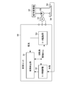
- an electric oil pump 55 is driven by a motor 54 to supply oil in an oil pan 56 to a cooled device 57.
- the machine is cooled (see paragraphs 0014 and 0015, FIG. 1).
- the electric oil pump 55 is a hydraulic pressure source for the transmission of the idle stop system, and requires accurate flow rate control. For this reason, in the control unit 50, the motor control unit 52 sets a drive duty based on the motor rotation speed fed back from the motor 54, and the motor drive unit 53 drives the motor 54 based on the drive duty. .
- the failure detection unit 51 reduces the amount of oil in the oil pan 56 based on the phase current (current) of the motor 54, the rotation speed, and the temperature (oil temperature) of the oil (oil) detected by the temperature sensor 58.
- the light load abnormality such as the oil leakage from the hydraulic piping and the idling of the electric oil pump 55 is determined.
- the cooling system described in Patent Document 1 has a high oil temperature for the purpose of avoiding that the difference in motor current between when the electric oil pump is normal and when idling occurs is reduced and it is difficult to make a determination based on the motor current. Only when the engine is in the idle state, the target rotational speed is increased from the required rotational speed in the idling determination, and the rotational speed of the electric oil pump is intentionally increased. Is controlled to enlarge the difference in motor current (see paragraphs 0074 and 0075, FIG. 10).
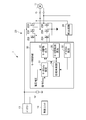
- an electric oil pump controller 61 drives an electric oil pump 65 by a motor 64, sucks oil from an oil pan 66, and supplies oil to a cooled device 68 via an oil cooler 67.
- the motor and generator for vehicles which are the to-be-cooled apparatuses 68 are cooled.
- the control unit 63 sets the drive duty corresponding to the oil temperature detected by the oil temperature sensor 69 by the microcomputer 631, and the electric oil pump controller 61 drives the motor 64 based on the drive duty.
- the flow rate of the oil pump 65 is controlled.
- a pressure sensor 70 for detecting pressure (hydraulic pressure) in the hydraulic piping is provided, and the microcomputer 631 of the control unit 63 is operated by an electric oil pump based on the hydraulic pressure detected by the pressure sensor 70.
- a configuration for detecting 65 load abnormalities is also conceivable. In this case, there is a problem that the pressure sensor 70 is necessary and expensive.
- the present invention has been made to solve the conventional problems as described above, and provides a light load abnormality determination method for an electric oil pump that can reliably prevent erroneous determination regarding light load abnormality with an inexpensive configuration.
- the purpose is to do.
- one aspect of a light load abnormality determination method for an electric oil pump is an electric oil pump that circulates oil to an object to be cooled by an electric oil pump driven by a motor.
- a light load abnormality determination step of determining a light load abnormality of the electric oil pump based on the load evaluation value.
- Pipe resistance equivalent value first coefficient ⁇ current ⁇ voltage / rotation speed 2 (1)
- Reciprocal value of pipe resistance equivalent value second coefficient x rotational speed 2 / (current x voltage) (2)
- the light load abnormality determination step compares the load evaluation value with a threshold and is on a side of the threshold. It is assumed that a light load abnormality of the electric oil pump is determined.
- one aspect of the light load abnormality determination method for the electric oil pump according to the present invention further includes a threshold setting step for setting the threshold.
- the threshold setting step sets the threshold corresponding to the pipe resistance equivalent value
- the light load abnormality determination step includes the calculation.
- the threshold setting step sets the threshold corresponding to an inverse value of the pipe resistance equivalent value
- the light load abnormality determination step includes The light load abnormality is determined when the reciprocal value of the pipe resistance equivalent value calculated in the calculation step is larger than the threshold value.
- the threshold setting step sets the threshold corresponding to the pipe resistance equivalent value corresponding to the oil temperature, and the light load In the abnormality determination step, the light load abnormality is determined when the pipe resistance equivalent value calculated in the calculation step is smaller than the threshold value.
- the threshold setting step sets the threshold corresponding to an inverse value of the pipe resistance equivalent value corresponding to the temperature of the oil, In the light load abnormality determination step, the light load abnormality is determined when the reciprocal value of the pipe resistance equivalent value calculated in the calculation step is larger than the threshold value.
- one aspect of the light load abnormality determination method for the electric oil pump according to the present invention includes a drive duty change step for changing the drive duty of the motor, and the load evaluation corresponding to the change in the drive duty within a predetermined change range.
- a change amount calculating step for calculating a change amount of the value, wherein the light load abnormality determination step determines a light load abnormality of the electric oil pump based on the change amount of the load evaluation value. Yes.
- the present invention it is possible to provide a light load abnormality determination method for an electric oil pump that can reliably prevent an erroneous determination regarding a light load abnormality with an inexpensive configuration.
- FIG. 1 It is a figure which shows schematic structure of the cooling system to which the light load abnormality determination method which concerns on one embodiment of this invention is applied. It is a block diagram which shows the function structure of the motor control part of the cooling system of FIG. It is a figure which shows the timing chart of the drive control signal of the motor in the motor control part of FIG. It is a block diagram which shows the function structure of the failure control part of the cooling system which concerns on Example 1 and 2.
- FIG. It is a figure which shows the change characteristic of the drive duty and piping resistance equivalent value of the cooling system which concerns on Example 1.
- FIG. It is a figure which shows the change characteristic of the reciprocal value of the drive duty and piping resistance equivalent value of the cooling system which concerns on Example 2.
- FIG. 1 It is a figure which shows the change characteristic of the drive duty and motor drive current for verifying the light load abnormality determination method of the cooling system which concerns on Example 1 and 2.
- FIG. It is a figure which shows the change characteristic of the motor rotation speed for verifying the light load abnormality determination method of the cooling system which concerns on Example 1 and 2, and a motor drive current.
- FIG. It is a figure which shows the change characteristic of the oil temperature of a cooling system which concerns on Example 3, and piping resistance equivalent value. It is a figure which shows the change characteristic of the reciprocal value of the oil temperature of the cooling system which concerns on Example 4, and piping resistance equivalent value.
- FIG. 5 It is a block diagram which shows the function structure of the failure control part of the cooling system which concerns on Example 5 and 6.
- FIG. It is a figure which shows the light load determination timing chart in the failure control part of the cooling system which concerns on Example 5 and 6.
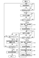
- FIG. It is a figure which shows the flowchart which shows the light load abnormality detection process in the failure control part of the cooling system which concerns on Example 5.
- FIG. It is a figure which shows the change characteristic of the reciprocal value of piping resistance equivalent value at the time of light load abnormality determination of the cooling system which concerns on a present Example.
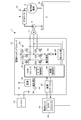
- FIG. 1 is a diagram showing a schematic configuration of a cooling system to which a light load abnormality determination method according to an embodiment of the present invention is applied.
- the cooling system 1 is suitable, for example, for a vehicle that is mounted on a hybrid vehicle and cools a vehicle motor or a generator (generator) that is a device to be cooled 5 by circulating cooling oil.
- the cooling system 1 includes a cooling mechanism unit 10, a motor 11, an electric oil pump controller 12, a battery circuit 13, and a control unit 14.
- the cooling mechanism unit 10 includes an oil pan 2, an electric oil pump 3, an oil cooler 4, an apparatus to be cooled 5, and an oil temperature sensor 6.
- the electric oil pump 3 is, for example, a rotary volume change pump, and sucks the cooling oil stored in the oil sump of the oil pan 2 and discharges it to the downstream pipe.
- the cooling oil is pumped to the cooled device 5 via the.
- the oil cooler 4 dissipates the heat of the oil passing therethrough.
- the device to be cooled 5 is an object to be cooled such as a motor for a vehicle or a generator, and is cooled by the oil pumped from the electric oil pump 3.
- the oil that has cooled the device to be cooled 5 is returned to the oil pan 2.
- the oil temperature sensor 6 is provided in the oil pan 2 and detects the temperature (oil temperature) of the cooling oil stored in the oil reservoir of the oil pan 2 and controls an oil temperature signal indicating the detected oil temperature.
- the unit 14 is supplied.
- the motor 11 is a sensorless brushless DC motor, and drives the electric oil pump 3 under the control of a motor control unit 30 provided in a microcomputer 21 described later of the electric oil pump controller 12.
- the electric oil pump controller 12 performs overall control of the cooling system 1 related to the driving of the motor 11 and the detection of a failure (light load abnormality) of the electric oil pump 3 in accordance with a command from the control unit 14 which is a host controller. Do.
- the battery circuit 13 is a secondary power source for supplying operating power to the electric oil pump controller 12 and a microcomputer 21 described later in the electric oil pump controller 12.
- the control unit 14 has a microcomputer 141.
- the microcomputer 141 is composed of, for example, a general-purpose microcomputer, and the CPU executes a control program and performs various processes. For example, the microcomputer 141 generates various commands for driving the motor 11 based on the driving state of the vehicle, the oil temperature signal from the oil temperature sensor 6, etc., and sends the commands to the microcomputer 21. It functions as a host controller of the electric oil pump controller 12.
- the electric oil pump controller 12 includes a microcomputer 21, a power circuit 22, a drive circuit 23, a detection circuit 24, a current measurement circuit 25, a voltage measurement circuit 26, and a communication interface circuit 27. .
- the microcomputer 21 includes a CPU, a ROM, a RAM, and the like, and at least the motor control unit 30 and the failure control unit 40 are realized by the CPU executing a control program stored in the ROM. Detailed configurations and operations of the motor control unit 30 and the failure control unit 40 will be described in detail later.
- the power supply circuit 22 converts the voltage supplied from the battery circuit 13 into a DC voltage and supplies it to the microcomputer 21 as an operating power supply.
- the drive circuit 23 includes switching elements 231, 232, 233, 234, 235, and 236 for switching the drive current Ii of each phase of the rotor of the motor 11. Switching of the switching elements 231, 232, 233, 234, 235, 236 is controlled by the motor control unit 30.
- the detection circuit 24 includes a filter, a comparison circuit, a logic circuit, an A / D converter, or the like, and indicates the switching timing of the rotor phase of the motor 11 from the back electromotive force of the non-conduction phase of the motor 11 illustrated in FIG. A zero cross signal is detected and notified to the motor control unit 30.
- the current measurement circuit 25 includes, for example, a resistance element connected to the drive circuit 23 so that the drive current Ii of each phase of the motor 11 can flow and an operational amplifier, and the drive current of each phase flowing through the resistance element.
- the voltage drop corresponding to Ii is converted into a voltage that can be A / D converted.
- the failure control unit 40 can detect the drive current Ii of each phase of the motor 11 based on this voltage drop.
- the voltage measurement circuit 26 is constituted by, for example, a voltage dividing resistor connected between the electric wire between the battery circuit 13 and the drive circuit 23 and GND.
- the voltage measurement circuit 26 converts the voltage applied to the circuit formed by the battery circuit 13, the drive circuit 23, and GND into a voltage that can be A / D converted.
- the failure control unit 40 can detect this voltage drop as the supply motor supply voltage Vi of the motor 11.
- the communication interface circuit 27 communicates with the microcomputer 141 of the control unit 14, acquires a command from the microcomputer 141, and sends a signal indicating the state of the motor 11 from the microcomputer 21 of the electric oil pump controller 12. Or to supply.
- the microcomputer 21 realizes the motor control unit 30 by, for example, the CPU executing a motor control program stored in the ROM.
- the motor control unit 30 includes a motor duty (Duty) setting unit 31, a motor drive output unit 32, a zero cross detection unit 33, a phase angle control unit 34, and a motor rotation number calculation unit 35.
- the motor duty (Duty) setting unit 31 a motor drive output unit 32, a zero cross detection unit 33, a phase angle control unit 34, and a motor rotation number calculation unit 35.
- the motor duty setting unit 31 receives the command duty (duty) from the control unit 14, and takes in the motor supply voltage Vi after correcting the supply motor supply voltage Vi to the motor 11 detected via the voltage measurement circuit 26.
- a new motor drive duty (hereinafter referred to as drive duty) is set based on the corrected motor supply voltage Vi and the command duty.
- the motor drive output unit 32 constitutes a drive circuit 23 with a signal for driving the motor 11 based on the drive duty set by the motor duty setting unit 31 and an energization pattern set by a phase angle control unit 34 described later. It sends out to each switching element 231,232,233,234,235,236, and the motor 11 is rotationally driven.
- the zero cross detection unit 33 detects the zero cross by taking the detection result of the zero cross signal from the detection circuit 24 while the motor 11 is driven to rotate.
- the phase angle control unit 34 sets an energization pattern for the motor drive output unit 32 based on the zero cross signal detected by the zero cross detection unit 33.
- the motor rotation number calculation unit 35 detects the rotation number Ri of the motor 11 based on the result of the phase angle control by the phase angle control unit 34.
- the motor rotation speed calculation unit 35 detects the drive current Ii flowing in each phase (U, V, W phase) during driving of the motor 11 from the above-described phase angle control result.
- the configuration may be such that the rotational speed Ri or rotational position of the motor 11 is detected using a sensor signal of an encoder or the like.
- the motor duty setting unit 31 acquires a command duty from the control unit 14 and sets a drive duty based on the command duty.
- the motor duty setting unit 31 measures the supply motor supply voltage Vi from the battery circuit 13 to the motor 11 and corrects the voltage.
- the motor drive output unit 32 drives the motor 11 with the drive duty set by the motor duty setting unit 31.
- the zero-cross detector 33 detects the zero-cross by taking the detection result of the zero-cross signal (see FIG. 3) in the detection circuit 24.
- the phase angle control unit 34 sets an energization pattern for driving the motor 11 based on the detection of the zero cross signal by the zero cross detection unit 33.
- the motor drive output unit 32 controls the drive of the motor 11 by instructing an energization pattern to the drive circuit 23.
- the motor rotation number calculation unit 35 calculates the rotation number of the motor 11 from the phase angle controlled by the phase angle control unit 34.
- the motor control unit 30 controls the rotation speed of the motor 11 by sequentially switching the U, V, W and u, v, w energization patterns of the drive circuit 23 according to the energization pattern of FIG. It has become.
- the motor control unit 30 controls the drive current Ii of the motor 11 by controlling the pulse width of the PWM drive duty of the u, v, and w of the drive circuit 23 to control the drive torque of the motor 11. It has become.
- the microcomputer 21 implements the failure control unit 40 by the CPU executing, for example, a failure detection control program stored in the ROM.
- the failure control unit 40 is, for example, a light load abnormal state in which the load on the electric oil pump 3 is reduced, for example, when the oil in the lower part of the generator 5 is exhausted or when the suction / discharge side piping is disconnected. Is detected.
- the failure control unit 40 detects a current (phase current) Ii flowing through the motor 11, a motor supply voltage Vi supplied to the motor 11, and a rotation speed Ri of the motor 11, and a detection step.
- the load evaluation value for light load abnormality determination is the pipe resistance equivalent value expressed by the following equation (1) or the following equation (2): A calculation step for calculating an inverse value of the pipe resistance equivalent value represented, and a light load abnormality determination step for determining a light load abnormality of the electric oil pump 3 based on the load evaluation value. It is.
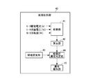
- FIG. 4 is a block diagram illustrating a functional configuration of the failure control unit 40 of the cooling system 1 according to the first embodiment.
- the failure control unit 40 according to the first embodiment includes an inspection unit 41, a calculation unit 42, a threshold setting unit 43, a light load abnormality determination unit 44, and an abnormality notification unit 45.
- the inspection unit 41 correctly acquires the current (phase current) Ii flowing through the motor 11, the motor supply voltage Vi supplied to the motor 11, and the rotation number Ri of the motor 11 while the motor 11 is driven based on the control of the motor control unit 30. An inspection process is performed to inspect whether or not
- the inspection unit 41 determines the voltage across the current measurement circuit 25 when the drive current Ii flowing through the switching elements 231-236 of the drive circuit 23 flows to the current measurement circuit 25 during the driving of the motor 11.
- a current flowing through the motor 11 (hereinafter also referred to as a motor drive current) Ii is detected by amplification with an operational amplifier and A / D conversion (see FIG. 4).
- the inspection unit 41 divides the voltage applied to the circuit formed between the battery circuit 13, the drive circuit 23, and GND during the driving of the motor 11 by the voltage measurement circuit 26, and the A / D By converting, it is detected as a voltage supplied to the motor 11 (hereinafter also referred to as a motor supply voltage) Vi (see FIG. 4).
- the inspection unit 41 rotates the motor 11 calculated by the motor rotation number calculation unit 35 of the motor control unit 30 while the motor 11 is being driven (hereinafter also referred to as a motor rotation number). Ri is taken in (see FIG. 4).
- the inspection unit 41 detects (inspects) the drive current Ii, the motor supply voltage Vi, and the motor rotation number Ri in a state while the motor 11 is being driven.
- the calculation unit 42 calculates a load evaluation for evaluating the load of the electric oil pump 3 based on the drive current Ii, the motor supply voltage Vi, and the motor rotation number Ri inspected by the inspection unit 41. In the present embodiment, the calculation unit 42 calculates a pipe resistance equivalent value or an inverse value of the pipe resistance equivalent value as a load evaluation value of the electric oil pump 3.
- Pipe resistance equivalent value first coefficient ⁇ (Ii) ⁇ (Vi) / (Ri) 2 (1)
- first coefficient and the second coefficient in the above expressions (1) and (2) can be set to different appropriate values. Further, in the above formulas (1) and (2), when the motor 11 is driven with the motor supply voltage Vi supplied to the motor 11 being constant, the motor supply voltage Vi is omitted and the first coefficient, A calculation formula in which each coefficient is replaced with another coefficient can be used.
- the threshold setting unit 43 compares the pipe resistance equivalent value calculated as the load evaluation value by the calculation unit 42 or an inverse value of the pipe resistance equivalent value (hereinafter referred to as 1 / pipe resistance equivalent value) for electric A threshold value used for determining whether or not the light load of the oil pump 3 is abnormal is set.
- the light load abnormality determination unit 44 compares the pipe resistance equivalent value calculated by the calculation unit 42 or the 1 / pipe resistance equivalent value with the threshold value for light load abnormality determination set by the threshold setting unit 43. Then, based on the comparison result, it is determined whether or not a light load abnormality of the electric oil pump 3 has occurred.
- the abnormality notification unit 45 When the light load abnormality determination unit 44 determines that a light load abnormality has occurred in the electric oil pump 3, the abnormality notification unit 45 notifies that fact.
- the abnormality notification unit 45 can be configured to display that a light load abnormality has occurred on a display unit including a speedometer or the like.
- the abnormality notification part 45 can also be set as the structure which outputs a warning sound with the said display.
- the abnormality notification unit 45 may be configured to send an abnormality occurrence signal to the engine ECU, for example, and to perform control to stop the traveling of the hybrid vehicle by the engine ECU.
- the calculation unit 42 calculates the load evaluation value of the electric oil pump 3 based on the drive current Ii, the motor supply voltage Vi, and the motor rotation number Ri that are inspected by the inspection unit 41.
- the pipe resistance equivalent value is calculated by the above equation (1).
- the threshold setting unit 43 sets an appropriate value of the pipe resistance equivalent value as a threshold for light load abnormality determination prior to the light load abnormality determination processing of the electric oil pump 3.
- the threshold setting unit 43 is, for example, based on the change characteristic of the drive duty and pipe resistance equivalent value shown in FIG. 5 (hereinafter referred to as drive duty / pipe resistance equivalent value characteristic) in a drive duty range of 30-80%.
- drive duty / pipe resistance equivalent value characteristic the change characteristic of the drive duty and pipe resistance equivalent value shown in FIG. 5
- One appropriate pipe resistance equivalent value that can be used in common is set as the threshold value.
- the characteristics P11, P12, and P13 are normal when the oil temperature is 30 degrees, 40 degrees, and 50 degrees, respectively, and no light load abnormality has occurred.
- the change characteristics are shown.
- characteristics P15, P16, and P17 indicate change characteristics when the light load is abnormal.
- the light load abnormality of the electric oil pump 3 is within the range of the oil temperature of 30 to 50 degrees and within the range of the drive duty of 30 to 80%.
- the pipe resistance equivalent value calculated during the driving of the motor 11 is on either side of the threshold value. It can be seen that it is possible to determine whether there is a light load abnormality or not.
- the failure control unit 40 executes a light load abnormality determination process for the electric oil pump 3 according to the following flow.
- the inspection unit 41 inspects whether the drive current Ii, the motor supply voltage Vi, and the motor rotation number Ri are normally detected or acquired.
- the calculation unit 42 applies the above equation (1) based on the drive current Ii, the motor supply voltage Vi, and the motor rotational speed Ri to obtain the pipe resistance equivalent value. calculate.
- the light load abnormality determination unit 44 determines that the light load abnormality is normal, and if the pipe resistance equivalent value is below the threshold value, a light load abnormality has occurred. (See FIG. 5).
- the abnormality notification unit 45 When it is determined by the light load abnormality determination unit 44 that a light load abnormality has occurred, the abnormality notification unit 45 further performs control to notify that a light load abnormality has occurred.
- the failure control unit 40 of the cooling system 1 is the inspection unit 41, and the drive current Ii that flows through the motor 11 that drives the electric oil pump 3 and the motor supply voltage Vi that is supplied to the motor 11. And a detection step for detecting the rotational speed Ri of the motor 11, and the calculation unit 42 based on the driving current Ii, the motor supply voltage Vi and the rotational speed Ri detected in the detection step, to calculate the pipe resistance equivalent value as a load evaluation value.
- the light load of the electric oil pump 3 based on the comparison result between the calculation step calculated as follows and the load evaluation value calculated in the calculation step and the threshold set by the threshold setting unit 43 in the light load abnormality determination unit 44
- the light load abnormality determination step for determining abnormality is executed.
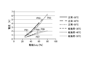
- FIG. 8 shows the motor rotation speed / current characteristics.
- characteristics P81, P82, and P83 indicate change characteristics at normal times when the oil temperatures are 30 degrees, 40 degrees, and 50 degrees, respectively, and there is no load abnormality.
- characteristics P85, P86, and P87 indicate change characteristics when the oil temperatures are 30 degrees, 40 degrees, and 50 degrees, respectively, and when the load is abnormal.
- the normal characteristics P81, P82, and P83 and the light load abnormal characteristics P85, P86, and P87 are within the range of the oil temperature of 30 to 50 degrees. This is a characteristic in which the difference between the two becomes smaller as becomes smaller.
- a common 1 is obtained between the normal characteristics P81, P82, and P83 and the light load abnormal characteristics P85, P86, and P87 through a 30 to 80% drive duty region. There is no difference area with a width that can set two thresholds.
- the light load abnormality determination threshold when a value near the middle between the normal value and the light load abnormality (current value) is set as the light load abnormality determination threshold, Since the determination range of the current value at the normal time and when the light load is abnormal is small in the region where the drive duty is small, the normal state is likely to be erroneously determined as the light load abnormal state. In order to eliminate this, it is necessary to set a threshold value corresponding to the drive duty. In this case, the light load abnormality determination process depends on the drive duty.
- characteristics P91, P92, and P93 indicate change characteristics when the oil temperatures are 30 degrees, 40 degrees, and 50 degrees, respectively, and are normal.
- P96, and P97 indicate the change characteristics when the load is abnormal.
- the normal characteristics P91, P92, and P93 and the light load abnormal characteristics P95, P96, and P97 in the oil temperature range of 30 to 50 degrees are the motor speed. This is a characteristic in which the difference between the two becomes smaller as becomes smaller.
- this motor speed / current characteristic is also common between the normal characteristics P91, P92, and P93 and the light load abnormal characteristics P95, P96, and P97 through the drive duty range of 30 to 80 percent. There is no difference area where one threshold can be set.
- the light load abnormality determination process has to depend on the drive duty.
- the threshold value set by the threshold value setting unit 43 is determined based on the drive duty / pipe resistance equivalent value characteristics shown in FIG. One pipe resistance equivalent value common to the drive duty range of 80 percent.
- the threshold value for light load abnormality determination is, for example, the value of the pipe resistance equivalent value between the characteristics P13 and P15 in the drive duty / pipe resistance equivalent value characteristic shown in FIG. For example, by setting one value such as “700”, it is possible to accurately determine whether or not the light load is abnormal depending on whether or not the threshold is exceeded.
- the rotational speed Ri is small, that is, when the duty is small, the difference in the pipe resistance equivalent value between the characteristics P13 and P15 is large, so an accurate light load abnormality determination can be performed.
- the failure control unit 40 it is possible to avoid erroneously determining the normal state as a light load abnormality without depending on the drive duty.
- the cooling system 1 according to the second embodiment includes a failure control unit 40 having the same configuration as the cooling system 1 according to the first embodiment.
- the calculation unit 42 calculates the load evaluation value of the electric oil pump 3 based on the drive current Ii, the motor supply voltage Vi, and the motor rotation number Ri inspected by the inspection unit 41.
- the 1 / pipe resistance equivalent value is calculated by the above equation (2).
- the threshold setting unit 43 sets an appropriate value of 1 / pipe resistance equivalent value as a threshold for light load abnormality determination prior to the light load abnormality determination processing of the electric oil pump 3.
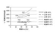
- the threshold setting unit 43 is, for example, 30-80% based on the change characteristic of the drive duty and 1 / pipe resistance equivalent value (hereinafter, drive duty / 1 / pipe resistance equivalent value characteristic) shown in FIG.
- drive duty / 1 / pipe resistance equivalent value characteristic 1 / pipe resistance equivalent value that can be commonly used in the drive duty range is set as the threshold value.
- the characteristics P21, P22, and P23 are when the oil temperature is 30 degrees, 40 degrees, and 50 degrees, respectively, and no light load abnormality occurs.
- the change characteristics at normal time are shown.
- the characteristics P25, P26, and P27 show the change characteristics when the light load is abnormal.
- the electric oil pump 3 is light within the range of the oil temperature of 30 to 50 degrees and the driving duty of 30 to 80%.
- a pipe resistance equivalent value between the normal value and the abnormal value in FIG. 6 is set, so that the pipe resistance equivalent value calculated while the motor 11 is driven is on either side of the threshold value. It can be seen that it is possible to determine whether there is a light load abnormality or not.
- the failure control unit 40 executes a light load abnormality determination process for the electric oil pump 3 according to the following flow.
- the inspection unit 41 inspects whether the drive current Ii, the motor supply voltage Vi, and the motor rotation number Ri are normally detected or acquired.
- the calculation unit 42 applies the above equation (2) based on the drive current Ii, the motor supply voltage Vi, and the motor rotational speed Ri, and 1 / Calculate the pipe resistance equivalent value.
- the light load abnormality determination unit 44 determines that the light load abnormality is normal. If the 1 / pipe resistance equivalent value is above the threshold value, the light load abnormality is determined. Is determined to occur (see FIG. 6).
- the abnormality notification unit 45 When it is determined by the light load abnormality determination unit 44 that a light load abnormality has occurred, the abnormality notification unit 45 further performs control to notify that a light load abnormality has occurred.
- the threshold value set by the threshold value setting unit 43 is 30-80% determined based on the drive duty / 1 / pipe resistance equivalent value characteristic shown in FIG. One 1 / pipe resistance equivalent value common to the drive duty range.
- the threshold for light load determination for example, the value of 1 / pipe resistance equivalent value between the characteristics P23 and P25 in the drive duty / 1 / pipe resistance equivalent value characteristic shown in FIG. More specifically, for example, by setting one value such as “1500”, it is possible to accurately determine whether or not the light load is abnormal depending on whether or not the threshold is exceeded. That is, also in this embodiment, by including the failure control unit 40, the normal state is erroneously determined as a light load abnormality without depending on the drive duty as in the conventional electric oil pump control device illustrated in FIG. Can be avoided.
- FIG. 9 is a block diagram illustrating a functional configuration of the failure control unit 40A of the cooling system 1 according to the third embodiment.
- the same components as those in the first and second embodiments are denoted by the same reference numerals, and detailed description thereof is omitted.
- the configuration different from the first and second embodiments is mainly described. Explained.
- the failure control unit 40A includes an inspection unit 41, a calculation unit 42, a threshold setting unit 43A, a light load abnormality determination unit 44A, and an abnormality notification unit 45.
- the calculation unit 42 is configured to calculate a pipe resistance equivalent value as the load evaluation value of the electric oil pump 3 by the above equation (1).
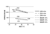
- the threshold setting unit 43A uses, for example, a change characteristic of the oil temperature and the pipe resistance equivalent value (hereinafter, oil temperature / pipe resistance equivalent value characteristic) shown in FIG. 10 as the threshold for the light load abnormality determination process of the electric oil pump 3. Based on this, a pipe resistance equivalent value corresponding to the oil temperature is set as a threshold value.
- the characteristics P31, P32, and P33 are normal when the drive duty is 40%, 50%, and 60%, respectively, and no light load abnormality has occurred.
- the characteristics P35, P36, and P37 indicate the change characteristics when the light load is abnormal.
- the pipe resistance equivalent values are always larger in the normal characteristics P31, P32, and P33 than in the light load abnormality characteristics P35, P36, and P37.
- all of the normal characteristics P31, P32, and P33 and the light load abnormal characteristics P35, P36, and P37 are such that the higher the oil temperature, the smaller the value, and the lower the oil temperature, the wider the difference between the two. Have.
- the threshold setting unit 43A corresponds to the continuous pipe resistance corresponding to the oil temperature based on the oil temperature / pipe resistance equivalent value characteristic shown in FIG. A description will be given based on an example in which a value is set as the threshold value.
- the light load abnormality determination unit 44A detects the oil detected by the oil temperature sensor 6 at that time among the pipe resistance equivalent value calculated by the calculation unit 42 and the threshold value set by the threshold value setting unit 43A.
- a light load abnormality of the electric oil pump 3 is determined by comparing with a threshold value corresponding to the oil temperature indicated by the temperature signal.
- the light load abnormality determination unit 44A acquires the oil temperature signal from the microcomputer 141 of the control unit 14 through the communication interface circuit 27 (see FIG. 9).
- the threshold setting unit 43A is based on the oil temperature / pipe resistance equivalent value characteristics shown in FIG. A continuous pipe resistance equivalent value corresponding to the oil temperature is set as a threshold value.
- the failure control unit 40A executes a light load abnormality determination process for the electric oil pump 3 according to the following flow.
- the inspection unit 41 inspects whether the drive current Ii, the motor supply voltage Vi, and the motor rotation number Ri are normally detected or acquired.
- the calculation unit 42 applies the above equation (1) based on the drive current Ii, the motor supply voltage Vi, and the motor rotation speed Ri, and then performs piping at this time. The resistance equivalent value is calculated.
- the light load abnormality determination unit 44A acquires the oil temperature signal transmitted from the microcomputer 141 of the control unit 14 through the communication interface circuit 27 while taking in the pipe resistance equivalent value calculated by the calculation unit 42. Further, the light load abnormality determination unit 44A reads a threshold value corresponding to the oil temperature indicated by the oil temperature signal among the threshold values set by the threshold value setting unit 43A, and obtains the detected threshold value and the pipe resistance equivalent value. A comparison is made and it is determined whether or not there is a light load abnormality based on the comparison result.
- the light load abnormality determination unit 44A determines that it is in a normal state, and if the calculated pipe resistance equivalent value is below the threshold value, the light load abnormality determination unit 44A is light. It is determined that a load abnormality has occurred (see FIG. 10).
- the abnormality notification unit 45 When it is determined by the light load abnormality determination unit 44A that a light load abnormality has occurred, the abnormality notification unit 45 further performs control to notify that a light load abnormality has occurred.
- the driving current Ii that flows through the motor 11 that drives the electric oil pump 3 and the motor supply voltage Vi that is supplied to the motor 11 by the inspection unit 41.
- a detection step for detecting the rotational speed Ri of the motor 11, and the calculation unit 42 based on the driving current Ii, the motor supply voltage Vi and the rotational speed Ri detected in the detection step, to calculate the pipe resistance equivalent value as a load evaluation value.
- the light load abnormality determination unit 44 detects the load evaluation value calculated in the calculation step and the threshold value set by the threshold value setting unit 43 corresponding to the oil temperature at this time.
- a process including a light load abnormality determination step for determining a light load abnormality of the electric oil pump 3 based on a comparison result with a threshold value corresponding to the oil temperature is executed. You have me.
- the threshold values set by the threshold value setting unit 43A of the failure control unit 40A are, as shown in FIG. 10, the normal characteristics P31, P32, P33 and the light load abnormality characteristics P35, P36, P37.
- This is a continuous pipe resistance equivalent value corresponding to the oil temperature, determined based on the oil temperature / pipe resistance equivalent value characteristic having a large difference.
- the normal state is erroneously determined as a light load abnormality without depending on the drive duty as in the conventional electric oil pump control device shown in FIG. You can avoid that.
- the light load is reduced. The abnormality determination accuracy can be improved.
- the cooling system 1 according to the fourth embodiment includes a failure control unit 40A (see FIG. 9) having the same configuration as the cooling system 1 according to the third embodiment.
- the calculation unit 42 calculates the load evaluation value of the electric oil pump 3 based on the drive current Ii, the motor supply voltage Vi, and the motor rotation number Ri inspected by the inspection unit 41.
- the 1 / pipe resistance equivalent value is calculated by the above equation (2).
- the threshold setting unit 43A sets a continuous appropriate 1 / pipe resistance equivalent value as a threshold for light load abnormality determination prior to the light load abnormality determination processing of the electric oil pump 3.
- the threshold setting unit 43A corresponds to the oil temperature based on, for example, the change characteristic of the oil temperature and the 1 / pipe resistance equivalent value (hereinafter referred to as oil temperature / 1 / pipe resistance equivalent value characteristic) shown in FIG. 1 / Pipe resistance equivalent value is set as a threshold value.
- characteristics P41, P42, and P43 are when the drive duty is 40%, 50%, and 60%, respectively, and no light load abnormality has occurred.
- the change characteristics at normal time are shown, and the characteristics P45, P46, and P47 show the change characteristics at the time of light load abnormality.
- the 1 / pipe resistance equivalent values are always greater than the normal characteristics P41, P42, and P43 than the characteristics P45, P46, and P47 when the light load is abnormal. small. Further, all of the normal characteristics P41, P42, and P43 and the light load abnormal characteristics P45, P46, and P47 are larger as the oil temperature is higher, and the difference between the two is larger as the oil temperature is higher.
- the threshold setting unit 43A dares to set a continuous 1 / pipe resistance equivalent value corresponding to the oil temperature as the threshold based on the oil temperature / 1 / pipe resistance equivalent value characteristic shown in FIG.
- the light load abnormality determination unit 44A calculates the 1 / pipe resistance equivalent value calculated by the calculation unit 42 and the threshold value corresponding to the oil temperature at the time point among the threshold values set by the threshold value setting unit 43A. In comparison, a light load abnormality of the electric oil pump 3 is determined.
- the failure control unit 40A sets the threshold value setting unit 43A to the oil temperature / 1 / pipe resistance equivalent value characteristic shown in FIG. Based on this, a continuous pipe resistance equivalent value corresponding to the oil temperature is set as a threshold value.
- the failure control unit 40A executes a light load abnormality determination process for the electric oil pump 3 according to the following flow.
- the inspection unit 41 inspects whether the drive current Ii, the motor supply voltage Vi, and the motor rotation number Ri are normally detected or acquired.
- the calculating unit 42 applies the above equation (2) based on the drive current Ii, the motor supply voltage Vi, and the motor rotation number Ri, and then calculates 1 at this time. / Calculate the pipe resistance equivalent value.
- the light load abnormality determining unit 44A acquires the oil temperature signal transmitted from the microcomputer 141 of the control unit 14 through the communication interface circuit 27 while taking in the 1 / pipe resistance equivalent value calculated by the calculating unit 42. . Further, the light load abnormality determination unit 44A reads a threshold value corresponding to the oil temperature indicated by the oil temperature signal among the threshold values set by the threshold value setting unit 43A, and the 1 / pipe resistance equivalent value detected as the threshold value. And whether or not there is a light load abnormality is determined based on the comparison result.
- the light load abnormality determination unit 44A determines that it is in a normal state, and the calculated 1 / pipe resistance equivalent value is above the threshold value. If it is, it is determined that a light load abnormality has occurred (see FIG. 11).
- the abnormality notification unit 45 When it is determined by the light load abnormality determination unit 44A that a light load abnormality has occurred, the abnormality notification unit 45 further performs control to notify that a light load abnormality has occurred.
- the threshold values set by the threshold value setting unit 43 of the failure control unit 40A are normal characteristics P41, P42, and P43 and light load abnormal characteristics P45, P46, and P47.
- This is a continuous 1 / pipe resistance equivalent value corresponding to the oil temperature, which is determined based on the oil temperature / 1 / pipe resistance equivalent value characteristic having a large difference.
- the normal state is erroneously determined as a light load abnormality without depending on the drive duty as in the conventional electric oil pump control device shown in FIG. You can avoid that.
- a continuous 1 / pipe resistance equivalent value corresponding to the oil temperature is set, compared to the case where one 1 / pipe resistance equivalent value is set as a threshold as in the second embodiment.
- the light load abnormality determination accuracy can be improved.
- FIG. 12 is a block diagram illustrating functional configurations of the failure control unit 40B and the motor control unit 30B of the cooling system 1 according to the fifth embodiment.
- the same components as those of the first to fourth embodiments are denoted by the same reference numerals, and detailed description thereof is omitted.
- a configuration different from the first to fourth embodiments is mainly described. Explained.
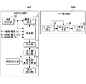
- the failure control unit 40B of the present embodiment includes a light load abnormality determination unit in addition to the inspection unit 41, the calculation unit 42, the threshold setting unit 43, and the abnormality notification unit 45 equivalent to those of the first to fourth embodiments. 44B, an inspection control unit 46, a superimposition duty setting unit 47, and a change amount calculation unit 48.
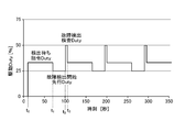
- the inspection control unit 46 performs control for a light load abnormality determination inspection (hereinafter referred to as inspection) for determining a light load abnormality based on the amount of change in the load evaluation value when the motor drive duty is changed. Specifically, for example, based on the light load determination timing chart shown in FIG. 13, the inspection control unit 46 recognizes the period of time t0-t1 as the detection waiting command duty period, and then continues the period of time t1-t2. In the period of time t2-t3, the preceding duty setting command and the inspection duty setting for superimposing the failure detection start preceding duty (hereinafter referred to as the preceding duty) and the failure detection inspection duty (hereinafter referred to as the inspection duty), respectively. The command is sent to the superimposed duty setting unit 47.
- inspection a light load abnormality determination inspection
- the superimposing duty setting unit 47 sets a preceding duty and a testing duty to be superimposed on the command duty based on the preceding duty setting command and the inspection duty setting command from the inspection control unit 46, respectively.
- the 30B inspection duty superimposing unit 36 is instructed to superimpose these set duties.
- the change amount calculation unit 48 is a load evaluation value when the motor 11 is driven by the inspection duty superimposition unit 36 with the preceding duty and the inspection duty superimposed on the detection wait command duty. The amount of change is calculated.
- the change amount of the load evaluation value between the preceding duty superimposition time and the inspection duty superposition time detected by the change amount calculation unit 48 after the start of the inspection is set in the threshold setting unit 43. It is determined whether or not the light load is abnormal depending on whether or not the threshold is exceeded.
- the motor control unit 30 ⁇ / b> B of the present embodiment is provided with an inspection duty superimposing unit 36 between the motor duty setting unit 31 and the motor drive output unit 32.
- the configuration of the motor control unit 30B other than the above is the same as that of the motor control unit 30 shown in FIG.
- the inspection duty superimposing unit 36 sets the preceding duty and the inspection duty to the detection waiting command duty that is the driving duty at the time of normal driving set by the motor duty setting unit 31 based on the command from the superimposing duty setting unit 47 of the failure control unit 40B. Control to superimpose duty.
- the calculation unit 42 calculates the load evaluation value of the electric oil pump 3 based on the drive current Ii, the motor supply voltage Vi, and the motor rotational speed Ri that are inspected by the inspection unit 41.
- the 1 / pipe resistance equivalent value is calculated by the above equation (2).
- the threshold setting unit 43 sets an appropriate value of 1 / pipe resistance equivalent value as a threshold for light load abnormality determination prior to the light load abnormality determination processing of the electric oil pump 3.
- the threshold setting unit 43 for example, in the same way as in the second embodiment, for example, in the 1 / pipe resistance equivalent value / drive duty characteristic shown in FIG. Shall be set as
- the failure control unit 40B follows the flowchart shown in FIG. 14 based on the light load abnormality determination timing chart shown in FIG. A light load abnormality determination process of the electric oil pump 3 is executed.
- the inspection control unit 46 monitors the passage of time t1, t2, t3,... Based on the light load abnormality determination timing chart shown in FIG. In addition, the inspection control unit 46 performs variable control of the motor drive duty based on the preceding duty and the inspection duty according to the time being monitored and the time interval.
- the inspection control unit 46 recognizes the section of time t0-t1 in the light load abnormality determination timing chart shown in FIG. 13 as the inspection start waiting section, and during this time, starts the inspection without giving a command for superimposing the preceding duty and the inspection duty.
- the waiting state is maintained (step S11).
- the motor duty setting unit 31 sets a detection wait command duty that is a normal drive duty, and the motor drive output unit 32 sets the motor based on the detection wait command duty. 11 is driven.
- the detection wait command duty is set to a value of 30%, for example (see FIG. 13).
- the inspection control unit 46 determines whether or not the time t1 in the light load abnormality determination timing chart shown in FIG. 13 has been reached, that is, whether or not it is the inspection start time (step S12). If it is determined that it is not the inspection start time (NO in step S12), the inspection control unit 46 maintains the inspection start waiting state in step S11.
- the inspection control unit 46 recognizes that the preceding duty superimposition period has been reached, and causes the superposition duty setting unit 47 to A command is sent, and control for superimposing the preceding duty on the detection waiting command duty is started by the inspection duty superimposing unit 36 (step S13).
- the inspection control unit 46 determines whether or not the time immediately before the time t2 in the light load abnormality determination timing chart shown in FIG. 13 has been reached, that is, whether or not the stabilization wait time for the preceding duty has elapsed (Ste S14). If it is determined that the preceding duty stabilization waiting time has not elapsed (NO in step S12), the inspection control unit 46 continues the preceding duty superimposing process in step S13.
- step S13 the inspection control unit 46 performs control so that the duty after superimposing the preceding duty is lower than the detection waiting command duty, for example, 25%. That is, the inspection control unit 46 performs a process of superimposing a preceding duty of ⁇ 5% on the detection waiting command duty (see FIG. 13).
- step S14 it is determined that the time t2 in the light load abnormality determination timing chart of FIG. 13 has been reached and that the waiting time for stabilization of the preceding duty has elapsed (YES in step S14). Recognizing this, the inspection unit 41 measures the drive current Ii, the motor supply voltage Vi, and the motor rotation number Ri of the motor 11 (step S15), and the calculation unit 42 calculates the load evaluation value based on the measured parameters. 1 / pipe resistance equivalent value is calculated (step S16).
- the inspection control unit 46 recognizes that the inspection duty superimposition period has been reached, and sends a command to the superimposition duty setting unit 47 to check the inspection duty. Control for superimposing the inspection duty on the detection waiting instruction duty is started by the superimposing unit 36 (step S17).
- step S17 the inspection control unit 46 performs control so that the duty after superimposing the inspection duty is higher than the detection wait command duty, for example, 50%. That is, the inspection control unit 46 performs a process of superimposing a + 20% inspection duty on the detection waiting instruction duty (see FIG. 13).
- the inspection control unit 46 determines whether or not the time just before time t3 in the light load abnormality determination timing chart shown in FIG. 13 has been reached, that is, whether or not the inspection duty stabilization wait time has elapsed. If it is determined that the stable waiting time for the inspection duty has not elapsed (NO in step S18), the inspection control unit 46 continues the inspection duty superimposing process in step S17.
- step S18 the inspection unit 41 measures the drive current Ii, the motor supply voltage Vi, and the motor rotation number Ri of the motor 11 (step S19), and the calculation unit 42 calculates the load evaluation value based on the measured parameters. 1 / pipe resistance equivalent value is calculated (step S20).
- the change amount calculation unit 48 is between the 1 / pipe resistance equivalent value calculated by the calculation unit 42 in step S16 and the 1 / pipe resistance equivalent value calculated by the calculation unit 42 in step S20. Is calculated (step S21).
- the inspection control unit 46 stops the control to superimpose the inspection duty, which has been performed since step S17 (step S22).
- the light load abnormality determination unit 44B determines the 1 when the preceding duty is superimposed and the inspection duty is superimposed based on the amount of change of the 1 / pipe resistance equivalent value calculated by the change amount calculation unit 48 in step S21. / The change direction of the pipe resistance equivalent value is detected, and it is determined whether or not the change direction is an abnormal direction (step S23).
- the determination of the change direction can be performed based on, for example, the drive duty / 1 / pipe resistance equivalent value characteristic shown in FIG.
- the drive duty / 1 / pipe resistance equivalent value characteristic shown in FIG. 6 when the drive duty is increased when the light load is normal, the 1 / pipe resistance equivalent value is decreased (decreased). As the value increases, 1 / pipe resistance equivalent value increases (rises). Therefore, in step S23, the light load abnormality determination unit 44B is in a normal state if the change direction of the 1 / pipe resistance equivalent value is the normal direction, that is, the downward direction, and is light if the change direction is the abnormal direction, that is, the upward direction. It can be determined that the load is abnormal.
- step S23 if it is determined that the change direction of the 1 / pipe resistance equivalent value is not an abnormal direction (NO in step S23), the inspection control unit 46 continues the processing from step S11.
- the light load abnormality determination unit 44B changes the load evaluation value calculated in step S21.
- the light load abnormality determination unit 44B determines that the state is normal when the amount of change in the 1 / pipe resistance equivalent value is smaller than the threshold (NO in step S25). Thereby, the light load abnormality determination process returns to the process after step S11. On the other hand, if the amount of change in the 1 / pipe resistance equivalent value is greater than the threshold value, the light load abnormality determination unit 44B determines that a light load abnormality has occurred (YES in step S25).
- the abnormality notification unit 45 When the light load abnormality determination unit 44B determines that a light load abnormality has occurred, the abnormality notification unit 45 further performs control to notify that a light load abnormality has occurred. After notifying the occurrence of the light load abnormality, the series of light load abnormality determination processing ends.
- FIG. 15 shows a change characteristic of 1 / pipe resistance equivalent value (hereinafter also referred to as inspection characteristic) at the time of light load abnormality determination (inspection) based on the light load determination timing shown in FIG. 13 of the cooling system 1 according to the present embodiment.
- FIG. FIG. 14 shows a change characteristic of a value corresponding to 1 / pipe resistance when pipe disconnection occurs particularly in the hydraulic pipe system of the cooling mechanism unit 10.
- a line segment P51 indicated by a dotted line in the lower part indicates a change pattern of the drive duty in FIG.
- a line segment P52 indicated by a solid line at the top indicates an inspection characteristic of a value corresponding to 1 / pipe resistance when an inspection is performed by changing the drive duty with a change pattern indicated by the line segment P51.
- pipe disconnection occurs at that time, that is, near time 300 (seconds). The inspection characteristics resulting from this are shown.
- the cooling system 1 can increase the duty change amount by temporarily reducing the drive duty and then increasing the drive duty. This also contributes to the prevention of certainty.
- the cooling system 1 according to the sixth embodiment includes a failure control unit 40B and a motor control unit 30B (see FIG. 12) having the same configuration as the cooling system 1 according to the fifth embodiment.
- the failure control unit 40B according to the sixth embodiment will be described with a focus on the configuration different from the fifth embodiment, omitting the description of the same parts as the fifth embodiment.
- the calculation unit 42 uses the drive current Ii, the motor supply voltage Vi, and the motor rotational speed Ri inspected by the inspection unit 41 as the load evaluation value of the electric oil pump 3 ( 1) Calculate the pipe resistance equivalent value using the equation.
- the threshold setting unit 43 corresponds to a pipe resistance equivalent to a light load abnormality determination threshold value, for example, based on the drive duty / pipe resistance equivalent value characteristic shown in FIG. 5 prior to the light load abnormality determination process of the electric oil pump 3.
- the amount of change in value “ ⁇ 50” is set as the threshold value.
- the calculation unit 42 calculates a pipe resistance equivalent value as a load evaluation value. .
- step 21 the change amount calculation unit 48 calculates a change amount between the pipe resistance equivalent value calculated in step S16 and the pipe resistance equivalent value calculated in step S20.
- step S23 the light load abnormality determination unit 44B determines that the normal direction is obtained when the change direction of the pipe resistance equivalent value is the upward direction, and the abnormal direction when the change direction is the downward direction. Thereafter, in step S25, the light load abnormality determination unit 44B determines that the pipe resistance equivalent value is normal when the change amount of the pipe resistance equivalent value is larger than the threshold value, and the change amount of the pipe resistance equivalent value is smaller than the threshold value. Is determined to be in a light load abnormal state (see FIG. 5).
- the drive duty is changed while the motor 11 is being driven, and the load evaluation value (pipe resistance equivalent value or 1 / pipe resistance equivalent value) during that time is changed. ) Is calculated, and light load abnormality is determined based on a comparison result between the change amount of the load evaluation value and the threshold value.
- a light load abnormality can be determined without using a pressure sensor as in the first to fourth embodiments.
- an oil temperature sensor is unnecessary, and it is possible to determine a light load abnormality without depending on the oil temperature, that is, without oil temperature data.
- the configurations of the fifth and sixth embodiments are configured to determine a light load abnormality with one threshold value related to the pipe resistance equivalent value or the 1 / pipe resistance equivalent value according to the first and second embodiments, and according to the third and fourth embodiments. It can be used in combination with a configuration for determining a light load abnormality using a continuous pipe resistance equivalent value or 1 / pipe resistance equivalent value set corresponding to the oil temperature as a threshold value. In this case, for example, after applying a method that does not change the drive duty (see Examples 1 to 4) and then applying a method that changes the drive duty (Examples 5 and 6), the normal state is changed to a light load abnormality time. Can be reliably prevented from being erroneously determined.
- the detection step for detecting the drive current Ii flowing through the motor 11, the motor supply voltage Vi supplied to the motor 11, and the rotational speed Ri of the motor 11 are included in the detection step.
- the load evaluation value for light load abnormality determination is represented by the pipe resistance equivalent value represented by the above equation (1) or the above equation (2). 1 / pipe resistance equivalent value calculation step (calculation unit 42) and light load abnormality determination step for determining a light load abnormality of the electric oil pump 3 based on the load evaluation value (light load abnormality determination unit 44, 44A, 44B).
- the light load abnormality determination step is configured to determine the light load abnormality of the electric oil pump 3 depending on which side of the threshold value the load evaluation value is compared with the threshold value.
- the present embodiment further includes a threshold setting step (threshold setting units 43 and 43A) for setting a threshold.
- the determination range can be expanded by setting a value near the middle of the difference between the pipe resistance equivalent value and the 1 / pipe resistance equivalent value as a threshold value, thereby reducing erroneous determination of light load abnormality. become able to.
- the threshold setting step sets a threshold corresponding to the pipe resistance equivalent value, and the light load abnormality determination step is light when the pipe resistance equivalent value calculated in the calculation step is smaller than the threshold. It is determined that the load is abnormal.
- the threshold value for example, based on the drive duty / pipe resistance equivalent value characteristic shown in FIG. 5, a value near the intermediate value of the difference between the normal value and the light load abnormality is set as the threshold value.
- the threshold setting step sets a threshold value corresponding to 1 / pipe resistance equivalent value
- the light load abnormality determination step determines that the 1 / pipe resistance equivalent value calculated in the calculation step is smaller than the threshold value.
- the threshold value For example, based on the drive duty / 1 / pipe resistance equivalent value characteristic shown in FIG. 6, a value near the intermediate value of the difference between the normal value and the light load abnormality is set as the threshold value. By doing so, it is possible to accurately determine whether or not the light load is abnormal depending on whether the detected 1 / pipe resistance equivalent value is above or below the threshold value.
- the threshold setting step sets a threshold corresponding to the pipe resistance equivalent value corresponding to the oil temperature
- the light load abnormality determination step uses the pipe resistance equivalent value calculated in the calculation step as a threshold. If it is smaller than that, it is determined that the light load is abnormal.
- the value near the intermediate value between the normal value and the light load abnormality corresponds to the oil temperature.
- the threshold setting step sets a threshold corresponding to the 1 / pipe resistance equivalent value corresponding to the oil temperature
- the light load abnormality determination step is the 1 / pipe resistance calculated in the calculation step.
- the light load abnormality is determined when the equivalent value is larger than the threshold value.
- the value near the intermediate value of the difference between the normal value and the light load abnormality is set to the oil temperature.
- a drive duty changing step (inspection control unit 46, superimposition duty setting unit 47, inspection duty setting unit 36, S13 and S17 in FIG. 14) for changing the drive duty of motor 11 and a predetermined change are performed.
- a change amount calculation step (change amount calculation unit 48, S21 in FIG. 14) for calculating a change amount of the load evaluation value corresponding to a change in the driving duty of the range, and a light load abnormality determination step (light load abnormality determination)
- the unit 44B and S25 in FIG. 14 are configured to determine a light load abnormality of the electric oil pump 3 based on the change amount of the load evaluation value.
- a light load abnormality is accurately detected without using a pressure sensor or an oil temperature sensor based on the change direction and the change amount of the load evaluation value corresponding to the change of the drive duty in a predetermined change range. Can be determined.
- the present invention is not limited to the above-described embodiment, and various modifications and applications are possible.
- an example of application to a cooling system that cools a vehicle motor or a generator of a hybrid vehicle is given.
- the present invention is not limited to this, and an oil is driven by an electric oil pump driven by a motor. It is applicable to various systems that circulate the gas and supply it to the object to be cooled.
- the present invention can provide a light load abnormality determination method for an electric oil pump that can reliably prevent an erroneous determination related to a light load abnormality with an inexpensive configuration.
- the present invention is useful for all light load abnormality determination methods for an electric oil pump using a brushless DC motor.
Landscapes
- Engineering & Computer Science (AREA)
- Mechanical Engineering (AREA)
- General Engineering & Computer Science (AREA)
- Power Engineering (AREA)
- Physics & Mathematics (AREA)
- General Physics & Mathematics (AREA)
- Computer Hardware Design (AREA)
- Control Of Electric Motors In General (AREA)
- Control Of Positive-Displacement Pumps (AREA)
- Details And Applications Of Rotary Liquid Pumps (AREA)
- Control Of Transmission Device (AREA)
- Lubrication Of Internal Combustion Engines (AREA)
Abstract
安価な構成で、軽負荷異常に関する誤判定を確実に防止可能な電動オイルポンプの軽負荷異常判定方法を提供するために、故障制御部(40)の検査部(41)で、電動オイルポンプ(3)を駆動するモータ(11)に流れる駆動電流Iiと、モータに供給するモータ供給電圧Viと、モータの回転数Riを検出する検出ステップと、算出部(42)で、検出ステップで検出した駆動電流Ii、モータ供給電圧Viおよび回転数Riとに基づき、配管抵抗相当値またはその逆数値を負荷評価値として算出する算出ステップと、軽負荷異常判定部(44)で、算出ステップで算出された負荷評価値と閾値設定部(43)に設定されている閾値との比較結果に基づいて電動オイルポンプの軽負荷異常を判定する軽負荷異常判定ステップと、を有する。
Description
本発明は、電動オイルポンプの軽負荷異常判定方法に関し、特に、圧力センサを用いないで軽負荷異常判定を行う電動オイルポンプの軽負荷異常判定方法に関する。
電動オイルポンプで循環するオイルを冷媒とする冷却システムとして、例えば、アイドルストップ機能付き車両に搭載され、アイドルストップ中、発進クラッチおよび無段変速機等にオイルを供給し続ける構成を有するものが知られている(例えば、特許文献1参照)。
この冷却システムは、図16に示すように、モータ54で電動オイルポンプ55を駆動してオイルパン56内のオイルを被冷却機器57に供給し、被冷却機器57である発進クラッチおよび無段変速機を冷却する構成を有する(段落0014、0015、図1参照)。
この冷却システムにおいて、電動オイルポンプ55は、アイドルストップシステムの変速機に対する油圧源であり、正確な流量制御が必要となる。このため、制御ユニット50では、モータ制御部52が、モータ54からフィードバックしたモータ回転数に基づき駆動デューティを設定し、その駆動デューティに基づきモータ駆動部53がモータ54を駆動するようになっている。
また、故障検出部51は、モータ54の相電流(電流)、回転数、および温度センサ58で検出されたオイル(油)の温度(油温)に基づいてオイルパン56内の油量の減少、油圧系配管からの油漏れ、電動オイルポンプ55の空回り等の軽負荷異常を判定している。
特許文献1に記載の冷却システムは、電動オイルポンプの正常時と空回り発生時とのモータ電流の差が縮小してモータ電流に基づく判定が困難になることを回避する目的で、油温が高温状態にある場合にのみ、空回りの判定に際して目標回転数を要求回転数よりも増大させて、電動オイルポンプの回転数を意図的に増大させることにより、電動オイルポンプの正常時と空回り発生時とのモータ電流の差を拡大させる制御を行っている(段落0074、0075、図10参照)。
しかしながら、特許文献1に記載の電動オイルポンプの負荷異常判定方法によれば、負荷の推定をモータ電流のみで行っているため、電動オイルポンプの正常時と空回り発生時とのモータ電流の差を拡大させるためには、電動オイルポンプの回転数、つまり、駆動デューティを可変制御する必要があった。また、電動オイルポンプの正常時と空回り発生時とのモータ電流の差異は、駆動デューティと電流との関係の傾きの違いとして現れるので、駆動デューティに依存した負荷異常判定しか行えないという問題があった。更に、低温ではオイルの粘性が高く、電動オイルポンプの吸入負圧が大きくなり過ぎるのでモータの回転数を大きくできず、高温状態でしか判定できないという問題点があった。
また、この種の従来の他の冷却システムとしては、例えば、ハイブリッド車に搭載され図17に示すように、被冷却機器68として車両用モータおよびジェネレータを冷却するものもあった。この冷却システムでは、図17に示すように、電動オイルポンプコントローラ61がモータ64により電動オイルポンプ65を駆動し、オイルパン66からオイルを吸い上げ、オイルクーラー67を介して被冷却機器68にオイルを供給することで、被冷却機器68である車両用モータおよびジェネレータを冷却するようになっている。
図17に示す冷却システムでは、アイドルストップシステムの変速機を冷却するシステム(図16参照)ほどには流量制御の精度は要求されない。このため、制御ユニット63は、マイクロコンピュータ631で、油温センサ69により検出される油温に対応する駆動デューティを設定し、電動オイルポンプコントローラ61が駆動デューティに基づきモータ64を駆動することで電動オイルポンプ65の流量制御を行うようになっている。
図17に示す冷却システムにおいては、例えば油圧配管内における圧力(油圧)を検出する圧力センサ70を設け、この圧力センサ70により検出される油圧に基づいて制御ユニット63のマイクロコンピュータ631が電動オイルポンプ65の負荷異常を検出する構成も考えられる。この場合、圧力センサ70が必要となり、高価になるという問題点があった。
本発明は、上述のような従来の問題点を解決すべくなされたものであり、安価な構成で、軽負荷異常に関する誤判定を確実に防止可能な電動オイルポンプの軽負荷異常判定方法を提供することを目的とする。
上記課題を解決するために、本発明に係る電動オイルポンプの軽負荷異常判定方法の一側面は、モータにより駆動される電動オイルポンプにより、オイルを循環させて被冷却物に供給する電動オイルポンプの軽負荷異常判定方法において、前記モータに流れる電流、前記モータに供給する電圧および前記モータの回転数を検出する検出ステップと、前記検出ステップで検出した前記電流、前記電圧および前記回転数に基づき、軽負荷異常判定用の負荷評価値として、下式(1)で表される配管抵抗相当値、または下式(2)で表される前記配管抵抗相当値の逆数値を算出する算出ステップと、前記負荷評価値に基づいて前記電動オイルポンプの軽負荷異常を判定する軽負荷異常判定ステップと、を有することを特徴とする。
配管抵抗相当値=第1の係数×電流×電圧/回転数2 ・・・(1)
配管抵抗相当値の逆数値=第2の係数×回転数2 /(電流×電圧) ・・・(2)
配管抵抗相当値=第1の係数×電流×電圧/回転数2 ・・・(1)
配管抵抗相当値の逆数値=第2の係数×回転数2 /(電流×電圧) ・・・(2)
また、本発明に係る電動オイルポンプの軽負荷異常判定方法の一側面は、前記軽負荷異常判定ステップは、前記負荷評価値を閾値と比較して前記閾値のいずれの側にあるかにより、前記電動オイルポンプの軽負荷異常を判定するものとされている。
また、本発明に係る電動オイルポンプの軽負荷異常判定方法の一側面は、前記閾値を設定する閾値設定ステップをさらに有するものとされている。
また、本発明に係る電動オイルポンプの軽負荷異常判定方法の一側面は、前記閾値設定ステップは、前記配管抵抗相当値に対応する前記閾値を設定し、前記軽負荷異常判定ステップは、前記算出ステップで算出された前記配管抵抗相当値が前記閾値よりも小さい場合に前記軽負荷異常であると判定するものとされている。
また、本発明に係る電動オイルポンプの軽負荷異常判定方法の一側面は、前記閾値設定ステップは、前記配管抵抗相当値の逆数値に対応する前記閾値を設定し、前記軽負荷異常判定ステップは、前記算出ステップで算出された前記配管抵抗相当値の逆数値が前記閾値よりも大きい場合に前記軽負荷異常であると判定するものとされている。
また、本発明に係る電動オイルポンプの軽負荷異常判定方法の一側面は、前記閾値設定ステップは、前記オイルの温度に対応した前記配管抵抗相当値に対応する前記閾値を設定し、前記軽負荷異常判定ステップは、前記算出ステップで算出された前記配管抵抗相当値が前記閾値よりも小さい場合に前記軽負荷異常であると判定するものとされている。
また、本発明に係る電動オイルポンプの軽負荷異常判定方法の一側面は、前記閾値設定ステップは、前記オイルの温度に対応した前記配管抵抗相当値の逆数値に対応する前記閾値を設定し、前記軽負荷異常判定ステップは、前記算出ステップで算出された前記配管抵抗相当値の逆数値が前記閾値よりも大きい場合に前記軽負荷異常であると判定するものとされている。
また、本発明に係る電動オイルポンプの軽負荷異常判定方法の一側面は、前記モータの駆動デューティを変化させる駆動デューティ変化ステップと、所定の変化範囲の前記駆動デューティの変化に対応する前記負荷評価値の変化量を算出する変化量算出ステップと、を有し、前記軽負荷異常判定ステップは、前記負荷評価値の変化量に基づいて前記電動オイルポンプの軽負荷異常を判定するものとされている。
本発明によれば、安価な構成で、軽負荷異常に関する誤判定を確実に防止可能な電動オイルポンプの軽負荷異常判定方法を提供することができる。
以下、本発明を実施するための形態について、図1ないし図15を参照しつつ説明する。
図1は、本発明の一実施の形態に係る軽負荷異常判定方法を適用した冷却システムの概略構成を示す図である。この冷却システム1は、例えば、ハイブリット車両に搭載され、冷却オイルを循環させることにより、被冷却機器5である車両用モータやジェネレータ(発電機)の冷却を行うものに適している。
冷却システム1は、冷却機構部10、モータ11、電動オイルポンプコントローラ12、バッテリー回路13、制御ユニット14を備えている。
冷却機構部10は、オイルパン2、電動オイルポンプ3、オイルクーラー4、被冷却機器5、油温センサ6を備えて構成される。
冷却機構部10において、電動オイルポンプ3は、例えば回転式容積変化ポンプであり、オイルパン2の油だまりに溜められている冷却用の油を吸い上げて下流側の配管に吐出し、オイルクーラー4を介して被冷却機器5に冷却用の油を圧送するようになっている。オイルクーラー4は、通過する油の熱を放散するものである。被冷却機器5は、車両用モータや発電機などの被冷却物であり、電動オイルポンプ3から圧送されてきた油により冷却されるようになっている。被冷却機器5を冷却した油は、オイルパン2に戻されるようになっている。
油温センサ6は、オイルパン2に設けられ、オイルパン2の油だまりに溜められている冷却用のオイルの温度(油温)を検出して、検出した油温を示す油温信号を制御ユニット14に供給するようになっている。
モータ11は、センサレスブラシレスDCモータであり、電動オイルポンプコントローラ12の後述するマイクロコンピュータ21内に設けられるモータ制御部30の制御によって電動オイルポンプ3を駆動するようになっている。
電動オイルポンプコントローラ12は、上位コントローラである制御ユニット14からの指令に応じて、モータ11の駆動や電動オイルポンプ3の故障(軽負荷異常)の検出等に係る冷却システム1の統括的制御を行う。
バッテリー回路13は、電動オイルポンプコントローラ12、および電動オイルポンプコントローラ12内の後述するマイクロコンピュータ21に動作電源を供給するための二次電源である。
制御ユニット14は、マイクロコンピュータ141を有する。マイクロコンピュータ141は、例えば、汎用のマイクロコンピュータから成り、CPUが制御プログラムを実行し、各種の処理を行うようになっている。マイクロコンピュータ141は、例えば、車両の運転状態、油温センサ6からの油温信号等に基づいてモータ11を駆動するための各種の指令を生成し、該指令をマイクロコンピュータ21に送出するなど、電動オイルポンプコントローラ12の上位コントローラとして機能する。
次に、電動オイルポンプコントローラ12の構成について詳しく説明する。電動オイルポンプコントローラ12は、図1に示すように、マイクロコンピュータ21、電源回路22、駆動回路23、検出回路24、電流測定回路25、電圧測定回路26、通信インターフェイス回路27を備えて構成される。
マイクロコンピュータ21は、CPU、ROM、RAM等を備え、ROMに記憶した制御プログラムをCPUが実行することで少なくともモータ制御部30および故障制御部40を実現するようになっている。モータ制御部30および故障制御部40の詳しい構成および動作については後で詳述する。
電源回路22は、バッテリー回路13から供給される電圧を直流電圧に変換してマイクロコンピュータ21に動作電源として供給する。
駆動回路23は、モータ11のロータの各相の駆動電流Iiを切換えるためのスイッチング素子231,232,233,234,235,236を備えて構成される。スイッチング素子231,232,233,234,235,236の切換えは、モータ制御部30により制御される。
検出回路24は、フィルタや比較回路、論理回路、もしくはA/D変換器などを備え、図3に示すモータ11の非通電相の逆起電力から、モータ11のロータの相の切り替わりタイミングを示すゼロクロス信号を検出し、モータ制御部30に通知するようになっている。
電流測定回路25は、例えば、モータ11の各相の駆動電流Iiを流すことができるように駆動回路23に接続される抵抗素子と、オペアンプで構成され、当該抵抗素子を流れる各相の駆動電流Iiに対応する電圧降下分をA/D変換できる電圧に変換する。後述するように、故障制御部40は、この電圧降下に基づきモータ11の各相の駆動電流Iiを検出することができる。
電圧測定回路26は、例えば、バッテリー回路13と駆動回路23間の電線路とGND間に接続される分圧抵抗で構成される。電圧測定回路26は、バッテリー回路13、駆動回路23およびGNDによって形成される回路に印加される電圧をA/D変換できる電圧に変換する。後述するように、故障制御部40は、この電圧降下をモータ11の供給モータ供給電圧Viとして検出可能である。
通信インターフェイス回路27は、制御ユニット14のマイクロコンピュータ141と通信し、該マイクロコンピュータ141からの指令を取得したり、電動オイルポンプコントローラ12のマイクロコンピュータ21からモータ11の状態を示す信号を制御ユニット14に供給したりするようになっている。
次に、電動オイルポンプコントローラ12のマイクロコンピュータ21におけるモータ制御部30の構成および動作について説明する。
本実施の形態に係る冷却システム1において、マイクロコンピュータ21は、例えば、ROMに記憶したモータ制御プログラムを、CPUが実行することでモータ制御部30を実現する。
本実施の形態に係る冷却システム1において、マイクロコンピュータ21は、例えば、ROMに記憶したモータ制御プログラムを、CPUが実行することでモータ制御部30を実現する。
モータ制御部30は、図2に示すように、モータデューティ(Duty)設定部31、モータ駆動出力部32、ゼロクロス検出部33、位相角制御部34、モータ回転数算出部35を備えて構成される。
モータデューティ設定部31は、制御ユニット14から指令Duty(デューティ)を受信する一方、電圧測定回路26を介して検出したモータ11への供給モータ供給電圧Viを補正した後のモータ供給電圧Viを取込み、補正後のモータ供給電圧Viと上記指令デューティに基づいて新たなモータ駆動デューティ(以下、駆動デューティ)を設定する。
モータ駆動出力部32は、モータデューティ設定部31により設定された駆動デューティと、後述する位相角制御部34で設定された通電パターンで、モータ11を駆動するための信号を駆動回路23を構成する各スイッチング素子231,232,233,234,235,236に送出し、モータ11を回転駆動する。
ゼロクロス検出部33は、モータ11の回転駆動中に検出回路24からゼロクロス信号の検出結果を取込んでゼロクロスを検出する。
位相角制御部34は、ゼロクロス検出部33が検出したゼロクロス信号に基づいてモータ駆動出力部32に対する通電パターンを設定する。
モータ回転数算出部35は、位相角制御部34による位相角制御の結果に基づいてモータ11の回転数Riを検出する。なお、ここでは、モータ回転数算出部35は、モータ11の駆動中に各相(U,V,W相)に流れる駆動電流Iiを上述した位相角制御結果から検出する例を挙げているが、この他、例えば、エンコーダなどのセンサ信号を用いてモータ11の回転数Riや回転位置を検出する構成であってもよい。
上記構成を有するモータ制御部30において、モータデューティ設定部31は、制御ユニット14から指令デューティを取得し、該指令デューティに基づいて駆動デューティを設定する。また、モータデューティ設定部31は、バッテリー回路13からモータ11への供給モータ供給電圧Viを測定して電圧補正を行う。モータ駆動出力部32は、モータデューティ設定部31により設定された駆動デューティによりモータ11を駆動する。
モータ11の駆動中、ゼロクロス検出部33は、検出回路24におけるゼロクロス信号(図3参照)の検出結果を取込んでゼロクロスを検出する。位相角制御部34は、ゼロクロス検出部33によるゼロクロス信号の検出に基づいてモータ11を駆動する通電パターンを設定する。モータ駆動出力部32は、通電パターンを駆動回路23に指令することにより、モータ11の駆動を制御する。モータ回転数算出部35は、位相角制御部34により制御される位相角からモータ11の回転数を算出する。
このように、モータ制御部30は、図3の通電パターンに従い、駆動回路23のU、V、Wおよび、u、v、wの通電パターンを順次切り替えることでモータ11の回転数を制御するようになっている。
さらに、モータ制御部30は、駆動回路23のu、v、wのPWM駆動デューティのパルス幅を制御することで、モータ11の駆動電流Iiを制御して、モータ11の駆動トルクを制御するようになっている。
次に、電動オイルポンプコントローラ12のマイクロコンピュータ21における故障制御部40の構成および動作について説明する。
本実施の形態に係る冷却システム1において、マイクロコンピュータ21は、例えば、ROMに記憶した故障検出制御プログラムを、CPUが実行することで故障制御部40を実現する。
本実施の形態に係る冷却システム1において、マイクロコンピュータ21は、例えば、ROMに記憶した故障検出制御プログラムを、CPUが実行することで故障制御部40を実現する。
故障制御部40は、例えば、被冷却機器5である例えばジェネレータ下部のオイルがなくなった場合や、吸入・吐出側の配管が外れた場合など、電動オイルポンプ3の負荷が小さくなる軽負荷異常状態を検出するものである。
特に、本実施の形態に係る故障制御部40は、モータ11に流れる電流(相電流)Ii、モータ11に供給するモータ供給電圧Viおよびモータ11の回転数Riを検出する検出ステップと、検出ステップで検出した駆動電流Ii、モータ供給電圧Viおよび回転数Riに基づき、軽負荷異常判定用の負荷評価値として、下式(1)で表される配管抵抗相当値、または下式(2)で表される前記配管抵抗相当値の逆数値を算出する算出ステップと、負荷評価値に基づいて電動オイルポンプ3の軽負荷異常を判定する軽負荷異常判定ステップと、を実行可能な構成を有するものである。
以下、本実施の形態に係る冷却システム1の電動オイルポンプ3の軽負荷異常判定方法について、故障制御部40の各実施態様に即してより詳しく説明する。
(実施例1)
図4は、実施例1に係る冷却システム1の故障制御部40の機能構成を示すブロック図である。図4に示すように、実施例1に係る故障制御部40は、検査部41、算出部42、閾値設定部43、軽負荷異常判定部44、異常報知部45を備えて構成される。
図4は、実施例1に係る冷却システム1の故障制御部40の機能構成を示すブロック図である。図4に示すように、実施例1に係る故障制御部40は、検査部41、算出部42、閾値設定部43、軽負荷異常判定部44、異常報知部45を備えて構成される。
検査部41は、モータ制御部30の制御に基づくモータ11の駆動中、モータ11に流れる電流(相電流)Ii、モータ11に供給するモータ供給電圧Vi、およびモータ11の回転数Riが正しく取得されているかどうかを検査する検査処理を行う。
上記検査処理において、検査部41は、モータ11の駆動中に駆動回路23の各スイッチング素子231-236を流れる駆動電流Iiが電流測定回路25に流れる時の当該電流測定回路25の両端電圧を、オペアンプで増幅し、A/D変換することによりモータ11に流れる電流(以下、モータ駆動電流ということがある。)Iiを検出する(図4参照)。
また、上記検査処理において、検査部41は、モータ11の駆動中にバッテリー回路13、駆動回路23およびGND間に形成される回路に印加される電圧を電圧測定回路26で分圧し、A/D変換することにより、モータ11に供給する電圧(以下、モータ供給電圧ということがある。)Viとして検出する(図4参照)。
また、上記検査処理において、検査部41は、モータ11の駆動中にモータ制御部30のモータ回転数算出部35により算出されたモータ11の回転数(以下、モータ回転数ということがある。)Riを取り込む(図4参照)。
このように、検査部41は、モータ11の駆動中、駆動電流Ii、モータ供給電圧Vi、モータ回転数Riを状態的に検出(検査)するようになっている。
算出部42は、検査部41で検査された駆動電流Ii、モータ供給電圧Vi、モータ回転数Riに基づき、電動オイルポンプ3の負荷を評価する負荷評価を算出するようになっている。本実施の形態において、算出部42は、電動オイルポンプ3の負荷評価値として、配管抵抗相当値または該配管抵抗相当値の逆数値を算出するようになっている。
このうち、配管抵抗相当値は、下式(1)により表すことができる。
配管抵抗相当値=第1の係数×(Ii)×(Vi)/(Ri)2 ・・・ (1)
配管抵抗相当値=第1の係数×(Ii)×(Vi)/(Ri)2 ・・・ (1)
また、配管抵抗相当値の逆数値は、上記(1)式に基づき、下式(2)で表すことができる。
配管抵抗相当値の逆数値=第2の係数×(Ri)2/((Ii)×(Vi))・(2)
配管抵抗相当値の逆数値=第2の係数×(Ri)2/((Ii)×(Vi))・(2)
なお、上記(1)式、(2)式における第1係数および第2係数は、それぞれ異なる適宜な値に設定可能である。また、上記(1)式、(2)式は、モータ11に供給するモータ供給電圧Viを一定としてモータ11を駆動する場合は、モータ供給電圧Viを省略して第1の係数、第2の係数をそれぞれ別の係数に置き換えた算出式とすることができる。
閾値設定部43は、算出部42により負荷評価値として算出された配管抵抗相当値、または配管抵抗相当値の逆数値(以下、便宜的に、1/配管抵抗相当値という)と比較し、電動オイルポンプ3の軽負荷異常か否かを判定するために用いる閾値を設定する。
軽負荷異常判定部44は、例えば、算出部42により算出された配管抵抗相当値、または1/配管抵抗相当値と、閾値設定部43により設定された軽負荷異常判定用の上記閾値とを比較し、その比較結果に基づき、電動オイルポンプ3の軽負荷異常が発生しているか否かを判定する。
異常報知部45は、軽負荷異常判定部44により電動オイルポンプ3の軽負荷異常が発生していると判定されたとき、その旨を報知する。例えば、冷却システム1がハイブリッド車両に搭載されている場合、異常報知部45は、スピードメータ等を含む表示部に軽負荷異常が発生した旨を表示する構成とすることができる。また、異常報知部45は、上記表示とともに、警報音を出力する構成とすることもできる。この他、異常報知部45は、例えばエンジンECUに対して異常発生信号を送出し、エンジンECUによりハイブリッド車両の走行を停止する制御を行う構成としてもよい。
次に、本実施例に係る故障制御部40における電動オイルポンプ3の軽負荷異常判定処理機能について説明する。
なお、本実施例では、故障制御部40において、算出部42は、検査部41で検査された駆動電流Ii、モータ供給電圧Vi、モータ回転数Riに基づき、電動オイルポンプ3の負荷評価値として、上記(1)式により配管抵抗相当値を算出するものとする。
また、閾値設定部43は、電動オイルポンプ3の軽負荷異常判定処理に先立ち、軽負荷異常判定用の閾値として、配管抵抗相当値の適宜な値を設定するものとする。
なお、本実施例では、故障制御部40において、算出部42は、検査部41で検査された駆動電流Ii、モータ供給電圧Vi、モータ回転数Riに基づき、電動オイルポンプ3の負荷評価値として、上記(1)式により配管抵抗相当値を算出するものとする。
また、閾値設定部43は、電動オイルポンプ3の軽負荷異常判定処理に先立ち、軽負荷異常判定用の閾値として、配管抵抗相当値の適宜な値を設定するものとする。
具体的に、閾値設定部43は、例えば、図5に示す駆動デューティと配管抵抗相当値の変化特性(以下、駆動デューティ・配管抵抗相当値特性)に基づき、30-80パーセントの駆動デューティ範囲で共通して用いることのできる適宜な1つの配管抵抗相当値を上記閾値として設定するようになっている。
図5に示す駆動デューティ・配管抵抗相当値特性において、特性P11,P12,P13は、油温がそれぞれ30度、40度、50度のときで、かつ、軽負荷異常が発生していない正常時の変化特性を示している。同じく、特性P15,P16,P17は、軽負荷異常時の変化特性を示している。
図5に示す駆動デューティ・配管抵抗相当値特性によれば、油温30度-50度の範囲において、正常時の配管抵抗相当値・駆動デューティ特性における特性P11,P12,P13と、負荷異常時の配管抵抗相当値・駆動デューティ特性における特性P15,P16,P17との間には、共通する1つの軽負荷異常判定用の閾値を設定するのに十分な差がある。
これにより、図5に示す配管抵抗相当値・駆動デューティ特性からは、油温30度-50度の範囲内で、かつ、駆動デューティ30-80パーセントの範囲内で電動オイルポンプ3の軽負荷異常の判定を行う場合、図5において正常値と異常値の間の1つ配管抵抗相当値を設定しておくことにより、モータ11の駆動中に算出された配管抵抗相当値が閾値のいずれの側にあるかによって軽負荷異常か否かを判定可能であることが分かる。
ここで、本実施例に係る故障制御部40の故障判定処理における各部の処理について説明する。ここでは、一例として、図5に示す配管抵抗相当値・駆動デューティ特性中、例えば、配管抵抗相当値="700"を閾値として設定した場合を例に挙げて説明する。
この場合、故障制御部40(図4参照)では、故障検出処理を行うのに先立って、閾値設定部43が、配管抵抗相当値="700"を閾値として設定する。この閾値が設定されている状態で、モータ11が駆動されると、故障制御部40は、以下の流れに従って電動オイルポンプ3の軽負荷異常判定処理を実行する。
まず、故障制御部40において、検査部41は、駆動電流Iiと、モータ供給電圧Vi、およびモータ回転数Riが正常に検出、あるいは取得されているかを検査する。ここで、正常に検出、あるいは取得されている場合、次いで、算出部42が駆動電流Ii、モータ供給電圧Vi、およびモータ回転数Riに基づき上記(1)式を適用して配管抵抗相当値を算出する。
引き続き、軽負荷異常判定部44は、算出部42により算出された配管抵抗相当値と、閾値設定部43に設定されている閾値(配管抵抗相当値="700")を比較し、その比較結果に基づいて軽負荷異常か否かを判定する。
ここで、軽負荷異常判定部44は、配管抵抗相当値が上記閾値の上側にあれば正常状態であると判定し、配管抵抗相当値が閾値の下側にあれば軽負荷異常が発生しているものと判定する(図5参照)。
軽負荷異常判定部44によって、軽負荷異常が発生しているものと判定された場合、さらに異常報知部45は、軽負荷異常が発生した旨を報知する制御を行う。
上述したように、本実施例に係る冷却システム1の故障制御部40は、検査部41で、電動オイルポンプ3を駆動するモータ11に流れる駆動電流Iiと、モータ11に供給するモータ供給電圧Viと、モータ11の回転数Riを検出する検出ステップと、算出部42で、上記検出ステップで検出した駆動電流Ii、モータ供給電圧Viおよび回転数Riとに基づき、配管抵抗相当値を負荷評価値として算出する算出ステップと、軽負荷異常判定部44で、上記算出ステップで算出された負荷評価値と閾値設定部43により設定されている閾値との比較結果に基づいて電動オイルポンプ3の軽負荷異常を判定する軽負荷異常判定ステップと、の処理を実行するようになっている。
次に、本実施例に係る故障制御部40による電動オイルポンプ3の軽負荷異常判定処理の作用効果について説明する。上述したように、本実施例では、負荷異常判定に配管抵抗相当値を用いるところ、その効果について、配管抵抗相当値以外の判定パラメータを用いた場合と対比することで検証する。
上記検証のために、本実施例に係る冷却システム1の駆動デューティと駆動電流Iiの変化特性(駆動デューティ・電流特性)を図7に示し、同じく、モータ回転数と駆動電流Iiの変化特性(モータ回転数・電流特性)を図8に示している。
図7に示す駆動デューティ・電流特性において、特性P81,P82,P83は、油温がそれぞれ30度、40度、50度のときで、かつ、負荷異常がない正常時の変化特性を示している。また、特性P85,P86,P87は、油温がそれぞれ30度、40度、50度のときで、かつ、負荷異常時の変化特性を示している。
図7に示す駆動デューティ・電流特性によれば、油温30度-50度の範囲において、正常時の特性P81,P82,P83と軽負荷異常時の特性P85,P86,P87とは、駆動デューティが小さくなるに従って両者の差が小さくなる特性である。しかも、この駆動デューティ・電流特性においては、30-80パーセントの駆動デューティ領域を通して、正常時の特性P81,P82,P83と軽負荷異常時の特性P85,P86,P87との間に、共通する1つの閾値を設定し得る幅を有する差領域は存在しない。
このため、図7に示す駆動デューティ・電流特性に基づき、例えば、正常時と軽負荷異常時の値の中間近傍の値(電流値)を軽負荷異常判定用の閾値として設定した場合、特に、駆動デューティが小さい領域で正常時と軽負荷異常時の電流値の判定幅が小さくなるため、正常状態を軽負荷異常状態と誤判定することが生じ易い。これを解消するためには、駆動デューティに対応して閾値を設定する必要があり、その場合には、軽負荷異常判定処理が駆動デューティに依存したものとなる。
また、図8に示すモータ回転数・電流特性において、特性P91,P92,P93は、油温がそれぞれ30度、40度、50度のときで、かつ、正常時の変化特性を示し、特性P95,P96,P97は、同じく、負荷異常時の変化特性を示している。
図8に示すモータ回転数・電流特性では、油温30度-50度の範囲において、正常時の特性P91,P92,P93と軽負荷異常時の特性P95,P96,P97とは、モータ回転数が小さくなるに従って両者の差が小さくなる特性である。しかも、このモータ回転数・電流特性においても、30-80パーセントの駆動デューティ領域を通して、正常時の特性P91,P92,P93と軽負荷異常時の特性P95,P96,P97との間に、共通する1つの閾値を設定し得る差領域は存在しない。
なお、図8に示すモータ回転数・電流特性と図7に示す駆動デューティ・電流特性において、電流がほぼ同様の変化特性を示すのは、特定の負荷条件ではモータ回転数と駆動デューティが比例関係にあることによる。
図8に示すモータ回転数・電流特性に基づき、例えば、正常時と軽負荷異常時の値の中間近傍の値(電流値)を軽負荷異常判定用の閾値として設定した場合、特に、モータ回転数が小さい領域で正常時と軽負荷異常時の電流値の判定幅が小さくなるため、軽負荷異常の誤判定が発生し易くなる。
これを解消するためには、モータ回転数に対応して閾値を設定する他、例えば、図16に記載される従来のオイルポンプの制御装置のように、軽負荷異常の判定に際して目標回転数を要求回転数よりも増大させて、電動オイルポンプ3の回転数を意図的に増大させることにより、正常時と軽負荷異常時とのモータ11の電流の差を拡大させる方法が考えられる。
しかしながら、この場合も、電動オイルポンプ3の回転数、つまりはモータ11の駆動デューティを変化させる必要性から、駆動デューティに依存した軽負荷異常判定しか行えないこととなった。したがって、これを解消するためには、駆動デューティに対応して閾値を設定する必要があり、その場合には、軽負荷異常判定処理が駆動デューティに依存したものとならざるを得なかった。
これに対し、本実施例に係る故障制御部40では、閾値設定部43が設定する閾値は、上述したように、図5に示す駆動デューティ・配管抵抗相当値特性に基づき決定された、30-80パーセントの駆動デューティ範囲に共通する1つの配管抵抗相当値である。
このため、本実施例では、軽負荷異常判定用の閾値として、図5に示す駆動デューティ・配管抵抗相当値特性中、例えば、特性P13とP15の間の配管抵抗相当値の値、より具体的には、例えば、"700"等の1つの値を設定しておくことで、その閾値を超えているか否かによって軽負荷異常か否かを正確に判定可能となる。つまり、本実施例では、回転数Riが小さいとき、つまりデューティが小さいときでも、特性P13とP15の間の配管抵抗相当値の差が大きいため、正確な軽負荷異常判定が行える。言い換えれば、本実施例では、故障制御部40を有することで、駆動デューティに依存することなく、正常状態を軽負荷異常として誤判定することを回避できる。
(実施例2)
実施例2に係る冷却システム1は、実施例1に係る冷却システム1と同様の構成を有する故障制御部40を備える。但し、本実施例の故障制御部40において、算出部42は、検査部41で検査された駆動電流Ii、モータ供給電圧Vi、モータ回転数Riに基づき、電動オイルポンプ3の負荷評価値として、上記(2)式により1/配管抵抗相当値を算出するものとする。
実施例2に係る冷却システム1は、実施例1に係る冷却システム1と同様の構成を有する故障制御部40を備える。但し、本実施例の故障制御部40において、算出部42は、検査部41で検査された駆動電流Ii、モータ供給電圧Vi、モータ回転数Riに基づき、電動オイルポンプ3の負荷評価値として、上記(2)式により1/配管抵抗相当値を算出するものとする。
また、閾値設定部43は、電動オイルポンプ3の軽負荷異常判定処理に先立ち、軽負荷異常判定用の閾値として、1/配管抵抗相当値の適宜な値を設定するものとする。具体的に、閾値設定部43は、例えば、図6に示す駆動デューティと1/配管抵抗相当値の変化特性(以下、駆動デューティ・1/配管抵抗相当値特性)に基づき、30-80パーセントの駆動デューティ範囲で共通して用いることのできる1つの1/配管抵抗相当値を上記閾値として設定するようになっている。
図6に示す駆動デューティ・1/配管抵抗相当値特性において、特性P21,P22,P23は、油温がそれぞれ30度、40度、50度のときで、かつ、軽負荷異常が発生していない正常時の変化特性を示している。また、特性P25,P26,P27は、同じく軽負荷異常時の変化特性を示している。
図6に示す駆動デューティ・1/配管抵抗相当値特性によれば、油温30度-50度の範囲において、正常時の特性P21,P22,P23と、負荷異常時の特性P25,P26,P27との間には、共通する1つの軽負荷異常判定用の閾値を設定するのに十分な差がある。
これにより、図6に示す駆動デューティ・1/配管抵抗相当値特性からは、油温30度-50度の範囲内で、かつ、駆動デューティ30-80パーセントの範囲内で電動オイルポンプ3の軽負荷異常の判定を行う場合、図6において正常値と異常値の間の配管抵抗相当値を設定しておくことにより、モータ11の駆動中に算出された配管抵抗相当値が閾値のいずれの側にあるかによって軽負荷異常か否かを判定可能であることが分かる。
ここで、本実施例に係る故障制御部40の故障判定処理における各部の処理について説明する。ここでは、一例として、図6に示す駆動デューティ・1/配管抵抗相当値特性中、例えば、1/配管抵抗相当値="1500"を閾値として設定した場合を例に挙げて説明する。
この場合、故障制御部40(図4参照)では、故障検出処理を行うのに先立って、閾値設定部43が、1/配管抵抗相当値="1500"を閾値として設定する。この閾値が設定されている状態で、モータ11が駆動されると、故障制御部40は、以下の流れに従って電動オイルポンプ3の軽負荷異常判定処理を実行する。
まず、故障制御部40において、検査部41は、駆動電流Iiと、モータ供給電圧Vi、およびモータ回転数Riが正常に検出、あるいは取得されているかを検査する。ここで、正常に検出、あるいは取得されている場合、次いで、算出部42が駆動電流Ii、モータ供給電圧Vi、およびモータ回転数Riに基づき上記(2)式を適用してこの時の1/配管抵抗相当値を算出する。
引き続き、軽負荷異常判定部44は、算出部42により算出された配管抵抗相当値と、閾値設定部43に設定されている閾値(1/配管抵抗相当値="1500")を比較し、その比較結果に基づいて軽負荷異常か否かを判定する。
ここで、軽負荷異常判定部44は、1/配管抵抗相当値が上記閾値の下側にあれば正常状態であると判定し、1/配管抵抗相当値が閾値の上側にあれば軽負荷異常が発生しているものと判定する(図6参照)。
軽負荷異常判定部44によって、軽負荷異常が発生しているものと判定された場合、さらに異常報知部45は、軽負荷異常が発生した旨を報知する制御を行う。
上述したように、本実施例に係る冷却システム1の故障制御部40では、検査部41で、電動オイルポンプ3を駆動するモータ11に流れる駆動電流Iiと、モータ11に供給するモータ供給電圧Viと、モータ11の回転数Riを検出する検出ステップと、算出部42で、上記検出ステップで検出した駆動電流Ii、モータ供給電圧Viおよび回転数Riとに基づき、1/配管抵抗相当値を負荷評価値として算出する算出ステップと、軽負荷異常判定部44で、上記算出ステップで算出された1/負荷評価値と閾値設定部43により設定されている閾値との比較結果に基づいて電動オイルポンプ3の軽負荷異常を判定する軽負荷異常判定ステップと、の処理を実行するようになっている。
このように、本実施例に係る故障制御部40では、閾値設定部43が設定する閾値は、図6に示す駆動デューティ・1/配管抵抗相当値特性に基づき決定された、30-80パーセントの駆動デューティ範囲に共通する1つの1/配管抵抗相当値である。
このため、本実施例では、軽負荷判定用の閾値として、図6に示す駆動デューティ・1/配管抵抗相当値特性中、例えば、特性P23とP25の間の1/配管抵抗相当値の値、より具体的には、例えば、"1500"等の1つの値を設定しておくことで、その閾値を超えているか否かによって軽負荷異常か否かを正確に判定可能となる。つまり、本実施例においても、故障制御部40を有することで、図16に記載の従来の電動オイルポンプの制御装置のように駆動デューティに依存することなく、正常状態を軽負荷異常として誤判定することを回避できる。
(実施例3)
図9は、実施例3に係る冷却システム1の故障制御部40Aの機能構成を示すブロック図である。実施例3に係る故障制御部40Aについては、実施例1、2と同様の構成には同一の符号を付してその詳細な説明を省略し、特に実施例1,2と相違する構成を中心に説明する。
図9は、実施例3に係る冷却システム1の故障制御部40Aの機能構成を示すブロック図である。実施例3に係る故障制御部40Aについては、実施例1、2と同様の構成には同一の符号を付してその詳細な説明を省略し、特に実施例1,2と相違する構成を中心に説明する。
図9に示すように、故障制御部40Aは、検査部41、算出部42、閾値設定部43A、軽負荷異常判定部44A、異常報知部45を備えて構成される。
算出部42は、電動オイルポンプ3の負荷評価値として、上記(1)式により配管抵抗相当値を算出するようになっている。
閾値設定部43Aは、電動オイルポンプ3の軽負荷異常判定処理用の閾値として、例えば、図10に示す油温と配管抵抗相当値の変化特性(以下、油温・配管抵抗相当値特性)に基づき、油温に対応する配管抵抗相当値を閾値として設定する。
図10に示す油温・配管抵抗相当値特性において、特性P31,P32,P33は、駆動デューティがそれぞれ40パーセント、50パーセント、60パーセントのときで、かつ、軽負荷異常が発生していない正常時の変化特性を示し、同じく特性P35,P36,P37は、軽負荷異常時の変化特性を示している。
図10に示す油温・配管抵抗相当値特性によれば、配管抵抗相当値は、正常時の特性P31,P32,P33が軽負荷異常時の特性P35,P36,P37よりも常に大きい。また、正常時の特性P31,P32,P33および軽負荷異常時の特性P35,P36,P37のいずれも、油温が高いほど値が小さく、かつ、油温が低くなるほど両者の差は広がる特性を有する。
このように、図10に示す油温・配管抵抗相当値特性によれば、油温が30度-50度の範囲において、正常時の特性P31,P32,P33と、負荷異常時の特性P35,P36,P37との間には、共通する1つの軽負荷異常判定用の閾値を設定するために十分な差がある。このため、本実施例では、図10に示す特性中、正常値と異常値の間の1つの配管抵抗相当値を設定して負荷異常を判定することも可能である。
しかしながら、以下においては、軽負荷異常の判定精度をより向上させるために、図10に示す油温・配管抵抗相当値特性に基づき、閾値設定部43Aが、油温に対応する連続した配管抵抗相当値を上記閾値として設定する実施例を前提に説明する。
これにより、軽負荷異常判定部44Aは、算出部42により算出された配管抵抗相当値と、閾値設定部43Aにより設定されている閾値のうちの当該時点で油温センサ6により検出されている油温信号が示す油温に対応する閾値とを比較し、電動オイルポンプ3の軽負荷異常を判定するようになっている。軽負荷異常判定部44Aは、上記油温信号を、制御ユニット14のマイクロコンピュータ141から通信インターフェイス回路27を通じて取得する(図9参照)。
次に、本実施例に係る故障制御部40Aにおける軽負荷異常判定処理について説明する。本実施例において、故障制御部40A(図4参照)では、軽負荷位異常判定処理を行うのに先立って、閾値設定部43Aが、図10に示す油温・配管抵抗相当値特性に基づき、油温に対応する連続する配管抵抗相当値を閾値として設定する。この閾値が設定されている状態で、モータ11が駆動されると、故障制御部40Aは、以下の流れに従って電動オイルポンプ3の軽負荷異常判定処理を実行する。
まず、故障制御部40Aにおいて、検査部41は、駆動電流Iiと、モータ供給電圧Vi、およびモータ回転数Riが正常に検出、あるいは取得されているかを検査する。ここで、正常に検出、あるいは取得されている場合、次いで、算出部42は、駆動電流Ii、モータ供給電圧Vi、およびモータ回転数Riに基づき上記(1)式を適用してこの時の配管抵抗相当値を算出する。
引き続き、軽負荷異常判定部44Aは、算出部42により算出された配管抵抗相当値を取り込む一方で、制御ユニット14のマイクロコンピュータ141から通信インターフェイス回路27を通じて送信される油温信号を取得する。さらに、軽負荷異常判定部44Aは、閾値設定部43Aにより設定されている閾値のうちの上記油温信号が示す油温に対応する閾値を読み出し、当該閾値と検出された配管抵抗相当値とを比較し、その比較結果に基づいて軽負荷異常か否かを判定する。
ここで、軽負荷異常判定部44Aは、算出された配管抵抗相当値が上記閾値の上側にあれば正常状態であると判定し、算出された配管抵抗相当値が閾値の下側にあれば軽負荷異常が発生しているものと判定する(図10参照)。
軽負荷異常判定部44Aによって、軽負荷異常が発生しているものと判定された場合、さらに異常報知部45は、軽負荷異常が発生した旨を報知する制御を行う。
上述したように、本実施例に係る冷却システム1の故障制御部40Aでは、検査部41で、電動オイルポンプ3を駆動するモータ11に流れる駆動電流Iiと、モータ11に供給するモータ供給電圧Viと、モータ11の回転数Riを検出する検出ステップと、算出部42で、上記検出ステップで検出した駆動電流Ii、モータ供給電圧Viおよび回転数Riとに基づき、配管抵抗相当値を負荷評価値として算出する算出ステップと、軽負荷異常判定部44で、上記算出ステップで算出された負荷評価値と閾値設定部43により油温に対応して設定されている閾値のうちのこの時に検出される油温に対応する閾値との比較結果に基づいて電動オイルポンプ3の軽負荷異常を判定する軽負荷異常判定ステップとを有する処理を実行するようになっている。
本実施例において、故障制御部40Aの閾値設定部43Aが設定する閾値は、図10に示すように、正常時の特性P31,P32,P33と軽負荷異常時の特性P35,P36,P37との差が大きい油温・配管抵抗相当値特性に基づき決定された、油温に対応する連続した配管抵抗相当値である。
このため、本実施例では、実施例1および2と同様、図16に記載の従来の電動オイルポンプの制御装置のように駆動デューティに依存することなく、正常状態を軽負荷異常として誤判定することを回避できる。加えて、本実施例では、油温に対応する連続した配管抵抗相当値を設定しているため、実施例1のように1つの配管抵抗相当値を閾値として設定した場合に比べて、軽負荷異常判定精度を向上させることができる。
(実施例4)
実施例4に係る冷却システム1は、実施例3に係る冷却システム1と同様の構成を有する故障制御部40A(図9参照)を備える。但し、本実施例の故障制御部40Aにおいて、算出部42は、検査部41で検査された駆動電流Ii、モータ供給電圧Vi、モータ回転数Riに基づき、電動オイルポンプ3の負荷評価値として、上記(2)式により1/配管抵抗相当値を算出するものである。
実施例4に係る冷却システム1は、実施例3に係る冷却システム1と同様の構成を有する故障制御部40A(図9参照)を備える。但し、本実施例の故障制御部40Aにおいて、算出部42は、検査部41で検査された駆動電流Ii、モータ供給電圧Vi、モータ回転数Riに基づき、電動オイルポンプ3の負荷評価値として、上記(2)式により1/配管抵抗相当値を算出するものである。
また、閾値設定部43Aは、電動オイルポンプ3の軽負荷異常判定処理に先立ち、軽負荷異常判定用の閾値として、連続した適宜な1/配管抵抗相当値を設定するものである。具体的に、閾値設定部43Aは、例えば、図11に示す油温と1/配管抵抗相当値の変化特性(以下、油温・1/配管抵抗相当値特性という)に基づき、油温に対応する1/配管抵抗相当値を閾値として設定する。
図11に示す油温・1/配管抵抗相当値特性において、特性P41,P42,P43は、駆動デューティがそれぞれ40パーセント、50パーセント、60パーセントのときで、かつ、軽負荷異常が発生していない正常時の変化特性を示し、同じく特性P45,P46,P47は、軽負荷異常時の変化特性を示している。
図11に示す油温・1/配管抵抗相当値特性によれば、1/配管抵抗相当値は、正常時の特性P41,P42,P43が軽負荷異常時の特性P45,P46,P47よりも常に小さい。また、正常時の特性P41,P42,P43および軽負荷異常時の特性P45,P46,P47のいずれも、油温が高いほど値が大きく、かつ、油温が高くなるほど両者の差は大きくなる特性を有する。
図11に示す油温・1/配管抵抗相当値特性によれば、油温が30度-50度の範囲において、正常時の特性P41,P42,P43と、負荷異常時の特性P45,P46,P47との間には、共通する1つの軽負荷異常判定用の閾値を設定するために十分な差がある。本実施例において、閾値設定部43Aは、図11に示す油温・1/配管抵抗相当値特性に基づき、あえて、油温に対応する連続した1/配管抵抗相当値を上記閾値として設定するものとする。
これにより、軽負荷異常判定部44Aは、算出部42により算出された1/配管抵抗相当値と、閾値設定部43Aにより設定されている閾値のうちの当該時点の油温に対応する閾値とを比較し、電動オイルポンプ3の軽負荷異常を判定するようになっている。
次に、本実施例に係る故障制御部40Aにおける軽負荷異常判定処理について説明する。本実施例において、故障制御部40A(図4参照)では、軽負荷位異常判定処理を行うのに先立って、閾値設定部43Aが、図11に示す油温・1/配管抵抗相当値特性に基づき、油温に対応する連続した配管抵抗相当値を閾値として設定する。この閾値が設定されている状態で、モータ11が駆動されると、故障制御部40Aは、以下の流れに従って電動オイルポンプ3の軽負荷異常判定処理を実行する。
まず、故障制御部40Aにおいて、検査部41は、駆動電流Iiと、モータ供給電圧Vi、およびモータ回転数Riが正常に検出、あるいは取得されているかを検査する。ここで、正常に検出、あるいは取得されている場合、次いで、算出部42は、駆動電流Ii、モータ供給電圧Vi、およびモータ回転数Riに基づき上記(2)式を適用してこの時の1/配管抵抗相当値を算出する。
引き続き、軽負荷異常判定部44Aは、算出部42により算出された1/配管抵抗相当値を取り込む一方で、制御ユニット14のマイクロコンピュータ141から通信インターフェイス回路27を通じて送信される油温信号を取得する。さらに、軽負荷異常判定部44Aは、閾値設定部43Aにより設定されている閾値のうちの上記油温信号が示す油温に対応する閾値を読み出し、当該閾値と検出された1/配管抵抗相当値とを比較し、その比較結果に基づいて軽負荷異常か否かを判定する。
ここで、軽負荷異常判定部44Aは、算出された1/配管抵抗相当値が上記閾値の下側にあれば正常状態であると判定し、算出された1/配管抵抗相当値が閾値の上側にあれば軽負荷異常が発生しているものと判定する(図11参照)。
軽負荷異常判定部44Aによって、軽負荷異常が発生しているものと判定された場合、さらに異常報知部45は、軽負荷異常が発生した旨を報知する制御を行う。
上述したように、本実施例に係る冷却システム1の故障制御部40Aでは、検査部41で、電動オイルポンプ3を駆動するモータ11に流れる駆動電流Iiと、モータ11に供給するモータ供給電圧Viと、モータ11の回転数Riを検出する検出ステップと、算出部42で、上記検出ステップで検出した駆動電流Ii、モータ供給電圧Viおよび回転数Riとに基づき、1/配管抵抗相当値を負荷評価値として算出する算出ステップと、軽負荷異常判定部44で、上記算出ステップで算出された負荷評価値と閾値設定部43により油温に対応して設定されている閾値のうちのこの時に検出される油温に対応する閾値との比較結果に基づいて電動オイルポンプ3の軽負荷異常を判定する軽負荷異常判定ステップとを有する処理を実行するようになっている。
本実施例において、故障制御部40Aの閾値設定部43が設定する閾値は、図11に示すように、正常時の特性P41,P42,P43と軽負荷異常時の特性P45,P46,P47との差が大きい油温・1/配管抵抗相当値特性に基づき決定された、油温に対応する連続した1/配管抵抗相当値である。
このため、本実施例では、実施例1および2と同様、図16に記載の従来の電動オイルポンプの制御装置のように駆動デューティに依存することなく、正常状態を軽負荷異常として誤判定することを回避できる。加えて、本実施例では、油温に対応する連続した1/配管抵抗相当値を設定しているため、実施例2のように1つの1/配管抵抗相当値を閾値として設定した場合に比べて、軽負荷異常判定精度を向上させることができる。
(実施例5)
図12は、実施例5に係る冷却システム1の故障制御部40Bおよびモータ制御部30Bの機能構成を示すブロック図である。実施例5に係る故障制御部40Bについては、実施例1ないし4と同様の構成には同一の符号を付してその詳細な説明を省略し、特に実施例1ないし4と相違する構成を中心に説明する。
図12は、実施例5に係る冷却システム1の故障制御部40Bおよびモータ制御部30Bの機能構成を示すブロック図である。実施例5に係る故障制御部40Bについては、実施例1ないし4と同様の構成には同一の符号を付してその詳細な説明を省略し、特に実施例1ないし4と相違する構成を中心に説明する。
図12に示すように、本実施例の故障制御部40Bは、実施例1ないし4と同等の検査部41、算出部42、閾値設定部43、異常報知部45の他、軽負荷異常判定部44B、検査制御部46、重畳デューティ設定部47、変化量算出部48を備えている。
検査制御部46は、モータ駆動デューティを変化させたときの負荷評価値の変化量に基づいて軽負荷異常を判定する軽負荷異常判定検査(以下、検査という)のための制御を行う。具体的に、検査制御部46は、例えば、図13に示す軽負荷判定タイミングチャートに基づき、時間t0-t1の期間を検出待ち指令デューティ期間として認識したうえで、続く時間t1-t2の期間および時間t2-t3の期間には、それぞれ、故障検出開始先行デューティ(以下、先行デューティという)、および故障検出検査デューティ(以下、検査デューティという)を重畳させるための先行デューティ設定指令および検査用デューティ設定指令を重畳デューティ設定部47に送出する。
重畳デューティ設定部47は、検査制御部46からの先行デューティ設定指令、検査用デューティ設定指令に基づき、指令デューティに重畳するための先行デューティ、および検査用デューティをそれぞれ設定し、後述するモータ制御部30Bの検査デューティ重畳部36にこれら設定した各デューティを重畳することを指令する。
変化量算出部48は、重畳デューティ設定部47からの指令に基づき、検査デューティ重畳部36によって先行デューティおよび検査用デューティが検出待ち指令デューティに重畳されてモータ11が駆動されるときの負荷評価値の変化量を算出する。
軽負荷異常判定部44Bは、検査開始後、変化量算出部48により検出された先行デューティ重畳時と検査デューティ重畳時との間の負荷評価値の変化量が閾値設定部43に設定されている閾値を超えているか否かによって軽負荷異常か否かを判定する。
一方、本実施例のモータ制御部30Bは、図12に示すように、モータデューティ設定部31とモータ駆動出力部32との間に検査デューティ重畳部36が設けられている。上記以外のモータ制御部30Bの構成は、図2に示すモータ制御部30と同等である。
検査デューティ重畳部36は、故障制御部40Bの重畳デューティ設定部47からの指令に基づき、モータデューティ設定部31により設定される通常駆動時における駆動デューティである検出待ち指令デューティに、先行デューティおよび検査デューティを重畳する制御を行う。
次に、本実施例に係る故障制御部40Bおよびモータ制御部30Bによる軽負荷異常判定処理について図13ないし図15を参照して説明する。なお、本実施例では、故障制御部40Bにおいて、算出部42は、検査部41で検査された駆動電流Ii、モータ供給電圧Vi、モータ回転数Riに基づき、電動オイルポンプ3の負荷評価値として、上記(2)式により1/配管抵抗相当値を算出するものとする。
また、閾値設定部43は、電動オイルポンプ3の軽負荷異常判定処理に先立ち、軽負荷異常判定用の閾値として、1/配管抵抗相当値の適宜な値を設定する。一例として、閾値設定部43は、例えば、実施例2と同様、図6に示す1/配管抵抗相当値・駆動デューティ特性中、例えば、1/配管抵抗相当値の変化量="+100"を閾値として設定するものとする。
閾値設定部43に上記閾値が設定されている状態で、モータ11が駆動されると、故障制御部40Bは、図13に示す軽負荷異常判定タイミングチャートに基づき、図14に示すフローチャートに沿った電動オイルポンプ3の軽負荷異常判定処理を実行する。
この軽負荷異常判定処理が開始されると、検査制御部46は、図13に示す軽負荷異常判定タイミングチャートに基づき、時間t1,t2,t3,・・・の経過を監視する。そのうえで、検査制御部46は、監視中の時間および時間間隔に応じて、先行デューティ、検査デューティに基づくモータ駆動デューティの可変制御を実施する。
まず、検査制御部46は、図13に示す軽負荷異常判定タイミングチャートにおける時間t0-t1の区間を検査開始待ち区間と認識し、この間、先行デューティおよび検査デューティの重畳の指令を行わない検査開始待ちの状態を維持する(ステップS11)。
なお、時間t0-t1の区間において、モータ制御部30Bでは、モータデューティ設定部31が通常の駆動デューティである検出待ち指令デューティを設定し、モータ駆動出力部32がその検出待ち指令デューティに基づきモータ11を駆動している。ここで、検出待ち指令デューティは、例えば、30パーセントの値に設定されている(図13参照)。
引き続き、検査制御部46は、図13に示す軽負荷異常判定タイミングチャートにおける時間t1に達したか否か、すなわち、検査開始時期か否かを判定する(ステップS12)。ここで、検査開始時期ではないと判定する(ステップS12でNO)と、検査制御部46は、上記ステップS11の検査開始待ち状態を維持する。
これに対し、上記時間t1に達することにより検査開始時期であると判定する(ステップS12でYES)と、検査制御部46は、先行デューティ重畳期間に達したと認識し、重畳デューティ設定部47に指令を送出し、検査デューティ重畳部36により上記検出待ち指令デューティに先行デューティを重畳させる制御を開始させる(ステップS13)。
引き続き、検査制御部46は、図13に示す軽負荷異常判定タイミングチャートにおける時間t2の直前の時間に達したか否か、すなわち、先行デューティの安定待ち時間が経過したか否かを判定する(ステップS14)。ここで、先行デューティの安定待ち時間が経過していないと判定する(ステップS12でNO)と、検査制御部46は、上記ステップS13の先行デューティ重畳処理を続行させる。
なお、ステップS13において、検査制御部46は、先行デューティを重畳した後のデューティが、検出待ち指令デューティより低い、例えば25パーセントの値となるように制御する。すなわち、検査制御部46は、検出待ち指令デューティに対して-5パーセントの先行デューティを重畳させる処理を行う(図13参照)。
その後、図13の軽負荷異常判定タイミングチャートにおける時間t2に達し、先行デューティの安定待ち時間が経過したと判定される(ステップS14でYES)。これを認識した検査部41は、モータ11の駆動電流Ii、モータ供給電圧Vi、モータ回転数Riを計測し(ステップS15)、算出部42は、上記計測された各パラメータに基づき、負荷評価値として、1/配管抵抗相当値を算出する(ステップS16)。
その後、検査制御部46は、図13に示す軽負荷異常判定タイミングチャートにおける時間t2に達した時には、検査デューティ重畳期間に達したと認識し、重畳デューティ設定部47に指令を送出し、検査デューティ重畳部36により上記検出待ち指令デューティに検査デューティを重畳させる制御を開始させる(ステップS17)。
なお、ステップS17において、検査制御部46は、検査デューティを重畳した後のデューティが、検出待ち指令デューティより高い、例えば50パーセントの値となるように制御する。すなわち、検査制御部46は、検出待ち指令デューティに対して+20パーセントの検査デューティを重畳させる処理を行う(図13参照)。
引き続き、検査制御部46は、図13に示す軽負荷異常判定タイミングチャートにおける時間t3の直前に達したか否か、すなわち、検査デューティの安定待ち時間が経過したか否かを判定する。ここで、検査デューティの安定待ち時間が経過していないと判定する(ステップS18でNO)と、検査制御部46は、上記ステップS17の検査デューティ重畳処理を続行させる。
その後、図13の軽負荷異常判定タイミングチャートにおける時間t3に達し、検査デューティの安定待ち時間が経過したと判定される(ステップS18でYES)。これを認識した検査部41は、モータ11の駆動電流Ii、モータ供給電圧Vi、モータ回転数Riを計測し(ステップS19)、算出部42は、上記計測された各パラメータに基づき、負荷評価値として、1/配管抵抗相当値を算出する(ステップS20)。
次いで、変化量算出部48は、上記ステップS16で算出部42により算出された1/配管抵抗相当値と、その後に上記ステップS20で算出部42により算出された1/配管抵抗相当値との間の変化量を算出する(ステップS21)。
次いで、検査制御部46は、上記ステップS17以降実施している検査デューティを重畳する制御を停止する(ステップS22)。
その後、軽負荷異常判定部44Bは、上記ステップS21で変化量算出部48により算出された1/配管抵抗相当値の変化量に基づき、先行デューティを重畳した時と検査デューティを重畳した時の1/配管抵抗相当値の変化方向を検出し、その変化方向が異常方向であるか否かを判定する(ステップS23)。
上記変化方向の判定は、例えば、図6に示す駆動デューティ・1/配管抵抗相当値特性に基づいて実施可能である。図6に示す駆動デューティ・1/配管抵抗相当値特性によれば、軽負荷の正常時には駆動デューティが増すと1/配管抵抗相当値が減少(下降)し、逆に、軽負荷異常時には駆動デューティが増すと1/配管抵抗相当値が増大(上昇)する特性が観察できる。したがって、ステップS23において、軽負荷異常判定部44Bは、1/配管抵抗相当値の変化方向が正常方向、すなわち、下降方向であれば正常状態であり、異常方向、すなわち、上昇方向であれば軽負荷異常状態であると判定することができる。
上記変化方向の判定において、1/配管抵抗相当値の変化方向が異常方向でないと判定されると(ステップS23でNO)、検査制御部46は、ステップS11以降の処理を続行する。
これに対し、1/配管抵抗相当値の変化方向が異常方向であると判定されると(ステップS23でYES)、軽負荷異常判定部44Bは、上記ステップS21で算出された負荷評価値の変化量と、閾値設定部43に設定されている閾値、例えば、1/配管抵抗相当値="1500"とを比較し(ステップS24)、その比較結果に基づき軽負荷異常であるか否かを判定する(ステップS25)。
ここで、軽負荷異常判定部44Bは、1/配管抵抗相当値の変化量が閾値よりも小さい場合には正常状態であると判定する(ステップS25でNO)。これにより、当該軽負荷異常判定処理は、ステップS11以降の処理に戻る。一方、1/配管抵抗相当値の変化量が閾値よりも大きい場合、軽負荷異常判定部44Bは、軽負荷異常が発生しているものと判定する(ステップS25でYES)。
軽負荷異常判定部44Bによって、軽負荷異常が発生しているものと判定された場合、さらに異常報知部45は、軽負荷異常が発生した旨を報知する制御を行う。軽負荷異常の発生を報知した後、一連の軽負荷異常判定処理を終了する。
図15は、本実施例に係る冷却システム1の図13に示す軽負荷判定タイミングに基づく軽負荷異常判定(検査)時における1/配管抵抗相当値の変化特性(以下、検査特性と称することもある。)を示す図である。図14では、特に、冷却機構部10の油圧配管系で配管外れが発生した時の1/配管抵抗相当値の変化特性を示している。
図15において、下方部分に点線で示す線分P51は、図13における駆動デューティの変化パターンを示している。また、図15において、上方に実線で示す線分P52は、線分P51で示す変化パターンで駆動デューティを変化させて検査を実施した場合の1/配管抵抗相当値の検査特性を示している。また、図15において、線分P52で示す1/配管抵抗相当値が"1000"から"1500超"の値に急変する部分は、当該時刻、すなわち、時刻300(秒)近傍で配管外れが発生したことに起因する検査特性を示している。
図15に示す1/配管抵抗相当値の検査特性によれば、閾値設定部43により、例えば、1/配管抵抗相当値の変化量="+100"を閾値として設定しておくことで、軽負荷異常の判定が行えることが分かる。具体的には、検出待ち指令デューティに先行デューティおよび検査デューティを重畳させことにより、駆動デューティを一旦下降させた後に上昇させるように変化させ、その間の1/配管抵抗相当値の変化量が上記閾値よりも小さいか大きいかにより正常か、軽負荷異常かの判定が行えることが分かる。
なお、この種のシステムでは、低温ではオイルの粘性が高く、電動オイルポンプの吸入負圧が大きくなり過ぎるのでモータの駆動デューティを大きくできないという特質がある。この点、本実施例に係る冷却システム1は、上述したように、駆動デューティを一旦低下させてから駆動デューティを大きくすることで、デューティ変化量を大きくすることができ、軽負荷異常の誤判定を確実に防止するためにも寄与する。
(実施例6)
実施例6に係る冷却システム1は、実施例5に係る冷却システム1と同様の構成を有する故障制御部40Bおよびモータ制御部30B(図12参照)を備える。以下においては、実施例6に係る故障制御部40Bについて、実施例5と同様の部分の説明は省略し、実施例5と相違する構成を中心に説明する。
実施例6に係る冷却システム1は、実施例5に係る冷却システム1と同様の構成を有する故障制御部40Bおよびモータ制御部30B(図12参照)を備える。以下においては、実施例6に係る故障制御部40Bについて、実施例5と同様の部分の説明は省略し、実施例5と相違する構成を中心に説明する。
本実施例の故障制御部40Bにおいて、算出部42は、検査部41で検査された駆動電流Ii、モータ供給電圧Vi、モータ回転数Riに基づき、電動オイルポンプ3の負荷評価値として、上記(1)式により配管抵抗相当値を算出する。
また、閾値設定部43は、電動オイルポンプ3の軽負荷異常判定処理に先立ち、軽負荷異常判定用の閾値として、例えば、図5に示す駆動デューティ・配管抵抗相当値特性に基づき、配管抵抗相当値の変化量="-50"を閾値として設定するものとする。
かかる構成の本実施例に係る冷却システム1において、故障制御部40Bでは、図14に示すフローチャート中、ステップS16とS20において、算出部42は、負荷評価値として、配管抵抗相当値をそれぞれ算出する。
また、ステップ21において、変化量算出部48は、上記ステップS16で算出された配管抵抗相当値とステップS20で算出された配管抵抗相当値との間の変化量を算出する。
また、ステップS23において、軽負荷異常判定部44Bは、配管抵抗相当値の変化方向が上昇方向であれば正常方向であり、下降方向であれば異常方向であると判定する。その後、ステップS25において、軽負荷異常判定部44Bは、配管抵抗相当値の変化量が閾値よりも大きい場合には正常状態であると判定し、配管抵抗相当値の変化量が閾値よりも小さい場合には軽負荷異常状態である判定する(図5参照)。
このように、実施例5および6に係る冷却システム1の故障制御部40Bでは、モータ11の駆動中に駆動デューティを変化させ、その間における負荷評価値(配管抵抗相当値または1/配管抵抗相当値)の変化量を算出し、該負荷評価値の変化量と閾値との比較結果に基づいて軽負荷異常を判定する処理を行う。
実施例5および6の構成によれば、上記実施例1ないし4と同様、圧力センサを用いることなく軽負荷異常の判定が行える。また、実施例5および6では、油温センサが不要であり、油温に依存することなく、つまり、油温のデータなしで軽負荷異常の判定が可能である。
また、実施例5および6の構成は、実施例1、2に係る配管抵抗相当値または1/配管抵抗相当値に関する1つの閾値で軽負荷異常を判定する構成、および実施例3、4に係る油温に対応して設定した連続する配管抵抗相当値または1/配管抵抗相当値を閾値として軽負荷異常を判定する構成と併用可能である。この場合、例えば、駆動デューティを変化させない方法(実施例1ないし4参照)を適用した後、駆動デューティを変化させる方法(実施例5および6)を適用することで、正常時を軽負荷異常時として誤判定することを確実に防止することができる。
上述したように、本実施の形態では、モータ11に流れる駆動電流Ii、モータ11に供給するモータ供給電圧Viおよびモータ11の回転数Riを検出する検出ステップ(検査部41)と、検出ステップで検出した駆動電流Ii、モータ供給電圧Viおよび回転数Riに基づき、軽負荷異常判定用の負荷評価値として、上記式(1)で表される配管抵抗相当値、または上記式(2)で表される1/配管抵抗相当値を算出する算出ステップ(算出部42)と、負荷評価値に基づいて電動オイルポンプ3の軽負荷異常を判定する軽負荷異常判定ステップ(軽負荷異常判定部44,44A,44B)と、を有する。この構成により、本実施の形態では、正常時の値と軽負荷異常時の差が大きいという配管抵抗相当値、および1/配管抵抗相当値の特性を活かし、圧力センサを用いず、安価な構成で、軽負荷異常に関する誤判定を確実に防止可能な電動オイルポンプ3の軽負荷異常判定方法を提供することができる。
また、本実施の形態では、軽負荷異常判定ステップは、負荷評価値を閾値と比較して閾値のいずれの側にあるかにより、電動オイルポンプ3の軽負荷異常を判定する構成である。また、本実施の形態では、閾値を設定する閾値設定ステップ(閾値設定部43、43A)をさらに有する。この構成により、本実施の形態では、配管抵抗相当値、および1/配管抵抗相当値の差の中間近傍の値を閾値として設定することで判定幅を拡張でき、軽負荷異常の誤判定を低減できるようになる。
また、本実施の形態では、閾値設定ステップは、配管抵抗相当値に対応する閾値を設定し、軽負荷異常判定ステップは、算出ステップで算出された配管抵抗相当値が閾値よりも小さい場合に軽負荷異常であると判定する。この構成により、本実施の形態では、例えば、図5に示す駆動デューティ・配管抵抗相当値特性に基づき、正常時の値と軽負荷異常時の差の中間値近傍の値を閾値として設定することで、検出された配管抵抗相当値が閾値の下側にあるか上側にあるかに応じて軽負荷異常か否かを正確に判定できる。
また、本実施の形態では、閾値設定ステップは、1/配管抵抗相当値に対応する閾値を設定し、軽負荷異常判定ステップは、算出ステップで算出された1/配管抵抗相当値が閾値よりも大きい場合に軽負荷異常であると判定する。この構成により、本実施の形態では、例えば、図6に示す駆動デューティ・1/配管抵抗相当値特性に基づき、正常時の値と軽負荷異常時の差の中間値近傍の値を閾値として設定することで、検出された1/配管抵抗相当値が閾値の上側にあるか下側にあるかに応じて軽負荷異常か否かを正確に判定できる。
また、本実施の形態では、閾値設定ステップは、オイルの温度に対応した配管抵抗相当値に対応する閾値を設定し、軽負荷異常判定ステップは、算出ステップで算出された配管抵抗相当値が閾値よりも小さい場合に軽負荷異常であると判定する。この構成により、本実施の形態では、例えば、図10に示す油温・配管抵抗相当値特性に基づき、正常時の値と軽負荷異常時の差の中間値近傍の値を油温に対応する連続した閾値として設定することで、検出された配管抵抗相当値が閾値の下側にあるか上側にあるかに応じて軽負荷異常か否かを正確に判定できる。
また、本実施の形態では、閾値設定ステップは、オイルの温度に対応した1/配管抵抗相当値に対応する閾値を設定し、軽負荷異常判定ステップは、算出ステップで算出された1/配管抵抗相当値が閾値よりも大きい場合に軽負荷異常であると判定する構成である。この構成により、本実施の形態では、例えば、図11に示す油温・1/配管抵抗相当値特性に基づき、正常時の値と軽負荷異常時の差の中間値近傍の値を油温に対応する連続した閾値として設定することで、検出された1/配管抵抗相当値が閾値の上側にあるか下側にあるかに応じて軽負荷異常か否かを正確に判定できる。
また、本実施の形態では、モータ11の駆動デューティを変化させる駆動デューティ変化ステップ(検査制御部46、重畳デューティ設定部47、検査デューティ設定部36、図14のS13およびS17)と、所定の変化範囲の駆動デューティの変化に対応する負荷評価値の変化量を算出する変化量算出ステップ(変化量算出部48、図14のS21)と、を有し、軽負荷異常判定ステップ(軽負荷異常判定部44B、図14のS25)は、負荷評価値の変化量に基づいて電動オイルポンプ3の軽負荷異常を判定する構成である。この構成により、本実施の形態では、所定の変化範囲の駆動デューティの変化に対応する負荷評価値の変化方向と変化量に基づき、圧力センサ、油温センサを用いることなく、軽負荷異常を正確に判定可能となる。
本発明は、上述した一実施の形態に限らず、種々の変形や応用が可能である。例えば、上記実施の形態では、ハイブリット車両の車両用モータやジェネレータを冷却する冷却システムへの適用例を挙げているが、本発明は、これに限らず、モータにより駆動される電動オイルポンプによりオイルを循環させて被冷却物に供給する種々のシステムに適用可能である。
以上説明したように、本発明は、安価な構成で、軽負荷異常に関する誤判定を確実に防止可能な電動オイルポンプの軽負荷異常判定方法を提供することができるものである。かかる本発明は、ブラシレスDCモータを用いる電動オイルポンプの軽負荷異常判定方法全般に有用である。
1 冷却システム
3 電動オイルポンプ
5 被冷却機器
11 モータ
12 電動オイルポンプコントローラ
21 マイクロコンピュータ
30,30B モータ制御部
35 モータ回転数算出部
36 検査デューティ重畳部
40,40A,40B 故障制御部
41 検査部
42 算出部
43,43A 閾値設定部
44,44A,44B 軽負荷異常判定部
46 検査制御部
47 重畳デューティ設定部
48 変化量算出部
Ii 駆動電流
Vi モータ供給電圧
Ri モータ回転数
3 電動オイルポンプ
5 被冷却機器
11 モータ
12 電動オイルポンプコントローラ
21 マイクロコンピュータ
30,30B モータ制御部
35 モータ回転数算出部
36 検査デューティ重畳部
40,40A,40B 故障制御部
41 検査部
42 算出部
43,43A 閾値設定部
44,44A,44B 軽負荷異常判定部
46 検査制御部
47 重畳デューティ設定部
48 変化量算出部
Ii 駆動電流
Vi モータ供給電圧
Ri モータ回転数
Claims (8)
- モータにより駆動される電動オイルポンプにより、オイルを循環させて被冷却物に供給する電動オイルポンプの軽負荷異常判定方法において、
前記モータに流れる電流、前記モータに供給する電圧および前記モータの回転数を検出する検出ステップと、
前記検出ステップで検出した前記電流、前記電圧および前記回転数に基づき、軽負荷異常判定用の負荷評価値として、下式(1)で表される配管抵抗相当値、または下式(2)で表される前記配管抵抗相当値の逆数値を算出する算出ステップと、
前記負荷評価値に基づいて前記電動オイルポンプの軽負荷異常を判定する軽負荷異常判定ステップと、を有することを特徴とする電動オイルポンプの軽負荷異常判定方法。
配管抵抗相当値=第1の係数×電流×電圧/回転数2 ・・・(1)
配管抵抗相当値の逆数値=第2の係数×回転数2 /(電流×電圧) ・・・(2) - 前記軽負荷異常判定ステップは、前記負荷評価値を閾値と比較して前記閾値のいずれの側にあるかにより、前記電動オイルポンプの軽負荷異常を判定することを特徴とする請求項1記載の電動オイルポンプの軽負荷異常判定方法。
- 前記閾値を設定する閾値設定ステップをさらに有することを特徴とする請求項2記載の電動オイルポンプの軽負荷異常判定方法。
- 前記閾値設定ステップは、前記配管抵抗相当値に対応する前記閾値を設定し、
前記軽負荷異常判定ステップは、前記算出ステップで算出された前記配管抵抗相当値が前記閾値よりも小さい場合に前記軽負荷異常であると判定することを特徴とする請求項3記載の電動オイルポンプの軽負荷異常判定方法。 - 前記閾値設定ステップは、前記配管抵抗相当値の逆数値に対応する前記閾値を設定し、
前記軽負荷異常判定ステップは、前記算出ステップで算出された前記配管抵抗相当値の逆数値が前記閾値よりも大きい場合に前記軽負荷異常であると判定することを特徴とする請求項3記載の電動オイルポンプの軽負荷異常判定方法。 - 前記閾値設定ステップは、前記オイルの温度に対応した前記配管抵抗相当値に対応する前記閾値を設定し、
前記軽負荷異常判定ステップは、前記算出ステップで算出された前記配管抵抗相当値が前記閾値よりも小さい場合に前記軽負荷異常であると判定することを特徴とする請求項3記載の電動オイルポンプの軽負荷異常判定方法。 - 前記閾値設定ステップは、前記オイルの温度に対応した前記配管抵抗相当値の逆数値に対応する前記閾値を設定し、
前記軽負荷異常判定ステップは、前記算出ステップで算出された前記配管抵抗相当値の逆数値が前記閾値よりも大きい場合に前記軽負荷異常であると判定することを特徴とする請求項3記載の電動オイルポンプの軽負荷異常判定方法。 - 前記モータの駆動デューティを変化させる駆動デューティ変化ステップと、
所定の変化範囲の前記駆動デューティの変化に対応する前記負荷評価値の変化量を算出する変化量算出ステップと、を有し
前記軽負荷異常判定ステップは、前記負荷評価値の変化量に基づいて前記電動オイルポンプの軽負荷異常を判定することを特徴とする請求項1記載の電動オイルポンプの軽負荷異常判定方法。
Priority Applications (3)
| Application Number | Priority Date | Filing Date | Title |
|---|---|---|---|
| US16/096,133 US10718325B2 (en) | 2016-04-25 | 2017-04-12 | Light load abnormality determination method for electric oil pump |
| CN201780024947.8A CN109072901B (zh) | 2016-04-25 | 2017-04-12 | 电动油泵的轻负载异常判定方法 |
| DE112017002167.7T DE112017002167B4 (de) | 2016-04-25 | 2017-04-12 | Schwachlastanomaliebestimmungsverfahren für eine elektrische Ölpumpe |
Applications Claiming Priority (2)
| Application Number | Priority Date | Filing Date | Title |
|---|---|---|---|
| JP2016-086870 | 2016-04-25 | ||
| JP2016086870A JP6660240B2 (ja) | 2016-04-25 | 2016-04-25 | 電動オイルポンプの軽負荷異常判定方法 |
Publications (1)
| Publication Number | Publication Date |
|---|---|
| WO2017187982A1 true WO2017187982A1 (ja) | 2017-11-02 |
Family
ID=60160473
Family Applications (1)
| Application Number | Title | Priority Date | Filing Date |
|---|---|---|---|
| PCT/JP2017/014952 Ceased WO2017187982A1 (ja) | 2016-04-25 | 2017-04-12 | 電動オイルポンプの軽負荷異常判定方法 |
Country Status (5)
| Country | Link |
|---|---|
| US (1) | US10718325B2 (ja) |
| JP (1) | JP6660240B2 (ja) |
| CN (1) | CN109072901B (ja) |
| DE (1) | DE112017002167B4 (ja) |
| WO (1) | WO2017187982A1 (ja) |
Cited By (1)
| Publication number | Priority date | Publication date | Assignee | Title |
|---|---|---|---|---|
| WO2024166452A1 (ja) * | 2023-02-07 | 2024-08-15 | 株式会社日立産機システム | 電力変換装置、機器システム及び異常診断方法 |
Families Citing this family (15)
| Publication number | Priority date | Publication date | Assignee | Title |
|---|---|---|---|---|
| US10927726B2 (en) * | 2018-02-06 | 2021-02-23 | Ford Global Technologies, Llc | System and method for diagnosing a variable oil pump |
| JP7003742B2 (ja) * | 2018-03-06 | 2022-01-21 | トヨタ自動車株式会社 | 電動オイルポンプの流量制御装置 |
| US11381186B2 (en) | 2018-08-08 | 2022-07-05 | Nidec Corporation | Motor drive device, electric oil pump, and method for detecting failure of motor drive device |
| JP6915634B2 (ja) * | 2019-01-30 | 2021-08-04 | トヨタ自動車株式会社 | 車両の冷却システム |
| JP7067505B2 (ja) * | 2019-02-15 | 2022-05-16 | トヨタ自動車株式会社 | 燃料ポンプの診断装置 |
| JP7287218B2 (ja) * | 2019-09-26 | 2023-06-06 | ニデックパワートレインシステムズ株式会社 | 電動オイルポンプの制御装置、電動オイルポンプ |
| JP7392362B2 (ja) * | 2019-09-30 | 2023-12-06 | ニデックパワートレインシステムズ株式会社 | モータ駆動装置及び電動オイルポンプ装置 |
| CN110850850B (zh) * | 2019-11-29 | 2021-04-09 | 安徽江淮汽车集团股份有限公司 | 冷却水泵的下线检测方法、装置、设备及存储介质 |
| KR102286234B1 (ko) * | 2020-04-03 | 2021-08-06 | 주식회사 고려와이어 | 차량용 케이블의 라이너 제조방법 |
| JP2022015054A (ja) * | 2020-07-08 | 2022-01-21 | トヨタ自動車株式会社 | 電動式オイルポンプの制御装置 |
| JP7661116B2 (ja) * | 2021-05-12 | 2025-04-14 | 三菱重工サーマルシステムズ株式会社 | 電動コンプレッサ制御装置、電動コンプレッサおよび電動コンプレッサ制御方法 |
| CN113565769A (zh) * | 2021-07-08 | 2021-10-29 | 苏州盖茨电子科技有限公司 | 一种汽车水泵防干转控制系统及控制方法 |
| CN114919412B (zh) * | 2022-04-22 | 2024-07-12 | 一汽奔腾轿车有限公司 | 一种电动汽车减速器油泵空吸故障判定方法 |
| CN115097248B (zh) * | 2022-07-19 | 2024-08-09 | 广汽埃安新能源汽车有限公司 | 一种新能源汽车的电动油泵故障检测方法及装置 |
| US12283910B2 (en) * | 2022-12-05 | 2025-04-22 | Woodward, Inc. | Model-based health monitoring of electric motors |
Citations (4)
| Publication number | Priority date | Publication date | Assignee | Title |
|---|---|---|---|---|
| JPH01110886A (ja) * | 1987-03-25 | 1989-04-27 | Ebara Densan:Kk | ポンプの異常運転防止方法 |
| JPH0861287A (ja) * | 1994-08-11 | 1996-03-08 | Ebara Corp | ポンプ用インバータユニット及びそのユニットを備えたポンプ装置 |
| JPH10205457A (ja) * | 1997-01-22 | 1998-08-04 | Teikoku Denki Seisakusho:Kk | ポンプの異常運転検知方法、ポンプの運転制御方法およびポンプの運転制御装置 |
| JP2001069792A (ja) * | 1999-08-27 | 2001-03-16 | Hitachi Service & Engineering (East) Ltd | 誘導電動機制御装置 |
Family Cites Families (8)
| Publication number | Priority date | Publication date | Assignee | Title |
|---|---|---|---|---|
| JP5416062B2 (ja) * | 2010-09-07 | 2014-02-12 | 日立オートモティブシステムズ株式会社 | 電動オイルポンプの制御装置 |
| JP5193259B2 (ja) | 2010-09-14 | 2013-05-08 | 株式会社日立カーエンジニアリング | 電動オイルポンプ用モータ制御装置及び制御方法 |
| CN102691650B (zh) * | 2011-03-22 | 2015-07-01 | 日立汽车系统株式会社 | 电动油泵的控制装置和控制方法 |
| JP5331843B2 (ja) | 2011-03-22 | 2013-10-30 | 日立オートモティブシステムズ株式会社 | 電動オイルポンプの制御装置 |
| JP6018390B2 (ja) | 2012-03-21 | 2016-11-02 | 日立オートモティブシステムズ株式会社 | 電動ポンプの制御装置 |
| JP6027889B2 (ja) * | 2012-12-28 | 2016-11-16 | 株式会社ミクニ | ブラシレスdcモータのセンサレス駆動装置および制御方法、並びにプログラム |
| JP6277022B2 (ja) * | 2014-03-14 | 2018-02-07 | 日立オートモティブシステムズ株式会社 | 電動オイルポンプの制御装置及び制御方法 |
| CN105927528A (zh) * | 2016-05-26 | 2016-09-07 | 淮南市宜留机械科技有限公司 | 一种电动抽油泵负荷超载空运转预防组件 |
-
2016
- 2016-04-25 JP JP2016086870A patent/JP6660240B2/ja active Active
-
2017
- 2017-04-12 CN CN201780024947.8A patent/CN109072901B/zh active Active
- 2017-04-12 WO PCT/JP2017/014952 patent/WO2017187982A1/ja not_active Ceased
- 2017-04-12 DE DE112017002167.7T patent/DE112017002167B4/de active Active
- 2017-04-12 US US16/096,133 patent/US10718325B2/en active Active
Patent Citations (4)
| Publication number | Priority date | Publication date | Assignee | Title |
|---|---|---|---|---|
| JPH01110886A (ja) * | 1987-03-25 | 1989-04-27 | Ebara Densan:Kk | ポンプの異常運転防止方法 |
| JPH0861287A (ja) * | 1994-08-11 | 1996-03-08 | Ebara Corp | ポンプ用インバータユニット及びそのユニットを備えたポンプ装置 |
| JPH10205457A (ja) * | 1997-01-22 | 1998-08-04 | Teikoku Denki Seisakusho:Kk | ポンプの異常運転検知方法、ポンプの運転制御方法およびポンプの運転制御装置 |
| JP2001069792A (ja) * | 1999-08-27 | 2001-03-16 | Hitachi Service & Engineering (East) Ltd | 誘導電動機制御装置 |
Cited By (2)
| Publication number | Priority date | Publication date | Assignee | Title |
|---|---|---|---|---|
| WO2024166452A1 (ja) * | 2023-02-07 | 2024-08-15 | 株式会社日立産機システム | 電力変換装置、機器システム及び異常診断方法 |
| JP2024112058A (ja) * | 2023-02-07 | 2024-08-20 | 株式会社日立産機システム | 電力変換装置、機器システム及び異常診断方法 |
Also Published As
| Publication number | Publication date |
|---|---|
| DE112017002167B4 (de) | 2022-03-24 |
| CN109072901B (zh) | 2020-08-18 |
| JP6660240B2 (ja) | 2020-03-11 |
| CN109072901A (zh) | 2018-12-21 |
| DE112017002167T5 (de) | 2019-04-25 |
| JP2017198079A (ja) | 2017-11-02 |
| US20190136854A1 (en) | 2019-05-09 |
| US10718325B2 (en) | 2020-07-21 |
Similar Documents
| Publication | Publication Date | Title |
|---|---|---|
| WO2017187982A1 (ja) | 電動オイルポンプの軽負荷異常判定方法 | |
| JP5474421B2 (ja) | モータ巻線焼損保護装置 | |
| US20070244609A1 (en) | Device and method for controlling electric motor | |
| JP5987997B2 (ja) | 中途故障診断システム及びそれを搭載した電動パワーステアリング装置 | |
| TWI678065B (zh) | 馬達控制裝置 | |
| CN103210581A (zh) | 电动机控制系统及其安全监视方法 | |
| KR101417465B1 (ko) | 환경차량의 냉각계통 고장진단방법 | |
| JP4932636B2 (ja) | 圧縮機内部状態推定装置及び空気調和装置 | |
| CN111963298B (zh) | 电磁离合器水泵故障检测方法、装置、控制器及车辆 | |
| JP5052640B2 (ja) | パワーステアリング装置 | |
| US8909425B2 (en) | Speed-based flow device diagnostic system and method | |
| KR20170002759A (ko) | 홀센서 고장진단방법 | |
| JP6610427B2 (ja) | モータ制御装置 | |
| WO2018198734A1 (ja) | モータ駆動装置、モータ駆動方法、記録媒体、およびエンジン冷却装置 | |
| JP2009131069A (ja) | モータ制御装置 | |
| JP4670825B2 (ja) | 圧縮機内部状態推定装置及び空気調和装置 | |
| KR20160069097A (ko) | 엔진의 전동식 워터펌프 진단방법 | |
| JP6079353B2 (ja) | Dcブラシレスモータの制御装置 | |
| CN103987966A (zh) | 用于监控泵的方法 | |
| KR102063512B1 (ko) | 쿨링팬 모터의 제어장치 및 방법 | |
| JP2009189199A (ja) | 電動機制御装置およびそれを用いた空気調和機 | |
| JP2007181330A (ja) | モータ制御装置および制御方法 | |
| KR101988980B1 (ko) | 쿨링팬 모터의 제어방법 | |
| WO2021039278A1 (ja) | 故障診断装置 | |
| JP2017044167A (ja) | 冷却システム |
Legal Events
| Date | Code | Title | Description |
|---|---|---|---|
| 121 | Ep: the epo has been informed by wipo that ep was designated in this application |
Ref document number: 17789269 Country of ref document: EP Kind code of ref document: A1 |
|
| 122 | Ep: pct application non-entry in european phase |
Ref document number: 17789269 Country of ref document: EP Kind code of ref document: A1 |