WO2017187891A1 - 電源装置及び電気機器 - Google Patents
電源装置及び電気機器 Download PDFInfo
- Publication number
- WO2017187891A1 WO2017187891A1 PCT/JP2017/013669 JP2017013669W WO2017187891A1 WO 2017187891 A1 WO2017187891 A1 WO 2017187891A1 JP 2017013669 W JP2017013669 W JP 2017013669W WO 2017187891 A1 WO2017187891 A1 WO 2017187891A1
- Authority
- WO
- WIPO (PCT)
- Prior art keywords
- power supply
- supply device
- voltage
- control unit
- switching element
- Prior art date
- Legal status (The legal status is an assumption and is not a legal conclusion. Google has not performed a legal analysis and makes no representation as to the accuracy of the status listed.)
- Ceased
Links
Images



Classifications
-
- H—ELECTRICITY
- H02—GENERATION; CONVERSION OR DISTRIBUTION OF ELECTRIC POWER
- H02P—CONTROL OR REGULATION OF ELECTRIC MOTORS, ELECTRIC GENERATORS OR DYNAMO-ELECTRIC CONVERTERS; CONTROLLING TRANSFORMERS, REACTORS OR CHOKE COILS
- H02P7/00—Arrangements for regulating or controlling the speed or torque of electric DC motors
- H02P7/06—Arrangements for regulating or controlling the speed or torque of electric DC motors for regulating or controlling an individual DC dynamo-electric motor by varying field or armature current
- H02P7/18—Arrangements for regulating or controlling the speed or torque of electric DC motors for regulating or controlling an individual DC dynamo-electric motor by varying field or armature current by master control with auxiliary power
- H02P7/24—Arrangements for regulating or controlling the speed or torque of electric DC motors for regulating or controlling an individual DC dynamo-electric motor by varying field or armature current by master control with auxiliary power using discharge tubes or semiconductor devices
- H02P7/28—Arrangements for regulating or controlling the speed or torque of electric DC motors for regulating or controlling an individual DC dynamo-electric motor by varying field or armature current by master control with auxiliary power using discharge tubes or semiconductor devices using semiconductor devices
- H02P7/285—Arrangements for regulating or controlling the speed or torque of electric DC motors for regulating or controlling an individual DC dynamo-electric motor by varying field or armature current by master control with auxiliary power using discharge tubes or semiconductor devices using semiconductor devices controlling armature supply only
- H02P7/29—Arrangements for regulating or controlling the speed or torque of electric DC motors for regulating or controlling an individual DC dynamo-electric motor by varying field or armature current by master control with auxiliary power using discharge tubes or semiconductor devices using semiconductor devices controlling armature supply only using pulse modulation
-
- H—ELECTRICITY
- H01—ELECTRIC ELEMENTS
- H01M—PROCESSES OR MEANS, e.g. BATTERIES, FOR THE DIRECT CONVERSION OF CHEMICAL ENERGY INTO ELECTRICAL ENERGY
- H01M10/00—Secondary cells; Manufacture thereof
- H01M10/42—Methods or arrangements for servicing or maintenance of secondary cells or secondary half-cells
- H01M10/4207—Methods or arrangements for servicing or maintenance of secondary cells or secondary half-cells for several batteries or cells simultaneously or sequentially
-
- H—ELECTRICITY
- H01—ELECTRIC ELEMENTS
- H01M—PROCESSES OR MEANS, e.g. BATTERIES, FOR THE DIRECT CONVERSION OF CHEMICAL ENERGY INTO ELECTRICAL ENERGY
- H01M10/00—Secondary cells; Manufacture thereof
- H01M10/42—Methods or arrangements for servicing or maintenance of secondary cells or secondary half-cells
- H01M10/425—Structural combination with electronic components, e.g. electronic circuits integrated to the outside of the casing
-
- H—ELECTRICITY
- H01—ELECTRIC ELEMENTS
- H01M—PROCESSES OR MEANS, e.g. BATTERIES, FOR THE DIRECT CONVERSION OF CHEMICAL ENERGY INTO ELECTRICAL ENERGY
- H01M10/00—Secondary cells; Manufacture thereof
- H01M10/42—Methods or arrangements for servicing or maintenance of secondary cells or secondary half-cells
- H01M10/48—Accumulators combined with arrangements for measuring, testing or indicating the condition of cells, e.g. the level or density of the electrolyte
-
- H—ELECTRICITY
- H02—GENERATION; CONVERSION OR DISTRIBUTION OF ELECTRIC POWER
- H02M—APPARATUS FOR CONVERSION BETWEEN AC AND AC, BETWEEN AC AND DC, OR BETWEEN DC AND DC, AND FOR USE WITH MAINS OR SIMILAR POWER SUPPLY SYSTEMS; CONVERSION OF DC OR AC INPUT POWER INTO SURGE OUTPUT POWER; CONTROL OR REGULATION THEREOF
- H02M1/00—Details of apparatus for conversion
- H02M1/08—Circuits specially adapted for the generation of control voltages for semiconductor devices incorporated in static converters
-
- H—ELECTRICITY
- H02—GENERATION; CONVERSION OR DISTRIBUTION OF ELECTRIC POWER
- H02M—APPARATUS FOR CONVERSION BETWEEN AC AND AC, BETWEEN AC AND DC, OR BETWEEN DC AND DC, AND FOR USE WITH MAINS OR SIMILAR POWER SUPPLY SYSTEMS; CONVERSION OF DC OR AC INPUT POWER INTO SURGE OUTPUT POWER; CONTROL OR REGULATION THEREOF
- H02M7/00—Conversion of AC power input into DC power output; Conversion of DC power input into AC power output
- H02M7/42—Conversion of DC power input into AC power output without possibility of reversal
- H02M7/44—Conversion of DC power input into AC power output without possibility of reversal by static converters
- H02M7/48—Conversion of DC power input into AC power output without possibility of reversal by static converters using discharge tubes with control electrode or semiconductor devices with control electrode
-
- H—ELECTRICITY
- H02—GENERATION; CONVERSION OR DISTRIBUTION OF ELECTRIC POWER
- H02P—CONTROL OR REGULATION OF ELECTRIC MOTORS, ELECTRIC GENERATORS OR DYNAMO-ELECTRIC CONVERTERS; CONTROLLING TRANSFORMERS, REACTORS OR CHOKE COILS
- H02P7/00—Arrangements for regulating or controlling the speed or torque of electric DC motors
- H02P7/06—Arrangements for regulating or controlling the speed or torque of electric DC motors for regulating or controlling an individual DC dynamo-electric motor by varying field or armature current
- H02P7/18—Arrangements for regulating or controlling the speed or torque of electric DC motors for regulating or controlling an individual DC dynamo-electric motor by varying field or armature current by master control with auxiliary power
- H02P7/24—Arrangements for regulating or controlling the speed or torque of electric DC motors for regulating or controlling an individual DC dynamo-electric motor by varying field or armature current by master control with auxiliary power using discharge tubes or semiconductor devices
- H02P7/28—Arrangements for regulating or controlling the speed or torque of electric DC motors for regulating or controlling an individual DC dynamo-electric motor by varying field or armature current by master control with auxiliary power using discharge tubes or semiconductor devices using semiconductor devices
- H02P7/285—Arrangements for regulating or controlling the speed or torque of electric DC motors for regulating or controlling an individual DC dynamo-electric motor by varying field or armature current by master control with auxiliary power using discharge tubes or semiconductor devices using semiconductor devices controlling armature supply only
- H02P7/292—Arrangements for regulating or controlling the speed or torque of electric DC motors for regulating or controlling an individual DC dynamo-electric motor by varying field or armature current by master control with auxiliary power using discharge tubes or semiconductor devices using semiconductor devices controlling armature supply only using static converters, e.g. AC to DC
- H02P7/295—Arrangements for regulating or controlling the speed or torque of electric DC motors for regulating or controlling an individual DC dynamo-electric motor by varying field or armature current by master control with auxiliary power using discharge tubes or semiconductor devices using semiconductor devices controlling armature supply only using static converters, e.g. AC to DC of the kind having one thyristor or the like in series with the power supply and the motor
-
- B—PERFORMING OPERATIONS; TRANSPORTING
- B24—GRINDING; POLISHING
- B24B—MACHINES, DEVICES, OR PROCESSES FOR GRINDING OR POLISHING; DRESSING OR CONDITIONING OF ABRADING SURFACES; FEEDING OF GRINDING, POLISHING, OR LAPPING AGENTS
- B24B47/00—Drives or gearings; Equipment therefor
- B24B47/10—Drives or gearings; Equipment therefor for rotating or reciprocating working-spindles carrying grinding wheels or workpieces
- B24B47/12—Drives or gearings; Equipment therefor for rotating or reciprocating working-spindles carrying grinding wheels or workpieces by mechanical gearing or electric power
-
- H—ELECTRICITY
- H01—ELECTRIC ELEMENTS
- H01M—PROCESSES OR MEANS, e.g. BATTERIES, FOR THE DIRECT CONVERSION OF CHEMICAL ENERGY INTO ELECTRICAL ENERGY
- H01M10/00—Secondary cells; Manufacture thereof
- H01M10/42—Methods or arrangements for servicing or maintenance of secondary cells or secondary half-cells
- H01M10/425—Structural combination with electronic components, e.g. electronic circuits integrated to the outside of the casing
- H01M2010/4271—Battery management systems including electronic circuits, e.g. control of current or voltage to keep battery in healthy state, cell balancing
-
- H—ELECTRICITY
- H02—GENERATION; CONVERSION OR DISTRIBUTION OF ELECTRIC POWER
- H02J—ELECTRIC POWER NETWORKS; CIRCUIT ARRANGEMENTS OR SYSTEMS FOR SUPPLYING OR DISTRIBUTING ELECTRIC POWER; SYSTEMS FOR STORING ELECTRIC ENERGY
- H02J2207/00—Details of circuit arrangements for charging or discharging batteries or supplying loads from batteries
- H02J2207/20—Charging or discharging characterised by the power electronics converter
-
- Y—GENERAL TAGGING OF NEW TECHNOLOGICAL DEVELOPMENTS; GENERAL TAGGING OF CROSS-SECTIONAL TECHNOLOGIES SPANNING OVER SEVERAL SECTIONS OF THE IPC; TECHNICAL SUBJECTS COVERED BY FORMER USPC CROSS-REFERENCE ART COLLECTIONS [XRACs] AND DIGESTS
- Y02—TECHNOLOGIES OR APPLICATIONS FOR MITIGATION OR ADAPTATION AGAINST CLIMATE CHANGE
- Y02E—REDUCTION OF GREENHOUSE GAS [GHG] EMISSIONS, RELATED TO ENERGY GENERATION, TRANSMISSION OR DISTRIBUTION
- Y02E60/00—Enabling technologies; Technologies with a potential or indirect contribution to GHG emissions mitigation
- Y02E60/10—Energy storage using batteries
Definitions
- the present invention relates to a power supply device that supplies power to an electrical device using a voltage of a battery cell, and an electrical device that operates by receiving power supply from the power supply device.
- Patent Document 1 describes that a connection method of a plurality of battery packs (battery units) can be switched and a DC voltage of 36 V is obtained by connecting a plurality of battery packs (for example, 18 V) in series.
- a predetermined number or more of battery packs (battery units) are connected in series, it can be used as a power source for an electric device driven by a commercial power source (for example, AC 100 V).
- JP 2014-017954 A Japanese Unexamined Patent Publication No. 2014-033655
- the present invention has been made in recognition of such a situation, and an object of the present invention is to provide a power supply device that can supply power to an electrical device that detects zero crossing and performs predetermined control, and receives power supply from the power supply device. It is to provide an electrical device that operates.
- the power supply device includes a battery cell, an output terminal electrically connected to the battery cell, a switching element provided in a discharge path connected from the battery cell to the output terminal, and a control unit that controls the switching element.
- the control unit temporarily turns off the switching element at a cycle twice that of a commercial power supply.
- the period may be 100 Hz or 120 Hz.
- the controller may be capable of switching the cycle between 100 Hz and 120 Hz.
- the control unit may change a temporary OFF time of the switching element or a duty ratio of ON / OFF control of the switching element according to a voltage of the battery cell.
- control unit may increase the off time or decrease the duty ratio when the voltage of the battery cell is high than when the voltage is low.
- the control unit adjusts the off time or the duty ratio between when the voltage of the battery cell is in a first voltage range that is equal to or greater than a predetermined value and when the voltage is in a second voltage range that is less than the predetermined value.
- the effective value of the output voltage of the power supply apparatus may be switched.
- Another aspect of the present invention is a power supply device capable of driving an electric device that operates in a phase control system, and is characterized in that output is temporarily stopped at a cycle twice that of a commercial power supply.
- the period may be 100 Hz or 120 Hz.
- the period may be switchable between 100 Hz and 120 Hz.
- Another aspect of the present invention is an electrical device that operates by receiving power supply from the power supply device.
- a motor may be provided and the motor may be driven by a phase control method.
- a power supply device that can supply power to an electrical device that performs predetermined control by detecting zero crossing, and an electrical device that operates by receiving power supply from the power supply device.
- FIG. 1 (A) is a top view
- FIG.1 (B) is a front view
- FIG.1 (C) is a right view
- 1A and 1B are external views of a power supply device 1 with a battery pack 10 attached, in which FIG. 1A is a plan view
- FIG. 1B is a front view
- FIG. 1C is a right side view.
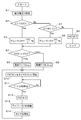
- FIG. 4 is a control flowchart of the power supply device 1.
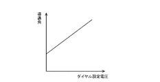
- FIG. 4 is a graph showing the relationship between the operation amount (set voltage) of the speed setting dial 22 and the conduction angle of the triac 26 in the electric tool 2.
- the wave form diagram which shows an example of the 50Hz sine wave (commercial alternating voltage), the output voltage of the power supply device 1, and the zero cross detection signal of the electric tool 2.
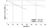
- FIG. An example of the relationship between the total output voltage of the battery packs 10 connected in series and the ON time of the switching element 14 per cycle when the cycle of the output voltage of the power supply device 10 is 10 ms (set frequency is 50 Hz). Graph showing.
- the power supply device 1 of the present embodiment has a plurality of (three in the illustrated example) battery pack mounting portions 7 on the upper surface of the housing 5.
- the battery pack 10 can be detachably mounted on each battery pack mounting portion 7.
- a power switch 6, a plug insertion port 8 as an output terminal, and a 50 Hz / 60 Hz changeover switch 9 as frequency switching means are provided on the right side of the housing 5.
- the power switch 6 is a switch for the user to switch between driving and stopping of the power supply device 1.
- the plug insertion port 8 is a part into which the plug of the power cord 3 (FIG. 3) is inserted. As shown in FIG.
- the electric tool 2 is a grinder.
- the 50 Hz / 60 Hz switch 9 is a switch for the user to switch the frequency of the output voltage of the power supply device 1.
- a control system power supply 11 a voltage measurement circuit 12, a control unit 13 such as a microcomputer, and a switching element 14 such as an FET as shown in FIG.
- each battery pack 10 has a configuration in which, for example, 10 3.6V secondary battery cells are connected in series, and the rated output voltage is 36V.
- the power supply device 1 has a configuration in which 30 secondary battery cells are connected in series. Note that, at both ends of the three battery packs 10 connected in series, a maximum voltage of 120 V appears depending on the remaining capacity of each battery pack 10.
- the power switch 6 is provided in a discharge path that connects the positive side of the battery pack 10 connected in series to the positive terminal of the plug insertion port 8.
- the control system power supply 11 Based on the output voltage of the battery pack 10 (the voltage on the output side of the power switch 6), the control system power supply 11 generates, for example, a DC voltage of 5V that is the operating voltage of the control unit 13.
- the voltage measurement circuit 12 measures the output voltage of each battery pack 10 and the voltage on the output side of the power switch 6, and transmits the result to the control unit 13.
- the control unit 13 controls on / off of the switching element 14 as described later (for example, PWM control).
- the switching element 14 is provided in a discharge path that connects from the negative side of the series connection of the battery pack 10 to the negative terminal of the plug insertion port 8.
- the electric power tool 2 shown in FIGS. 3 and 5 is an example of an electric device that operates in a phase control system, and the rotation speed of the motor 28 is adjusted by controlling the conduction angle of the triac 26 connected in series to the motor 28. Is possible.
- the electric power tool 2 switches between driving and stopping of the motor 28 (whether or not power is supplied to the motor 28) by operating the trigger switch 25.
- a photocoupler 24 is provided to detect zero crossing.
- the photocoupler 24 includes a pair of light-emitting diodes D1 and D2 and a phototransistor Tr1, and both the light-emitting diodes D1 and D2 stop emitting light during a period in which the input voltage via the trigger switch 25 is close to zero.
- Tr1 is turned off, a zero cross detection signal that is at a high level only during this period is transmitted to the control unit 23.
- the control system power supply 21 generates an operating voltage VDD (for example, a DC voltage of 5 V) of the control unit 23 based on the input voltage that has passed through the trigger switch 25.
- the speed setting dial 22 is an example of speed setting means, and is provided for the user to set the rotation speed of the motor 28.
- the control unit 23 controls on / off of the switching element 27 and controls the conduction angle of the triac 26 based on the zero cross detection signal from the photocoupler 24 and the speed setting value (speed setting voltage) by the speed setting dial 22.
- FIG. 6 is a control flowchart of the power supply device 1. This flowchart starts when the user turns on the power switch 6 in a state in which the battery packs 10 are mounted on all the battery pack mounting portions 7 of the power supply device 1.
- the control unit 13 detects the voltage V on the output side of the power switch 6 (the output voltage V of the battery packs 10 connected in series) from the output signal of the voltage measurement circuit 12 (S1). If the detected voltage V exceeds 100 V (S2, Yes), the control unit 13 sets the duty ratio D of the on / off control (PWM control) of the switching element 14 to 100 / V [%] (S3). This means that the target effective value of the output voltage of the power supply device 1 is set to 100V.
- the control unit 13 sets the duty ratio D to 80 / V [%] (S5). This means that the target effective value of the output voltage of the power supply device 1 is set to 80V. If the detected voltage V is 80 V or less, the control unit 13 turns off the switching element 14 (S6) and does not perform voltage output from the plug insertion port 8. This considers the possibility that the AC-driven electric device cannot be operated normally unless the output voltage is less than 80V.
- the control unit 13 turns on the switching element 14 and starts a timer count (S10).
- the control unit 13 maintains the switching element 14 in the on state until T ⁇ D seconds elapse after the switching element 14 is turned on (No in S11), and T ⁇ D seconds has elapsed after the switching element 14 is turned on.
- the switching element 14 is turned off (S12).
- the control unit 13 maintains the switching element 14 in the OFF state, waits for T ⁇ (1-D) seconds (S13), initializes the timer (S14), and returns to step S10. By repeating the operations in steps S10 to S14, an output voltage appears at the plug insertion port 8 of the power supply device 1.
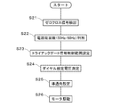
- FIG. 7 is a control flowchart of the electric power tool 2.
- the control unit 23 detects the zero cross detection signal from the photocoupler 24 (S21), and determines the frequency (50 Hz / 60 Hz) of the output voltage of the power supply device 1 input via the trigger switch 25 (S22).
- the control unit 23 sets the control range of the gate signal of the triac 26 according to the determined frequency (S23).
- the control unit 23 measures the speed setting voltage by the speed setting dial 22 (S24), and sets the conduction angle of the triac 26 based on the speed setting voltage (S25).
- An example of the relationship between the speed setting voltage (dial setting voltage) and the conduction angle is shown in FIG.
- the conduction angle setting process may be performed prior to or in parallel with the setting process of the control range of the gate signal of the triac 26.
- the control unit 23 controls on / off of the switching element 27 (that is, on / off of the triac 26) based on the control range set in step S23 and the conduction angle set in step S25 to energize the motor 28, and the motor 28 is driven at a constant speed.
- Control (S26) is performed prior to or in parallel with the setting process of the control range of the gate signal of the triac 26.
- FIG. 9 is a waveform diagram showing an example of a 50 Hz sine wave (commercial AC voltage), an output voltage of the power supply device 1, and a zero cross detection signal of the electric tool 2.
- the output voltage of the power supply device 1 temporarily becomes zero at the same cycle as the zero-cross generation cycle of the sine wave of the set frequency (50 Hz in the illustrated example) by the control shown in FIG. 6.
- the effective value is controlled to 100 V or 80 V (100 V in the illustrated example) according to the voltage on the output side of the power switch 6.
- the photocoupler 24 In the electric power tool 2, the photocoupler 24 generates a zero cross detection signal during a period in which the output voltage of the power supply device 1 is temporarily zero.
- the 10 shows the total output voltage of the battery packs 10 connected in series and the ON time of the switching element 14 per cycle when the cycle of the output voltage of the power supply device 10 is 10 ms (set frequency is 50 Hz). It is a graph which shows an example of a relationship.
- the range from 100V to 120V is the first voltage range
- the range from 80V to 100V is the second voltage range
- the target effective value of the output voltage is 100V in the first voltage range
- the target effective value of the output voltage is 80V.
- the target effective value is switched by changing the temporary OFF time of the switching element 14 per cycle, that is, the duty ratio D of the ON / OFF control of the switching element 14.
- the temporary off time of the switching element 14 per cycle is increased.
- the effective value of the output voltage of the power supply device 1 is controlled to be constant even if the total output voltage of the battery pack 10 changes.
- the control unit 13 causes the switching element 14 provided in the discharge path connected from the battery pack 10 to the plug insertion port 8 to have a predetermined cycle, that is, a cycle (100 Hz or 120 Hz) twice that of the commercial power source.
- a cycle 100 Hz or 120 Hz
- an electric device such as the electric tool 2 that operates at the output voltage of the power supply device 1 can detect a pseudo zero cross at the timing when the switching element 14 is turned off, and phase control using the zero cross or the like can be performed. Predetermined control is possible. Therefore, the power supply device 1 can supply power to an electrical device that detects zero crossing and performs predetermined control.
- the saddle control unit 13 adjusts the temporary off time of the switching element 14 per cycle, that is, the duty ratio D of the on / off control of the switching element 14, so that the total output voltage of the battery pack 10 exceeds 100V Even in this case, since the effective value of the output voltage from the power supply device 1 is controlled to 100 V or less, it is possible to suppress the output of a voltage having an effective value larger than AC 100 V, and an electric device such as the electric power tool 2 serving as a power supply destination It can suppress that it does not operate
- the bag control unit 13 includes each of the case where the total output voltage of the battery pack 10 is in the first voltage range exceeding 100V and up to 120V, and the case where the total output voltage is in the second voltage range exceeding 80V and up to 100V.
- the temporary off time of the switching element 14 per cycle that is, the duty ratio D of the on / off control of the switching element 14 is adjusted according to the total output voltage of the battery pack 10, and the effective value of the output voltage of the power supply device 1 is adjusted. Since it is controlled to be constant, it is possible to suppress a change in the feeling of use of the electric device such as the power tool 2 as a power supply destination due to a change in the total output voltage of the battery pack 10 due to a change in the remaining capacity of the battery pack 10. .
- the battery control unit 13 sets the target effective value of the output voltage of the power supply device 1 to 100 V when the total output voltage of the battery pack 10 exceeds 100 V, while the target when the total output voltage of the battery pack 10 becomes 100 V or less. Since the effective value is switched to 80V, even if the total output voltage of the battery pack 10 is reduced to 100V or less, the power supply can be continued with the output voltage of the effective value 80V at which many AC-driven electric devices operate normally.
- the electric tool 2 such as a grinder is exemplified as the electric device that operates in the phase control method, but the electric device is not limited to the electric tool, and other devices such as a lighting dimmer, a heat source temperature controller, and the like. It may be of the kind.
- the specific numbers shown in the embodiment, such as the ON / OFF cycle of the switching element 14 and the duty ratio, the number of battery packs 10 and the total output voltage, and the target effective value of the output voltage of the power supply device 1 are merely examples, and are required. It may be set as appropriate according to the specifications.
- SYMBOLS 1 Power supply device, 2 ... Electric tool (electric equipment), 3 ... Power cord, 5 ... Housing, 6 ... Power switch, 7 ... Battery pack mounting part, 8 ... Plug insertion port (output terminal), 9 ... 50Hz / 60 Hz selector switch (frequency switching means), 10 ... battery pack, 11 ... control system power supply, 12 ... voltage measurement circuit, 13 ... control unit, 14 ... switching element, 21 ... control system power supply, 22 ... speed setting dial, 23 ... Control unit, 24 ... photocoupler (zero cross detection means), 25 ... trigger switch, 26 ... triac (switching element), 27 ... switching element, 28 ... motor
Landscapes
- Engineering & Computer Science (AREA)
- Manufacturing & Machinery (AREA)
- Chemical & Material Sciences (AREA)
- Chemical Kinetics & Catalysis (AREA)
- Electrochemistry (AREA)
- General Chemical & Material Sciences (AREA)
- Power Engineering (AREA)
- Microelectronics & Electronic Packaging (AREA)
- Charge And Discharge Circuits For Batteries Or The Like (AREA)
- Secondary Cells (AREA)
- Power Conversion In General (AREA)
Abstract
ゼロクロスを検出して所定の制御を行う電気機器への電源供給が可能な電源装置及び当該電源装置から電源力供給を受けて動作する電気機器を提供するため、電源装置1は、電池パック10と、電池パック10の電圧を出力するプラグ差込口8と、電池パック10からプラグ差込口8に繋がる放電経路に設けられたスイッチング素子14と、スイッチング素子14を制御する制御部13と、を備え、制御部13は、スイッチング素子14を、商用電源の2倍の周期で一時的にオフする。
Description
本発明は、電池セルの電圧を利用して電気機器に電源供給する電源装置、及び電源装置から電源力供給を受けて動作する電気機器に関する。
従来から、二次電池セルを内蔵した電池パックの電力によって駆動する電動工具が知られている。下記特許文献1には複数の電池パック(電池ユニット)の接続方式を切り替え可能とし、複数の電池パック(例えば18V)を直列に接続することで36Vの直流電圧を得ることが記載されている。また、下記特許文献2には、10個の電池セルを直列接続したセル組を4セット直列に接続することが記載されている。リチウムイオン電池セルの場合には、3.6V/セル×10セル×4セット=144Vの直流電圧を得ることができる。このように、所定数以上の電池パック(電池ユニット)を直列接続すれば、商用電源(例えばAC100V)で駆動する電気機器の電源として使用することも可能である。
特許文献1及び2に記載の電源装置から出力される電圧は直流のため、商用電源で駆動する電気機器を接続して使用する場合、使用できる電気機器に制限があった。例えば、グラインダ等の、交流入力電圧のゼロクロスを検出して所定の制御(例えば位相制御)を行う電動工具には使用できなかった。
本発明はこうした状況を認識してなされたものであり、その目的は、ゼロクロスを検出して所定の制御を行う電気機器への電源供給が可能な電源装置及び当該電源装置から電源力供給を受けて動作する電気機器を提供することにある。
本発明のある態様は、電源装置である。この電源装置は、電池セルと、前記電池セルに電気的に接続された出力端子と、前記電池セルから前記出力端子に繋がる放電経路に設けられたスイッチング素子と、前記スイッチング素子を制御する制御部と、を備え、前記制御部は、前記スイッチング素子を、商用電源の2倍の周期で一時的にオフすることを特徴とする。
前記周期が100Hz又は120Hzであってもよい。
前記制御部は、前記周期を100Hzと120Hzとの間で切替可能であってもよい。
前記制御部は、前記電池セルの電圧に応じて、前記スイッチング素子の一時的なオフ時間、又は前記スイッチング素子のオンオフ制御のデューティ比を変更してもよい。
前記制御部は、所定電圧範囲内において、前記電池セルの電圧が高い場合に、前記電圧が低い場合よりも、前記オフ時間を長くする、又は前記デューティ比を小さくしてもよい。
前記制御部は、前記オフ時間又は前記デューティ比の調整により、前記電池セルの電圧が所定値以上の第1電圧範囲にある場合と、前記所定値未満の第2電圧範囲にある場合との間で、本電源装置の出力電圧の実効値を切り替えてもよい。
本発明のもう1つの態様は、位相制御方式で動作する電気機器を駆動可能な電源装置であって、商用電源の2倍の周期で出力を一時的に停止することを特徴とする。
前記周期が100Hz又は120Hzであってもよい。
前記周期を100Hzと120Hzとの間で切替可能であってもよい。
本発明のもう1つの態様は、前記電源装置から電力供給を受けて動作することを特徴とする電気機器である。
モータを備え、位相制御方式で前記モータを駆動してもよい。
なお、以上の構成要素の任意の組合せ、本発明の表現を方法やシステムなどの間で変換したものもまた、本発明の態様として有効である。
本発明によれば、ゼロクロスを検出して所定の制御を行う電気機器への電源供給が可能な電源装置及び当該電源装置から電源力供給を受けて動作する電気機器を提供することができる。
以下、図面を参照しながら本発明の好適な実施の形態を詳述する。なお、各図面に示される同一または同等の構成要素、部材、処理等には同一の符号を付し、適宜重複した説明は省略する。また、実施の形態は発明を限定するものではなく例示であり、実施の形態に記述されるすべての特徴やその組み合わせは必ずしも発明の本質的なものであるとは限らない。
図1(A)~図1(C)に示すように、本実施の形態の電源装置1は、ハウジング5の上面に複数の(図示の例では3つの)電池パック装着部7を有する。各々の電池パック装着部7には、図2(A)~図2(C)に示すように、電池パック10を着脱可能に装着できる。ハウジング5の右側面には、電源スイッチ6、出力端子としてのプラグ差込口8、及び周波数切替手段としての50Hz/60Hz切替スイッチ9が設けられる。電源スイッチ6は、ユーザが電源装置1の駆動、停止を切り替えるためのスイッチである。プラグ差込口8は、電源コード3(図3)のプラグを差し込む部分である。図3に示すように、プラグ差込口8に接続した電源コード3により、電源装置1から電動工具2に電源を供給できる。なお、図3に示す例では電動工具2はグラインダである。50Hz/60Hz切替スイッチ9は、ユーザが電源装置1の出力電圧の周波数を切り替えるためのスイッチである。ハウジング5の内部には、図4に示す制御系電源11、電圧測定回路12、マイコン等の制御部13、及びFET等のスイッチング素子14が設けられる。
図4に示すように、電源装置1において、3つの電池パック10は直列接続される。各電池パック10は、例えば、3.6Vの二次電池セルを10本直列接続した構成であり、定格出力電圧が36Vである。この場合、電源装置1は、30本の二次電池セルを直列接続した構成となる。なお、直列接続された3つの電池パック10の両端には、各電池パック10の残容量に応じて、最大120Vの電圧が現れる。
電源スイッチ6は、電池パック10の直列接続のプラス側からプラグ差込口8のプラス端子に繋がる放電経路に設けられる。制御系電源11は、電池パック10の出力電圧(電源スイッチ6の出力側の電圧)を基に、制御部13の動作電圧となる例えば5Vの直流電圧を生成する。電圧測定回路12は、各電池パック10の出力電圧、及び電源スイッチ6の出力側の電圧を測定し、結果を制御部13に送信する。制御部13は、50Hz/60Hz切替スイッチ9によって設定された周波数、及び電圧測定回路12によって測定された電池パック10の出力電圧を基に、後述のように、スイッチング素子14のオンオフを制御(例えばPWM制御)する。スイッチング素子14は、電池パック10の直列接続のマイナス側からプラグ差込口8のマイナス端子に繋がる放電経路に設けられる。
図3及び図5に示す電動工具2は、位相制御方式で動作する電気機器の例示であり、モータ28に直列接続されたトライアック26の導通角を制御することで、モータ28の回転速度を調節可能である。図5に示すように、電動工具2は、トリガスイッチ25の操作によりモータ28の駆動、停止(モータ28への電力供給の有無)を切り替えるものであって、トリガスイッチ25を経由した入力電圧のゼロクロスを検出するためにフォトカプラ24を有する。フォトカプラ24は、一対の発光ダイオードD1、D2と、フォトトランジスタTr1とを含み、トリガスイッチ25を経由した入力電圧が0近傍となる期間に双方の発光ダイオードD1、D2が発光を停止しフォトトランジスタTr1がオフとなることで、当該期間のみハイレベルとなるゼロクロス検出信号を制御部23に送信する。
制御系電源21は、トリガスイッチ25を経由した入力電圧を基に、制御部23の動作電圧VDD(例えば5Vの直流電圧)を生成する。速度設定ダイヤル22は、速度設定手段の例示であり、ユーザがモータ28の回転速度を設定するために設けられる。制御部23は、フォトカプラ24からのゼロクロス検出信号、及び速度設定ダイヤル22による速度設定値(速度設定電圧)を基に、スイッチング素子27のオンオフを制御し、トライアック26の導通角を制御する。
図6は、電源装置1の制御フローチャートである。このフローチャートは、電源装置1の全ての電池パック装着部7にそれぞれ電池パック10が装着された状態で、ユーザが電源スイッチ6をオンにすることによってスタートする。制御部13は、電圧測定回路12の出力信号により、電源スイッチ6の出力側の電圧V(直列接続された電池パック10の出力電圧V)を検出する(S1)。制御部13は、検出した電圧Vが100Vを超えていれば(S2、Yes)、スイッチング素子14のオンオフ制御(PWM制御)のデューティ比Dを100/V[%]に設定する(S3)。これは、電源装置1の出力電圧の目標実効値を100Vに設定したことを意味する。制御部13は、検出した電圧Vが100V以下(S2、No)かつ80Vを超えていれば(S4、Yes)、デューティ比Dを80/V[%]に設定する(S5)。これは、電源装置1の出力電圧の目標実効値を80Vに設定したことを意味する。制御部13は、検出した電圧Vが80V以下であれば、スイッチング素子14をオフし(S6)、プラグ差込口8からの電圧出力を行わない。これは、出力電圧が80Vに満たないとAC駆動の電気機器を正常に動作させられない可能性を考慮したものである。
続いて制御部13は、50Hz/60Hz切替スイッチ9による設定周波数を確認し(S7)、設定周波数が50Hzであれば(S7、Yes)、スイッチング素子14のオンオフ制御(PWM制御)の周期Tを10msに設定し(S8)、設定周波数が60Hzであれば(S7、No)、周期Tを8.3ms(=1,000ms/120)に設定する(S9)。これは、50Hzの正弦波ではゼロクロスが100Hzの周波数(10msの周期)で発生し、60Hzの正弦波ではゼロクロスが120Hzの周波数(8.3msの周期)で発生することに合わせた設定である。なお、周期Tの設定に関する処理を、ディーティ比Dの設定に関する処理より先に又は当該処理と並列に行ってもよい。
デューティ比D及び周期Tの設定が完了すると、制御部13は、スイッチング素子14をオンすると共にタイマカウントを開始する(S10)。制御部13は、スイッチング素子14をオンしてからT×D秒が経過するまではスイッチング素子14をオン状態に維持し(S11、No)、スイッチング素子14をオンしてからT×D秒が経過すると(S11、Yes)、スイッチング素子14をオフする(S12)。制御部13は、スイッチング素子14をオフ状態に維持してT×(1-D)秒待機し(S13)、タイマを初期化し(S14)、ステップS10に戻る。ステップS10~S14の動作を繰り返すことで、電源装置1のプラグ差込口8に出力電圧が現れる。
図7は、電動工具2の制御フローチャートである。制御部23は、フォトカプラ24からのゼロクロス検出信号を検出し(S21)、トリガスイッチ25を経由して入力された電源装置1の出力電圧の周波数(50Hz/60Hz)を判別する(S22)。制御部23は、判別した周波数に応じてトライアック26のゲート信号の制御範囲を設定する(S23)。一方、制御部23は、速度設定ダイヤル22による速度設定電圧を測定し(S24)、速度設定電圧を基にトライアック26の導通角を設定する(S25)。速度設定電圧(ダイヤル設定電圧)と導通角の関係の一例を図8に示す。なお、導通角設定処理を、トライアック26のゲート信号の制御範囲の設定処理より先に又は当該処理と並列に行ってもよい。制御部23は、ステップS23で設定した制御範囲とステップS25で設定した導通角を基にスイッチング素子27のオンオフ(すなわちトライアック26のオンオフ)を制御してモータ28に通電し、モータ28を定速度制御する(S26)。
図9は、50Hz正弦波(商用交流電圧)、電源装置1の出力電圧、及び電動工具2のゼロクロス検出信号の一例を示す波形図である。図9に示すように、電源装置1の出力電圧は、図6に示す制御により、設定された周波数(図示の例では50Hz)の正弦波のゼロクロス発生周期と同じ周期で一時的にゼロになり、また実効値は電源スイッチ6の出力側の電圧に応じて100V又は80V(図示の例では100V)に制御される。そして電動工具2においては、電源装置1の出力電圧が一時的にゼロになっている期間にフォトカプラ24がゼロクロス検出信号を発生する。
図10は、電源装置1の出力電圧の周期が10ms(設定周波数が50Hz)の場合における、直列接続された電池パック10の合計出力電圧と、1周期あたりのスイッチング素子14のオン時間と、の関係の一例を示すグラフである。電源装置1では、100Vを超えて120Vまでの範囲を第1電圧範囲とし、80Vを超えて100Vまでの範囲を第2電圧範囲とし、第1電圧範囲では出力電圧の目標実効値を100Vとし、第2電圧範囲では出力電圧の目標実効値を80Vとする。目標実効値の切替は、1周期あたりのスイッチング素子14の一時的なオフ時間、すなわちスイッチング素子14のオンオフ制御のデューティ比Dを変更することで行われる。また、第1及び第2電圧範囲の各々において、直列接続された電池パック10の合計出力電圧が高くなるほど、1周期あたりのスイッチング素子14の一時的なオフ時間を長くする、すなわちスイッチング素子14のオンオフ制御のデューティ比Dを小さくすることで、電池パック10の合計出力電圧が変化しても電源装置1の出力電圧の実効値が一定に制御される。
本実施の形態によれば、下記の効果を奏することができる。
(1) 電源装置1において制御部13は、電池パック10からプラグ差込口8に繋がる放電経路に設けられたスイッチング素子14を所定周期、すなわち商用電源の2倍の周期(100Hz又は120Hz)で一時的にオフするため、電源装置1の出力電圧で動作する電動工具2等の電気機器は、スイッチング素子14がオフになるタイミングで擬似的にゼロクロスを検出でき、ゼロクロスを利用した位相制御等の所定の制御が可能となる。したがって、電源装置1により、ゼロクロスを検出して所定の制御を行う電気機器への電源供給が可能となる。
(2) 制御部13は、1周期あたりのスイッチング素子14の一時的なオフ時間、すなわちスイッチング素子14のオンオフ制御のデューティ比Dを調整することで、電池パック10の合計出力電圧が100Vを超える場合でも電源装置1からの出力電圧の実効値を100V以下に制御するため、AC100Vよりも大きな実効値の電圧が出力されることを抑制でき、電源供給先となる電動工具2等の電気機器が正常に動作しなかったり、電気機器内部の回路部品が破損したりすることを抑制できる。
(3) 制御部13は、電池パック10の合計出力電圧が100Vを超えて120Vまでの第1電圧範囲にある場合と、80Vを超えて100Vまでの第2電圧範囲にある場合と、の各々において、電池パック10の合計出力電圧に応じて1周期あたりのスイッチング素子14の一時的なオフ時間すなわちスイッチング素子14のオンオフ制御のデューティ比Dを調整し、電源装置1の出力電圧の実効値を一定に制御するため、電池パック10の残容量の変化による電池パック10の合計出力電圧の変化に起因して電源供給先となる電動工具2等の電気機器の使用感が変化することを抑制できる。
(4) 制御部13は、電池パック10の合計出力電圧が100Vを超える場合は電源装置1の出力電圧の目標実効値を100Vにする一方、電池パック10の合計出力電圧が100V以下になると目標実効値を80Vに切り替えるため、電池パック10の合計出力電圧が100V以下に低下しても、交流駆動の電気機器の多くが正常に動作する実効値80Vの出力電圧により電源供給を継続できる。
以上、実施の形態を例に本発明を説明したが、実施の形態の各構成要素や各処理プロセスには請求項に記載の範囲で種々の変形が可能であることは当業者に理解されるところである。以下、変形例について触れる。
実施の形態では、位相制御方式で動作する電気機器としてグラインダ等の電動工具2を例示したが、電気機器は、電動工具に限定されず、照明の調光器や熱源の温度調整器等の他の種類のものであってもよい。スイッチング素子14のオンオフの周期やデューティ比、電池パック10の個数や合計出力電圧、電源装置1の出力電圧の目標実効値等、実施の形態で示した具体的な数字は一例に過ぎず、要求される仕様に合わせて適宜設定すればよい。
1…電源装置、2…電動工具(電気機器)、3…電源コード、5…ハウジング、6…電源スイッチ、7…電池パック装着部、8…プラグ差込口(出力端子)、9…50Hz/60Hz切替スイッチ(周波数切替手段)、10…電池パック、11…制御系電源、12…電圧測定回路、13…制御部、14…スイッチング素子、21…制御系電源、22…速度設定ダイヤル、23…制御部、24…フォトカプラ(ゼロクロス検出手段)、25…トリガスイッチ、26…トライアック(スイッチング素子)、27…スイッチング素子、28…モータ
Claims (11)
- 電池セルと、
前記電池セルに電気的に接続された出力端子と、
前記電池セルから前記出力端子に繋がる放電経路に設けられたスイッチング素子と、
前記スイッチング素子を制御する制御部と、を備え、
前記制御部は、前記スイッチング素子を、商用電源の2倍の周期で一時的にオフすることを特徴とする、電源装置。 - 前記周期が100Hz又は120Hzであることを特徴とする、請求項1に記載の電源装置。
- 前記制御部は、前記周期を100Hzと120Hzとの間で切替可能であることを特徴とする、請求項1に記載の電源装置。
- 前記制御部は、前記電池セルの電圧に応じて、前記スイッチング素子の一時的なオフ時間、又は前記スイッチング素子のオンオフ制御のデューティ比を変更することを特徴とする、請求項1から3のいずれか一項に記載の電源装置。
- 前記制御部は、所定電圧範囲内において、前記電池セルの電圧が高い場合に、前記電圧が低い場合よりも、前記オフ時間を長くする、又は前記デューティ比を小さくすることを特徴とする、請求項4に記載の電源装置。
- 前記制御部は、前記オフ時間又は前記デューティ比の調整により、前記電池セルの電圧が所定値以上の第1電圧範囲にある場合と、前記所定値未満の第2電圧範囲にある場合との間で、本電源装置の出力電圧の実効値を切り替えることを特徴とする、請求項4又は5に記載の電源装置。
- 位相制御方式で動作する電気機器を駆動可能な電源装置であって、
商用電源の2倍の周期で出力を一時的に停止することを特徴とする、電源装置。 - 前記周期が100Hz又は120Hzであることを特徴とする、請求項7に記載の電源装置。
- 前記周期を100Hzと120Hzとの間で切替可能であることを特徴とする、請求項8に記載の電源装置。
- 請求項1から9のいずれか一項に記載の電源装置から電力供給を受けて動作することを特徴とする、電気機器。
- モータを備え、位相制御方式で前記モータを駆動することを特徴とする、請求項10に記載の電気機器。
Priority Applications (4)
| Application Number | Priority Date | Filing Date | Title |
|---|---|---|---|
| US16/096,303 US20190140567A1 (en) | 2016-04-28 | 2017-03-31 | Power supply device and electric device |
| DE212017000119.4U DE212017000119U1 (de) | 2016-04-28 | 2017-03-31 | Stromversorgungsvorrichtung und elektrisches Gerät |
| CN201790000799.1U CN209462248U (zh) | 2016-04-28 | 2017-03-31 | 电源装置及电气设备 |
| JP2018514219A JP6743886B2 (ja) | 2016-04-28 | 2017-03-31 | 電源装置及び電気機器 |
Applications Claiming Priority (2)
| Application Number | Priority Date | Filing Date | Title |
|---|---|---|---|
| JP2016-090275 | 2016-04-28 | ||
| JP2016090275 | 2016-04-28 |
Publications (1)
| Publication Number | Publication Date |
|---|---|
| WO2017187891A1 true WO2017187891A1 (ja) | 2017-11-02 |
Family
ID=60160389
Family Applications (1)
| Application Number | Title | Priority Date | Filing Date |
|---|---|---|---|
| PCT/JP2017/013669 Ceased WO2017187891A1 (ja) | 2016-04-28 | 2017-03-31 | 電源装置及び電気機器 |
Country Status (5)
| Country | Link |
|---|---|
| US (1) | US20190140567A1 (ja) |
| JP (1) | JP6743886B2 (ja) |
| CN (1) | CN209462248U (ja) |
| DE (1) | DE212017000119U1 (ja) |
| WO (1) | WO2017187891A1 (ja) |
Cited By (2)
| Publication number | Priority date | Publication date | Assignee | Title |
|---|---|---|---|---|
| CN111443291A (zh) * | 2019-01-16 | 2020-07-24 | 罗伯特·博世有限公司 | 用于对运行方法进行测试的方法和设备 |
| JP2023023030A (ja) * | 2021-08-04 | 2023-02-16 | マックス株式会社 | 電源装置 |
Citations (3)
| Publication number | Priority date | Publication date | Assignee | Title |
|---|---|---|---|---|
| JP2006060009A (ja) * | 2004-08-20 | 2006-03-02 | Shinko Electric Co Ltd | 発光ダイオード駆動回路 |
| JP2012095457A (ja) * | 2010-10-27 | 2012-05-17 | Hitachi Koki Co Ltd | 電源装置及びその電源装置を備えた電動工具 |
| WO2014148228A1 (ja) * | 2013-03-22 | 2014-09-25 | 日立工機株式会社 | 電池パック及び電気機器 |
Family Cites Families (7)
| Publication number | Priority date | Publication date | Assignee | Title |
|---|---|---|---|---|
| JP3982247B2 (ja) * | 2001-12-06 | 2007-09-26 | 株式会社デンソー | 車両用発電機の制御装置 |
| JP3705490B2 (ja) * | 2002-02-14 | 2005-10-12 | 矢崎総業株式会社 | 負荷駆動装置 |
| JP2011079510A (ja) * | 2009-09-10 | 2011-04-21 | Makita Corp | 電動車 |
| US20120228041A1 (en) * | 2009-11-13 | 2012-09-13 | Positec Power Tools (Suzhou) Co., Ltd. | Lawn mower |
| CN105170526A (zh) * | 2011-07-26 | 2015-12-23 | 苏州宝时得电动工具有限公司 | 便携式清洗设备 |
| JP6073901B2 (ja) * | 2012-09-05 | 2017-02-01 | 三洋電機株式会社 | 車両用のバッテリシステムとこれを搭載する車両 |
| JP6450084B2 (ja) * | 2014-04-08 | 2019-01-09 | 株式会社マキタ | 電動工具及びその販売システム |
-
2017
- 2017-03-31 US US16/096,303 patent/US20190140567A1/en not_active Abandoned
- 2017-03-31 WO PCT/JP2017/013669 patent/WO2017187891A1/ja not_active Ceased
- 2017-03-31 JP JP2018514219A patent/JP6743886B2/ja not_active Expired - Fee Related
- 2017-03-31 CN CN201790000799.1U patent/CN209462248U/zh not_active Expired - Fee Related
- 2017-03-31 DE DE212017000119.4U patent/DE212017000119U1/de not_active Expired - Lifetime
Patent Citations (3)
| Publication number | Priority date | Publication date | Assignee | Title |
|---|---|---|---|---|
| JP2006060009A (ja) * | 2004-08-20 | 2006-03-02 | Shinko Electric Co Ltd | 発光ダイオード駆動回路 |
| JP2012095457A (ja) * | 2010-10-27 | 2012-05-17 | Hitachi Koki Co Ltd | 電源装置及びその電源装置を備えた電動工具 |
| WO2014148228A1 (ja) * | 2013-03-22 | 2014-09-25 | 日立工機株式会社 | 電池パック及び電気機器 |
Cited By (3)
| Publication number | Priority date | Publication date | Assignee | Title |
|---|---|---|---|---|
| CN111443291A (zh) * | 2019-01-16 | 2020-07-24 | 罗伯特·博世有限公司 | 用于对运行方法进行测试的方法和设备 |
| JP2023023030A (ja) * | 2021-08-04 | 2023-02-16 | マックス株式会社 | 電源装置 |
| JP7742034B2 (ja) | 2021-08-04 | 2025-09-19 | マックス株式会社 | 電源装置 |
Also Published As
| Publication number | Publication date |
|---|---|
| US20190140567A1 (en) | 2019-05-09 |
| JPWO2017187891A1 (ja) | 2018-12-27 |
| JP6743886B2 (ja) | 2020-08-19 |
| CN209462248U (zh) | 2019-10-01 |
| DE212017000119U1 (de) | 2018-11-30 |
Similar Documents
| Publication | Publication Date | Title |
|---|---|---|
| US10411558B2 (en) | Cycle-by-cycle current limit for a power tool having a brushless motor | |
| JP3759736B2 (ja) | モーター電源供給装置及びモーター電源供給方法 | |
| CN100423404C (zh) | 具有电池充电功能的dc电源单元 | |
| EP2696466B1 (en) | Adapter and electric power tool | |
| US8558518B2 (en) | Methods and apparatuses for phase-cut dimming at low conduction angles | |
| EP2736147B1 (en) | Operating a static transfer switch to eliminate transformer inrush current in the presence of residual flux | |
| EP3386096B1 (en) | Waveform shaping in power tool powered by alternating-current power supply | |
| CN102210091B (zh) | 被布置成控制施加到负载上的电压的电子电路 | |
| TWI399913B (zh) | 電源裝置 | |
| WO2006124278A3 (en) | Dimmer having a power supply monitoring circuit | |
| CN104104245A (zh) | 基于与负载的通信具有可选操作的电源 | |
| EP3146627B1 (en) | Cycle-by-cycle current limit for power tools having a brushless motor | |
| CN1040293A (zh) | 电力发生器 | |
| JP6681301B2 (ja) | 切替え装置 | |
| JP6743886B2 (ja) | 電源装置及び電気機器 | |
| JP5632613B2 (ja) | 電気モーターのパワー制御 | |
| US20120147628A1 (en) | Resonant circuit with constant current characteristics | |
| JP2014050234A (ja) | 電源装置 | |
| CN103190065A (zh) | 电源设备 | |
| JP3873648B2 (ja) | 充電機能付き直流電源装置 | |
| TW201919531A (zh) | 由蓄電池供電的家用電器以及操作家用電器之方法 | |
| CN105813880B (zh) | 用于使电机运行的设备和方法 | |
| KR100523817B1 (ko) | 유도 전동기용 회생 에너지 충전장치 | |
| JP5773180B2 (ja) | 負荷制御装置 | |
| KR19980036737A (ko) | 전기면도기의 전원장치 |
Legal Events
| Date | Code | Title | Description |
|---|---|---|---|
| WWE | Wipo information: entry into national phase |
Ref document number: 2018514219 Country of ref document: JP |
|
| 121 | Ep: the epo has been informed by wipo that ep was designated in this application |
Ref document number: 17789179 Country of ref document: EP Kind code of ref document: A1 |
|
| 122 | Ep: pct application non-entry in european phase |
Ref document number: 17789179 Country of ref document: EP Kind code of ref document: A1 |