WO2017187630A1 - タンク、ターゲット生成装置、及び、極端紫外光生成装置 - Google Patents
タンク、ターゲット生成装置、及び、極端紫外光生成装置 Download PDFInfo
- Publication number
- WO2017187630A1 WO2017187630A1 PCT/JP2016/063474 JP2016063474W WO2017187630A1 WO 2017187630 A1 WO2017187630 A1 WO 2017187630A1 JP 2016063474 W JP2016063474 W JP 2016063474W WO 2017187630 A1 WO2017187630 A1 WO 2017187630A1
- Authority
- WO
- WIPO (PCT)
- Prior art keywords
- opening
- support portion
- tank
- lid
- tank body
- Prior art date
- Legal status (The legal status is an assumption and is not a legal conclusion. Google has not performed a legal analysis and makes no representation as to the accuracy of the status listed.)
- Ceased
Links
Images








Classifications
-
- H—ELECTRICITY
- H05—ELECTRIC TECHNIQUES NOT OTHERWISE PROVIDED FOR
- H05G—X-RAY TECHNIQUE
- H05G2/00—Apparatus or processes specially adapted for producing X-rays, not involving X-ray tubes, e.g. involving generation of a plasma
- H05G2/001—Production of X-ray radiation generated from plasma
- H05G2/002—Supply of the plasma generating material
-
- G—PHYSICS
- G03—PHOTOGRAPHY; CINEMATOGRAPHY; ANALOGOUS TECHNIQUES USING WAVES OTHER THAN OPTICAL WAVES; ELECTROGRAPHY; HOLOGRAPHY
- G03F—PHOTOMECHANICAL PRODUCTION OF TEXTURED OR PATTERNED SURFACES, e.g. FOR PRINTING, FOR PROCESSING OF SEMICONDUCTOR DEVICES; MATERIALS THEREFOR; ORIGINALS THEREFOR; APPARATUS SPECIALLY ADAPTED THEREFOR
- G03F7/00—Photomechanical, e.g. photolithographic, production of textured or patterned surfaces, e.g. printing surfaces; Materials therefor, e.g. comprising photoresists; Apparatus specially adapted therefor
- G03F7/70—Microphotolithographic exposure; Apparatus therefor
- G03F7/70008—Production of exposure light, i.e. light sources
- G03F7/70033—Production of exposure light, i.e. light sources by plasma extreme ultraviolet [EUV] sources
Definitions
- the present disclosure relates to a tank, a target generation device, and an extreme ultraviolet light generation device.
- an LPP Laser Produced Plasma
- DPP discharge Produced Plasma
- a tank according to an aspect of the present disclosure includes a tank body having an opening therein and an opening that communicates with the space, a lid body that covers the opening of the tank body and a peripheral edge portion of the opening, and the tank body and the lid body at the peripheral edge portion.
- Bolts to be fixed a first support portion that surrounds the opening in a region closer to the opening than the bolt and supports the lid, and an opening in a region closer to the opening than the first support between the tank body and the lid
- a second support portion having a height lower than that of the first support portion, and an opening in a region on the opening side of the first support portion between the tank body and the lid.
- a sealing member is provided.
- a target generation device includes a tank main body having a space filled with a molten metal and having an opening communicating with the space, a cover that covers the opening of the tank main body and a peripheral edge of the opening, and a peripheral edge
- a second support portion that is disposed so as to surround the opening in a region closer to the opening than the first portion and has a height lower than the height of the first support portion, and is more open than the first support portion between the tank body and the lid.
- an extreme ultraviolet light generation device includes a tank body having a space filled with molten metal and having an opening communicating with the space, and a lid body that covers the opening of the tank body and a peripheral portion of the opening. And a bolt for fixing the tank body and the lid at the peripheral edge, a first support part that surrounds the opening in the region closer to the opening than the bolt and supports the lid, and between the tank body and the lid A second support portion disposed surrounding the opening in a region closer to the opening than the first support portion and having a height lower than the height of the first support portion; and the first support portion between the tank body and the lid body A sealing member that surrounds the opening in a region closer to the opening, a nozzle that is connected to the tank body and discharges a target made of molten metal in the space in the chamber, and a target that is output from the nozzle.
- FIG. 1 is a schematic diagram illustrating a schematic configuration example of an EUV light generation apparatus according to a comparative example.
- FIG. 2 is a diagram illustrating the target generation device of FIG.
- FIG. 3 is an enlarged view of a region surrounded by a broken line in FIG.
- FIG. 4 is a diagram illustrating the target generation device according to the first embodiment.
- FIG. 5 is an enlarged view of a region surrounded by a broken line in FIG.
- FIG. 6 is a diagram showing the color of FIG.
- FIG. 7 is a cross-sectional view of the collar taken along line VV in FIG.
- FIG. 8 is a diagram illustrating the target generation device according to the second embodiment.
- FIG. 1 is a schematic diagram illustrating a schematic configuration example of an EUV light generation apparatus according to a comparative example.
- FIG. 2 is a diagram illustrating the target generation device of FIG.
- FIG. 3 is an enlarged view of a region surrounded by a broken line in FIG.
- FIG. 9 is an enlarged view of a region surrounded by a broken line in FIG.
- FIG. 10 is a diagram illustrating the target generation device according to the third embodiment.
- FIG. 11 is an enlarged view of a region surrounded by a broken line in FIG.
- FIG. 12A is a diagram illustrating an example of a cross section of a gasket that can be used as a sealing member.
- FIG. 12B is a diagram illustrating an example of a cross section of another gasket that can be used as a sealing member.
- FIG. 12C is a diagram illustrating an example of a cross section of still another gasket that can be used as a sealing member.
- FIG. 12D is a view showing an example of a cross section of still another gasket that can be used as a sealing member.
- Embodiments of the present disclosure relate to a tank, a target generation device, and an extreme ultraviolet light generation device.
- the present invention relates to a tank, a target generation device, and an extreme ultraviolet light generation device that can suppress the occurrence of damage such as cracks in the tank.
- extreme ultraviolet light may be referred to as EUV light. Therefore, the extreme ultraviolet light generation device may be referred to as an EUV light generation device.
- FIG. 1 is a schematic diagram illustrating a schematic configuration example of an EUV light generation apparatus according to a comparative example.
- the EUV light generation apparatus 1 includes a chamber 2, a laser beam traveling direction controller 34, and a control unit 5.
- the EUV light generation apparatus 1 is normally used with a laser apparatus 3 added.
- the chamber 2 includes a target generation device 20, a laser condensing optical system 220, an EUV condensing mirror 23, a target recovery unit 28, and an exhaust device 210.
- the laser focusing optical system 220 includes a moving plate 221 on which the laser beam focusing mirror 22 and the high reflection mirror 222 are mounted, and a laser beam manipulator 223.
- the target generation device 20 is provided in a sub-chamber 201 connected to the chamber 2.
- the target generation device 20 includes a tank 40 and a nozzle 50.
- the tank 40 stores therein a target material 271 made of molten metal. Examples of the target material 271 include tin, terbium, gadolinium, lithium, xenon, or a combination of any two or more thereof.
- the nozzle 50 outputs the target material 271 as a droplet-like target 27.
- the inside of the tank 40 communicates with a pressure regulator 120 that adjusts the gas pressure via a pipe 121.
- the gas pressure inside the tank 40 may be referred to as tank internal pressure.
- the piezo element 111 is installed in the nozzle 50.
- the piezo element 111 is connected to the piezo power source 112, and the heater 141 is connected to the heater power source 143.
- the temperature sensor 142 and the heater 141 are arranged in the tank body.
- the piezo power source 112, the pressure regulator 120, the temperature sensor 142, and the heater power source 143 are each connected to the control unit 5.
- the laser beam traveling direction controller 34 includes an optical element for defining the traveling direction of the laser beam and an actuator for adjusting the position, posture, and the like of the optical element.
- a window 21 is provided on the wall of the chamber 2.
- the window 21 is output from the laser device 3, and a pulse laser beam 32 whose traveling direction is adjusted by a laser beam traveling direction controller 34 is transmitted therethrough.
- the laser condensing optical system 220 is arranged so that the pulsed laser light 32 emitted from the laser light traveling direction controller 34 is incident thereon.
- the laser beam manipulator 223 moves the moving plate 221 on which the laser beam focusing mirror 22 and the high reflection mirror 222 are fixed to the X axis so that the laser focusing position in the chamber 2 is a position designated by the control unit 5. , Move in the Y-axis and Z-axis directions.
- the EUV collector mirror 23 has first and second focal points. On the surface of the EUV collector mirror 23, for example, a multilayer reflective film in which molybdenum and silicon are alternately laminated is formed.
- the EUV collector mirror 23 is preferably arranged such that, for example, the first focal point thereof is located in the plasma generation region 25 and the second focal point thereof is located at the intermediate focal point (IF) 292.
- IF intermediate focal point
- a through hole 24 through which the pulse laser beam 33 passes is provided at the center of the EUV collector mirror 23.
- the EUV light generation apparatus 1 includes a control unit 5, a target sensor 4, and the like.
- the target sensor 4 has an imaging function and is configured to detect the presence, trajectory, position, speed, and the like of the target 27.
- the EUV light generation apparatus 1 includes a connection portion 29 that allows the inside of the chamber 2 and the inside of the exposure apparatus 6 to communicate with each other.
- a wall 291 in which an aperture 293 is formed is provided inside the connection portion 29.
- the wall 291 is preferably arranged so that its aperture 293 is located at the second focal position of the EUV collector mirror 23.
- the target collection unit 28 collects unnecessary targets 27.
- the EUV light generation apparatus 1 includes a hydrogen gas supply unit 301, a flow rate controller 302, a gas nozzle 303, and a gas pipe 304.
- the EUV light generation apparatus 1 further includes a pressure sensor 305.
- the hydrogen gas supply unit 301 is connected to a gas nozzle 303 via a gas pipe 304.
- the hydrogen gas supply unit 301 supplies, for example, a balance gas having a hydrogen gas concentration of about 3% to the gas pipe 304.
- the balance gas may contain nitrogen (N 2 ) gas or argon (Ar) gas.
- the gas nozzle 303 is provided in the sub-chamber 201 so that the blown-out hydrogen gas flows in the vicinity of the nozzle 50 of the target generation device 20.
- a flow rate regulator 302 is provided in a gas pipe 304 between the hydrogen gas supply unit 301 and the gas nozzle 303.
- the pressure sensor 305 For the pressure sensor 305, a cold cathode ionization gauge, a Pirani gauge, a capacitance manometer, or the like is used.
- the exhaust device 210 is used as a removal device that removes moisture in the chamber 2.
- the pressure sensor 305 and the flow rate regulator 302 are connected to the control unit 5.
- FIG. 2 is an enlarged view of the target generation device 20 of FIG.
- the heater 141, the temperature sensor 142, and the piezo element 111 described in FIG. 1 are omitted.
- the tank 40 includes a tank body 41 and a lid body 42.
- the tank body 41 is a cylindrical member having a space 41S inside and having an opening 41A communicating with the space 41S above, and is generally cylindrical in this example.
- the tank body 41 is preferably made of, for example, molybdenum, tantalum, or tungsten, which hardly reacts with tin.
- a peripheral edge portion 41R of the opening 41A which is an end portion of the tank main body 41, is a portion that supports the lid body 42.
- the lid body 42 is a plate-like member having a substantially flat bottom surface, and covers the opening 41A of the tank body 41 and the peripheral edge portion 41R of the opening 41A.
- the lid 42 covers the opening 41 ⁇ / b> A of the tank body 41 and the opening of the chamber 2.
- the lid body 42 is fixed to the tank body 41 by screwing a plurality of bolts 43 into the tank body 41 at the peripheral edge portion 41R.
- the number of bolts 43 is, for example, 16.
- the lid body 42 is made of, for example, stainless steel.
- bolt 43 consists of the same material as the cover body 42, for example, is formed from stainless steel.
- FIG. 3 is an enlarged view of a region surrounded by a broken line in FIG. 2, and shows a state where the lid body 42 is fixed on the peripheral edge portion 41 ⁇ / b> R of the tank main body 41 with bolts 43.
- a groove 41G for disposing a sealing member is provided in the peripheral portion 41R of the tank body 41 so as to surround the opening 41A on the opening 41A side of the bolt 43, that is, on the inner peripheral side of the bolt 43. Is formed.
- An inner O-ring 44 as a sealing member is disposed in the groove 41G over the entire circumference.
- the inner O-ring 44 is a tubular member formed in a ring shape.
- the inner O-ring 44 is made of a metal, for example, a tube-shaped stainless steel whose outer surface is silver-plated.
- the width 41Gw of the groove 41G is made larger than the diameter of the tube of the inner O-ring 44, and the depth of the groove 41G is made smaller than the diameter of the tube of the inner O-ring 44.
- the depth of the groove 41G is 1.25 mm, and the diameter of the inner O-ring tube is 1.6 mm. For this reason, when the lid 42 is not disposed, a part of the inner O-ring 44 disposed in the groove 41G protrudes upward from the groove 41G.
- the inner O-ring 44 is deformed so as to be crushed by the pressing force from the lid body 42 in a state where the lid body 42 is disposed on the peripheral edge portion 41R and the bolt 43 is tightened.
- the tank 40 is sealed inside the bolt 43 by filling a gap with the body 42.
- the silver plating is preferably deformed to fill a fine gap.
- the outer peripheral surface of the inner O-ring 44 is in contact with the outer wall of the groove 41G, and the inner O-ring 44 and the groove 41G are in contact with each other.
- a gap is formed between the inner wall and the inner wall.
- the inner O-ring 44 can generate a sufficient repulsive force.
- the thickness of the tube is, for example, 0.35 mm. Is done.
- a groove 41N for disposing a sealing member is formed in the peripheral edge portion 41R of the tank body 41 so as to surround the opening 41A on the side opposite to the opening 41A with respect to the bolt 43, that is, on the outer peripheral side of the bolt 43.
- An outer O-ring 45 as a sealing member is disposed in the groove 41N.
- the configuration of the outer O-ring 45 is the same as that of the inner O-ring 44 except for the diameter, for example.
- the depth of the groove 41N is the same as that of the groove 41G, for example. Accordingly, the outer O-ring 45 is deformed so as to be crushed in a state in which the lid body 42 is disposed and the bolt 43 is tightened, and the gap between the tank body 41 and the lid body 42 is filled. On the outside, the tank 40 is sealed.
- a through hole is formed in the approximate center of the lid body 42, and a pipe 121 communicates with the through hole to form a gas passage.
- the diameter of this gas passage is 8 mm, for example.
- the nozzle 50 is fixed to the tank body 41 with a plurality of bolts 51 below the tank body 41 as shown in FIG.
- a nozzle hole is formed in the nozzle 50, and the nozzle hole communicates with an opening below the tank body 41 so that the target material in the tank body 41 can be output from the nozzle hole.
- a groove 2 ⁇ / b> G for disposing a sealing member is formed in the peripheral portion 2 ⁇ / b> R in contact with the lid body 42 of the chamber 2.
- a chamber O-ring 204 as a sealing member is disposed over the entire circumference.
- the chamber O-ring 204 has the same shape as the inner O-ring 44 except for the diameter, and the material of the chamber O-ring 204 is made of the same material as the inner O-ring 44, for example. Or you may be comprised with resin.
- the chamber O-ring 204 is deformed so as to be crushed when the lid 42 is disposed on the peripheral edge 2R of the chamber 2 and the bolt 43 is tightened, so that the space between the chamber 2 and the lid 42 is reduced.
- the chamber 2 is sealed by filling the gap.
- the inside of the chamber 2 having the above configuration is generally evacuated, and a gas such as hydrogen remains slightly as will be described later. Further, an area not filled with the target material 271 in the space 41S in the tank 40 is filled with an inert gas such as argon.
- the pressure in the tank 40 is 40 MPa, for example. Since the inside of the tank 40 is set to a high pressure in this way, the inner O-ring 44 is high so that the gas in the tank 40 does not leak when it is crushed by the pressing force from the lid 42 by tightening the bolts 43. The tank body 41 and the lid body 42 are pushed back by the repulsive force.
- the target generation device 20 is assembled to the chamber 2 by tightening the respective bolts 43 during maintenance, for example.
- the control unit 5 operates the exhaust device 210 to exhaust the atmosphere in the chamber 2.
- purging and exhausting in the chamber 2 may be repeated for exhausting atmospheric components.
- an inert gas such as nitrogen (N 2 ) or argon (Ar) is preferably used as the purge gas.
- the control unit 5 starts introducing hydrogen gas from the hydrogen gas supply unit 301 into the chamber 2.
- Hydrogen gas is preferably introduced into the chamber 2 at a low flow rate.
- the control unit 5 may control the flow rate regulator 302 so that the value of the pressure sensor 305 is maintained at the second predetermined pressure. Thereafter, the control unit 5 stands by until a predetermined time elapses from the start of hydrogen gas introduction.
- the controller 5 supplies a current from the heater power supply 143 to raise the temperature of the heater 141 in order to heat and maintain the target material 271 in the tank 40 at a predetermined temperature equal to or higher than the melting point. Further, the control unit 5 adjusts the amount of current supplied from the heater power supply 143 to the heater 141 based on the output from the temperature sensor 142, and controls the temperature of the target material 271 to a predetermined temperature.
- the predetermined temperature is, for example, a temperature within a temperature range of 250 ° C. to 290 ° C. when tin is used as the target material 271.
- the control unit 5 controls the pressure in the tank to a predetermined pressure by the pressure regulator 120 so that the target material 271 melted from the nozzle hole of the nozzle 50 is output at a predetermined speed.
- the target material 271 discharged from the nozzle hole may take the form of a jet.
- the control unit 5 applies a voltage having a predetermined waveform to the piezo element 111 via the piezo power source 112 in order to generate the target 27 of the target material 271.
- the vibration of the piezo element 111 can propagate through the nozzle 50 to the jet of the target material 271 output from the nozzle hole.
- the jet of the target material 271 is divided at a predetermined period by this vibration. Thereby, the target 27 of the target material 271 is generated, and the generated target 27 becomes a droplet.
- Control unit 5 outputs a light emission trigger to laser device 3.
- the laser device 3 When a light emission trigger is input, the laser device 3 outputs a pulse laser beam 31.
- the output pulsed laser light 31 is incident on the laser focusing optical system 220 as the pulsed laser light 32 via the laser light traveling direction controller 34 and the window 21.
- the control unit 5 controls the laser light manipulator 223 so that the pulsed laser light 32 is condensed in the plasma generation region 25.
- the pulsed laser light 33 converted into convergent light by the laser light collecting mirror 22 is irradiated to the target 27 in the plasma generation region 25.
- EUV light 252 is generated from the plasma generated by this irradiation.
- EUV light 252 is periodically generated.
- the EUV light 252 generated from the plasma generation region 25 is condensed at the intermediate condensing point 292 by the EUV condensing mirror 23 and then input to the exposure apparatus 6 as described with reference to FIG.
- the pressure in the tank 40 is, for example, 40 MPa.
- the inner O-ring 44 sealing the inside of the tank 40 having such a high pressure can generate a large repulsive force due to the tube being crushed and deformed. For this reason, when the inner O-ring 44 is crushed, the force to spread outward is also increased.
- the outer peripheral surface of the inner O-ring 44 comes into contact with the outer wall of the groove 41G which is a part of the tank body 41. Therefore, not only the repulsive force that the tube of the inner O-ring 44 tries to return to the original but also the force that tries to spread outward due to the deformation of the inner O-ring 44 is directly applied to the tank body 41. . Therefore, there is a concern that the tank body 41 may be deformed or cracked unless the strength of the tank body 41 is increased.
- Embodiment 1 Next, a tank, a target generation device, and an EUV light generation device according to Embodiment 1 will be described in detail with reference to the drawings.
- the same components as those described above are denoted by the same reference numerals, and redundant description is omitted unless specifically described.
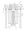
- FIG. 4 is a diagram illustrating the target generation device 20 according to the present embodiment.
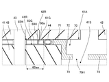
- FIG. 5 is an enlarged view of a region surrounded by a broken line in FIG. 4, and shows a state where the lid body 42 is fixed on the peripheral edge portion 41 ⁇ / b> R of the tank main body 41 with the bolts 43.
- the width 41Gw of the groove 41G formed in the peripheral portion 41R of the tank body 41 of the present embodiment is formed larger than the width 41Gw of the groove 41G in the comparative example.
- the collar 60 is disposed on the outer peripheral side in the groove 41G.
- FIG. 6 shows a color.
- the collar 60 is a circular ring-shaped member, and the thickness of the collar 60 is slightly thinner than the depth of the groove 41G.
- the collar 60 is formed to be about 0.1 mm thinner than the depth of the groove 41G.
- the thickness of the collar 60 is 1.15 mm. It is said.
- the depth of the groove 41G is made smaller than the diameter of the tube of the inner O-ring 44 as in the comparative example. Therefore, the inner O-ring 44 is deformed so as to be crushed by the pressing force from the lid body 42 in a state where the bolt 43 is tightened and the lid body 42 is fixed to the tank body 41. In this state, the outer peripheral surface of the inner O-ring 44 is in contact with the inner peripheral surface of the collar 60, and a gap is formed between the inner O-ring 44 and the inner wall of the groove 41G. .
- the width of this gap is, for example, about 0.2 mm.
- the height of the first support portion 46 is the groove 41G. It is equivalent to the depth of.
- the first support 46 integrated with the tank main body 41 is disposed so as to surround the opening 41 ⁇ / b> A in a region closer to the opening 41 ⁇ / b> A than the bolt 43, and supports the lid 42.
- the width 46w of the first support portion 46 is, for example, 25 mm.
- the second support portion which is a separate body from the tank main body 41, is an area between the tank main body 41 and the lid body 42 on the opening 41A side than the first support portion 46.
- the inner O-ring 44 as a sealing member is disposed in a region closer to the opening 41A than the second support portion.
- the thickness of the collar 60 is the height of the second support portion, and the thickness of the collar 60 is made thinner than the depth of the groove 41G as described above, so the second support portion is the first support portion 46. It will have a height lower than the height.
- the width 60w of the collar 60 which is the second support portion is larger than the thickness of the collar 60, for example, 4.8 to 11.2 mm.
- the width 60w of the collar 60 is, for example, the diameter of the tube of the inner O-ring 44 before being deformed to be crushed. 3 times to 7 times.
- the width 60 w of the collar 60 that is the second support portion is smaller than the width 46 w of the first support portion 46.
- the height of the third support portion 47 is equal to the height of the first support portion 46. Accordingly, the third support portion 47 supports the lid body 42 together with the first support portion 46.
- the width 47w of the third support portion 47 is, for example, 1 to 1.15 mm. In this embodiment, the width 47w of the third support portion 47 is larger than the width 46w of the first support portion 46 and the width 60w of the collar 60. It is made smaller.
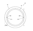
- FIG. 7 is a cross-sectional view of the collar 60 taken along line VV in FIG.
- the collar 60 has a front surface 61 and a back surface 62.
- the thickness of the inner peripheral portion 63 is larger than the thickness of the outer peripheral portion 64, and on the front surface 61, the inner peripheral portion 63 is more convex than the outer peripheral portion 64, and the back surface 62 has a substantially flat structure. .
- a plurality of grooves 61G are formed from the inner peripheral side toward the outer peripheral side in the inner peripheral portion 63 that is convex on the front surface, and grooves 62G are formed on the back surface 62 at positions corresponding to the grooves 61G. Yes. Further, a through hole 60H that connects the groove 61G and the groove 62G is formed.
- the collar 60 is preferably made of a material having a thermal expansion coefficient equivalent to that of the bolt 43. When the bolt 43 is made of stainless steel as described above, the bolt 43 is also preferably made of stainless steel. Further, when the target material 271 is made of tin, the collar 60 is preferably made of molybdenum, tantalum, or tungsten, which hardly reacts with tin.
- the front surface 61 faces the lid 42 side
- the back surface 62 faces the bottom side of the groove 41G.
- the groove 61G of the collar 60 forms a passage with the lid 42
- the groove 62G forms a passage with the tank body 41.
- the thickness of the inner peripheral portion 63 of the collar 60 is larger than the thickness of the outer peripheral portion 64 as described above, a gap is formed between the outer peripheral portion 64 and the lid 42 on the surface 61 of the collar 60.
- the lid 42 is formed with a leak check through hole 42R.
- the leak confirmation through hole 42R is formed at a position where at least a portion thereof overlaps the collar 60 in the thickness direction of the lid body 42, and at least a portion thereof overlaps the outer peripheral portion 64 in the present embodiment. Accordingly, the leak check through hole 42R is connected to the gap between the outer peripheral portion 64 and the lid body 42, and the groove 61G is connected to the leak check through hole 42R through the gap. As described above, since the groove 61G and the groove 62G are connected by the through-hole 60H, the passage made of the groove 61G, the passage made of the through-hole 60H, and the passage made of the groove 62G are checked for leakage of the lid 42. The through hole 42R for use and the space on the inner peripheral surface side of the collar 60 are connected.
- the tank 40 of this embodiment has a different structure from the tank 40 of the comparative example as described above.
- the configurations of the target generation device 20 and the EUV light generation device 1 of the present embodiment are the same as those of the comparative example except for the difference in the structure of the tank 40.
- the outer peripheral surface of the inner O-ring 44 is directly applied to the tank main body 41 when the inner O-ring 44 is deformed so that the lid 42 is fixed to the tank main body 41. Abut. Therefore, in the tank 40 of the comparative example, the stress from the inner O-ring 44 is directly transmitted to the tank body 41, and the tank body 41 may be damaged.
- the collar 60 which is a separate body from the tank body 41, receives a force from the inner O-ring 44, thereby suppressing the tank body 41 from being damaged such as cracks. be able to.
- the tank 40 includes a tank body 41 having a space 41S therein and an opening 41A communicating with the space 41S, and an opening 41A and an opening of the tank body 41.
- a lid 42 covering the peripheral edge of 41A, an inner O-ring 44 as a sealing member disposed so as to surround the opening 41A between the tank body 41 and the lid 42, and an outer periphery of the inner O-ring 44
- a tank main body 41 and a separate collar 60 with which the outer peripheral surface of the surrounding inner O-ring 44 abuts are provided.
- the width 60 w of the collar 60 is set to be not less than 3 times and not more than 7 times the diameter of the tube of the inner O-ring 44. Accordingly, the force received by the collar 60 from the inner O-ring 44 can be further reduced from being transmitted to the tank body 41.
- the first support portion 46 is disposed so as to surround the opening 41 ⁇ / b> A in the region on the opening 41 ⁇ / b> A side from the bolt 43 and supports the lid body 42.
- the collar 60 as the second support portion having a height lower than the height of the first support portion 46 is located in the region closer to the opening 41A than the first support portion 46 between the tank body 41 and the lid body 42. It is arranged so as to surround the opening 41A.
- an inner O-ring 44 as a sealing member is disposed between the tank body 41 and the lid body 42 so as to surround the opening 41A in a region closer to the opening 41A than the first support portion 46.
- the lid body 42 can be supported by the first support section 46 closer to the bolt 43 than when the collar 60 as the second support section supports the lid body 42. For this reason, it can suppress that the cover body 42 deform
- the lid 42 has the leak check through hole 42R as described above, and the collar 60 has the leak check through hole 42R and the space on the inner peripheral surface side of the collar 60. A passage connecting the two is formed.
- the inner O-ring 44 as a sealing member is arranged on the inner peripheral side with respect to the collar 60. Therefore, the inside of the tank 40 is evacuated, a gas such as helium is injected from the leak confirmation through hole 42R, and the state of sealing by the inner O-ring 44 can be grasped by observing with a detector of the gas. .
- the position where this detector is provided is not particularly limited as long as it is a position connected to the space 41S of the tank 40.
- the thickness of the outer peripheral portion 64 of the collar 60 is smaller than the thickness of the inner peripheral portion 63, and a gap is formed between the outer peripheral portion 64 and the lid body 42. . For this reason, even if the leak confirmation through hole 42R and the passage are not aligned in the radial direction of the collar 60, the passage connects the leak confirmation through hole 42R and the space on the inner peripheral surface side of the collar 60. obtain.
- a third support portion 47 is provided.
- the third support portion 47 suppresses contact between the target material 271 made of molten metal and the inner O-ring 44. Accordingly, even when the target material 271 and the inner O-ring 44 are chemically reacted with each other, the inner O-ring 44 can be prevented from chemically reacting with the target material 271.
- the third support portion 47 has a height that is higher than the height of the collar 60 that is the second support portion. Accordingly, contact between the target material 271 and the inner O-ring 44 is further suppressed.
- the height of the third support portion 47 is the same as that of the first support portion 46, and the third support portion 47 is in contact with the lid body 42. Accordingly, contact between the target material 271 and the inner O-ring 44 is further suppressed.
- Embodiment 2 Next, a tank, a target generation device, and an EUV light generation device 1 according to Embodiment 2 will be described in detail with reference to the drawings. In the following description, the same components as those described above are denoted by the same reference numerals, and redundant description is omitted unless specifically described.
- FIG. 8 is a diagram illustrating the target generation device 20 according to the present embodiment.
- FIG. 9 is an enlarged view of a region surrounded by a broken line in FIG. 8, and shows a state where the lid body 42 is fixed on the peripheral edge portion 41 ⁇ / b> R of the tank body 41 with the bolts 43.
- the peripheral portion 41R of the tank body 41 of the present embodiment is planar, and the groove 41G formed in the peripheral portion 41R in the comparative example and the first embodiment is not formed.
- the collar 60a is disposed on the peripheral edge portion 41R.
- the collar 60a of the present embodiment is provided from the inner side to the outer side of the bolt 43, and is different from the collar 60 of the first embodiment in that a through hole 65H is formed at a position where the bolt 43 is inserted.
- the lid body 42 is supported by the collar 60a.
- the thickness of the collar 60a is made smaller than the diameter of the tube of the inner O-ring 44.
- the inner O-ring 44 is crushed by the pressing force from the lid body 42 with the bolts 43 tightened and the lid body 42 fixed to the tank main body 41 as in the first embodiment. It is deformed. In this state, the outer peripheral surface of the inner O-ring 44 is in contact with the inner peripheral surface of the collar 60a.
- the leak confirmation through hole 42R in the present embodiment is formed at a position at least partially overlapping the collar 60a in the thickness direction of the lid body 42. More specifically, the leak confirmation through hole 42R is formed at a position at least partially overlapping with the through hole 60H in the thickness direction of the lid body 42.
- the bolt 43 is inserted into the through hole 65H as described above, the collar 60 is prevented from rotating in the circumferential direction. Accordingly, the relative position between the leak check through hole 42R and the through hole 60H of the collar 60a is prevented from shifting.
- a cover 70 is further provided.
- the cover 70 includes a holding part 71, a hanging part 72, and a cover part 73.
- the holding part 71 is a part on the outermost periphery of the cover 70 and is arranged on the peripheral part 41R to hold the cover 70 so that it does not fall.
- the thickness of the holding portion 71 is made smaller than the thickness of the collar 60a, and is made thinner by, for example, about 0.1 mm than the thickness of the collar 60a. Further, a gap is formed between the outer peripheral surface of the holding portion 71 and the inner surface of the inner O-ring 44.
- the hanging portion 72 is connected to the holding portion 71, extends in a direction perpendicular to the radial direction of the lid body 42, and enters the space 41 ⁇ / b> S of the tank body 41.
- the cover 73 covers the space 41S.
- a gas passage through hole 70H is formed at a position shifted from the center of the opening 41A.
- the lid body 42 is formed with a through-hole through which the pipe 121 serving as a gas passage communicates substantially in the center, and the position of this gas passage overlaps with the substantially center of the opening 41A. Therefore, the gas passage through hole 70 ⁇ / b> H formed in the cover 70 is positioned so as not to overlap the gas passage formed in the lid 42.
- the size of the gas passage through hole 70 ⁇ / b> H is equal to or larger than the size of the gas passage formed in the lid 42.
- the diameter of the gas passage in the lid 42 is 8 mm
- the diameter of the gas passage through hole 70 ⁇ / b> H formed in the cover 70 is 10 mm.
- the cover 70 having such a configuration is made of a material that does not react with the target material 271 made of molten metal.
- the cover 70 is preferably made of molybdenum, tantalum, or tungsten.
- the first support portion which is a separate body from the tank body 41, is disposed so as to surround the opening 41A in the region closer to the opening 41A than the bolt 43.
- the lid 42 is supported.
- the second support portion which is a separate body from the tank main body 41, is closer to the opening 41 ⁇ / b> A than the first support portion between the tank main body 41 and the lid body 42. In the region, the opening 41A is disposed.
- the inner O-ring 44 as a sealing member is disposed in a region between the first support portion and the second support portion.
- the second support portion is the first support portion. It will have a height lower than the height.
- the width 60aw from the inner peripheral surface of the collar 60a to the through hole 65H for inserting the bolt 43 is larger than the thickness of the collar 60a, and is not less than 3 times and not more than 7 times the diameter of the tube of the inner O-ring 44.
- the collar 60a which is a separate body from the tank body 41, receives a force from the inner O-ring 44, so that the stress transmitted from the inner O-ring 44 to the tank body 41 is relieved. Can do.
- the peripheral edge portion 41R of the tank body 41 in which the collar 60a is disposed is planar, even if the collar 60a spreads to the outer peripheral side due to the force that the inner O-ring 44 spreads, It can be suppressed that 60a gives a stress to tank body 41 more. For this reason, according to the tank 40 of this embodiment, it can suppress more that damage, such as a crack, arises in the tank main body 41.
- the collar 60 a that is the first support portion is disposed so as to surround the opening 41 ⁇ / b> A in the region closer to the opening 41 ⁇ / b> A than the bolt 43 to support the lid body 42.
- the holding portion 71 of the cover 70 as the second support portion having a height lower than the height of the collar 60 a that is the first support portion is the first support portion between the tank body 41 and the lid body 42.
- the opening 41A is surrounded.
- an inner O-ring 44 as a sealing member is disposed between the tank main body 41 and the lid 42 so as to surround the opening 41A in a region closer to the opening 41A than the collar 60a.
- the lid body 42 can be supported by the collar 60 a as the first support portion closer to the bolt 43 than when the holding portion 71 as the second support portion supports the lid body 42. For this reason, it can suppress that the cover body 42 deform
- FIG. 1
- the inner O-ring 44 as a sealing member is disposed between the collar 60a that is the first support portion that supports the lid 42 and the holding portion 71 that is the second support portion. Accordingly, the target material 271 made of molten metal can be prevented from coming into contact with the inner O-ring 44 by the second support portion without having the third support portion as in the first embodiment.
- the cover portion 73 of the cover 70 covers the space 41 ⁇ / b> S of the tank body 41. Therefore, even when the target material 271 made of molten metal scatters, the cover 73 can prevent the molten metal from exceeding the cover 73 and the molten metal comes into contact with the inner O-ring 44. Can be more effectively suppressed.
- the gas passage through hole 70H formed in the cover portion 73 as described above is formed at a position shifted from the center position of the opening 41A of the tank body 41.
- the tank 40 can be tilted with respect to the vertical direction so that the gas passage through hole 70H is above the axis passing through the center of the opening 41A, that is, opposite to the direction of gravity.
- the liquid level of the target material 271 that is a molten metal can be kept away from the gas passage through hole 70H.
- the target material 271 can be prevented from passing through the gas passage through hole 70H, and the molten metal can be more effectively brought into contact with the inner O-ring 44. Can be suppressed.
- the gas passage through hole 70 ⁇ / b> H formed in the cover portion 73 is formed at a position that does not overlap with the gas passage formed in the lid 42. Therefore, when a gas such as argon or nitrogen is filled from the gas passage, the cover portion 73 suppresses the gas from entering the space 41S of the tank 40 straight from the gas passage. That is, the momentum of the gas flow is suppressed by the cover portion 73. For this reason, it is possible to prevent the target material 271 made of molten metal from being scattered by the gas introduced into the space 41S.
- the cross-sectional area of the gas passage through hole 70H is larger than the cross-sectional area of the gas passage formed in the lid body 42.
- Embodiment 3 Next, a tank, a target generation device, and an EUV light generation device 1 according to Embodiment 3 will be described in detail with reference to the drawings. In the following description, the same components as those described above are denoted by the same reference numerals, and redundant description is omitted unless specifically described.
- FIG. 10 is a diagram illustrating the target generation device 20 according to the present embodiment.
- FIG. 11 is an enlarged view of a region surrounded by a broken line in FIG. 10, and shows a state where the lid body 42 is fixed on the peripheral edge portion 41 ⁇ / b> R of the tank main body 41 with the bolts 43.
- the tank 40 of the present embodiment is different from the tank 40 of the second embodiment in that the cover 70 is not provided. Therefore, in the tank 40 of the present embodiment, the target material 271 made of molten metal is likely to come into contact with the inner O-ring 44 as a sealing member, as compared with the tank 40 of the second embodiment. For this reason, the surface of the inner O-ring 44 of this embodiment is made of a material that does not chemically react with the target material 271. For example, when the target material 271 is tin, the surface of the inner O-ring 44 is made of molybdenum, tantalum, or tungsten. More preferably, the entire inner O-ring 44 is made of a material that does not chemically react with the target material 271.
- the tank 40 of this embodiment a member that suppresses contact between the inner O-ring 44 that is a sealing member and the target material 271 can be omitted. Therefore, the configuration of the tank 40 can be simplified.
- the sealing member of the said Embodiment 1 and 2 also consists of a material which does not chemically react with the target material 271 similarly to this embodiment.
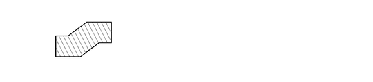
- FIG. 12A is a diagram illustrating an example of a cross section of a gasket that can be used as a sealing member.
- a metal gasket having such a cross section may be formed in a ring shape and used as a sealing member.
- FIG. 12B is a diagram illustrating an example of a cross section of another gasket that can be used as a sealing member.
- a metal gasket having such a cross section may be formed in a ring shape and used as a sealing member.
- FIG. 12C is a diagram illustrating an example of a cross section of still another gasket that can be used as a sealing member.
- a metal gasket having such a cross section may be formed in a ring shape and used as a sealing member.
- FIG. 12D is a view showing an example of a cross section of still another gasket that can be used as a sealing member.
- a metal gasket having such a cross section may be formed in a ring shape and used as a sealing member.
- the surface of the gasket shown in FIGS. 12A to 12D is preferably made of a material that does not chemically react with the target material 271.
- the target material 271 is tin
- the surface of the gasket is preferably made of any one of molybdenum, tantalum, and tungsten.
- a member other than the O-ring can be used as the sealing member.
Landscapes
- Physics & Mathematics (AREA)
- Engineering & Computer Science (AREA)
- Plasma & Fusion (AREA)
- Optics & Photonics (AREA)
- General Physics & Mathematics (AREA)
- X-Ray Techniques (AREA)
- Exposure And Positioning Against Photoresist Photosensitive Materials (AREA)
Abstract
タンク(40)は、内部に空間(41S)を有し空間(41S)と通じる開口(41A)を有するタンク本体(41)と、タンク本体(41)の開口(41A)及び開口(41A)の周縁部(41R)を覆う蓋体(42)と、周縁部(41R)においてタンク本体(41)と蓋体(42)とを固定するボルト(43)と、ボルト(43)よりも開口(41A)側の領域において開口(41A)を囲んで配置され蓋体(42)を支える第1支持部と、タンク本体(41)と蓋体(42)との間における第1支持部よりも開口(41A)側の領域において開口(41A)を囲んで配置され、第1支持部の高さよりも低い高さを有する第2支持部と、タンク本体(41)と蓋体(42)との間における第1支持部よりも開口(41A)側の領域において開口(41A)を囲んで 配置される封止部材と、を備えてもよい。
Description
本開示は、タンク、ターゲット生成装置、及び、極端紫外光生成装置に関する。
近年、半導体プロセスの微細化に伴って、半導体プロセスの光リソグラフィにおける転写パターンの微細化が急速に進展している。次世代においては、20nm以下の微細加工が要求されるようになる。このため、波長13nm程度の極端紫外(EUV:extreme ultraviolet)光を生成するための装置と縮小投影反射光学系(reduced projection reflective optics)とを組み合わせた露光装置の開発が期待されている。
EUV光生成装置としては、ターゲット物質にレーザ光を照射することによって生成されるプラズマが用いられるLPP(Laser Produced Plasma)式の装置と、放電によって生成されるプラズマが用いられるDPP(Discharge Produced Plasma)式の装置と、軌道放射光が用いられるSR(Synchrotron Radiation)式の装置との3種類の装置が提案されている。
本開示の一態様によるタンクは、内部に空間を有し空間と通じる開口を有するタンク本体と、タンク本体の開口及び開口の周縁部を覆う蓋体と、周縁部においてタンク本体と蓋体とを固定するボルトと、ボルトよりも開口側の領域において開口を囲んで配置され蓋体を支える第1支持部と、タンク本体と蓋体との間における第1支持部よりも開口側の領域において開口を囲んで配置され、第1支持部の高さよりも低い高さを有する第2支持部と、タンク本体と蓋体との間における第1支持部よりも開口側の領域において開口を囲んで配置される封止部材と、を備えてもよい。
本開示の一態様によるターゲット生成装置は、内部に溶融金属が充填される空間を有し空間と通じる開口を有するタンク本体と、タンク本体の開口及び開口の周縁部を覆う蓋体と、周縁部においてタンク本体と前記蓋体とを固定するボルトと、ボルトよりも開口側の領域において開口を囲んで配置され蓋体を支える第1支持部と、タンク本体と蓋体との間における第1支持部よりも開口側の領域において開口を囲んで配置され、第1支持部の高さよりも低い高さを有する第2支持部と、タンク本体と蓋体との間における第1支持部よりも開口側の領域において開口を囲んで配置される封止部材と、タンク本体に接続されチャンバ内において空間内の溶融金属からなるターゲットを吐出するノズルと、を備えてもよい。
また、本開示の一態様による極端紫外光生成装置は、内部に溶融金属が充填される空間を有し空間と通じる開口を有するタンク本体と、タンク本体の開口及び開口の周縁部を覆う蓋体と、周縁部においてタンク本体と蓋体とを固定するボルトと、ボルトよりも開口側の領域において開口を囲んで配置され蓋体を支える第1支持部と、タンク本体と蓋体との間における第1支持部よりも開口側の領域において開口を囲んで配置され、第1支持部の高さよりも低い高さを有する第2支持部と、タンク本体と蓋体との間における第1支持部よりも開口側の領域において開口を囲んで配置される封止部材と、タンク本体に接続されチャンバ内において空間内の溶融金属からなるターゲットを吐出するノズルと、ノズルから出力されたターゲットへレーザ光を照射するレーザ装置と、レーザ光が照射されることで生成されるターゲットのプラズマから放射した極端紫外光を集光して出力する集光ミラーと、を備えてもよい。
本開示のいくつかの実施形態を、単なる例として、添付の図面を参照して以下に説明する。
図1は、比較例にかかるEUV光生成装置の概略構成例を示す模式図である。
図2は、図1のターゲット生成装置を示す図である。
図3は、図2の破線で囲まれた領域の拡大図である。
図4は、実施形態1にかかるターゲット生成装置を示す図である。
図5は、図4の破線で囲まれた領域の拡大図である。
図6は、図5のカラーを示す図である。
図7は、図6におけるV-V線でのカラーの断面図である。
図8は、実施形態2にかかるターゲット生成装置を示す図である。
図9は、図8の破線で囲まれた領域の拡大図である。
図10は、実施形態3にかかるターゲット生成装置を示す図である。
図11は、図10の破線で囲まれた領域の拡大図である。
図12Aは、封止部材として用いることができるガスケットの断面の例を示す図である。
図12Bは、封止部材として用いることができる他のガスケットの断面の例を示す図である。
図12Cは、封止部材として用いることができる更に他のガスケットの断面の例を示す図である。
図12Dは、封止部材として用いることができるまた更に他のガスケットの断面の例を示す図である。
1.概要
2.比較例
2.1 構成
2.2 動作
3.実施形態1
3.1 構成
3.2 作用・効果
4.実施形態2
4.1 構成
4.2 作用・効果
5.実施形態3
5.1 構成
5.2 作用・効果
2.比較例
2.1 構成
2.2 動作
3.実施形態1
3.1 構成
3.2 作用・効果
4.実施形態2
4.1 構成
4.2 作用・効果
5.実施形態3
5.1 構成
5.2 作用・効果
以下、本開示の実施形態について、図面を参照しながら詳しく説明する。
以下に説明される実施形態は、本開示のいくつかの例を示すものであって、本開示の内容を限定するものではない。また、各実施形態で説明される構成及び動作の全てが本開示の構成及び動作として必須であるとは限らない。
なお、同一の構成要素には同一の参照符号を付して、重複する説明を省略する。
以下に説明される実施形態は、本開示のいくつかの例を示すものであって、本開示の内容を限定するものではない。また、各実施形態で説明される構成及び動作の全てが本開示の構成及び動作として必須であるとは限らない。
なお、同一の構成要素には同一の参照符号を付して、重複する説明を省略する。
1.概要
本開示の実施形態は、タンク、ターゲット生成装置、及び、極端紫外光生成装置に関するものである。例えば、タンクにクラック等の損傷が生じることを抑制し得るタンク、ターゲット生成装置、及び、極端紫外光生成装置に関するものである。以下、極端紫外光をEUV光と呼ぶ場合がある。従って、極端紫外光生成装置をEUV光生成装置という場合がある。
本開示の実施形態は、タンク、ターゲット生成装置、及び、極端紫外光生成装置に関するものである。例えば、タンクにクラック等の損傷が生じることを抑制し得るタンク、ターゲット生成装置、及び、極端紫外光生成装置に関するものである。以下、極端紫外光をEUV光と呼ぶ場合がある。従って、極端紫外光生成装置をEUV光生成装置という場合がある。
2.比較例
まず、タンク、ターゲット生成装置、及び、EUV光生成装置の比較例を、図面を参照して詳細に説明する。
まず、タンク、ターゲット生成装置、及び、EUV光生成装置の比較例を、図面を参照して詳細に説明する。
2.1 構成
図1は、比較例にかかるEUV光生成装置の概略構成例を示す模式図である。図1に示すように、EUV光生成装置1は、チャンバ2、レーザ光進行方向コントローラ34および制御部5を含んでいる。このEUV光生成装置1には、通常、レーザ装置3が追加されて使用される。
図1は、比較例にかかるEUV光生成装置の概略構成例を示す模式図である。図1に示すように、EUV光生成装置1は、チャンバ2、レーザ光進行方向コントローラ34および制御部5を含んでいる。このEUV光生成装置1には、通常、レーザ装置3が追加されて使用される。
チャンバ2は、ターゲット生成装置20と、レーザ集光光学系220と、EUV集光ミラー23と、ターゲット回収部28と、排気装置210とを含む。レーザ集光光学系220は、レーザ光集光ミラー22および高反射ミラー222を搭載する移動プレート221とレーザ光マニュピレータ223とを含む。
ターゲット生成装置20は、チャンバ2に連設されたサブチャンバ201に設けられている。ターゲット生成装置20は、タンク40と、ノズル50とを含む。タンク40は、その内部に溶融金属からなるターゲット材料271を貯蔵する。ターゲット材料271としては、例えば、錫、テルビウム、ガドリニウム、リチウム、キセノン、又は、それらの内のいずれか2つ以上の組合せを挙げることができる。ノズル50は、ターゲット材料271をドロップレット状のターゲット27として出力する。また、タンク40の内部は、ガス圧を調整する圧力調節器120と配管121を介して連通している。なお、以下、タンク40の内部のガス圧をタンク内圧力という場合がある。
ピエゾ素子111はノズル50に設置されている。ピエゾ素子111はピエゾ電源112に、ヒータ141はヒータ電源143に、それぞれ接続されている。温度センサ142およびヒータ141はタンク本体に配置されている。ピエゾ電源112、圧力調節器120、温度センサ142およびヒータ電源143は、それぞれ制御部5に接続されている。
レーザ光進行方向コントローラ34は、レーザ光の進行方向を規定するための光学素子と、この光学素子の位置、姿勢等を調整するためのアクチュエータとを備えている。チャンバ2の壁には、ウィンドウ21が設けられており、ウィンドウ21をレーザ装置3から出力され、レーザ光進行方向コントローラ34で進行方向が調整されたパルスレーザ光32が透過する。レーザ集光光学系220は、レーザ光進行方向コントローラ34から出射されるパルスレーザ光32が入射されるように配置されている。レーザ光マニュピレータ223は、チャンバ2内でのレーザ集光位置が制御部5から指定された位置となるように、レーザ光集光ミラー22および高反射ミラー222が固定された移動プレート221をX軸、Y軸およびZ軸方向に移動する。
EUV集光ミラー23は、第1及び第2の焦点を有する。EUV集光ミラー23の表面には、例えば、モリブデンとシリコンとが交互に積層された多層反射膜が形成されている。EUV集光ミラー23は、例えば、その第1の焦点がプラズマ生成領域25に位置し、その第2の焦点が中間集光点(IF)292に位置するように配置されるのが好ましい。EUV集光ミラー23の中央部には、パルスレーザ光33が通過する貫通孔24が設けられている。
EUV光生成装置1は、制御部5、ターゲットセンサ4等を含んでいる。ターゲットセンサ4は、撮像機能を有しており、ターゲット27の存在、軌跡、位置、速度等を検出するよう構成される。
また、EUV光生成装置1は、チャンバ2の内部と露光装置6の内部とを連通させる接続部29を含んでいる。接続部29内部には、アパーチャ293が形成された壁291が設けられている。壁291は、そのアパーチャ293がEUV集光ミラー23の第2の焦点位置に位置するように配置されることが好ましい。
また、ターゲット回収部28は不要なターゲット27を回収する。
また、EUV光生成装置1は、水素ガス供給部301と、流量調節器302と、ガスノズル303と、ガス管304とを備える。また、EUV光生成装置1は、圧力センサ305をさらに備える。
水素ガス供給部301は、ガス管304を介してガスノズル303に接続されている。水素ガス供給部301は、たとえば水素ガス濃度が3%程度のバランスガスをガス管304に供給する。バランスガスには、窒素(N2)ガスやアルゴン(Ar)ガスが含まれていてもよい。
ガスノズル303は、吹出した水素ガスがターゲット生成装置20のノズル50付近を流れるように、サブチャンバ201に設けられている。水素ガス供給部301とガスノズル303との間のガス管304には、流量調節器302が設けられている。
圧力センサ305には、冷陰極電離真空計、ピラニ真空計、キャパシタンスマノメータなどが用いられている。また、排気装置210は、チャンバ2内の水分を除去する除去装置として使用されている。圧力センサ305および流量調節器302は制御部5に接続されている。
次に、タンク40について詳述する。図2は、図1のターゲット生成装置20の拡大図である。なお、以下の図では、図1に記載のヒータ141、温度センサ142、ピエゾ素子111が省略されている。タンク40は、タンク本体41と蓋体42とを備える。
タンク本体41は、内部に空間41Sを有し上方に当該空間41Sと通じる開口41Aを有する筒状の部材であり、本例では概ね円筒形とされる。タンク本体41は、ターゲット材料271が錫である場合は、例えば、錫と化学反応しにくいモリブデン、タンタル、タングステンからなることが好ましい。タンク本体41の端部である開口41Aの周縁部41Rは蓋体42を支える部位となる。蓋体42は、下面が概ね平面の板状の部材であり、タンク本体41の開口41A、及び、開口41Aの周縁部41Rを覆う。本例では、蓋体42は、タンク本体41の開口41Aを覆うと共にチャンバ2の開口を覆っている。蓋体42は、複数のボルト43が周縁部41Rにおいてタンク本体41に螺入されることで、タンク本体41に固定されている。ボルト43の数は例えば16本とされる。蓋体42は、例えばステンレススチールから形成されている。また、ボルト43は、蓋体42と同じ材料から成ることが好ましく、例えばステンレススチールから形成されている。
図3は、図2の破線で囲まれた領域の拡大図であり、タンク本体41の周縁部41R上に蓋体42がボルト43で固定されている様子を示す。図3に示すように、タンク本体41の周縁部41Rには、ボルト43よりも開口41A側、すなわちボルト43よりも内周側において、開口41Aを取り囲むように封止部材配置用の溝41Gが形成されている。この溝41G内には、全周に渡って、封止部材としての内側O-リング44が配置されている。内側O-リング44は、チューブ状の部材がリング状に形成されたものである。本例では、内側O-リング44は金属からなっており、例えば、チューブ状のステンレススチールの外表面に銀めっきが施されたものからなる。溝41Gの幅41Gwは内側O-リング44のチューブの直径よりも大きくされており、溝41Gの深さは内側O-リング44のチューブの直径よりも小さくされている。例えば、溝41Gの深さが1.25mmとされ、内側O-リングのチューブの直径が1.6mmとされる。このため、蓋体42が配置されない状態では、溝41G内に配置された内側O-リング44の一部が溝41Gから上方にはみ出ている。そして、蓋体42が周縁部41R上に配置され、ボルト43が締められた状態で、内側O-リング44は、蓋体42からの押圧力により潰れるように変形して、タンク本体41と蓋体42との間の隙間を埋めて、ボルト43の内側においてタンク40を封止する。このとき、上記のように内側O-リング44がステンレススチールの外表面に銀めっきが施されているものである場合、銀めっきが微小変形して細かい隙間を埋めるため好ましい。また、ボルト43が締められて内側O-リング44が変形した状態で、内側O-リング44の外周側の面は溝41Gの外側の壁に当接しており、内側O-リング44と溝41Gの内側の壁との間には隙間が形成されている。このように内側O-リング44の外周側の面が溝41Gの外側の壁に当接することで、内側O-リング44が潰れるように変形する際、内側O-リング44の広がりが抑制され、内側O-リング44が十分な反発力を生じ得る。内側O-リング44が十分な反発力を発生するために、上記のように例えば内側O-リング44のチューブの直径が1.6mmとされる場合に、チューブの肉厚は例えば0.35mmとされる。
また、タンク本体41の周縁部41Rには、ボルト43を基準として開口41A側と反対側、すなわちボルト43よりも外周側において、開口41Aを取り囲むように封止部材配置用の溝41Nが形成されている。この溝41Nには封止部材としての外側O-リング45が配置されている。外側O-リング45の構成は、例えば、直径を除き内側O-リング44と同様の構成とされる。溝41Nの深さは、例えば溝41Gと同様とされる。従って、外側O-リング45は、蓋体42が配置されボルト43が締められた状態で、潰れるように変形して、タンク本体41と蓋体42との間の隙間を埋めて、ボルト43の外側において、タンク40を封止する。
また、蓋体42の概ね中央には貫通孔が形成されており、この貫通孔に配管121が連通しており、ガス通路が形成されている。このガス通路の直径は、例えば8mmとされる。こうして上記のようにタンク40の内部が圧力調節器120と連通し、圧力調節器120により、タンク本体41の空間41Sの圧力が調整される。
なお、ノズル50は、図2に示すようにタンク本体41における下方において、複数のボルト51によりタンク本体41に固定されている。ノズル50にはノズル孔が形成されており、当該ノズル孔とタンク本体41の下方の開口とが連通しており、ノズル孔からタンク本体41内のターゲット材料を出力可能とされる。
また、図2に示すように、チャンバ2の蓋体42と接する周縁部2Rには、封止部材配置用の溝2Gが形成されている。この溝2G内には、全周に渡って、封止部材としてのチャンバ用O-リング204が配置されている。チャンバ用O-リング204は、例えば、直径を除いて内側O-リング44と同様の形状とされ、チャンバ用O-リング204の材料は、例えば、内側O-リング44と同様の材料から構成されても樹脂で構成されてもよい。このチャンバ用O-リング204は、蓋体42がチャンバ2の周縁部2R上に配置され、ボルト43が締められた状態で、潰れるように変形して、チャンバ2と蓋体42との間の隙間を埋めてチャンバ2を封止する。
以上の構成のチャンバ2内は概ね真空とされ、後述のように僅かに水素等のガスが残存している程度とされる。また、タンク40内の空間41Sにおけるターゲット材料271が充填されていない領域には、アルゴン等の不活性ガスが充填されている。タンク40内の圧力は、例えば40MPaとされる。この様にタンク40の内部は高圧とされるため、内側O-リング44は、ボルト43の締め付けによる蓋体42からの押圧力により潰れた状態で、タンク40内のガスがリークしないよう、高い反発力でタンク本体41と蓋体42とを押し返す。
2.2 動作
ターゲット生成装置20は、例えば、メンテナンス時等において、それぞれのボルト43が締めつけられることで、チャンバ2に組付けられる。ターゲット生成装置20が組みつけられた状態で、制御部5は、チャンバ2内の大気を排気するために排気装置210を動作させる。その際、大気成分の排気のために、チャンバ2内のパージと排気とを繰り返してもよい。パージガスには、例えば、窒素(N2)やアルゴン(Ar)などの不活性ガスが用いられることが好ましい。また、排気装置210による排気の結果、チャンバ内圧力が第1の所定圧力以下になると、制御部5は、水素ガス供給部301からチャンバ2内への水素ガスの導入を開始する。水素ガスは、低流量でチャンバ2内に導入されることが好ましい。このとき制御部5は、圧力センサ305の値が第2の所定圧力に維持されるように、流量調節器302を制御してもよい。その後、制御部5は、水素ガスの導入開始から所定時間が経過するまで待機する。
ターゲット生成装置20は、例えば、メンテナンス時等において、それぞれのボルト43が締めつけられることで、チャンバ2に組付けられる。ターゲット生成装置20が組みつけられた状態で、制御部5は、チャンバ2内の大気を排気するために排気装置210を動作させる。その際、大気成分の排気のために、チャンバ2内のパージと排気とを繰り返してもよい。パージガスには、例えば、窒素(N2)やアルゴン(Ar)などの不活性ガスが用いられることが好ましい。また、排気装置210による排気の結果、チャンバ内圧力が第1の所定圧力以下になると、制御部5は、水素ガス供給部301からチャンバ2内への水素ガスの導入を開始する。水素ガスは、低流量でチャンバ2内に導入されることが好ましい。このとき制御部5は、圧力センサ305の値が第2の所定圧力に維持されるように、流量調節器302を制御してもよい。その後、制御部5は、水素ガスの導入開始から所定時間が経過するまで待機する。
制御部5は、タンク40内のターゲット材料271を融点以上の所定温度に加熱および維持するために、ヒータ電源143から電流を供給してヒータ141を昇温する。また、制御部5は、温度センサ142からの出力に基づいて、ヒータ電源143からヒータ141へ供給する電流量を調整し、ターゲット材料271の温度を所定温度に制御する。なお、所定温度は、ターゲット材料271に錫を用いた場合、例えば250℃~290℃の温度範囲内の温度とされる。
制御部5は、ノズル50のノズル孔から溶融したターゲット材料271が所定の速度で出力するように、圧力調節器120によってタンク内圧力を所定圧力に制御する。ノズル孔から吐出するターゲット材料271はジェットの形態をとってもよい。
制御部5は、ターゲット材料271のターゲット27を生成するために、ピエゾ電源112を介してピエゾ素子111に所定波形の電圧を印加する。ピエゾ素子111の振動は、ノズル50を経由してノズル孔から出力されるターゲット材料271のジェットへと伝搬し得る。ターゲット材料271のジェットは、この振動により所定周期で分断される。それにより、ターゲット材料271のターゲット27が生成され、生成されたターゲット27は液滴となる。
制御部5は、発光トリガをレーザ装置3に出力する。発光トリガが入力されると、レーザ装置3は、パルスレーザ光31を出力する。出力されたパルスレーザ光31は、レーザ光進行方向コントローラ34とウィンドウ21とを経由して、レーザ集光光学系220にパルスレーザ光32として入射される。
制御部5は、パルスレーザ光32がプラズマ生成領域25で集光するように、レーザ光マニュピレータ223を制御する。レーザ光集光ミラー22で収束光に変換されたパルスレーザ光33は、プラズマ生成領域25でターゲット27に照射される。この照射により生成したプラズマから、EUV光252が発生する。所定周期でプラズマ生成領域25に供給されるターゲット27にパルスレーザ光33が照射されることにより、EUV光252が周期的に発生する。
プラズマ生成領域25から発生したEUV光252は、図1を用いて説明したように、EUV集光ミラー23によって中間集光点292で集光された後、露光装置6に入力する。
2.3 課題
上記のようにタンク40内の圧力は、例えば40MPaとされる。この様に高い圧力のタンク40内を封止する内側O-リング44は、チューブが潰れて変形することによる大きな反発力が生じ得る。このため、内側O-リング44が潰れる際に外側に広がろうとする力も大きくなる。しかし、本例では内側O-リング44の外周面は、タンク本体41の一部である溝41Gの外側の壁に当接する。従って、タンク本体41には、内側O-リング44のチューブが元に戻ろうとする反発力のみならず、内側O-リング44が変形することで外側に広がろうとする力が直接加わることになる。従って、タンク本体41の強度を高くしなければ、タンク本体41が変形したりクラックが生じたりする可能性があるという懸念がある。
上記のようにタンク40内の圧力は、例えば40MPaとされる。この様に高い圧力のタンク40内を封止する内側O-リング44は、チューブが潰れて変形することによる大きな反発力が生じ得る。このため、内側O-リング44が潰れる際に外側に広がろうとする力も大きくなる。しかし、本例では内側O-リング44の外周面は、タンク本体41の一部である溝41Gの外側の壁に当接する。従って、タンク本体41には、内側O-リング44のチューブが元に戻ろうとする反発力のみならず、内側O-リング44が変形することで外側に広がろうとする力が直接加わることになる。従って、タンク本体41の強度を高くしなければ、タンク本体41が変形したりクラックが生じたりする可能性があるという懸念がある。
3.実施形態1
次に実施形態1にかかるタンク、ターゲット生成装置およびEUV光生成装置を、図面を参照して詳細に説明する。なお、以下の説明では、上述において説明した構成と同様の構成については、同一の符号を付し、特に説明する場合を除き、重複する説明を省略する。
次に実施形態1にかかるタンク、ターゲット生成装置およびEUV光生成装置を、図面を参照して詳細に説明する。なお、以下の説明では、上述において説明した構成と同様の構成については、同一の符号を付し、特に説明する場合を除き、重複する説明を省略する。
3.1 構成
図4は、本実施形態にかかるターゲット生成装置20を示す図である。また、図5は、図4の破線で囲まれた領域の拡大図であり、タンク本体41の周縁部41R上に蓋体42がボルト43で固定されている様子を示す。
図4は、本実施形態にかかるターゲット生成装置20を示す図である。また、図5は、図4の破線で囲まれた領域の拡大図であり、タンク本体41の周縁部41R上に蓋体42がボルト43で固定されている様子を示す。
図4、図5に示すように、本実施形態のタンク本体41の周縁部41Rに形成される溝41Gの幅41Gwは、上記比較例における溝41Gの幅41Gwよりも大きく形成されている。さらに、本実施形態では、溝41G内における外周側にはカラー60が配置されている。図6はカラーを示す図である。図6に示すようにカラー60は円形のリング状の部材とされ、カラー60の厚さは、溝41Gの深さよりも僅かに薄くされている。例えば、カラー60は溝41Gの深さよりも0.1mm程度薄く形成され、例えば、上記のように溝41Gの深さが1.25mmとされるのであれば、カラー60の厚さは1.15mmとされる。本実施形態においても、上記比較例と同様に溝41Gの深さは内側O-リング44のチューブの直径よりも小さくされる。従って、ボルト43が締められて蓋体42がタンク本体41に固定された状態で、内側O-リング44は蓋体42からの押圧力により潰れるように変形している。この状態において、内側O-リング44の外周側の面はカラー60の内周面に当接しており、内側O-リング44と溝41Gの内側の壁との間には隙間が形成されている。この隙間の幅は、例えば概ね0.2mm程度とされる。
このような構成を有するタンク40において、溝41Gと複数のボルト43との間のタンク本体41の周回状の部位を第1支持部46とすると、第1支持部46の高さは、溝41Gの深さと同等となる。このタンク本体41と一体とされる第1支持部46は、ボルト43よりも開口41A側の領域において開口41Aを囲んで配置され、蓋体42を支える。第1支持部46の幅46wは、例えば25mmとされる。
また、カラー60を第2支持部とすると、タンク本体41と別体とされる第2支持部は、タンク本体41と蓋体42との間における第1支持部46よりも開口41A側の領域において開口41Aを囲んで配置される。また、封止部材である内側O-リング44は、第2支持部よりも開口41A側の領域に配置される。また、カラー60の厚さは第2支持部の高さであり、上記のようにカラー60の厚さは溝41Gの深さよりも薄くされているため、第2支持部は第1支持部46の高さよりも低い高さを有することとなる。第2支持部であるカラー60の幅60wは、カラー60の厚さよりも大きく、例えば4.8~11.2mmとされる。従って、例えば上記のように内側O-リング44のチューブの直径が1.6mmとされる場合、カラー60の幅60wは、例えば潰れるように変形される前における内側O-リング44のチューブの直径の3倍以上7倍以下とされる。また、本実施形態では、第2支持部であるカラー60の幅60wは、第1支持部46の幅46wより小さくされる。
また、開口41Aと溝41Gとの間のタンク本体41の周回状の部位を第3支持部47とすると、第3支持部47の高さは第1支持部46の高さと同等となる。従って、第3支持部47は、第1支持部46と共に蓋体42を支える。第3支持部47の幅47wは、例えば1~1.15mmとされ、本実施形態では、第3支持部47の幅47wは、第1支持部46の幅46w、カラー60の幅60wよりも小さくされる。
次にカラー60についてより詳しく説明する。図7は、図6におけるV-V線でのカラー60の断面図である。図6、図7に示すようにカラー60は、表面61、裏面62を有する。カラー60は、内周部63の厚さが外周部64の厚さよりも大きく、表面61において、内周部63が外周部64よりも凸状とされ、裏面62は概ね平坦な構造とされる。また、表面において凸状とされる内周部63には、複数の溝61Gが内周側から外周側に向かって形成され、裏面62においても溝61Gと対応する位置に溝62Gが形成されている。また、溝61Gと溝62Gを繋ぐ貫通孔60Hが形成されている。また、カラー60は、ボルト43と同等の熱膨張係数をもつ材料から成ることが好ましい。上記のようにボルト43がステンレススチールから成る場合、ボルト43もステンレススチールから成ることが好ましい。また、ターゲット材料271が錫から成る場合、カラー60は錫と化学反応しにくいモリブデン、タンタル、タングステンから成ることが好ましい。
図5に示すように、カラー60がタンク本体41の溝41G内に配置された状態で、表面61が蓋体42側を向き、裏面62が溝41Gの底側を向く。この状態で、カラー60の溝61Gは蓋体42との間に通路を形成し、溝62Gはタンク本体41との間に通路を形成する。また、上記のようにカラー60の内周部63の厚さは外周部64の厚さよりも大きいため、カラー60の表面61における外周部64と蓋体42との間には隙間が形成される。また、図5に示すように蓋体42には、リーク確認用貫通孔42Rが形成されている。リーク確認用貫通孔42Rは、蓋体42の厚さ方向においてカラー60と少なくとも一部が重なる位置に形成され、本実施形態では上記外周部64と少なくとも一部が重なっている。従って、リーク確認用貫通孔42Rは、外周部64と蓋体42との間の隙間と接続されており、当該隙間を介して溝61Gがリーク確認用貫通孔42Rと接続されている。上記のように、貫通孔60Hにより、溝61Gと溝62Gとが繋がっているため、溝61Gからなる通路、貫通孔60Hからなる通路、及び、溝62Gからなる通路は、蓋体42のリーク確認用貫通孔42Rとカラー60の内周面側の空間とを接続している。
本実施形態のタンク40は、上記のように比較例のタンク40と異なる構造を有する。また、本実施形態のターゲット生成装置20およびEUV光生成装置1の構成は、タンク40の構造上の違いを除けば、比較例と同様とされる。
3.2 作用・効果
本実施形態では、蓋体42がボルト43によりタンク本体41に固定される際に、蓋体42からの押圧力で封止部材である内側O-リング44が潰れるように変形する。このとき内側O-リング44の外周側の面がカラー60の内周面に当接し、内側O-リング44はカラー60により外側に広がることが抑制される。従って、カラー60は、内側O-リング44から外側に広がる力を受ける。しかし、本実施形態ではタンク本体41と別体であるカラー60が内側O-リング44から力を受けるため、タンク本体41に内側O-リング44から伝わる応力を緩和し得る。これに対し、比較例のタンク40では、蓋体42をタンク本体41に固定する際に内側O-リング44が潰れるように変形する際、内側O-リング44の外周面がタンク本体41に直接当接する。従って、比較例のタンク40では、内側O-リング44からの応力が直接タンク本体41に伝わり、タンク本体41に損傷を与える可能性がある。この様に、本実施形態のタンク40によれば、タンク本体41と別体であるカラー60が内側O-リング44から力を受けるため、タンク本体41にクラック等の損傷が生じることを抑制することができる。
本実施形態では、蓋体42がボルト43によりタンク本体41に固定される際に、蓋体42からの押圧力で封止部材である内側O-リング44が潰れるように変形する。このとき内側O-リング44の外周側の面がカラー60の内周面に当接し、内側O-リング44はカラー60により外側に広がることが抑制される。従って、カラー60は、内側O-リング44から外側に広がる力を受ける。しかし、本実施形態ではタンク本体41と別体であるカラー60が内側O-リング44から力を受けるため、タンク本体41に内側O-リング44から伝わる応力を緩和し得る。これに対し、比較例のタンク40では、蓋体42をタンク本体41に固定する際に内側O-リング44が潰れるように変形する際、内側O-リング44の外周面がタンク本体41に直接当接する。従って、比較例のタンク40では、内側O-リング44からの応力が直接タンク本体41に伝わり、タンク本体41に損傷を与える可能性がある。この様に、本実施形態のタンク40によれば、タンク本体41と別体であるカラー60が内側O-リング44から力を受けるため、タンク本体41にクラック等の損傷が生じることを抑制することができる。
なお、このような効果を有するタンク40の構成を簡潔に述べれば、タンク40は、内部に空間41Sを有し空間41Sと通じる開口41Aを有するタンク本体41と、タンク本体41の開口41A及び開口41Aの周縁部を覆う蓋体42と、タンク本体41と蓋体42との間において開口41Aを囲んで配置される封止部材としての内側O-リング44と、内側O-リング44の外周を囲み内側O-リング44の外周側の面が当接するタンク本体41と別体のカラー60と、を備えるものである。
また、本実施形態では、カラー60の幅60wが内側O-リング44のチューブの直径の3倍以上7倍以下とされる。従って、内側O-リング44からカラー60が受ける力がタンク本体41に伝わることをより低減し得る。
また、本実施形態のタンク40では、第1支持部46が、ボルト43よりも開口41A側の領域において開口41Aを囲んで配置されて蓋体42を支える。さらに、第1支持部46の高さよりも低い高さを有する第2支持部としてのカラー60が、タンク本体41と蓋体42との間における第1支持部46よりも開口41A側の領域において開口41Aを囲んで配置される。またさらに、封止部材である内側O-リング44がタンク本体41と蓋体42との間における第1支持部46よりも開口41A側の領域において開口41Aを囲んで配置される。この様な構成により、第2支持部としてのカラー60が蓋体42を支える場合よりも、ボルト43に近い側の第1支持部46で蓋体42を支持することができる。このため、ボルト43による締め力により蓋体42にかかる応力により、蓋体42が変形することを抑制し得る。
また、本実施形態のタンク40では、蓋体42には上記のようにリーク確認用貫通孔42Rが形成され、カラー60にはリーク確認用貫通孔42Rとカラー60の内周面側の空間とを接続する通路が形成されている。また、封止部材である内側O-リング44はカラー60よりも内周側に配置されている。そこで、タンク40内を真空として、リーク確認用貫通孔42Rから、例えばヘリウム等のガスを注入し、当該ガスのディテクタにより観測することで、内側O-リング44による封止の状況を把握し得る。このディテクタが設けられる位置は、タンク40の空間41Sと繋がる位置であれば特に限定されない。なお、本実施形態では、上記のように、カラー60の外周部64の厚さが内周部63の厚さ比べて小さく、外周部64と蓋体42との間には隙間が形成される。このため、リーク確認用貫通孔42Rと上記通路とがカラー60の径方向に並んでいなくても、通路は、リーク確認用貫通孔42Rとカラー60の内周面側の空間とを接続し得る。
また、本実施形態では、第3支持部47が設けられている。この第3支持部47が、溶融金属からなるターゲット材料271と内側O-リング44との接触を抑制している。従って、ターゲット材料271と内側O-リング44とが化学反応する材料同士であっても、内側O-リング44がターゲット材料271と化学反応することを抑制し得る。しかも、本実施形態では、第3支持部47は、第2支持部であるカラー60の高さよりも高い高さを有している。従って、ターゲット材料271と内側O-リング44との接触がより抑制されている。また、さらに、第3支持部47の高さは第1支持部46と同じ高さとされ、第3支持部47は、蓋体42に当接している。従って、ターゲット材料271と内側O-リング44との接触がより一層抑制されている。
4.実施形態2
次に実施形態2にかかるタンク、ターゲット生成装置およびEUV光生成装置1を、図面を参照して詳細に説明する。なお、以下の説明では、上述において説明した構成と同様の構成については、同一の符号を付し、特に説明する場合を除き、重複する説明を省略する。
次に実施形態2にかかるタンク、ターゲット生成装置およびEUV光生成装置1を、図面を参照して詳細に説明する。なお、以下の説明では、上述において説明した構成と同様の構成については、同一の符号を付し、特に説明する場合を除き、重複する説明を省略する。
4.1 構成
図8は、本実施形態にかかるターゲット生成装置20を示す図である。また、図9は、図8の破線で囲まれた領域の拡大図であり、タンク本体41の周縁部41R上に蓋体42がボルト43で固定されている様子を示す。
図8は、本実施形態にかかるターゲット生成装置20を示す図である。また、図9は、図8の破線で囲まれた領域の拡大図であり、タンク本体41の周縁部41R上に蓋体42がボルト43で固定されている様子を示す。
図8、図9に示すように、本実施形態のタンク本体41の周縁部41Rは平面状とされ、比較例や実施形態1で周縁部41Rに形成される溝41Gが形成されていない。更に本実施形態では、カラー60aが周縁部41R上に配置されている。本実施形態のカラー60aは、ボルト43の内側から外側にかけて設けられ、ボルト43が挿入される位置に貫通孔65Hが形成される点において、実施形態1のカラー60と異なる。また、平面状の周縁部41R上にカラー60aが配置されるため、蓋体42をカラー60aで支えている。また、カラー60aの厚さは、内側O-リング44のチューブの直径よりも小さくされる。従って、本実施形態においても実施形態1と同様にボルト43が締められて蓋体42がタンク本体41に固定された状態で、内側O-リング44は蓋体42からの押圧力により潰れるように変形している。この状態において、内側O-リング44の外周側の面はカラー60aの内周面に当接している。
また、本実施形態におけるリーク確認用貫通孔42Rは、蓋体42の厚さ方向においてカラー60aと少なくとも一部が重なる位置に形成されている。より具体的にはリーク確認用貫通孔42Rは、蓋体42の厚さ方向において貫通孔60Hと少なくとも一部が重なる位置に形成されている。本実施形態では、上記のようにボルト43が貫通孔65Hに挿入されるため、カラー60が周方向に回転することが抑制される。従って、リーク確認用貫通孔42Rとカラー60aの貫通孔60Hとの相対的な位置がずれることが抑制されている。
また、本実施形態では、カバー70を更に備える。カバー70は、保持部71と、垂下部72と、カバー部73とを含んで成る。保持部71は、カバー70の最外周の部位であり、周縁部41R上に配置され、カバー70が落ちないように保持する。保持部71の厚さは、カラー60aの厚さよりも小さくされ、カラー60aの厚さよりも例えば0.1mm程度薄くされる。また、保持部71の外周面と内側O-リング44の内側面との間には隙間が形成されている。垂下部72は、保持部71に連結されて、蓋体42の径方向と垂直な方向に延在し、タンク本体41の空間41S内に入り込んでいる。また、カバー部73は、空間41Sを覆っている。カバー部73には、開口41Aの中心からずれた位置にガス通過用貫通孔70Hが形成されている。上記のように蓋体42には、概ね中央にガス通路となる配管121が連通する貫通孔が形成されて、このガス通路の位置は、開口41Aの概ね中心と重なる。従って、カバー70に形成されるガス通過用貫通孔70Hは、蓋体42に形成されるガス通路と重ならない位置とされる。また、このガス通過用貫通孔70Hの大きさは、蓋体42に形成されるガス通路の大きさ以上とされる。例えば、蓋体42におけるガス通路の直径が8mmとされる場合、カバー70に形成されるガス通過用貫通孔70Hの直径は10mmとされる。この様な構成のカバー70は、溶融金属から成るターゲット材料271と反応しない材料から形成されている。例えば、ターゲット材料271が錫である場合、カバー70はモリブデン、タンタル、タングステンのいずれから成ることが好ましい。
このような構成を有するタンク40において、カラー60aを第1支持部とすると、タンク本体41と別体である第1支持部は、ボルト43よりも開口41A側の領域において開口41Aを囲んで配置され、蓋体42を支える。
また、カバー70の保持部71を第2支持部とすると、タンク本体41と別体である第2支持部は、タンク本体41と蓋体42との間における第1支持部よりも開口41A側の領域において開口41Aを囲んで配置される。この場合、本実施形態では、封止部材である内側O-リング44は、第1支持部と第2支持部との間の領域に配置される。また、カラー60aの厚さは第1支持部の高さであり、上記のように保持部71の厚さはカラー60aの厚さよりも薄くされているため、第2支持部は第1支持部の高さよりも低い高さを有することとなる。また、カラー60aの内周面からボルト43挿入用の貫通孔65Hまでの幅60awは、カラー60aの厚さよりも大きくされ、内側O-リング44のチューブの直径の3倍以上7倍以下とされる。
4.2 作用・効果
上記のように、本実施形態においても実施形態1と同様に蓋体42がボルト43によりタンク本体41に固定される際に、蓋体42からの押圧力で封止部材であるO-リング44が潰れるように変形する。このとき内側O-リング44の外周側の面がカラー60aの内周面に当接し、内側O-リング44はカラー60aにより外側に広がることが抑制される。従って、カラー60aは、内側O-リング44から外側に広がる力を受ける。しかし、本実施形態においても実施形態1と同様に、タンク本体41と別体であるカラー60aが内側O-リング44から力を受けるため、タンク本体41に内側O-リング44から伝わる応力を緩和し得る。しかも、本実施形態では、カラー60aが配置されるタンク本体41の周縁部41Rが平面状であるため、内側O-リング44が広がる力でカラー60aが外周側に広がる場合であっても、カラー60aがタンク本体41に応力を付与することがより抑制され得る。このため、本実施形態のタンク40によれば、タンク本体41にクラック等の損傷が生じることをより抑制することができる。
上記のように、本実施形態においても実施形態1と同様に蓋体42がボルト43によりタンク本体41に固定される際に、蓋体42からの押圧力で封止部材であるO-リング44が潰れるように変形する。このとき内側O-リング44の外周側の面がカラー60aの内周面に当接し、内側O-リング44はカラー60aにより外側に広がることが抑制される。従って、カラー60aは、内側O-リング44から外側に広がる力を受ける。しかし、本実施形態においても実施形態1と同様に、タンク本体41と別体であるカラー60aが内側O-リング44から力を受けるため、タンク本体41に内側O-リング44から伝わる応力を緩和し得る。しかも、本実施形態では、カラー60aが配置されるタンク本体41の周縁部41Rが平面状であるため、内側O-リング44が広がる力でカラー60aが外周側に広がる場合であっても、カラー60aがタンク本体41に応力を付与することがより抑制され得る。このため、本実施形態のタンク40によれば、タンク本体41にクラック等の損傷が生じることをより抑制することができる。
また、本実施形態のタンク40では、第1支持部であるカラー60aが、ボルト43よりも開口41A側の領域において開口41Aを囲んで配置されて蓋体42を支える。さらに、第1支持部であるカラー60aの高さよりも低い高さを有する第2支持部としてのカバー70の保持部71が、タンク本体41と蓋体42との間における第1支持部であるカラー60aよりも開口41A側の領域において開口41Aを囲んで配置される。またさらに、封止部材である内側O-リング44がタンク本体41と蓋体42との間におけるカラー60aよりも開口41A側の領域において開口41Aを囲んで配置される。この様な構成により、第2支持部としての保持部71が蓋体42を支える場合よりも、ボルト43に近い側の第1支持部としてのカラー60aで蓋体42を支持することができる。このため、実施形態1と同様にして、ボルト43による締め力により蓋体42にかかる応力で、蓋体42が変形することを抑制し得る。
また、本実施形態では、蓋体42を支える第1支持部であるカラー60aと、第2支持部である保持部71との間に封止部材である内側O-リング44が配置される。従って、第1実施形態のように第3支持部を有さずとも、第2支持部により溶融金属から成るターゲット材料271が内側O-リング44と接触することを抑制することができる。しかも、本実施形態では、カバー70のカバー部73がタンク本体41の空間41Sを覆っている。従って、溶融金属から成るターゲット材料271が飛散する場合であっても、カバー部73が溶融金属のカバー部73を超える飛散を抑制することができ、溶融金属が内側O-リング44と接触することをより効果的に抑制することができる。
また更に、本実施形態では、上記のようにカバー部73に形成されるガス通過用貫通孔70Hは、タンク本体41の開口41Aの中心位置からずれた位置に形成される。このため、ガス通過用貫通孔70Hが開口41Aの中心を通る軸よりも上側、すなわち重力方向と逆側となるように、タンク40を鉛直方向に対して傾けることができる。このようにタンク40を傾ける場合、溶融金属であるターゲット材料271の液面とガス通過用貫通孔70Hとを遠ざけることができる。この場合、ターゲット材料271が飛散する場合であっても、ターゲット材料271がガス通過用貫通孔70Hを通過することを抑制でき、溶融金属が内側O-リング44と接触することをより効果的に抑制することができる。
また、本実施形態では、カバー部73に形成されるガス通過用貫通孔70Hは、蓋体42に形成されるガス通路と重ならない位置に形成される。従って、ガス通路からアルゴンや窒素等のガスが充填される場合に、当該ガスは、カバー部73により、ガス通路から直進的にタンク40の空間41S内に侵入することが抑制される。つまり、ガス流の勢いがカバー部73で抑制される。このため、空間41S内に導入されるガスにより、溶融金属から成るターゲット材料271が飛散することを抑制することができる。
また、本実施形態では、ガス通過用貫通孔70Hの断面積は、蓋体42に形成されるガス通路の断面積よりも大きい。このため、上記のように空間41S内に導入されるガスの勢いを抑制できるにもかかわらず、ガスの導入の抵抗が上がることを抑制することができる。
5.実施形態3
次に実施形態3にかかるタンク、ターゲット生成装置およびEUV光生成装置1を、図面を参照して詳細に説明する。なお、以下の説明では、上述において説明した構成と同様の構成については、同一の符号を付し、特に説明する場合を除き、重複する説明を省略する。
次に実施形態3にかかるタンク、ターゲット生成装置およびEUV光生成装置1を、図面を参照して詳細に説明する。なお、以下の説明では、上述において説明した構成と同様の構成については、同一の符号を付し、特に説明する場合を除き、重複する説明を省略する。
5.1 構成
図10は、本実施形態にかかるターゲット生成装置20を示す図である。また、図11は、図10の破線で囲まれた領域の拡大図であり、タンク本体41の周縁部41R上に蓋体42がボルト43で固定されている様子を示す。
図10は、本実施形態にかかるターゲット生成装置20を示す図である。また、図11は、図10の破線で囲まれた領域の拡大図であり、タンク本体41の周縁部41R上に蓋体42がボルト43で固定されている様子を示す。
図10、図11に示すように、本実施形態のタンク40は、カバー70を備えない点において、実施形態2のタンク40と異なる。従って、本実施形態のタンク40では、実施形態2のタンク40と比べて、溶融金属から成るターゲット材料271が封止部材である内側O-リング44に接触し易い。このため、本実施形態の内側O-リング44の表面は、ターゲット材料271と化学反応しない材料から成る。例えば、ターゲット材料271が錫である場合、内側O-リング44の表面は、モリブデン、タンタル、タングステンのいずれかから成る。また、内側O-リング44全体がターゲット材料271と化学反応しない材料から成ることがより好ましい。
5.2 作用・効果
本例においてもカラー60aからタンク本体41に応力を付与されることが抑制され得る。このため、本実施形態のタンク40によれば、タンク本体41にクラック等の損傷が生じることを抑制することができる。
本例においてもカラー60aからタンク本体41に応力を付与されることが抑制され得る。このため、本実施形態のタンク40によれば、タンク本体41にクラック等の損傷が生じることを抑制することができる。
本実施形態のタンク40によれば、封止部材である内側O-リング44とターゲット材料271との接触を抑制する部材を省略することができる。従って、タンク40の構成を簡易にすることができる。
なお、上記実施形態1、2の封止部材も本実施形態と同様にターゲット材料271と化学反応しない材料から成ることが好ましい。
以上、本発明について、上記実施形態を例に説明したが、本発明はこれらに限定されるものではない。
例えば、上記実施形態では、チューブがリング状に形成されたO-リングを封止部材として用いた。しかし、本発明はこれに限らない。図12Aは、封止部材として用いることができるガスケットの断面の例を示す図である。この様な断面を有する金属のガスケットをリング状に形成して、封止部材として用いても良い。図12Bは、封止部材として用いることができる他のガスケットの断面の例を示す図である。この様な断面を有する金属のガスケットをリング状に形成して、封止部材として用いても良い。図12Cは、封止部材として用いることができる更に他のガスケットの断面の例を示す図である。この様な断面を有する金属のガスケットをリング状に形成して、封止部材として用いても良い。図12Dは、封止部材として用いることができるまた更に他のガスケットの断面の例を示す図である。この様な断面を有する金属のガスケットをリング状に形成して、封止部材として用いても良い。なお、図12Aから図12Dに示すガスケットの表面は、ターゲット材料271と化学反応しない材料から成ることが好ましい。例えば、ターゲット材料271が錫である場合、上記ガスケットの表面は、モリブデン、タンタル、タングステンのいずれかから成ることが好ましい。このように、封止部材として、O-リング以外の部材を用いることができる。
上記の説明は、制限ではなく単なる例示を意図したものである。従って、添付の特許請求の範囲を逸脱することなく本開示の実施形態に変更を加えることができることは、当業者には明らかであろう。
本明細書及び添付の特許請求の範囲全体で使用される用語は、「限定的でない」用語と解釈されるべきである。例えば、「含む」又は「含まれる」という用語は、「含まれるものとして記載されたものに限定されない」と解釈されるべきである。「有する」という用語は、「有するものとして記載されたものに限定されない」と解釈されるべきである。また、本明細書、及び添付の特許請求の範囲に記載される不定冠詞「1つの」は、「少なくとも1つ」又は「1又はそれ以上」を意味すると解釈されるべきである。
1…極端紫外光生成装置、2…チャンバ、3…レーザ装置、5…制御部、25…プラズマ生成領域、20…ターゲット生成装置、27…ターゲット、34…レーザ光進行方向コントローラ、40…タンク、41…タンク本体、42…蓋体、50…ノズル、60…カラー、60a…カラー、70…カバー
Claims (20)
- 内部に空間を有し前記空間と通じる開口を有するタンク本体と、
前記タンク本体の前記開口及び前記開口の周縁部を覆う蓋体と、
前記周縁部において前記タンク本体と前記蓋体とを固定するボルトと、
前記ボルトよりも前記開口側の領域において前記開口を囲んで配置され前記蓋体を支える第1支持部と、
前記タンク本体と前記蓋体との間における前記第1支持部よりも前記開口側の領域において前記開口を囲んで配置され、前記第1支持部の高さよりも低い高さを有する第2支持部と、
前記タンク本体と前記蓋体との間における前記第1支持部よりも前記開口側の領域において前記開口を囲んで配置される封止部材と、
を備えるタンク。 - 前記封止部材は、前記第2支持部よりも前記開口側の領域に配置される
請求項1に記載のタンク。 - 前記第1支持部は前記タンク本体と一体とされる
請求項2に記載のタンク。 - 前記第2支持部は前記タンク本体と別体とされる
請求項3に記載のタンク。 - 前記封止部材はO-リングであって、
前記O-リングの外周部は前記第2支持部の内周部に当接する
請求項4に記載のタンク。 - 前記第2支持部の外周部は前記第1支持部の内周部に当接する
請求項5に記載のタンク。 - 前記タンク本体と前記蓋体との間における前記封止部材よりも前記開口側の領域において前記開口を囲んで配置される第3支持部を更に備える
請求項4に記載のタンク。 - 前記第3支持部は、前記第2支持部の高さよりも高い高さを有する
請求項7に記載のタンク。 - 前記第3支持部と前記封止部材との間に隙間が形成される
請求項7に記載のタンク。 - 前記蓋体には貫通孔が形成され、
前記第2支持部には、前記貫通孔と前記第2支持部の内周面側の空間とを接続する通路が形成される
請求項4に記載のタンク。 - 前記封止部材は、前記第1支持部と前記第2支持部との間の領域に配置される
請求項1に記載のタンク。 - 前記第1支持部は前記タンク本体と別体とされる
請求項11に記載のタンク。 - 前記第2支持部は前記タンク本体と別体とされる
請求項12に記載のタンク。 - 前記蓋体には貫通孔が形成され、
前記第1支持部には、前記貫通孔と前記第1支持部の内周面側の空間とを接続する通路が形成される
請求項12に記載のタンク。 - 前記蓋体には前記空間内に充填されるガスが通るガス通路が形成され、
前記開口を覆い、前記ガス通路と重ならない位置に前記ガスが通るガス通過用貫通孔が形成されるカバーを更に備え、
前記第2支持部と前記カバーとが接続される
請求項13に記載のタンク。 - 前記ガス通過用貫通孔は、前記開口の中心位置からずれた位置に形成される
請求項15に記載のタンク。 - 前記ガス通過用貫通孔の断面積は、前記ガス通路の断面積よりも大きい
請求項15に記載のタンク。 - 前記封止部材の表面は、前記空間内に充填される溶融金属と化学反応しない材料からなる
請求項1に記載のタンク。 - 内部に溶融金属が充填される空間を有し前記空間と通じる開口を有するタンク本体と、
前記タンク本体の前記開口及び前記開口の周縁部を覆う蓋体と、
前記周縁部において前記タンク本体と前記蓋体とを固定するボルトと、
前記ボルトよりも前記開口側の領域において前記開口を囲んで配置され前記蓋体を支える第1支持部と、
前記タンク本体と前記蓋体との間における前記第1支持部よりも前記開口側の領域において前記開口を囲んで配置され、前記第1支持部の高さよりも低い高さを有する第2支持部と、
前記タンク本体と前記蓋体との間における前記第1支持部よりも前記開口側の領域において前記開口を囲んで配置される封止部材と、
前記タンク本体に接続されチャンバ内において前記空間内の前記溶融金属からなるターゲットを吐出するノズルと、
を備えるターゲット生成装置。 - 内部に溶融金属が充填される空間を有し前記空間と通じる開口を有するタンク本体と、
前記タンク本体の前記開口及び前記開口の周縁部を覆う蓋体と、
前記周縁部において前記タンク本体と前記蓋体とを固定するボルトと、
前記ボルトよりも前記開口側の領域において前記開口を囲んで配置され前記蓋体を支える第1支持部と、
前記タンク本体と前記蓋体との間における前記第1支持部よりも前記開口側の領域において前記開口を囲んで配置され、前記第1支持部の高さよりも低い高さを有する第2支持部と、
前記タンク本体と前記蓋体との間における前記第1支持部よりも前記開口側の領域において前記開口を囲んで配置される封止部材と、
前記タンク本体に接続されチャンバ内において前記空間内の前記溶融金属からなるターゲットを吐出するノズルと、
前記ノズルから出力された前記ターゲットへレーザ光を照射するレーザ装置と、
前記レーザ光が照射されることで生成される前記ターゲットのプラズマから放射した極端紫外光を集光して出力する集光ミラーと、
を備える極端紫外光生成装置。
Priority Applications (3)
| Application Number | Priority Date | Filing Date | Title |
|---|---|---|---|
| PCT/JP2016/063474 WO2017187630A1 (ja) | 2016-04-28 | 2016-04-28 | タンク、ターゲット生成装置、及び、極端紫外光生成装置 |
| JP2018514080A JP6734918B2 (ja) | 2016-04-28 | 2016-04-28 | タンク、ターゲット生成装置、及び、極端紫外光生成装置 |
| US16/126,829 US10674590B2 (en) | 2016-04-28 | 2018-09-10 | Tank, target generation device, and extreme-UV-light generation device |
Applications Claiming Priority (1)
| Application Number | Priority Date | Filing Date | Title |
|---|---|---|---|
| PCT/JP2016/063474 WO2017187630A1 (ja) | 2016-04-28 | 2016-04-28 | タンク、ターゲット生成装置、及び、極端紫外光生成装置 |
Related Child Applications (1)
| Application Number | Title | Priority Date | Filing Date |
|---|---|---|---|
| US16/126,829 Continuation US10674590B2 (en) | 2016-04-28 | 2018-09-10 | Tank, target generation device, and extreme-UV-light generation device |
Publications (1)
| Publication Number | Publication Date |
|---|---|
| WO2017187630A1 true WO2017187630A1 (ja) | 2017-11-02 |
Family
ID=60160352
Family Applications (1)
| Application Number | Title | Priority Date | Filing Date |
|---|---|---|---|
| PCT/JP2016/063474 Ceased WO2017187630A1 (ja) | 2016-04-28 | 2016-04-28 | タンク、ターゲット生成装置、及び、極端紫外光生成装置 |
Country Status (3)
| Country | Link |
|---|---|
| US (1) | US10674590B2 (ja) |
| JP (1) | JP6734918B2 (ja) |
| WO (1) | WO2017187630A1 (ja) |
Cited By (3)
| Publication number | Priority date | Publication date | Assignee | Title |
|---|---|---|---|---|
| US11363706B2 (en) * | 2020-07-13 | 2022-06-14 | Gigaphoton Inc. | Target supply device, extreme ultraviolet light generation apparatus, and electronic device manufacturing method |
| JP2023506411A (ja) * | 2019-12-17 | 2023-02-16 | エーエスエムエル ネザーランズ ビー.ブイ. | 極端紫外光源用のターゲット材料タンク |
| WO2024240406A1 (en) | 2023-05-22 | 2024-11-28 | Asml Netherlands B.V. | Tank assembly for holding pressurized molten tin at over-pressure and vacuum conditions |
Families Citing this family (1)
| Publication number | Priority date | Publication date | Assignee | Title |
|---|---|---|---|---|
| EP3665908B1 (en) | 2017-08-10 | 2024-01-03 | Sonova AG | Activating a mode of a hearing device |
Citations (7)
| Publication number | Priority date | Publication date | Assignee | Title |
|---|---|---|---|---|
| JPH0715056A (ja) * | 1993-06-18 | 1995-01-17 | Komatsu Ltd | エキシマレーザ用ウィンドウ |
| JPH0931671A (ja) * | 1995-07-26 | 1997-02-04 | Babcock Hitachi Kk | 機器接続部のすきま腐食防止方法 |
| JPH112328A (ja) * | 1997-06-11 | 1999-01-06 | Seiko Epson Corp | Oリング及びこれを具備する装置 |
| JP2000232246A (ja) * | 1999-02-10 | 2000-08-22 | Komatsu Ltd | 真空紫外レーザ |
| JP2006153169A (ja) * | 2004-11-30 | 2006-06-15 | Nok Corp | 密封構造 |
| JP2009144735A (ja) * | 2007-12-11 | 2009-07-02 | Nok Corp | 密封構造 |
| JP2013191699A (ja) * | 2012-03-13 | 2013-09-26 | Gigaphoton Inc | ターゲット供給装置 |
Family Cites Families (14)
| Publication number | Priority date | Publication date | Assignee | Title |
|---|---|---|---|---|
| JP3165322B2 (ja) | 1994-03-28 | 2001-05-14 | 東京エレクトロン株式会社 | 減圧容器 |
| JP3543617B2 (ja) * | 1998-04-30 | 2004-07-14 | Nok株式会社 | 密封装置 |
| JP4601993B2 (ja) * | 2004-05-18 | 2010-12-22 | 三菱電線工業株式会社 | シール材 |
| US20070012251A1 (en) | 2005-07-07 | 2007-01-18 | Martin Zucker | Seal arrangement with corrosion barrier and method |
| JP4936730B2 (ja) * | 2006-01-16 | 2012-05-23 | 東京エレクトロン株式会社 | 減圧容器および減圧処理装置 |
| JP2007277667A (ja) * | 2006-04-10 | 2007-10-25 | Sumitomo Heavy Ind Ltd | 真空チャンバ及び該真空チャンバを有する基板処理装置 |
| CN102459911B (zh) * | 2009-06-11 | 2015-06-10 | 三菱电机株式会社 | 制冷剂压缩机以及热泵装置 |
| JP5487788B2 (ja) | 2009-08-05 | 2014-05-07 | 株式会社デンソーウェーブ | ロボットのアーム連結装置 |
| RU2591465C2 (ru) * | 2011-11-09 | 2016-07-20 | Каунсил Оф Сайентифик Энд Индастриал Рисерч | Способ и устройство для отделения семян от плодовой мезги/пульпы/жмыха |
| BRPI1105342B1 (pt) * | 2011-12-28 | 2020-12-01 | Embraer S.A. | arranjo estrutural para janela de acesso a tanque de combustível com revestimento em compósito |
| JP2014114878A (ja) * | 2012-12-10 | 2014-06-26 | Kawasaki Heavy Ind Ltd | シール構造 |
| US9005412B2 (en) * | 2013-08-05 | 2015-04-14 | Hydro Genes Trans Inc. | Electrolyzer |
| JP6275546B2 (ja) * | 2014-05-21 | 2018-02-07 | 三菱電線工業株式会社 | 金属シール |
| JP6015738B2 (ja) | 2014-11-25 | 2016-10-26 | 東京エレクトロン株式会社 | 処理装置、処理方法及び記憶媒体 |
-
2016
- 2016-04-28 JP JP2018514080A patent/JP6734918B2/ja active Active
- 2016-04-28 WO PCT/JP2016/063474 patent/WO2017187630A1/ja not_active Ceased
-
2018
- 2018-09-10 US US16/126,829 patent/US10674590B2/en active Active
Patent Citations (7)
| Publication number | Priority date | Publication date | Assignee | Title |
|---|---|---|---|---|
| JPH0715056A (ja) * | 1993-06-18 | 1995-01-17 | Komatsu Ltd | エキシマレーザ用ウィンドウ |
| JPH0931671A (ja) * | 1995-07-26 | 1997-02-04 | Babcock Hitachi Kk | 機器接続部のすきま腐食防止方法 |
| JPH112328A (ja) * | 1997-06-11 | 1999-01-06 | Seiko Epson Corp | Oリング及びこれを具備する装置 |
| JP2000232246A (ja) * | 1999-02-10 | 2000-08-22 | Komatsu Ltd | 真空紫外レーザ |
| JP2006153169A (ja) * | 2004-11-30 | 2006-06-15 | Nok Corp | 密封構造 |
| JP2009144735A (ja) * | 2007-12-11 | 2009-07-02 | Nok Corp | 密封構造 |
| JP2013191699A (ja) * | 2012-03-13 | 2013-09-26 | Gigaphoton Inc | ターゲット供給装置 |
Cited By (4)
| Publication number | Priority date | Publication date | Assignee | Title |
|---|---|---|---|---|
| JP2023506411A (ja) * | 2019-12-17 | 2023-02-16 | エーエスエムエル ネザーランズ ビー.ブイ. | 極端紫外光源用のターゲット材料タンク |
| JP7660572B2 (ja) | 2019-12-17 | 2025-04-11 | エーエスエムエル ネザーランズ ビー.ブイ. | 極端紫外光源用のターゲット材料タンク |
| US11363706B2 (en) * | 2020-07-13 | 2022-06-14 | Gigaphoton Inc. | Target supply device, extreme ultraviolet light generation apparatus, and electronic device manufacturing method |
| WO2024240406A1 (en) | 2023-05-22 | 2024-11-28 | Asml Netherlands B.V. | Tank assembly for holding pressurized molten tin at over-pressure and vacuum conditions |
Also Published As
| Publication number | Publication date |
|---|---|
| JPWO2017187630A1 (ja) | 2019-02-28 |
| JP6734918B2 (ja) | 2020-08-05 |
| US10674590B2 (en) | 2020-06-02 |
| US20190008026A1 (en) | 2019-01-03 |
Similar Documents
| Publication | Publication Date | Title |
|---|---|---|
| JP6734918B2 (ja) | タンク、ターゲット生成装置、及び、極端紫外光生成装置 | |
| EP2266375B1 (en) | System and methods for target material delivery in a laser produced plasma euv light source | |
| TWI649629B (zh) | 用以在雷射產生電漿極紫外線(euv)光源中遞送源材料之裝置及方法 | |
| JP6468821B2 (ja) | X線発生管、x線発生装置およびx線撮影システム | |
| JP6448661B2 (ja) | 極端紫外光生成装置 | |
| JP7359123B2 (ja) | 極端紫外光光源装置および受け板部材の保護方法 | |
| JP2012109218A (ja) | 極端紫外光生成システム | |
| US20160299443A1 (en) | Cooler for use in a device in a vacuum | |
| JP5864165B2 (ja) | ターゲット供給装置 | |
| JP2022063390A5 (ja) | ||
| JP6731541B2 (ja) | 極端紫外光生成装置 | |
| US10524343B2 (en) | Extreme ultraviolet light generation apparatus | |
| WO2018011953A1 (ja) | 光学素子角度調整装置及び極端紫外光生成装置 | |
| US9233782B2 (en) | Target supply device | |
| US10455679B2 (en) | Extreme ultraviolet light generation device | |
| US11363706B2 (en) | Target supply device, extreme ultraviolet light generation apparatus, and electronic device manufacturing method | |
| EP3291650B1 (en) | Device and method for generating uv or x-ray radiation by means of a plasma | |
| JP6895518B2 (ja) | 極端紫外光センサユニット | |
| JP6715332B2 (ja) | ターゲット生成装置及び極端紫外光生成装置 | |
| JP2015005337A (ja) | 放射線発生ターゲット及びこれを用いた放射線発生管、放射線発生装置、放射線撮影システム | |
| US20170287668A1 (en) | X-ray generating tube including electron gun, x-ray generating apparatus and radiography system | |
| JPWO2017187571A1 (ja) | 極端紫外光センサユニット及び極端紫外光生成装置 | |
| JPWO2018061212A1 (ja) | チャンバ装置、ターゲット生成方法および極端紫外光生成装置 | |
| WO2016174752A1 (ja) | チャンバ装置、ターゲット生成方法および極端紫外光生成装置 | |
| TWI877377B (zh) | 極紫外光光源裝置 |
Legal Events
| Date | Code | Title | Description |
|---|---|---|---|
| WWE | Wipo information: entry into national phase |
Ref document number: 2018514080 Country of ref document: JP |
|
| NENP | Non-entry into the national phase |
Ref country code: DE |
|
| 121 | Ep: the epo has been informed by wipo that ep was designated in this application |
Ref document number: 16900500 Country of ref document: EP Kind code of ref document: A1 |
|
| 122 | Ep: pct application non-entry in european phase |
Ref document number: 16900500 Country of ref document: EP Kind code of ref document: A1 |