WO2017187616A1 - ガス調整装置 - Google Patents
ガス調整装置 Download PDFInfo
- Publication number
- WO2017187616A1 WO2017187616A1 PCT/JP2016/063429 JP2016063429W WO2017187616A1 WO 2017187616 A1 WO2017187616 A1 WO 2017187616A1 JP 2016063429 W JP2016063429 W JP 2016063429W WO 2017187616 A1 WO2017187616 A1 WO 2017187616A1
- Authority
- WO
- WIPO (PCT)
- Prior art keywords
- gas
- baffle plate
- gas supply
- supply nozzle
- mixing vessel
- Prior art date
- Legal status (The legal status is an assumption and is not a legal conclusion. Google has not performed a legal analysis and makes no representation as to the accuracy of the status listed.)
- Ceased
Links
Images




Classifications
-
- B—PERFORMING OPERATIONS; TRANSPORTING
- B01—PHYSICAL OR CHEMICAL PROCESSES OR APPARATUS IN GENERAL
- B01F—MIXING, e.g. DISSOLVING, EMULSIFYING OR DISPERSING
- B01F23/00—Mixing according to the phases to be mixed, e.g. dispersing or emulsifying
- B01F23/10—Mixing gases with gases
-
- B—PERFORMING OPERATIONS; TRANSPORTING
- B01—PHYSICAL OR CHEMICAL PROCESSES OR APPARATUS IN GENERAL
- B01F—MIXING, e.g. DISSOLVING, EMULSIFYING OR DISPERSING
- B01F23/00—Mixing according to the phases to be mixed, e.g. dispersing or emulsifying
- B01F23/20—Mixing gases with liquids
-
- B—PERFORMING OPERATIONS; TRANSPORTING
- B01—PHYSICAL OR CHEMICAL PROCESSES OR APPARATUS IN GENERAL
- B01F—MIXING, e.g. DISSOLVING, EMULSIFYING OR DISPERSING
- B01F25/00—Flow mixers; Mixers for falling materials, e.g. solid particles
- B01F25/20—Jet mixers, i.e. mixers using high-speed fluid streams
-
- F—MECHANICAL ENGINEERING; LIGHTING; HEATING; WEAPONS; BLASTING
- F02—COMBUSTION ENGINES; HOT-GAS OR COMBUSTION-PRODUCT ENGINE PLANTS
- F02M—SUPPLYING COMBUSTION ENGINES IN GENERAL WITH COMBUSTIBLE MIXTURES OR CONSTITUENTS THEREOF
- F02M21/00—Apparatus for supplying engines with non-liquid fuels, e.g. gaseous fuels stored in liquid form
- F02M21/02—Apparatus for supplying engines with non-liquid fuels, e.g. gaseous fuels stored in liquid form for gaseous fuels
-
- Y—GENERAL TAGGING OF NEW TECHNOLOGICAL DEVELOPMENTS; GENERAL TAGGING OF CROSS-SECTIONAL TECHNOLOGIES SPANNING OVER SEVERAL SECTIONS OF THE IPC; TECHNICAL SUBJECTS COVERED BY FORMER USPC CROSS-REFERENCE ART COLLECTIONS [XRACs] AND DIGESTS
- Y02—TECHNOLOGIES OR APPLICATIONS FOR MITIGATION OR ADAPTATION AGAINST CLIMATE CHANGE
- Y02T—CLIMATE CHANGE MITIGATION TECHNOLOGIES RELATED TO TRANSPORTATION
- Y02T10/00—Road transport of goods or passengers
- Y02T10/10—Internal combustion engine [ICE] based vehicles
- Y02T10/30—Use of alternative fuels, e.g. biofuels
Definitions
- the present invention relates to a technique for mixing a second gas with a first gas in a mixing vessel.
- Patent Document 1 changes the mixing ratio of the main fuel gas (for example, city gas) whose heat quantity is stable with respect to the auxiliary fuel gas (for example, biogas) whose heat quantity tends to fluctuate. Techniques for adjusting the amount of heat of the gas to a target value are described.
- the technology for stabilizing the amount of heat of the fuel gas (mixed fuel gas) supplied to the internal combustion engine by changing the mixing ratio of a plurality of types of fuel gas is a fuel having a stable amount of heat. It can not be used when it is difficult to obtain gas.
- the present invention has been made under such a background, and an object thereof is to provide a gas regulator capable of alleviating the influence of the property change associated with the mixing of the first gas and the second gas. It is to provide.
- a gas regulator is a gas regulator that regulates the mixed state of a first gas and a second gas, A cylindrical gas mixing vessel whose end face is closed; A gas supply pipe for supplying the second gas to a gas mixing container containing the first gas; It is connected to the gas supply pipe, and is provided in the gas mixing container so as to extend along the axial direction of the gas mixing container from one end face side of the gas mixing container, and a gas supply hole is formed; An elongated cylindrical gas supply nozzle in which a plurality of gas discharge sections, which are regions, are discretely disposed along the extending direction; From the other end face opposite to the one end face, the gas extraction pipe for extracting the gas in the gas mixing vessel, the arrangement position of the gas discharge portion on the most distal end side of the gas supply nozzle, and the gas mixing
- the gas mixing vessel is disposed between the inside of the vessel and the extraction position of the gas to the gas extraction pipe, and is directed in the direction intersecting with the flow of the gas flowing along the inner peripheral surface of the gas mixing vessel
- the gas regulator may have the following features.
- A) Each of the plurality of gas discharge portions is formed with a plurality of gas supply holes along the circumferential direction of the gas supply nozzle, and from the base end side to the tip end side of the gas supply nozzle And the space between the adjacent gas discharge parts is arranged to be gradually larger.
- An end of the baffle plate is provided with a ridge-like projection which is formed in the direction to block the gas flowing along the plate surface of the baffle plate after blocking by the baffle plate.
- At least one of the first gas and the second gas contains mist
- the base end side of the gas supply nozzle is a tip end
- the axial direction is directed in the direction of gravity so as to be positioned above the side
- the baffle plate is directed from the inner peripheral surface side of the gas mixing container toward the ridged protrusion side
- the height position of the surface is formed to be gradually lowered, and an opening for discharging the collected liquid downward from the mist which collides with the baffle plate is formed in the ridged projection.
- a drain pipe for draining the liquid dropped through the opening portion is connected to the other end face which is the bottom portion of the gas mixing container, and the gas outlet pipe is connected to the drain port.
- the first gas and the second gas are fuel gases having different calorific values, and an internal combustion engine using the fuel gas as a fuel is provided downstream of the gas extraction pipe.
- the fuel gas which is the first gas and the second gas, is a boil-off gas generated in a storage tank storing liquefied natural gas.
- the second gas for the first gas is supplied. Mixing gradually progresses.
- a baffle plate is provided in a direction intersecting the flow of the gas flowing along the inner peripheral surface of the gas mixing vessel, so the flow direction of the gas is changed to The mixing can be advanced to suppress the rapid property change of the gas extracted from the gas regulator.
- FIG. 5 is a first cross-sectional plan view of the gas conditioner.
- FIG. 6 is a second cross-sectional plan view of the gas conditioner. It is a 1st action view of the said gas regulator. It is a 2nd operation view of the said gas regulator. It is an action view of the gas regulator concerning other embodiments.
- It is a vertical side view of the gas regulator which concerns on other embodiment.
- It is a schematic diagram of the LNG receiving installation provided with the gas adjustment apparatus. It is a schematic diagram of the straight pipe which concerns on a comparative example. It is 1st explanatory drawing which shows the result of an Example and a comparative example. It is a 1st explanatory view showing the result of other comparative examples. It is 2nd explanatory drawing which shows the result of an Example and a comparative example. It is 2nd explanatory drawing which shows the result of other comparative examples.
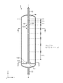
- FIG. 1 is a vertical cross-sectional side view of the gas conditioning apparatus 1
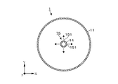
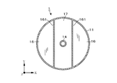
- FIGS. 2 and 3 are cross-sectional planes in which the gas conditioning apparatus 1 is viewed from the positions of AA ′ and BB ′ shown in FIG. 1.
- FIG. 1 is a vertical cross-sectional side view of the gas conditioning apparatus 1
- FIGS. 2 and 3 are cross-sectional planes in which the gas conditioning apparatus 1 is viewed from the positions of AA ′ and BB ′ shown in FIG. 1.
- FIG. 1 is a vertical cross-sectional side view of the gas conditioning apparatus 1
- FIGS. 2 and 3 are cross-sectional planes in which the gas conditioning apparatus 1 is viewed from the positions of AA ′ and BB ′ shown in FIG. 1.
- FIG. 1 is a vertical cross-sectional side view of the gas conditioning apparatus 1
- FIGS. 2 and 3 are cross-sectional planes in which the gas conditioning apparatus 1 is viewed from the positions of AA ′ and BB ′ shown in FIG. 1.
- the gas adjustment device 1 of this example is a gas when supplying the second gas having different properties (for example, the amount of heat of the fuel gas) from the first gas to the gas mixing vessel 11 in which the first gas is contained. It has a function of adjusting the state of mixture of gases so as to alleviate the sudden property change of the mixed gas extracted from the mixing container 11.
- the gas adjustment apparatus 1 includes a gas mixing vessel 11 in which gas mixing is performed, a gas supply pipe 12 for supplying a second gas, and the inside of the gas mixing vessel 11.
- the gas mixing vessel 11 of this example is configured as a cylindrical vessel whose upper and lower end faces are closed, and is vertically disposed with its central axis oriented in the direction of gravity (the Z-axis direction shown in FIG. 1). .
- the cylindrical container used as the gas mixing container 11 has a height in the range of several tens cm to a few tens m, and the ratio (L / D) of the height L to the diameter D of the cylinder is in the range 2 to 10 Can be illustrated.
- a gas supply pipe 12 to which plural types of gases are supplied is connected to an end surface (one end surface) on the upper side of the gas mixing container 11.
- a gas extraction pipe 13 for extracting the gas in the gas mixing container 11 is connected to an end surface (other end surface) on the bottom side of the gas mixing container 11.
- a cylindrical gas supply nozzle 14 consisting of an elongated straight pipe extends up and down along the direction of the central axis toward the inside of the gas mixing vessel 11. It is provided as.
- the diameter of the gas supply nozzle 14 is 1/3 or less of the diameter of the gas mixing vessel 11, and the length of the gas supply nozzle 14 is about 50 to 90% of the height of the gas mixing vessel 11.
- the proximal end side of the gas supply nozzle 14 is in communication with the gas supply pipe 12 and can receive the gas supplied from the gas supply nozzle 14.
- the end face on the tip end side of the gas supply nozzle 14 is closed.
- a gas supply hole 151 for supplying the gas flowing into the gas supply nozzle 14 through the gas supply pipe 12 into the gas mixing container 11 is formed on the side peripheral surface of the gas supply nozzle 14. As shown in FIG. 2, a plurality of gas supply holes 151 are formed in the gas supply nozzle 14 along the circumferential direction of the gas supply nozzle 14.
- a gas discharge unit 15 the above-described region in which the plurality of gas supply holes 151 are formed along the circumferential direction of the gas supply nozzle 14 is referred to as a gas discharge unit 15.
- gas supply nozzle 14 of the present example four gas supply holes 151 are arranged at equal intervals along the circumferential direction of the gas supply nozzle 14 in each gas discharge portion 15 The gas can be discharged in four directions toward the inner space of the mixing container 11.
- the interval H k may be set on the basis of other ideas.
- baffle plates 16 are provided between the extraction position. Each baffle plate 16 is directed in the direction intersecting the flow of gas flowing along the inner peripheral surface of the gas mixing vessel 11 (the direction along the XY plane shown in FIG. 1). It is provided to block part of the
- each baffle plate 16 sets two strings in parallel within the circular cross section of the gas mixing vessel 11 across the arrangement area of the gas supply nozzle 14, each chord And the inner peripheral surface of the gas mixing vessel 11 are closed. Therefore, the area sandwiched between the two strings is an open area 17 where the baffle plate is not provided.
- the baffle plate 16 when viewing the cross section of the gas mixing vessel 11 along the circumferential direction with the gas supply nozzle 14 as a center, the baffle plate 16 The provided area and the area where the baffle plate is not provided (opening area 17) are alternately arranged.
- a ridge-like projection 161 projects in a direction (upward direction) to stop the flow of gas flowing along the plate surface of the baffle plate 16 It is provided.
- the height of the ridge-like projections 161 is set to, for example, about several centimeters to several tens of centimeters.
- the tip (lower end) of the gas supply nozzle 14 is closer to the tip of the gas discharger 15 disposed on the most distal side. It extends downward and reaches the above-mentioned opening area 17. This is to facilitate the manufacture of the gas discharger 15 disposed at the forefront.
- extending the tip of the gas supply nozzle 14 to the position where the baffle plate 16 is disposed is not an essential requirement, and the gas supply at a position near the gas discharge unit 15 disposed on the above-described most distal end side The nozzle 14 may be terminated.
- the operation of the gas regulator 1 having the configuration described above will be described.
- the inside of the gas mixing container 11 is in a state in which the first gas is accommodated.
- the second gas is supplied from the gas supply pipe 12
- the second gas is discharged from the gas supply holes 151 formed in each gas discharge portion 15 of the gas supply nozzle 14 into the gas mixing container 11. Ru.
- the gas adjustment device 1 of the present example since the plurality of gas discharge portions 15 are discretely arranged along the extending direction of the gas supply nozzle 14 (axial direction of the gas mixing container 11), the first, A region in which the second gas mixture progresses is dispersed in the vicinity of each gas discharge unit 15. As a result, compared to the case where the second gas is supplied directly from the gas supply pipe 12 into the gas mixing vessel 11 without providing the gas supply nozzle 14 (comparative example 1-1 described later), the gas extraction is performed. The amount of property fluctuation per unit time of the gas extracted from the pipe 13 can be suppressed.
- the flow rate of the gas flowing around the gas discharger 15 increases toward the tip end side as compared with the base end side of the gas supply nozzle 14.
- the gas discharge parts 15 are arranged at equal intervals, for example, and no measures are taken, the flow velocity of the gas flowing around the gas discharge part 15 as it goes to the tip end side of the gas supply nozzle 14 Will rise.
- the gas in the gas mixing container 11 is extracted from the gas extraction pipe 13 while the mixing with the second gas discharged from the gas supply hole 151 of the gas discharge unit 15 does not proceed sufficiently. It becomes a state of blowout. Thereafter, when the second gas discharged into the gas mixing vessel 11 reaches the gas extraction pipe 13 without sufficiently advancing the mixing with the first gas, the concentration of the second gas becomes rapidly high. Therefore, the amount of property fluctuation per unit time becomes large.
- Each gas discharge part 15 is arrange
- FIGS. 4 and 5 schematically show the flow of the gas (second gas) discharged from the gas supply holes 151 of the gas discharge unit 15 disposed on the extreme end side.
- the flow of the gas discharged from the gas supply hole 151 is indicated by a broken arrow.
- the mixing with the gas in the gas mixing container 11 proceeds even during a period in which the second gas discharged from the gas supply hole 151 flows on the streamline indicated by the broken arrow. Therefore, compared with the proximal end of the broken arrow (the outlet of the gas supply hole 151), the mixing of the first and second gases is advanced at the distal end of the broken arrow.
- the gas discharged from the gas supply holes 151 flows radially outward in the gas mixing vessel 11, and is then positioned near the inner circumferential surface of the gas mixing vessel 11. Change the flow direction downward.
- the baffle plate 16 in the area
- the baffle plate 16 in only one stage between the arrangement position of the gas discharge portion 15 on the tip end side of the gas supply nozzle 14 and the extraction position of the gas to the gas extraction pipe 13, gas mixing While suppressing the increase in pressure loss in the container 11, the gas vortex shown in FIG. 4 can be formed to allow the gas mixing to proceed.
- the gas B which is the second gas is supplied from the gas supply nozzle 14 to the gas mixing container 11 in which the gas A is stored as the first gas, for example, by the action of the gas adjustment device 1 described above, the gas The concentration of the gas B in the gas extracted from the extraction pipe 13 is increased. At this time, since the rapid concentration change in the gas extracted from the gas extraction pipe 13 is suppressed by the actions of the gas supply nozzle 14 and the baffle plate 16 described above, the property fluctuation per unit time of the gas The amount can be kept small. Then, when the supply of the gas A from the gas supply nozzle 14 is continued, the concentration of the gas B in the gas mixing vessel 11 becomes close to 100% (1 in molar fraction), and the gas extracted from the gas extraction pipe 13 The properties of are stable.
- the gas B in the gas mixing vessel 11 corresponds to the first gas, and from the gas supply pipe 12
- the supplied gas corresponds to the second gas, and the mixing operation similar to the above-described example is performed.
- the gas regulator 1 According to the gas regulator 1 according to the present embodiment, the following effects can be obtained. Since the gas is supplied dispersed into the gas mixing vessel 11 from the elongated cylindrical gas supply nozzle 14 in which the plurality of gas discharge portions 15 are discretely arranged, the second gas for the first gas is supplied Mixing gradually progresses. Furthermore, since the baffle plate 16 is provided on the downstream side of the gas discharge unit 15 at the most distal end in the direction intersecting the flow of the gas flowing along the inner peripheral surface of the gas mixing vessel 11, as shown in FIG. As shown, it is possible to change the flow direction of the gas to advance the mixing of the gas, and to suppress the rapid property change of the gas extracted from the gas adjustment device 1.
- the gas containing the mist 21 may be either the first gas contained in the gas mixing container 11 or the second gas supplied into the gas mixing container 11 from the gas supply nozzle 14. It may be both.
- the baffle plate 16a of this example is formed so that the height position of the plate surface is gradually lowered from the inner peripheral surface side of the gas mixing vessel 11 toward the ridge-like protrusion 161 side, and has an inclined surface.
- the mist 21 which has flowed down the inside of the gas mixing vessel 11 according to the flow of gas collides with the baffle plate 16 a and is collected, becoming a liquid film-like liquid 22, It flows on the inclined surface of the plate 16a.
- An opening 172 for discharging the liquid 22 to the lower side of the baffle plate 16 a is formed in the ridge-like protrusion 161.
- a drain pipe 18 is connected to the bottom of the gas mixing container 11, and the liquid 22 dropped through the opening 172 is drained to the outside through the drain pipe 18.
- the gas extraction piping 13 is connected to the height position between the connection position of the drainage pipe 18 and the arrangement position of the baffle plate 16 a, and the gas separated from the liquid 22 is extracted from the gas mixing container 11 .
- the gas mixing vessel 11 of the gas conditioning apparatus is not limited to the case where the gas mixing vessel 11 is disposed vertically so that the axial direction coincides with the gravity direction.
- FIG. 7 shows an example of the gas conditioning apparatus 1a including the gas mixing vessel 11 which is horizontally disposed with the axial direction oriented in the horizontal direction.
- components common to those of the gas adjusting device 1 shown in FIGS. 1 to 6 are denoted by the same reference numerals as those used in these figures.
- the extending direction of the gas supply nozzle 14 is also the horizontal direction.
- the gas supply nozzle 14 may be supported by the support column 19 provided between the inner peripheral surface of the gas mixing container 11 as shown in FIG.
- the gas supply piping 12 connected to the gas supply nozzle 14 is not limited to the case where it is comprised by one piping connected to the end surface by the side of the upper part of the gas mixing container 11 like the example shown in FIG.
- the first gas supply pipe 12a for supplying the gas A and the second gas supply pipe 12b for supplying the gas B are joined at a position near the end face in the gas mixing vessel 11.
- the gas supply nozzle 14 may be connected to the downstream side of the gas supply pipes 12a and 12b.
- the arrangement interval (H k ) of the gas discharge unit 15 is from the proximal end side to the distal end side of the gas supply nozzle 14.
- interval of the gas discharge part 15 is not limited to this example.
- the gas discharge unit 15 may be arranged at intervals.
- the gas discharge portions 15 may be arranged at equal intervals, and other measures may be taken to suppress the occurrence of the blow through phenomenon.
- the opening diameter of the gas supply hole 151 is gradually reduced from the proximal end side to the distal end side of the gas supply nozzle 14 to increase the discharge flow rate of the second gas, and the gas mixing container 11 is formed.
- a conical gas mixing vessel 11 in which the radius of the cross section increases from the base end side to the tip end side of the gas supply nozzle 14 or a method for promoting the mixing with the gas inside the gas mixing vessel The method of suppressing the rise of the flow velocity accompanying the confluence of the gas flowing inside 11 and the second gas supplied from the gas supply nozzle 14 can be exemplified.
- FIG. 7 shows an example of the baffle plate 16 in which the installation of the hook-like protrusions 161 is omitted.
- the gas flows flowing inward in the radial direction of the gas mixing container 11 along the baffle plate 16 are in the central region of the gas mixing container 11 By merging, a change in the flow direction and the formation of a vortex occur, and the mixing with the gas in the gas mixing vessel 11 can be further advanced.
- the present invention may be applied to the adjustment device 1.
- the arrangement interval setting of the gas supply piping 12 and the gas discharge part 15 shown in FIG. 1, the baffle plate 16 provided with the ridge-like projection part 161 is applied to the gas adjustment device 1a of horizontal installation of FIG. Of course it is good.
- the number and arrangement of the gas supply holes 151 formed in each of the gas discharge portions 15 are not limited to the example shown in FIG. For example, by changing the formation direction of the gas supply holes 151 on the side surface of the gas supply nozzle 14 and forming the gas supply holes 151 one by one in each gas discharge portion 15, gas in different directions in each gas discharge portion 15 It may be configured to be discharged.
- a plurality of rows of gas supply holes 151 in which a plurality of gas supply holes 151 are arranged at equal intervals along the circumferential direction of the gas supply nozzle 14, may be arranged vertically.
- the plurality of gas supply holes 151 may be arranged in a spiral along the circumferential direction of the gas supply nozzle 14.
- the gas supply nozzle 14 may be configured using a spiral thin tube extending along the direction of the central axis of the gas mixing container 11.
- the planar shape of the opening area 17 formed between the baffle plates 16 is not limited to the example shown in FIG.
- an open area 17 extending in the X-axis direction in FIG. 3 may be added to form a cross-shaped open area 17, or more open areas 17 may be radially emitted from the center position of the cross section of the gas mixing vessel 11. (In these cases, the width of the opening area 17 is appropriately adjusted to secure the arrangement area of the baffle plate 16).
- the opening area 17 extends to the inner peripheral surface side of the gas mixing vessel 11, for example, the central area of the cross section of the gas mixing vessel 11 Only the circular opening area 17 may be provided.
- the gas flowing in the vicinity of the inner circumferential surface passes through the opening area 17 and reaches the gas extraction pipe 13 (FIG. 5) and is interrupted by the baffle plate 16 (FIG. 4)
- the action of forming the time lag of the gas reaching the gas extraction pipe 13 is reduced, the effect of promoting the mixing of the gas accompanying the provision of the baffle plate 16 is still exhibited.
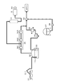
- FIG. 8 shows an example in which the vertically mounted gas regulator 1 is provided, but the configuration on the receiving facility side is the same even in the case where the horizontally mounted gas regulator 1a is provided.
- the receiving facility shown in FIG. 8 includes a gas engine 5 which is an internal combustion engine that uses as a fuel Boil Off Gas (BOG) generated in the LNG tank 32.
- the gas regulator 1 of this example is provided on the upstream side of the gas engine 5.
- the LNG stored in the LNG tank 32 is pumped from the LNG tank 32 by the LNG pump 33 and the delivery pump 35, vaporized by the LNG vaporizer 36, After adjusting the amount of heat for adding the LPG delivered from the LPG tank 37 by the LPG pump 38 in the adjustment unit 39, the adjustment unit 39 is shipped to the customer 4.
- BOG is generated by the vaporization of the LNG.
- BOG is boosted by a BOG compressor 34 having a plurality of compression stages 341 to 343 and then discharged to the customer 4 together with the vaporized LNG, or reliquefied and returned to the LNG tank 32.
- FIG. 8 shows an example in which BOG is discharged to the customer 4 together with the vaporized LNG).
- the LNG tank 32 receives the LNG from the LNG tanker 31 via the unloading arm 311. At this time, the amount of BOG generated in the LNG tank 32 may increase to several times the normal time.
- a gas engine 5 is provided using BOG as a fuel as a destination of use of surplus BOG, and the gas engine 5 can be driven to cause the generator 51 to generate power.
- the gas engine 5 may be provided with a restriction on the amount of heat quantity fluctuation per unit time of the fuel gas to be used.
- the heat quantity of BOG may change significantly. Therefore, as shown in FIG. 8, by providing the gas adjustment device 1 of the present example on the upstream side of the gas engine 5, it is possible to alleviate the variation in the amount of heat per unit time for BOG supplied to the gas engine 5.
- BOG stored in the gas adjustment device 1 before the change in heat of BOG occurs corresponds to the first gas, and the gas adjustment device 1 is generated according to the change in the amount of heat.
- the supplied BOG corresponds to the second gas.
- a pressure control valve for controlling the pressure in the gas mixing vessel 11 is provided downstream of the gas conditioning device 1, and the pressure in the gas mixing vessel 11 is increased or decreased to increase or decrease the amount of BOG contained in the gas mixing vessel 11. May be When the BOG generation amount in the LNG tank 32 increases and reaches the upper limit of the dispensable amount to the customer 4 and the possible supply amount of BOG to the gas engine 5, the BOG storage amount in the gas conditioning device 1 is temporarily It can also be used as a gas holder that absorbs excess BOG.
- the present invention is not limited to the case where BOG is used as the fuel gas, and the gas vaporized by the LNG vaporizer 36 or a gas received from the outside may be used as the fuel gas and supplied to the gas engine 5 to generate power.
- the gas conditioners 1 and 1a can be applied.
- the gas capable of alleviating the property change using the gas adjustment devices 1 and 1a is not limited to the fuel gas.
- the present invention can also be applied to the supply of gas to equipment and processes having a limited amount of property fluctuation per unit time, such as a change in the composition of the source gas supplied to the catalytic reaction.
- Simulation 1 Changes in properties and the like when the second gas was supplied to various spaces in which the first gas was stored were analyzed by CFD (Computational Fluid Dynamics).
- A. Simulation Conditions (Example) The first gas BOG (heat quantity (low calorific value, the same applies hereinafter): 29.8 MJ / Nm 3 ) is accommodated in the gas regulator 1 described with reference to FIGS. 1 to 3. Pipe 13 when the second gas city gas (heat quantity: 40.5 MJ / Nm 3 ) is supplied at 3,287 [Nm 3 / h] from the gas supply pipe 12 in the initial state.
- the gas mixing vessel 11 has a diameter of 3 [m], a volume of about 65 [m 3 ], and the gas supply nozzle 14 uses 150 A (outer diameter 165.2 [mm]) piping.
- the hole diameter of 151 is 15 mm, and the opening width (the width in the X direction in FIG. 3) of the opening area 17 formed between the baffle plates 16 is 237 mm.
- the software of CFD analysis used FLUENT (registered trademark) of ANSYS.
- Comparative Example 1-1 A simulation similar to that of the example was performed using the gas mixing vessel 11 in which the gas supply nozzle 14 and the baffle plate 16 were not provided. The diameter and volume of the gas mixing vessel 11 are the same as in the embodiment. Comparative Example 1-2 As shown in FIG. 9, the fuel gas is switched between the first supply pipe 61 for supplying BOG and the second supply pipe 62 for supplying city gas. The same simulation as that of the example was performed on the fuel gas at the outlet of the straight pipe 63 when switching of the fuel gas was performed for the straight pipe 63. The volume of the straight pipe 63 is 0.042 [m 3 ]
- FIG. 10 The concentration change of the city gas in the fuel gas and the time-dependent change of the calorific value according to the example and the comparative example 1-1 are shown in FIG. 10, and the same result according to the comparative example 1-2 is shown in FIG.
- the horizontal axis in FIGS. 10 and 11 indicates the elapsed time since the start of the city gas supply, and the vertical axis on the left side indicates the city gas concentration (molar fraction [ ⁇ ]).
- the vertical axis on the right side indicates the calorific value (low calorific value [MJ / Nm 3 ]) of the fuel gas at the outlet position.
- FIG. 12 the temporal change of the heat quantity fluctuation amount per unit time according to the example and the comparative example 1-1 is shown in FIG. 12, and the similar result according to the comparative example 1-2 is shown in FIG.
- the horizontal axis of FIGS. 12 and 13 indicates the elapsed time since the start of the city gas supply, and the vertical axis indicates the heat quantity fluctuation amount [MJ / Nm 3 / min] per unit time.
- Example and Comparative Example 1-1 the molar fraction of the city gas in the fuel gas on the outlet side rises to nearly 90% in about 15 minutes, and this molar fraction changes.
- the amount of heat of the fuel gas also gradually increased.
- the fuel gas on the outlet side was switched from BOG to city gas in an extremely short time of less than 0.01 minutes (0.6 seconds) (FIG. 11).
- the heat quantity fluctuation quantity per unit time is suppressed to 1.0 [MJ / Nm 3 / min] or less I was able to.
- this value exceeds the target value.
- Comparative Example 1-2 the heat quantity fluctuation amount per unit time has increased to several thousand times the target value.
- Simulation 2 CFD analysis was performed on the influence of the installation of the baffle plate 16 on the heat quantity fluctuation per unit time.
- A. Simulation Conditions (Comparative Example 2-1) In the case where the baffle plate 16 was not provided in the gas adjustment device 1 of Example 1, the same simulation as in Example 1 was performed to determine the maximum value of the heat quantity fluctuation amount per unit time. .
Landscapes
- Chemical & Material Sciences (AREA)
- Chemical Kinetics & Catalysis (AREA)
- Engineering & Computer Science (AREA)
- General Chemical & Material Sciences (AREA)
- Oil, Petroleum & Natural Gas (AREA)
- Combustion & Propulsion (AREA)
- Mechanical Engineering (AREA)
- General Engineering & Computer Science (AREA)
- Accessories For Mixers (AREA)
Abstract
【課題】第1の気体と第2の気体との混合に伴う性状変化の影響を緩和することが可能なガス調整装置を提供する。 【解決手段】第1の気体と第2の気体との混合状態を調整するガス調整装置1において、第1のガスが収容されたガス混合容器11には、第2の気体を供給するためのガス供給配管12と、ガス混合容器11から気体を抜き出すためのガス抜出配管13とが接続されている。ガス混合容器11内には、細長い筒状のガス供給ノズル14が設けられ、ガス供給孔151が形成された領域である複数のガス吐出部15が離散的に配置されている。ガス供給ノズル14の最先端部側のガス吐出部15の配置位置の下流側には、ガス混合容器11の横断面の一部を遮るようにバッフル板16が設けられている。
Description
本発明は、混合容器内の第1の気体に対し、第2の気体を混合する技術に関する。
ガスエンジンなどの内燃機関には、燃焼状態の変化に伴う排ガス性状の悪化や失火などを避けるため、使用する燃料ガスの単位時間あたりの熱量変動量に制約が設けられる場合がある。
この点に関して例えば特許文献1には、熱量が変動しやすい副燃料ガス(例えばバイオガス)に対し、熱量が安定している主燃料ガス(例えば都市ガス)の混合比率を変化させて、混合燃料ガスの熱量が目標値となるように調節する技術が記載されている。
しかしながら特許文献1に記載のように、複数種類の燃料ガスの混合比率を変化させて内燃機関に供給される燃料ガス(混合燃料ガス)の熱量の安定化を図る技術は、熱量の安定した燃料ガスの入手が困難な場合などには採用することができない。
また、内燃機関に供給される燃料ガスの熱量変化に限らず、触媒反応に供給される原料ガスの組成変化など、単位時間当たりの性状変動量に制限のある機器やプロセスも存在する。
本発明は、このような背景の下になされたものであり、その目的は、第1の気体と第2の気体との混合に伴う性状変化の影響を緩和することが可能なガス調整装置を提供することにある。
本発明のガス調整装置は、第1の気体と第2の気体との混合状態を調整するガス調整装置において、
端面が塞がれた筒状のガス混合容器と、
前記第1のガスが収容されたガス混合容器に対し、前記第2の気体を供給するためのガス供給配管と、
前記ガス供給配管に接続され、前記ガス混合容器の一方の端面側から、このガス混合容器の軸方向に沿って延在するように当該ガス混合容器内に設けられ、ガス供給孔が形成された領域である複数のガス吐出部が、前記延在方向に沿って離散的に配置された細長い筒状のガス供給ノズルと、
前記一方の端面と対向する他方の端面側から、前記ガス混合容器内の気体を抜き出すためのガス抜出配管と
前記ガス供給ノズルの最先端部側のガス吐出部の配置位置と、前記ガス混合容器内からガス抜出配管への気体の抜出位置との間に配置され、前記ガス混合容器の内周面に沿って流れる気体の流れと交差する方向に向けて、当該ガス混合容器の横断面の一部を遮るように設けられたバッフル板と、を備えていることを特徴とする。
端面が塞がれた筒状のガス混合容器と、
前記第1のガスが収容されたガス混合容器に対し、前記第2の気体を供給するためのガス供給配管と、
前記ガス供給配管に接続され、前記ガス混合容器の一方の端面側から、このガス混合容器の軸方向に沿って延在するように当該ガス混合容器内に設けられ、ガス供給孔が形成された領域である複数のガス吐出部が、前記延在方向に沿って離散的に配置された細長い筒状のガス供給ノズルと、
前記一方の端面と対向する他方の端面側から、前記ガス混合容器内の気体を抜き出すためのガス抜出配管と
前記ガス供給ノズルの最先端部側のガス吐出部の配置位置と、前記ガス混合容器内からガス抜出配管への気体の抜出位置との間に配置され、前記ガス混合容器の内周面に沿って流れる気体の流れと交差する方向に向けて、当該ガス混合容器の横断面の一部を遮るように設けられたバッフル板と、を備えていることを特徴とする。
前記ガス調整装置は以下の特徴を備えていてもよい。
(a)前記複数のガス吐出部は、各々、前記ガス供給ノズルの周方向に沿って複数のガス供給孔が形成されると共に、前記ガス供給ノズルの基端部側から先端部側へ向けて、隣り合うガス吐出部同士の間隔が次第に大きくなるように配置されていること。
(b)前記ガス混合容器の横断面を見たとき、前記バッフル板が設けられた領域と、バッフル板が設けられていない領域とが前記横断面の周方向に沿って交互に配置されるように、複数枚のバッフル板が設けられていること。
(c)前記バッフル板の端部には、当該バッフル板によって遮られた後、このバッフル板の板面に沿って流れる気体を堰き止める方向へ突出するように形成された堰状突起部が設けられていること。
(d)(c)において、前記第1の気体と第2の気体との少なくとも一方にはミストが含まれていることと、前記ガス混合容器は、前記ガス供給ノズルの基端部側が先端部側よりも上方に位置するように、前記軸方向を重力方向に向けて配置されていることと、前記バッフル板は、前記ガス混合容器の内周面側から堰状突起部側に向けて板面の高さ位置が次第に低くなるように形成されると共に、前記堰状突起部には前記ミストがバッフル板に衝突して捕集された液体を下方側へ排出するための開口部が形成されていることと、前記ガス混合容器の底部である前記他方の端面には、前記開口部を介して落下した液体を排出するための排液管が接続され、前記ガス抜出配管は、前記排液管の接続位置とバッフル板との間の高さ位置から気体を抜き出すように設けられていること。
(e)前記第1の気体及び第2の気体は発熱量が異なる燃料ガスであり、前記ガス抜出配管の下流側には、前記燃料ガスを燃料とする内燃機関が設けられていること。このとき、第1の気体及び第2の気体である前記燃料ガスは、液化天然ガスを貯蔵する貯蔵タンク内で発生したボイルオフガスであること。
(a)前記複数のガス吐出部は、各々、前記ガス供給ノズルの周方向に沿って複数のガス供給孔が形成されると共に、前記ガス供給ノズルの基端部側から先端部側へ向けて、隣り合うガス吐出部同士の間隔が次第に大きくなるように配置されていること。
(b)前記ガス混合容器の横断面を見たとき、前記バッフル板が設けられた領域と、バッフル板が設けられていない領域とが前記横断面の周方向に沿って交互に配置されるように、複数枚のバッフル板が設けられていること。
(c)前記バッフル板の端部には、当該バッフル板によって遮られた後、このバッフル板の板面に沿って流れる気体を堰き止める方向へ突出するように形成された堰状突起部が設けられていること。
(d)(c)において、前記第1の気体と第2の気体との少なくとも一方にはミストが含まれていることと、前記ガス混合容器は、前記ガス供給ノズルの基端部側が先端部側よりも上方に位置するように、前記軸方向を重力方向に向けて配置されていることと、前記バッフル板は、前記ガス混合容器の内周面側から堰状突起部側に向けて板面の高さ位置が次第に低くなるように形成されると共に、前記堰状突起部には前記ミストがバッフル板に衝突して捕集された液体を下方側へ排出するための開口部が形成されていることと、前記ガス混合容器の底部である前記他方の端面には、前記開口部を介して落下した液体を排出するための排液管が接続され、前記ガス抜出配管は、前記排液管の接続位置とバッフル板との間の高さ位置から気体を抜き出すように設けられていること。
(e)前記第1の気体及び第2の気体は発熱量が異なる燃料ガスであり、前記ガス抜出配管の下流側には、前記燃料ガスを燃料とする内燃機関が設けられていること。このとき、第1の気体及び第2の気体である前記燃料ガスは、液化天然ガスを貯蔵する貯蔵タンク内で発生したボイルオフガスであること。
本発明は、複数のガス吐出部が離散的に配置された細長い筒状のガス供給ノズルから、混合容器内に向けて分散してガスが供給されるので、第1の気体に対する第2の気体の混合が徐々に進行する。さらに、ガス吐出部の下流側には、前記ガス混合容器の内周面に沿って流れる気体の流れと交差する方向に向けてバッフル板が設けられているので気体の流れ方向を変えて気体の混合を進行させ、ガス調整装置から抜き出される気体の急激な性状変化を抑えることができる。
図1~図3を参照しながら、本発明の実施の形態に係るガス調整装置1の構成について説明する。図1はガス調整装置1の縦断側面図であり、図2、図3は、各々、図1に示すA-A’、B-B’の位置から当該ガス調整装置1を矢視した横断平面図である。
本例のガス調整装置1は、第1の気体が収容されたガス混合容器11に対し、第1の気体とは性状(例えば燃料ガスの熱量)の異なる第2の気体を供給したとき、ガス混合容器11から抜き出される混合気体の急激な性状変化が緩和されるように気体の混合状態を調整する機能を備える。
図1~図3に示すように、前記ガス調整装置1は、気体の混合が行われるガス混合容器11と、第2の気体を供給するためのガス供給配管12と、ガス混合容器11内へ第2の気体を吐出するガス供給ノズル14と、ガス混合容器11から抜き出される気体の性状を調整するためのバッフル板16と、ガス混合容器11内の気体を抜き出すためのガス抜出配管13とを備えている。
本例のガス混合容器11は、上下両端面が塞がれた円筒状の容器として構成され、その中心軸を重力方向(図1に示すZ軸方向)に向けて縦置きに配置されている。ガス混合容器11として用いられる円筒状容器としては、高さが数十cm~十数mの範囲、円筒の高さLと直径Dとの比(L/D)が2~10の範囲のものを例示することができる。
例えば、ガス混合容器11の上部側の端面(一方の端面)には、複数種類の気体が供給されるガス供給配管12が接続されている。また、ガス混合容器11の底部側の端面(他方の端面)には、ガス混合容器11内の気体を抜き出すためのガス抜出配管13が接続されている。
ガス混合容器11に対するガス供給配管12の接続位置からは、ガス混合容器11内に向けて、細長い直管からなる円筒状のガス供給ノズル14が前記中心軸の方向に沿って上下に延在するように設けられている。例えばガス供給ノズル14の直径は、ガス混合容器11の直径の1/3以下、ガス供給ノズル14の長さはガス混合容器11の高さの50~90%程度のものが用いられる。ガス供給ノズル14の基端部側はガス供給配管12に連通し、ガス供給ノズル14から供給される気体を受け入れることができる。一方で、ガス供給ノズル14の先端部側の端面は塞がれている。
ガス供給ノズル14の側周面には、ガス供給配管12を介してガス供給ノズル14内に流入した気体をガス混合容器11内に供給するためのガス供給孔151が形成されている。図2に示すようにガス供給ノズル14には、ガス供給ノズル14の周方向に沿って複数のガス供給孔151が形成されている。
以下、複数のガス供給孔151がガス供給ノズル14の周方向に沿って形成されている上述の領域をガス吐出部15と呼ぶ。
以下、複数のガス供給孔151がガス供給ノズル14の周方向に沿って形成されている上述の領域をガス吐出部15と呼ぶ。
例えば本例のガス供給ノズル14において、各ガス吐出部15には4つのガス供給孔151がガス供給ノズル14の周方向に沿って等間隔に配置され、ガス供給ノズル14の側周面からガス混合容器11の内部空間へ向け、四方に気体を吐出することができる。
図1に示すように、ガス供給ノズル14には、ガス供給ノズル14の延在方向に沿って、複数のガス吐出部15が離散的に(互いに間隔を開けて)配置されている。そして、これら複数のガス吐出部15は、ガス供給ノズル14の基端部(ガス供給配管12との接続部)側から先端部側へ向けて、隣り合うガス吐出部15同士の間隔(Hk)が次第に大きくなる(Hk-1<Hk(但し、k=2、3、…、n))ように配置されている。
前記間隔Hkの設定手法は、例えば等差的(Hk-1-Hk=a、例えばaは0.2H1~5H1)に間隔Hkを大きくしていってもよいし、等比的(Hk/Hk-1=r、例えばrは1.1~2.0)に間隔Hkを大きくしていってもよい。また、その他の考え方に基づいて間隔Hkの設定を行ってもよいことは勿論である。
さらに図1に示すように、ガス混合容器11内には、ガス供給ノズル14の最先端部側に配置されたガス吐出部15と、ガス混合容器11内からガス抜出配管13への気体の抜出位置との間に2枚のバッフル板16が設けられている。各バッフル板16は、ガス混合容器11の内周面に沿って流れる気体の流れと交差する方向(図1に示すX-Y面に沿った方向)に向けて、ガス混合容器11の横断面の一部を遮るように設けられている。
図3の横断平面図に示すように、各バッフル板16は、ガス混合容器11の円形横断面内にガス供給ノズル14の配置領域を挟んで平行に2本の弦を設定したとき、各弦とガス混合容器11の内周面とに囲まれる領域を塞ぐように設けられている。よって前記2本の弦に挟まれた領域は、バッフル板が設けられていない開口領域17となっている。
上述のバッフル板16と開口領域17との配置の状態を言い替えると、ガス供給ノズル14を中心として、ガス混合容器11の横断面を周方向に沿って移動しながら見たとき、バッフル板16が設けられた領域と、バッフル板が設けられていない領域(開口領域17)とが交互に配置されている。
上述の弦の位置に相当する各バッフル板16の端部には、バッフル板16の板面に沿って流れる気体の流れを堰き止める方向(上方向)へ突出するように堰状突起部161が設けられている。堰状突起部161の高さは、例えば数cm~数十cm程度に設定される。
ここで、本例のガス調整装置1において、図1、図3などに示すように、ガス供給ノズル14の先端部(下端部)は、最先端部側に配置されたガス吐出部15よりも下方側に伸び出し、上述の開口領域17に到達している。これは最先端部に配置されたガス吐出部15の製作を容易にするためである。但し、ガス供給ノズル14の先端部をバッフル板16が配置されている位置まで伸ばすことは必須の要件ではなく、上述の最先端部側に配置されたガス吐出部15の近傍位置にてガス供給ノズル14を終端させてもよい。
以上に説明した構成を備えたガス調整装置1の作用について説明する。
はじめに、ガス混合容器11内は第1の気体が収容された状態となっている。次いで、ガス供給配管12から第2の気体を供給すると、ガス供給ノズル14の各ガス吐出部15に形成されているガス供給孔151からガス混合容器11内へ向けて第2の気体が吐出される。
はじめに、ガス混合容器11内は第1の気体が収容された状態となっている。次いで、ガス供給配管12から第2の気体を供給すると、ガス供給ノズル14の各ガス吐出部15に形成されているガス供給孔151からガス混合容器11内へ向けて第2の気体が吐出される。
本例のガス調整装置1においては、ガス供給ノズル14の延在方向(ガス混合容器11の軸方向)に沿って、複数のガス吐出部15が離散的に配置されているので、第1、第2の気体の混合が進行する領域が、各ガス吐出部15の近傍に分散される。この結果、ガス供給ノズル14を設けずに、ガス供給配管12から直接、ガス混合容器11内に第2の気体を供給する場合(後述の比較例1-1)と比較して、ガス抜出配管13から抜き出される気体の単位時間当たりの性状変動量を抑制することができる。
ここで例えば基端部側から数えてk段目に設けられているガス吐出部15に着目すると、当該領域においては、k段目のガス吐出部15に設けられているガス供給孔151から吐出される気体と、ガス混合容器11内の上流側から流れ込んでくる気体(1段目~(k-1)段目のガス吐出部15にて供給された気体)とが合流する。
従って、ガス供給ノズル14の基端部側と比較して、先端部側へ行くほどガス吐出部15の周囲を流れる気体の流量が増加することになる。この場合に、複数のガス吐出部15を例えば等間隔で配置し、且つ、何らの対策も行わないと、ガス供給ノズル14の先端部側へ行くほどガス吐出部15の周囲を流れる気体の流速が上昇する。この結果、当該ガス吐出部15のガス供給孔151から吐出された第2の気体との混合が十分に進行しないまま、ガス混合容器11内の気体がガス抜出配管13から抜き出される、いわば吹き抜けの状態となってしまう。その後、ガス混合容器11内に吐出された第2の気体が、第1の気体との混合が十分に進行しないままガス抜出配管13へ到達すると、第2の気体の濃度が急激に高くなって、単位時間当たりの性状変動量が大きくなってしまう。
このような吹き抜けの発生を抑制するため、本例のガス調整装置1においては、ガス供給ノズル14の基端部側から先端部側へ向けて、隣り合うガス吐出部15同士の間隔(Hk)が次第に大きくなるように各ガス吐出部15を配置している。この結果、ガス供給孔151から供給された気体(第2の気体)と、ガス混合容器11の上流側から流れてきた気体(第1の気体や、第1の気体と第2の気体との混合気体)との十分な混合時間が確保される。そして、ガス抜出配管13には各ガス吐出部15の近傍領域にて第1の気体と第2の気体とが十分に混合された状態の気体が到達するので、上述の吹き抜けに起因する単位時間当たりの性状変動量の増大を抑制することができる。
次いで図4、図5を参照しながらバッフル板16の作用について説明する。これらの図は、最先端部側に配置されたガス吐出部15のガス供給孔151から吐出された気体(第2の気体)の流れを模式的に示している。図4、図5中、ガス供給孔151から吐出された気体の流れは破線の矢印で示してある。なお、ガス供給孔151から吐出された第2の気体が、破線の矢印で示した流線上を流れる期間中においてもガス混合容器11内の気体のとの混合は進行する。従って、破線の矢印の基端部(ガス供給孔151の出口)と比較して、破線の矢印の先端部では、第1、第2の気体の混合が進行した状態となっている。
図4、図5に示すように、各ガス供給孔151から吐出された気体は、ガス混合容器11内を径方向外側へ向けて流れた後、ガス混合容器11の内周面の近傍位置にて、流れ方向を下方側へ変化させる。
そして図4に示すように、バッフル板16が設けられている領域では、ガス混合容器11の内周面に沿った前記気体の流れと交差する方向に向けてバッフル板16が配置されているので、気体はこれらバッフル板16の上面に沿って、ガス混合容器11の径方向内側へ向けて流れる。しかる後、堰状突起部161に到達した気体は、当該堰状突起部161に案内されてその流れ方向を上方へ向けて変化させる。この結果、図4に破線の矢印で示すように、ガス混合容器11内へ流れ込んだ気体の渦が形成されて、ガス混合容器11内の気体との混合がさらに進行する。
そして図4に示すように、バッフル板16が設けられている領域では、ガス混合容器11の内周面に沿った前記気体の流れと交差する方向に向けてバッフル板16が配置されているので、気体はこれらバッフル板16の上面に沿って、ガス混合容器11の径方向内側へ向けて流れる。しかる後、堰状突起部161に到達した気体は、当該堰状突起部161に案内されてその流れ方向を上方へ向けて変化させる。この結果、図4に破線の矢印で示すように、ガス混合容器11内へ流れ込んだ気体の渦が形成されて、ガス混合容器11内の気体との混合がさらに進行する。
一方で図5に示すように、バッフル板16が設けられていない開口領域17においては、ガス混合容器11の内周面に沿った前記気体の流れが開口領域17を通過してガス抜出配管13に到達して外部へ抜き出される。図5に示す流線に乗って流れる第2の気体と、ガス混合容器11内の気体との混合の進行度合いは、図4の場合と比較すると小さい。
このように、図4、図5に示す気体の流れが混在していることにより、開口領域17を通過してガス抜出配管13に到達する気体と、バッフル板16や堰状突起部161に流れを遮られて渦を形成した後、ガス抜出配管13に到達する気体との間に時間差が形成される。この結果、ガス供給孔151から吐出された気体の流れが同時にガス抜出配管13に到達する場合と比べて、急激な性状変化を抑制することができる。
また、ガス供給ノズル14の最先端部側のガス吐出部15の配置位置と、ガス抜出配管13への気体の抜出位置との間に1段だけバッフル板16を設けることにより、ガス混合容器11における圧力損失の増大を抑えつつ、図4に示す気体の渦を形成して、気体の混合を進行させることができる。
以上に説明したガス調整装置1の作用により、例えば第1の気体として気体Aが収容されているガス混合容器11に対し、ガス供給ノズル14より第2の気体である気体Bを供給すると、ガス抜出配管13から抜き出される気体中の気体Bの濃度が上昇する。このとき、既述のガス供給ノズル14やバッフル板16の作用により、ガス抜出配管13から抜き出される気体中の急激な濃度変化が抑えられているので、当該気体の単位時間当たりの性状変動量が小さく抑えられる。そして、ガス供給ノズル14からの気体Aの供給を継続すると、ガス混合容器11内の気体Bの濃度が100%(モル分率で1)近くになり、ガス抜出配管13から抜き出される気体の性状は安定する。
その後、ガス供給配管12から再び気体Aを供給したり、別の気体Cを供給したりする場合には、ガス混合容器11内の気体Bが第1の気体に相当し、ガス供給配管12から供給される気体が第2の気体に相当することとなり、上述の例と同様の混合操作が実施される。
その後、ガス供給配管12から再び気体Aを供給したり、別の気体Cを供給したりする場合には、ガス混合容器11内の気体Bが第1の気体に相当し、ガス供給配管12から供給される気体が第2の気体に相当することとなり、上述の例と同様の混合操作が実施される。
本実施の形態に係るガス調整装置1によれば以下の効果がある。複数のガス吐出部15が離散的に配置された細長い筒状のガス供給ノズル14から、ガス混合容器11内に向けて分散してガスが供給されるので、第1の気体に対する第2の気体の混合が徐々に進行する。さらに、最先端のガス吐出部15の下流側には、ガス混合容器11の内周面に沿って流れる気体の流れと交差する方向に向けてバッフル板16が設けられているので、図4に示すように気体の流れ方向を変えて気体の混合を進行させ、ガス調整装置1から抜き出される気体の急激な性状変化を抑えることができる。
次に、図6を参照しながら、ミスト21を含む気体を処理する場合に好適なバッフル板16aの設置例について説明する。ミスト21を含む気体は、ガス混合容器11に収容されている第1の気体、ガス供給ノズル14からガス混合容器11内に供給される第2の気体のいずれか一方であってもよいし、双方であってもよい。
本例のバッフル板16aは、ガス混合容器11の内周面側から堰状突起部161側に向けて板面の高さ位置が次第に低くなるように形成され、傾斜面を有している。この結果、気体の流れに乗ってガス混合容器11内を流下してきたミスト21は、バッフル板16aに衝突して捕集され、液膜状の液体22となり、堰状突起部161へ向けてバッフル板16aの傾斜面を流れる。
堰状突起部161には、バッフル板16aの下方側へ液体22を排出するための開口部172が形成されている。ガス混合容器11の底部には排液管18が接続され、開口部172を介して落下した液体22は、当該排液管18を介して外部へ排出される。一方、ガス抜出配管13は、排液管18の接続位置とバッフル板16aの配置位置との間の高さ位置に接続され、液体22と分離された気体がガス混合容器11から抜き出される。
また、ガス調整装置のガス混合容器11は、その軸方向が重力方向と一致するように縦置きに配置される場合に限定されない。図7には、軸方向を水平方向に向け、横置きに配置されたガス混合容器11を備えるガス調整装置1aの例を示してある。図8において、図1~図6に示したガス調整装置1と共通の構成要素には、これらの図で用いたものと共通の符号を付してある。
図7に示すように、ガス混合容器11が横置きに配置されている場合には、ガス供給ノズル14が延在する方向も水平方向となる。このとき、自重による撓みの発生を抑えるため、図7に示すようにガス混合容器11の内周面との間に設けた支柱部19により、ガス供給ノズル14を支持してもよい。
さらに図7のガス調整装置1aには、図1~図3に示したガス供給配管12、ガス供給ノズル14、バッフル板16の変形例も併せて示してある。
ガス供給ノズル14に接続されるガス供給配管12は、図1に示した例のように、ガス混合容器11の上部側の端面に接続された1本の配管により構成する場合に限定されない。例えば図7に示すように、気体Aの供給を行う第1のガス供給配管12aと、気体Bの供給を行う第2のガス供給配管12bとをガス混合容器11内の前記端面近傍位置で合流させ、これらのガス供給配管12a、12bの下流側にガス供給ノズル14を接続してもよい。
ガス供給ノズル14に接続されるガス供給配管12は、図1に示した例のように、ガス混合容器11の上部側の端面に接続された1本の配管により構成する場合に限定されない。例えば図7に示すように、気体Aの供給を行う第1のガス供給配管12aと、気体Bの供給を行う第2のガス供給配管12bとをガス混合容器11内の前記端面近傍位置で合流させ、これらのガス供給配管12a、12bの下流側にガス供給ノズル14を接続してもよい。
また、図1~図3を用いて説明したガス調整装置1の例においては、ガス吐出部15の配置間隔(Hk)が、ガス供給ノズル14の基端部側から先端部側へ向けて次第に大きくなるように設定されていることにより、ガス混合容器11内の気体の流量増大に伴う吹き抜け現象の発生を抑制している。
但し、ガス吐出部15の配置間隔の設定手法はこの例に限定されるものではない。例えば図7には、複数のガス吐出部15が等間隔(Hk=一定(但し、k=1、2、3、…、n))で配置されているガス供給ノズル14の例を示している。
但し、ガス吐出部15の配置間隔の設定手法はこの例に限定されるものではない。例えば図7には、複数のガス吐出部15が等間隔(Hk=一定(但し、k=1、2、3、…、n))で配置されているガス供給ノズル14の例を示している。
例えば、ガス供給ノズル14への第2の気体の供給流量が少なく、吹き抜け現象が問題となる程度にガス吐出部15の周囲を流れる気体の流速が上昇しない場合には、ガス吐出部15を等間隔で配置してもよい。また、ガス吐出部15を等間隔で配置すると共に、吹き抜け現象の発生を抑制するため他の対策を講じてもよい。他の対策としては、ガス供給ノズル14の基端部側から先端部側へ向けて次第にガス供給孔151の開口径を小さくして、第2の気体の吐出流速を高くし、ガス混合容器11内の気体との混合を促進する手法や、ガス供給ノズル14の基端部側から先端部側へ向けて、横断面の半径が大きくなる円錐型のガス混合容器11を利用し、ガス混合容器11内を流れる気体とガス供給ノズル14から供給される第2の気体との合流に伴う流速の上昇を抑制する手法を例示することができる。
さらに図7には堰状突起部161の設置を省略したバッフル板16の例を記載してある。堰状突起部161が設けられていないバッフル板16を設ける場合でも、バッフル板16に沿って、ガス混合容器11の径方向内側へ向けて流れる気体の流れ同士がガス混合容器11の中央領域で合流することにより、流れ方向の変化や渦の形成が生じ、ガス混合容器11内の気体との混合をさらに進行させることができる。
以上、図7に示した第1、第2のガス供給配管12a、12bやガス吐出部15の等間隔配置、堰状突起部161を備えないバッフル板16は、図1に示す縦置きのガス調整装置1に適用してもよい。これとは反対に、図1に示すガス供給配管12やガス吐出部15の配置間隔設定、堰状突起部161を備えたバッフル板16を、図7の横置きのガス調整装置1aに適用してよいことも勿論である。
図1~図6に示すガス調整装置1や、図7に示すガス調整装置1aに適用可能な機器のバリエーションをさらに挙げておく。
各ガス吐出部15に形成されるガス供給孔151の数や配置は、図2に示した例に限定されるものではない。例えばガス供給ノズル14の側面のガス供給孔151の形成方向を変化させながら、各ガス吐出部15に1つずつガス供給孔151を形成することにより、各ガス吐出部15にて異なる方向に気体が吐出される構成としてもよい。この他、各ガス吐出部15内において、ガス供給ノズル14の周方向に沿って複数のガス供給孔151が等間隔に配置されてなるガス供給孔151の列を、上下に複数列並べてもよい。また、各ガス吐出部15において、複数のガス供給孔151をガス供給ノズル14の周方向に沿って螺旋状に配置してもよい。
各ガス吐出部15に形成されるガス供給孔151の数や配置は、図2に示した例に限定されるものではない。例えばガス供給ノズル14の側面のガス供給孔151の形成方向を変化させながら、各ガス吐出部15に1つずつガス供給孔151を形成することにより、各ガス吐出部15にて異なる方向に気体が吐出される構成としてもよい。この他、各ガス吐出部15内において、ガス供給ノズル14の周方向に沿って複数のガス供給孔151が等間隔に配置されてなるガス供給孔151の列を、上下に複数列並べてもよい。また、各ガス吐出部15において、複数のガス供給孔151をガス供給ノズル14の周方向に沿って螺旋状に配置してもよい。
次いでガス供給ノズル14の構成についても直管によりガス供給ノズル14を構成することは必須の要件ではない。例えば、ガス混合容器11の中心軸の方向に沿って延在する螺旋状の細管を用いてガス供給ノズル14を構成してもよい。
バッフル板16の間に形成される開口領域17の平面形状についても図3に示した例に限定されるものではない。例えば図3のX軸方向に伸びる開口領域17を追加して、十字型の開口領域17を形成してもよいし、さらに多くの開口領域17をガス混合容器11の横断面の中心位置から放射状に延びるように設けてもよい(これらの場合において、バッフル板16の配置領域を確保するため、開口領域17の幅は、適宜、調整される)。
さらに図3、図5に示した例の如く、開口領域17は、ガス混合容器11の内周面側まで開口が広がっていることも必須ではなく、例えばガス混合容器11の横断面の中央領域のみに円形の開口領域17を設けてもよい。この場合には、内周面近傍を流れる気体が、開口領域17を通過してガス抜出配管13に到達する場合(図5)と、バッフル板16に遮られる場合(図4)とで、ガス抜出配管13に到達する気体の時間差を形成する作用は減殺されるが、バッフル板16を設けることに伴う気体の混合の促進効果は依然として発揮される。
次いで、図1~図7を用いて説明したガス調整装置1、1aの適用例につき、液化天然ガス(LNG:Liquefied Natural Gas)の受入設備の例を挙げて説明する。図示の便宜上、図8には縦置き型のガス調整装置1を設けた例を示してあるが、横置き型のガス調整装置1aを設ける場合であっても受入設備側の構成は同様である。
図8に示す受入設備は、LNGタンク32内で発生するボイルオフガス(BOG:Boil Off Gas)を燃料とする内燃機関であるガスエンジン5を備える。本例のガス調整装置1は、当該ガスエンジン5の上流側に設けられている。
図8に示す受入設備は、LNGタンク32内で発生するボイルオフガス(BOG:Boil Off Gas)を燃料とする内燃機関であるガスエンジン5を備える。本例のガス調整装置1は、当該ガスエンジン5の上流側に設けられている。
LNGの受入設備の構成について簡単に説明しておくと、LNGタンク32に貯蔵されたLNGは、LNGポンプ33、送出ポンプ35によりLNGタンク32から送り出され、LNG気化器36にて気化され、熱量調整部39にて、LPGポンプ38によりLPGタンク37から送り出されたLPGを添加する熱量調整が行われた後、需要先4へと出荷される。
LNGタンク32内においては、LNGの気化によりBOGが発生する。通常、BOGは、複数の圧縮段341~343を備えるBOG圧縮機34にて昇圧された後、気化されたLNGと共に需要先4へ払い出されたり、再液化されてLNGタンク32に戻されたりする(図8には、気化されたLNGと共にBOGが需要先4へ払い出される例を示してある)。
一方、LNGタンク32に対しては、アンローディングアーム311を介してLNGタンカー31からのLNGの受け入れが行われる。このとき、LNGタンク32にて発生するBOGの量が通常時の数倍にまで増大することがある。本例の受入設備には、余剰なBOGの利用先としてBOGを燃料としてガスエンジン5が設けられ、このガスエンジン5を駆動して発電機51にて発電を行うことができる。
ここでガスエンジン5は、利用する燃料ガスの単位時間当たりの熱量変動量に制約が設けられている場合がある。一方で、性状の異なるLNGを受け入れた際には、BOGの熱量が大きく変化する場合もある。
そこで図8に示すようにガスエンジン5の上流側に本例のガス調整装置1を設けることにより、ガスエンジン5に供給されるBOGについての単位時間当たりの熱量変動を緩和することができる。図8に示す適用例において、BOGの熱量変化が発生する前にガス調整装置1内に収容されていたBOGが第1の気体に相当し、前記熱量変化の発生に伴ってガス調整装置1に供給されるBOGが第2の気体に相当する。
そこで図8に示すようにガスエンジン5の上流側に本例のガス調整装置1を設けることにより、ガスエンジン5に供給されるBOGについての単位時間当たりの熱量変動を緩和することができる。図8に示す適用例において、BOGの熱量変化が発生する前にガス調整装置1内に収容されていたBOGが第1の気体に相当し、前記熱量変化の発生に伴ってガス調整装置1に供給されるBOGが第2の気体に相当する。
なお、ガス調整装置1の下流側にガス混合容器11内の圧力を調節する圧力調節弁を設け、ガス混合容器11内の圧力増減により、ガス混合容器11に収容されるBOGの量を増減してもよい。LNGタンク32におけるBOGの発生量が増大し、需要先4への払出し可能量やガスエンジン5へのBOGの供給可能量の上限に達したとき、ガス調整装置1におけるBOGの収容量を一時的に増やして、BOGの余剰量を吸収するガスホルダーとしても利用することができる。
また、BOGを燃料ガスとする場合に限らず、LNG気化器36で気化されたガスや外部から受け入れたガスを燃料ガスとし、ガスエンジン5に供給して発電を行う場合にも、本例のガス調整装置1、1aを適用することができる。
さらには、ガス調整装置1、1aを用いて性状変化を緩和することが可能な気体は燃料ガスに限定されるものではない。例えば触媒反応に供給される原料ガスの組成変化など、単位時間当たりの性状変動量に制限のある機器やプロセスへの気体の供給にも適用することができる。
さらには、ガス調整装置1、1aを用いて性状変化を緩和することが可能な気体は燃料ガスに限定されるものではない。例えば触媒反応に供給される原料ガスの組成変化など、単位時間当たりの性状変動量に制限のある機器やプロセスへの気体の供給にも適用することができる。
(シミュレーション1)
第1の気体が収容された種々の空間に対し、第2の気体を供給したときの性状変化などをCFD(Computational Fluid Dynamics)により解析した。
A.シミュレーション条件
(実施例)図1~図3を用いて説明したガス調整装置1について、第1の気体であるBOG(熱量(低発熱量、以下同じ):29.8MJ/Nm3)が収容された状態を初期状態として、ガス供給配管12から第2の気体である都市ガス(熱量:40.5MJ/Nm3)を3,287[Nm3/h]で供給したときのガス抜出配管13から抜き出される燃料ガス中の都市ガス濃度(モル分率)、発熱量[MJ/Nm3]、単位時間当たりの熱量変動量[MJ/Nm3/min]の経時変化を求めた。ガス混合容器11の直径は3[m]、容積は約65[m3]、ガス供給ノズル14は150A(外径165.2[mm])配管を用い、各ガス吐出部15におけるガス供給孔151の孔径はφ15[mm]であり、バッフル板16の間に形成された開口領域17の開口幅(図3のX方向の幅)は237[mm]である。CFD解析のソフトウェアは、ANSYS社のFLUENT(登録商標)を用いた。
(比較例1-1)ガス供給ノズル14及びバッフル板16が設けられていないガス混合容器11を用い、実施例と同様のシミュレーションを行った。ガス混合容器11の直径及び容積は実施例と同様である。
(比較例1-2)図9に示すように、BOGの供給を行う第1の供給管61と、都市ガスの供給を行う第2の供給管62との間で燃料ガスの切り替えが行われる直管63について、燃料ガスの切り替えが実施されたときの直管63の出口の燃料ガスに関し、実施例と同様のシミュレーションを行った。直管63の容積は0.042[m3]である
第1の気体が収容された種々の空間に対し、第2の気体を供給したときの性状変化などをCFD(Computational Fluid Dynamics)により解析した。
A.シミュレーション条件
(実施例)図1~図3を用いて説明したガス調整装置1について、第1の気体であるBOG(熱量(低発熱量、以下同じ):29.8MJ/Nm3)が収容された状態を初期状態として、ガス供給配管12から第2の気体である都市ガス(熱量:40.5MJ/Nm3)を3,287[Nm3/h]で供給したときのガス抜出配管13から抜き出される燃料ガス中の都市ガス濃度(モル分率)、発熱量[MJ/Nm3]、単位時間当たりの熱量変動量[MJ/Nm3/min]の経時変化を求めた。ガス混合容器11の直径は3[m]、容積は約65[m3]、ガス供給ノズル14は150A(外径165.2[mm])配管を用い、各ガス吐出部15におけるガス供給孔151の孔径はφ15[mm]であり、バッフル板16の間に形成された開口領域17の開口幅(図3のX方向の幅)は237[mm]である。CFD解析のソフトウェアは、ANSYS社のFLUENT(登録商標)を用いた。
(比較例1-1)ガス供給ノズル14及びバッフル板16が設けられていないガス混合容器11を用い、実施例と同様のシミュレーションを行った。ガス混合容器11の直径及び容積は実施例と同様である。
(比較例1-2)図9に示すように、BOGの供給を行う第1の供給管61と、都市ガスの供給を行う第2の供給管62との間で燃料ガスの切り替えが行われる直管63について、燃料ガスの切り替えが実施されたときの直管63の出口の燃料ガスに関し、実施例と同様のシミュレーションを行った。直管63の容積は0.042[m3]である
B.シミュレーション結果
実施例及び比較例1-1に係る燃料ガス中の都市ガスの濃度変化及び発熱量の経時変化を図10に示し、比較例1-2に係る同様の結果を図11に示す。図10、図11の横軸は都市ガスの供給を開始してからの経過時間を示し、左側の縦軸は都市ガスの濃度(モル分率[-])を示している。また、右側の縦軸は、出口位置における燃料ガスの発熱量(低発熱量[MJ/Nm3])を示している。
実施例及び比較例1-1に係る燃料ガス中の都市ガスの濃度変化及び発熱量の経時変化を図10に示し、比較例1-2に係る同様の結果を図11に示す。図10、図11の横軸は都市ガスの供給を開始してからの経過時間を示し、左側の縦軸は都市ガスの濃度(モル分率[-])を示している。また、右側の縦軸は、出口位置における燃料ガスの発熱量(低発熱量[MJ/Nm3])を示している。
さらに、実施例及び比較例1-1に係る単位時間当たりの熱量変動量の経時変化を図12に示し、比較例1-2に係る同様の結果を図13に示す。図12、図13の横軸は都市ガスの供給を開始してからの経過時間を示し、縦軸は単位時間当たりの熱量変動量[MJ/Nm3/min]を示している。
図10に示すように、実施例及び比較例1-1は、約15分かけて出口側の燃料ガス中の都市ガスのモル分率が9割近くに上昇し、このモル分率変化に伴って燃料ガスの熱量も徐々に上昇した。このとき、都市ガスのモル分率や熱量の変化の様子を比較すると、比較例1に比べて実施例の方がこれらの値がゆっくりと変化している。一方、比較例1-2においては、0.01分(0.6秒)未満の極めて短い時間で出口側の燃料ガスがBOGから都市ガスに切り替わった(図11)。
また、図12、図13に示す単位時間当たりの熱量変動量の経時変化によると、実施例では、単位時間当たりの熱量変動量を、1.0[MJ/Nm3/min]以下に抑制することができた。ガスエンジン5には、前記熱量変動量を1.0[MJ/Nm3/min]以下に抑えることが求められる機種があり、実施例に係るガス調整装置1はこの要件を満たしている。一方、比較例1-1はこの値が目標値を上回ってしまった。また、比較例1-2においては、単位時間当たりの熱量変動量が目標値の数千倍にまで上昇してしまっている。
(シミュレーション2)
バッフル板16の設置が単位時間当たりの熱量変動量に与える影響についてCFD解析を行った。
A.シミュレーション条件
(比較例2-1)実施例1のガス調整装置1において、バッフル板16を設けない場合について実施例1と同様のシミュレーションを行い、単位時間当たりの熱量変動量の最大値を求めた。
バッフル板16の設置が単位時間当たりの熱量変動量に与える影響についてCFD解析を行った。
A.シミュレーション条件
(比較例2-1)実施例1のガス調整装置1において、バッフル板16を設けない場合について実施例1と同様のシミュレーションを行い、単位時間当たりの熱量変動量の最大値を求めた。
B.シミュレーション結果
図12に実線で示した実施例において、単位時間当たりの熱量変動量の最大値は、0.97[MJ/Nm3/min]であった。これに対してバッフル板16を備えない比較例2-1の場合には、この値が1.68[MJ/Nm3/min]と約70%以上も上昇した。従ってバッフル板16を設けることで熱量の変動(性状変動)を抑制する作用が得られることを確認できた。
図12に実線で示した実施例において、単位時間当たりの熱量変動量の最大値は、0.97[MJ/Nm3/min]であった。これに対してバッフル板16を備えない比較例2-1の場合には、この値が1.68[MJ/Nm3/min]と約70%以上も上昇した。従ってバッフル板16を設けることで熱量の変動(性状変動)を抑制する作用が得られることを確認できた。
1、1a ガス調整装置
11 ガス混合容器
12 ガス供給配管
13 ガス抜出配管
14 ガス供給ノズル
15 ガス吐出部
151 ガス供給孔
16、16a
バッフル板
161 堰状突起部
17 開口領域
172 開口部
18 排液管
19 支柱部
11 ガス混合容器
12 ガス供給配管
13 ガス抜出配管
14 ガス供給ノズル
15 ガス吐出部
151 ガス供給孔
16、16a
バッフル板
161 堰状突起部
17 開口領域
172 開口部
18 排液管
19 支柱部
Claims (7)
- 第1の気体と第2の気体との混合状態を調整するガス調整装置において、
端面が塞がれた筒状のガス混合容器と、
前記第1のガスが収容されたガス混合容器に対し、前記第2の気体を供給するためのガス供給配管と、
前記ガス供給配管に接続され、前記ガス混合容器の一方の端面側から、このガス混合容器の軸方向に沿って延在するように当該ガス混合容器内に設けられ、ガス供給孔が形成された領域である複数のガス吐出部が、前記延在方向に沿って離散的に配置された細長い筒状のガス供給ノズルと、
前記一方の端面と対向する他方の端面側から、前記ガス混合容器内の気体を抜き出すためのガス抜出配管と
前記ガス供給ノズルの最先端部側のガス吐出部の配置位置と、前記ガス混合容器内からガス抜出配管への気体の抜出位置との間に配置され、前記ガス混合容器の内周面に沿って流れる気体の流れと交差する方向に向けて、当該ガス混合容器の横断面の一部を遮るように設けられたバッフル板と、を備えていることを特徴とするガス調整装置。 - 前記複数のガス吐出部は、各々、前記ガス供給ノズルの周方向に沿って複数のガス供給孔が形成されると共に、前記ガス供給ノズルの基端部側から先端部側へ向けて、隣り合うガス吐出部同士の間隔が次第に大きくなるように配置されていることを特徴とする請求項1に記載のガス調整装置。
- 前記ガス混合容器の横断面を見たとき、前記バッフル板が設けられた領域と、バッフル板が設けられていない領域とが前記横断面の周方向に沿って交互に配置されるように、複数枚のバッフル板が設けられていることを特徴とする請求項1に記載のガス調整装置。
- 前記バッフル板の端部には、当該バッフル板によって遮られた後、このバッフル板の板面に沿って流れる気体を堰き止める方向へ突出するように形成された堰状突起部が設けられていることを特徴とする請求項1に記載のガス調整装置。
- 前記第1の気体と第2の気体との少なくとも一方にはミストが含まれていることと、
前記ガス混合容器は、前記ガス供給ノズルの基端部側が先端部側よりも上方に位置するように、前記軸方向を重力方向に向けて配置されていることと、
前記バッフル板は、前記ガス混合容器の内周面側から堰状突起部側に向けて板面の高さ位置が次第に低くなるように形成されると共に、前記堰状突起部には前記ミストがバッフル板に衝突して捕集された液体を下方側へ排出するための開口部が形成されていることと、
前記ガス混合容器の底部である前記他方の端面には、前記開口部を介して落下した液体を排出するための排液管が接続され、前記ガス抜出配管は、前記排液管の接続位置とバッフル板との間の高さ位置から気体を抜き出すように設けられていることと、を特徴とする請求項4に記載のガス調整装置。 - 前記第1の気体及び第2の気体は発熱量が異なる燃料ガスであり、前記ガス抜出配管の下流側には、前記燃料ガスを燃料とする内燃機関が設けられていることを特徴とする請求項1に記載のガス調整装置。
- 第1の気体及び第2の気体である前記燃料ガスは、液化天然ガスを貯蔵する貯蔵タンク内で発生したボイルオフガスであることを特徴とする請求項6に記載のガス調整装置。
Priority Applications (5)
| Application Number | Priority Date | Filing Date | Title |
|---|---|---|---|
| PCT/JP2016/063429 WO2017187616A1 (ja) | 2016-04-28 | 2016-04-28 | ガス調整装置 |
| PCT/JP2017/016788 WO2017188395A1 (ja) | 2016-04-28 | 2017-04-27 | 流体調整装置 |
| CN201790000246.6U CN207576152U (zh) | 2016-04-28 | 2017-04-27 | 流体调整装置 |
| JP2018514708A JP6970083B2 (ja) | 2016-04-28 | 2017-04-27 | 流体調整装置 |
| PH12018502277A PH12018502277A1 (en) | 2016-04-28 | 2018-10-26 | Fluid adjustment device |
Applications Claiming Priority (1)
| Application Number | Priority Date | Filing Date | Title |
|---|---|---|---|
| PCT/JP2016/063429 WO2017187616A1 (ja) | 2016-04-28 | 2016-04-28 | ガス調整装置 |
Publications (1)
| Publication Number | Publication Date |
|---|---|
| WO2017187616A1 true WO2017187616A1 (ja) | 2017-11-02 |
Family
ID=60159868
Family Applications (2)
| Application Number | Title | Priority Date | Filing Date |
|---|---|---|---|
| PCT/JP2016/063429 Ceased WO2017187616A1 (ja) | 2016-04-28 | 2016-04-28 | ガス調整装置 |
| PCT/JP2017/016788 Ceased WO2017188395A1 (ja) | 2016-04-28 | 2017-04-27 | 流体調整装置 |
Family Applications After (1)
| Application Number | Title | Priority Date | Filing Date |
|---|---|---|---|
| PCT/JP2017/016788 Ceased WO2017188395A1 (ja) | 2016-04-28 | 2017-04-27 | 流体調整装置 |
Country Status (4)
| Country | Link |
|---|---|
| JP (1) | JP6970083B2 (ja) |
| CN (1) | CN207576152U (ja) |
| PH (1) | PH12018502277A1 (ja) |
| WO (2) | WO2017187616A1 (ja) |
Families Citing this family (2)
| Publication number | Priority date | Publication date | Assignee | Title |
|---|---|---|---|---|
| CN112007479B (zh) * | 2020-08-24 | 2023-05-09 | 中国石油化工股份有限公司 | 一种常压塔顶油气洗涤脱氯装置及方法 |
| CN112007478B (zh) * | 2020-08-24 | 2023-05-09 | 中国石油化工股份有限公司 | 一种常压塔顶油气洗涤脱氯系统及方法 |
Citations (7)
| Publication number | Priority date | Publication date | Assignee | Title |
|---|---|---|---|---|
| GB1484489A (en) * | 1973-12-27 | 1977-09-01 | Comp Generale Electricite | Device for mixing fluids |
| JPS62243936A (ja) * | 1986-04-16 | 1987-10-24 | Mitsubishi Heavy Ind Ltd | 機関の燃料制御装置 |
| JP2004016892A (ja) * | 2002-06-14 | 2004-01-22 | Mitsubishi Electric Corp | 排ガス処理方法およびそのための装置 |
| JP2005142092A (ja) * | 2003-11-07 | 2005-06-02 | Toyota Motor Corp | ガス処理装置 |
| JP2009029680A (ja) * | 2007-07-30 | 2009-02-12 | Jgc Corp | ガス混合装置及び合成ガス製造装置 |
| JP2011169294A (ja) * | 2010-02-22 | 2011-09-01 | Toho Gas Co Ltd | 燃焼システムに用いるガス混合装置 |
| US20130291525A1 (en) * | 2012-05-07 | 2013-11-07 | Pradeep K. GANESAN | Heater tube for an exhaust system |
Family Cites Families (7)
| Publication number | Priority date | Publication date | Assignee | Title |
|---|---|---|---|---|
| JPS5123051U (ja) * | 1974-08-08 | 1976-02-20 | ||
| AUPP042197A0 (en) * | 1997-11-18 | 1997-12-11 | Luminis Pty Limited | Oscillating jets |
| MY161064A (en) * | 2005-06-13 | 2017-04-14 | Osaka Gas Co Ltd | Method and apparatus for producing hydrogen-containing gas |
| JP6049530B2 (ja) * | 2013-04-22 | 2016-12-21 | 大阪瓦斯株式会社 | 混合気供給システム及び混合気供給システムに用いる混合気供給装置 |
| WO2015037678A1 (ja) * | 2013-09-12 | 2015-03-19 | Hattori Mitsuharu | 相溶性透明含水油の製造方法及び相溶性透明含水油製造装置 |
| JP2015075097A (ja) * | 2013-10-09 | 2015-04-20 | 十七 市川 | 気液混合燃料製造装置 |
| JP6196140B2 (ja) * | 2013-12-05 | 2017-09-13 | 東京瓦斯株式会社 | 流体配管の管構造及び流体拡散装置 |
-
2016
- 2016-04-28 WO PCT/JP2016/063429 patent/WO2017187616A1/ja not_active Ceased
-
2017
- 2017-04-27 WO PCT/JP2017/016788 patent/WO2017188395A1/ja not_active Ceased
- 2017-04-27 JP JP2018514708A patent/JP6970083B2/ja active Active
- 2017-04-27 CN CN201790000246.6U patent/CN207576152U/zh active Active
-
2018
- 2018-10-26 PH PH12018502277A patent/PH12018502277A1/en unknown
Patent Citations (7)
| Publication number | Priority date | Publication date | Assignee | Title |
|---|---|---|---|---|
| GB1484489A (en) * | 1973-12-27 | 1977-09-01 | Comp Generale Electricite | Device for mixing fluids |
| JPS62243936A (ja) * | 1986-04-16 | 1987-10-24 | Mitsubishi Heavy Ind Ltd | 機関の燃料制御装置 |
| JP2004016892A (ja) * | 2002-06-14 | 2004-01-22 | Mitsubishi Electric Corp | 排ガス処理方法およびそのための装置 |
| JP2005142092A (ja) * | 2003-11-07 | 2005-06-02 | Toyota Motor Corp | ガス処理装置 |
| JP2009029680A (ja) * | 2007-07-30 | 2009-02-12 | Jgc Corp | ガス混合装置及び合成ガス製造装置 |
| JP2011169294A (ja) * | 2010-02-22 | 2011-09-01 | Toho Gas Co Ltd | 燃焼システムに用いるガス混合装置 |
| US20130291525A1 (en) * | 2012-05-07 | 2013-11-07 | Pradeep K. GANESAN | Heater tube for an exhaust system |
Also Published As
| Publication number | Publication date |
|---|---|
| PH12018502277A1 (en) | 2019-09-09 |
| JPWO2017188395A1 (ja) | 2019-03-07 |
| CN207576152U (zh) | 2018-07-06 |
| JP6970083B2 (ja) | 2021-11-24 |
| WO2017188395A1 (ja) | 2017-11-02 |
Similar Documents
| Publication | Publication Date | Title |
|---|---|---|
| US10300409B2 (en) | High-density fine bubble-containing liquid producing method and high-density fine bubble-containing liquid producing apparatus | |
| WO2015010062A1 (en) | Apparatus and methods for mixing reformable fuels and an oxygen-containing gas and/or steam | |
| US9901870B2 (en) | Carbon dioxide capturing system and method of operating same | |
| JP2021534363A (ja) | 火力発電所の排ガス処理装置 | |
| WO2017187616A1 (ja) | ガス調整装置 | |
| JP6218867B2 (ja) | 凝縮設備 | |
| US9400107B2 (en) | Fluid composite, device for producing thereof and system of use | |
| JP6303796B2 (ja) | 貯留槽内低温液体の混合方法及び装置 | |
| JP6218868B2 (ja) | 気液混合器 | |
| JP2011207982A (ja) | 気化ガス製造システム | |
| KR20250048547A (ko) | 액화 가스 용례에서 무 증발 작동을 위한 방법 및 시스템 | |
| JP5030038B2 (ja) | 乳化剤を含まないエマルジョン燃料の製造装置およびその運転方法 | |
| JP2007533419A (ja) | 2相ストリームを所望の気体/液体比を有する2つ以上のストリームに分割するためのデバイス | |
| US20180117542A1 (en) | Flow control device for mitigating thermal stratification in mixing tee pipe | |
| WO2018131104A1 (ja) | 気液混合器 | |
| JP6512888B2 (ja) | 液化天然ガス(lng)設備の運転制御装置 | |
| CN104913139A (zh) | 气液灌装快速接头 | |
| CN107854859B (zh) | 多用途降液结构 | |
| EP3260798A1 (en) | Gas-liquid separator for fuel cell system | |
| JP6673749B2 (ja) | 気液混合器 | |
| CN102629493B (zh) | 气态甲基碘动态配送系统 | |
| CN106152095A (zh) | 蒸汽再循环用多级压缩装置 | |
| Despres et al. | Comparison of SAGS I vs. SAGS II delivery systems in emerging implantation technologies | |
| JP2025126974A (ja) | ナノ水滴生成装置および蒸気タービンシステム | |
| CN206204240U (zh) | 一种新型加氢试验装置 |
Legal Events
| Date | Code | Title | Description |
|---|---|---|---|
| NENP | Non-entry into the national phase |
Ref country code: DE |
|
| 121 | Ep: the epo has been informed by wipo that ep was designated in this application |
Ref document number: 16900486 Country of ref document: EP Kind code of ref document: A1 |
|
| 122 | Ep: pct application non-entry in european phase |
Ref document number: 16900486 Country of ref document: EP Kind code of ref document: A1 |
|
| NENP | Non-entry into the national phase |
Ref country code: JP |