WO2017183637A1 - ドローン飛行体 - Google Patents
ドローン飛行体 Download PDFInfo
- Publication number
- WO2017183637A1 WO2017183637A1 PCT/JP2017/015600 JP2017015600W WO2017183637A1 WO 2017183637 A1 WO2017183637 A1 WO 2017183637A1 JP 2017015600 W JP2017015600 W JP 2017015600W WO 2017183637 A1 WO2017183637 A1 WO 2017183637A1
- Authority
- WO
- WIPO (PCT)
- Prior art keywords
- drone
- robot arm
- camera
- disturbance
- aircraft
- Prior art date
Links
- 230000001133 acceleration Effects 0.000 claims abstract description 48
- 238000007689 inspection Methods 0.000 claims abstract description 43
- 238000001514 detection method Methods 0.000 claims description 9
- 238000005188 flotation Methods 0.000 abstract 1
- 230000036544 posture Effects 0.000 description 50
- 238000012937 correction Methods 0.000 description 7
- 238000010586 diagram Methods 0.000 description 6
- 238000005339 levitation Methods 0.000 description 4
- 241000256856 Vespidae Species 0.000 description 3
- 241000607479 Yersinia pestis Species 0.000 description 3
- 238000012423 maintenance Methods 0.000 description 3
- 239000000725 suspension Substances 0.000 description 3
- 241001465754 Metazoa Species 0.000 description 2
- 230000032683 aging Effects 0.000 description 2
- 238000005452 bending Methods 0.000 description 2
- 238000004140 cleaning Methods 0.000 description 2
- 238000004891 communication Methods 0.000 description 2
- NJPPVKZQTLUDBO-UHFFFAOYSA-N novaluron Chemical compound C1=C(Cl)C(OC(F)(F)C(OC(F)(F)F)F)=CC=C1NC(=O)NC(=O)C1=C(F)C=CC=C1F NJPPVKZQTLUDBO-UHFFFAOYSA-N 0.000 description 2
- 239000007787 solid Substances 0.000 description 2
- 238000006073 displacement reaction Methods 0.000 description 1
- 238000003384 imaging method Methods 0.000 description 1
- 239000012212 insulator Substances 0.000 description 1
- 238000005259 measurement Methods 0.000 description 1
- 238000000034 method Methods 0.000 description 1
- 238000004091 panning Methods 0.000 description 1
- 230000004043 responsiveness Effects 0.000 description 1
- 230000003068 static effect Effects 0.000 description 1
- 238000011179 visual inspection Methods 0.000 description 1
Images


Classifications
-
- B—PERFORMING OPERATIONS; TRANSPORTING
- B64—AIRCRAFT; AVIATION; COSMONAUTICS
- B64D—EQUIPMENT FOR FITTING IN OR TO AIRCRAFT; FLIGHT SUITS; PARACHUTES; ARRANGEMENT OR MOUNTING OF POWER PLANTS OR PROPULSION TRANSMISSIONS IN AIRCRAFT
- B64D47/00—Equipment not otherwise provided for
- B64D47/08—Arrangements of cameras
-
- B—PERFORMING OPERATIONS; TRANSPORTING
- B64—AIRCRAFT; AVIATION; COSMONAUTICS
- B64U—UNMANNED AERIAL VEHICLES [UAV]; EQUIPMENT THEREFOR
- B64U10/00—Type of UAV
- B64U10/10—Rotorcrafts
- B64U10/13—Flying platforms
- B64U10/14—Flying platforms with four distinct rotor axes, e.g. quadcopters
Definitions
- the present invention relates to a drone aircraft.
- Patent Document 1 discloses that a pan head camera having a movable part for changing an imaging direction is mounted on a drone flying body capable of controlling a flight attitude.
- the pan head camera and the drone flying body can adjust the shooting angle by controlling each of the pan head camera and the drone flying body.
- the pan head camera described in Patent Document 1 can control the displacement in the pan and tilt directions, and the drone flying object can control the speed and attitude. These controls are performed by the operation of the control terminal by the user.
- the position and posture of the drone flying object may change due to gusts, turbulence of airflow, turbulence of flying levitation airflow, or blowback when approaching a structure.
- the attitude control of the pan head camera or the control of the drone flying body cannot catch up with the vertical movement, sliding movement or rotation of the drone flying body, and a desired shooting angle cannot be obtained. It is difficult to carry out precise magnified photography and inspection work that would otherwise be possible without the drone flying body maintaining a stationary and stable posture.
- the present invention has been made to solve at least one of the above problems, such as gusts received during flight, turbulence of air current, turbulence of flying levitation air current, or blowback when approaching a structure. Even if the drone flying object is shaken or moved by the disturbance, it is intended to realize a drone flying object capable of performing magnified photographing such as fine flaws and precise inspection work.
- the drone flying body of the present invention includes the flying body main body including a propeller, a robot arm including a working device such as a camera or an inspection machine, and the flight due to the disturbance with respect to the position and posture of the working device before the disturbance is applied.
- a sensor for detecting movement and shaking of the body, and the robot arm moves the work equipment in reverse phase according to the movement and shaking of the flying body when a disturbance is applied based on the detection value of the sensor. And the work device is maintained at the position and posture before the disturbance is applied.
- the drone flying object caused by disturbance received during the flight is detected by the sensor, and the robot arm is moved in the opposite phase based on the detected value of the sensor.
- work equipment such as cameras and inspection equipment can be maintained in the position and posture before the disturbance is applied, and magnified photography such as fine scratches on the inspected object and other detailed inspection and inspection work, etc.
- the drone flying vehicle of the present invention preferably has a parallel link mechanism as the robot arm.
- the base unit to the final output unit are connected in parallel by a plurality of links, motion errors are averaged at each link, and accurate posture control of the work equipment can be performed. Further, since it is supported by a plurality of links, it has high rigidity and can be equipped with a heavy work device such as a camera or an inspection machine.
- the drone flying body of the present invention preferably has an articulated robot arm as the robot arm.
- the articulated robot arm can easily control the rotation of the work equipment and drive in the horizontal and vertical directions, and has a wider range of motion than the parallel link mechanism. Even in the case of tilting, work devices such as cameras and inspection machines can be maintained at the positions and postures before the disturbance.
- the senor is preferably a triaxial acceleration sensor.
- the three-axis acceleration sensor (three-dimensional acceleration sensor) can detect acceleration in three directions of the X axis, the Y axis orthogonal to the X axis, and the Z axis orthogonal to the X axis and the Y axis.
- the acceleration sensor 14 can detect the movement or shaking of the drone flying object (flying body main body) in the plane direction or the vertical direction. Therefore, it is possible to detect movement and shaking of the drone flying body in all directions due to disturbance.
- the camera is rotatably attached to the robot arm.
- the camera can be pointed at the object to be imaged, so that the deviation of the focal length is suppressed, and further, shooting at the optimum angle is possible. It becomes possible.
- the articulated robot arm has a vacuum suction device including a suction unit and a suction fan as the work equipment.
- the robot arm is controlled based on the detection value of the sensor, so that the position of the adsorbing part is stationary and adsorbed to a predetermined position Is possible. If the structure is attracted by the vacuum suction device, the position and posture of the flying vehicle body can be maintained in a stable stationary posture.
- the robot arm is disposed on the upper side and / or the lower side with the flying body interposed therebetween.
- the robot arm has a flying range limited when there is a subject to be photographed or inspected on the upper side or lower side of the flying body, or the structure is restricted by a projecting object or a step.
- the workable range can be expanded.
- the robot arm is arranged on both the upper and lower sides of the flying body, for example, if a camera is arranged on the upper side and an inspection machine is arranged on the lower side, the inspection work can be performed while observing the inspection place with the camera.
- the robot arm is disposed on both the upper side and the lower side with the flying body interposed therebetween, the robot arm including the work device, and the other
- the vacuum suction device is preferably attached to a robot arm.
- the robot arm is controlled so that the position of the suction part is stabilized and suctioned. Since it is possible to work in a stationary and stable posture, precise magnified photography and precise inspection and inspection work can be performed.
- FIG. 2 is a perspective view schematically showing the drone flying body when the drone flying body shown in FIG. 1 receives a disturbance and moves in the horizontal direction and the vertical direction due to the disturbance. It is a perspective view which shows typically the structure of the drone flying body which concerns on 2nd Example of the 1st Embodiment of this invention.
- FIG. 4 is a perspective view schematically showing the drone flying body when the drone flying body shown in FIG. 3 receives a disturbance and moves in the horizontal direction and the vertical direction by the disturbance. It is a perspective view which shows the drone flying body which concerns on 1st Example of the 2nd Embodiment of this invention.
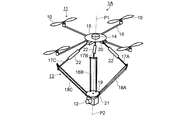
- FIG. 1 is a perspective view schematically showing a drone flying object 1A according to a first example of the first embodiment.
- a drone flying object 1A includes a flying object body 11 having a vertical propeller 10, a robot arm 13 to which a camera 12 as an example of a work device is attached, and a sensor disposed on a base 15 of the flying object body 11. Acceleration sensor 14.
- the flying body 11 includes four propellers 10 disposed at the tips of four frames 16 extending radially from the base 15.
- Such a flying body 11 is generally called a drone or a multicopter, and the number of propellers 10 is not limited to four as shown, but may be one, three, five, or six. .
- the shape is not limited to vertical, and other shapes such as a shape extending obliquely upward may be adopted or mixed.
- a drone flying vehicle equipped with a robot arm is referred to as a robot arm drone. Since the robot arm 13 is disposed on the lower side of the flying body 11, it may be called a suspended robot arm.
- the base 15 connects the four propellers 10 and is not shown in the figure, a control unit that controls driving control of the propeller 10 and the robot arm 13 and photographing control by the camera 12, and between the control unit and the operator It is equipped with a communication interface that enables information communication and a battery or storage battery as an energy source.
- the configuration of the flying body 11 is well known and will not be described in detail.
- the working equipment is not limited to the camera 12 (including a video camera), and is equipped with an acoustic inspection device such as a hammering inspection device, a sprayer for removing harmful small animals such as wasps, a removal tool, or a cleaning tool. It is possible.
- the parallel link mechanism 13 includes single arm portions 17A, 17B, and 17C extending radially from the base portion 15, and parallel arm portions 18A, 18B, and 18C coupled to the single arm portions 17A, 17B, and 17C.
- the tips of the portions 18A, 18B, and 18C are connected to a base portion 19 to which the camera 12 is attached.
- the single arm portions 17A, 17B, and 17C are connected to the base portion 15 by a universal joint 20 or the like, and the parallel arm portions 18A, 18B, and 18C are connected to the base portion 19 by a universal joint 21 or the like.
- the single arm portions 17A, 17B, and 17C and the parallel arm portions 18A, 18B, and 18C are configured in three pairs, but are not limited to three pairs, and may be four pairs or five pairs.
- a linear actuator 22 is arranged in the middle of the length direction of each of the single arm portions 17A, 17B, and 17C. Although illustration is omitted, the linear actuator 22 is preferably a ball screw mechanism including a servo motor and a ball screw excellent in responsiveness and accuracy. The linear actuator 22 can extend and contract each of the single arm portions 17A, 17B, and 17C independently.
- a drone flying object 1A shown in FIG. 1 represents a posture during stable flight (for example, horizontal flight), and the center axis P1 of the flying object body 11 coincides with the center axis P2 of the camera 12 (the platform 19). Represents the case. That is, the posture is when the linear actuator 22 is controlled so that the lengths of the single arm portions 17A, 17B, and 17C are the same. The position of the camera 12 at this time is set as a reference position.
- the drone flying object 1A may be shaken or moved due to disturbances such as gusts, turbulence of airflow, turbulence of flying levitation, or blowback when approaching a structure.
- disturbances such as gusts, turbulence of airflow, turbulence of flying levitation, or blowback when approaching a structure.
- the object to be photographed disappears from the field of view of the camera 12, deviates from a desired angle, or the focal length shifts.
- it is required to maintain the camera 12 in the posture and position before the disturbance is applied even when the disturbance is applied. This will be described with reference to FIG.
- FIG. 2 is a perspective view schematically showing the drone flying object 1A when the drone flying object 1A shown in FIG. 1 receives a disturbance and moves in the horizontal direction and the vertical direction due to the disturbance.
- the drone flying object 1A shown in FIG. 2 moves up from the stable flight posture (see FIG. 1) to the right in the figure (side-sliding) due to a disturbance, the movement is detected by the acceleration sensor 14, and the detected value is obtained. Based on this, the linear actuator 22 is driven, and the posture and position of the camera 12 are maintained at the reference position before the disturbance.
- the acceleration sensor 14 is a three-axis acceleration sensor, and detects X-axis, Y-axis orthogonal to the X-axis, and Z-axis acceleration orthogonal to the X-axis and Y-axis.
- the acceleration sensor 14 detects the acceleration received by the drone aircraft 1A due to disturbance. From the detection value of the acceleration sensor 14, the moving speed of the camera 12, the moving amount from the reference position, and the moving direction are calculated, and the position and orientation of the camera 12 are corrected to the reference position in the opposite phase to the disturbance direction. Position correction can be performed by driving the linear actuator 22 and adjusting the lengths of the single arm portions 17A, 17B, and 17C. As a result, even if the flying body 11 moves due to disturbance, the position and posture of the camera 12 can be maintained unchanged from those before receiving the disturbance.
- the correctable range is a movable range of the parallel link mechanism 13.
- the camera 12 is rotatably mounted on the base 19.
- the camera 12 can be rotated at an arbitrary angle in the horizontal direction.
- the camera angle is rotated by rotating the camera 12 in the reverse direction.
- a motor (servo motor) or a rotary actuator (not shown) is disposed between the camera 12 and the base 19.
- the base 15 may be provided with an angular velocity sensor (not shown) in addition to the acceleration sensor 14.
- the camera 12 is a gimbal camera or a pan head camera that can be biased in the pan and tilt directions, a clear image can be taken even if the camera 12 shakes due to disturbance.
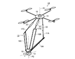
- FIG. 3 is a perspective view schematically showing a drone flying vehicle 1B according to a second example of the first embodiment.
- the drone aircraft 1A of the first embodiment described above being a suspended robot arm in which the parallel link mechanism 13 is disposed on the lower side of the aircraft body 11
- the drone aircraft 1B of the second embodiment is It is a saddle type robot arm in which the parallel link mechanism 13 is arranged above the flying body 11. Therefore, the difference from the first embodiment will be mainly described, and portions that can be described in the same manner as in the first embodiment are denoted by the same reference numerals as those in FIGS.
- a parallel link mechanism 13 as a robot arm is disposed above the base 15 of the flying object body 11.
- the parallel arm portions 18 A, 18 B, and 18 C are connected to the base portion 19 by a universal joint 21, and the single arm portions 17 A, 17 B, and 17 C are connected to the base portion 15 by a universal joint 20.
- a linear actuator 22 is disposed in the middle of the length direction of each of the single arm portions 17A, 17B, and 17C, and each of the single arm portions 17A, 17B, and 17C can be independently extended and contracted. Yes.
- FIG. 3 represents a state during stable flight (for example, horizontal flight), and the center axis P1 of the flying object body 11 coincides with the center axis P2 of the camera 12 (the pedestal part 19). ing.
- This is the position (posture) in which the linear actuator 22 is controlled so that the lengths of the single arm portions 17A, 17B, and 17C are the same, with the position and posture of the camera 12 at this time as the reference position.
- an acceleration sensor 14 is disposed on the side of the base 19 opposite to the camera mounting side.
- the camera 12 is mounted on a substantially L-shaped camera frame 30 provided on the upper surface of the base 19. Between the horizontal plate portion 30A and the base portion 19 of the camera frame 30, an actuator 31 that rotates the camera 12 in the horizontal direction (the rotation direction is indicated by a solid arrow) is disposed, and the camera 12 is mounted on the vertical plate portion 30B. An actuator 32 that is inclined in the vertical direction with respect to the horizontal plate portion 30A (the rotation direction is indicated by a dotted arrow) is disposed. The camera 12 is fixed to the vertical plate portion 30B, and the vertical plate portion 30B is connected to the horizontal plate portion 30A so that it can be bent in the direction of the dotted arrow.
- FIG. 4 is a perspective view schematically showing the drone flying object 1B when the drone flying object 1B shown in FIG. 3 receives a disturbance and moves in the horizontal direction and the vertical direction due to the disturbance.
- the drone flying body 1B shown in FIG. 4 descends while moving (sliding) to the right in the figure due to disturbance from a stable flight posture (see FIG. 3)
- the movement is detected by the acceleration sensor 14, and the detected value is obtained.
- the linear actuator 22 is driven to maintain the posture and position of the camera 12 at the reference position before the disturbance is applied. That is, the position of the central axis P2 of the camera 12 is the same as before the disturbance.
- the acceleration sensor 14 detects the acceleration received by the drone aircraft 1B due to disturbance.
- the moving speed due to the disturbance, the moving amount from the reference position, and the moving direction are calculated, and the position and orientation of the camera 12 are corrected to the reference position in the opposite phase to the movement of the flying body 11.
- the linear actuator 22 By driving the linear actuator 22 and adjusting the length of each of the single arm portions 17A, 17B, and 17C, the position in the horizontal direction (horizontal direction in the figure) and the vertical direction (vertical direction in the figure) with respect to the flying body 11 is changed. Can do. Therefore, even if the drone flying object 1B shakes or moves due to a disturbance, the position and posture of the camera 12 do not change with respect to the reference position before the disturbance.
- the camera 12 can be rotated in the horizontal direction by an actuator 31, and the elevation angle can be adjusted by an actuator 32.
- the camera angle can be maintained by rotating the camera 12 in the reverse direction.
- the base 15 may be provided with an angular velocity sensor (not shown) in addition to the acceleration sensor 14.
- the camera 12 is a gimbal camera or a pan head camera that can be biased in the pan and tilt directions, a clear image can be taken even if the camera 12 is shaken due to disturbance during shooting.
- the working device such as a sounding inspection machine or another inspection machine is mounted in place of the camera 12. It is possible to maintain the work position and work state before the disturbance with respect to the shaking and movement of the flying body 11 due to the disturbance.
- the drone flying objects 1A and 1B of the first embodiment described above include a flying object body 11 having a propeller 10, a parallel link mechanism 13 that is a robot arm provided with a work device such as a camera 12 or an inspection machine, and a disturbance. And an acceleration sensor 14 that is a sensor that detects the shaking and movement of the flying body 11 due to disturbance to the position and posture of the work equipment before the operation is applied, and the parallel link mechanism 13 is based on the detection value of the acceleration sensor 14.
- the camera 12 is moved in the opposite phase according to the movement and shaking of the flying body 11 when a disturbance is applied, and the camera 12 is maintained at the position and posture before the disturbance is applied.
- the acceleration sensor 14 detects shaking and movement of the drone aircraft 1A and 1B caused by disturbance received during the flight, and based on the detected value, the moving speed and the work equipment before the disturbance is applied.
- the movement amount and the movement direction of the vehicle are calculated, and the camera 12 is moved in the opposite phase with respect to the flying body 11 by the parallel link mechanism 13 based on the detection value of the acceleration sensor 14, and the camera 12 is moved to the position and posture before the disturbance is applied.
- the drone flying objects 1A and 1B capable of enlarging photographing such as minute scratches on the inspection target object. Even in a hammering inspection machine, which is a working device other than the camera 12, precise inspection / inspection work can be performed.
- the drone aircraft 1A and 1B have a parallel link mechanism 13 as a robot arm. Since the parallel link mechanism 13 is connected in parallel by a plurality of links from the base part (base part 15) to the final output part (base part 19), motion errors are averaged at each link, and accurate attitude control is performed. Can be performed. In addition, since it is supported by a plurality of links, it is possible to mount a camera 12 or an inspection machine having high rigidity and high weight.
- the drone aircraft 1A, 1B of the first example and the second example of the first embodiment have a triaxial acceleration sensor 14 as a sensor.
- the triaxial acceleration sensor detects acceleration in three directions of the X axis, the Y axis, and the Z axis.
- the acceleration sensor 14 can detect the movement or shaking of the drone flying objects 1A and 1B (flying body main body) in the plane direction or the vertical direction. Accordingly, it is possible to detect movement and shaking in any direction due to disturbance.
- the camera 12 (or inspection device) is rotatably attached to the parallel link mechanism 13 that is a robot arm.
- the camera 12 can suppress the deviation of the focal length and can capture an image at the optimum angle with respect to the object to be imaged or the object to be inspected. It is possible to maintain the position and the posture so as to go to a predetermined predetermined place for inspection.
- the parallel link mechanism 13 including the camera 12 is arranged on the upper side or the lower side of the flying body main body 11, but parallel to both the upper and lower sides of the flying body main body 11.
- the link mechanism 13 may be disposed, and the camera 12 may be disposed on both. If the two cameras 12 photograph from two directions, the object to be imaged can be observed in three dimensions.
- one parallel link mechanism 13 may be provided with a camera 12 and the other parallel link mechanism 13 may be provided with other work equipment. In this way, it is possible to appropriately perform work while observing (photographing) the work site with the camera 12.
- the drone aircraft 1A, 1B of the first embodiment includes the parallel link mechanism 13 as a robot arm, whereas the drone aircraft 1C, 1D of the second embodiment is articulated as a robot arm. It is characterized by having a robot arm 40. Therefore, the difference from the first embodiment will be mainly described.
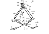
- FIG. 5 is a perspective view showing a drone flying object 1C according to a first example of the second embodiment.
- the drone flying object 1 ⁇ / b> C includes a flying object body 11, an articulated robot arm 40 disposed above the center of the flying object body 11, a camera 12 that is an example of work equipment, and an acceleration. Sensor 14. Since the flying body 11, the camera 12, and the acceleration sensor 14 can have the same configuration as that of the first embodiment, detailed description thereof is omitted.
- the multi-joint robot arm 40 includes two arm parts 41 and 42, a first joint 43 that connects the arm part 41 and the base 15 of the flying body 11, a second joint 44, an arm part 41, and an arm part.
- a third joint 45 that connects the camera 42, and a fourth joint 46 that connects the second arm portion 42 and the camera 12.
- Each joint has an angle sensor and servo motor or angle adjustment actuator (both are not shown).
- the first joint 43 rotates the entire articulated robot arm 40 in the horizontal direction
- the second joint 44 bends the arm portion 41 with respect to the horizontal plane of the flying vehicle body 11, and the third joint 45 extends to the arm portion 41.
- the arm portion 42 is bent
- the fourth joint 46 has a function of bending the camera 12 in the vertical direction with respect to the arm portion 42.
- the camera 12 is further connected to a fourth joint 46 by a fifth joint 47 that can rotate in the circumferential direction of the axis.
- FIG. 5 the rotational action and bending action of each joint are represented by solid arrows.
- An acceleration sensor 14 is disposed below the base 15.
- the acceleration sensor 14 is disposed on an extension line of the rotation axis P ⁇ b> 1 of the first joint 43.
- the articulated robot arm 40 allows the camera 12 to freely rotate in the horizontal direction with respect to the flying vehicle body 11 and move freely in the vertical direction.
- a sixth joint that rotates the camera 12 in the horizontal direction may be provided between the fourth joint 46 and the fifth joint 47 to form a six-axis articulated robot arm.
- the drone aircraft 1C shown in FIG. 5 represents a horizontal stable flight posture, and the position and posture (direction in which the camera 12 faces) of the camera 12 with respect to the vehicle body 11 at this time are set as a reference position.
- the movement is detected by the acceleration sensor 14, and the first joint 43 to the fifth joint 47 are controlled based on the detected value, and the camera It is possible to maintain the reference position and posture before the disturbance is applied to the 12 postures and positions.
- the acceleration sensor 14 detects the acceleration and direction that the drone aircraft 1C (aircraft body 11) receives due to disturbance. Based on the detected acceleration and direction values, the moving speed of the camera 12, the amount of movement from the reference position, and the moving direction are calculated.
- the camera 12 is moved in the opposite phase to the disturbance direction, and the position of the camera 12 and Correct the posture to the reference position. That is, by controlling the driving of the first joint 43 to the fifth joint 47, even if the drone flying object 1C is moved by a disturbance, the position and posture of the camera 12 are not changed from those before the disturbance, and the focal length is changed. The shift is suppressed, and it is possible to take a picture at a predetermined optimum angle.
- FIG. 5 shows an example in which the articulated robot arm 40 is provided with the camera 12 as a work device, but an inspection device such as a hammering inspection device having a hammer and a microphone can be mounted. is there. Further, the articulated robot arm 40 including the camera 12 can be disposed on the lower side of the flying body.
- the drone flying body 1C according to the first example of the second embodiment described above has an articulated robot arm 40 as a robot arm.
- the articulated robot arm 40 can be easily rotated, driven in the horizontal and vertical directions, and has a wider range of motion than the parallel link mechanism 13 described above. Even when moving or tilting, it is possible to maintain the position and posture of the work equipment such as the camera 12 and the inspection machine before the disturbance.
- the camera 12 is attached to the articulated robot arm 40 so as to be rotatable. With such a configuration, it is possible to suppress the deviation of the focal length with respect to the object to be imaged, and it is possible to photograph at a predetermined optimum angle.
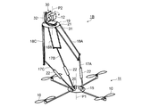
- the drone flying object 1D according to the second embodiment has a vacuum suction device 50 at the tip of the articulated robot arm 40. It is characterized by having. Therefore, the description will be made with the same reference numerals as those in FIG.
- FIG. 6 is a perspective view showing a drone flying object 1D according to a second example of the second embodiment.
- the drone flying object 1 ⁇ / b> D includes a flying object body 11, an articulated robot arm 40 disposed above the center of the flying object body 11, and a vacuum suction device 50 that is an example of work equipment. , And an acceleration sensor 14. Since the structures of the flying body 11 and the articulated robot arm 40 are the same as those of the first embodiment (see FIG. 5), detailed description thereof is omitted.
- a vacuum suction device 50 is attached to the fourth joint 46.
- the vacuum suction device 50 includes a suction pad 51 that is a suction part that sucks a structure, a suction cylinder part 52 that is airtightly connected to the suction pad 51, and a suction fan (not shown) disposed in the suction cylinder part 52. And have.
- An exhaust port 53 is provided in the tail portion of the suction cylinder portion 52 on the fourth joint 46 side.
- a suction hole 54 is provided at the bottom of the suction pad 51, the suction hole 54 communicates with the exhaust port 53, and a suction fan is disposed between the suction hole 54 and the exhaust port 53.
- the drone flying object 1D shown in FIG. 6 represents a stable flight posture, and the position and posture of the vacuum suction device 50 at this time with respect to the flying body main body 11 (the direction in which the vacuum suction device 50 faces the suction target) are used as the reference position. .
- the drone flying object 1D moves (slide) due to disturbance from the stable flight posture, the movement is detected by the acceleration sensor 14, and the first joint 43 to the fourth joint 46 are controlled based on the detected value.
- the position and posture of the suction device 50 before the disturbance is applied can be maintained.
- the moving speed of the vacuum suction device 50, the amount of movement from the reference position, and the moving direction are calculated from the detection value of the acceleration sensor, and the vacuum suction device 50 is moved in a phase opposite to the disturbance direction based on these values.
- the position and posture of the vacuum suction device 50 are corrected before disturbance.
- the position and posture of the vacuum suction device 50 remain close to the structure to be sucked without changing from before the disturbance,
- the suction pad 51 is attracted to the structure.
- the position and posture of the drone flying object 1D can be fixed stationary. If the suction state is maintained, the stationary posture can be maintained even when the propeller 12 is stopped.
- the vacuum suction device 50 is provided as the suction portion.
- the suction portion may be configured only by the suction pad 51 having flexibility.
- the articulated robot arm 40 including the vacuum suction device 50 can be disposed on the lower side of the flying body 11.
- the articulated robot arm 40 has the vacuum suction device 50 including the suction pad 51 as a suction unit and the suction fan as a work device. ing.
- the articulated robot arm 40 is controlled based on the detection value of the acceleration sensor 14 to adsorb it at a predetermined position of the structure,
- the drone flying object 1D can be stationary and stabilized. As described above, if the drone flying object 1D is attracted to the structure and the posture is stably stopped, it is possible to appropriately perform inspections such as precise photographing and sound inspection. This will be described with reference to FIG.
- the third embodiment is characterized in that robot arms are provided on both the upper side and the lower side across the flying body 11.
- a parallel link mechanism 13 see FIGS. 1 to 4
- an articulated robot arm 40 see FIGS. 5 and 6) can be provided.
- FIG. 7 illustrates an example thereof.
- FIG. 7 is a perspective view schematically showing a drone flying object 1E according to the third embodiment.
- the drone flying object 1 ⁇ / b> E is arranged on the upper side of the flying object main body 11, is arranged on the lower side of the flying object main body 11, the articulated robot arm 40 including the vacuum suction device 50, and the camera 12.
- the parallel link mechanism 13 is provided.
- the flying body 11 has the same configuration as that described in the first and second embodiments (see FIGS. 1 to 6), and the vacuum suction device 50 and the articulated robot arm 40 are the same as those described in FIG.
- the structure of the parallel link mechanism 13 has the same structure as described in FIGS. Note that the reference numerals in FIG. 7 are the same as those in FIGS. 1 and 6.
- FIG. 7 shows the time when the drone flying object 1E is in a stable flight posture, and the positions and postures of the vacuum suction device 50 and the camera 12 relative to the flying body 11 at this time (directions in which the vacuum suction device 5 and the camera 12 face) are respectively shown.
- the reference position When moving from a stable flight posture due to disturbance (slip), the movement is detected by the acceleration sensor 14, and if the articulated robot arm 40 is moved in the opposite phase to the direction in which acceleration is applied based on the detected value, vacuum suction is performed. The attitude and position of the device 50 can be maintained at the reference position before the disturbance is applied. Therefore, the suction pad 51 can be attracted to a predetermined position of the structure by bringing the vacuum suction device 50 close to the structure to be attracted and driving the suction fan.
- the camera 12 is attached to the parallel link mechanism 13.
- the acceleration sensor 14 detects the acceleration and direction received by the drone flying object 1E due to the disturbance, and the parallel link mechanism 13 is controlled in the opposite phase to the disturbance direction based on the detected value, the position of the camera 12 is determined. And the posture can be maintained at the reference position before the disturbance. As a result, the position and posture of the camera 12 can be photographed at a predetermined camera angle without changing from that before the disturbance.
- an inspection machine such as a hammering inspection machine in place of the camera 12 as a work device.
- the vacuum adsorbing device 50 and the drone flying object 1E If it is adsorbed to the structure by the vacuum adsorbing device 50 and the drone flying object 1E is stably stationary and fixed, it performs detailed inspection work such as magnified photographing of a fine flaw etc. of the structure to be inspected and sound inspection. It becomes possible.
- the articulated robot arm 40 including the vacuum suction device 50 is disposed above the flying body 11, and the parallel link mechanism 13 including the camera 12 is disposed below.
- the parallel link mechanism 13 including the camera 12 may be disposed above the flying body 11 and the articulated robot arm 40 including the vacuum suction device 50 may be disposed below.
- the articulated robot arm 40 may be arranged on both the upper side and the lower side of the flying body 11, and either one may be provided with the vacuum suction device 50 and the other may be provided with the camera 12.
- the working device is not limited to the camera 12 and may be equipped with an acoustic inspection device such as a hammering inspection device, a sprayer for a harmful small animal such as a wasp, a removal tool, a cleaning tool, or a maintenance tool. is there.
- an acoustic inspection device such as a hammering inspection device, a sprayer for a harmful small animal such as a wasp, a removal tool, a cleaning tool, or a maintenance tool. is there.
- FIG. 8 is a diagram showing a suspended robot arm
- FIG. 9 is a diagram showing lateral position correction of the suspended robot arm
- FIG. 10 is a diagram showing a saddle type robot arm
- FIG. 11 is a lateral direction of the saddle type robot arm.
- FIG. 12 is a diagram showing position correction
- FIG. 12 is a diagram showing an articulated robot arm
- FIG. 13 is a diagram showing a suction pad articulated robot arm.
- the drone flying body (robot arm drone) according to each embodiment from FIG. 8 to FIG. 13 relates to visual inspection of high places such as a tunnel ceiling and the back of a bridge, pest control for nesting in high places. .
- Unmanned drones are attracting attention as being suitable for inspection of high places and dangerous places, but in order to perform more detailed inspection and work, it is required to reduce the shaking of the flying body.
- the conventional drone-equipped camera and measuring instrument are held on the gimbal stage so that they can be observed and measured vertically and horizontally regardless of the attitude of the flying object, but the vertical movement and sliding movement of the flying object cannot be corrected.
- a large drone is effective to obtain higher static stability, but the moving air width becomes large and obstacle avoidance worsens, and the environment that can be used is limited.
- an accelerometer and a robot arm are mounted on a drone flying body, and a camera and a measuring instrument are attached to the drone flying body. Correct dynamically. By mounting this robot arm, it is possible to correct the shaking, slipping, ascent and descent of the flying object within the range of the robot arm's movable space with the autonomous movement of the arm, and to realize stable stationary of the observation camera and measuring instrument . Moreover, even with a relatively small drone, high stationary stability can be obtained for observation and measurement devices.
- a conventional camera holding structure is suspended from a robot arm attached to the drone, and the vertical movement, left-right movement, and rotation of the aircraft are detected by a three-dimensional acceleration sensor, and the arm is dynamically controlled to stop the movement of the camera holding unit. .
- FIG. 8 shows an embodiment of a suspension type robot arm having a camera base and a camera attached to the tip.
- This robot arm is a parallel link system, which enables lightweight and high-speed position correction.
- Fig. 9 corrects the position by moving the arm horizontally against the drone skidding. Since the present invention focuses on the function when the robot arm is attached to the drone, the explanation of the drone is omitted, and the relative size is drawn smaller than the actual size. The description of the parallel link is also omitted.
- the parallel link arm 104 is installed on the upper surface of the aircraft and is mainly used when the observation target is above the drone.
- FIG. 12 shows an embodiment of the present invention equipped with an articulated robot arm, and a gimbal 106 is attached to the tip of the articulated robot arm 108.
- FIG. 6 shows an embodiment of the present invention equipped with a suction device, and a suction pad 109 is attached to the tip of the robot arm.
- the space at the tip of the arm can be stationary, so battery replacement of the electric drone and refueling in the air are possible with the engine drone.
- ⁇ Multi-layered robot arms can be used as an aerial manipulator such as road lighting maintenance and high-voltage wire insulators.
- 1A, 1B, 1C, 1D, 1E ... drone flying vehicle, 10, 101 ... propeller, 11 ... flying vehicle body, 12, 105 ... camera (working equipment), 13 ... parallel link mechanism, 14, 107 ... acceleration sensor (sensor) 40 ... Articulated robot arm (robot arm), 50 ... Vacuum suction device, 102 ... Motor, 103 ... Frame, 104 ... Parael link arm, 106 ... Gimbal, 108 ... Robot arm, 109 ... Suction pad
Landscapes
- Engineering & Computer Science (AREA)
- Aviation & Aerospace Engineering (AREA)
- Mechanical Engineering (AREA)
- Remote Sensing (AREA)
- Manipulator (AREA)
- Stereoscopic And Panoramic Photography (AREA)
- Accessories Of Cameras (AREA)
- Adjustment Of Camera Lenses (AREA)
- Studio Devices (AREA)
Abstract
プロペラ10を備える飛行体本体11と、カメラ12または検査機などの作業機器を備えるパラレルリンク機構13と、外乱が加わる前の作業機器の位置および姿勢に対する外乱による飛行体本体11の揺れや移動を検出する加速度センサー14と、を有し、パラレルリンク機構13は、加速度センサー14の検出値に基づき、外乱が加わる際の飛行体本体11の揺れや移動に応じて作業機器を逆位相に動かし、作業機器を外乱が加わる前の位置および姿勢に維持するドローン飛行体1A。 飛行中に受ける突風、気流の乱れ、飛翔浮揚気流の乱れ、あるいは構造物に接近した際の吹き返しなどの外乱によってドローン飛行体が揺れたり、移動したりしても、微細な傷などの拡大撮影や精密な点検作業などを行うこと可能なドローン飛行体を実現できる。
Description
本発明は、ドローン飛行体に関する。
昨今、老朽化した社会インフラ(インフラストラクチャー)の点検やメンテナンスが急務となってきている。また、スズメバチなどの有害生物の駆除なども問題になっている。近年、マルチコプターやドローンと称される無人小型飛行体が世界的に広がり、これらドローン飛行体は、空中を自在に飛行させることが可能であることから、高架や橋梁、ビルの壁面、トンネルの天井壁面などの高所や危険個所の点検や各種作業などに活用可能性があると注目されている。
特許文献1には、撮像方向を変更するための可動部を有する雲台カメラを、飛行姿勢を制御することが可能なドローン飛行体に搭載することが開示されている。上記雲台カメラとドローン飛行体は、雲台カメラ、ドローン飛行体のそれぞれを制御することで撮影アングルの調整が可能となっている。
特許文献1に記載の雲台カメラは、パンおよびチルト方向に偏倚制御することが可能であり、ドローン飛行体は速度や姿勢を制御することが可能である。これらの制御は、使用者による制御用端末の操作によって行われる。しかしながら、飛行中の撮影において、突風、気流の乱れ、飛翔浮揚気流の乱れ、あるいは構造物に接近した際の吹き返しなどによってドローン飛行体の位置や姿勢が変化してしまうことがある。このような場合、ドローン飛行体の上下動、滑り移動あるいは回転などに、雲台カメラの姿勢制御やドローン飛行体の制御が追い付かず、所望の撮影アングルが得られないという課題がある。ドローン飛行体が静止安定姿勢を維持しなければできないような精緻な拡大撮影や点検作業などを行うことは困難である。
そこで本発明は、上記課題の少なくとも一つを解決するためになされたものであって、飛行中に受ける突風、気流の乱れ、飛翔浮揚気流の乱れ、あるいは構造物に接近した際の吹き返しなどの外乱によってドローン飛行体が揺れたり、移動したりしても、微細な傷などの拡大撮影や精緻な点検作業などを行うことが可能なドローン飛行体を実現しようとするものである。
[1]本発明のドローン飛行体は、プロペラを備える飛行体本体と、カメラまたは検査機などの作業機器を備えるロボットアームと、外乱が加わる前の前記作業機器の位置および姿勢に対する外乱による前記飛行体本体の移動や揺れを検出するセンサーと、を有し、前記ロボットアームは前記センサーの検出値に基づき、外乱が加わる際の前記飛行体本体の移動や揺れに応じて前記作業機器を逆位相で動かし、前記作業機器を外乱が加わる前の位置および姿勢に維持する、ことを特徴とする。
本発明のドローン飛行体によれば、飛行中に受ける外乱に起因するドローン飛行体の揺れや移動をセンサーで検出し、センサーの検出値に基づきロボットアームを逆位相に動かすことによって、飛行体本体に対してカメラや検査機器などの作業機器を外乱が加わる前の位置および姿勢に維持することが可能となり、被点検対象物の微細な傷などの拡大撮影や他の精緻な点検・検査作業などを可能とするドローン飛行体を実現できる。
[2]本発明のドローン飛行体においては、前記ロボットアームとしてパラレルリンク機構を有することが好ましい。
パラレルリンク機構は、ベース部から最終出力部までが複数のリンクで並列に連結されることから、動きの誤差が各リンクで平均化され作業機器の正確な姿勢制御を行うことができる。また、複数のリンクで支持されることから剛性が高く、重量のあるカメラや検査機などの作業機器を搭載することができる。
[3]本発明のドローン飛行体においては、前記ロボットアームとして多関節ロボットアームを有することが好ましい。
多関節ロボットアームは、作業機器の回転、水平方向および垂直方向への駆動を容易に制御することが可能で、パラレルリンク機構よりも可動範囲が広いため、外乱によって飛行体本体が大きく移動したり、傾いたりする場合においても、カメラや検査機などの作業機器を外乱前の位置や姿勢に維持することができる。
[4]本発明のドローン飛行体においては、前記センサーは、3軸加速度センサーであることが好ましい。
3軸加速度センサー(3次元加速度センサー)は、X軸、X軸に直交するY軸、並びに、X軸およびY軸に直交するZ軸の3方向の加速度を検出可能である。この加速度センサー14によって、平面方向あるいは垂直方向のドローン飛行体(飛行体本体)移動や揺れを検出できる。したがって、外乱によるドローン飛行体のあらゆる方向の移動や揺れを検出することが可能となる。
[5]本発明のドローン飛行体においては、前記カメラは、前記ロボットアームに対して回転自在に取り付けられることが好ましい。
このようにすれば、被撮影対象物に対して、飛行体本体の姿勢ずれがあっても、カメラを被撮影対象物に向けられるので焦点距離のずれを抑制し、さらに最適アングルでの撮影が可能となる。
[6]本発明のドローン飛行体においては、前記多関節ロボットアームは、前記作業機器として吸着部と吸引ファンとを備える真空吸着装置を有することが好ましい。
構造物に吸着する際に、外乱によりドローン飛行体に揺れや移動があってもセンサーの検出値に基づきロボットアームを制御することで、吸着部の位置を静止安定させ、所定位置に吸着させることが可能となる。構造物に真空吸着装置によって吸着させれば、飛行体本体の位置および姿勢を安定静止姿勢で維持することが可能となる。
[7]本発明のドローン飛行体においては、前記ロボットアームは、前記飛行体本体を挟んで上方側または/および下方側に配置されることが好ましい。
このようにすれば、ロボットアームは、飛行体本体の上方側または下方側に撮影対象や検査作業対象がある場合、あるいは、構造物に突出物や段差などによって飛行可能範囲が制限されるような場合において、作業可能範囲を拡げることが可能となる。また、ロボットアームを飛行体本体の上下ともに配置すれば、たとえば、上方側にカメラ、下方側に検査機を配置すれば、カメラで点検場所を観察しながら点検作業を行うことが可能となる。
[8]本発明のドローン飛行体においては、前記ロボットアームは、前記飛行体本体を挟んで上方側および下方側の両方に配置され、一方の前記ロボットアームに前記作業機器を備え、他方の前記ロボットアームに前記真空吸着装置が取り付けられることが好ましい。
このような構成にすることによって、構造物に吸着する際に、飛行体本体が外乱により揺れや移動があってもロボットアームを制御することで、吸着部の位置を安定させて吸着し、吸着静止安定姿勢で作業可能となるので、精密な拡大撮影や精緻な点検・検査作業を実施できる。
以下、本発明の実施の形態に係るドローン飛行体について、図1~図13を参照しながら説明する。
[第1の実施の形態]
図1は、第1の実施の形態の第1実施例に係るドローン飛行体1Aを模式的に示す斜視図である。ドローン飛行体1Aは、垂直状のプロペラ10を備える飛行体本体11と、作業機器の1例としてのカメラ12が取り付けられたロボットアーム13と、飛行体本体11の基部15に配置されたセンサーとしての加速度センサー14とを有している。飛行体本体11は、基部15から放射状に延在された4本のフレーム16の先端に配置される4個のプロペラ10を備える。このような飛行体本体11は、一般にドローンまたはマルチコプターと呼ばれ、プロペラ10の数は、図示するような4個に限定されず、1個、3個、5個あるいは6個のものでもよい。また、形状は、垂直に限定されず、斜め上に伸びる形状など他の形状のものを採用したり、混在させてもよい。上記のようにドローン飛行体にロボットアームを装備したものをロボットアームドローンと称する。ロボットアーム13は、飛行体本体11の下方側に配置されているので懸架型ロボットアームと呼ぶことがある。
図1は、第1の実施の形態の第1実施例に係るドローン飛行体1Aを模式的に示す斜視図である。ドローン飛行体1Aは、垂直状のプロペラ10を備える飛行体本体11と、作業機器の1例としてのカメラ12が取り付けられたロボットアーム13と、飛行体本体11の基部15に配置されたセンサーとしての加速度センサー14とを有している。飛行体本体11は、基部15から放射状に延在された4本のフレーム16の先端に配置される4個のプロペラ10を備える。このような飛行体本体11は、一般にドローンまたはマルチコプターと呼ばれ、プロペラ10の数は、図示するような4個に限定されず、1個、3個、5個あるいは6個のものでもよい。また、形状は、垂直に限定されず、斜め上に伸びる形状など他の形状のものを採用したり、混在させてもよい。上記のようにドローン飛行体にロボットアームを装備したものをロボットアームドローンと称する。ロボットアーム13は、飛行体本体11の下方側に配置されているので懸架型ロボットアームと呼ぶことがある。
基部15は、4個のプロペラ10を連結するとともに、図示は省略するが、プロペラ10、ロボットアーム13の駆動制御、カメラ12による撮影制御を司る制御部と、制御部と操作者との間の情報通信を可能にする通信インターフェースや、エネルギー源としての電池または蓄電池などを搭載している。飛行体本体11の構成は周知のものであり詳しい説明は省略する。また、作業機器としてはカメラ12(ビデオカメラを含む)に限らず打音点検装置などの音響的検査機器、スズメバチなどの有害小動物の駆除用薬剤の噴霧器、除去具、あるいは洗浄具などを搭載することが可能である。
図1に示すロボットアーム13は、パラレルリンク機構(またはパラレルリンクメカニズムという)を例示しているので、以降、ロボットアーム13をパラレルリンク機構13と記載する。パラレルリンク機構13は、基部15から放射状に延びるシングルアーム部17A,17B,17Cと、シングルアーム部17A,17B,17Cに連結されるパラレルアーム部18A,18B,18Cと、を有し、パラレルアーム部18A,18B,18Cの先端はカメラ12を取り付ける台部19に連結されている。シングルアーム部17A,17B,17Cは基部15に自在継手20などで連結され、パラレルアーム部18A,18B,18Cは台部19に自在継手21などで連結される。
図1に示す例では、シングルアーム部17A,17B,17Cとパラレルアーム部18A,18B,18Cは3対で構成されているが、3対に限らず4対あるいは5対にしてもよい。シングルアーム部17A,17B,17Cの各々の長さ方向の中間には、リニアアクチュエータ22が配置されている。図示は省略するが、リニアアクチュエータ22には、応答性や精度が優れたサーボモータおよびボールねじを備えたボールねじ機構が好ましい。リニアアクチュエータ22は、シングルアーム部17A,17B,17Cの各々を独立して伸ばしたり、縮めたりすることが可能となっている。シングルアーム部17A,17B,17Cの伸縮によって、パラレルアーム部18A,18B,18Cの各々の台部19に対する角度を変えることが可能で、そのことによって飛行体本体11に対する水平方向(図示横方向)および垂直方向(図示縦方向)の位置や姿勢を変えることができる。
図1に示すドローン飛行体1Aは、安定飛行時(たとえば、水平飛行)の姿勢を表しており、飛行体本体11の中心軸P1と、カメラ12(台部19)の中心軸P2が一致する場合を表している。すなわち、シングルアーム部17A,17B,17Cの各長さが同じになるようにリニアアクチェータ22を制御したときの姿勢である。この時のカメラ12の位置を基準位置とする。
ドローン飛行体1Aは、飛行中に受ける突風、気流の乱れ、飛翔浮揚気流の乱れ、あるいは構造物に接近した際の吹き返しなどの外乱によって、揺れたり、移動したりすることがあり、そのことによって、カメラ12の視野から撮影すべき対象物が消えてしまったり、所望のアングルから外れてしまったり、焦点距離がずれてしまうことがある。その解決策として、外乱が加えられてもカメラ12を外乱が加わる前の姿勢や位置に維持することが求められる。そのことについて、図2を参照して説明する。
図2は、図1に示すドローン飛行体1Aが外乱を受け、外乱によって水平方向および垂直方向に移動する際のドローン飛行体1Aを模式的に示す斜視図である。図2に示すドローン飛行体1Aは、安定飛行姿勢(図1参照)から外乱によって図示右方へ移動(横滑り)しながら上昇した際に、その移動を加速度センサー14で検出し、その検出値に基づきリニアアクチュエータ22を駆動し、カメラ12の姿勢および位置を外乱前の基準位置に維持していることを表している。加速度センサー14は、3軸加速度センサーであって、X軸、X軸に直交するY軸、並びにX軸およびY軸に直交するZ軸の加速度を検出する。加速度センサー14は、外乱によってドローン飛行体1Aが受ける加速度を検出する。加速度センサー14の検出値から、カメラ12の移動速度、基準位置からの移動量および移動方向を算出して、外乱方向に対して逆位相でカメラ12の位置および姿勢を基準位置に補正する。位置補正は、リニアアクチュエータ22を駆動し、シングルアーム部17A,17B,17Cの長さを調整することによって行うことが可能である。このことによって、飛行体本体11が外乱によって移動してもカメラ12の位置や姿勢は、外乱を受ける前に対して変わらずに維持できている。補正可能範囲は、パラレルリンク機構13の可動範囲である。
カメラ12は、台部19に回転可能に装着される。図2に示す例においては、カメラ12は水平方向に任意の角度に回転可能であって、外乱によってドローン飛行体1Aが回転する際には、カメラ12を逆方向に回転することで、カメラアングルを一定に維持することが可能となる。カメラ12と台部19の間には、不図示のモータ(サーボモータ)または回転アクチュエータが配設される。ドローン飛行体1Aの回転を検出するには、基部15に加速度センサー14に加えて角速度センサー(不図示)を備えるようにすればよい。また、カメラ12は、パンおよびチルト方向に偏倚可能なジンバルカメラまたは雲台カメラなどとすれば、外乱によってカメラ12が揺れても鮮明な画像撮影を行うことが可能となる。
図3は、第1の実施の形態の第2実施例に係るドローン飛行体1Bを模式的に示す斜視図である。前述した第1実施例のドローン飛行体1Aが、飛行体本体11の下方側にパラレルリンク機構13を配置した懸架型ロボットアームであることに対して、第2実施例のドローン飛行体1Bは、飛行体本体11の上方側にパラレルリンク機構13を配置する櫓型ロボットアームであることに特徴を有する。よって、第1実施例との相違個所を中心に説明し、第1実施例と同じように説明できる部分には、図1および図2と同じ符号を付している。
ドローン飛行体1Bは、飛行体本体11の基部15の上方側にロボットアームとしてのパラレルリンク機構13が配置されている。パラレルリンク機構13は、パラレルアーム部18A,18B,18Cが台部19に自在継手21によって連結され、シングルアーム部17A,17B,17Cが基部15に自在継手20によって連結される。シングルアーム部17A,17B,17C各々の長さ方向の中間にはリニアアクチュエータ22が配置され、シングルアーム部17A,17B,17Cの各々を独立して伸ばしたり、縮めたりすることが可能となっている。図3に示すドローン飛行体1Bは、安定飛行時(たとえば、水平飛行)の状態を表しており、飛行体本体11の中心軸P1と、カメラ12(台部19)の中心軸P2が一致している。この時のカメラ12の位置および姿勢を基準位置とし、シングルアーム部17A,17B,17Cの各長さが同じになるようにリニアアクチェータ22を制御した位置(姿勢)である。なお、図示は省略するが、台部19のカメラ搭載側の反対側には、加速度センサー14が配置されている。
カメラ12は、基部19の上面に設けられた略L字形状のカメラフレーム30に装着されている。カメラフレーム30の水平板部30Aと基部19の間には、カメラ12を水平方向に回転する(回転方向を実線の矢印で表す)アクチュエータ31が配置され、垂直板部30Bには、カメラ12を水平板部30Aに対して垂直方向に傾ける(回転方向を点線の矢印で表す)アクチュエータ32が配置される。カメラ12は、垂直板部30Bに固定され、垂直板部30Bは水平板部30Aに対して点線の矢印方向に折り曲げ可能に連結されている。
図4は、図3に示すドローン飛行体1Bが外乱を受け、外乱によって水平方向および垂直方向に移動する際のドローン飛行体1Bを模式的に示す斜視図である。図4に示すドローン飛行体1Bは、安定飛行姿勢(図3参照)から外乱によって図示右方へ移動(横滑り)しながら降下した際に、その移動を加速度センサー14で検出し、その検出値に基づきリニアアクチュエータ22を駆動し、カメラ12の姿勢および位置を外乱が加わる前の基準位置に維持していることを表している。すなわち、カメラ12の中心軸P2の位置は、外乱前と変わらない。加速度センサー14は、外乱によってドローン飛行体1Bが受ける加速度を検出する。この検出値から、外乱による移動速度、基準位置からの移動量および移動方向を算出して、飛行体本体11の移動に対して逆位相でカメラ12の位置および姿勢を基準位置に補正する。リニアアクチュエータ22を駆動し、シングルアーム部17A,17B,17C各々の長さを調整することによって、飛行体本体11に対する水平方向(図示横方向)および垂直方向(図示縦方向)の位置を変えることができる。したがって、ドローン飛行体1Bが外乱によって揺れたり、移動したりしても、カメラ12の位置や姿勢は外乱を受ける前の基準位置に対して変わらない。
カメラ12は、アクチュエータ31によって水平方向に回転可能で、さらにアクチュエータ32によって仰角が調整可能となっている。外乱によってドローン飛行体1Bが移動、回転、または傾く際には、カメラ12を逆方向に回転させることで、カメラアングルを維持することが可能となる。ドローン飛行体1Bの回転を検出するには、基部15に加速度センサー14に加えて角速度センサー(不図示)を備えるようにすればよい。また、カメラ12は、パンおよびチルト方向に偏倚可能なジンバルカメラまたは雲台カメラなどにすれば、撮影中に外乱によってカメラ12が揺れても鮮明な画像撮影を行うことが可能となる。なお、上記第1実施例および第2実施例では、作業機器としてカメラ12を搭載する例をあげて説明したが、カメラ12に替えて打音検査機や他の検査機などの作業機器を搭載することが可能で、外乱による飛行体本体11の揺れや移動などに対して外乱前の作業位置および作業状態を維持できる。
以上説明した第1の実施の形態のドローン飛行体1A,1Bは、プロペラ10を有する飛行体本体11と、カメラ12または検査機などの作業機器を備えるロボットアームであるパラレルリンク機構13と、外乱が加わる前の作業機器の位置および姿勢に対する外乱による飛行体本体11の揺れや移動を検出するセンサーである加速度センサー14と、を有し、パラレルリンク機構13は加速度センサー14の検出値に基づき、外乱が加わる際の飛行体本体11の移動や揺れに応じてカメラ12を逆位相で動かし、カメラ12を外乱が加わる前の位置および姿勢に維持する。
このように構成すれば、飛行中に受ける外乱に起因するドローン飛行体1A,1Bの揺れや移動を加速度センサー14で検出し、その検出値に基づき移動速度や、外乱が加わる前の作業機器からの移動量や移動方向を算出し、加速度センサー14の検出値に基づきパラレルリンク機構13によって飛行体本体11に対してカメラ12を逆位相で動かし、カメラ12を外乱が加わる前の位置および姿勢に維持することが可能となる。そのことによって、被点検対象物の微細な傷などの拡大撮影が可能なドローン飛行体1A,1Bを実現できる。カメラ12以外の作業機器である打音検査機などにおいても、精緻な点検・検査作業が可能となる。
また、ドローン飛行体1A,1Bにおいては、ロボットアームとしてパラレルリンク機構13を有している。パラレルリンク機構13は、ベース部(基部15)から最終出力部(台部19)までが複数のリンクで並列に連結されることから、動きの誤差が各リンクで平均化され、正確な姿勢制御を行うことが可能となる。また、複数のリンクで支持されることから剛性が高く、重量の大きいカメラ12や検査機などを搭載することができる。
また、第1の実施の形態の第1実施例および第2実施例のドローン飛行体1A,1Bにおいては、センサーとしては3軸加速度センサー14を有している。3軸加速度センサーは、X軸、Y軸およびZ軸の3方向の加速度を検出する。この加速度センサー14によって、平面方向あるいは垂直方向のドローン飛行体1A,1B(飛行体本体)の移動や揺れを検出できる。したがって、外乱によるドローン飛行体あらゆる方向の移動や揺れを検出することが可能となる。
また、ドローン飛行体1A,1Bにおいては、カメラ12(または検査機器)は、ロボットアームであるパラレルリンク機構13に対して回転自在に取り付けられている。このような構成にすれば、被撮影対象物または被点検対象物に対して、カメラ12においては、焦点距離のずれを抑制し、かつ、最適アングルで撮影可能に、検査機(不図示)においては、点検の最適な所定場所に向かうように位置および姿勢を維持することが可能となる。
以上説明した第1の実施の形態においては、飛行体本体11の上方側または下方側にカメラ12を備えるパラレルリンク機構13を配置しているが、飛行体本体11の上方および下方の両方にパラレルリンク機構13を配置し、両方にカメラ12を配置してもよい。2台のカメラ12で2方向から撮影すれば、被撮像物を立体的に観察可能となる。また、一方のパラレルリンク機構13にカメラ12を備え、他方のパラレルリンク機構13に他の作業機器を備えるようにしてもよい。このようにすれば、作業個所をカメラ12で観察(撮影)しながら作業を適切に行うことが可能となる。
[第2の実施の形態]
続いて、第2の実施の形態に係るドローン飛行体1C、1Dについて図5、図6を参照して説明する。第1の実施の形態のドローン飛行体1A,1Bがロボットアームとしてパラレルリンク機構13を備えていることに対して、第2の実施の形態のドローン飛行体1C,1Dは、ロボットアームとして多関節ロボットアーム40を有することに特徴を有する。そこで、第1の実施の形態との相違個所を中心に説明する。
続いて、第2の実施の形態に係るドローン飛行体1C、1Dについて図5、図6を参照して説明する。第1の実施の形態のドローン飛行体1A,1Bがロボットアームとしてパラレルリンク機構13を備えていることに対して、第2の実施の形態のドローン飛行体1C,1Dは、ロボットアームとして多関節ロボットアーム40を有することに特徴を有する。そこで、第1の実施の形態との相違個所を中心に説明する。
図5は、第2の実施の形態の第1実施例に係るドローン飛行体1Cを示す斜視図である。図5に示すように、ドローン飛行体1Cは、飛行体本体11と、飛行体本体11の中央部上方に配置される多関節ロボットアーム40と、作業機器の1例であるカメラ12と、加速度センサー14とを有している。飛行体本体11、カメラ12および加速度センサー14は、第1の実施の形態と同じ構成のものを使用することが可能なので詳しい説明は省略する。多関節ロボットアーム40は、2本のアーム部41,42と、アーム部41と飛行体本体11の基部15とを連結する第1関節43と、第2関節44と、アーム部41とアーム部42とを連結する第3関節45と、第2アーム部42とカメラ12を連結する第4関節46とを有している。
各関節の各々は、角度センサーとサーボモータまたは角度調整アクチュエータを有している(共に図示は省略)。第1関節43は多関節ロボットアーム40の全体を水平方向に回転し、第2関節44は、飛行体本体11の水平面に対してアーム部41を屈曲し、第3関節45はアーム部41に対してアーム部42を屈曲し、第4関節46はアーム部42に対してカメラ12を上下方向に屈曲させる機能を備えている。カメラ12は、さらに第4関節46に対して軸の周方向に回転可能な第5関節47で連結されている。図5には、各関節の回転作用および屈曲作用を実線の矢印で表している。基部15の下方には加速度センサー14が配置される。加速度センサー14は、第1関節43の回転軸P1の延長線上に配置される。カメラ12は、多関節ロボットアーム40によって、飛行体本体11に対して水平方向に自在に回転することや上下方向に自在に移動することが可能になっている。なお、図示は省略するが、第4関節46と第5関節47の間に、カメラ12を水平方向に回転する第6関節を設け、6軸多関節ロボットアームとしてもよい。
図5に示すドローン飛行体1Cは、水平安定飛行姿勢を表し、この時のカメラ12の飛行体本体11に対する位置および姿勢(カメラ12が向く方向)を基準位置とする。安定飛行姿勢から外乱によって、ドローン飛行体11が移動(横滑り)する際に、その移動を加速度センサー14で検出し、その検出値に基づき第1関節43~第5関節47を制御して、カメラ12の姿勢および位置を外乱が加えられる前の基準位置および姿勢を維持することが可能となっている。加速度センサー14は、外乱によってドローン飛行体1C(飛行体本体11)が受ける加速度と方向を検出する。加速度と方向の検出値から、カメラ12の移動速度、基準位置からの移動量および移動方向を算出して、この値に基づきカメラ12を外乱方向に対して逆位相で動かし、カメラ12の位置および姿勢を基準位置に補正する。すなわち、第1関節43~第5関節47を駆動制御することによって、ドローン飛行体1Cが外乱によって移動されてもカメラ12の位置や姿勢は、外乱を受ける前に対して変わらず、焦点距離のずれが抑制され、さらに所定の最適アングルで撮影が可能となる。
なお、図5に示す例は、多関節ロボットアーム40に作業機器としてカメラ12を備える例を示しているが、ハンマーとマイクとを備える打音点検装置などの検査機器を搭載することが可能である。また、カメラ12を備える多関節ロボットアーム40を飛行体本体の下方側に配置することが可能である。
以上説明した第2の実施の形態の第1実施例に係るドローン飛行体1Cは、ロボットアームとして多関節ロボットアーム40を有している。多関節ロボットアーム40は、回転、水平方向および垂直方向への駆動および制御を容易に行うことが可能で、前述したパラレルリンク機構13よりも可動範囲が広いため、外乱によってドローン飛行体1Cが大きく移動したり、傾いたりする場合においても、カメラ12や検査機などの作業機器を外乱前の位置や姿勢を維持することが可能となる。
カメラ12は、多関節ロボットアーム40に対して回転自在に取り付けられる。このような構成にすれば、被撮影対象物に対して、焦点距離のずれを抑制でき、かつ、所定の最適アングルで撮影可能となる。
次に、第2の実施の形態の第2実施例に係るドローン飛行体1Dについて図6を参照して説明する。前述した第1実施例(図5参照)が作業機器としてカメラ12を備えていることに対して、第2実施例に係るドローン飛行体1Dは、多関節ロボットアーム40の先端に真空吸着装置50を備えていることを特徴としている。よって、相違個所を中心に、第1実施例に対して共通部分には図5と同じ符号を付して説明する。
図6は、第2の実施の形態の第2実施例に係るドローン飛行体1Dを示す斜視図である。図6に示すように、ドローン飛行体1Dは、飛行体本体11と、飛行体本体11の中央部上方に配置される多関節ロボットアーム40と、作業機器の1例である真空吸着装置50と、加速度センサー14とを備えている。飛行体本体11および多関節ロボットアーム40の構成は、前述した第1実施例(図5参照)と同じ構成なので詳しい説明を省略する。第4関節46には、真空吸着装置50が取り付けられている。真空吸着装置50は、構造物に吸着する吸着部である吸着パッド51と、吸着パッド51に気密に接続される吸引筒部52と、吸引筒部52内に配置される吸引ファン(不図示)とを有している。吸引筒部52の第4関節46側の尾部には、排気口53が設けられている。吸着パッド51の底部には吸引孔54が設けられ、吸引孔54は排気口53に連通し、吸引孔54と排気口53の間に吸引ファンが配置される。
図6に示すドローン飛行体1Dは、安定飛行姿勢を表し、この時の真空吸着装置50の飛行体本体11に対する位置および姿勢(真空吸着装置50が被吸対象に向く方向)を基準位置とする。安定飛行姿勢から外乱によって、ドローン飛行体1Dが移動(横滑り)する際に、その移動を加速度センサー14で検出し、その検出値に基づき第1関節43~第4関節46を制御すれば、真空吸着装置50の姿勢および位置を外乱が加えられる前の位置および姿勢が維持することができる。すなわち、加速度センサーの検出値から、真空吸着装置50の移動速度、基準位置からの移動量および移動方向を算出して、この値に基づき外乱方向に対して逆位相で真空吸着装置50を動かし、真空吸着装置50の位置および姿勢を外乱前に補正する。
ドローン飛行体1Dが外乱によって移動したり姿勢が変化したりしても真空吸着装置50の位置や姿勢は、外乱を受ける前に対して変わらずに被吸着対象である構造物に近接させて、吸引ファンを駆動すれば吸着パッド51が構造物に吸着する。吸着が確認できたところで、多関節ロボットアーム40の駆動を停止すれば、ドローン飛行体1Dの位置および姿勢を静止固定できる。また、吸着状態を保持すれば、プロペラ12を停止しても静止姿勢を保持できる。
なお、図6においては、吸着部として真空吸着装置50を備えているが、被吸着構造物が平滑面であれば、吸着部を柔軟性を有する吸着パッド51のみで構成するようにしてもよい。また、真空吸着装置50を備える多関節ロボットアーム40を飛行体本体11の下方側に配置することが可能である。
以上説明した第2の実施の形態の第2実施例によれば、多関節ロボットアーム40は、作業機器として、吸着部である吸着パッド51と、吸引ファンとを備える真空吸着装置50を有している。構造物に吸着する際に、ドローン飛行体1Dが外乱により揺れや移動があっても加速度センサー14の検出値に基づき多関節ロボットアーム40を制御することで、構造物の所定位置に吸着させ、ドローン飛行体1D静止安定させることが可能となる。このように、構造物にドローン飛行体1Dを吸着させて姿勢を安定静止させれば、精密な撮影および打音検査などの点検を適切に行うことが可能となる。このことについて、図7を参照して説明する。
[第3の実施の形態]
第3の実施の形態は、飛行体本体11を挟んで上方側および下方側の両方にロボットアームを備えることを特徴とする。ロボットアームとしては、パラレルリンク機構13(図1~図4参照)または多関節ロボットアーム40(図5、図6参照)を備えることが可能である。図7にその1例を例示して説明する。
第3の実施の形態は、飛行体本体11を挟んで上方側および下方側の両方にロボットアームを備えることを特徴とする。ロボットアームとしては、パラレルリンク機構13(図1~図4参照)または多関節ロボットアーム40(図5、図6参照)を備えることが可能である。図7にその1例を例示して説明する。
図7は、第3の実施の形態に係るドローン飛行体1Eを模式的に示す斜視図である。図7に示すように、ドローン飛行体1Eは、飛行体本体11の上方側に配置され、真空吸着装置50を備える多関節ロボットアーム40と、飛行体本体11の下方側に配置され、カメラ12を備えるパラレルリンク機構13を有している。飛行体本体11は、前述した第1、第2の実施の形態に記載(図1~図6参照)と同じ構成のもの、真空吸着装置50および多関節ロボットアーム40は図6に記載と同じ構成のもの、パラレルリンク機構13は図1、図2に記載と同じ構成のものを備えている。なお、図7に記載の符号は、図1および図6と同じ符号を付している。
図7は、ドローン飛行体1Eが安定飛行姿勢のときを表し、この時の真空吸着装置50およびカメラ12の飛行体本体11に対する位置および姿勢(真空吸着装置5およびカメラ12が向く方向)をそれぞれの基準位置とする。安定飛行姿勢から外乱によって移動(横滑り)する際に、その移動を加速度センサー14で検出し、その検出値に基づき多関節ロボットアーム40を加速度が加わる方向に対して逆位相に動かせば、真空吸着装置50の姿勢および位置を外乱が加えられる前の基準位置に維持することができる。したがって、被吸着対象である構造物に真空吸着装置50を近接させて、吸引ファンを駆動すれば吸着パッド51が構造物の所定位置に吸着させることができる。
カメラ12は、パラレルリンク機構13に装着されている。前述したように、外乱によってドローン飛行体1Eが受ける加速度と方向を加速度センサー14で検出し、その検出値に基づきパラレルリンク機構13を外乱方向に対して逆位相で制御すれば、カメラ12の位置および姿勢を外乱前の基準位置に維持することができる。このことによって、カメラ12の位置や姿勢は、外乱を受ける前に対して変わらずに、所定のカメラアングルで撮影することが可能となる。なお、作業機器としてカメラ12に替えて打音検査機などの検査機を備えることが可能である。
真空吸着装置50によって構造物に吸着し、ドローン飛行体1Eを安定静止したうえで固定すれば、被点検構造物の微細な傷などの拡大撮影や打音点検などの精緻な点検作業などを行うことが可能となる。
第3の実施の形態(図7参照)においては、飛行体本体11の上方に真空吸着装置50を備える多関節ロボットアーム40を配置し、下方にカメラ12を備えるパラレルリンク機構13を配置しているが、飛行体本体11の上方にカメラ12を備えるパラレルリンク機構13を配置し、下方に真空吸着装置50を備える多関節ロボットアーム40を配置してもよい。また、飛行体本体11の上方および下方側の両方に多関節ロボットアーム40を配置し、どちらか一方が真空吸着装置50を備え、他方がカメラ12を備えるように構成してもよい。なお、作業機器としてはカメラ12に限らず打音点検装置などの音響的検査機器、スズメバチなどの有害小動物の駆除用薬剤の噴霧器、除去具や洗浄具あるいはメンテナンス用具などを搭載することが可能である。
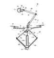
図8は、懸架型ロボットアームを示す図、図9は、懸架型ロボットアーム横方向位置補正を示す図、図10は、櫓型ロボットアームを示す図、図11は、櫓型ロボットアーム横方向位置補正を示す図、図12は、多関節ロボットアームを示す図、図13は、吸着パッド多関節ロボットアームを示す図である。この図8~図13までの各実施の形態に係るドローン飛行体(ロボットアームドローン)は、トンネル天井、橋梁の裏面など高所の撮影目視検査、高所に営巣する害虫駆除などに関するものである。
老朽化する社会インフラの点検が急務となっている。また、スズメバチに代表される有害生物の駆除も、必要とされている。無人のドローン飛行体は高所、危険個所点検に適していると注目されているが、より詳細な点検、作業をするために飛行体の揺れを軽減することが求められている。
ドローン飛行体が接近する際に自然風が対象構造物にあたって発生する乱流、また、ドローン自身の発生する飛翔浮揚気流が構造物に当たって生ずる吹き返しなどの流れの外乱が、接近時にカメラ、計測器の安定支持を困難にしている。
従来ドローン搭載のカメラ、計測器はジンバルステージで保持し、飛行体の姿勢によらず上下左右の観察、計測ができるようにしているが、飛行体の上下搖動、滑り移動は、補正できない。より高い静止安定性を得るために、大型のドローンは有効だが、移動空路幅が大きくなり障害物回避が悪くなり、利用できる環境が限られる。
以下の図8~図13に示す実施の形態では、加速度センサーとロボットアームをドローン飛行体に搭載し、これにカメラ、計測器を取付け、静止飛行時の風などによる揺れ、ブレをロボットアームでダイナミックに補正する。このロボットアームを搭載することにより、ロボットアームの可動空間の範囲内の飛行体の揺れ、滑り、上昇、降下をアームの自律的な動きで補正し、観察カメラ、計測器の安定静止が実現できる。また、比較的に小型のドローンでも従来より、観察、計測機器には高い静止安定性が得られる。
従来ドローンカメラには飛行方向、気体のバンク角度とは独立しに撮影方向を設定できるよう、直行する2軸回転ステージで構成するジンバルステージが用いられている。この機構はパンニング(カメラを左右に動かして撮る技法)にも利用されるために低速であるが、これを高速にして、手振れ補正のように角度姿勢変化を相殺する方法もとれる。しかし、乱流による不安定は角度だけでなく、突き上げ、落下、横滑りなど位置変化を伴う。被写体までの距離が遠く、撮影角度補正だけで、これらの空間移動を無視できる場合はこれで足りるが、被写体にある微細な傷を観察する望遠などの拡大映像を撮るには空間補正が必須となる。
ドローンに取付けたロボットアームに従来のカメラ保持構造を懸架して、機体の上下動、左右動、回転を3次元加速度センサーで検知し、アームをダイナミックに制御して、カメラ保持部の動きを止める。
図8、図9は、本発明の実施例であって、101~107は図10、図11も同様。図8は先端にカメラ台とカメラを取り付けた懸架型のロボットアームの実施例を示す。このロボットアームはパラレルリンク方式で、軽量かつ高速の位置補正が可能。
図9はドローンの横滑りに対してアームを水平方向に動かし、位置の補正を行う。本発明は、ドローンにロボットアームを取り付けた際の機能に主眼があるので、ドローンの説明は省略し、また、相対的な大きさも実際より小さく描いてある。パラレルリンクも説明を省略する。
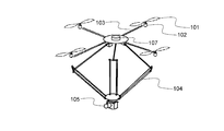
図10、図11は櫓型ロボットアームを装着した本発明の実施例を示す。パラレルリンクアーム104を機体上面に装備し、主に観察対象がドローンの上方にある場合に使用する。
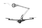
図12は多関節ロボットアームを装備した本発明の実施例を示し、多関節ロボットアーム108の先端にジンバル106を取り付けてある。
図6は吸着器を装着した本発明の実施例で、ロボットアーム先端に吸着パッド109を装着している。
アーム先端の空間静止が可能となるので、電動ドローンの電池交換、エンジンドローンでは空中燃料補給が可能となる。
ロボットアームを多層にすることで、道路照明灯のメンテ、高圧線絶縁碍子など空中マニュピレータとしての用途が開ける。
1A,1B,1C,1D,1E…ドローン飛行体、10、101…プロペラ、11…飛行体本体、12,105…カメラ(作業機器)、13…パラレルリンク機構、14,107…加速度センサー(センサー)、40…多関節ロボットアーム(ロボットアーム)、50…真空吸着装置、102…モーター、103…フレーム、104…パラエルリンクアーム、106…ジンバル、108…ロボットアーム、109…吸着パッド
Claims (8)
- プロペラを備える飛行体本体と、
カメラまたは検査機などの作業機器を備えるロボットアームと、
外乱が加わる前の前記作業機器の位置および姿勢に対する外乱による前記飛行体本体の移動や揺れを検出するセンサーと、
を有し、
前記ロボットアームは前記センサーの検出値に基づき、外乱が加わる際の前記飛行体本体移動や揺れに応じて前記作業機器を逆位相で動かし、前記作業機器を外乱が加わる前の位置および姿勢に維持する、
ことを特徴とするドローン飛行体。 - 請求項1に記載のドローン飛行体において、
前記ロボットアームとしてパラレルリンク機構を有する、
ことを特徴とするドローン飛行体。 - 請求項1に記載のドローン飛行体において、
前記ロボットアームとして多関節ロボットアームを有する、
ことを特徴とするドローン飛行体。 - 請求項1に記載のドローン飛行体において、
前記センサーは、3軸加速度センサーである、
ことを特徴とするドローン飛行体。 - 請求項1から請求項4のいずれか1項に記載のドローン飛行体において、
前記カメラは、前記ロボットアームに対して回転自在に取り付けられる、
ことを特徴とするドローン飛行体。 - 請求項1または請求項3に記載のドローン飛行体において、
前記多関節ロボットアームは、前記作業機器として、吸着部と吸引ファンとを備える真空吸着装置を有する、
ことを特徴とするドローン飛行体。 - 請求項1から請求項6のいずれか1項に記載のドローン飛行体において、
前記ロボットアームは、前記飛行体本体を挟んで上方側または/および下方側に配置される、
ことを特徴とするドローン飛行体。 - 請求項1に記載のドローン飛行体において、
前記ロボットアームは、前記飛行体本体を挟んで上方側および下方側の両方に配置され、
一方の前記ロボットアームの先端に前記作業機器を備え、他方の前記ロボットアームの先端に前記真空吸着装置が取り付けられる、
ことを特徴とするドローン飛行体。
Applications Claiming Priority (2)
| Application Number | Priority Date | Filing Date | Title |
|---|---|---|---|
| JP2016095657 | 2016-04-19 | ||
| JP2016-095657 | 2016-04-19 |
Publications (1)
| Publication Number | Publication Date |
|---|---|
| WO2017183637A1 true WO2017183637A1 (ja) | 2017-10-26 |
Family
ID=60116015
Family Applications (1)
| Application Number | Title | Priority Date | Filing Date |
|---|---|---|---|
| PCT/JP2017/015600 WO2017183637A1 (ja) | 2016-04-19 | 2017-04-18 | ドローン飛行体 |
Country Status (2)
| Country | Link |
|---|---|
| JP (1) | JP6844097B2 (ja) |
| WO (1) | WO2017183637A1 (ja) |
Cited By (17)
| Publication number | Priority date | Publication date | Assignee | Title |
|---|---|---|---|---|
| CN108357687A (zh) * | 2018-04-10 | 2018-08-03 | 浙江海洋大学 | 一种基于蝙蝠仿生可悬挂四旋翼飞行器 |
| US20190162624A1 (en) * | 2017-11-30 | 2019-05-30 | Airbus Operations Sas | System and method for automatically detecting leak noise in an aircraft |
| GB2569219A (en) * | 2017-10-13 | 2019-06-12 | Alti Velo Industrial Uav Rental Ltd | Non-destructive testing apparatus and method of use |
| CN109927934A (zh) * | 2019-04-12 | 2019-06-25 | 中国民航大学 | 一种多自由度四旋翼无人机姿态测试装置 |
| EP3505445A1 (en) * | 2017-12-28 | 2019-07-03 | Aurora Flight Sciences Corporation | Manipulation system and method for an aircraft |
| JP2019171997A (ja) * | 2018-03-27 | 2019-10-10 | 株式会社エアロネクスト | 飛行体 |
| CN110406678A (zh) * | 2019-08-07 | 2019-11-05 | 北京凌天世纪控股股份有限公司 | 爆破飞行机器人 |
| US20200324889A1 (en) * | 2017-12-15 | 2020-10-15 | Seoul National University R&Db Foundation | Flight vehicle |
| CN112009684A (zh) * | 2020-07-31 | 2020-12-01 | 国网河南省电力公司商丘供电公司 | 一种输电无人机巡检设备及巡检系统 |
| KR20200137653A (ko) * | 2019-05-31 | 2020-12-09 | 유콘시스템 주식회사 | 2 자유도 관절을 이용하여 비행 성능을 유지 가능한 회전익형 비행체 |
| CN112092550A (zh) * | 2020-09-22 | 2020-12-18 | 重庆大学 | 一种适用于栖附、攀爬、抓取的飞行机器人及其控制方法 |
| CN112236360A (zh) * | 2018-06-04 | 2021-01-15 | 株式会社爱隆未来 | 电子部件及安装有该电子部件的飞行体 |
| WO2021013672A1 (en) * | 2019-07-25 | 2021-01-28 | Signify Holding B.V. | System and method for lifting an object |
| CN112389666A (zh) * | 2019-11-30 | 2021-02-23 | 徐江奎 | 基于矢量飞行的爬壁机器人 |
| CN112424066A (zh) * | 2018-07-19 | 2021-02-26 | 株式会社爱隆未来 | 具备呈长条状延伸的主体部的飞行体 |
| CN113998100A (zh) * | 2021-12-24 | 2022-02-01 | 湖南大学 | 一种用于空中接触式无损检测作业的机器人及控制方法 |
| US12084182B2 (en) | 2021-08-05 | 2024-09-10 | Saudi Arabian Oil Company | UAV for continuous ultrasound testing (UT) scans with a flexible payload |
Families Citing this family (30)
| Publication number | Priority date | Publication date | Assignee | Title |
|---|---|---|---|---|
| JP6707227B2 (ja) * | 2016-06-02 | 2020-06-10 | 国立大学法人東京工業大学 | 吸着装置、飛行ロボット |
| JP2019085104A (ja) * | 2017-11-06 | 2019-06-06 | 株式会社エアロネクスト | 飛行体及び飛行体の制御方法 |
| JP6625248B2 (ja) * | 2018-01-12 | 2019-12-25 | 川田テクノロジーズ株式会社 | 点検対象面点検用カメラ安定装置およびそれを具える点検対象面点検システム |
| JP6973124B2 (ja) * | 2018-01-30 | 2021-11-24 | 富士通株式会社 | 飛翔機 |
| KR102034037B1 (ko) * | 2018-03-07 | 2019-10-18 | 주식회사 하이드로봇테크앤리서치 | 해저탐사를 위한 수중 정보수집 장치 |
| JP2019155536A (ja) | 2018-03-13 | 2019-09-19 | 株式会社東芝 | 保持装置、飛行体、および搬送システム |
| CN108836759B (zh) * | 2018-07-19 | 2020-12-29 | 电子科技大学 | 一种基于下肢外骨骼机器人的防摔系统 |
| KR102135939B1 (ko) * | 2018-09-04 | 2020-08-26 | 박경진 | 드론 장착용 촬영장치 |
| CN108942871B (zh) * | 2018-09-10 | 2022-02-11 | 安徽灵翔智能机器人技术有限公司 | 一种植物保护巡航监测机器人 |
| KR102127350B1 (ko) * | 2018-09-27 | 2020-06-29 | (주)비씨디이엔씨 | 진동 완화 기능을 구비한 짐벌 장치 |
| JP6558787B1 (ja) * | 2018-11-16 | 2019-08-14 | 有限会社渥美不動産アンドコーポレーション | 飛行体 |
| US11220356B2 (en) * | 2019-01-02 | 2022-01-11 | The Boeing Company | Non-destructive inspection using unmanned aerial vehicle |
| JP6785019B1 (ja) * | 2019-07-25 | 2020-11-18 | 株式会社プロドローン | 遠隔操縦システムおよびその操縦装置 |
| JP7195616B2 (ja) * | 2019-12-10 | 2022-12-26 | 株式会社エアロネクスト | 長尺に延びる本体部を備えた飛行体 |
| US20230004074A1 (en) * | 2019-12-13 | 2023-01-05 | Sony Group Corporation | Parallel link apparatus |
| JP7108348B2 (ja) * | 2020-02-04 | 2022-07-28 | 株式会社エアロネクスト | 飛行体 |
| JP7019204B2 (ja) * | 2020-02-04 | 2022-02-15 | 株式会社エアロネクスト | 飛行体 |
| CN111687821B (zh) * | 2020-06-24 | 2021-06-22 | 哈尔滨工业大学 | 转动式并联型飞行机械臂系统及期望转角解算方法 |
| JP7432238B2 (ja) | 2020-06-30 | 2024-02-16 | 株式会社クエストコーポレーション | 物体吊持安定化装置 |
| JP6881803B2 (ja) * | 2021-01-12 | 2021-06-02 | 株式会社エアロネクスト | 長尺に延びる本体部を備えた飛行体 |
| CN113284144B (zh) * | 2021-07-22 | 2021-11-30 | 深圳大学 | 一种基于无人机的隧道检测方法及装置 |
| JP7403847B2 (ja) * | 2021-09-14 | 2023-12-25 | 株式会社Piatto | 風車レセプタ導通試験装置 |
| KR102583857B1 (ko) * | 2021-11-23 | 2023-10-04 | 동아대학교 산학협력단 | 멀티스펙트럴 카메라 흔들림 방지 기능을 갖는 식생정보 취득용 드론 |
| WO2023108578A1 (zh) * | 2021-12-17 | 2023-06-22 | 赛真达国际有限公司 | 一种野外自主作业的专家型飞行机器人系统 |
| JP7186474B2 (ja) * | 2022-01-26 | 2022-12-09 | 株式会社エアロネクスト | 飛行体 |
| KR102620252B1 (ko) * | 2022-03-21 | 2024-01-03 | 충남대학교 산학협력단 | 드론을 이용한 벌집 제거 시스템 |
| JP2024022827A (ja) * | 2022-08-08 | 2024-02-21 | Thk株式会社 | ロボットアーム、及び、飛行ロボット |
| KR102693396B1 (ko) * | 2022-12-06 | 2024-08-07 | 경남도립거창대학산학협력단 | 포인트 클라우드로부터 시설물의 3차원 모델을 구축하여 시설물의 안전을 진단하는 컴퓨터로 판독 가능한 기록매체에 저장된 컴퓨터 프로그램과 이를 이용한 시설물 안전진단 시스템 |
| FR3142928A1 (fr) * | 2022-12-13 | 2024-06-14 | Safran Electronics & Defense | Dispositif de veille optronique stabilisée par robot manipulateur |
| JP7471705B1 (ja) | 2023-09-04 | 2024-04-22 | 株式会社Kailas Robotics | ロボットアーム及びこれを備える無人航空機 |
Citations (4)
| Publication number | Priority date | Publication date | Assignee | Title |
|---|---|---|---|---|
| EP2003057A2 (en) * | 2007-06-11 | 2008-12-17 | Honeywell International Inc. | Airborne manipulator unmanned aerial vehicle (UAV) |
| WO2014106814A2 (en) * | 2014-04-14 | 2014-07-10 | Wasfi Alshdaifat | A reporter drone |
| US20150274294A1 (en) * | 2014-03-31 | 2015-10-01 | Working Drones, Inc. | Indoor and Outdoor Aerial Vehicles for Painting and Related Applications |
| WO2016198775A1 (fr) * | 2015-06-08 | 2016-12-15 | Asma & Clement Aerial Advanced Technologies | Système de travail à distance |
Family Cites Families (6)
| Publication number | Priority date | Publication date | Assignee | Title |
|---|---|---|---|---|
| JP2010052662A (ja) * | 2008-08-29 | 2010-03-11 | Tamagawa Seiki Co Ltd | 空間安定装置 |
| CN101417711B (zh) * | 2008-11-10 | 2010-11-10 | 北京航空航天大学 | 两轴平衡环架的扰动补偿装置 |
| US8205820B2 (en) * | 2009-02-03 | 2012-06-26 | Honeywell International Inc. | Transforming unmanned aerial-to-ground vehicle |
| EP3549872B1 (en) * | 2011-09-09 | 2021-02-24 | SZ DJI Osmo Technology Co., Ltd. | Dual-axis platform for use in a small unmanned aerial vehicle and tri-axis platform for use in a small unmanned aerial vehicle |
| JP6284771B2 (ja) * | 2013-01-29 | 2018-02-28 | 株式会社ミツトヨ | パラレル機構 |
| DE102013104447A1 (de) * | 2013-04-30 | 2014-10-30 | Niederberger-Engineering Ag | Automatisiertes und flexibel einsetzbares selbstkletterndes Fahrwerk mit Flugeigenschaften |
-
2017
- 2017-04-18 JP JP2017081864A patent/JP6844097B2/ja active Active
- 2017-04-18 WO PCT/JP2017/015600 patent/WO2017183637A1/ja active Application Filing
Patent Citations (4)
| Publication number | Priority date | Publication date | Assignee | Title |
|---|---|---|---|---|
| EP2003057A2 (en) * | 2007-06-11 | 2008-12-17 | Honeywell International Inc. | Airborne manipulator unmanned aerial vehicle (UAV) |
| US20150274294A1 (en) * | 2014-03-31 | 2015-10-01 | Working Drones, Inc. | Indoor and Outdoor Aerial Vehicles for Painting and Related Applications |
| WO2014106814A2 (en) * | 2014-04-14 | 2014-07-10 | Wasfi Alshdaifat | A reporter drone |
| WO2016198775A1 (fr) * | 2015-06-08 | 2016-12-15 | Asma & Clement Aerial Advanced Technologies | Système de travail à distance |
Cited By (25)
| Publication number | Priority date | Publication date | Assignee | Title |
|---|---|---|---|---|
| GB2569219A (en) * | 2017-10-13 | 2019-06-12 | Alti Velo Industrial Uav Rental Ltd | Non-destructive testing apparatus and method of use |
| US20190162624A1 (en) * | 2017-11-30 | 2019-05-30 | Airbus Operations Sas | System and method for automatically detecting leak noise in an aircraft |
| US12050154B2 (en) * | 2017-11-30 | 2024-07-30 | Airbus Operations Sas | System and method for automatically detecting leak noise in an aircraft |
| CN109941455A (zh) * | 2017-11-30 | 2019-06-28 | 空中客车运营简化股份公司 | 用于自动检测飞行器中的泄漏噪声的系统和方法 |
| US20200324889A1 (en) * | 2017-12-15 | 2020-10-15 | Seoul National University R&Db Foundation | Flight vehicle |
| US11560223B2 (en) * | 2017-12-15 | 2023-01-24 | Seoul National University R&Db Foundation | Flight vehicle |
| EP3505445A1 (en) * | 2017-12-28 | 2019-07-03 | Aurora Flight Sciences Corporation | Manipulation system and method for an aircraft |
| IL263796B1 (en) * | 2017-12-28 | 2023-06-01 | Aurora Flight Sciences Corp | Manipulation system and method for an airplane |
| US10974830B2 (en) | 2017-12-28 | 2021-04-13 | Auror Flight Scienes Corporation | Manipulation system and method for an aircraft |
| JP2019171997A (ja) * | 2018-03-27 | 2019-10-10 | 株式会社エアロネクスト | 飛行体 |
| CN108357687A (zh) * | 2018-04-10 | 2018-08-03 | 浙江海洋大学 | 一种基于蝙蝠仿生可悬挂四旋翼飞行器 |
| CN108357687B (zh) * | 2018-04-10 | 2023-05-26 | 浙江海洋大学 | 一种基于蝙蝠仿生可悬挂四旋翼飞行器 |
| CN112236360A (zh) * | 2018-06-04 | 2021-01-15 | 株式会社爱隆未来 | 电子部件及安装有该电子部件的飞行体 |
| CN112424066A (zh) * | 2018-07-19 | 2021-02-26 | 株式会社爱隆未来 | 具备呈长条状延伸的主体部的飞行体 |
| CN109927934A (zh) * | 2019-04-12 | 2019-06-25 | 中国民航大学 | 一种多自由度四旋翼无人机姿态测试装置 |
| KR102208350B1 (ko) * | 2019-05-31 | 2021-01-27 | 유콘시스템 주식회사 | 2 자유도 관절을 이용하여 비행 성능을 유지 가능한 회전익형 비행체 |
| KR20200137653A (ko) * | 2019-05-31 | 2020-12-09 | 유콘시스템 주식회사 | 2 자유도 관절을 이용하여 비행 성능을 유지 가능한 회전익형 비행체 |
| WO2021013672A1 (en) * | 2019-07-25 | 2021-01-28 | Signify Holding B.V. | System and method for lifting an object |
| CN110406678A (zh) * | 2019-08-07 | 2019-11-05 | 北京凌天世纪控股股份有限公司 | 爆破飞行机器人 |
| CN112389666A (zh) * | 2019-11-30 | 2021-02-23 | 徐江奎 | 基于矢量飞行的爬壁机器人 |
| CN112389666B (zh) * | 2019-11-30 | 2023-08-15 | 南京南华航空产业有限公司 | 基于矢量飞行的爬壁机器人 |
| CN112009684A (zh) * | 2020-07-31 | 2020-12-01 | 国网河南省电力公司商丘供电公司 | 一种输电无人机巡检设备及巡检系统 |
| CN112092550A (zh) * | 2020-09-22 | 2020-12-18 | 重庆大学 | 一种适用于栖附、攀爬、抓取的飞行机器人及其控制方法 |
| US12084182B2 (en) | 2021-08-05 | 2024-09-10 | Saudi Arabian Oil Company | UAV for continuous ultrasound testing (UT) scans with a flexible payload |
| CN113998100A (zh) * | 2021-12-24 | 2022-02-01 | 湖南大学 | 一种用于空中接触式无损检测作业的机器人及控制方法 |
Also Published As
| Publication number | Publication date |
|---|---|
| JP6844097B2 (ja) | 2021-03-17 |
| JP2017193331A (ja) | 2017-10-26 |
Similar Documents
| Publication | Publication Date | Title |
|---|---|---|
| JP6844097B2 (ja) | ドローン飛行体 | |
| US11140322B2 (en) | Stabilizing platform | |
| JP6738611B2 (ja) | 無人回転翼機 | |
| US20230126449A1 (en) | Rotary wing aircraft | |
| JP6409503B2 (ja) | 観測装置 | |
| JP6949071B2 (ja) | マルチコプターを用いた計測器移動補助装置 | |
| JP2014167413A (ja) | 航空写真システム | |
| JP6661199B2 (ja) | 飛行体 | |
| JP2020011703A (ja) | 全方向ケーブルカム | |
| JP2018100498A (ja) | 浮上式点検装置 | |
| JP2018144627A (ja) | 無人航空機 | |
| JPH07314360A (ja) | カメラ操作ロボット | |
| KR20160051163A (ko) | 무인 비행체 | |
| JP6694624B2 (ja) | 回転翼機 | |
| JP6661159B2 (ja) | 回転翼機 | |
| JP6973124B2 (ja) | 飛翔機 | |
| JP7083164B2 (ja) | 回転翼機 | |
| JP7108348B2 (ja) | 飛行体 | |
| JP7186474B2 (ja) | 飛行体 | |
| JP2006088769A (ja) | 小型飛行装置 | |
| JP7120587B1 (ja) | 飛行体の姿勢制御方法および飛行体 | |
| KR20210058061A (ko) | 무인비행기를 이용한 굴뚝 내부 촬영검사장치 | |
| JP7471705B1 (ja) | ロボットアーム及びこれを備える無人航空機 | |
| JP4257266B2 (ja) | 浮遊体の誘導装置 | |
| JP6922370B2 (ja) | 飛行体 |
Legal Events
| Date | Code | Title | Description |
|---|---|---|---|
| NENP | Non-entry into the national phase |
Ref country code: DE |
|
| 121 | Ep: the epo has been informed by wipo that ep was designated in this application |
Ref document number: 17785975 Country of ref document: EP Kind code of ref document: A1 |
|
| 122 | Ep: pct application non-entry in european phase |
Ref document number: 17785975 Country of ref document: EP Kind code of ref document: A1 |