WO2017183422A1 - タイヤ加硫方法 - Google Patents
タイヤ加硫方法 Download PDFInfo
- Publication number
- WO2017183422A1 WO2017183422A1 PCT/JP2017/013568 JP2017013568W WO2017183422A1 WO 2017183422 A1 WO2017183422 A1 WO 2017183422A1 JP 2017013568 W JP2017013568 W JP 2017013568W WO 2017183422 A1 WO2017183422 A1 WO 2017183422A1
- Authority
- WO
- WIPO (PCT)
- Prior art keywords
- tire
- vulcanization
- time
- temperature
- demolding
- Prior art date
- Legal status (The legal status is an assumption and is not a legal conclusion. Google has not performed a legal analysis and makes no representation as to the accuracy of the status listed.)
- Ceased
Links
Images



Classifications
-
- B—PERFORMING OPERATIONS; TRANSPORTING
- B29—WORKING OF PLASTICS; WORKING OF SUBSTANCES IN A PLASTIC STATE IN GENERAL
- B29D—PRODUCING PARTICULAR ARTICLES FROM PLASTICS OR FROM SUBSTANCES IN A PLASTIC STATE
- B29D30/00—Producing pneumatic or solid tyres or parts thereof
- B29D30/06—Pneumatic tyres or parts thereof (e.g. produced by casting, moulding, compression moulding, injection moulding, centrifugal casting)
- B29D30/0601—Vulcanising tyres; Vulcanising presses for tyres
- B29D30/0662—Accessories, details or auxiliary operations
-
- B—PERFORMING OPERATIONS; TRANSPORTING
- B29—WORKING OF PLASTICS; WORKING OF SUBSTANCES IN A PLASTIC STATE IN GENERAL
- B29C—SHAPING OR JOINING OF PLASTICS; SHAPING OF MATERIAL IN A PLASTIC STATE, NOT OTHERWISE PROVIDED FOR; AFTER-TREATMENT OF THE SHAPED PRODUCTS, e.g. REPAIRING
- B29C35/00—Heating, cooling or curing, e.g. crosslinking or vulcanising; Apparatus therefor
- B29C35/02—Heating or curing, e.g. crosslinking or vulcanizing during moulding, e.g. in a mould
- B29C35/0288—Controlling heating or curing of polymers during moulding, e.g. by measuring temperatures or properties of the polymer and regulating the process
-
- B—PERFORMING OPERATIONS; TRANSPORTING
- B29—WORKING OF PLASTICS; WORKING OF SUBSTANCES IN A PLASTIC STATE IN GENERAL
- B29D—PRODUCING PARTICULAR ARTICLES FROM PLASTICS OR FROM SUBSTANCES IN A PLASTIC STATE
- B29D30/00—Producing pneumatic or solid tyres or parts thereof
- B29D30/06—Pneumatic tyres or parts thereof (e.g. produced by casting, moulding, compression moulding, injection moulding, centrifugal casting)
- B29D30/0601—Vulcanising tyres; Vulcanising presses for tyres
- B29D30/0633—After-treatment specially adapted for vulcanising tyres
-
- B—PERFORMING OPERATIONS; TRANSPORTING
- B29—WORKING OF PLASTICS; WORKING OF SUBSTANCES IN A PLASTIC STATE IN GENERAL
- B29D—PRODUCING PARTICULAR ARTICLES FROM PLASTICS OR FROM SUBSTANCES IN A PLASTIC STATE
- B29D30/00—Producing pneumatic or solid tyres or parts thereof
- B29D30/06—Pneumatic tyres or parts thereof (e.g. produced by casting, moulding, compression moulding, injection moulding, centrifugal casting)
- B29D30/0601—Vulcanising tyres; Vulcanising presses for tyres
- B29D30/0633—After-treatment specially adapted for vulcanising tyres
- B29D2030/0634—Measuring, calculating, correcting tyre uniformity, e.g. correcting RFV
- B29D2030/0639—Correcting by heat treatments
-
- B—PERFORMING OPERATIONS; TRANSPORTING
- B29—WORKING OF PLASTICS; WORKING OF SUBSTANCES IN A PLASTIC STATE IN GENERAL
- B29D—PRODUCING PARTICULAR ARTICLES FROM PLASTICS OR FROM SUBSTANCES IN A PLASTIC STATE
- B29D30/00—Producing pneumatic or solid tyres or parts thereof
- B29D30/06—Pneumatic tyres or parts thereof (e.g. produced by casting, moulding, compression moulding, injection moulding, centrifugal casting)
- B29D30/0601—Vulcanising tyres; Vulcanising presses for tyres
- B29D30/0662—Accessories, details or auxiliary operations
- B29D2030/0665—Measuring, calculating and correcting tyre uniformity before vulcanization
-
- B—PERFORMING OPERATIONS; TRANSPORTING
- B29—WORKING OF PLASTICS; WORKING OF SUBSTANCES IN A PLASTIC STATE IN GENERAL
- B29D—PRODUCING PARTICULAR ARTICLES FROM PLASTICS OR FROM SUBSTANCES IN A PLASTIC STATE
- B29D30/00—Producing pneumatic or solid tyres or parts thereof
- B29D30/06—Pneumatic tyres or parts thereof (e.g. produced by casting, moulding, compression moulding, injection moulding, centrifugal casting)
- B29D30/0601—Vulcanising tyres; Vulcanising presses for tyres
- B29D30/0662—Accessories, details or auxiliary operations
- B29D2030/0666—Heating by using fluids
-
- B—PERFORMING OPERATIONS; TRANSPORTING
- B29—WORKING OF PLASTICS; WORKING OF SUBSTANCES IN A PLASTIC STATE IN GENERAL
- B29D—PRODUCING PARTICULAR ARTICLES FROM PLASTICS OR FROM SUBSTANCES IN A PLASTIC STATE
- B29D30/00—Producing pneumatic or solid tyres or parts thereof
- B29D30/06—Pneumatic tyres or parts thereof (e.g. produced by casting, moulding, compression moulding, injection moulding, centrifugal casting)
- B29D30/0601—Vulcanising tyres; Vulcanising presses for tyres
- B29D30/0662—Accessories, details or auxiliary operations
- B29D2030/0675—Controlling the vulcanization processes
-
- B—PERFORMING OPERATIONS; TRANSPORTING
- B29—WORKING OF PLASTICS; WORKING OF SUBSTANCES IN A PLASTIC STATE IN GENERAL
- B29D—PRODUCING PARTICULAR ARTICLES FROM PLASTICS OR FROM SUBSTANCES IN A PLASTIC STATE
- B29D30/00—Producing pneumatic or solid tyres or parts thereof
- B29D30/06—Pneumatic tyres or parts thereof (e.g. produced by casting, moulding, compression moulding, injection moulding, centrifugal casting)
- B29D30/0601—Vulcanising tyres; Vulcanising presses for tyres
- B29D30/0662—Accessories, details or auxiliary operations
- B29D2030/0675—Controlling the vulcanization processes
- B29D2030/0677—Controlling temperature differences
-
- B—PERFORMING OPERATIONS; TRANSPORTING
- B29—WORKING OF PLASTICS; WORKING OF SUBSTANCES IN A PLASTIC STATE IN GENERAL
- B29D—PRODUCING PARTICULAR ARTICLES FROM PLASTICS OR FROM SUBSTANCES IN A PLASTIC STATE
- B29D30/00—Producing pneumatic or solid tyres or parts thereof
- B29D30/06—Pneumatic tyres or parts thereof (e.g. produced by casting, moulding, compression moulding, injection moulding, centrifugal casting)
- B29D30/0601—Vulcanising tyres; Vulcanising presses for tyres
- B29D30/0654—Flexible cores therefor, e.g. bladders, bags, membranes, diaphragms
Definitions
- the present invention relates to a tire vulcanizing method. More specifically, the present invention relates to a tire vulcanizing method. More specifically, in order to efficiently produce a tire having a uniform vulcanized state even under conditions where the mold temperature is floating, the timing of demolding without damaging the tire. By measuring the temperature of the inner and outer surfaces of the tire, and understanding the vulcanization state of the tire with high accuracy based on the measured temperature data, it is possible to realize the optimum vulcanization operation for each tire The present invention relates to a tire vulcanizing method.
- the main factors affecting the vulcanization speed are ascertained for each tire, and their influence is taken into account.
- the vulcanization time is adjusted to perform a vulcanization operation suitable for each tire, and the quality of tires constituting a lot is homogenized. In the vulcanization operation for each tire, it is important to accurately grasp the temperature of each part of the tire to be vulcanized during the vulcanization.
- a temperature sensor chip with a radio transmitter is embedded in the desired temperature measurement location of the tire before vulcanization, and temperature data at the temperature measurement location is obtained by the temperature sensor chip. Acquisition is proposed (for example, patent document 1).
- a chip embedded in a tire whose temperature rises to nearly 200 ° C measures the temperature and communicates it to the outside of the mold with a radio signal, and a receiving system attached to the vulcanizer are technically costly.
- the hurdles are high, and there is a problem in that the temperature sensor chip is embedded in the tire to leave a foreign object that may deteriorate scratches and durability.
- the temperature inside the tire is estimated by an analysis model based on the temperature of the jacket, mold and bladder, and the latest point is determined from the estimated temperature. It has been proposed to determine (for example, Patent Document 2).
- Patent Document 2 since the temperature inside the tire is estimated based on the temperature measured at a location away from the tire surface and through the so-called thermally discontinuous interface between the mold and the rubber, When the properties change due to the influence of high temperature, there is a problem that the vulcanization state cannot be grasped with sufficient accuracy.
- the object of the present invention is to measure the temperature of the inner and outer surfaces of the tire from the beginning to the end of the vulcanizing press without damaging the tire, and to determine the vulcanization state of the tire with sufficient accuracy based on the measured temperature data. It is an object of the present invention to provide a tire vulcanizing method that makes it possible to realize an optimum vulcanizing operation for each tire.
- the tire vulcanizing method of the present invention measures the temperature of the inner surface and the outer surface at a plurality of main parts representing the tire during the vulcanization of the tire, and the measured temperatures.
- the demolding time is determined in accordance with the equivalent vulcanization degree indicating the degree of progress of the cross-linking reaction calculated based on the data.
- the temperatures of the inner surface and the outer surface of a plurality of main parts representing the tire are continuously measured, and the temperature of the tire cross section and the equivalent vulcanization degree based on the temperature data.
- the vulcanized state of the tire can be grasped with sufficient accuracy without damaging the tire.
- an index of an appropriate vulcanization state that can be accepted as a product based on the quality required for each part of the tire is specified, and all of the vulcanization states based on temperature data of each part of the tire satisfy the index. It is preferable to set the time as the time of demolding. The time when each part of the tread part, side part and bead part is in the best vulcanized state does not necessarily coincide, but the vulcanization state index is determined by looking at the quality balance of each part so that the whole tire has the best quality. By specifying the timing of demolding at the time of vulcanization, it is possible to obtain a tire that has the best quality as a whole tire and the proper vulcanization quality at each part of the tire.
- vulcanization information relating to matters prioritized when determining the timing of demolding at the time of vulcanization it is preferable to encode vulcanization information relating to matters prioritized when determining the timing of demolding at the time of vulcanization and to apply it to the tire.
- vulcanization information relating to matters prioritized when deciding the timing of demolding during vulcanization as a tire attribute, it will be more effective for performance in needs such as the operation of vehicles equipped with tires.
- By selecting a tire that prioritizes favorable performance it is possible to ensure an increase in the utility value of the tire.
- FIG. 1 is a cross-sectional view showing an example of a tire vulcanizing apparatus used in the tire vulcanizing method of the present invention.
- 2 is an enlarged cross-sectional view of the unvulcanized tire and bladder of FIG.
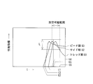
- FIG. 3 is a graph showing the relationship between the vulcanization state (equivalent vulcanization degree) calculated based on the temperature data measured at each part of the tire and the elapsed time t in the tire vulcanization method of the present invention.
- FIG. 4 is a graph showing the relationship between vulcanization quality (performance index) and elapsed time t in each part of the tire in the tire vulcanization method of the present invention.
- FIG. 5 is a flowchart showing the process up to demolding during vulcanization in the tire vulcanization method of the present invention.
- FIG. 1 shows a vulcanizing apparatus 1 used in the tire vulcanizing method of the present invention, and shows a state where an unvulcanized tire G is pressed against a molding surface of a mold 2 by a bladder 3 during vulcanization.
- the mold 2 is composed of molds 21, 22 and 23.
- the tire G mainly includes a tread portion G1, a side portion G2, and a bead portion G3, and a surface that contacts the bladder 3 during vulcanization is an inner surface Ga, and a surface that contacts the mold 2 is an outer surface Gb.
- the surface temperatures at the locations representing the respective portions of the tread portion G1, the side portion G2, and the bead portion G3 are measured at two locations on the inner surface Ga and the outer surface Gb, for a total of six locations.
- the measurement points to be paired inside and outside the tire are preferably close to each other in geometric position, but may be replaced with any other measurement points as long as they are thermally similar portions showing an equivalent temperature course.
- the temperature at the same latitude can be regarded as a thermally similar portion showing an equivalent temperature course due to its symmetry.
- a slight shift in latitude can be regarded as a thermally similar portion showing an equivalent temperature course if the distance relationship with the heat source, the positional relationship, and the gauge thickness of the unvulcanized tire are the same.
- the temperature measurement mechanism at these measurement points P1a, P2a, and P3a is not particularly limited.
- a structure in which a temperature measurement device such as a thermocouple is disposed inside the bladder 3 can be employed.
- the bladder is made of rubber reinforced with carbon black like the tire, the thermal properties are the same as the unvulcanized tire, so the temperature inside the bladder is measured and the thickness of the bladder is taken into account.
- the temperature inside the bladder may cause a significant temperature difference between the upper and lower sides, so at least the height (meridian latitude) must be equal.
- the processing point temperature of the mold 2 during vulcanization is changed over time. taking measurement.
- the temperature measurement mechanism at these measurement points P1b, P2b, and P3b is not particularly limited.
- a cavity is provided inside the mold 2, and a temperature sensing portion (for example, it is possible to adopt a structure in which a temperature measuring device such as a thermocouple is disposed so that the contact point of the thermocouple is not thermally influenced by the mold temperature and directly contacts the tire surface.
- a temperature measuring device such as a thermocouple
- the temperature measuring mechanism it becomes possible to measure the temperatures of the inner surface Ga and the outer surface Gb in each part of the tire G without damaging the tire G, It is suitable when manufacturing a tire product.
- the temperature and the degree of progress of the cross-linking reaction are shown at a portion belonging to a portion where vulcanization is most likely to be delayed at the time of vulcanization, that is, a so-called slowest vulcanization portion at a substantially central portion in the thickness direction of tire G
- the position of the substantially central portion in the thickness direction of the tire G is, for example, a substantially midpoint of a line segment connecting the measurement point P1a of the inner surface Ga of the tire G and the measurement point P1b of the outer surface Gb in the tread portion G1. And can be regarded as the midpoint P1c shown in FIG.
- the respective midpoints are P2c and P3c. That is, the temperature and the equivalent vulcanization degree at the midpoints P1c, P2c, and P3c located at the approximate center in the thickness direction of the tire G are estimated.
- initial conditions initial temperature of the tire G
- temperatures of the inner surface Ga of the tire G processing of the bladder 3 at the measurement points P1a, P2a, and P3a
- the temperature equation of the outer surface Gb is set as boundary conditions
- the heat conduction equation is numerically solved.
- various methods for numerically solving the heat conduction equation For example, based on the boundary conditions, the thickness of the tire G, and the thermal diffusion coefficient of the tire G, the Fourier heat conduction equation is numerically expressed using commercially available software.
- the difference equation can be solved using spreadsheet software (for example, Excel (registered trademark)).
- Excel registered trademark
- the temperature at each of the midpoints P1c, P2c, and P3c can be calculated by numerically solving the heat conduction equation by any of the methods described above.
- the equivalent degree of vulcanization means the amount of vulcanization reaction as is well known. Since the vulcanization speed changes if the vulcanization temperature is different, the vulcanization speed for each vulcanization temperature is obtained, multiplied by time, and calculated by time integration.
- the vulcanization reaction rate constant K indicating the vulcanization rate is calculated by the following equation (1).
- K A ⁇ exp ⁇ ? E / (R ⁇ T) ⁇ (1)
- A is a constant specific to rubber
- E is an activation energy
- R is a gas constant
- T a vulcanization temperature.
- the temperatures of the inner surface Ga and the outer surface Gb of a plurality of portions of the tire G are measured, and the temperature of the cross section of the tire G and the equivalent vulcanization based on the temperature data.
- the degree of vulcanization it is possible to grasp the vulcanized state of the tire G with high accuracy.
- FIG. 3 shows the relationship between the vulcanization state (equivalent vulcanization degree) calculated based on the temperature data measured at each part of the tire G and the elapsed time t.
- the vertical axis represents the equivalent vulcanization degree
- the horizontal axis represents the elapsed time t (minutes).
- each part of the tread part G1, the side part G2, and the bead part G3 of the tire G has a tread part G1 according to a difference in surface temperature, thickness, and thermal diffusivity for each part as vulcanization proceeds.
- the side part G2 and the bead part G3 generally have different equivalent vulcanization degrees.
- the vulcanization time to reach the quality is also different.
- the equivalent vulcanization degree gradually increases as vulcanization progresses, and reaches an equivalent vulcanization degree that satisfies the quality required for the tread portion G1 at a certain point in time.
- the time when the required quality is satisfied is t1, and the quality required for the tread portion G1 is reduced by demolding after the time t1 (the thick line portion of the equivalent vulcanization degree curve shown in FIG. 3). A filled tire G is obtained.
- the equivalent vulcanization degree that satisfies the optimum quality in the tread portion G1 is reached.
- the time when the optimum quality in the tread portion G1 is satisfied is t t , and the tire having the optimum vulcanization quality in the tread portion G1 can be obtained by demolding at the time t t .
- the case of the side part G2 and the bead part G3 is the same as the above-described tread part G1, and the time points t2 and t3 indicate the time points satisfying the quality required for each part, and the time points t s and t b are optimum values in each part. Indicates the point in time when the quality is satisfied. By demolding at time points t s and t b , a tire having optimum vulcanization quality in the side portion G2 and the bead portion G3 can be obtained.
- the time when all the qualities required for the tread part G1, the side part G2, and the bead part G3 of the tire G are satisfied is the time when the vulcanization time can be shortened most and the productivity is the best.
- the longest elapsed time t among the time points t1, t2, and t3 that satisfy the required quality of each part of the tire G is the time point t1 of the tread portion G1. Therefore, the time point t1 that satisfies the required quality of the tread portion G1 is the most preferable time point from the viewpoint of productivity.
- the time point after t1 is a demoldable range, and when demolding in that range, it means that the productivity of the tire G is secured.
- an appropriate vulcanization state index that can be accepted as a product is specified based on the quality required for each part of the tire G, and all the vulcanization states based on the temperature data of each part of the tire G satisfy the index.
- FIG. 4 shows the relationship between the vulcanization quality (performance index) of each part of the tire G calculated based on the temperature data and the elapsed time t.
- the performance index shown in FIG. 4 is premised on a tire that satisfies the quality required in each part of the tire described above, and the vulcanization quality at each elapsed time is not achieved with respect to the level that should be satisfied at the minimum. It is an index that shows whether it is present or exceeded.
- the vertical axis is the performance index
- the horizontal axis is the elapsed time t (minutes).
- the time to reach the quality is also different. For example, as described with reference to FIG. 3, in the tread part G1, after the start of vulcanization, the required quality of the tread part G1 is not reached until a certain amount of time has elapsed, so the value of the performance index remains zero. Thereafter, the performance index curve moves upward from time t1 when the required quality of the tread portion G1 is reached, and reaches a peak at time t t when the optimum quality is satisfied. Further vulcanization proceeds, and after time t t , the vulcanization quality of the tread portion G1 gradually decreases.
- the side part G2 and the bead part G3 are the same as the tread part G1, and the performance index curve changes to the right from the time point t2 and t3 when the required quality is reached, and the time point t s , It peaked at t b, the time t s, vulcanized quality of t b later become the side portion G2 and the bead portion G3 gradually decreases. This decrease in vulcanization quality is partly due to deterioration of rubber quality due to overvulcanization.
- L be the acceptable performance range that satisfies the performance required in the design of the tire.
- the tread part G1 is the slowest to reach the performance range L, and the time when the performance index curve first reaches the lower limit of the performance range L is t4.
- the time point when the lower limit of the performance range L is reached is set as t6. Even if the quality required for each part of the tire is satisfied, it is not preferable to remove the mold if the performance required by the design of the tire is not satisfied.
- the performance index curve of the tread portion G1 that is the slowest to reach the performance range L satisfies the performance range L, that is, between t4 and t6, the quality required for the tread portion G1 is satisfied, and the performance range
- the range of the vulcanization time satisfying L is meant, and the range of the vulcanization time that can be demolded is meant.
- the time points at which the performance indexes of the tread portion G1, the side portion G2, and the bead portion G3 are harmonized.
- t5 By removing the mold at this time t5, it is possible to obtain a tire that is most balanced in the performance indexes of all the parts of the tire.
- the balance and harmony may be determined by the combination of the conditions in which the tires are used, i.e., the operating conditions of the vehicle equipped with the tires. In the case of taxis and private cars owned by Sunday drivers, the former The wear performance is more likely to increase the value of use when the latter places importance on the side UV degradation performance, which leads to customer benefits.
- vulcanization information related to matters prioritized in specifying the index is coded in this way, and the coded priorities are recorded in the vulcanized tire as tire attributes.
- the coded priorities are recorded in the vulcanized tire as tire attributes.
- the time of demolding is determined by giving priority to productivity (when time t4 is set as the time of demolding), as shown in Table 1, the incidental The cord is “P” and the accompanying cord is given to the tire.
- a QR code registered trademark
- vulcanization information related to matters prioritized in determining the timing of demolding at the time of vulcanization is coded and given as an incidental code to the tire, so that performance in needs such as operation of a vehicle equipped with a tire is demonstrated.
- a tire that prioritizes more preferable performance it is possible to ensure an increase in utility value for each tire.
- step S1 the processing point temperature of the bladder 3 is measured at the measurement points P1a, P2a, P3a of the inner surface Ga of each part of the tread portion G1, the side portion G2, and the bead portion G3 of the tire G, and the outer surface Gb
- the processing point temperature of the mold 2 is measured at the measurement points P1b, P2b, and P3b.
- step S2 using the temperature data measured in step S1, the temperature and equivalent vulcanization degree at the midpoints P1c, P2c, and P3c located at the center in the thickness direction of the tire G are calculated using the calculation method described above. calculate.
- step S3 the vulcanization state of the tire G based on the temperature and equivalent vulcanization degree at the midpoints P1c, P2c, and P3c obtained in step S2 is based on the quality or productivity required for each part of the tire. Determine whether the indicator is met. If it is determined that the index is satisfied, the process proceeds to step S4. On the other hand, if it is determined that the index is not satisfied, the process returns to step S1.
- step S4 a demoldable time point at the time of vulcanization is determined, and demolding is performed in the vulcanizer 1. As described above, it is possible to determine the timing of demolding the tire G during vulcanization.
Landscapes
- Engineering & Computer Science (AREA)
- Mechanical Engineering (AREA)
- Physics & Mathematics (AREA)
- Health & Medical Sciences (AREA)
- Oral & Maxillofacial Surgery (AREA)
- Thermal Sciences (AREA)
- Moulds For Moulding Plastics Or The Like (AREA)
- Heating, Cooling, Or Curing Plastics Or The Like In General (AREA)
Abstract
加硫状態の揃ったタイヤを、殊に金型温度の浮動する状況下でも効率よく生産するために、タイヤを傷つけることなく脱型の時期までタイヤの内表面及び外表面の温度を測定し、その測定した温度データに基づいてタイヤの加硫状態を高い精度で把握することにより、タイヤ毎に最適な加硫操作を実現することを可能にしたタイヤ加硫方法を提供する。タイヤGの加硫中に、タイヤGを代表する複数の主要な部位における内表面及び外表面の温度を測定し、これら測定された温度データに基づいて計算された、架橋反応の進行度を示す等価加硫度に応じて脱型の時期を決める。
Description
本発明は、タイヤ加硫方法に関し、更に詳しくは、加硫状態の揃ったタイヤを、殊に金型温度の浮動する状況下でも効率よく生産するために、タイヤを傷つけることなく脱型の時期までタイヤの内表面及び外表面の温度を測定し、その測定した温度データに基づいてタイヤの加硫状態を高い精度で把握することにより、タイヤ毎に最適な加硫操作を実現することを可能にしたタイヤ加硫方法に関する。
タイヤを加硫する際に加硫状態の揃った良好な加硫品質を得るため、タイヤ毎に加硫速度に影響する主たる因子を把握し、それらの影響を加味して、例えば、1本毎に加硫時間を調節して、個々のタイヤに適した加硫操作を実施し、ロットを構成するタイヤの品質を均質化することが行われている。このタイヤ毎の加硫操作は、加硫されるタイヤの各部位の温度を加硫の最中に精度良く把握することが重要である。
加硫中のタイヤの温度を測定するために、無線発信機付きの温度センサチップを加硫前のタイヤの所望する温度測定箇所に予め埋設し、温度センサチップにより、温度測定箇所における温度データを取得することが提案されている(例えば、特許文献1)。しかしながら、200℃近くまで温度上昇するタイヤに埋め込まれ、温度を測りそれを無線信号で金型外部に通信する機能を持つチップや、加硫機に付帯する受信システムは、技術的にもコスト的にもハードルが高い上、温度センサチップをタイヤに埋設することで、タイヤに傷や耐久性を悪化させる可能性のある異物を残すという問題がある。
また、加硫中のタイヤ内部の温度分布を把握する方法として、ジャケット、金型及びブラダーの温度に基づいて、解析モデルによりタイヤ内部の温度を推定し、その推定された温度から最遅点を決定することが提案されている(例えば、特許文献2)。しかしながら、タイヤ表面から離れた箇所で測定された温度に基づき、しかも金型とゴムの間の言わば熱的に非連続な界面を介してタイヤ内部の温度を推定するため、この非連続な界面の性質が高温の影響などで変化すると、十分な精度で加硫状態を把握し続けることができないという問題がある。
本発明の目的は、タイヤを傷つけることなく加硫プレス中の最初から最後までタイヤの内表面及び外表面の温度を測定し、その測定した温度データに基づいてタイヤの加硫状態を十分な精度で把握することにより、タイヤ毎に最適な加硫操作を実現することを可能にしたタイヤ加硫方法を提供することにある。
上記目的を達成するための本発明のタイヤ加硫方法は、タイヤの加硫中に、該タイヤを代表する複数の主要な部位における内表面及び外表面の温度を測定し、これら測定された温度データに基づいて計算された、架橋反応の進行度を示す等価加硫度に応じて脱型の時期を決めることを特徴とするものである。
本発明では、タイヤの加硫中に、タイヤを代表する複数の主要な部位の内表面及び外表面の温度を継続的に測定し、その温度データに基づいてタイヤ断面の温度及び等価加硫度を計算することで、タイヤを損傷することなく、タイヤの加硫状態を十分な精度で把握することができる。そのタイヤの加硫状態に応じて加硫時における脱型の時期を決定することにより、タイヤ毎に最適な加硫操作を実現することが可能となる。
本発明では、タイヤの各部位に要求される品質に基づいて製品として受容できる適正な加硫状態の指標を特定し、タイヤの各部位の温度データに基づく加硫状態のすべてが指標を満たしたときを脱型の時期とすることが好ましい。トレッド部、サイド部及びビード部の各部位が最良の加硫状態となる時期は必ずしも一致しないが、タイヤ全体として最良の品質となるように各部位の品質バランスを見て加硫状態の指標を特定して加硫時における脱型の時期を決定することにより、タイヤ全体として最良の品質であると共にタイヤの各部位における適正な加硫品質を有するタイヤを得ることができる。
本発明では、加硫時における脱型の時期を決定するのに際して優先された事項に関する加硫情報をコード化し、タイヤに付与することが好ましい。このように加硫時における脱型の時期を決定するに際して優先された事項に関する加硫情報をタイヤ属性として記録することで、タイヤを装着する車両の運用などのニーズにおける性能発揮に対して、より好ましい性能を優先したタイヤを選択することで、タイヤの利用価値の増進を担保することができる。
以下、本発明の構成について添付の図面を参照しながら詳細に説明する。図1は本発明のタイヤ加硫方法で使用される加硫装置1を示すものであり、加硫時にブラダー3により未加硫のタイヤGを金型2の成形面に押し付けている状態を示している。金型2は、金型21,22,23から構成されている。タイヤGは主にトレッド部G1、サイド部G2及びビード部G3からなり、加硫時に、ブラダー3と当接する面が内表面Gaであり、金型2と当接する面が外表面Gbである。
タイヤGの加硫中に、少なくともトレッド部G1、サイド部G2及びビード部G3の各部位を代表する箇所における表面温度を、内表面Ga及び外表面Gbのそれぞれ2箇所、計6箇所において測定する。タイヤ内外の対となる測定点は、幾何学的位置が互いに近接することが好ましいが、同等の温度経過を示す熱的に類似する箇所であれば、これに代えても良い。これは、例えば、タイヤ上の位置を子午線で表す時に、同緯度の温度はその対称性から同等の温度経過を示す熱的に類似する箇所と見做し得る。緯度の多少のずれも、熱源との距離関係や位置的関係や未加硫タイヤのゲージ厚さが同等であれば、同等の温度経過を示す熱的に類似する箇所と見做し得る。
図2に示すように、トレッド部G1、サイド部G2及びビード部G3の各部位におけるタイヤGの内表面Gaに位置する測定点P1a,P2a,P3aにおいて、加硫中のブラダー3の加工点温度を経時的に測定する。これら測定点P1a,P2a,P3aでの温度測定機構が特に限定されるものではないが、例えば、ブラダー3の内部に熱電対等の温度測定機器を配設するようにした構造を採用することができる。また、ブラダーはタイヤと同じくカーボンブラックで補強されたゴムで構成されているので、熱的性質は未加硫タイヤと同質故に、ブラダー内面の温度を測定し、ブラダーの厚さを加味してタイヤ内面の温度を推定することも可能である。但し、この場合でも、ブラダー内部の温度は窒素ガスと水蒸気の混合熱媒体を用いるときには上下に顕著な温度差を生じることがあるので、少なくとも高さ(子午線緯度)は同等であることが必要となる。一方、トレッド部G1、サイド部G2及びビード部G3の各部位におけるタイヤGの外表面Gbに位置する測定点P1b,P2b,P3bにおいて、加硫中の金型2の加工点温度を経時的に測定する。これら測定点P1b,P2b,P3bでの温度測定機構が特に限定されるものではないが、例えば、金型2の内部に空洞を設け、該空洞内に、遮熱ゾーンを介して感温部(例えば熱電対の接点)が熱的に金型温度の影響を受けがたく、かつ直接的にタイヤ表面と接するように熱電対等の温度測定機器を配設した構造を採用することができる。このように金型2及びブラダー3の内部に温度測定機構を設けることにより、タイヤGを損傷することなくタイヤGの各部位における内表面Ga及び外表面Gbの温度を測定することが可能となり、タイヤ製品の製造時において好適である。
本発明では、加硫時に最も加硫の遅れる可能性のある部位に属する箇所、所謂、最遅加硫箇所であるタイヤGの厚さ方向の略中央部における温度及び架橋反応の進行度を示す等価加硫度を推定する。このタイヤGの厚さ方向の略中央部の位置は、例えば、トレッド部G1において、タイヤGの内表面Gaの測定点P1aと、外表面Gbの測定点P1bとを結ぶ線分の略中点であり、図2に示す中点P1cと見做すことができる。サイド部G2及びビード部G3においても、同様に、それぞれの中点をP2c,P3cとする。即ち、タイヤGの厚さ方向の略中央部に位置する中点P1c,P2c,P3cにおける温度及び等価加硫度を推定する。
加硫時の中点P1c,P2c,P3cにおける温度の推定する場合、初期条件(タイヤGの初期温度)、タイヤGの内表面Gaの温度(測定点P1a,P2a,P3aでのブラダー3の加工点温度)及び外表面Gbの温度(測定点P1b,P2b,P3bでの金型2の加工点温度)を境界条件として設定し、熱伝導方程式を数値的に解く方法がある。この熱伝導方程式を数値的に解く方法は種々あり、例えば、上述する境界条件、タイヤGの厚さ及びタイヤGの熱拡散係数に基づいて市販のソフト等を用いてフーリエの熱伝導方程式を数値的に解くことができる。或いは、熱伝導方程式から差分方程式を作成して、シュミット法と呼ばれる図形解法をコンピュータに実行させる方法がある。この場合、例えば、表計算用のソフトウェア(例えばエクセル(登録商標))等を用いて差分方程式を解くことができる。上述するいずれかの方法により熱伝導方程式を数値的に解くことで、中点P1c,P2c,P3cの各点における温度を算出することができる。
等価加硫度とは周知のとおり加硫反応量を意味する。加硫温度が異なれば加硫速度が変化するため、加硫温度毎の加硫速度を求めてこれに時間を乗じ、時間積分することで算出される。加硫速度を示す加硫反応速度定数Kは、以下の(1)式によって算出される。
K=A・exp{?E/(R・T)}・・・(1)
Aはゴム特有の定数、Eは活性化エネルギー、Rは気体定数、Tは加硫温度である。
K=A・exp{?E/(R・T)}・・・(1)
Aはゴム特有の定数、Eは活性化エネルギー、Rは気体定数、Tは加硫温度である。
上記タイヤ加硫方法において、タイヤGの加硫中に、タイヤGの複数の部位の内表面Ga及び外表面Gbの温度を測定し、その温度データに基づいてタイヤGの断面の温度及び等価加硫度を算出することで、タイヤGの加硫状態を高い精度で把握することが可能となる。
図3はタイヤGの各部位で測定された温度データに基づいて計算された加硫状態(等価加硫度)と経過時間tの関係を示すものである。縦軸は等価加硫度、横軸は経過時間t(分)である。図3に示すように、タイヤGのトレッド部G1、サイド部G2及びビード部G3の各部位は、加硫が進むにつれて部位毎の表面温度や厚みや熱拡散率の違いに応じてトレッド部G1、サイド部G2、ビード部G3は一般に異なる等価加硫度を有する。
タイヤGの各部位において要求される品質及び使用される未加硫ゴムはそれぞれ異なるため、その品質に達する加硫時間もそれぞれ異なる。例えば、トレッド部G1の場合、加硫が進むにつれて徐々に等価加硫度は上昇していき、ある時点においてトレッド部G1に要求される品質を満たす等価加硫度に達する。その要求される品質を満たす時点がt1であり、この時点t1の以降(図3に示す等価加硫度曲線の太線部)の時点で脱型することにより、トレッド部G1に要求される品質を満たしたタイヤGが得られる。更に時点t1から加硫が進むと、トレッド部G1における最適な品質を満たす等価加硫度に達する。このトレッド部G1における最適な品質を満たす時点がttであり、この時点ttで脱型することにより、トレッド部G1における最適な加硫品質を有するタイヤを得ることができる。
サイド部G2及びビード部G3の場合も上述するトレッド部G1と同様であり、時点t2,t3は各部位に要求される品質を満たす時点を示し、時点ts,tbは各部位における最適な品質を満たす時点を示している。時点ts,tbで脱型することにより、サイド部G2、ビード部G3における最適な加硫品質を有するタイヤを得ることができる。
一方、加硫時間を可及的に短くすることは、タイヤの生産性の観点から好ましい。そのため、タイヤGのトレッド部G1、サイド部G2及びビード部G3に要求される品質を全て満たした時点が、最も加硫時間を短くできる時点であり、かつ生産性が最も良い時点となる。図3において、タイヤGの各部位の要求される品質を満たす時点t1,t2,t3のうち最も経過時間tが長いのは、トレッド部G1の時点t1である。従って、トレッド部G1の要求される品質を満たす時点t1が、生産性の観点からは最も好ましい時点となる。また、生産性の観点からは時点t1以降が脱型可能な範囲であり、その範囲において脱型した場合はタイヤGの生産性が担保された状態であることを意味する。
このようにタイヤGの各部位に要求される品質に基づいて製品として受容できる適正な加硫状態の指標を特定し、タイヤGの各部位の温度データに基づく加硫状態のすべてが指標を満たしたときを脱型の時期とすることで、タイヤG全体として最良の品質であると共にタイヤGの各部位における適正な加硫品質を有するタイヤを得ることができる。
図4は温度データに基づき計算されたタイヤGの各部位の加硫品質(性能指標)と経過時間tの関係を示すものである。図4に示す性能指標は、上述するタイヤの各部位において要求される品質を満たすタイヤを前提とするものであり、最低限満たすべき水準に対して、各経過時間における加硫品質が未達であるか、上回っているかを分かり易く示した指標である。縦軸は性能指標、横軸は経過時間t(分)である。
タイヤGの各部位において最適な品質を満たす時点はそれぞれ異なるため、その品質に達する時間もそれぞれ異なる。例えば、図3で説明した様に、トレッド部G1において、加硫開始後、ある程度の時間が経過するまでトレッド部G1の要求される品質に達しないため性能指標の値がゼロのまま推移する。その後、トレッド部G1の要求される品質に達した時点t1から性能指標曲線が右上がりに推移していき、最適な品質を満たす時点ttでピークを迎える。更に加硫が進み、時点tt以降になるとトレッド部G1の加硫品質は徐々に低下していく。サイド部G2及びビード部G3においてもトレッド部G1と同様であり、要求される品質に達した時点t2,t3から性能指標曲線が右上がりに推移していき、最適な品質を満たす時点ts,tbでピークを迎え、時点ts,tb以降になるとサイド部G2及びビード部G3の加硫品質は徐々に低下していく。こうした加硫品質の低下は、過加硫によるゴム品質の劣化などが一因である。
ここで、図4に示すように、タイヤの設計上要求される性能を満足し、受け入れ可能な性能範囲をLとする。トレッド部G1、サイド部G2及びビード部G3のうち、この性能範囲Lに達するのが最も遅いのはトレッド部G1であり、その性能指標曲線が最初に性能範囲Lの下限に達する時点をt4とし、次に性能範囲Lの下限に達する時点をt6とする。たとえ、タイヤの各部位に要求される品質を満たしていても、タイヤの設計上要求される性能を満たしていない場合に脱型することは好ましくない。そのため、性能範囲Lに達するのが最も遅いトレッド部G1の性能指標曲線が性能範囲Lを満たしている間、即ち、t4~t6の間がトレッド部G1に要求される品質を満たし、かつ性能範囲Lを満たす加硫時間の範囲となり、脱型可能な加硫時間の範囲を意味する。
また、性能範囲Lを担保した上で脱型することが可能となる加硫時間の範囲t4~t6において、トレッド部G1、サイド部G2及びビード部G3の性能指標の調和が取れている時点をt5とする。この時点t5で脱型することにより、タイヤの全ての部位の性能指標において最もバランスの取れたタイヤを得ることができる。バランスや調和の良し悪しは、タイヤを使用する状況、即ち、そのタイヤを装着した車両の運用状況との組み合わせで判断される場合もあり、タクシーとサンデードライバーの保有する自家用車とでは、前者が摩耗性能を、後者がサイドの紫外線劣化性能を重視した方が、使用価値が増大する蓋然性が高く顧客の利益に繋がるものである。
本発明では、このように指標の特定に際して優先された事項に関する加硫情報をコード化し、そのコード化された優先事項をタイヤ属性として加硫されたタイヤに記録する。優先事項に関する加硫情報をコード化する際、例えば、生産性を優先させて脱型の時期を決定した場合(時点t4を脱型の時期とした場合)、表1に示すように、その付帯コードは「P」であり、その付帯コードをタイヤに付与する。タイヤに付帯コードを付与する方法として、例えば、QRコード(登録商標)を利用することができる。

このように加硫時における脱型の時期を決定するのに際して優先された事項に関する加硫情報をコード化しタイヤに付帯コードとして付与することで、タイヤを装着する車両の運用などのニーズにおける性能発揮に対して、より好ましい性能を優先したタイヤを選択することで、タイヤ毎の利用価値の増進を担保することができる。
上記加硫装置1を用いてタイヤGを加硫する場合、加硫中に脱型の時期を決定するまでの過程について、図5を参照して説明する。先ず、ステップS1において、タイヤGのトレッド部G1、サイド部G2及びビード部G3の各部位の内表面Gaの測定点P1a,P2a,P3aでブラダー3の加工点温度を測定し、外表面Gbの測定点P1b,P2b,P3bで金型2の加工点温度を測定する。
次いで、ステップS2において、ステップS1で測定した温度データを利用してタイヤGの厚さ方向中央部に位置する中点P1c,P2c,P3cにおける温度及び等価加硫度を上述する計算方法を用いて算出する。
次いで、ステップS3において、ステップS2で得られた中点P1c,P2c,P3cにおける温度及び等価加硫度に基づくタイヤGの加硫状態が、タイヤの各部位に要求される品質又は生産性に基づく指標を満たしているか否かを判断する。指標を満たしていると判断した場合はステップS4に進む。一方、指標を満たしていないと判断した場合はステップS1に戻る。
そして、ステップS4において、加硫時における脱型可能な時点が決定し、加硫装置1において脱型を行う。以上により、加硫時においてタイヤGの脱型の時期を決定することができる。
1 加硫装置
2 金型
3 ブラダー
G タイヤ
G1 トレッド部
G2 サイド部
G3 ビード部
Ga 内表面
Gb 外表面
2 金型
3 ブラダー
G タイヤ
G1 トレッド部
G2 サイド部
G3 ビード部
Ga 内表面
Gb 外表面
Claims (3)
- タイヤの加硫中に、該タイヤを代表する複数の主要な部位における内表面及び外表面の温度を測定し、これら測定された温度データに基づいて計算された、架橋反応の進行度を示す等価加硫度に応じて脱型の時期を決めることを特徴とするタイヤ加硫方法。
- 前記タイヤの各部位に要求される品質又は生産性に基づいて製品として受容できる適正な加硫状態の指標を特定し、前記タイヤの各部位の前記温度データに基づく加硫状態のすべてが前記指標を満たしたときを脱型の時期とすることを特徴とする請求項1に記載のタイヤ加硫方法。
- 加硫時における前記脱型の時期を決定するのに際して優先された事項に関する加硫情報をコード化し、前記タイヤに付与することを特徴とする請求項1又は2に記載のタイヤ加硫方法。
Priority Applications (2)
| Application Number | Priority Date | Filing Date | Title |
|---|---|---|---|
| US16/095,319 US11077634B2 (en) | 2016-04-19 | 2017-03-31 | Tire vulcanizing method |
| CN201780023926.4A CN109070400A (zh) | 2016-04-19 | 2017-03-31 | 轮胎硫化方法 |
Applications Claiming Priority (2)
| Application Number | Priority Date | Filing Date | Title |
|---|---|---|---|
| JP2016-083489 | 2016-04-19 | ||
| JP2016083489A JP6801215B2 (ja) | 2016-04-19 | 2016-04-19 | タイヤ加硫方法 |
Publications (1)
| Publication Number | Publication Date |
|---|---|
| WO2017183422A1 true WO2017183422A1 (ja) | 2017-10-26 |
Family
ID=60116658
Family Applications (1)
| Application Number | Title | Priority Date | Filing Date |
|---|---|---|---|
| PCT/JP2017/013568 Ceased WO2017183422A1 (ja) | 2016-04-19 | 2017-03-31 | タイヤ加硫方法 |
Country Status (4)
| Country | Link |
|---|---|
| US (1) | US11077634B2 (ja) |
| JP (1) | JP6801215B2 (ja) |
| CN (1) | CN109070400A (ja) |
| WO (1) | WO2017183422A1 (ja) |
Families Citing this family (2)
| Publication number | Priority date | Publication date | Assignee | Title |
|---|---|---|---|---|
| IT201900024970A1 (it) * | 2019-12-20 | 2021-06-20 | Pirelli | Processo ed apparato di vulcanizzazione per pneumatici |
| CN117207569A (zh) * | 2023-09-12 | 2023-12-12 | 浙江迪马橡胶有限公司 | 一种一体硫化免充气橡胶轮胎的生产工艺 |
Citations (5)
| Publication number | Priority date | Publication date | Assignee | Title |
|---|---|---|---|---|
| JPS5993338A (ja) * | 1982-11-18 | 1984-05-29 | Sumitomo Rubber Ind Ltd | ゴム製品のデ−タ表示方法 |
| JPS6013250A (ja) * | 1983-07-01 | 1985-01-23 | Bando Chem Ind Ltd | ゴム加硫工程の制御方法 |
| JP2005212150A (ja) * | 2004-01-27 | 2005-08-11 | Yokohama Rubber Co Ltd:The | 等価加硫度の予測方法及び等価加硫度の予測用コンピュータプログラム、並びにゴム製品の製造方法 |
| JP2015101005A (ja) * | 2013-11-26 | 2015-06-04 | 住友ゴム工業株式会社 | タイヤ加硫温度の測定方法 |
| JP2015223755A (ja) * | 2014-05-27 | 2015-12-14 | 株式会社ブリヂストン | タイヤ加硫金型、及びタイヤ加硫金型の製造方法 |
Family Cites Families (14)
| Publication number | Priority date | Publication date | Assignee | Title |
|---|---|---|---|---|
| GB1165671A (en) * | 1966-03-24 | 1969-10-01 | Dunlop Co Ltd | Improvements in or relating to the Curing of Rubber or Plastics Articles. |
| JPS599333A (ja) * | 1982-07-05 | 1984-01-18 | Matsushita Electric Ind Co Ltd | 密閉形回転圧縮機の吸振装置 |
| US5055245A (en) | 1986-07-07 | 1991-10-08 | Bridgestone Corporation | Method of measuring temperature within cured article and method of controlling tire vulcanization |
| JPS63139708A (ja) * | 1986-12-02 | 1988-06-11 | Bridgestone Corp | タイヤの加硫制御方法およびその装置 |
| JPS63111017A (ja) * | 1986-10-28 | 1988-05-16 | Bridgestone Corp | タイヤの加硫制御方法 |
| JPS6315708A (ja) * | 1986-07-07 | 1988-01-22 | Bridgestone Corp | タイヤ加硫の制御方法 |
| JPS6317010A (ja) * | 1986-07-08 | 1988-01-25 | Bridgestone Corp | タイヤ加硫の制御方法 |
| JPH0740355A (ja) * | 1993-07-26 | 1995-02-10 | Bridgestone Corp | 加硫制御方法 |
| DE60013209T2 (de) * | 1999-07-14 | 2005-09-01 | Pirelli Pneumatici S.P.A. | Verfahren zum Vulkanisieren eines Reifens durch Bestimmung seines Vulkanisationsgrades |
| JP2005271534A (ja) * | 2004-03-26 | 2005-10-06 | Yokohama Rubber Co Ltd:The | 空気入りタイヤの加硫方法 |
| BRPI0520581B1 (pt) * | 2005-10-27 | 2017-03-28 | Pirelli | método e aparelho para vulcanizar pneus pneumáticos |
| JP5362263B2 (ja) * | 2008-06-20 | 2013-12-11 | 住友ゴム工業株式会社 | タイヤ加硫装置 |
| JP5737331B2 (ja) | 2013-05-27 | 2015-06-17 | 横浜ゴム株式会社 | 加硫制御方法および加硫制御システム |
| US10377060B2 (en) | 2014-05-27 | 2019-08-13 | Bridgestone Corporation | Mold, tire curing mold, and method for manufacturing mold |
-
2016
- 2016-04-19 JP JP2016083489A patent/JP6801215B2/ja active Active
-
2017
- 2017-03-31 US US16/095,319 patent/US11077634B2/en not_active Expired - Fee Related
- 2017-03-31 WO PCT/JP2017/013568 patent/WO2017183422A1/ja not_active Ceased
- 2017-03-31 CN CN201780023926.4A patent/CN109070400A/zh active Pending
Patent Citations (5)
| Publication number | Priority date | Publication date | Assignee | Title |
|---|---|---|---|---|
| JPS5993338A (ja) * | 1982-11-18 | 1984-05-29 | Sumitomo Rubber Ind Ltd | ゴム製品のデ−タ表示方法 |
| JPS6013250A (ja) * | 1983-07-01 | 1985-01-23 | Bando Chem Ind Ltd | ゴム加硫工程の制御方法 |
| JP2005212150A (ja) * | 2004-01-27 | 2005-08-11 | Yokohama Rubber Co Ltd:The | 等価加硫度の予測方法及び等価加硫度の予測用コンピュータプログラム、並びにゴム製品の製造方法 |
| JP2015101005A (ja) * | 2013-11-26 | 2015-06-04 | 住友ゴム工業株式会社 | タイヤ加硫温度の測定方法 |
| JP2015223755A (ja) * | 2014-05-27 | 2015-12-14 | 株式会社ブリヂストン | タイヤ加硫金型、及びタイヤ加硫金型の製造方法 |
Also Published As
| Publication number | Publication date |
|---|---|
| US11077634B2 (en) | 2021-08-03 |
| JP6801215B2 (ja) | 2020-12-16 |
| JP2017193079A (ja) | 2017-10-26 |
| US20190134932A1 (en) | 2019-05-09 |
| CN109070400A (zh) | 2018-12-21 |
Similar Documents
| Publication | Publication Date | Title |
|---|---|---|
| US10131104B2 (en) | Vulcanization control method and vulcanization control system | |
| CN100567037C (zh) | 轮胎警报装置 | |
| US20130118660A1 (en) | Moulding element comprising a plurality of ribs and at least one rib-free measurement zone | |
| WO2017183422A1 (ja) | タイヤ加硫方法 | |
| EP3842206A1 (en) | Rubber temperature measuring device and method for manufacturing rubber product | |
| JP7306815B2 (ja) | タイヤ劣化推定システムおよびタイヤ劣化推定方法 | |
| US20180162177A1 (en) | Load derivation method | |
| JP5313054B2 (ja) | タイヤ用加硫装置 | |
| US20200156337A1 (en) | Temperature sensor, and method for producing pneumatic tire | |
| JP4730823B2 (ja) | 加硫制御方法及び制御システム | |
| JPH09239866A (ja) | 更生タイヤの判別方法及び更生タイヤの製造方法 | |
| JPH05162137A (ja) | タイヤの加硫制御方法 | |
| CN106163779B (zh) | 可脱模性预测模型 | |
| KR20130063224A (ko) | 적정 가류시간 설정을 위한 가류시간 예측장치 | |
| US10551279B2 (en) | Surface demoldability prediction model | |
| JP7469628B2 (ja) | 空気入りタイヤの製造方法及び製造装置 | |
| KR20100077672A (ko) | 차량용 공기입 타이어와 그 제조방법 | |
| KR20190067599A (ko) | 재생타이어의 제조방법 | |
| JP2013035421A (ja) | 空気入りタイヤおよび空気入りタイヤの更生方法 | |
| JP7678276B2 (ja) | タイヤの断面形状予測方法およびタイヤの製造方法 | |
| JP2007212278A (ja) | 旧ゴムゲージ測定機 | |
| JP7429546B2 (ja) | タイヤ成型用金型および空気入りタイヤの製造方法 | |
| CN121683035A (zh) | 一种可快速确定多规格轮胎硫化时间的方法 | |
| JP3987422B2 (ja) | タイヤの部材厚測定方法及びその装置 | |
| JP2019038110A (ja) | タイヤ加硫方法及びタイヤ加硫装置 |
Legal Events
| Date | Code | Title | Description |
|---|---|---|---|
| NENP | Non-entry into the national phase |
Ref country code: DE |
|
| 121 | Ep: the epo has been informed by wipo that ep was designated in this application |
Ref document number: 17785764 Country of ref document: EP Kind code of ref document: A1 |
|
| 122 | Ep: pct application non-entry in european phase |
Ref document number: 17785764 Country of ref document: EP Kind code of ref document: A1 |