WO2017183174A1 - Dispositif de ligature - Google Patents
Dispositif de ligature Download PDFInfo
- Publication number
- WO2017183174A1 WO2017183174A1 PCT/JP2016/062722 JP2016062722W WO2017183174A1 WO 2017183174 A1 WO2017183174 A1 WO 2017183174A1 JP 2016062722 W JP2016062722 W JP 2016062722W WO 2017183174 A1 WO2017183174 A1 WO 2017183174A1
- Authority
- WO
- WIPO (PCT)
- Prior art keywords
- shaft
- yarn
- ligature
- atrial appendage
- left atrial
- Prior art date
Links
Images


Classifications
-
- A—HUMAN NECESSITIES
- A61—MEDICAL OR VETERINARY SCIENCE; HYGIENE
- A61B—DIAGNOSIS; SURGERY; IDENTIFICATION
- A61B17/00—Surgical instruments, devices or methods, e.g. tourniquets
- A61B17/12—Surgical instruments, devices or methods, e.g. tourniquets for ligaturing or otherwise compressing tubular parts of the body, e.g. blood vessels, umbilical cord
Definitions
- the present invention relates to a ligation device.
- the base part of the left atrial appendage that is, the connection part with the heart has a substantially elliptical cross-sectional shape, and the opening size is about 30 mm in the longitudinal direction and about 10 mm in the lateral direction.
- the width of the left atrial appendage is about 45 mm or less.
- the left atrial appendage is present on the convex heart surface, and the shape of the left atrial appendage and heart varies from person to person.
- the ligating devices of Patent Documents 1 and 2 may take time to place the ligature loop at the base of the left atrial appendage.
- the present invention has been made in view of the above-described circumstances, and an object thereof is to provide an optimal ligation device when the left atrial appendage is present on a convex heart surface having a particularly small curvature.
- a ligature including a loopable portion that can be contracted, an elongated shaft, and fixed to a distal end of the shaft, the looped portion of the ligature is held in a releasable state.
- a thread expansion portion, and in a free state, the thread expansion portion extends along a deployment surface that intersects the longitudinal axis of the shaft, and the deployment surface is recessed in a direction opposite to the shaft.
- the elongated shaft is inserted into the body from the yarn expansion portion side through a sheath or the like penetrating from the lower part of the xiphoid process to the inside of the pericardium, and the yarn is expanded from the sheath end in the pericardium.
- the thread expansion part expands to a free state, and the looped part of the ligature thread that is held is expanded, and along the development surface that intersects the longitudinal axis of the shaft. It becomes the form which extends.
- the loop-shaped portion By placing the left atrial appendage inside the expanded loop-shaped portion and pushing the shaft, the loop-shaped portion can be disposed near the base of the left atrial appendage.
- the thread expansion portion since the thread expansion portion has a shape along the development surface that is curved so as to be concave in the direction opposite to the shaft, it has a convex curved surface shape on the surface of the heart to which the root of the left atrial appendage is connected. It is arranged along.
- the left atrial appendage arranged on the inner side can be ligated by releasing the loop-like portion of the ligature from the yarn expansion portion and contracting it.
- an optimal ligation device can be provided when the left atrial appendage is present on a convex heart surface having a particularly small curvature.
- the yarn extending portion includes a proximal end portion connected to the shaft and a distal end portion disposed at a position distant from the shaft, and the development surface is substantially the same along the proximal end portion.
- the 1st surface and 2nd surface which consist of a substantially plane which mutually cross
- the thread expansion portion can be placed along the surface of the heart having a convex curved surface shape.
- the left atrial appendage having a width of approximately 35 mm to 50 mm can usually be easily accommodated in the loop-shaped portion and ligated.
- the said thread expansion part may be provided with the substantially parallel parallel part which opened the substantially constant space
- a parallel part is arranged so as to sandwich the left atrial appendage having a flat shape, and the left atrial appendage can be tightened as soon as the ligature is released from the thread expansion part. Can be held.
- the said parallel part may have a longitudinal direction, and may curve to the longitudinal direction of the said expansion
- the said thread expansion part may be formed in substantially cyclic
- the said thread expansion part may incline with respect to the said longitudinal axis of the said shaft around the axis line extended to the front-end
- the roots on both sides of the left atrial appendage thickness direction that protrude from the heart surface and extend along the heart surface toward the apex are viewed from the shaft that is introduced along the heart surface into the pericardium from the apex side, It is arranged at a position separated in the front-rear direction by the thickness of the left atrial appendage.
- the loop of the ligature is easily arranged at the root of the left atrial appendage.
- FIG. 2 is an enlarged perspective view showing a yarn expansion portion of the ligating device of FIG. 1. It is a side view which shows the state which inserted the left atrial appendage in the thread expansion part of the ligation device of FIG. It is an enlarged view which shows the holding
- a ligation device 1 according to an embodiment of the present invention will be described below with reference to the drawings.
- the ligating device 1 according to the present embodiment is provided on an elongated cylindrical shaft 2, a thread expansion portion 3 fixed to the distal end of the shaft 2, and a proximal end side of the shaft 2.
- the operation unit 4 and a ligature 5 that is disposed through a through hole (not shown) formed through the shaft 2 in the longitudinal direction and pulled by the operation unit 4 are provided.
- the shaft 2 is inserted from the outside of the body to the inside of the pericardium via a sheath or the like (not shown) that penetrates from the lower part of the xiphoid process to the inside of the pericardium, and operates the proximal end of the shaft 2 arranged outside the body.
- a sheath or the like not shown
- it is made of a relatively hard material so that the position and posture of the thread expansion portion 3 fixed to the tip can be adjusted.
- the yarn expanding portion 3 includes, for example, a holding portion 6 formed in an approximately U shape by an elastic material such as resin, and a frame portion (base end) for fixing the U-shaped open end of the holding portion 6 to the shaft 2. Part) 7.
- the yarn expanding portion 3 has a substantially oval annular shape fixed to the tip of the shaft 2.
- one end (base end portion) of an oval longitudinal axis is fixed to the shaft 2. Further, the holding portion 6 of the yarn expanding portion 3 connects the two parallel portions 8 extending linearly from one end of the oval longitudinal axis to the other end side, and the tip end side of the parallel portion 8. And a distal end portion 9 which is curved.
- a plane (first surface) A formed by the two parallel portions 8 extends in a direction intersecting with the longitudinal axis B of the shaft 2 at an angle ⁇ 1 in a free state, as shown in FIG.
- a frame portion 7 is attached to the frame.
- the distal end portion 9 is along a plane (second surface) C that is inclined at an angle ⁇ 3 in a direction opposite to the shaft 2 with respect to the first surface A formed by the two parallel portions 8 in a free state. Is stretched to extend.
- the thread expansion part 3 has a form which curves so that it may become concave on the opposite side to the shaft 2 along the development
- the yarn expanding portion 3 is inclined at an angle ⁇ 2 in one direction around an axis parallel to the oval longitudinal axis.
- the parallel part 8 of the yarn expansion part 3 has a length of about 30 mm, and the tip part 9 inclined with respect to the parallel part 8 has a length of about 15 mm. Further, the interval between the parallel portions 8 is a constant interval of about 10 mm. Thereby, generally the left atrial appendage X which has a width of 45 mm or less can be easily inserted into the thread expansion portion 3.
- the ligature 5 is provided with a loop portion (loop portion) 5a formed by a knot (not shown) at one end.
- the loop-shaped portion 5a is configured to be contractible by pulling the other end of the ligature yarn 5.
- the holding portion 6 of the yarn expanding portion 3 is provided with a containing hole 10 that accommodates a part of the looped portion of the ligature yarn 5 over the entire length. Is provided with a slit 11 that opens radially inward of the yarn expansion portion 3.
- the slit 11 is closed so that the ligature 5 accommodated in the accommodation hole 10 does not fall off, and tension is applied to the ligature 5 by pulling the other end of the ligature 5, so that the loop-shaped portion 5 a is formed.
- the loop-shaped portion 5 a is drawn out of the accommodation hole 10 through the slit 11.
- the yarn expanding portion 3 holds the looped portion 5a of the ligature yarn 5 in the expanded state by being accommodated in the accommodating hole 10, and the left atrial appendage X can be easily inserted into the looped portion 5a. Can be done.
- the thread expansion portion passes through an inner hole of a sheath or the like inserted so as to penetrate from the lower part of the xiphoid process into the pericardium.
- the shaft 2 is inserted into the pericardium from the 3rd side.
- the yarn expanding portion 3 is straightened by elastic deformation by the inner hole wall surface of the sheath, and is constrained in a state where the interval between the two parallel portions 8 is also narrowed. Thereby, the inside of the inner hole of a thin sheath can be inserted toward the pericardium.
- the thread expansion portion 3 When the thread expansion portion 3 is exposed from the distal end opening of the sheath into the pericardium, the free state is released from the restraint by the inner wall of the inner hole of the sheath, so that the interval between the two parallel portions 8 is widened, and By the brazing of the frame portion 7, the first surface A formed by the two parallel portions 8 is inclined with respect to the longitudinal axis B of the shaft 2 at an angle ⁇ 1 in one direction. At this time, the tip 9 of the yarn expanding portion 3 also extends along the second surface C inclined at an angle ⁇ 3 in the direction opposite to the shaft 2 with respect to the first surface A by brazing the holding portion 6. To restore.
- the loop-shaped part 5 a of the ligature 5 held in the accommodation hole 10 of the holding part 6 is held in a state of being expanded to the same size as the holding part 6.
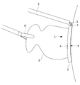
- the other end of the shaft 2 is operated outside the body to bring the thread expansion portion 3 close to the left atrial appendage X from the apex side, and the left atrial appendage X is inserted inside the holding portion 6 of the thread expansion portion 3. .
- the shaft 2 is pushed to push the thread expanding portion 3, thereby It can be placed near the base of the left atrial appendage X.
- the yarn expanding portion 3 is curved so as to be recessed in the opposite direction to the shaft 2 due to the first surface A and the second surface C intersecting each other.
- the loop-shaped portion 5a of the ligature 5 is disposed at a position closer to the root of the left atrial appendage X, as shown in FIG. Can be arranged.
- the root of the left atrial appendage X can be ligated by the loop-shaped portion 5a of the ligature 5 released from the yarn expansion portion 3.
- an optimal ligation device can be provided when the left atrial appendage is present on a convex heart surface having a particularly small curvature.
- the yarn expansion portion 3 is inclined at an angle ⁇ 2 with respect to the shaft 2 around an axis parallel to the longitudinal axis thereof, so that the shaft 2 has a shape as shown in FIG.
- one parallel portion 8 constituting the yarn expansion portion 3 is disposed on the near side, and the other parallel portion 8 is disposed on the back side.
- the parallel part 8 of the thread expansion part 3 at the tip of the shaft 2 arranged along the surface of the heart from the apex side can be brought close to the boundary between the left atrial appendage X and the heart surface.
- the loop-shaped portion 5a of the ligature 5 can be disposed at a position closer to the root of the atrial appendage X.
- the substantially U-shaped holding part 6 since the substantially U-shaped holding part 6 has accommodated the loop-shaped part 5a in the accommodation hole 10 over the entire circumference, the left atrial appendage X is inserted into the holding part 6.
- the loop portion 5a is not caught by the left atrial appendage X during operation, and the operation can be facilitated.
- the thread expansion portion 3 is formed in a substantially oval shape or a substantially rectangular shape by the two parallel portions 8 arranged substantially in parallel with a predetermined interval, the left atrial appendage X inserted between them Can be arranged at positions adjacent to each other in the thickness direction. Furthermore, since the inner diameter dimension of the longitudinal direction of the thread expansion portion 3 is set to about 35 mm to 50 mm, a general left atrial appendage X can be easily inserted, and it is greatly separated from the surface in the width direction of the inserted left atrial appendage X. The loop-shaped part of the front-end
- the loop-shaped portion 5a pulled out from the accommodation hole 10 through the slit 11 can perform ligation of the left atrial appendage.
- the thread expansion part 3 may have a form which curves so that it may bend along the expansion
- the thread expansion portion 3 is inclined with respect to the shaft 2 around the axis parallel to the longitudinal axis.
- the longitudinal axis B of the shaft 2 and the thread expansion It may be orthogonal to a plane including the longitudinal axis of the portion 3.
- the yarn extending portion 3 has an oval shape is illustrated, but instead, it may be formed in a substantially circular shape as shown in FIG.
- the parallel portions 8 arranged on the near side are arranged. It is necessary to arrange the shaft 2 so as to be arranged between the heart and the left atrial appendage X.
- the thread expansion portion 3 substantially circular, as shown in FIG. 8, the curved tip portion 9 is inserted between the heart and the left atrial appendage X, and the frame portion 7 is pushed by the force of pushing the shaft 2.
- the loop-shaped portion of the distal end portion 9 can be disposed at a position closer to the root of the left atrial appendage X.
Abstract
L'objet de la présente invention est de fournir un dispositif de ligature optimum dans un cas dans lequel l'appendice auriculaire gauche se trouve sur la surface du cœur ayant une forme convexe avec une courbure particulièrement faible. Ce dispositif (1) de ligature comprend : une ligature (5) qui comporte une partie sous forme de boucle pouvant se contracter ; une tige allongée (2) ; et une partie (3) provoquant l'expansion de la ligature qui est fixée à l'extrémité avant de la tige (2) et qui retient la ligature (5) de manière amovible, ladite partie sous forme de boucle de la ligature (5) étant expansée. Dans un état libre, la partie (3) provoquant l'expansion de la ligature s'étend le long d'un plan de déploiement qui coupe un axe longitudinal de la tige (2) et le plan de déploiement est courbé dans une direction opposée à celle de la tige (2).
Priority Applications (2)
| Application Number | Priority Date | Filing Date | Title |
|---|---|---|---|
| PCT/JP2016/062722 WO2017183174A1 (fr) | 2016-04-22 | 2016-04-22 | Dispositif de ligature |
| JP2018512734A JPWO2017183174A1 (ja) | 2016-04-22 | 2016-04-22 | 結紮デバイス |
Applications Claiming Priority (1)
| Application Number | Priority Date | Filing Date | Title |
|---|---|---|---|
| PCT/JP2016/062722 WO2017183174A1 (fr) | 2016-04-22 | 2016-04-22 | Dispositif de ligature |
Publications (1)
| Publication Number | Publication Date |
|---|---|
| WO2017183174A1 true WO2017183174A1 (fr) | 2017-10-26 |
Family
ID=60116841
Family Applications (1)
| Application Number | Title | Priority Date | Filing Date |
|---|---|---|---|
| PCT/JP2016/062722 WO2017183174A1 (fr) | 2016-04-22 | 2016-04-22 | Dispositif de ligature |
Country Status (2)
| Country | Link |
|---|---|
| JP (1) | JPWO2017183174A1 (fr) |
| WO (1) | WO2017183174A1 (fr) |
Citations (2)
| Publication number | Priority date | Publication date | Assignee | Title |
|---|---|---|---|---|
| JP2009501570A (ja) * | 2005-07-14 | 2009-01-22 | アイディエックス・メディカル・エルティーディー | 中空解剖構造物を閉塞するための装置及び方法 |
| JP2015195837A (ja) * | 2014-03-31 | 2015-11-09 | オリンパス株式会社 | 心耳結紮用処置具および心耳結紮システム |
-
2016
- 2016-04-22 WO PCT/JP2016/062722 patent/WO2017183174A1/fr active Application Filing
- 2016-04-22 JP JP2018512734A patent/JPWO2017183174A1/ja active Pending
Patent Citations (2)
| Publication number | Priority date | Publication date | Assignee | Title |
|---|---|---|---|---|
| JP2009501570A (ja) * | 2005-07-14 | 2009-01-22 | アイディエックス・メディカル・エルティーディー | 中空解剖構造物を閉塞するための装置及び方法 |
| JP2015195837A (ja) * | 2014-03-31 | 2015-11-09 | オリンパス株式会社 | 心耳結紮用処置具および心耳結紮システム |
Also Published As
| Publication number | Publication date |
|---|---|
| JPWO2017183174A1 (ja) | 2019-02-21 |
Similar Documents
| Publication | Publication Date | Title |
|---|---|---|
| KR101975732B1 (ko) | 클립 카트리지 | |
| JP3776529B2 (ja) | クリップ装置 | |
| EP2157914B1 (fr) | Appareils pour fixer et refermer une ouverture dans un tissu | |
| JP6396667B2 (ja) | 心耳結紮システム | |
| JP6332998B2 (ja) | 心耳結紮用処置具 | |
| JP6014963B2 (ja) | 医療用縫合糸パッケージ | |
| JP2008514382A (ja) | 縫合糸アンカー | |
| JP2007521901A (ja) | 管状プロテーゼ | |
| CN109310441A (zh) | 聚合物结扎夹 | |
| JP5869098B2 (ja) | 縫合糸アンカー | |
| JP6149779B2 (ja) | 内視鏡用バネ付きクリップ | |
| JP2013509275A (ja) | 虹彩リトラクタ | |
| JP2020529259A (ja) | 強化型機械的止血クリップ | |
| JP2007097664A (ja) | 内視鏡用クリップ | |
| JP5784856B2 (ja) | 縫合器 | |
| US20220401112A1 (en) | Medical instrument | |
| JP6249824B2 (ja) | 心耳結紮用処置具および心耳結紮システム | |
| WO2017183174A1 (fr) | Dispositif de ligature | |
| JPWO2017183161A1 (ja) | 結紮デバイス | |
| JP2022522472A (ja) | 止血クリップの配備 | |
| US20210196259A1 (en) | Method and apparatus for supporting a u-shaped portion of an elongate flexible element relative to a human body tissue | |
| JP6223642B2 (ja) | 縫合体および縫合システム | |
| JP6132944B2 (ja) | 組織結紮デバイス | |
| WO2021009836A1 (fr) | Outil de traitement endoscopique et méthode d'utilisation dudit outil |
Legal Events
| Date | Code | Title | Description |
|---|---|---|---|
| ENP | Entry into the national phase |
Ref document number: 2018512734 Country of ref document: JP Kind code of ref document: A |
|
| NENP | Non-entry into the national phase |
Ref country code: DE |
|
| 121 | Ep: the epo has been informed by wipo that ep was designated in this application |
Ref document number: 16899446 Country of ref document: EP Kind code of ref document: A1 |
|
| 122 | Ep: pct application non-entry in european phase |
Ref document number: 16899446 Country of ref document: EP Kind code of ref document: A1 |