WO2017183174A1 - Ligation device - Google Patents
Ligation device Download PDFInfo
- Publication number
- WO2017183174A1 WO2017183174A1 PCT/JP2016/062722 JP2016062722W WO2017183174A1 WO 2017183174 A1 WO2017183174 A1 WO 2017183174A1 JP 2016062722 W JP2016062722 W JP 2016062722W WO 2017183174 A1 WO2017183174 A1 WO 2017183174A1
- Authority
- WO
- WIPO (PCT)
- Prior art keywords
- shaft
- yarn
- ligature
- atrial appendage
- left atrial
- Prior art date
Links
Images


Classifications
-
- A—HUMAN NECESSITIES
- A61—MEDICAL OR VETERINARY SCIENCE; HYGIENE
- A61B—DIAGNOSIS; SURGERY; IDENTIFICATION
- A61B17/00—Surgical instruments, devices or methods, e.g. tourniquets
- A61B17/12—Surgical instruments, devices or methods, e.g. tourniquets for ligaturing or otherwise compressing tubular parts of the body, e.g. blood vessels, umbilical cord
Landscapes
- Health & Medical Sciences (AREA)
- Surgery (AREA)
- Life Sciences & Earth Sciences (AREA)
- Heart & Thoracic Surgery (AREA)
- Nuclear Medicine, Radiotherapy & Molecular Imaging (AREA)
- Vascular Medicine (AREA)
- Engineering & Computer Science (AREA)
- Biomedical Technology (AREA)
- Reproductive Health (AREA)
- Medical Informatics (AREA)
- Molecular Biology (AREA)
- Animal Behavior & Ethology (AREA)
- General Health & Medical Sciences (AREA)
- Public Health (AREA)
- Veterinary Medicine (AREA)
- Surgical Instruments (AREA)
Abstract
The purpose of the present invention is to provide an optimum ligation device in a case where the left atrial appendage is on the surface of the heart having a convex shape with an especially small curvature. This ligation device (1) includes: a ligature (5) which has a contractible looped portion; an elongated shaft (2); and a ligature expanding portion (3) which is fixed to the leading end of the shaft (2) and retains, in a releasable manner, the ligature (5) with the looped portion of the ligature (5) expanded. In a free state, the ligature expanding portion (3) extends along a deployment plane that intersects a longitudinal axis of the shaft (2) and the deployment plane is bent in a direction opposite the shaft (2).
Description
本発明は、結紮デバイスに関するものである。
The present invention relates to a ligation device.
心房細動が起こると、心房の不規則な収縮により左心耳内の血流が低下し、左心耳内に血栓を生じ易いことが知られている。血栓は脳梗塞の原因となるので、血栓の生成や飛散を防止するために、左心耳の根元を糸で結紮して左心耳を閉じる結紮デバイスが考案されている(例えば、特許文献1、特許文献2参照。)。
左心耳は通常左心房に付属し心臓の左上に存在する。左心耳の基部、すなわち、心臓との接続部分は、略楕円の横断面形状を有し、開口サイズは長手方向約30mm、短手方向約10mmである。また、左心耳の幅寸法は約45mm以下である。 It is known that when atrial fibrillation occurs, blood flow in the left atrial appendage decreases due to irregular contraction of the atrium, and blood clots are likely to occur in the left atrial appendage. Since thrombi cause cerebral infarction, a ligation device has been devised to close the left atrial appendage by ligating the root of the left atrial appendage with a thread in order to prevent thrombus formation and scattering (for example,Patent Document 1, Patent) Reference 2).
The left atrial appendage is usually attached to the left atrium and is located in the upper left of the heart. The base part of the left atrial appendage, that is, the connection part with the heart has a substantially elliptical cross-sectional shape, and the opening size is about 30 mm in the longitudinal direction and about 10 mm in the lateral direction. The width of the left atrial appendage is about 45 mm or less.
左心耳は通常左心房に付属し心臓の左上に存在する。左心耳の基部、すなわち、心臓との接続部分は、略楕円の横断面形状を有し、開口サイズは長手方向約30mm、短手方向約10mmである。また、左心耳の幅寸法は約45mm以下である。 It is known that when atrial fibrillation occurs, blood flow in the left atrial appendage decreases due to irregular contraction of the atrium, and blood clots are likely to occur in the left atrial appendage. Since thrombi cause cerebral infarction, a ligation device has been devised to close the left atrial appendage by ligating the root of the left atrial appendage with a thread in order to prevent thrombus formation and scattering (for example,
The left atrial appendage is usually attached to the left atrium and is located in the upper left of the heart. The base part of the left atrial appendage, that is, the connection part with the heart has a substantially elliptical cross-sectional shape, and the opening size is about 30 mm in the longitudinal direction and about 10 mm in the lateral direction. The width of the left atrial appendage is about 45 mm or less.
左心耳は凸面形状の心臓表面に存在し、ヒトにより左心耳や心臓の形状は様々である。左心耳が特に曲率の小さい凸面形状の心臓表面に存在している場合、特許文献1,2の結紮デバイスでは結紮糸のループを左心耳根元に配置させるのに手間取る場合がある。
The left atrial appendage is present on the convex heart surface, and the shape of the left atrial appendage and heart varies from person to person. When the left atrial appendage is present on the convex heart surface having a particularly small curvature, the ligating devices of Patent Documents 1 and 2 may take time to place the ligature loop at the base of the left atrial appendage.
本発明は、上述した事情に鑑みてなされたものであって、左心耳が特に曲率の小さい凸面形状の心臓表面に存在している場合に最適な結紮デバイスを提供することを目的としている。
The present invention has been made in view of the above-described circumstances, and an object thereof is to provide an optimal ligation device when the left atrial appendage is present on a convex heart surface having a particularly small curvature.
本発明の一態様は、緊縮可能なループ状部分を備える結紮糸と、細長いシャフトと、該シャフトの先端に固定され、前記結紮糸の前記ループ状部分を広げた状態で、解放可能に保持する糸拡張部とを備え、該糸拡張部が、自由状態において、前記シャフトの長手軸に交差する展開面に沿って延びるとともに、該展開面が、前記シャフトとは逆方向に凹となるように湾曲している結紮デバイスである。
In one embodiment of the present invention, a ligature including a loopable portion that can be contracted, an elongated shaft, and fixed to a distal end of the shaft, the looped portion of the ligature is held in a releasable state. A thread expansion portion, and in a free state, the thread expansion portion extends along a deployment surface that intersects the longitudinal axis of the shaft, and the deployment surface is recessed in a direction opposite to the shaft. A curved ligation device.
本態様によれば、剣状突起下部から心嚢内まで貫通して配置されたシース等を経由して糸拡張部側から細長いシャフトを体内に挿入していき、心嚢内のシース端部から糸拡張部が心嚢内に露出させられると、糸拡張部は展開して自由状態となり、保持している結紮糸のループ状部分を広げた状態とするとともに、シャフトの長手軸に交差する展開面に沿って延びる形態となる。
According to this aspect, the elongated shaft is inserted into the body from the yarn expansion portion side through a sheath or the like penetrating from the lower part of the xiphoid process to the inside of the pericardium, and the yarn is expanded from the sheath end in the pericardium. When the part is exposed in the pericardium, the thread expansion part expands to a free state, and the looped part of the ligature thread that is held is expanded, and along the development surface that intersects the longitudinal axis of the shaft. It becomes the form which extends.
広げられたループ状部分の内側に左心耳を配置してシャフトを押し込むことにより、ループ状部分を左心耳の根元付近に配置することができる。この場合において、糸拡張部が、シャフトとは逆方向に凹となるように湾曲する展開面に沿う形状を有しているので、左心耳の根元が接続している心臓表面の凸曲面形状に沿うように配置される。この時点で結紮糸のループ状部分を糸拡張部から解放させて緊縮させることにより、内側に配置されている左心耳を結紮することができる。その結果、左心耳が特に曲率の小さい凸面形状の心臓表面に存在している場合に最適な結紮デバイスを提供することができる。
By placing the left atrial appendage inside the expanded loop-shaped portion and pushing the shaft, the loop-shaped portion can be disposed near the base of the left atrial appendage. In this case, since the thread expansion portion has a shape along the development surface that is curved so as to be concave in the direction opposite to the shaft, it has a convex curved surface shape on the surface of the heart to which the root of the left atrial appendage is connected. It is arranged along. At this time, the left atrial appendage arranged on the inner side can be ligated by releasing the loop-like portion of the ligature from the yarn expansion portion and contracting it. As a result, an optimal ligation device can be provided when the left atrial appendage is present on a convex heart surface having a particularly small curvature.
上記態様においては、前記糸拡張部が、前記シャフトに接続する基端部と、前記シャフトから離れた位置に配置される先端部とを備え、前記展開面が、前記基端部を沿わせる略平面からなる第1面と、該第1面に交差し前記先端部を沿わせる略平面からなる第2面とを備えていてもよい。
このようにすることで、相互に交差する略平面からなる第1面と第2面とにより、シャフトとは逆方向に湾曲した糸拡張部が形成される。これによっても、凸曲面形状からなる心臓表面に糸拡張部を沿わせることができる。 In the above aspect, the yarn extending portion includes a proximal end portion connected to the shaft and a distal end portion disposed at a position distant from the shaft, and the development surface is substantially the same along the proximal end portion. You may provide the 1st surface which consists of a plane, and the 2nd surface which consists of a substantially plane which cross | intersects this 1st surface and follows the said front-end | tip part.
By doing in this way, the 1st surface and 2nd surface which consist of a substantially plane which mutually cross | intersects form the thread expansion part curved in the direction opposite to a shaft. Also by this, the thread expansion portion can be placed along the surface of the heart having a convex curved surface shape.
また、上記態様においては、前記糸拡張部が、前記結紮糸の前記ループ状部分の最大内径が約35mmから50mmとなるように広げた状態に保持してもよい。
このようにすることで、通常、略35mmから50mmの幅を有する左心耳をループ状部分内に容易に収容して結紮を行うことができる。 Moreover, in the said aspect, you may hold | maintain the said thread expansion part in the state expanded so that the maximum internal diameter of the said loop-shaped part of the said ligature may be about 35 mm to 50 mm.
In this way, the left atrial appendage having a width of approximately 35 mm to 50 mm can usually be easily accommodated in the loop-shaped portion and ligated.
また、上記態様においては、前記糸拡張部が、該糸拡張部の基端と先端との間に、略一定間隔をあけた略平行な平行部を備えていてもよい。
このようにすることで、平坦な形状を有する左心耳を挟むように略平行な平行部を配置して、結紮糸が糸拡張部から解放されるとすぐに左心耳を締め付けることができる形態に保持することができる。
また、上記態様においては、前記平行部が長手方向を有し、前記展開面の長手方向に湾曲していてもよい。 Moreover, in the said aspect, the said thread expansion part may be provided with the substantially parallel parallel part which opened the substantially constant space | interval between the base end and front-end | tip of this thread expansion part.
In this manner, a parallel part is arranged so as to sandwich the left atrial appendage having a flat shape, and the left atrial appendage can be tightened as soon as the ligature is released from the thread expansion part. Can be held.
Moreover, in the said aspect, the said parallel part may have a longitudinal direction, and may curve to the longitudinal direction of the said expansion | deployment surface.
また、上記態様においては、前記糸拡張部が、略環状に形成されていてもよい。
このようにすることで、左心耳の周囲の略全周にわたって結紮糸を糸拡張部によって支持することができる。特に、糸拡張部が円形であれば、左心耳に対するシャフトの位置を選ぶことなく糸拡張部を左心耳の根元に配置することができる。 Moreover, in the said aspect, the said thread expansion part may be formed in substantially cyclic | annular form.
By doing in this way, a ligature can be supported by the thread expansion part over substantially the entire circumference around the left atrial appendage. In particular, if the thread expansion portion is circular, the thread expansion portion can be disposed at the base of the left atrial appendage without selecting the position of the shaft relative to the left atrial appendage.
また、上記態様においては、前記糸拡張部が、該糸拡張部の基端から先端に延びる軸線回りに前記シャフトの前記長手軸に対して傾斜していてもよい。
心臓表面から突出して心尖部に向かって心臓表面に沿って延びている左心耳厚さ方向の両側の根元は、心尖部側から心嚢内に心臓表面に沿って導入されていくシャフトから見ると、左心耳の厚さ分だけ前後方向に離れた位置に配置されている。このようにすることで、左心耳の厚さ方向の両側において糸拡張部を心臓の表面に近づけることができる。 Moreover, in the said aspect, the said thread expansion part may incline with respect to the said longitudinal axis of the said shaft around the axis line extended to the front-end | tip from the base end of this thread expansion part.
The roots on both sides of the left atrial appendage thickness direction that protrude from the heart surface and extend along the heart surface toward the apex are viewed from the shaft that is introduced along the heart surface into the pericardium from the apex side, It is arranged at a position separated in the front-rear direction by the thickness of the left atrial appendage. By doing in this way, the thread expansion part can be brought close to the surface of the heart on both sides in the thickness direction of the left atrial appendage.
本発明によれば、左心耳が曲率の小さい凸面形状の心臓表面に存在している場合において、結紮糸のループを左心耳根元に配置しやすいという効果を奏する。
According to the present invention, when the left atrial appendage is present on the convex heart surface having a small curvature, the loop of the ligature is easily arranged at the root of the left atrial appendage.
本発明の一実施形態に係る結紮デバイス1について、図面を参照して以下に説明する。
本実施形態に係る結紮デバイス1は、図1に示されるように、細長い筒状のシャフト2と、該シャフト2の先端に固定された糸拡張部3と、シャフト2の基端側に設けられた操作部4と、シャフト2を長手方向に貫通して形成された貫通孔(図示略)を貫通して配置され、操作部4によって牽引される結紮糸5とを備えている。 Aligation device 1 according to an embodiment of the present invention will be described below with reference to the drawings.
As shown in FIG. 1, theligating device 1 according to the present embodiment is provided on an elongated cylindrical shaft 2, a thread expansion portion 3 fixed to the distal end of the shaft 2, and a proximal end side of the shaft 2. The operation unit 4 and a ligature 5 that is disposed through a through hole (not shown) formed through the shaft 2 in the longitudinal direction and pulled by the operation unit 4 are provided.
本実施形態に係る結紮デバイス1は、図1に示されるように、細長い筒状のシャフト2と、該シャフト2の先端に固定された糸拡張部3と、シャフト2の基端側に設けられた操作部4と、シャフト2を長手方向に貫通して形成された貫通孔(図示略)を貫通して配置され、操作部4によって牽引される結紮糸5とを備えている。 A
As shown in FIG. 1, the
シャフト2は、剣状突起下部から心嚢内まで貫通して配置されるシース等(図示略)を経由して、体外から心嚢内まで挿入され、体外に配置されたシャフト2の基端部を操作することによって、先端に固定された糸拡張部3の位置および姿勢を調節することができるように、比較的硬質の材料により構成されている。
The shaft 2 is inserted from the outside of the body to the inside of the pericardium via a sheath or the like (not shown) that penetrates from the lower part of the xiphoid process to the inside of the pericardium, and operates the proximal end of the shaft 2 arranged outside the body. By doing so, it is made of a relatively hard material so that the position and posture of the thread expansion portion 3 fixed to the tip can be adjusted.
糸拡張部3は、例えば、樹脂等の弾性材料により略U字状に形成された保持部6と、該保持部6のU字の開放端をシャフト2に固定に固定するフレーム部(基端部)7とを備えている。U字状の保持部6とフレーム部7とによって、糸拡張部3は、シャフト2の先端に固定された略長円の環状の形態を有している。
The yarn expanding portion 3 includes, for example, a holding portion 6 formed in an approximately U shape by an elastic material such as resin, and a frame portion (base end) for fixing the U-shaped open end of the holding portion 6 to the shaft 2. Part) 7. By the U-shaped holding portion 6 and the frame portion 7, the yarn expanding portion 3 has a substantially oval annular shape fixed to the tip of the shaft 2.
すなわち、糸拡張部3は、長円形の長手軸の一端(基端部)がシャフト2に固定されている。また、糸拡張部3の保持部6は、長円形の長手軸の一端から他端側に向かって直線状に延びる2本の平行部8と、該平行部8の先端側を連結するように湾曲する先端部9とを備えている。
That is, in the yarn expansion portion 3, one end (base end portion) of an oval longitudinal axis is fixed to the shaft 2. Further, the holding portion 6 of the yarn expanding portion 3 connects the two parallel portions 8 extending linearly from one end of the oval longitudinal axis to the other end side, and the tip end side of the parallel portion 8. And a distal end portion 9 which is curved.
2本の平行部8が形成する平面(第1面)Aは、図2に示されるように、自由状態において、シャフト2の長手軸Bに対して角度θ1をなして交差する方向に延びるようにフレーム部7が癖づけられている。また、先端部9は、自由状態において、2本の平行部8が形成する第1面Aに対してシャフト2とは逆方向に角度θ3をなして傾斜する平面(第2面)Cに沿って延びるように癖づけられている。
A plane (first surface) A formed by the two parallel portions 8 extends in a direction intersecting with the longitudinal axis B of the shaft 2 at an angle θ1 in a free state, as shown in FIG. A frame portion 7 is attached to the frame. Further, the distal end portion 9 is along a plane (second surface) C that is inclined at an angle θ3 in a direction opposite to the shaft 2 with respect to the first surface A formed by the two parallel portions 8 in a free state. Is stretched to extend.
これにより、糸拡張部3は、自由状態において、第1面Aと第2面Cとを備える展開面に沿ってシャフト2とは逆側に凹となるように湾曲する形態を有するようになっている。
また、本実施形態においては、糸拡張部3は、図2および図3に示されるように、長円形の長手軸に平行な軸線回りに一方向に角度θ2をなして傾斜している。 Thereby, in the free state, thethread expansion part 3 has a form which curves so that it may become concave on the opposite side to the shaft 2 along the development | deployment surface provided with the 1st surface A and the 2nd surface C. ing.
In the present embodiment, as shown in FIGS. 2 and 3, theyarn expanding portion 3 is inclined at an angle θ2 in one direction around an axis parallel to the oval longitudinal axis.
また、本実施形態においては、糸拡張部3は、図2および図3に示されるように、長円形の長手軸に平行な軸線回りに一方向に角度θ2をなして傾斜している。 Thereby, in the free state, the
In the present embodiment, as shown in FIGS. 2 and 3, the
糸拡張部3の平行部8は約30mmの長さを有し、平行部8に対して傾斜した先端部9は約15mmの長さを有している。また、平行部8の間隔は約10mmの一定間隔を有している。これにより、一般には45mm以下の幅を有する左心耳Xを容易に糸拡張部3内に挿入することができるようになっている。
The parallel part 8 of the yarn expansion part 3 has a length of about 30 mm, and the tip part 9 inclined with respect to the parallel part 8 has a length of about 15 mm. Further, the interval between the parallel portions 8 is a constant interval of about 10 mm. Thereby, generally the left atrial appendage X which has a width of 45 mm or less can be easily inserted into the thread expansion portion 3.
結紮糸5は、図2に示されるように、一端に結び目(図示略)によって形成されたループ状部(ループ状部分)5aが設けられている。ループ状部5aは結紮糸5の他端を牽引することによって緊縮可能に構成されている。
糸拡張部3の保持部6には、図2および図4に示されるように、結紮糸5のループ状部の一部を収容する収容孔10が全長にわたって設けられており、該収容孔10には、糸拡張部3の径方向内方に開口するスリット11が設けられている。 As shown in FIG. 2, theligature 5 is provided with a loop portion (loop portion) 5a formed by a knot (not shown) at one end. The loop-shaped portion 5a is configured to be contractible by pulling the other end of the ligature yarn 5.
As shown in FIGS. 2 and 4, the holdingportion 6 of the yarn expanding portion 3 is provided with a containing hole 10 that accommodates a part of the looped portion of the ligature yarn 5 over the entire length. Is provided with a slit 11 that opens radially inward of the yarn expansion portion 3.
糸拡張部3の保持部6には、図2および図4に示されるように、結紮糸5のループ状部の一部を収容する収容孔10が全長にわたって設けられており、該収容孔10には、糸拡張部3の径方向内方に開口するスリット11が設けられている。 As shown in FIG. 2, the
As shown in FIGS. 2 and 4, the holding
スリット11は、収容孔10に収容された結紮糸5が脱落しないように閉じており、結紮糸5の他端が牽引されることによって結紮糸5に張力が付与されて、ループ状部5aが緊縮させられると、スリット11を介して収容孔10の外部にループ状部5aが引き出されるようになっている。すなわち、糸拡張部3は、結紮糸5のループ状部5aを収容孔10に収容することによって広げた状態に保持しており、ループ状部5aの内側に左心耳Xを容易に挿入することができるようになっている。
The slit 11 is closed so that the ligature 5 accommodated in the accommodation hole 10 does not fall off, and tension is applied to the ligature 5 by pulling the other end of the ligature 5, so that the loop-shaped portion 5 a is formed. When contracted, the loop-shaped portion 5 a is drawn out of the accommodation hole 10 through the slit 11. In other words, the yarn expanding portion 3 holds the looped portion 5a of the ligature yarn 5 in the expanded state by being accommodated in the accommodating hole 10, and the left atrial appendage X can be easily inserted into the looped portion 5a. Can be done.
そして、糸拡張部3の内側に左心耳Xが挿入されて、糸拡張部3が左心耳Xの根元付近に配置されたときに、結紮糸5の他端に牽引力を作用させることによって、左心耳Xの周囲に配置されているループ状部5aを緊縮させて、スリット11を介して内側に引き出し、ループ状部5aによって左心耳Xの根元を直接結紮することができるようになっている。
Then, when the left atrial appendage X is inserted inside the thread expanding portion 3 and the thread expanding portion 3 is disposed near the base of the left atrial appendage X, a traction force is applied to the other end of the ligature thread 5 to The loop-shaped part 5a arranged around the atrial appendage X is contracted and pulled inward through the slit 11, and the root of the left atrial appendage X can be directly ligated by the loop-shaped part 5a.
このように構成された本実施形態に係る結紮デバイス1の作用について以下に説明する。
本実施形態に係る結紮デバイス1を用いて心臓の左心耳Xを結紮するには、予め剣状突起下部から心嚢内まで貫通するように差し込んだシース等の内孔を経由して、糸拡張部3側からシャフト2を心嚢内に挿入する。 The operation of theligating device 1 according to this embodiment configured as described above will be described below.
In order to ligate the left atrial appendage X of the heart using theligation device 1 according to the present embodiment, the thread expansion portion passes through an inner hole of a sheath or the like inserted so as to penetrate from the lower part of the xiphoid process into the pericardium. The shaft 2 is inserted into the pericardium from the 3rd side.
本実施形態に係る結紮デバイス1を用いて心臓の左心耳Xを結紮するには、予め剣状突起下部から心嚢内まで貫通するように差し込んだシース等の内孔を経由して、糸拡張部3側からシャフト2を心嚢内に挿入する。 The operation of the
In order to ligate the left atrial appendage X of the heart using the
糸拡張部3は、シース内では、シースの内孔壁面によって弾性変形により真っ直ぐに延ばされて、2本の平行部8の間隔も狭められた状態に拘束される。これにより、細いシースの内孔内を心嚢内に向けて挿入していくことができる。
In the sheath, the yarn expanding portion 3 is straightened by elastic deformation by the inner hole wall surface of the sheath, and is constrained in a state where the interval between the two parallel portions 8 is also narrowed. Thereby, the inside of the inner hole of a thin sheath can be inserted toward the pericardium.
そして、糸拡張部3がシースの先端開口から心嚢内に露出させられると、シースの内孔内壁による拘束から開放された自由状態となるので、2本の平行部8の間隔が広げられ、かつ、フレーム部7の癖付けによって、2本の平行部8の形成する第1面Aがシャフト2の長手軸Bに対して一方向に角度θ1をなして傾斜するようになる。また、このとき、保持部6の癖付けによって糸拡張部3の先端部9も第1面Aに対してシャフト2とは逆方向に角度θ3をなして傾斜した第2面Cに沿って延びるように復元する。
When the thread expansion portion 3 is exposed from the distal end opening of the sheath into the pericardium, the free state is released from the restraint by the inner wall of the inner hole of the sheath, so that the interval between the two parallel portions 8 is widened, and By the brazing of the frame portion 7, the first surface A formed by the two parallel portions 8 is inclined with respect to the longitudinal axis B of the shaft 2 at an angle θ1 in one direction. At this time, the tip 9 of the yarn expanding portion 3 also extends along the second surface C inclined at an angle θ3 in the direction opposite to the shaft 2 with respect to the first surface A by brazing the holding portion 6. To restore.
これにより、保持部6の収容孔10内に保持されている結紮糸5のループ状部5aは、保持部6と同じ大きさに広げられた状態に保持される。
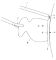
この状態で、体外においてシャフト2の他端を操作して、糸拡張部3を心尖側から左心耳Xに近接させ、糸拡張部3の保持部6の内側に左心耳Xを挿入していく。このとき、図4および図5に示されるように、別途挿入した把持鉗子12によって左心耳Xの先端を引っ張りながら、シャフト2を押して糸拡張部3を押し込んでいくことにより、糸拡張部3を左心耳Xの根元付近に配置することができる。 Thereby, the loop-shapedpart 5 a of the ligature 5 held in the accommodation hole 10 of the holding part 6 is held in a state of being expanded to the same size as the holding part 6.
In this state, the other end of theshaft 2 is operated outside the body to bring the thread expansion portion 3 close to the left atrial appendage X from the apex side, and the left atrial appendage X is inserted inside the holding portion 6 of the thread expansion portion 3. . At this time, as shown in FIG. 4 and FIG. 5, while pulling the distal end of the left atrial appendage X with the gripping forceps 12 inserted separately, the shaft 2 is pushed to push the thread expanding portion 3, thereby It can be placed near the base of the left atrial appendage X.
この状態で、体外においてシャフト2の他端を操作して、糸拡張部3を心尖側から左心耳Xに近接させ、糸拡張部3の保持部6の内側に左心耳Xを挿入していく。このとき、図4および図5に示されるように、別途挿入した把持鉗子12によって左心耳Xの先端を引っ張りながら、シャフト2を押して糸拡張部3を押し込んでいくことにより、糸拡張部3を左心耳Xの根元付近に配置することができる。 Thereby, the loop-shaped
In this state, the other end of the
このように、本実施形態に係る結紮デバイス1によれば、糸拡張部3が、相互に交差する第1面Aと第2面Cとによりシャフト2とは逆方向に凹となるように湾曲する展開面に沿って延びているので、図5に示されるように、心臓表面の凸曲面形状に沿うように配置され、左心耳Xの根元により近い位置に結紮糸5のループ状部5aを配置することができる。その結果、糸拡張部3から開放された結紮糸5のループ状部5aによって、左心耳Xの根元を結紮することができる。その結果、左心耳が特に曲率の小さい凸面形状の心臓表面に存在している場合に最適な結紮デバイスを提供することができる。
Thus, according to the ligating device 1 according to the present embodiment, the yarn expanding portion 3 is curved so as to be recessed in the opposite direction to the shaft 2 due to the first surface A and the second surface C intersecting each other. As shown in FIG. 5, the loop-shaped portion 5a of the ligature 5 is disposed at a position closer to the root of the left atrial appendage X, as shown in FIG. Can be arranged. As a result, the root of the left atrial appendage X can be ligated by the loop-shaped portion 5a of the ligature 5 released from the yarn expansion portion 3. As a result, an optimal ligation device can be provided when the left atrial appendage is present on a convex heart surface having a particularly small curvature.
また、本実施形態によれば、糸拡張部3が、その長手軸に平行な軸線回りにシャフト2に対して角度θ2をなして傾斜しているので、図3に示されるようにシャフト2の基端側から見て、糸拡張部3を構成している一方の平行部8が手前側に、他方の平行部8が奥側に配置される。これにより、心尖側から心臓の表面に沿って配置されるシャフト2の先端の糸拡張部3の、特に奥側の平行部8を左心耳Xと心臓表面との境界に近づけることができ、左心耳Xの根元により近い位置に結紮糸5のループ状部5aを配置することができる。
In addition, according to the present embodiment, the yarn expansion portion 3 is inclined at an angle θ2 with respect to the shaft 2 around an axis parallel to the longitudinal axis thereof, so that the shaft 2 has a shape as shown in FIG. When viewed from the base end side, one parallel portion 8 constituting the yarn expansion portion 3 is disposed on the near side, and the other parallel portion 8 is disposed on the back side. Thereby, the parallel part 8 of the thread expansion part 3 at the tip of the shaft 2 arranged along the surface of the heart from the apex side can be brought close to the boundary between the left atrial appendage X and the heart surface. The loop-shaped portion 5a of the ligature 5 can be disposed at a position closer to the root of the atrial appendage X.
また、本実施形態によれば、略U字状の保持部6が、ほぼ全周にわたってループ状部5aを収容孔10内に収容しているので、左心耳Xを保持部6内に挿入する操作中にループ状部5aが左心耳Xに引っかかることがなく、作業を容易にすることができる。
Moreover, according to this embodiment, since the substantially U-shaped holding part 6 has accommodated the loop-shaped part 5a in the accommodation hole 10 over the entire circumference, the left atrial appendage X is inserted into the holding part 6. The loop portion 5a is not caught by the left atrial appendage X during operation, and the operation can be facilitated.
また、一定の間隔をあけて略平行に配置される2本の平行部8によって、糸拡張部3が略長円状または略長方形状に形成されているので、間に挿入される左心耳Xを厚さ方向に挟んで近接する位置に配置することができる。さらに、糸拡張部3の長手方向の内径寸法が35mmから50mm程度に設定されているので、一般的な左心耳Xを容易に挿入できるとともに、挿入した左心耳Xの幅方向の表面から大きく離れない位置に先端部9のループ状部分を配置することができる。
Further, since the thread expansion portion 3 is formed in a substantially oval shape or a substantially rectangular shape by the two parallel portions 8 arranged substantially in parallel with a predetermined interval, the left atrial appendage X inserted between them Can be arranged at positions adjacent to each other in the thickness direction. Furthermore, since the inner diameter dimension of the longitudinal direction of the thread expansion portion 3 is set to about 35 mm to 50 mm, a general left atrial appendage X can be easily inserted, and it is greatly separated from the surface in the width direction of the inserted left atrial appendage X. The loop-shaped part of the front-end | tip part 9 can be arrange | positioned in the position which is not.
その結果、牽引されることにより、スリット11を介して収容孔10から引き出されたループ状部5aは、引き出されると左心耳の結紮を行うことができる。
As a result, when pulled, the loop-shaped portion 5a pulled out from the accommodation hole 10 through the slit 11 can perform ligation of the left atrial appendage.
なお、本実施形態においては、糸拡張部3が、相互に交差する第1面Aと第2面Cとを含む展開面に沿って屈曲するように湾曲する形態を有する場合について例示したが、これに代えて、図6に示されるように、連続的に湾曲する曲面からなる展開面に沿って湾曲する形態を有していてもよい。
In addition, in this embodiment, although illustrated about the case where the thread expansion part 3 has a form which curves so that it may bend along the expansion | deployment surface containing the 1st surface A and the 2nd surface C which mutually cross | intersect, Instead of this, as shown in FIG. 6, it may have a form that curves along a development surface composed of a curved surface that curves continuously.
また、本実施形態においては、糸拡張部3がその長手軸に平行な軸線回りにシャフト2に対して傾斜していることとしたが、これに代えて、シャフト2の長手軸Bと糸拡張部3の長手軸とを含む平面に直交していてもよい。
In the present embodiment, the thread expansion portion 3 is inclined with respect to the shaft 2 around the axis parallel to the longitudinal axis. Instead, the longitudinal axis B of the shaft 2 and the thread expansion It may be orthogonal to a plane including the longitudinal axis of the portion 3.
また、本実施形態においては、糸拡張部3が長円形状を有する場合を例示したが、これに代えて、図7に示されるように、略円形に形成されていてもよい。このようにすることで、左心耳Xに対するシャフト2の配置を任意に選択することができるという利点がある。
Further, in the present embodiment, the case where the yarn extending portion 3 has an oval shape is illustrated, but instead, it may be formed in a substantially circular shape as shown in FIG. By doing in this way, there exists an advantage that arrangement | positioning of the shaft 2 with respect to the left atrial appendage X can be selected arbitrarily.
すなわち、特に、図2に示されるように、2本の平行部8の位置関係がシャフト2の長手方向に異なる位置に配置されている場合には、手前側に配置されている平行部8が心臓と左心耳Xとの間に配置されるようにシャフト2を配置する必要がある。糸拡張部3を略円形とすることにより、図8に示されるように、湾曲している先端部9を心臓と左心耳Xとの間に挿入し、シャフト2を押し込む力によってフレーム部7を湾曲させて基端部を奥側に配置することで、左心耳Xの根元により近い位置に先端部9のループ状部分を配置することができる。
That is, in particular, as shown in FIG. 2, when the positional relationship between the two parallel portions 8 is arranged at different positions in the longitudinal direction of the shaft 2, the parallel portions 8 arranged on the near side are arranged. It is necessary to arrange the shaft 2 so as to be arranged between the heart and the left atrial appendage X. By making the thread expansion portion 3 substantially circular, as shown in FIG. 8, the curved tip portion 9 is inserted between the heart and the left atrial appendage X, and the frame portion 7 is pushed by the force of pushing the shaft 2. By curving and disposing the proximal end portion on the back side, the loop-shaped portion of the distal end portion 9 can be disposed at a position closer to the root of the left atrial appendage X.
1 結紮デバイス
2 シャフト
3 糸拡張部
5 結紮糸
5a ループ状部(ループ状部分)
7 フレーム部(基端部)
8 平行部
9 先端部
A 平面(第1面)
B 長手軸
C 平面(第2面)
DESCRIPTION OFSYMBOLS 1 Ligation device 2 Shaft 3 Yarn expansion part 5 Ligation thread 5a Loop-shaped part (loop-shaped part)
7 Frame (base end)
8Parallel part 9 Tip part A Plane (first surface)
B Longitudinal axis C Plane (second surface)
2 シャフト
3 糸拡張部
5 結紮糸
5a ループ状部(ループ状部分)
7 フレーム部(基端部)
8 平行部
9 先端部
A 平面(第1面)
B 長手軸
C 平面(第2面)
DESCRIPTION OF
7 Frame (base end)
8
B Longitudinal axis C Plane (second surface)
Claims (7)
- 緊縮可能なループ状部分を備える結紮糸と、
細長いシャフトと、
該シャフトの先端に固定され、前記結紮糸の前記ループ状部分を広げた状態で、解放可能に保持する糸拡張部とを備え、
該糸拡張部が、自由状態において、前記シャフトの長手軸に交差する展開面に沿って延びるとともに、該展開面が、前記シャフトとは逆方向に凹となるように湾曲している結紮デバイス。 A ligature comprising a loopable portion that can be tightened;
An elongated shaft;
A thread expansion portion that is fixed to the tip of the shaft and holds the looped portion of the ligature thread in a releasable state; and
A ligation device in which the yarn expanding portion extends in a free state along a deployment surface that intersects the longitudinal axis of the shaft, and the deployment surface is curved so as to be concave in a direction opposite to the shaft. - 前記糸拡張部が、前記シャフトに接続する基端部と、前記シャフトから離れた位置に配置される先端部とを備え、
前記展開面が、前記基端部を沿わせる略平面からなる第1面と、該第1面に交差し前記先端部を沿わせる略平面からなる第2面とを備える請求項1に記載の結紮デバイス。 The yarn extending portion includes a proximal end portion connected to the shaft and a distal end portion disposed at a position away from the shaft;
The said expansion | deployment surface is equipped with the 1st surface which consists of a substantially plane which follows the said base end part, and the 2nd surface which consists of a substantially plane which cross | intersects this 1st surface and follows the said front-end | tip part. Ligation device. - 前記糸拡張部が、前記結紮糸の前記ループ状部分の最大内径が約35mmから50mmとなるように広げた状態に保持する請求項1または請求項2に記載の結紮デバイス。 The ligating device according to claim 1 or 2, wherein the yarn expanding portion holds the loop-shaped portion of the ligature yarn in an expanded state so that a maximum inner diameter is about 35 mm to 50 mm.
- 前記糸拡張部が、該糸拡張部の基端と先端との間に、略一定間隔をあけた略平行な平行部を備える請求項1から請求項3のいずれかに記載の結紮デバイス。 The ligation device according to any one of claims 1 to 3, wherein the yarn extending portion includes a substantially parallel parallel portion having a substantially constant interval between a base end and a distal end of the yarn expanding portion.
- 前記平行部が長手方向を有し、前記展開面の長手方向に湾曲している請求項4に記載の結紮デバイス。 The ligation device according to claim 4, wherein the parallel portion has a longitudinal direction and is curved in the longitudinal direction of the development surface.
- 前記糸拡張部が、略環状に形成されている請求項1から請求項5のいずれかに記載の結紮デバイス。 The ligating device according to any one of claims 1 to 5, wherein the yarn extending portion is formed in a substantially annular shape.
- 前記糸拡張部が、該糸拡張部の基端から先端に延びる軸線回りに前記シャフトの前記長手軸に対して傾斜している請求項1から請求項6のいずれかに記載の結紮デバイス。
The ligation device according to any one of claims 1 to 6, wherein the yarn extending portion is inclined with respect to the longitudinal axis of the shaft around an axis extending from a proximal end of the yarn extending portion to a distal end.
Priority Applications (2)
| Application Number | Priority Date | Filing Date | Title |
|---|---|---|---|
| PCT/JP2016/062722 WO2017183174A1 (en) | 2016-04-22 | 2016-04-22 | Ligation device |
| JP2018512734A JPWO2017183174A1 (en) | 2016-04-22 | 2016-04-22 | Ligation device |
Applications Claiming Priority (1)
| Application Number | Priority Date | Filing Date | Title |
|---|---|---|---|
| PCT/JP2016/062722 WO2017183174A1 (en) | 2016-04-22 | 2016-04-22 | Ligation device |
Publications (1)
| Publication Number | Publication Date |
|---|---|
| WO2017183174A1 true WO2017183174A1 (en) | 2017-10-26 |
Family
ID=60116841
Family Applications (1)
| Application Number | Title | Priority Date | Filing Date |
|---|---|---|---|
| PCT/JP2016/062722 WO2017183174A1 (en) | 2016-04-22 | 2016-04-22 | Ligation device |
Country Status (2)
| Country | Link |
|---|---|
| JP (1) | JPWO2017183174A1 (en) |
| WO (1) | WO2017183174A1 (en) |
Citations (2)
| Publication number | Priority date | Publication date | Assignee | Title |
|---|---|---|---|---|
| JP2009501570A (en) * | 2005-07-14 | 2009-01-22 | アイディエックス・メディカル・エルティーディー | Apparatus and method for occluding a hollow anatomical structure |
| JP2015195837A (en) * | 2014-03-31 | 2015-11-09 | オリンパス株式会社 | Treatment instrument for atrial appendage ligation, and atrial appendage ligation system |
-
2016
- 2016-04-22 JP JP2018512734A patent/JPWO2017183174A1/en active Pending
- 2016-04-22 WO PCT/JP2016/062722 patent/WO2017183174A1/en active Application Filing
Patent Citations (2)
| Publication number | Priority date | Publication date | Assignee | Title |
|---|---|---|---|---|
| JP2009501570A (en) * | 2005-07-14 | 2009-01-22 | アイディエックス・メディカル・エルティーディー | Apparatus and method for occluding a hollow anatomical structure |
| JP2015195837A (en) * | 2014-03-31 | 2015-11-09 | オリンパス株式会社 | Treatment instrument for atrial appendage ligation, and atrial appendage ligation system |
Also Published As
| Publication number | Publication date |
|---|---|
| JPWO2017183174A1 (en) | 2019-02-21 |
Similar Documents
| Publication | Publication Date | Title |
|---|---|---|
| JP5386010B2 (en) | Suture anchor | |
| KR101975732B1 (en) | Clip cartridge | |
| JP3776529B2 (en) | Clip device | |
| EP2157914B1 (en) | Tissue aperture securing and sealing apparatuses | |
| JP6396667B2 (en) | Auricular ligation system | |
| JP6332998B2 (en) | Atrial ligation instrument | |
| JP6014963B2 (en) | Medical suture package | |
| JP2005334649A (en) | Apparatus and method for occluding hollow anatomical structure | |
| US20130218173A1 (en) | Surgical instrument for manipulating and passing suture | |
| JP2007521901A (en) | Tubular prosthesis | |
| CN109310441A (en) | Polymer ligation clip | |
| JP5869098B2 (en) | Suture anchor | |
| JP6149779B2 (en) | Endoscopic clip with spring | |
| JP2013509275A (en) | Iris retractor | |
| JP2020529259A (en) | Reinforced mechanical hemostatic clip | |
| JP2007097664A (en) | Clip for endoscope | |
| JP5784856B2 (en) | Suture device | |
| US20220401112A1 (en) | Medical instrument | |
| US20190142403A1 (en) | Tissue closure device | |
| JP6249824B2 (en) | Atrial ligation instrument and atrial ligation system | |
| WO2017183174A1 (en) | Ligation device | |
| JPWO2017183161A1 (en) | Ligation device | |
| JP2022522472A (en) | Deployment of hemostatic clips | |
| US20210196259A1 (en) | Method and apparatus for supporting a u-shaped portion of an elongate flexible element relative to a human body tissue | |
| JP6223642B2 (en) | Suture and suture system |
Legal Events
| Date | Code | Title | Description |
|---|---|---|---|
| ENP | Entry into the national phase |
Ref document number: 2018512734 Country of ref document: JP Kind code of ref document: A |
|
| NENP | Non-entry into the national phase |
Ref country code: DE |
|
| 121 | Ep: the epo has been informed by wipo that ep was designated in this application |
Ref document number: 16899446 Country of ref document: EP Kind code of ref document: A1 |
|
| 122 | Ep: pct application non-entry in european phase |
Ref document number: 16899446 Country of ref document: EP Kind code of ref document: A1 |