WO2017179641A1 - レーザ加工機及びレーザ加工方法 - Google Patents
レーザ加工機及びレーザ加工方法 Download PDFInfo
- Publication number
- WO2017179641A1 WO2017179641A1 PCT/JP2017/015065 JP2017015065W WO2017179641A1 WO 2017179641 A1 WO2017179641 A1 WO 2017179641A1 JP 2017015065 W JP2017015065 W JP 2017015065W WO 2017179641 A1 WO2017179641 A1 WO 2017179641A1
- Authority
- WO
- WIPO (PCT)
- Prior art keywords
- laser
- plate
- plate material
- assist gas
- limit value
- Prior art date
- Legal status (The legal status is an assumption and is not a legal conclusion. Google has not performed a legal analysis and makes no representation as to the accuracy of the status listed.)
- Ceased
Links
Images




Classifications
-
- B—PERFORMING OPERATIONS; TRANSPORTING
- B23—MACHINE TOOLS; METAL-WORKING NOT OTHERWISE PROVIDED FOR
- B23K—SOLDERING OR UNSOLDERING; WELDING; CLADDING OR PLATING BY SOLDERING OR WELDING; CUTTING BY APPLYING HEAT LOCALLY, e.g. FLAME CUTTING; WORKING BY LASER BEAM
- B23K26/00—Working by laser beam, e.g. welding, cutting or boring
-
- B—PERFORMING OPERATIONS; TRANSPORTING
- B23—MACHINE TOOLS; METAL-WORKING NOT OTHERWISE PROVIDED FOR
- B23K—SOLDERING OR UNSOLDERING; WELDING; CLADDING OR PLATING BY SOLDERING OR WELDING; CUTTING BY APPLYING HEAT LOCALLY, e.g. FLAME CUTTING; WORKING BY LASER BEAM
- B23K26/00—Working by laser beam, e.g. welding, cutting or boring
- B23K26/14—Working by laser beam, e.g. welding, cutting or boring using a fluid stream, e.g. a jet of gas, in conjunction with the laser beam; Nozzles therefor
-
- B—PERFORMING OPERATIONS; TRANSPORTING
- B23—MACHINE TOOLS; METAL-WORKING NOT OTHERWISE PROVIDED FOR
- B23K—SOLDERING OR UNSOLDERING; WELDING; CLADDING OR PLATING BY SOLDERING OR WELDING; CUTTING BY APPLYING HEAT LOCALLY, e.g. FLAME CUTTING; WORKING BY LASER BEAM
- B23K26/00—Working by laser beam, e.g. welding, cutting or boring
- B23K26/14—Working by laser beam, e.g. welding, cutting or boring using a fluid stream, e.g. a jet of gas, in conjunction with the laser beam; Nozzles therefor
- B23K26/142—Working by laser beam, e.g. welding, cutting or boring using a fluid stream, e.g. a jet of gas, in conjunction with the laser beam; Nozzles therefor for the removal of by-products
-
- B—PERFORMING OPERATIONS; TRANSPORTING
- B23—MACHINE TOOLS; METAL-WORKING NOT OTHERWISE PROVIDED FOR
- B23K—SOLDERING OR UNSOLDERING; WELDING; CLADDING OR PLATING BY SOLDERING OR WELDING; CUTTING BY APPLYING HEAT LOCALLY, e.g. FLAME CUTTING; WORKING BY LASER BEAM
- B23K26/00—Working by laser beam, e.g. welding, cutting or boring
- B23K26/36—Removing material
- B23K26/38—Removing material by boring or cutting
-
- B—PERFORMING OPERATIONS; TRANSPORTING
- B23—MACHINE TOOLS; METAL-WORKING NOT OTHERWISE PROVIDED FOR
- B23K—SOLDERING OR UNSOLDERING; WELDING; CLADDING OR PLATING BY SOLDERING OR WELDING; CUTTING BY APPLYING HEAT LOCALLY, e.g. FLAME CUTTING; WORKING BY LASER BEAM
- B23K2101/00—Articles made by soldering, welding or cutting
- B23K2101/18—Sheet panels
-
- B—PERFORMING OPERATIONS; TRANSPORTING
- B23—MACHINE TOOLS; METAL-WORKING NOT OTHERWISE PROVIDED FOR
- B23K—SOLDERING OR UNSOLDERING; WELDING; CLADDING OR PLATING BY SOLDERING OR WELDING; CUTTING BY APPLYING HEAT LOCALLY, e.g. FLAME CUTTING; WORKING BY LASER BEAM
- B23K2103/00—Materials to be soldered, welded or cut
- B23K2103/02—Iron or ferrous alloys
- B23K2103/04—Steel or steel alloys
-
- B—PERFORMING OPERATIONS; TRANSPORTING
- B23—MACHINE TOOLS; METAL-WORKING NOT OTHERWISE PROVIDED FOR
- B23K—SOLDERING OR UNSOLDERING; WELDING; CLADDING OR PLATING BY SOLDERING OR WELDING; CUTTING BY APPLYING HEAT LOCALLY, e.g. FLAME CUTTING; WORKING BY LASER BEAM
- B23K2103/00—Materials to be soldered, welded or cut
- B23K2103/08—Non-ferrous metals or alloys
- B23K2103/10—Aluminium or alloys thereof
Definitions
- the present disclosure relates to a laser processing machine and a laser processing method for cutting an aluminum plate by irradiating a laser beam.
- Patent Document 1 describes a laser processing machine that cuts an aluminum workpiece using a mixed gas of nitrogen gas and oxygen gas.
- the laser oscillator there are various oscillators such as a CO 2 laser oscillator, a fiber laser oscillator, and a direct diode laser oscillator (DDL oscillator).
- a CO 2 laser oscillator a CO 2 laser oscillator
- a fiber laser oscillator a fiber laser oscillator
- DDL oscillator a direct diode laser oscillator
- the CO 2 laser oscillator is large in size and high in cost.
- the fiber laser oscillator and the DDL oscillator can reduce the size of the apparatus and have a low running cost.
- the CO 2 laser oscillator has a wavelength of emitted laser light of about 10 ⁇ m
- the fiber laser oscillator or the DDL oscillator has a wavelength of emitted laser light of about 1 ⁇ m. Accordingly, the laser light emitted from the fiber laser oscillator or the DDL oscillator has a small beam waist and a high power density, and thus is suitable for processing a thin plate material at high speed.
- a laser processing machine using a CO 2 laser oscillator can perform processing with less dross without excessively oxidizing the cut surface by mixing a small amount of oxygen gas with nitrogen gas.
- Embodiments are intended to provide a laser beam machine and a laser beam machining method capable of sufficiently cutting an edge part and generating dross and cutting an aluminum plate with good cutting quality.
- a laser oscillator that emits laser light having a wavelength of 1 ⁇ m band, and a plate material mainly composed of aluminum irradiated with the laser light emitted from the laser oscillator, the plate material is A laser processing unit having a processing head for cutting, and a mixed gas supply unit configured to adjust an oxygen concentration and a gas pressure of a mixed gas containing oxygen and to supply the processing head, the laser processing unit including the laser beam With the beam waist adjusted to be positioned closer to the processing head than the plate material, the plate material is irradiated with the laser light emitted from the nozzle provided at the tip of the processing head, The mixed gas is jetted onto the plate as an assist gas, and the plate is a pure aluminum material having a 1000 series material symbol, and the plate thickness of the plate is x When m, the mixed gas supply unit multiplies the oxygen concentration in the assist gas by the volume flow rate of the assist gas, the plate thickness of the plate material, and the assist gas pressure, and divides by the opening
- the mixed gas is adjusted so that the index calculated by multiplying the value by 1000 is set within the range between the upper limit value ya obtained by Expression (5) and the lower limit value yc obtained by Expression (6).
- a laser beam machine characterized by this is provided.
- ya 0.0043e 0.6424x
- yc 0.0034e 0.3896x (6)
- a laser oscillator that emits laser light having a wavelength of 1 ⁇ m band, and the plate material mainly composed of aluminum is irradiated with the laser light emitted from the laser oscillator
- the plate material is A laser processing unit having a processing head for cutting, and a mixed gas supply unit configured to adjust an oxygen concentration and a gas pressure of a mixed gas containing oxygen and to supply the processing head, the laser processing unit including the laser beam With the beam waist adjusted to be positioned closer to the processing head than the plate material, the plate material is irradiated with the laser light emitted from the nozzle provided at the tip of the processing head, A gas mixture is jetted onto the plate as an assist gas, and the plate is an aluminum magnesium alloy having a material symbol of 5000 series, When the thickness is xmm, the mixed gas supply unit multiplies the oxygen concentration in the assist gas by the volume flow rate of the assist gas, the plate thickness of the plate member, and the assist gas pressure, and the opening area of the nozzle
- the mixed gas supply unit multiplies
- a plate material which is a pure aluminum material having a 1000 series material symbol, is used as a plate material to be processed, and the wavelength is in a 1 ⁇ m band from a nozzle provided at the tip of the processing head.
- the laser beam is emitted and the plate is irradiated with the laser beam in a state where the beam waist of the laser beam is adjusted to be located on the nozzle side, and the plate thickness of the plate is xmm
- An index calculated by multiplying the oxygen concentration of the gas by the volume flow rate of the assist gas, the plate thickness of the plate material, and the assist gas pressure, and multiplying by 1000 the value obtained by dividing by the opening area of the nozzle is expressed by the equation (5).
- a plate material made of an aluminum magnesium alloy having a material symbol of 5000 series is used as a plate material to be processed, and a laser whose wavelength is in a 1 ⁇ m band from a nozzle provided at the tip of the processing head.
- the assist gas is adjusted so as to be set within the range between the upper limit value yd obtained by the equation (6) and the lower limit value yf obtained by the equation (6).
- the laser processing machine and the laser processing method of the embodiment it is possible to cut the aluminum plate material with a good cutting quality by sufficiently suppressing the occurrence of chipping and dross at the edge portion.
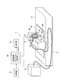
- FIG. 1 is a perspective view showing an example of the overall configuration of a laser beam machine according to an embodiment.
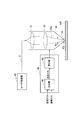
- FIG. 2 is a diagram illustrating a schematic configuration example of a mixed gas supply unit of a laser beam machine according to an embodiment.
- FIG. 3 is a diagram showing a schematic configuration when the laser oscillator in FIG. 1 is configured by a fiber laser oscillator.
- FIG. 4 is a diagram showing a schematic configuration when the laser oscillator in FIG. 1 is configured by a direct diode laser oscillator.
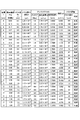
- FIG. 5 is a diagram showing the relationship between the laser processing conditions and the processing quality when the aluminum plate material AW is a pure aluminum-based material A1050.
- FIG. 1 is a perspective view showing an example of the overall configuration of a laser beam machine according to an embodiment.
- FIG. 2 is a diagram illustrating a schematic configuration example of a mixed gas supply unit of a laser beam machine according to an embodiment.
- FIG. 3 is a diagram showing a schematic configuration when the laser oscill
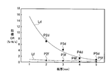
- FIG. 6 is a diagram showing the relationship between the plate thickness and the index GR when the material of the aluminum plate AW is A1050 of pure aluminum material.
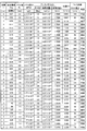
- FIG. 7A is a diagram showing the relationship between the laser processing conditions and the processing quality when the aluminum plate material AW is an aluminum magnesium alloy A5052.
- FIG. 7B is a diagram showing a relationship between laser processing conditions and processing quality when the aluminum plate material AW is A5052 of aluminum magnesium alloy.
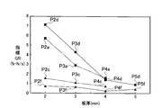
- FIG. 8 is a diagram showing the relationship between the plate thickness and the index GR when the aluminum plate material AW is made of aluminum magnesium alloy A5052.
- FIG. 9 is a diagram showing the relationship between the plate thickness and the index GR when the aluminum plate material AW is made of pure aluminum-based material A1050 and aluminum magnesium alloy A5052.
- a laser beam machine and a laser beam machining method according to an embodiment will be described with reference to the accompanying drawings.
- the wavelength of laser light emitted from the fiber laser oscillator is generally 1060 nm to 1080 nm, and the wavelength of laser light emitted from the DDL oscillator is generally 910 nm to 950 nm.
- a wavelength of 900 nm to 1100 nm is referred to as a 1 ⁇ m band.
- the laser beam machine 1 cuts the aluminum plate material AW by irradiating a laser beam 10a to a plate material AW mainly composed of aluminum (hereinafter referred to as an aluminum plate material AW).
- the laser processing machine 1 includes a laser oscillator 10, a laser processing unit 20, a process fiber 2, a control device 50, an operation unit 51, and a display unit 52.
- the control device 50 includes a holding unit 501.
- the holding unit 501 may be provided outside the control device 50.
- the control device 50 can be configured by an NC device.
- Control device 50 controls laser oscillator 10 and laser processing unit 20.
- the operator can set various parameters when the aluminum plate AW is processed by operating the operation unit 51.
- the control device 50 controls the laser processing machine 1 to process the aluminum plate material AW based on automatically set parameters or manually set parameters by the operation unit 51.
- the control device 50 controls the display unit 52 to display various types of information.
- the laser oscillator 10 generates and emits a laser beam 10a having a wavelength of 1 ⁇ m.
- the laser oscillator 10 is a fiber laser oscillator or a DDL oscillator. However, as long as it is a laser oscillator that emits laser light 10a having a wavelength of 1 ⁇ m, a fiber laser oscillator or a DDL oscillator may be used.
- the process fiber 2 has an input end connected to the laser oscillator 10 and an output end connected to the laser processing unit 20.
- the process fiber 2 is mounted along X-axis and Y-axis cable ducts (not shown) arranged in the laser processing unit 20.
- the process fiber 2 transmits the laser beam 10 a emitted from the laser oscillator 10 to the laser processing unit 20.
- the laser processing unit 20 includes a processing table 21 on which an aluminum plate AW is placed, a portal-shaped X-axis carriage 22 that is movable on the processing table 21 in the X-axis direction (left-right direction in FIG. 1), and an X-axis carriage 22 And a Y-axis carriage 23 that is movable in the Y-axis direction perpendicular to the X-axis (the front-rear direction in FIG. 1). Further, the laser processing unit 20 has a collimator unit 30 fixed to the Y-axis carriage 23.
- the collimator unit 30 collimates the laser light 10a transmitted from the output end of the process fiber 2 into a parallel light to make a substantially parallel light beam, and the laser light 10a converted into a substantially parallel light beam on the X axis and the Y axis. And a bend mirror 32 that reflects downward in the vertical Z-axis direction (vertical direction in FIG. 1). Further, the collimator unit 30 includes a focusing lens 33 (focusing lens) that focuses the laser light 10 a reflected by the bend mirror 32 to a high energy density, and a processing head 34.
- focusing lens 33 focusing lens
- the collimating lens 31, the bend mirror 32, the focusing lens 33, and the processing head 34 are fixed in the collimator unit 30 with the optical axis adjusted in advance.
- the focusing lens 33 is a single focus lens.
- the laser beam 10a focused by the focusing lens 33 is emitted from the nozzle 35 at the tip of the processing head 34 and is irradiated onto the aluminum plate AW at a single focal point.
- the laser beam 10a is irradiated to the aluminum plate AW at a single focal point in a state in which the beam waist is adjusted to be positioned slightly closer to the nozzle 35 (processing head 34) than the aluminum plate AW.
- the nozzle 35 is a single nozzle having one opening.
- the collimating lens 31 may be configured to move in the X-axis direction.
- the collimator unit 30 is fixed to a Y-axis carriage 23 movable in the Y-axis direction, and the Y-axis carriage 23 is provided on an X-axis carriage 22 movable in the X-axis direction. Therefore, the laser processing unit 20 can move the position where the laser beam 10a emitted from the processing head 34 is irradiated to the aluminum plate material AW in the X-axis direction and the Y-axis direction.
- the laser processing machine 1 includes a mixed gas supply unit 40.
- the mixed gas supply unit 40 temporarily stores and pressurizes a mixer (oxygen concentration regulator) 41 for mixing nitrogen gas and oxygen gas, and a mixed gas of nitrogen gas and oxygen gas, that is, a mixed gas containing oxygen, And a booster 42 for adjusting the gas pressure.
- a mixer oxygen concentration regulator
- Nitrogen gas may be supplied to the mixer 41 from a liquid nitrogen gas cylinder, or nitrogen-rich gas purified by a nitrogen separation membrane composed of a hollow fiber capable of separating nitrogen from air may be supplied. Good. Further, oxygen gas may be supplied to the mixer 41 from an oxygen gas cylinder, or oxygen-rich gas purified by an oxygen separation membrane composed of a hollow fiber capable of separating oxygen from air is supplied. Also good.
- the mixer 41 mixes nitrogen gas and oxygen gas, and adjusts the oxygen concentration (volume%) of the mixed gas.
- the mixer 41 is a mass flow controller that automatically controls the flow rate of the mixed gas via a valve that equalizes the pressure of nitrogen gas or oxygen gas.
- the mass flow may be manually adjusted from the measurement result of a mass flow meter that simply performs sensing.
- the air has about 21% (volume%) oxygen and about 78% (volume%) nitrogen. Therefore, clean air from which fine particles have been removed and nitrogen gas may be mixed by the mixer 41 to adjust the oxygen concentration (volume%) of the mixed gas.
- the booster 42 supplies the pressure-adjusted mixed gas into the processing head 34.
- the mixed gas supplied into the processing head 34 is ejected from the nozzle 35 at the tip of the processing head 34 to the aluminum plate AW as an assist gas AG. Dissolution of the aluminum plate material AW can be promoted by performing cutting with the laser beam 10a in combination with the assist gas AG. Thereby, the cutting speed of aluminum plate material AW and the surface roughness of a cut surface can be improved, and dross reduction can be aimed at.
- the laser processing machine 1 is a mixed gas of nitrogen gas and oxygen gas, and the aluminum plate material AW is irradiated with the laser beam 10a while the assist gas AG whose oxygen concentration is adjusted is jetted onto the aluminum plate material AW. Then, the aluminum plate material AW is cut.
- a robot type laser beam machine may be used.
- FIG. 3 shows a schematic configuration when the laser oscillator 10 is configured by a fiber laser oscillator 110.
- the fiber laser oscillator 110 includes a plurality of laser diodes 111, a pump combiner 112, two fiber Bragg gratings (FBGs) 113 and 115, a Yb-doped fiber 114, a feeding fiber 116, and a beam coupler 120.
- the beam coupler 120 includes lenses 121 and 122.
- the plurality of laser diodes 111 each emit laser light having a wavelength ⁇ .
- the excitation combiner 112 combines the laser beams emitted from the plurality of laser diodes 111 with a spatial beam.
- the laser beam that is spatially beam-coupled by the excitation combiner 112 is incident on the Yb-doped fiber 114 via the FBG 113.
- the Yb-doped fiber 114 is a fiber in which a rare earth Yb (ytterbium) element is added to the core.
- the laser light incident on the Yb-doped fiber 114 repeats reciprocation between the FBG 113 and the FBG 115.
- the FBG 115 emits laser light having a wavelength ⁇ ′ of approximately 1060 nm to 1080 nm, which is different from the wavelength ⁇ .
- the laser light emitted from the FBG 115 is incident on the beam coupler 120 via the feeding fiber 116.
- the laser light incident on the beam coupler 120 is incident on the process fiber 2 via the lenses 121 and 122.
- the laser light incident on the process fiber 2 corresponds to the laser light 10a shown in FIG.
- the process fiber 2 is composed of one optical fiber, and the laser light transmitted through the process fiber 2 is not combined with other laser light until the aluminum plate material AW is irradiated.
- FIG. 4 shows a schematic configuration when the laser oscillator 10 is configured by the DDL oscillator 210.
- the DDL oscillator 210 includes a plurality of laser diodes 2111 to 211n and an optical box 220.
- the laser diodes 2111 to 211n emit laser beams having different wavelengths ⁇ 1 to ⁇ n, respectively.
- the wavelengths ⁇ 1 to ⁇ n are 910 nm to 950 nm.
- the optical box 220 combines the laser beams emitted from the laser diodes 2111 to 211n with a spatial beam.
- the optical box 220 includes a collimating lens 221, a grating 222, and a focusing lens 223.
- the collimating lens 221 collimates the laser beam combined with the spatial beam.
- the grating 222 deflects the collimated laser beam by 90 degrees and makes it incident on the focusing lens 223.
- the focusing lens 223 focuses the laser light and makes it incident on the process fiber 2.
- the laser light incident on the process fiber 2 corresponds to the laser light 10a shown in FIG.
- the process fiber 2 is composed of one optical fiber, and the laser light transmitted through the process fiber 2 is not combined with other laser light until the aluminum plate material AW is irradiated.
- a laser processing method for cutting the aluminum plate material AW using the laser processing machine 1 will be described.
- Laser processing conditions differ depending on the material and thickness of the aluminum plate AW.
- a typical material of the aluminum plate material AW for example, there are a pure aluminum material having a material symbol of 1000 series and an aluminum magnesium alloy having a material symbol of 5000 series.
- A1050 (material symbol), which is a pure aluminum material (1000 series), is composed of 99.5% or more of an aluminum component and includes chemical components such as Si, Fe, Cu, Mn, Mg, Zn, and Ti. .
- Si is 0.25% or less
- Fe content is 0.4% or less.
- the other chemical components are each 0.05% or less.
- A5052 (material symbol) which is an aluminum magnesium alloy (5000 series) is a typical material having intermediate strength among aluminum alloys, and is the most frequently used alloy. A5052 contains chemical components such as Si, Fe, Cu, Mn, Mg, Cr and Zn in the main component aluminum. A5052 has a Mg content of 2.2% to 2.8%.
- the area to be cut increases.
- the amount of metal melted at the time of cutting is proportional to the plate thickness, and it is desirable to increase the opening diameter (nozzle diameter) Rn (see FIG. 2) of the nozzle 35 in order to blow away the melted metal within a certain time.
- the volume flow rate Q (m 3 / s) of the assist gas AG ejected from the nozzle 35 can be expressed by the formula (1).
- C is an outflow coefficient
- A is a flow path area, specifically, an opening area of the nozzle 35 (nozzle opening area) (m 2 )
- V is a volume flow velocity (m / s) of the assist gas AG. is there.
- the volume flow velocity V can be expressed by equation (2).
- an index GR gas parameter ratio (% ⁇ N / s) shown in Expression (3) is set as the laser processing condition.
- Oxg is the oxygen concentration (volume%) in the assist gas AG
- t is the plate thickness (mm) of the aluminum plate AW to be processed. That is, the index GR multiplies the oxygen concentration in the assist gas AG by the volume flow rate of the assist gas AG, the plate thickness of the aluminum plate AW, and the assist gas pressure, and multiplies the value divided by the opening area of the nozzle 35 by 1000. Is calculated by The plate thickness t and the nozzle opening area A are known in advance. Therefore, the index GR can be adjusted by the mixed gas supply unit 40. The reason why Oxg ⁇ (Q / A) ⁇ (t ⁇ P) is multiplied by 1000 is to adjust the digit of the numerical value of the index GR to make it easy to see.
- index GR can be expressed by Expression (4).
- the index GR corresponds to a value obtained by multiplying the product of the oxygen concentration per unit time and the force by 1000.
- the index GR is set as a laser processing condition, it is important that oxygen in the assist gas AG, which is a fluid, is continuously chemically reacted with the aluminum plate material AW, which is a workpiece. Therefore, the volume flow rate of oxygen is calculated by multiplying the oxygen concentration (volume%) in the assist gas AG by the volume flow velocity V (volume flow rate Q / nozzle opening area A) of the assist gas AG.
- the assist gas AG (specifically oxygen in the assist gas AG), which is a fluid having a mass, is accelerated to accelerate the aluminum plate AW. It is important to make it collide. Therefore, the assist gas pressure P is further multiplied by the calculated volume flow rate of oxygen.
- the force in Formula (4) is a force for applying the assist gas pressure P in a steady manner, and corresponds to the acceleration of the assist gas AG.
- Acceleration ⁇ mass flow rate force / time. That is, Oxg ⁇ force (N) / s in the equation (4) corresponds to the steady pressure per unit time of oxygen in the assist gas AG with respect to the aluminum plate material AW.
- FIGS. 5 to 9 laser processing conditions (cutting processing conditions) and processing quality evaluation results when the aluminum plate material AW is A1050 and A5052 will be described.
- the index GR in FIG. 5, FIG. 7A, and FIG. 7B is calculated by the above equation (3).
- the dross height in FIG. 7A and FIG. 7B is the height of the dross relative to the thickness of the aluminum plate material AW.
- the thickness of the aluminum plate AW including the dross portion after cutting is measured at a plurality of locations (for example, 9 locations), and the value obtained by subtracting the thickness of the aluminum plate AW before cutting from the average value Is shown.
- the dross height is 280 ⁇ m or less, when 5 mm, the dross height is 175 ⁇ m or less, when 4 mm, the dross height is 140 ⁇ m or less, and when the plate thickness is 3 mm, the dross height is 90 ⁇ m or less.
- the processing quality is determined to be good when the dross height satisfies the condition of 60 ⁇ m or less, and the other cases are determined to be defective.
- Example 1 A case where laser processing (cutting) of A1050 of a pure aluminum-based material (1000 series) is described as the aluminum plate AW will be described with reference to FIGS. 5 and 6.
- the index GR is in the range of 0.735% ⁇ N / s to 1.584% ⁇ N / s. By doing so, there is no defect of the edge part by cutting, and good cutting quality with less dross can be obtained.
- the oxygen concentration (volume%) at this time is in the range of 0.13% to 0.28%.
- the oxygen concentration (volume%) at this time is in the range of 0.19% to 0.34%.
- the index GR is set in the range of 1.145% ⁇ N / s to 15.456% ⁇ N / s, so that there is no loss of edge due to cutting. In addition, good cutting quality with low dross can be obtained.
- the oxygen concentration (volume%) at this time is in the range of 0.20% to 2.70%.
- the index GR is set to a range of 1.690% ⁇ N / s to 4.226% ⁇ N / s, so that the edge portion is lost due to cutting. And good cutting quality with low dross is obtained.
- the oxygen concentration (volume%) at this time is in the range of 0.70% to 1.75%.
- the ratio of chemical components other than aluminum is small. Therefore, if the plate thickness is large, the oxidation rate of oxygen staying on the cut surface and aluminum itself contributes to the cutting because the cutting speed is slow. On the other hand, when the plate thickness is thin, it is presumed that the oxidation reaction of aluminum itself contributes to cutting by supplying high-concentration oxygen considering that the molten alloy is blown away.
- the range of the index GR is widened if the plate thickness of the aluminum plate AW is thin. It is the result.
- a nozzle having a nozzle diameter Rn larger than that of the standard nozzle for example, equivalent to the thickness of the aluminum plate AW
- the assist gas pressure is adjusted so that the volume flow rate of the assist gas is the same as that of the standard nozzle.
- the nozzle diameter Rn is increased and the assist gas pressure is increased, the range of the index GR is increased.
- the index GR is 1.690 when the plate diameter is 2 mm to 3 mm and the nozzle diameter Rn is in the range of 67% to 100% of the plate thickness of the aluminum plate AW.
- the ratio in the range of% ⁇ N / s to 2.919% ⁇ N / s, it is possible to obtain a good cutting quality with less loss of edge portions due to cutting and less dross.
- cutting is performed by setting the index GR in the range of 0.735% ⁇ N / s to 1.584% ⁇ N / s. Therefore, it is possible to obtain a good cutting quality with no loss of the edge portion due to the low dross.
- FIG. 6 shows the relationship between the thickness of the aluminum plate AW of pure aluminum material (A1050) and the index GR.
- the exponent approximate curve La calculated by the measurement point P4a, the measurement point P3a, and the measurement point P2a is an upper limit line indicating the upper limit value of the index GR, and the exponent approximation curve calculated by the measurement point P4c, the measurement point P3c, and the measurement point P2c.
- Lc is a lower limit line indicating the lower limit value of the index GR.
- the upper limit value of the index GR is ya
- the lower limit value is yc
- the upper limit value ya and the lower limit value yc of the index GR are expressed by the formula ( 5) and the approximate expression shown in Expression (6).
- the index GR is an upper limit value ya expressed by the approximate expression shown by the expression (5) and an approximate expression expressed by the expression (5). If it is within the range of the lower limit value yc represented, the laser processing unit 20 is sufficient to suppress the occurrence of dross without causing the edge part to be lost due to the cutting of the aluminum plate material having the 1000 series material symbol. Thus, it can be cut with good cutting quality.
- Example 2 A case where laser processing (cutting) of A5052 of an aluminum magnesium alloy (5000 series) is described as the aluminum plate material AW will be described with reference to FIGS. 7A and 7B.
- the index GR is set to 1.874% ⁇ N / s, so that there is no loss of the edge portion due to cutting. In addition, it is possible to perform cutting with low dross and good cutting quality.
- the oxygen concentration (volume%) at this time is 0.10%.
- the index GR is in the range of 0.465% ⁇ N / s to 0.930% ⁇ N / s, so that there is no loss of edge due to cutting, and there is little dross. Cutting with good quality is possible.
- the oxygen concentration (volume%) at this time is in the range of 0.05% to 0.10%.
- the index GR is in the range of 0.283% ⁇ N / s to 1.414% ⁇ N / s, so that there is no loss of edge due to cutting, and there is little dross. Cutting with good quality is possible.
- the oxygen concentration (volume%) at this time is in the range of 0.05% to 0.25%.
- the plate thickness is 3 mm
- the index GR in the range of 0.687% ⁇ N / s to 4.293% ⁇ N / s, there is no loss of the edge due to cutting, In addition, good cutting quality with less dross can be obtained.
- the oxygen concentration (volume%) at this time is in the range of 0.08% to 0.50%.
- the index GR is set in the range of 0.744% ⁇ N / s to 7.155% ⁇ N / s so that the edge portion is lost due to cutting. And good cutting quality with low dross is obtained.
- the oxygen concentration (volume%) at this time is in the range of 0.13% to 1.25%.
- the edge portion is lost by cutting by setting the index GR in the range of 0.145% ⁇ N / s to 4.468% ⁇ N / s. And good cutting quality with low dross is obtained.
- the oxygen concentration (volume%) at this time is in the range of 0.06% to 2.17%.
- the heat of magnesium oxidation reaction contributes as the plate thickness increases.
- the thicker the plate thickness the greater the amount of blown away molten alloy.
- the thinner the plate thickness the shorter the contribution of the heat of oxidation reaction of magnesium, and the molten alloy can be easily blown away by the assist gas pressure.
- the range of the index GR is expanded if the thickness of the aluminum plate AW is thin. It is the result.
- a nozzle having a nozzle diameter Rn larger than that of the standard nozzle for example, equivalent to the thickness of the aluminum plate AW
- the assist gas pressure is adjusted so that the volume flow rate of the assist gas is the same as that of the standard nozzle.
- the index GR is 0.744%.
- the index GR is 1.874% ⁇ N / s at a thickness of 8 mm.
- FIG. 8 shows the relationship between the thickness of the aluminum plate AW of aluminum magnesium alloy (A5052) and the index GR.
- An exponential approximate curve Ld calculated from the measurement point P4d, the measurement point P3d, and the measurement point P2d is an upper limit line indicating the upper limit value of the index GR, and an exponential approximation curve calculated from the measurement point P4f, the measurement point P3f, and the measurement point P2f.
- Lf is a lower limit line indicating the lower limit value of the index GR.
- the upper limit value of the index GR is yd
- the lower limit value is yf
- the upper limit value yd and the lower limit value yf of the index GR are expressed by the formula (7 )
- the index GR is an upper limit value yd represented by the approximate expression represented by Expression (7) and an approximate expression represented by Expression (8). If it is within the range of the lower limit value yf represented, the laser processing unit 20 is sufficient to suppress the occurrence of dross without causing a loss of the edge part due to the cutting of the aluminum plate material having the material symbol of 5000 series. Thus, it can be cut with good cutting quality.
- FIG. 9 shows an upper limit value and a lower limit value of each index GR when a pure aluminum material (A1050) and an aluminum magnesium alloy (A5052) are used for the aluminum plate AW.
- the holding unit 501 holds Expressions (5) to (8).
- the index GR is an expression (5).
- the lower limit value yc obtained by the equation (6).
- the index GR is an expression (7).
- the lower limit value yf obtained by the equation (8).
- the expressions (5) and (6), the expressions (7) and (8) stored in the holding unit 501 are exponential approximate curve expressions, and the rate of change of the value of the index GR determined by the plate thickness is the index GR. Is an approximate expression proportional to the value of.
- the approximate expression can be solved by a differential equation from the rate of change of the value of the index GR. By calculating the constant used for the power of the base of the natural logarithm and the integral constant, it is possible to adjust a small amount of the approximate expression caused by the difference in steel material manufacturers. In the equations (5) to (8), 0.0043, 0.0034, 0.0041, and 0.0029 are integral constants.
- each index GR is changed according to the difference in steel material manufacturers and held in the holding unit 501, and the control device 50 calculates the constants and integral constants of the approximate expression and generates the expressions (5) to (8)
- the equations (5) to (8) may be held in the holding unit 501.
- control device 50 attempts to cut the aluminum plate material AW under the processing conditions set by the laser processing unit 20, whether or not the index GR is within the range between the upper limit values ya, yd and the lower limit values yc, yf.
- the determination result is controlled to be displayed on the display unit 52.
- the control device 50 displays different characters, symbols, or images on the display unit 52 depending on whether or not the index GR is within the range between the upper limit values ya, yd and the lower limit values yc, yf.
- the control device 50 displays a symbol ⁇ indicating good on the display unit 52 when the index GR is smaller than 95% of the upper limit values ya, yd or larger than 105% of the lower limit values yc, yf.
- the control device 50 displays a symbol ⁇ indicating caution on the display unit 52 when the index GR is 95% or more and 105% or less of the upper limit values ya and yd or 95% or more and 105% or less of the lower limit values yc and yf.
- the control device 50 displays a symbol x indicating impossibility on the display unit 52 when the index GR is greater than 105% of the upper limit values ya, yd or less than 95% of the lower limit values yc, yf.
- Symbols O, ⁇ , and X are examples of symbols, and the control device 50 may display characters on the display unit 52 such as “good”, “caution”, and “impossible”.
- the range to be noted is not limited to ⁇ 5% of the upper limit values ya, yd and the lower limit values yc, yf, and the control device 50 may be appropriately set to ⁇ 3% or ⁇ 7%.
- the control device 50 displays the determination result on the display unit 52, so that the operator can sufficiently suppress the occurrence of chipping and dross at the edge portion. It can be confirmed whether or not a satisfactory cutting quality can be obtained.
- the present invention can be used when an aluminum plate is cut with a laser beam.
Landscapes
- Engineering & Computer Science (AREA)
- Physics & Mathematics (AREA)
- Optics & Photonics (AREA)
- Plasma & Fusion (AREA)
- Mechanical Engineering (AREA)
- Laser Beam Processing (AREA)
Abstract
レーザ加工機(1)はレーザ発振器(10)とレーザ加工ユニット(20)と混合ガス供給部(40)を備える。レーザ発振器(10)は1μm帯のレーザ光(10a)を射出する。レーザ加工ユニット(20)は、アルミ板材(AW)にレーザ光(10a)を照射し、酸素を含むアシストガス(AG)を噴出する。混合ガス供給部(40)は、アルミ板材(AW)が1000系であり板厚をxmmとした場合、アシストガス(AG)中の酸素濃度に、アシストガス(AG)の体積流量とアルミ板材(AW)の板厚とアシストガス圧とを乗算し、ノズル(35)の開口面積で除算した値を1000倍することにより算出される指標が、ya=0.0043e0.6424xで表される上限値と、yc=0.0034e0.3896xで表される下限値との範囲内に設定されるようにアシストガス(AG)を調整する。
Description
本開示は、レーザ光を照射してアルミニウムの板材を切断するレーザ加工機及びレーザ加工方法に関する。
レーザ発振器から射出されたレーザ光を被加工物に照射することにより被加工物を切断加工するレーザ加工機が普及している。特許文献1には、窒素ガスと酸素ガスの混合ガスを用いてアルミニウム被加工物を切断加工するレーザ加工機が記載されている。
レーザ発振器として、CO2レーザ発振器、ファイバレーザ発振器、ダイレクトダイオードレーザ発振器(DDL発振器)等の各種の発振器がある。
CO2レーザ発振器は、装置が大型化し、高コストである。これに対して、ファイバレーザ発振器やDDL発振器は、装置を小型化することができ、低ランニングコストである。また、CO2レーザ発振器は、射出するレーザ光の波長が10μm程度であるのに対し、ファイバレーザ発振器またはDDL発振器は、射出するレーザ光の波長が1μm程度である。従って、ファイバレーザ発振器またはDDL発振器が射出するレーザ光は、ビームウエストが小さく、パワー密度が高いため、板厚が薄い板材を高速で加工するのに適している。
CO2レーザ発振器を用いるレーザ加工機は、窒素ガスに微量の酸素ガスを混合させることにより、切断面を過度に酸化させることなく、ドロスの少ない加工が可能である。
一方、ファイバレーザ発振器またはDDL発振器を用いるレーザ加工機は、被加工物としてアルミニウムを主成分とする板材を切断する場合、混合ガスによる酸化反応により切断面のエッジ部が欠損しやすい。また、窒素ガスを用いてアルミニウムの板材を切断する場合、ドロスが発生しやすい。エッジ部の欠損とドロスの発生の程度は板材の材質や板厚によっても異なる。
そのため、ファイバレーザ発振器またはDDL発振器を用いるレーザ加工機でアルミニウムの板材を切断する場合、特許文献1に記載されている混合ガス条件ではエッジ部の欠損及びドロスの発生を十分に抑制することができない場合がある。
例えば、特許文献1に記載されているような混合ガス条件では、材料記号が5000系のアルミニウムマグネシウム合金に対しては有効である。一方、材料記号が1000系の純アルミニウムに対してはエッジ部の欠損及びドロスの発生を十分に抑制することができず、良好な切断加工品質を得ることができない場合がある。また、特許文献1に記載されている混合ガス条件の範囲外の混合ガス条件でも良好な切断加工品質を得ることができる場合がある。
実施形態は、エッジ部の欠損及びドロスの発生を十分に抑制して、アルミニウムの板材を良好な切断加工品質で切断することができるレーザ加工機及びレーザ加工方法を提供することを目的とする。
実施形態の第1の態様によれば、波長が1μm帯であるレーザ光を射出するレーザ発振器と、前記レーザ発振器から射出されたレーザ光をアルミニウムを主成分とする板材に照射して前記板材を切断加工する加工ヘッドを有するレーザ加工ユニットと、酸素を含む混合ガスの酸素濃度及びガス圧を調整して前記加工ヘッドに供給する混合ガス供給部とを備え、前記レーザ加工ユニットは、前記レーザ光のビームウエストが前記板材よりも前記加工ヘッド側に位置するように調整された状態で、前記加工ヘッドの先端部に設けられているノズルから射出された前記レーザ光を前記板材に照射し、前記混合ガスをアシストガスとして前記板材に噴出し、前記板材が1000系の材料記号を有する純アルミニウム系材料であり、前記板材の板厚をxmmとしたとき、前記混合ガス供給部は、前記アシストガス中の酸素濃度に、前記アシストガスの体積流量と前記板材の板厚とアシストガス圧とを乗算し、前記ノズルの開口面積で除算した値を1000倍することにより算出される指標が、式(5)で得られる上限値yaと式(6)で得られる下限値ycとの範囲内に設定されるように前記混合ガスを調整することを特徴とするレーザ加工機が提供される。
ya=0.0043e0.6424x …(5)
yc=0.0034e0.3896x …(6)
ya=0.0043e0.6424x …(5)
yc=0.0034e0.3896x …(6)
実施形態の第2の態様によれば、波長が1μm帯であるレーザ光を射出するレーザ発振器と、前記レーザ発振器から射出されたレーザ光をアルミニウムを主成分とする板材に照射して前記板材を切断加工する加工ヘッドを有するレーザ加工ユニットと、酸素を含む混合ガスの酸素濃度及びガス圧を調整して前記加工ヘッドに供給する混合ガス供給部とを備え、前記レーザ加工ユニットは、前記レーザ光のビームウエストが前記板材よりも前記加工ヘッド側に位置するように調整された状態で、前記加工ヘッドの先端部に設けられているノズルから射出された前記レーザ光を前記板材に照射し、前記混合ガスをアシストガスとして前記板材に噴出し、前記板材が5000系の材料記号を有するアルミニウムマグネシウム合金であり、前記板材の板厚をxmmとしたとき、前記混合ガス供給部は、前記アシストガス中の酸素濃度に、前記アシストガスの体積流量と前記板材の板厚とアシストガス圧とを乗算し、前記ノズルの開口面積で除算した値を1000倍することにより算出される指標が、式(7)で得られる上限値ydと式(8)で得られる下限値yfとの範囲内に設定されるように前記混合ガスを調整することを特徴とするレーザ加工機が提供される。
yd=0.0041e0.7233x …(7)
yf=0.0029e0.23x …(8)
yd=0.0041e0.7233x …(7)
yf=0.0029e0.23x …(8)
実施形態の第3の態様によれば、1000系の材料記号を有する純アルミニウム系材料である板材を加工対象の板材とし、加工ヘッドの先端部に設けられたノズルから、波長が1μm帯であるレーザ光を射出し、前記レーザ光のビームウエストが前記ノズル側に位置するように調整された状態で前記レーザ光を前記板材に照射し、前記板材の板厚をxmmとしたとき、アシストガス中の酸素濃度に、前記アシストガスの体積流量と前記板材の板厚とアシストガス圧とを乗算し、前記ノズルの開口面積で除算した値を1000倍することにより算出される指標が、式(5)で得られる上限値yaと式(6)で得られる下限値ycとの範囲内に設定されるように、前記アシストガスを調整して前記板材に噴出させながら、前記レーザ光によって前記板材を切断加工することを特徴とするレーザ加工方法が提供される。
ya=0.0043e0.6424x …(5)
yc=0.0034e0.3896x …(6)
ya=0.0043e0.6424x …(5)
yc=0.0034e0.3896x …(6)
実施形態の第4の態様によれば、5000系の材料記号を有するアルミニウムマグネシウム合金である板材を加工対象の板材とし、加工ヘッドの先端部に設けられたノズルから、波長が1μm帯であるレーザ光を射出し、前記レーザ光のビームウエストが前記ノズル側に位置するように調整された状態で前記レーザ光を前記板材に照射し、前記板材の板厚をxmmとしたとき、アシストガス中の酸素濃度に、前記アシストガスの体積流量と前記板材の板厚とアシストガス圧とを乗算し、前記ノズルの開口面積で除算した値を1000倍することにより算出される指標が、式(7)で得られる上限値ydと式(6)で得られる下限値yfとの範囲内に設定されるように、前記アシストガスを調整して前記板材に噴出させながら、前記レーザ光によって前記板材を切断加工することを特徴とするレーザ加工方法が提供される。
yd=0.0041e0.7233x …(7)
yf=0.0029e0.23x …(8)
yd=0.0041e0.7233x …(7)
yf=0.0029e0.23x …(8)
実施形態のレーザ加工機及びレーザ加工方法によれば、エッジ部の欠損及びドロスの発生を十分に抑制して、アルミニウムの板材を良好な切断加工品質で切断することができる。
以下、一実施形態のレーザ加工機及びレーザ加工方法について、添付図面を参照して説明する。本実施形態においては、波長が1μm帯であるレーザ光を射出するレーザ発振器として、ファイバレーザ発振器またはDDL発振器を用いた場合を説明する。ファイバレーザ発振器が射出するレーザ光の波長は一般的に1060nm~1080nm、DDL発振器が射出するレーザ光の波長は一般的に910nm~950nmである。波長900nm~1100nmを1μm帯と称する。
図1に示すように、レーザ加工機1は、レーザ光10aをアルミニウムを主成分とする板材AW(以下、アルミ板材AWと称す)に照射することにより、アルミ板材AWを切断加工する。レーザ加工機1は、レーザ発振器10と、レーザ加工ユニット20と、プロセスファイバ2と、制御装置50と、操作部51と、表示部52とを備える。制御装置50は保持部501を備える。保持部501は制御装置50の外部に設けられていてもよい。制御装置50は、NC装置によって構成することができる。
制御装置50は、レーザ発振器10及びレーザ加工ユニット20を制御する。オペレータは、操作部51を操作してアルミ板材AWを加工するときの各種のパラメータを設定することができる。制御装置50は、自動的に設定されるパラメータまたは操作部51によって手動で設定されたパラメータに基づいて、アルミ板材AWを加工するようレーザ加工機1を制御する。制御装置50は、表示部52に各種の情報を表示するよう制御する。
レーザ発振器10は、波長が1μm帯であるレーザ光10aを生成して射出する。レーザ発振器10は、ファイバレーザ発振器またはDDL発振器である。但し、波長が1μm帯であるレーザ光10aを射出するレーザ発振器であれば、ファイバレーザ発振器またはDDL発振器以外であってもよい。
プロセスファイバ2は、入力端側がレーザ発振器10に接続され、出力端側がレーザ加工ユニット20に接続されている。プロセスファイバ2は、レーザ加工ユニット20に配置されたX軸及びY軸のケーブルダクト(図示せず)に沿って装着されている。プロセスファイバ2は、レーザ発振器10から射出されたレーザ光10aをレーザ加工ユニット20へ伝送する。
レーザ加工ユニット20は、アルミ板材AWを載せる加工テーブル21と、加工テーブル21上でX軸方向(図1では左右方向)に移動自在である門型のX軸キャリッジ22と、X軸キャリッジ22上でX軸に垂直なY軸方向(図1では手前奥方向)に移動自在であるY軸キャリッジ23とを有する。また、レーザ加工ユニット20は、Y軸キャリッジ23に固定されたコリメータユニット30を有する。
コリメータユニット30は、プロセスファイバ2の出力端から伝送されたレーザ光10aを平行光化して略平行光束とするコリメートレンズ31と、略平行光束に変換されたレーザ光10aをX軸及びY軸に垂直なZ軸方向(図1では上下方向)の下方に向けて反射させるベンドミラー32とを有する。また、コリメータユニット30は、ベンドミラー32で反射したレーザ光10aを高エネルギ密度に集束させる集束レンズ33(フォーカシングレンズ)と、加工ヘッド34とを有する。
コリメートレンズ31、ベンドミラー32、集束レンズ33、及び、加工ヘッド34は、予め光軸が調整された状態でコリメータユニット30内に固定されている。集束レンズ33は単焦点レンズである。
図2に示すように、集束レンズ33により集束されたレーザ光10aは、加工ヘッド34の先端部のノズル35から射出されてアルミ板材AWに単焦点で照射される。具体的には、レーザ光10aは、ビームウエストがアルミ板材AWよりもわずかにノズル35側(加工ヘッド34側)に位置するように調整された状態でアルミ板材AWに単焦点で照射される。ノズル35は、1つの開口を有するシングルノズルである。焦点位置を補正するために、コリメートレンズ31がX軸方向に移動するように構成されていてもよい。
コリメータユニット30は、Y軸方向に移動自在のY軸キャリッジ23に固定され、Y軸キャリッジ23は、X軸方向に移動自在のX軸キャリッジ22に設けられている。よって、レーザ加工ユニット20は、加工ヘッド34から射出されるレーザ光10aがアルミ板材AWに照射される位置を、X軸方向及びY軸方向に移動させることができる。
レーザ加工機1は、混合ガス供給部40を備える。混合ガス供給部40は、窒素ガスと酸素ガスとを混合させる混合器(酸素濃度調整器)41と、窒素ガスと酸素ガスの混合ガス、即ち酸素を含む混合ガスを一時貯蔵して昇圧させ、ガス圧を調整する昇圧器42とを有する。
混合器41に対して、液体窒素ガスボンベから窒素ガスを供給してもよいし、空気から窒素を分離可能な中空糸で構成された窒素分離膜により精製された窒素リッチなガスを供給してもよい。また、混合器41に対して、酸素ガスボンベから酸素ガスを供給してもよいし、空気から酸素を分離可能な中空糸で構成された酸素分離膜により精製された酸素リッチなガスを供給してもよい。
混合器41は、窒素ガスと酸素ガスとを混合させ、混合ガスの酸素濃度(体積%)を調整する。例えば、混合器41は、窒素ガスまたは酸素ガスの圧力を等圧にする弁を介して混合ガスの流量を自動制御するマスフローコントローラである。自動制御の代わりに単にセンシングを行うマスフローメータの測定結果からマスフロー(質量流量)を手動で調整するようにしてもよい。
通常、空気は約21%(体積%)の酸素と、約78%(体積%)の窒素とを有する。そこで、微粒子を取り除いた清浄な空気と窒素ガスとを混合器41で混合させ、混合ガスの酸素濃度(体積%)を調整するようにしてもよい。
昇圧器42は、圧力調整された混合ガスを、加工ヘッド34の内部に供給する。加工ヘッド34の内部に供給された混合ガスは、加工ヘッド34の先端部のノズル35からアシストガスAGとしてアルミ板材AWに噴出される。アシストガスAGを併用してレーザ光10aによる切断加工を施すことにより、アルミ板材AWの溶解を促進させることができる。これにより、アルミ板材AWの切断速度や切断面の面粗度を向上させ、ドロスの低減を図ることができる。
以上の構成により、レーザ加工機1は、窒素ガスと酸素ガスとの混合ガスであり、酸素濃度が調整されたアシストガスAGをアルミ板材AWに噴出させながら、レーザ光10aをアルミ板材AWに照射し、アルミ板材AWを切断加工する。
図1に示すレーザ加工機1の代わりに、ロボット型のレーザ加工機としてもよい。
図3は、レーザ発振器10をファイバレーザ発振器110で構成した場合の概略的な構成を示している。
ファイバレーザ発振器110は、複数のレーザダイオード111と、励起コンバイナ112と、2つのファイバブラッググレーティング(FBG)113,115と、Ybドープファイバ114と、フィーディングファイバ116と、ビームカップラ120とを有する。ビームカップラ120は、レンズ121,122を有する。
複数のレーザダイオード111はそれぞれ波長λのレーザ光を射出する。励起コンバイナ112は、複数のレーザダイオード111から射出されたレーザ光を空間ビーム結合させる。
励起コンバイナ112で空間ビーム結合されたレーザ光は、FBG113を介してYbドープファイバ114に入射される。Ybドープファイバ114は、コアに希土類のYb(イッテルビウム)元素が添加されたファイバである。
Ybドープファイバ114に入射されたレーザ光は、FBG113とFBG115との間で往復を繰り返す。その結果、FBG115からは、波長λとは異なる概ね1060nm~1080nmの波長λ’のレーザ光が射出される。
FBG115から射出されたレーザ光は、フィーディングファイバ116を介してビームカップラ120に入射される。ビームカップラ120に入射したレーザ光は、レンズ121,122を介してプロセスファイバ2に入射される。プロセスファイバ2に入射されるレーザ光は、図1に示すレーザ光10aに相当する。
なお、プロセスファイバ2は1本の光ファイバで構成されており、アルミ板材AWに照射されるまで、プロセスファイバ2で伝送されるレーザ光が他のレーザ光と合成されることはない。
図4は、レーザ発振器10をDDL発振器210で構成した場合の概略的な構成を示している。
DDL発振器210は、複数のレーザダイオード2111~211nと、オプティカルボックス220とを有する。レーザダイオード2111~211nはそれぞれ互いに異なる波長λ1~λnのレーザ光を射出する。波長λ1~λnは910nm~950nmである。
オプティカルボックス220は、レーザダイオード2111~211nから射出されたレーザ光を空間ビーム結合させる。オプティカルボックス220は、コリメートレンズ221と、グレーティング222と、集束レンズ223とを有する。
コリメートレンズ221は、空間ビーム結合されたレーザ光を平行光化する。グレーティング222は、平行光化されたレーザ光を90度偏向させ、集束レンズ223に入射させる。集束レンズ223は、レーザ光を集束してプロセスファイバ2に入射させる。プロセスファイバ2に入射されるレーザ光は、図1に示すレーザ光10aに相当する。
なお、プロセスファイバ2は1本の光ファイバで構成されており、アルミ板材AWに照射されるまで、プロセスファイバ2で伝送されるレーザ光が他のレーザ光と合成されることはない。
レーザ加工機1を用いてアルミ板材AWを切断加工するレーザ加工方法を説明する。
レーザ加工条件はアルミ板材AWの材質や板厚によって異なる。代表的なアルミ板材AWの材質として、例えば材料記号が1000系の純アルミニウム系材料と、材料記号が5000系のアルミニウムマグネシウム合金とがある。
例えば、純アルミニウム系材料(1000系)であるA1050(材料記号)は、99.5%以上がアルミニウム成分で構成され、Si、Fe、Cu、Mn、Mg、Zn、Ti等の化学成分を含む。なお、Siの含有率は0.25%以下であり、Feの含有率は0.4%以下である。それ以外の化学成分は、それぞれ0.05%以下である。
アルミニウムマグネシウム合金(5000系)であるA5052(材料記号)は、アルミニウム合金の中で中間的な強度を有す代表的な材料であり、最もよく使用される合金である。A5052は、主成分のアルミニウムにSi、Fe、Cu、Mn、Mg、Cr、Zn等の化学成分が含まれている。A5052は、Mgの含有率が2.2%~2.8%である。
板厚が厚くなれば、切断される面積が広くなる。板厚が厚くなれば、切断幅を大きくすることが望ましい。切断時に融解された金属量は板厚に比例し、融解された金属を一定時間内に吹き飛ばすためには、ノズル35の開口径(ノズル径)Rn(図2参照)を大きくすることが望ましい。
板厚に応じて、即ち化学反応させる面積または体積に応じて、単位面積または単位体積あたりの化学成分に対する酸素の供給割合を一定にして、酸素の供給量を調整することが重要である。
ノズル35から噴出されるアシストガスAGの体積流量Q(m3/s)は、式(1)で表すことができる。
Q=C×A×V …(1)
式(1)において、Cは流出係数、Aは流路面積、具体的にはノズル35の開口面積(ノズル開口面積)(m2)、VはアシストガスAGの体積流速(m/s)である。
体積流速Vは、式(2)で表すことができる。

式(2)において、Pはアシストガス圧、ρは流体密度、具体的にはアシストガスAGの密度である。なお、同じ板厚では一定のアシストガス圧Pでレーザ加工を行うので、流出係数C及び流体密度ρは一定である。そこで、C=1、及び、ρ=1とする。
本実施形態では、レーザ加工条件として、式(3)に示す指標GR(ガスパラメータ比(%・N/s))を設定する。
GR=Oxg×(Q/A)×(t×P)×1000 …(3)
式(3)において、OxgはアシストガスAG中の酸素濃度(体積%)、tは加工対象のアルミ板材AWの板厚(mm)である。即ち、指標GRは、アシストガスAG中の酸素濃度に、アシストガスAGの体積流量とアルミ板材AWの板厚とアシストガス圧とを乗算し、ノズル35の開口面積で除算した値を1000倍することにより算出される。板厚tとノズル開口面積Aは予め分かっている。従って、指標GRは、混合ガス供給部40により調整することが可能である。なお、Oxg×(Q/A)×(t×P)を1000倍している理由は、指標GRの数値の桁を調整して見やすい数値にするためである。
また、指標GRは、式(4)で表すことができる。
GR=Oxg×加速度(m/s2)×質量流量(kg/s)×1000
=Oxg×力(N)/s×1000 …(4)
=Oxg×力(N)/s×1000 …(4)
即ち、指標GRは、単位時間当たりの酸素濃度と力との乗算値を1000倍した値に相当する。
レーザ加工条件として指標GRを設定した理由を説明する、流体であるアシストガスAG中の酸素を、被加工物であるアルミ板材AWと連続的に化学反応させることが重要である。そこで、アシストガスAG中の酸素濃度(体積%)にアシストガスAGの体積流速V(体積流量Q/ノズル開口面積A)を乗算することで酸素の体積流速が算出される。
アシストガスAG中の酸素とアルミ板材AWとを連続的に化学反応させるためには、質量を有する流体であるアシストガスAG(具体的にはアシストガスAG中の酸素)を加速させてアルミ板材AWに衝突させることが重要である。そこで、算出された酸素の体積流速にさらにアシストガス圧Pを乗算する。
また、アルミ板材AWが厚いほど切断加工面積が大きくなるため、その分の酸素が必要になる。そこで、アシストガス圧Pが乗算された値にさらにアルミ板材AWの板厚tを乗算する。これにより、式(3)が導き出される。
アシストガスAGの質量流量を一定にするためには、アルミ板材AWに対してアシストガス圧Pを定常的にかけることが重要である。式(4)における力は、アシストガス圧Pを定常的にかけるための力であり、アシストガスAGの加速度に相当する。加速度×質量流量=力/時間の関係を有する。即ち、式(4)におけるOxg×力(N)/sは、アルミ板材AWに対する、アシストガスAG中の酸素の単位時間当たりの定常圧力に相当する。
図5~図9を用いて、アルミ板材AWの材質が、A1050である場合とA5052である場合のレーザ加工条件(切断加工条件)と加工品質の評価結果について説明する。図5、図7A、及び図7B中の指標GRは、上記の式(3)により算出される。
図5、図7A、及び図7B中のドロス高さとは、アルミ板材AWの板厚に対するドロスの高さである。ドロス高さの欄には、切断後のドロス部分を含むアルミ板材AWの板厚を複数箇所(例えば9箇所)で測定し、その平均値から切断前のアルミ板材AWの板厚を減算した値を示している。
レーザ切断加工では、切断によるエッジ部の欠損がなく、ドロスが少ない良好な切断加工品質を得ることが重要である。
図5、図7A、及び図7B中のドロス評価の判定の欄では、切断によるエッジ部の欠損がなく、かつ、アルミ板材AWの板厚に対するドロス高さの比率が、板厚が8mm~4mmの場合には3.5%以下、3mm~2mmの場合には3%以下の条件を満たす場合を切断加工品質が良好であると判定し、それ以外の場合を不良であると判定している。
具体的には、アルミ板材AWの板厚が8mmではドロス高さが280μm以下、5mmではドロス高さが175μm以下、4mmではドロス高さが140μm以下、板厚が3mmではドロス高さが90μm以下、板厚が2mmではドロス高さが60μm以下の条件を満たす場合を加工品質が良好であると判定し、それ以外の場合を不良であると判定している。
[実施例1]
図5及び図6を用いて、アルミ板材AWとして純アルミニウム系材料(1000系)のA1050をレーザ加工(切断加工)する場合について説明する。
図5及び図6を用いて、アルミ板材AWとして純アルミニウム系材料(1000系)のA1050をレーザ加工(切断加工)する場合について説明する。
図5に示すように、純アルミニウム系材料(A1050)のアルミ板材AWでは、板厚が4mmの場合、指標GRを0.735%・N/s~1.584%・N/sの範囲にすることで、切断によるエッジ部の欠損がなく、かつ、ドロスが少ない良好な切断加工品質が得られる。このときの酸素濃度(体積%)は0.13%~0.28%の範囲である。
板厚が3mmの場合、指標GRを1.631%・N/s~2.919%・N/sの範囲にすることで、切断によるエッジ部の欠損がなく、かつ、ドロスが少ない良好な切断加工品質が得られる。このときの酸素濃度(体積%)は0.19%~0.34%の範囲である。
板厚が2mm、ノズル径Rnが2mmの場合には、指標GRを1.145%・N/s~15.456%・N/sの範囲にすることで、切断によるエッジ部の欠損がなく、かつ、ドロスが少ない良好な切断加工品質が得られる。このときの酸素濃度(体積%)は0.20%~2.70%の範囲である。
板厚が2mm、ノズル径Rnが1.5mmの場合には、指標GRを1.690%・N/s~4.226%・N/sの範囲にすることで、切断によるエッジ部の欠損がなく、かつ、ドロスが少ない良好な切断加工品質が得られる。このときの酸素濃度(体積%)は0.70%~1.75%の範囲である。
純アルミニウム系材料の場合、アルミニウム以外の化学成分比が少ない。そのため、板厚が厚ければ切断速度が遅い分、切断面に滞留する酸素とアルミニウム自体の酸化反応が切断に寄与する。一方、板厚が薄い場合は融解合金が吹き飛ばされることを考慮して高濃度の酸素を供給することで、アルミニウム自体の酸化反応が切断に寄与するものと推察される。
アルミ板材AW(A1050)の板厚の67%~75%の範囲となるようなノズル径Rnのノズルを標準ノズルとしたときに、アルミ板材AWの板厚が薄いと、指標GRの範囲は広がる結果となっている。また、標準ノズルよりも大きなノズル径Rn(例えばアルミ板材AWの板厚と同等)のノズルを用いる場合、アシストガスの体積流速が標準ノズルの場合と同じになるようにアシストガス圧を調整する。ノズル径Rnを大きくし、アシストガス圧を高くすると、指標GRの範囲は広がる結果となっている。
従って、純アルミニウム系材料(A1050)のアルミ板材AWでは、2mm~3mmの板厚で、アルミ板材AWの板厚の67%~100%の範囲のノズル径Rnの場合、指標GRを1.690%・N/s~2.919%・N/sの範囲にすることにより、切断によるエッジ部の欠損がなく、かつ、ドロスが少ない良好な切断加工品質が得られる。また、4mmの板厚で、アルミ板材AWの板厚と同じノズル径Rnの場合、指標GRを0.735%・N/s~1.584%・N/sの範囲にすることにより、切断によるエッジ部の欠損がなく、かつ、ドロスが少ない良好な切断加工品質が得られる。
純アルミニウム系材料(A1050)のアルミ板材AWにおける板厚と指標GRとの関係を図6に示す。図6中の測定点P4aは板厚が4mmの場合の上限(酸素濃度=0.28%)、測定点P4cは下限(酸素濃度=0.13%)の指標GRを示している。
図6中の測定点P3aは板厚が3mmの場合の上限(酸素濃度=0.34%)、測定点P3cは下限(酸素濃度=0.13%)の指標GRを示している。図6中の測定点P2aは板厚が2mmの場合の上限(酸素濃度=1.00%)、測定点P2cは下限(酸素濃度=0.28%)の指標GRを示している。
測定点P4aと測定点P3aと測定点P2aとにより算出される指数近似曲線Laは指標GRの上限値を示す上限線、測定点P4cと測定点P3cと測定点P2cとにより算出される指数近似曲線Lcは指標GRの下限値を示す下限線である。
純アルミニウム系材料(A1050)のアルミ板材AWにおける板厚をx(mm)、指標GRの上限値をya、下限値をycとしたとき、指標GRの上限値ya及び下限値ycは、式(5)及び式(6)で示す近似式で表すことができる。
ya=0.0043e0.6424x …(5)
yc=0.0034e0.3896x …(6)
yc=0.0034e0.3896x …(6)
即ち、板厚が1mm~5mmの範囲、好ましくは2mm~4mmの範囲において、指標GRが、式(5)で示す近似式で表される上限値yaと、式(5)で示す近似式で表される下限値ycとの範囲内であれば、レーザ加工ユニット20は、1000系の材料記号を有するアルミニウムの板材を、切断によるエッジ部の欠損がなく、かつ、ドロスの発生を十分に抑制して、良好な切断加工品質で切断することができるということになる。
[実施例2]
図7A及び図7Bを用いて、アルミ板材AWとしてアルミニウムマグネシウム合金(5000系)のA5052をレーザ加工(切断加工)する場合について説明する。
図7A及び図7Bを用いて、アルミ板材AWとしてアルミニウムマグネシウム合金(5000系)のA5052をレーザ加工(切断加工)する場合について説明する。
図7Aに示すように、アルミニウムマグネシウム合金(A5052)のアルミ板材AWでは、板厚が8mmの場合、指標GRを1.874%・N/sにすることで、切断によるエッジ部の欠損がなく、かつ、ドロスが少ない切断加工品質の良好な切断加工が可能になる。このときの酸素濃度(体積%)は0.10%である。
板厚が5mmの場合、指標GRを0.465%・N/s~0.930%・N/sの範囲にすることで、切断によるエッジ部の欠損がなく、かつ、ドロスが少ない切断加工品質の良好な切断加工が可能になる。このときの酸素濃度(体積%)は0.05%~0.10%の範囲である。
板厚が4mmの場合、指標GRを0.283%・N/s~1.414%・N/sの範囲にすることで、切断によるエッジ部の欠損がなく、かつ、ドロスが少ない切断加工品質の良好な切断加工が可能になる。このときの酸素濃度(体積%)は0.05%~0.25%の範囲である。
図7Bに示すように、板厚が3mmの場合、指標GRを0.687%・N/s~4.293%・N/sの範囲にすることで、切断によるエッジ部の欠損がなく、かつ、ドロスが少ない良好な切断加工品質が得られる。このときの酸素濃度(体積%)は0.08%~0.50%の範囲である。
板厚が2mm、ノズル径Rnが2.0mmの場合には、指標GRを0.744%・N/s~7.155%・N/sの範囲にすることで、切断によるエッジ部の欠損がなく、かつ、ドロスが少ない良好な切断加工品質が得られる。このときの酸素濃度(体積%)は0.13%~1.25%の範囲である。
板厚が2mm、ノズル径Rnが1.5mmの場合には、指標GRを0.145%・N/s~4.468%・N/sの範囲にすることで、切断によるエッジ部の欠損がなく、かつ、ドロスが少ない良好な切断加工品質が得られる。このときの酸素濃度(体積%)は0.06%~2.17%の範囲である。
アルミニウムマグネシウム合金の場合、マグネシウムの酸化反応熱は板厚が厚いほど寄与するが、板厚が厚ければ融解した合金を吹き飛ばす量も増える。逆に板厚が薄いほどマグネシウムの酸化反応熱が寄与する間も無く、融解された合金をアシストガス圧により容易に吹き飛ばすことができる。
アルミニウムマグネシウム合金(A5052)の板厚の67%~75%の範囲となるようなノズル径Rnのノズルを標準ノズルとしたときに、アルミ板材AWの板厚が薄いと、指標GRの範囲は広がる結果となっている。また、標準ノズルよりも大きなノズル径Rn(例えばアルミ板材AWの板厚と同等)のノズルを用いる場合、アシストガスの体積流速が標準ノズルの場合と同じになるようにアシストガス圧を調整する。ノズル径Rnを大きくし、アシストガス圧を高くすると、指標GRの範囲は広がる結果となっている。
従って、アルミニウムマグネシウム合金(A5052)のアルミ板材AWでは、2mm~4mmの板厚で、アルミ板材AWの板厚の67%~100%の範囲のノズル径Rnの場合、指標GRを0.744%・N/s~1.414%・N/sの範囲にすることにより、切断によるエッジ部の欠損がなく、かつ、ドロスが少ない良好な切断加工品質が得られる。
5mmの板厚で指標GRを0.465%・N/s~0.930%・N/sの範囲にすることにより、8mmの板厚で指標GRを1.874%・N/sとすることにより、切断によるエッジ部の欠損がなく、かつ、ドロスが少ない良好な切断加工品質が得られる。
アルミニウムマグネシウム合金(A5052)のアルミ板材AWにおける板厚と指標GRとの関係を図8に示す。図8中の測定点P5dは板厚が5mmの場合の上限(酸素濃度=0.10%)、測定点P5fは下限(酸素濃度=0.05%)の指標GRを示している。測定点P4dは板厚が4mmの場合の上限(酸素濃度=0.25%)、測定点P4fは下限(酸素濃度=0.05%)の指標GRを示している。
図8中の測定点P3dは板厚が3mmの場合の上限(酸素濃度=0.50%)、測定点P3fは下限(酸素濃度=0.08%)の指標GRを示している。図8中の測定点P2dは板厚が2mm、ノズル径Rnが2mmの場合の上限(酸素濃度=1.25%)、測定点P2fは下限(酸素濃度=0.13%)の指標GRを示している。
測定点P4dと測定点P3dと測定点P2dとにより算出される指数近似曲線Ldは指標GRの上限値を示す上限線、測定点P4fと測定点P3fと測定点P2fとにより算出される指数近似曲線Lfは指標GRの下限値を示す下限線である。
アルミニウムマグネシウム合金(A5052)のアルミ板材AWにおける板厚をx(mm)、指標GRの上限値をyd、下限値をyfとしたとき、指標GRの上限値yd及び下限値yfは、式(7)及び式(8)で示す近似式で表すことができる。
yd=0.0041e0.7233x …(7)
yf=0.0029e0.23x …(8)
yf=0.0029e0.23x …(8)
即ち、板厚が1mm~5mmの範囲、好ましくは2mm~5mmの範囲において、指標GRが、式(7)で示す近似式で表される上限値ydと、式(8)で示す近似式で表される下限値yfとの範囲内であれば、レーザ加工ユニット20は、5000系の材料記号を有するアルミニウムの板材を、切断によるエッジ部の欠損がなく、かつ、ドロスの発生を十分に抑制して、良好な切断加工品質で切断することができるということになる。
図9は、アルミ板材AWに純アルミニウム系材料(A1050)及びアルミニウムマグネシウム合金(A5052)を用いた場合の各指標GRの上限値と下限値を示している。
図1において、保持部501は、式(5)~式(8)を保持する。制御装置50は、レーザ加工ユニット20によって、1000系の材料記号を有するアルミニウムの所定の板厚の板材を設定されたパラメータに基づく加工条件で切断加工しようとするときに、指標GRが式(5)で得られる上限値yaと式(6)で得られる下限値ycとの範囲内であるか否かを判定する。
制御装置50は、レーザ加工ユニット20によって、5000系の材料記号を有するアルミニウムの所定の板厚の板材を設定されたパラメータに基づく加工条件で切断加工しようとするときに、指標GRが式(7)で得られる上限値ydと式(8)で得られる下限値yfとの範囲内であるか否かを判定する。
なお、保持部501に保存される式(5)及び(6)、式(7)及び式(8)は指数近似曲線式であって、板厚によって決まる指標GRの値の変化率が指標GRの値に比例する近似式である。その近似式は、指標GRの値の変化率から微分方程式で解くことができる。自然対数の底の累乗に使われる定数と積分定数とを算出することによって、鋼材メーカの違い等に起因する近似式を微量に調整することができる。式(5)~(8)において、0.0043,0.0034,0.0041,0.0029が積分定数である。
各指標GRの値を鋼材メーカの違い等に応じて変更して保持部501に保持し、制御装置50が近似式の定数と積分定数とを算出して式(5)~(8)を生成して、式(5)~(8)を保持部501に保持すればよい。
制御装置50は、アルミ板材AWをレーザ加工ユニット20によって設定された加工条件で切断加工しようとするときに、指標GRが上限値ya,ydと下限値yc,yfとの範囲内であるか否かの判定結果を表示部52に表示するよう制御する。制御装置50は、指標GRが上限値ya,ydと下限値yc,yfとの範囲内であるか否かで異なる文字、記号、または画像を表示部52に表示する。
例えば、制御装置50は、指標GRが上限値ya,ydの95%よりも小さい、または下限値yc,yfの105%よりも大きいときには良好を示す記号○を表示部52に表示する。制御装置50は、指標GRが上限値ya,ydの95%以上105%以下、または下限値yc,yfの95%以上105%以下であるときには注意を示す記号△を表示部52に表示する。制御装置50は、指標GRが上限値ya,ydの105%よりも大きい、または下限値yc,yfの95%未満であるときには不可を示す記号×を表示部52に表示する。
記号○,△,×は記号の一例であり、制御装置50は、「良好」,「注意」,「不可」のように表示部52に文字を表示してもよい。注意とする範囲は上限値ya,yd及び下限値yc,yfの±5%に限定されず、制御装置50は、±3%または±7%のように適宜に設定すればよい。
レーザ加工ユニット20がアルミ板材AWの切断加工を開始する前に制御装置50が表示部52に判定結果を表示することにより、オペレータは、エッジ部の欠損及びドロスの発生が十分に抑制され、良好な切断加工品質が得られるか否かを確認することができる。
本発明は以上説明した本実施形態に限定されるものではなく、本発明の要旨を逸脱しない範囲において種々変更可能である。
本発明は、アルミニウムの板材をレーザ光によって切断する際に利用できる。
Claims (10)
- 波長が1μm帯であるレーザ光を射出するレーザ発振器と、
前記レーザ発振器から射出されたレーザ光をアルミニウムを主成分とする板材に照射して前記板材を切断加工する加工ヘッドを有するレーザ加工ユニットと、
酸素を含む混合ガスの酸素濃度及びガス圧を調整して前記加工ヘッドに供給する混合ガス供給部と、
を備え、
前記レーザ加工ユニットは、前記レーザ光のビームウエストが前記板材よりも前記加工ヘッド側に位置するように調整された状態で、前記加工ヘッドの先端部に設けられているノズルから射出された前記レーザ光を前記板材に照射し、前記混合ガスをアシストガスとして前記板材に噴出し、
前記板材が1000系の材料記号を有する純アルミニウム系材料であり、前記板材の板厚をxmmとしたとき、
ya=0.0043e0.6424x …(5)
yc=0.0034e0.3896x …(6)
前記混合ガス供給部は、前記アシストガス中の酸素濃度に、前記アシストガスの体積流量と前記板材の板厚とアシストガス圧とを乗算し、前記ノズルの開口面積で除算した値を1000倍することにより算出される指標が、式(5)で得られる上限値yaと式(6)で得られる下限値ycとの範囲内に設定されるように前記混合ガスを調整する
ことを特徴とするレーザ加工機。 - 式(5)及び式(6)を保持する保持部と、
前記レーザ加工ユニットによって、1000系の材料記号を有するアルミニウムの所定の板厚の板材を設定された加工条件で切断加工しようとするときに、前記指標が式(5)で得られる上限値yaと式(6)で得られる下限値ycとの範囲内であるか否かを判定して、判定結果を表示部に表示するよう制御する制御装置と、
をさらに備えることを特徴とする請求項1に記載のレーザ加工機。 - 波長が1μm帯であるレーザ光を射出するレーザ発振器と、
前記レーザ発振器から射出されたレーザ光をアルミニウムを主成分とする板材に照射して前記板材を切断加工する加工ヘッドを有するレーザ加工ユニットと、
酸素を含む混合ガスの酸素濃度及びガス圧を調整して前記加工ヘッドに供給する混合ガス供給部と、
を備え、
前記レーザ加工ユニットは、前記レーザ光のビームウエストが前記板材よりも前記加工ヘッド側に位置するように調整された状態で、前記加工ヘッドの先端部に設けられているノズルから射出された前記レーザ光を前記板材に照射し、前記混合ガスをアシストガスとして前記板材に噴出し、
前記板材が5000系の材料記号を有するアルミニウムマグネシウム合金であり、前記板材の板厚をxmmとしたとき、
yd=0.0041e0.7233x …(7)
yf=0.0029e0.23x …(8)
前記混合ガス供給部は、前記アシストガス中の酸素濃度に、前記アシストガスの体積流量と前記板材の板厚とアシストガス圧とを乗算し、前記ノズルの開口面積で除算した値を1000倍することにより算出される指標が、式(7)で得られる上限値ydと式(8)で得られる下限値yfとの範囲内に設定されるように前記混合ガスを調整する
ことを特徴とするレーザ加工機。 - 式(7)及び式(8)を保持する保持部と、
前記レーザ加工ユニットによって、5000系の材料記号を有するアルミニウムマグネシウム合金の所定の板厚の板材を設定された加工条件で切断加工しようとするときに、前記指標が式(7)で得られる上限値ydと式(8)で得られる下限値yfとの範囲内であるか否かを判定して、判定結果を表示部に表示するよう制御する制御装置と、
をさらに備えることを特徴とする請求項3に記載のレーザ加工機。 - 前記板材の板厚は1mm~5mmの範囲内であることを特徴とする請求項1~4のいずれか1項に記載のレーザ加工機。
- 1000系の材料記号を有する純アルミニウム系材料である板材を加工対象の板材とし、
加工ヘッドの先端部に設けられたノズルから、波長が1μm帯であるレーザ光を射出し、
前記レーザ光のビームウエストが前記ノズル側に位置するように調整された状態で前記レーザ光を前記板材に照射し、
前記板材の板厚をxmmとしたとき、
ya=0.0043e0.6424x …(5)
yc=0.0034e0.3896x …(6)
アシストガス中の酸素濃度に、前記アシストガスの体積流量と前記板材の板厚とアシストガス圧とを乗算し、前記ノズルの開口面積で除算した値を1000倍することにより算出される指標が、式(5)で得られる上限値yaと式(6)で得られる下限値ycとの範囲内に設定されるように、前記アシストガスを調整して前記板材に噴出させながら、前記レーザ光によって前記板材を切断加工する
ことを特徴とするレーザ加工方法。 - 式(5)及び式(6)を保持部に保持し、
1000系の材料記号を有するアルミニウムの所定の板厚の板材を設定された加工条件で切断加工しようとするときに、前記指標が式(5)で得られる上限値yaと式(6)で得られる下限値ycとの範囲内であるか否かで異なる文字、記号、または画像を表示部に表示する
ことを特徴とする請求項6に記載のレーザ加工方法。 - 5000系の材料記号を有するアルミニウムマグネシウム合金である板材を加工対象の板材とし、
加工ヘッドの先端部に設けられたノズルから、波長が1μm帯であるレーザ光を射出し、
前記レーザ光のビームウエストが前記ノズル側に位置するように調整された状態で前記レーザ光を前記板材に照射し、
前記板材の板厚をxmmとしたとき、
yd=0.0041e0.7233x …(7)
yf=0.0029e0.23x …(8)
アシストガス中の酸素濃度に、前記アシストガスの体積流量と前記板材の板厚とアシストガス圧とを乗算し、前記ノズルの開口面積で除算した値を1000倍することにより算出される指標が、式(7)で得られる上限値ydと式(6)で得られる下限値yfとの範囲内に設定されるように、前記アシストガスを調整して前記板材に噴出させながら、前記レーザ光によって前記板材を切断加工する
ことを特徴とするレーザ加工方法。 - 式(7)及び式(8)を保持部に保持し、
5000系の材料記号を有するアルミニウムの所定の板厚の板材を設定された加工条件で切断加工しようとするときに、前記指標が式(7)で得られる上限値ydと式(8)で得られる下限値yfとの範囲内であるか否かで異なる文字、記号、または画像を表示部に表示する
ことを特徴とする請求項8に記載のレーザ加工方法。 - 前記板材の板厚は1mm~5mmの範囲内であることを特徴とする請求項6~9のいずれか1項に記載のレーザ加工方法。
Priority Applications (1)
| Application Number | Priority Date | Filing Date | Title |
|---|---|---|---|
| DE112017002042.5T DE112017002042B4 (de) | 2016-04-14 | 2017-04-13 | Laserbearbeitungsvorrichtung und Laserbearbeitungsverfahren |
Applications Claiming Priority (4)
| Application Number | Priority Date | Filing Date | Title |
|---|---|---|---|
| JP2016-081417 | 2016-04-14 | ||
| JP2016081417 | 2016-04-14 | ||
| JP2017-077513 | 2017-04-10 | ||
| JP2017077513A JP6170642B1 (ja) | 2016-04-14 | 2017-04-10 | レーザ加工機及びレーザ加工方法 |
Publications (1)
| Publication Number | Publication Date |
|---|---|
| WO2017179641A1 true WO2017179641A1 (ja) | 2017-10-19 |
Family
ID=59384386
Family Applications (1)
| Application Number | Title | Priority Date | Filing Date |
|---|---|---|---|
| PCT/JP2017/015065 Ceased WO2017179641A1 (ja) | 2016-04-14 | 2017-04-13 | レーザ加工機及びレーザ加工方法 |
Country Status (3)
| Country | Link |
|---|---|
| JP (1) | JP6170642B1 (ja) |
| DE (1) | DE112017002042B4 (ja) |
| WO (1) | WO2017179641A1 (ja) |
Cited By (2)
| Publication number | Priority date | Publication date | Assignee | Title |
|---|---|---|---|---|
| US12059747B1 (en) | 2020-10-29 | 2024-08-13 | Gregory Lee Burns | Laser cutter with assist gas mixer and method of mixing assist gases |
| WO2025189841A1 (zh) * | 2024-03-14 | 2025-09-18 | 深圳市创想三维科技股份有限公司 | 用于激光加工的气体分离组合装置、激光加工设备及气体分离组合方法 |
Families Citing this family (1)
| Publication number | Priority date | Publication date | Assignee | Title |
|---|---|---|---|---|
| DE102024124617A1 (de) * | 2024-08-29 | 2026-03-05 | TRUMPF Werkzeugmaschinen SE + Co. KG | Computergestütztes Laserschneidverfahren |
Citations (3)
| Publication number | Priority date | Publication date | Assignee | Title |
|---|---|---|---|---|
| JP2007313545A (ja) * | 2006-05-26 | 2007-12-06 | Tg Showa Kk | レーザー加工装置用アシストガス供給方法およびレーザー加工機用アシストガス混合装置。 |
| JP2008264839A (ja) * | 2007-04-20 | 2008-11-06 | Sumitomo Metal Ind Ltd | レーザ溶接装置、レーザ溶接方法及び金属板材の製造方法 |
| JP2013094838A (ja) * | 2011-11-02 | 2013-05-20 | Nissan Tanaka Corp | レーザ切断方法及びレーザ切断装置 |
Family Cites Families (5)
| Publication number | Priority date | Publication date | Assignee | Title |
|---|---|---|---|---|
| JPS4869640A (ja) | 1971-12-23 | 1973-09-21 | ||
| JPH05228665A (ja) * | 1992-02-05 | 1993-09-07 | Showa Alum Corp | アルミニウム材のレーザー切断方法 |
| DE19610298A1 (de) * | 1996-03-15 | 1997-09-18 | Aga Ab | Verfahren zum Laserschneiden metallischer Werkstücke |
| DE19944472B4 (de) * | 1999-09-16 | 2004-07-15 | Linde Ag | Verwendung eines Schneidgases und Verfahren zum Laserstrahlschmelzschneiden |
| JP4869640B2 (ja) * | 2005-06-20 | 2012-02-08 | 三菱電機株式会社 | レーザ加工装置およびレーザ加工方法 |
-
2017
- 2017-04-10 JP JP2017077513A patent/JP6170642B1/ja active Active
- 2017-04-13 WO PCT/JP2017/015065 patent/WO2017179641A1/ja not_active Ceased
- 2017-04-13 DE DE112017002042.5T patent/DE112017002042B4/de active Active
Patent Citations (3)
| Publication number | Priority date | Publication date | Assignee | Title |
|---|---|---|---|---|
| JP2007313545A (ja) * | 2006-05-26 | 2007-12-06 | Tg Showa Kk | レーザー加工装置用アシストガス供給方法およびレーザー加工機用アシストガス混合装置。 |
| JP2008264839A (ja) * | 2007-04-20 | 2008-11-06 | Sumitomo Metal Ind Ltd | レーザ溶接装置、レーザ溶接方法及び金属板材の製造方法 |
| JP2013094838A (ja) * | 2011-11-02 | 2013-05-20 | Nissan Tanaka Corp | レーザ切断方法及びレーザ切断装置 |
Cited By (2)
| Publication number | Priority date | Publication date | Assignee | Title |
|---|---|---|---|---|
| US12059747B1 (en) | 2020-10-29 | 2024-08-13 | Gregory Lee Burns | Laser cutter with assist gas mixer and method of mixing assist gases |
| WO2025189841A1 (zh) * | 2024-03-14 | 2025-09-18 | 深圳市创想三维科技股份有限公司 | 用于激光加工的气体分离组合装置、激光加工设备及气体分离组合方法 |
Also Published As
| Publication number | Publication date |
|---|---|
| JP6170642B1 (ja) | 2017-07-26 |
| DE112017002042T5 (de) | 2019-01-03 |
| JP2017192985A (ja) | 2017-10-26 |
| DE112017002042B4 (de) | 2020-03-26 |
Similar Documents
| Publication | Publication Date | Title |
|---|---|---|
| JP6170643B1 (ja) | レーザ加工機及びレーザ加工方法 | |
| EP3388186B1 (en) | Laser processing machine | |
| JP5535424B2 (ja) | ファイバレーザでC−Mn鋼を切削する方法 | |
| JP6170642B1 (ja) | レーザ加工機及びレーザ加工方法 | |
| EP3437783B1 (en) | Laser processing machine | |
| JP5919356B2 (ja) | レーザ光による板金の加工方法及びこれを実行するレーザ加工装置 | |
| JP5535423B2 (ja) | ファイバレーザでステンレス鋼を切削する方法 | |
| US11623301B2 (en) | Laser machining apparatus and laser machining method | |
| US20170334019A1 (en) | Laser machining apparatus and laser machining method for performing laser machining while controlling reflected light | |
| EP4501523A1 (en) | Laser machining apparatus and laser machining method | |
| CN111163897A (zh) | 镀敷钢板的激光切断加工方法、激光加工头、及激光加工装置 | |
| JP6236106B2 (ja) | ステンレスのレーザ切断加工方法及びレーザ切断加工装置 | |
| JP6895621B2 (ja) | レーザ加工ヘッドおよびレーザ加工装置 | |
| JP2016081994A (ja) | ダイレクトダイオードレーザ発振器 | |
| US11697176B2 (en) | Laser machining apparatus and laser machining method | |
| JP2016078051A (ja) | ダイレクトダイオードレーザ加工装置及びこれを用いた板金の加工方法 | |
| JP6800271B2 (ja) | レーザ加工機及び加工条件設定方法 | |
| JP2023133443A (ja) | レーザ加工機 | |
| JP7353413B1 (ja) | 加工システム及び加工性判定システム | |
| JP6035304B2 (ja) | ダイレクトダイオードレーザ加工装置及びこれを用いた板金の加工方法 | |
| JP6809345B2 (ja) | レーザ加工装置及びレーザ加工方法 | |
| WO2023085160A1 (ja) | レーザ加工方法及びレーザ加工機 | |
| JP2016153143A (ja) | ダイレクトダイオードレーザ光による板金の加工方法及びこれを実行するダイレクトダイオードレーザ加工装置 |
Legal Events
| Date | Code | Title | Description |
|---|---|---|---|
| 121 | Ep: the epo has been informed by wipo that ep was designated in this application |
Ref document number: 17782454 Country of ref document: EP Kind code of ref document: A1 |
|
| 122 | Ep: pct application non-entry in european phase |
Ref document number: 17782454 Country of ref document: EP Kind code of ref document: A1 |