WO2017179249A1 - 撮像素子、撮像装置、および、撮像素子の制御方法 - Google Patents
撮像素子、撮像装置、および、撮像素子の制御方法 Download PDFInfo
- Publication number
- WO2017179249A1 WO2017179249A1 PCT/JP2016/089206 JP2016089206W WO2017179249A1 WO 2017179249 A1 WO2017179249 A1 WO 2017179249A1 JP 2016089206 W JP2016089206 W JP 2016089206W WO 2017179249 A1 WO2017179249 A1 WO 2017179249A1
- Authority
- WO
- WIPO (PCT)
- Prior art keywords
- image
- frame
- unit
- buffered
- buffer
- Prior art date
Links
Images


Classifications
-
- G—PHYSICS
- G06—COMPUTING; CALCULATING OR COUNTING
- G06F—ELECTRIC DIGITAL DATA PROCESSING
- G06F12/00—Accessing, addressing or allocating within memory systems or architectures
- G06F12/02—Addressing or allocation; Relocation
- G06F12/0207—Addressing or allocation; Relocation with multidimensional access, e.g. row/column, matrix
-
- H—ELECTRICITY
- H04—ELECTRIC COMMUNICATION TECHNIQUE
- H04N—PICTORIAL COMMUNICATION, e.g. TELEVISION
- H04N23/00—Cameras or camera modules comprising electronic image sensors; Control thereof
- H04N23/95—Computational photography systems, e.g. light-field imaging systems
- H04N23/951—Computational photography systems, e.g. light-field imaging systems by using two or more images to influence resolution, frame rate or aspect ratio
-
- G—PHYSICS
- G06—COMPUTING; CALCULATING OR COUNTING
- G06F—ELECTRIC DIGITAL DATA PROCESSING
- G06F12/00—Accessing, addressing or allocating within memory systems or architectures
- G06F12/02—Addressing or allocation; Relocation
- G06F12/0223—User address space allocation, e.g. contiguous or non contiguous base addressing
- G06F12/023—Free address space management
-
- G—PHYSICS
- G06—COMPUTING; CALCULATING OR COUNTING
- G06F—ELECTRIC DIGITAL DATA PROCESSING
- G06F5/00—Methods or arrangements for data conversion without changing the order or content of the data handled
- G06F5/06—Methods or arrangements for data conversion without changing the order or content of the data handled for changing the speed of data flow, i.e. speed regularising or timing, e.g. delay lines, FIFO buffers; over- or underrun control therefor
- G06F5/065—Partitioned buffers, e.g. allowing multiple independent queues, bidirectional FIFO's
-
- G—PHYSICS
- G06—COMPUTING; CALCULATING OR COUNTING
- G06F—ELECTRIC DIGITAL DATA PROCESSING
- G06F5/00—Methods or arrangements for data conversion without changing the order or content of the data handled
- G06F5/06—Methods or arrangements for data conversion without changing the order or content of the data handled for changing the speed of data flow, i.e. speed regularising or timing, e.g. delay lines, FIFO buffers; over- or underrun control therefor
- G06F5/10—Methods or arrangements for data conversion without changing the order or content of the data handled for changing the speed of data flow, i.e. speed regularising or timing, e.g. delay lines, FIFO buffers; over- or underrun control therefor having a sequence of storage locations each being individually accessible for both enqueue and dequeue operations, e.g. using random access memory
- G06F5/12—Means for monitoring the fill level; Means for resolving contention, i.e. conflicts between simultaneous enqueue and dequeue operations
-
- G—PHYSICS
- G06—COMPUTING; CALCULATING OR COUNTING
- G06T—IMAGE DATA PROCESSING OR GENERATION, IN GENERAL
- G06T1/00—General purpose image data processing
- G06T1/60—Memory management
-
- H—ELECTRICITY
- H04—ELECTRIC COMMUNICATION TECHNIQUE
- H04N—PICTORIAL COMMUNICATION, e.g. TELEVISION
- H04N23/00—Cameras or camera modules comprising electronic image sensors; Control thereof
- H04N23/60—Control of cameras or camera modules
- H04N23/667—Camera operation mode switching, e.g. between still and video, sport and normal or high- and low-resolution modes
-
- H—ELECTRICITY
- H04—ELECTRIC COMMUNICATION TECHNIQUE
- H04N—PICTORIAL COMMUNICATION, e.g. TELEVISION
- H04N25/00—Circuitry of solid-state image sensors [SSIS]; Control thereof
- H04N25/50—Control of the SSIS exposure
-
- H—ELECTRICITY
- H04—ELECTRIC COMMUNICATION TECHNIQUE
- H04N—PICTORIAL COMMUNICATION, e.g. TELEVISION
- H04N25/00—Circuitry of solid-state image sensors [SSIS]; Control thereof
- H04N25/50—Control of the SSIS exposure
- H04N25/53—Control of the integration time
-
- H—ELECTRICITY
- H04—ELECTRIC COMMUNICATION TECHNIQUE
- H04N—PICTORIAL COMMUNICATION, e.g. TELEVISION
- H04N25/00—Circuitry of solid-state image sensors [SSIS]; Control thereof
- H04N25/70—SSIS architectures; Circuits associated therewith
-
- G—PHYSICS
- G06—COMPUTING; CALCULATING OR COUNTING
- G06F—ELECTRIC DIGITAL DATA PROCESSING
- G06F2212/00—Indexing scheme relating to accessing, addressing or allocation within memory systems or architectures
- G06F2212/10—Providing a specific technical effect
- G06F2212/1016—Performance improvement
- G06F2212/1024—Latency reduction
-
- G—PHYSICS
- G06—COMPUTING; CALCULATING OR COUNTING
- G06F—ELECTRIC DIGITAL DATA PROCESSING
- G06F2212/00—Indexing scheme relating to accessing, addressing or allocation within memory systems or architectures
- G06F2212/45—Caching of specific data in cache memory
- G06F2212/455—Image or video data
Definitions
- the present technology relates to an imaging device, an imaging device, and a method for controlling the imaging device.
- the present invention relates to an imaging device including a frame buffer, an imaging device, and a method for controlling the imaging device.
- the present technology has been created in view of such a situation, and aims to perform high-speed shooting a plurality of times continuously in an imaging device including a frame buffer.
- a buffer provided with a plurality of areas and a free capacity of any of the plurality of areas is a predetermined threshold value.
- An image generation unit that generates an image if the image exceeds the threshold, a management unit that holds the image as a buffered image in an area in which the free space exceeds the predetermined threshold among the plurality of areas, and the buffered image
- An image pickup device including an output unit that extracts and outputs the buffered image from the buffer in the order in which they are performed, and a control method thereof.
- the image generation unit generates the image as a preview image every time a predetermined period elapses within a predetermined normal shooting period, and a high-speed shooting period different from the predetermined normal shooting period.
- the image is generated as a high-speed captured image every time a period shorter than the predetermined period elapses, and the management unit A high-speed captured image may be held as the buffering image.
- a preview image is generated every time a predetermined period elapses, and a buffered image is held every time a period shorter than the predetermined period elapses.
- the output unit may further output the preview image together with the buffering image every time the predetermined period elapses.
- the preview image is output together with the buffered image every time a predetermined period elapses.
- the management unit holds the preview image together with the buffered image in the buffer, and the output unit stores the buffered image and the preview image in the order in which the images are held. It may be output from the buffer. As a result, the buffering image and the preview image are extracted from the buffer in the order in which they are held.
- the output unit may extract and output the buffered image from the buffer when a predetermined operation is performed. As a result, the buffered image is taken out when a predetermined operation is performed.
- the output unit may extract and output the buffered image from the buffer when the high-speed shooting period ends. This brings about the effect that the buffered image is taken out when the high-speed shooting period ends.
- the output unit may extract and output a plurality of the buffering images each time the predetermined period elapses. This brings about an effect that a plurality of buffered images are taken out every time a predetermined period elapses.
- a second aspect of the present technology includes a buffer provided with a plurality of areas, an image generation unit that generates an image when the free capacity of any of the plurality of areas exceeds a predetermined threshold, A management unit that holds the image as a buffered image in an area in which a free space exceeds the predetermined threshold among a plurality of areas, and extracts and outputs the buffered image from the buffer in the order in which the buffered image is held.
- An imaging apparatus including an output unit and a recording unit that records the output image.
- 3 is a timing chart illustrating an example of an operation of the imaging device according to the first embodiment of the present technology. It is a figure which shows an example of the fluctuation
- 6 is a graph illustrating an example of a change in access destination for each area according to the first embodiment of the present technology.
- 7 is a flowchart illustrating an example of an operation of the imaging device according to the first embodiment of the present technology.
- 3 is a flowchart illustrating an example of access processing according to the first embodiment of the present technology.
- 3 is a flowchart illustrating an example of high-speed imaging processing according to the first embodiment of the present technology.
- 12 is a timing chart illustrating an example of the operation of the image sensor according to the first modification of the first embodiment of the present technology.
- 12 is a timing chart illustrating an example of the operation of the image sensor according to the second modification of the first embodiment of the present technology.
- 12 is a timing chart illustrating an example of an operation of the imaging device according to the second embodiment of the present technology.
- First embodiment example of buffering in any of a plurality of areas
- Second Embodiment Example in which a recording frame is buffered in any of a plurality of areas and output in the order of shooting
- FIG. 1 is a block diagram illustrating a configuration example of the imaging apparatus 100 according to the first embodiment.
- the imaging apparatus 100 captures image data (frames), and includes an imaging lens 110, a display unit 120, a control unit 130, a recording unit 140, an application execution unit 150, and a playback unit 160.
- a digital camera such as a digital still camera or a digital video camera, a smartphone or a personal computer having an imaging function is assumed.
- the imaging lens 110 collects light and guides it to the imaging device 200.
- the imaging element 200 captures a frame by photoelectrically converting light from the imaging lens 110.
- the image sensor 200 captures a frame at a constant frame rate and outputs it as a preview frame to at least one of the display unit 120 and the recording unit 140.
- the image sensor 200 generates a frame at a frame rate higher than the frame rate of the preview frame and holds it as a buffering frame. Then, a buffering frame is output to the recording unit 140 when a predetermined operation (such as pressing an imaging stop button) is performed. However, the output of the preview frame is continued even during the output of the buffering frame.
- a predetermined operation such as pressing an imaging stop button
- the display unit 120 displays a preview frame.
- the control unit 130 controls the entire imaging apparatus 100.
- the recording unit 140 records a frame.
- the application execution unit 150 executes a predetermined application.
- the application execution unit 150 edits a frame in the recording unit 140 and generates a moving image including recording frames.
- the reproduction unit 160 reproduces a moving image.
- the playback unit 160 supplies the recording frame to the display unit 120 as a playback frame at a lower frame rate than when the buffering frame is captured.
- the state of the imaging apparatus 100 includes a shooting mode and a preview mode.
- This shooting mode is classified into a normal shooting mode and a high-speed shooting mode.
- the normal shooting mode is a mode in which frames are generated and recorded and displayed at a lower frame rate than in the high-speed shooting mode.
- the high-speed shooting mode is a mode for generating frames at a higher frame rate than the normal shooting mode.
- the preview mode is a mode in which only display is performed without generating and recording frames at a lower frame rate than in the high-speed shooting mode.
- the imaging apparatus 100 When the imaging apparatus 100 is powered on, the imaging apparatus 100 shifts to the preview mode.
- the control unit 130 causes the image sensor 200 to generate a preview frame at a frame rate lower than that in the high-speed shooting mode, and causes the display unit 120 to output the preview frame.
- the control unit 130 In the preview mode, if the image sensor 200 holds a buffering frame, the control unit 130 causes the recording unit 140 to output the frame.
- the imaging apparatus 100 shifts from the preview mode to the normal shooting mode.
- the control unit 130 causes the image sensor 200 to generate a preview frame at a frame rate lower than that in the high-speed shooting mode, and causes the display unit 120 and the recording unit 140 to output the preview frame.
- the imaging device 100 shifts to the high-speed imaging mode.
- the image sensor 200 In this high-speed shooting mode, the image sensor 200 generates and buffers frames at a higher frame rate than in the normal shooting mode.
- the control unit 130 causes the image sensor 200 to output a preview frame to the display unit 120 at the same frame rate as that in the normal shooting mode.
- the frame rate in the normal shooting mode is, for example, 30 fps (frames per second), and the frame rate in the normal shooting mode is, for example, 960 fps. Note that the frame rate in each mode is not limited to 30 fps or 960 fps as long as the high-speed shooting mode is higher than the normal shooting mode.
- the imaging lens 110, the display unit 120, the control unit 130, the recording unit 140, the application execution unit 150, and the playback unit 160 are all arranged in the imaging device 100, but these are distributed in a plurality of devices. May be.
- the imaging lens 110, the control unit 130, the recording unit 140, and the application execution unit 150 may be arranged in the camera module, and the display unit 120 and the reproduction unit 160 may be arranged in the reproduction apparatus.
- FIG. 2 is a block diagram illustrating a configuration example of the image sensor 200 according to the first embodiment.
- the imaging device 200 includes a scanning unit 210, a pixel array unit 220, an AD (Analog to Digital) conversion unit 230, a preprocessing unit 240, and a management unit 250.
- the image sensor 200 includes a memory controller 260, a frame buffer 270, a post-processing unit 280, and an output interface 290.
- the scanning unit 210 drives the pixel array unit 220.
- the scanning unit 210 starts driving the pixel array unit 220 in accordance with a control signal from the control unit 130.
- This control signal includes, for example, a signal indicating whether the imaging apparatus 100 is in the preview mode or the shooting mode.
- the pixel array unit 220 generates an image signal.
- a plurality of pixels are arranged in a two-dimensional lattice. Each pixel generates an analog pixel signal.
- the pixel array unit 220 supplies an analog image signal including these pixel signals to the AD conversion unit 230.
- the circuit including the scanning unit 210 and the pixel array unit 220 is an example of an image generation unit described in the claims.
- the AD converter 230 converts the image signal into digital image data (frame).
- the AD conversion unit 230 supplies the generated frame to the preprocessing unit 240.
- the pre-processing unit 240 executes a predetermined process as a pre-process on the frame.
- the preprocessing unit 240 supplies the preprocessed frame to the memory controller 260. Further, the preprocessing unit 240 detects a change in a scene in the moving image in the preprocessing, and sets a certain period including the timing of the change as a high-speed shooting period. Then, the preprocessing unit 240 generates a high-speed shooting period flag indicating whether or not it is a high-speed shooting period, and supplies it to the management unit 250. For example, the high-speed shooting period flag is set to an on state during the high-speed shooting period, and is set to an off state during other periods.
- the management unit 250 manages the entire image sensor 200. If there is an empty area in the frame buffer 270 within the high-speed shooting period, the management unit 250 controls the scanning unit 210 to drive the pixel array unit 220 in the high-speed shooting mode. On the other hand, when there is no empty area or outside the high-speed shooting period, the management unit 250 drives the pixel array unit 220 in the normal shooting mode.
- the management unit 250 supplies the write address to the memory controller 260 in the high-speed shooting mode and causes the frame buffer 270 to hold the frame.
- the management unit 250 generates a time stamp indicating the playback time of the frame for each frame and supplies the generated time stamp to the output interface 290. Then, the management unit 250 supplies the read address to the memory controller 260 in the preview mode to cause the frame to be extracted from the frame buffer 270.
- the memory controller 260 controls the frame buffer 270.
- the memory controller 260 stores a frame as a buffering frame at the address.
- the memory controller 260 reads the buffering frame from the address and supplies it to the post-processing unit 280. Further, the memory controller 260 supplies the low-frame-rate frame from the pre-processing unit 240 to the post-processing unit 280 as a preview frame.
- the frame buffer 270 holds a frame.
- a DRAM Dynamic Random Access Memory
- the frame buffer 270 is an example of a buffer described in the claims.
- the post-processing unit 280 executes a predetermined process as a post-process on the buffering frame and the preview frame from the memory controller 260.
- the post-processing unit 280 supplies the post-processed frame to the output interface 290.
- the output interface 290 outputs a frame.
- the output interface 290 outputs a preview frame to the display unit 120 and outputs a buffering frame to the recording unit 140 in the preview mode.
- the output interface 290 outputs the preview frame to the display unit 120 and the recording unit 140.
- the output interface 290 is an example of an output unit described in the claims.
- FIG. 3 is a block diagram illustrating a configuration example of the preprocessing unit 240 according to the first embodiment.
- the preprocessing unit 240 includes a gain adjustment unit 241, a clamp processing unit 242, and a scene change detection unit 243.
- the gain adjusting unit 241 adjusts the level of pixel data by a predetermined gain.
- the gain adjustment unit 241 supplies the adjusted pixel data to the clamp processing unit 242.
- the clamp processor 242 executes a clamp process for fixing the black level of the pixel data.
- the clamp processing unit 242 supplies pixel data after the clamp processing to the scene change detection unit 243.
- the scene change detection unit 243 detects the presence / absence of a scene change.
- the scene change detection unit 243 compares a plurality of consecutive frames and detects the presence / absence of a scene change. Then, the scene change detection unit 243 sets a fixed period including the timing when the scene changes as a high-speed shooting period, and generates a high-speed shooting period flag.
- the scene change detection unit 243 supplies the high-speed shooting period flag to the management unit 250 and supplies the frame to the memory controller 260.
- the preprocessing unit 240 performs gain adjustment processing, clamping processing, and scene change detection, but may be configured not to execute any one or more of these.
- the preprocessing unit 240 may further perform processes other than these.
- the imaging device 200 has shifted to the high-speed shooting mode when a scene change is detected.
- the imaging element 200 may shift to the high-speed shooting mode in accordance with a user operation.
- the preprocessing unit 240 does not need to detect a scene change.
- the scene change detection unit 243 may refer to frames stored in the frame buffer during high-speed shooting and select a frame to be output based on the movement of the subject. In this case, not all of the buffered frames are output, and only the frames in the section where the motion is intense among them are output by the output interface 290. Of the buffered frames, frames that are not output are deleted or overwritten.
- FIG. 4 is a diagram illustrating a configuration example of the frame buffer 270 according to the first embodiment.
- the frame buffer 270 includes an A area 271 and a B area 272.
- Each of the A area 271 and the B area 272 can hold N (N is an integer) frames.
- FIG. 5 is a block diagram illustrating a configuration example of the management unit 250 according to the first embodiment.
- the management unit 250 includes a time stamp generation unit 251 and an address management unit 252.
- the address management unit 252 determines whether the free capacity of either the A area 271 or the B area 272 exceeds a predetermined threshold during the high-speed shooting period. When there is a free space exceeding the threshold, the address management unit 252 enables the high-speed shooting enable signal to generate a frame in the high-speed shooting mode.
- the high-speed shooting enable signal is a signal for instructing whether or not to drive the pixel array unit 220 at a high frame rate.
- the address management unit 252 when there is a free capacity exceeding a threshold value in any area, the address management unit 252 generates a free write address in the area and supplies it to the memory controller 260. This write address is generated every time a frame is generated, and the frames are held in the frame buffer 270 in the order of generation.
- the address management unit 252 disables the high-speed shooting enable signal and generates a frame in the normal shooting mode.
- the address management unit 252 In the preview mode, the address management unit 252 generates the read addresses in which the buffering frames are held in the order in which the frames are held, and supplies the read addresses to the memory controller 260. With this read address, frames are read in the order in which they are held. The memory controller 260 deletes the read frame from the frame buffer 270.
- the time stamp generation unit 251 generates a time stamp for each frame based on the scanning control signal and the high-speed shooting enable signal.
- the time stamp generation unit 251 supplies the generated stamp to the output interface 290. This time stamp is added to the corresponding frame in the output interface 290.
- FIG. 6 is a block diagram illustrating a configuration example of the post-processing unit 280 according to the first embodiment.
- the post-processing unit 280 includes a re-mosaic processing unit 281 and a scaling processing unit 282.
- the re-mosaic processing unit 281 performs re-mosaic processing on each of the buffering frame and the preview frame.
- the re-mosaic processing unit 281 supplies the frame after the re-mosaic processing to the scaling processing unit 282.
- the scaling processor 282 performs a scaling process for changing the frame size.
- the scaling processing unit 282 supplies the scaled frame to the output interface 290.
- the post-processing unit 280 performs the re-mosaic process and the scaling process, it may be configured not to execute any of these. Further, the post-processing unit 280 may further execute processing other than these (defect correction processing and the like).
- FIG. 7 is an example of a state transition diagram of the imaging apparatus 100 according to the first embodiment.
- the state of the imaging apparatus 100 includes a normal shooting mode 610, a high-speed shooting mode 620, and a preview mode 630.
- the imaging apparatus 100 shifts to the preview mode 630.
- the imaging apparatus 100 extracts the buffering frame from the frame buffer 270 at a frame rate (30 fps or the like) lower than that in the high-speed shooting mode and records it in the recording unit 140. Further, the imaging apparatus 100 generates and displays a preview frame at a lower frame rate (30 fps or the like) than in the high-speed shooting mode.
- the imaging apparatus 100 shifts to the normal shooting mode 610.
- the imaging apparatus 100 records and records a preview frame while shooting and displaying a preview frame at a lower frame rate (30 fps or the like) than in the high-speed shooting mode.
- the imaging apparatus 100 shifts to the high-speed shooting mode 620.
- the imaging apparatus 100 captures and buffers frames at a higher frame rate (such as 960 fps) than in the normal shooting mode. Further, the imaging apparatus 100 displays the preview frame at a low frame rate (30 fps or the like).
- the imaging apparatus 100 shifts to the normal shooting mode 610.
- the length of the high-speed shooting period is set to a value that does not overflow the buffered area. For example, 960 frames can be held in each of the A area and the B area, and when high-speed shooting is performed at 960 fps, a period not exceeding 1 second is set as the high-speed shooting period.
- the imaging apparatus 100 shifts to the preview mode 630.
- the imaging apparatus 100 starts taking out the buffering frame when the recording is stopped, but may start taking out the buffering frame when the display of the preview frame is stopped. In this case, for example, a preview stop mode is further added. Then, the imaging apparatus 100 shifts to the preview stop mode when a button for displaying the setting screen is pressed or when a period during which no operation is performed elapses over a certain period. In the preview stop mode, the imaging apparatus 100 stops capturing and displaying the preview frame and takes out the buffering frame.
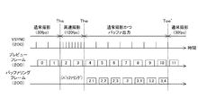
- FIG. 8 is a timing chart showing an example of the operation of the imaging apparatus 100 according to the first embodiment.
- the imaging apparatus 100 When the recording start button is pressed, the imaging apparatus 100 generates a preview frame each time a period of a synchronization signal such as the vertical synchronization signal VSYNC elapses.
- the vertical synchronization signal VSYNC is a periodic signal indicating the timing for generating a frame. Then, the imaging apparatus 100 displays and records a preview frame.
- the imaging apparatus 100 When the scene changes at timing Tc, the period from Ths to The including that timing is set as the high-speed shooting period. During this period, the imaging apparatus 100 generates a frame and buffers it every time a period shorter than that during normal shooting elapses. In addition, the imaging apparatus 100 displays and records a preview frame every time the same period as in normal shooting elapses.
- the imaging apparatus 100 When the high-speed shooting period has elapsed, the imaging apparatus 100 generates, displays, and records a preview frame each time the period of the vertical synchronization signal VSYNC elapses.
- the imaging apparatus 100 After the recording stop operation is performed at the timing Tos, the imaging apparatus 100 generates and displays a preview frame every time the period of the vertical synchronization signal VSYNC elapses. Further, the imaging apparatus 100 takes out the buffering frame from the frame buffer 270 and records it in the recording unit 140 every time the period of the vertical synchronization signal VSYNC elapses.
- the application execution unit 150 refers to the time stamps of the recorded preview frame and buffering frame, rearranges them in the order of shooting, and sets them as recording frames. For example, a case is assumed where high-speed shooting is performed at 120 fps in 1/15 seconds from when the “2” -th preview frame is shot to when the “4” -th preview frame is shot. In this case, seven frames of “2_1”, “2_2”, “2_3”, “3”, “3_1”, “3_2”, and “3_3” are buffered.
- the application execution unit 150 deletes the buffering frame “3” that overlaps the preview frame, and sets the buffering frames “2_1”, “2_2”, and “2_3” between the preview frames “2” and “3”. Insert into. Further, the application execution unit 150 inserts the buffering frames “3_1”, “3_2”, and “3_3” between the preview frames “3” and “4”.
- the image sensor 200 also buffers a frame that overlaps the preview frame as a buffering frame, but may have a configuration in which the overlapping frame is not buffered.
- the frame “3” of “2_1”, “2_2”, “2_3”, “3”, “3_1”, “3_2”, and “3_3” overlaps and is not retained.
- the continuation time of high-speed imaging can be lengthened.
- the application execution unit 150 does not need to delete the buffering frame that overlaps the preview frame.
- the image sensor 200 when recording is stopped, the image sensor 200 outputs a preview frame while outputting a buffering frame in synchronization with the vertical synchronization signal VSYNC. As a result, the display unit 120 can continue displaying the preview frame without interruption even during output of the buffering frame.
- the imaging device 200 interrupts the generation of the preview frame and outputs only the buffering frame when the recording is stopped, the display of the preview frame is interrupted and the next shooting is hindered.
- the display unit 120 can continue displaying the preview frame.
- FIG. 9 is a diagram illustrating an example of a change in the capacity of the frame buffer 270 at the time of shooting according to the first embodiment.
- a period from Ths1 to The1 including the timing is set as a high-speed shooting period.
- the imaging apparatus 100 starts high-speed imaging. Until the timing The1, the imaging apparatus 100 buffers frames in the A area, for example.
- the period from Ths2 to The2 including that timing is set as the second high-speed shooting period.
- the imaging apparatus 100 starts high-speed shooting. Until the timing The2, the imaging apparatus 100 buffers the frame in the B area.
- FIG. 10 is a diagram illustrating an example of a change in the capacity of the frame buffer after the end of shooting according to the first embodiment.
- the image sensor 200 extracts the buffering frame from the frame buffer 270 at a low frame rate and outputs it to the recording unit 140.
- a configuration in which the frame buffer 270 is not divided into the A area and the B area is assumed as a comparative example.
- this comparative example there is no space in the frame buffer 270 at the timing The1 at which the first high-speed shooting is completed in FIG. For this reason, when the user wants to start the second high-speed shooting, the user must press the recording stop button and wait for the frame buffer 270 to be empty, and then press the recording start button again.
- high-speed imaging cannot be performed continuously a plurality of times.
- the imaging apparatus 100 can continuously operate as illustrated in FIGS. 9 and 10. Multiple high-speed shooting can be performed.
- the frame buffer 270 Although two areas are provided in the frame buffer 270, three or more areas can be provided. If the capacity of the frame buffer 270 is constant, the higher the number of areas, the shorter the period of high-speed shooting once, but the number of times of continuous high-speed shooting can be increased.
- FIG. 11 is a graph showing an example of a change in access destination for each area in the first embodiment.
- a write address indicating an address in the area A is generated in order, and the frame is held at these addresses.
- FIG. 12 is a flowchart illustrating an example of the operation of the imaging apparatus 100 according to the first embodiment. This operation starts, for example, when a recording start operation is performed.
- the imaging apparatus 100 performs imaging in the normal imaging mode (step S901), and performs access processing (step S910) for accessing the frame buffer 270.
- the imaging apparatus 100 determines whether or not the high-speed shooting period has started (step S902).
- the imaging apparatus 100 determines whether there is a vacancy in either the A area or the B area (step S903).
- the imaging apparatus 100 executes a high-speed shooting process (step S920) for shooting at a high frame rate.
- step S902 When the high-speed shooting period has not started (step S902: No), when there is no free space in either the A area or the B area (step S903: No), or after step S920, the imaging apparatus 100 stops recording. It is determined whether or not the above operation has been performed (step S904).
- step S904 When a recording stop operation is performed (step S904: Yes), the imaging apparatus 100 shifts to a preview mode (step S905) and performs an access process (step S910). Then, the imaging apparatus 100 determines whether or not a recording start operation has been performed (step S906).
- step S906: No When the recording start operation is not performed (step S906: No), the imaging apparatus 100 repeatedly executes step S910. On the other hand, when an operation for starting recording is performed (step S906: Yes), the imaging apparatus 100 repeatedly executes step S901 and the subsequent steps.
- FIG. 13 is a flowchart illustrating an example of access processing according to the first embodiment.
- the image sensor 200 determines whether or not the high-speed shooting mode is set (step S911). In the case of the high-speed shooting mode (step S911: Yes), the image sensor 200 determines whether or not the generated frame is a preview frame (step S912). If it is a preview frame (step S912: Yes), the imaging device 200 buffers the preview frame as a buffering frame while outputting the preview frame (step S913).
- step S912 when it is not a preview frame (step S912: No), the image sensor 200 buffers the frame as a buffering frame (step S914).
- step S911 When the high-speed shooting mode is not set (step S911: No), the image sensor 200 determines whether or not the preview mode is set (step S915). When the preview mode is set (step S915: Yes), the image sensor 200 outputs a buffering frame (step S916).
- step S915 the image sensor 200 outputs a preview frame (step S917).
- step S913, S914, S916, or S917 the image sensor 200 ends the access process.
- FIG. 14 is a flowchart illustrating an example of high-speed shooting processing according to the first embodiment.
- the imaging apparatus 100 captures an image in the high-speed shooting mode (step S921) and executes an access process (step S910). Then, the imaging apparatus 100 determines whether or not the high-speed shooting period has ended (step S922). When the high-speed shooting period has not ended (step S922: No), the imaging apparatus 100 repeatedly executes step S921 and the subsequent steps. On the other hand, when the high-speed shooting period has ended (step S922: Yes), the imaging apparatus 100 ends the high-speed shooting process.
- the imaging device 200 starts high-speed shooting if any of the plurality of areas in the frame buffer 270 is empty, and thus high-speed shooting is continuously performed. And it can carry out over multiple times.
- the image sensor 200 outputs one buffering frame each time the period of the vertical synchronization signal VSYNC elapses. However, as the number of buffering frames increases, the time until the frame buffer 270 becomes free becomes longer.
- the image sensor 200 according to the first modification of the first embodiment is different from the first embodiment in that the time until the frame buffer 270 is vacant is shortened.
- FIG. 15 is a timing chart showing an example of the operation of the image sensor 200 according to the first modification of the first embodiment.
- the image sensor 200 according to the first modification differs from the first embodiment in that two buffering frames are output every time the period of the vertical synchronization signal VSYNC elapses in the preview mode. Note that the image sensor 200 may output three or more frames each time the period of the vertical synchronization signal VSYNC elapses.
- the imaging element 200 outputs a plurality of frames as the buffering frame every time the period of the vertical synchronization signal elapses.
- the time until the frame buffer 270 becomes empty can be shortened.
- the image sensor 200 outputs a buffering frame when a recording stop operation is performed.
- the frame buffer 270 is full, the next high-speed shooting cannot be started unless the recording is stopped.
- the image sensor 200 in the second modification of the first embodiment is different from the first embodiment in that an empty area is generated in the frame buffer 270 during recording.
- FIG. 16 is a timing chart showing an example of the operation of the image sensor 200 according to the second modification of the first embodiment.
- the image sensor 200 according to the second modification differs from the first embodiment in that a buffering frame is output every time the period of the vertical synchronization signal VSYNC elapses in the normal shooting mode. Thereby, an empty area can be generated in the frame buffer 270 during recording.
- the imaging device 200 outputs the buffering frame during recording in the normal shooting mode.
- An empty area can be generated in the frame buffer 270.
- Second Embodiment> In the first embodiment described above, the image sensor 200 does not output the preview frame and the buffering frame in the order in which they were captured. For this reason, the application execution unit 150 needs to perform editing processing that rearranges the images in the order in which they were shot. As the recording time increases, the processing amount of the application execution unit 150 increases.
- the imaging apparatus 100 according to the second embodiment is different from the first embodiment in that the processing amount of the application execution unit 150 is reduced.
- FIG. 17 is a timing chart showing an example of the operation of the imaging apparatus 100 according to the second embodiment.
- the image sensor 200 captures a frame in synchronization with the vertical synchronization signal VSYNC, outputs the frame to the display unit 120 as a preview frame, and outputs the frame to the recording unit 140 as a recording frame.
- the image sensor 200 In the high-speed shooting mode, the image sensor 200 outputs a preview frame to the display unit 120 at a low frame rate. Further, the image sensor 200 generates a frame at a high frame rate, holds the frame in the frame buffer 270, takes out the frames at a low frame rate in the held order, and outputs them as a recording frame.
- the image sensor 200 stores the preview frame in the frame buffer 270 every time a preview frame is generated. Then, the imaging device 200 takes out the frames from the frame buffer 270 at a low frame rate in the order in which they are held, and outputs them as recording frames. Further, the image sensor 200 outputs a preview frame to the display unit 120 at a low frame rate.
- the image pickup device 200 takes out frames from the frame buffer 270 at a low frame rate in the order in which they are held until the frame buffer 270 becomes empty, and outputs it as a recording frame.
- the imaging device 200 holds the preview frame after high-speed shooting, extracts the frames at the low frame rate in the held order, and outputs them as a recording frame. Recording frames can be output in order. Therefore, the application execution unit 150 does not need to perform the process of rearranging the recording frames in the shooting order, and the processing amount of the application execution unit 150 can be reduced.
- the processing procedure described in the above embodiment may be regarded as a method having a series of these procedures, and a program for causing a computer to execute these series of procedures or a recording medium storing the program. You may catch it.
- a recording medium for example, a CD (Compact Disc), an MD (MiniDisc), a DVD (Digital Versatile Disc), a memory card, a Blu-ray disc (Blu-ray (registered trademark) Disc), or the like can be used.
- this technique can also take the following structures.
- a buffer provided with a plurality of areas;
- An image generating unit that generates an image when the free space in any of the plurality of regions exceeds a predetermined threshold;
- a management unit that holds the image as a buffered image in an area of which the free space exceeds the predetermined threshold among the plurality of areas;
- An image pickup device comprising: an output unit that extracts and outputs the buffered images from the buffer in the order in which the buffered images are held.
- the image generation unit generates the image as a preview image every time a predetermined period elapses in a predetermined normal shooting period, and the plurality of regions in a high-speed shooting period different from the predetermined normal shooting period If any of the free space exceeds the predetermined threshold, the image is generated as a high-speed captured image every time a period shorter than the predetermined period elapses,
- the output unit further outputs the preview image together with the buffered image every time the predetermined period elapses.
- the management unit causes the buffer to hold the preview image together with the buffering image
- a buffer provided with a plurality of areas;
- An image generating unit that generates an image when the free space in any of the plurality of regions exceeds a predetermined threshold;
- a management unit that holds the image as a buffered image in an area of which the free space exceeds the predetermined threshold among the plurality of areas;
- An imaging apparatus comprising: an output unit that extracts and outputs the buffered images from the buffer in the order in which the buffered images are held; and a recording unit that records the output images.
- An image generation procedure for generating an image when the free capacity of any of the plurality of areas in a buffer provided with a plurality of areas exceeds a predetermined threshold;
- a management procedure for holding the image as a buffered image in an area of which the free space exceeds the predetermined threshold among the plurality of areas;
- An image pickup device control method comprising: an output procedure for extracting and outputting the buffered images from the buffer in the order in which the buffered images are held.
Landscapes
- Engineering & Computer Science (AREA)
- Theoretical Computer Science (AREA)
- Physics & Mathematics (AREA)
- General Physics & Mathematics (AREA)
- Multimedia (AREA)
- Signal Processing (AREA)
- General Engineering & Computer Science (AREA)
- Mathematical Physics (AREA)
- Computing Systems (AREA)
- Studio Devices (AREA)
- Image Input (AREA)
- Transforming Light Signals Into Electric Signals (AREA)
Abstract
Description
1.第1の実施の形態(複数の領域のいずれかにバッファリングする例)
2.第2の実施の形態(録画フレームを複数の領域のいずれかにバッファリングして撮影順に出力する例)
[撮像装置の構成例]
図1は、第1の実施の形態における撮像装置100の一構成例を示すブロック図である。この撮像装置100は、画像データ(フレーム)を撮像するものであり、撮像レンズ110、表示部120、制御部130、記録部140、アプリケーション実行部150および再生部160を備える。撮像装置100としては、デジタルスチルカメラやデジタルビデオカメラなどのデジタルカメラの他、撮像機能を持つスマートフォンやパーソナルコンピュータなどが想定される。
図2は、第1の実施の形態における撮像素子200の一構成例を示すブロック図である。この撮像素子200は、走査部210、画素アレイ部220、AD(Analog to Digital)変換部230、前処理部240および管理部250を備える。また、撮像素子200は、メモリコントローラ260、フレームバッファ270、後処理部280および出力インターフェース290を備える。
図3は、第1の実施の形態における前処理部240の一構成例を示すブロック図である。この前処理部240は、ゲイン調整部241、クランプ処理部242およびシーン変化検出部243を備える。
図4は、第1の実施の形態におけるフレームバッファ270の一構成例を示す図である。このフレームバッファ270は、A領域271およびB領域272を含む。A領域271およびB領域272のそれぞれには、N(Nは整数)枚のフレームを保持することができる。
図5は、第1の実施の形態における管理部250の一構成例を示すブロック図である。この管理部250は、タイムスタンプ生成部251およびアドレス管理部252を備える。
図6は、第1の実施の形態における後処理部280の一構成例を示すブロック図である。この後処理部280は、リモザイク処理部281およびスケーリング処理部282を備える。
図12は、第1の実施の形態における撮像装置100の動作の一例を示すフローチャートである。この動作は、例えば、録画開始の操作が行われたときに開始する。撮像装置100は、通常撮影モードで撮影を行い(ステップS901)、フレームバッファ270にアクセスするアクセス処理(ステップS910)を行う。
上述の第1の実施の形態では、撮像素子200は、垂直同期信号VSYNCの周期が経過するたびにバッファリングフレームを1枚ずつ出力していた。しかし、バッファリングフレームの枚数が多くなるほど、フレームバッファ270に空きができるまでの時間が長くなる。この第1の実施の形態の第1の変形例の撮像素子200は、フレームバッファ270に空きができるまでの時間を短くした点において第1の実施の形態と異なる。
上述の第1の実施の形態では、撮像素子200は、録画停止の操作が行われると、バッファリングフレームを出力していた。しかし、この構成では、フレームバッファ270に空きがなくなると、録画が停止されない限り、次の高速撮影を開始することができない。この第1の実施の形態の第2の変形例における撮像素子200は、録画中にフレームバッファ270に空き領域を生じさせる点において第1の実施の形態と異なる。
上述の第1の実施形態では、撮像素子200は、プレビューフレームとバッファリングフレームとを撮影された順に出力していなかった。このため、アプリケーション実行部150は、撮影された順に並び変える編集処理を行う必要があり、録画時間が長くなるほど、アプリケーション実行部150の処理量が増大してしまう。この第2の実施の形態の撮像装置100は、アプリケーション実行部150の処理量を低減した点において第1の実施の形態と異なる。
(1)複数の領域が設けられたバッファと、
前記複数の領域のいずれかの空き容量が所定の閾値を超える場合には画像を生成する画像生成部と、
前記複数の領域のうち空き容量が前記所定の閾値を超える領域に前記画像をバッファリング画像として保持させる管理部と、
前記バッファリング画像が保持された順に前記バッファから前記バッファリング画像を取り出して出力する出力部と
を具備する撮像素子。
(2)前記画像生成部は、所定の通常撮影期間内において所定の周期が経過するたびに前記画像をプレビュー画像として生成し、前記所定の通常撮影期間と異なる高速撮影期間内において前記複数の領域のいずれかの空き容量が前記所定の閾値を超える場合には前記所定の周期より短い周期が経過するたびに前記画像を高速撮影画像として生成し、
前記管理部は、前記高速撮影画像を前記バッファリング画像として保持させる
前記(1)記載の撮像素子。
(3)前記出力部は、前記所定の周期が経過するたびに前記バッファリング画像とともに前記プレビュー画像をさらに出力する
前記(2)記載の撮像素子。
(4)前記管理部は、前記バッファリング画像とともに前記プレビュー画像を前記バッファに保持させ、
前記出力部は、前記バッファリング画像および前記プレビュー画像を当該画像が保持された順に前記バッファから取り出して出力する
前記(2)または(4)に記載の撮像素子。
(5)前記出力部は、所定の操作が行われたときに前記バッファから前記バッファリング画像を取り出して出力する
前記(2)から(4)のいずれかに記載の撮像素子。
(6)前記出力部は、前記高速撮影期間が終了すると前記バッファから前記バッファリング画像を取り出して出力する
前記(2)から(5)のいずれかに記載の撮像素子。
(7)前記出力部は、前記所定の周期が経過するたびに前記バッファリング画像を複数枚取り出して出力する
前記(2)から(6)のいずれかに記載の撮像素子。
(8)複数の領域が設けられたバッファと、
前記複数の領域のいずれかの空き容量が所定の閾値を超える場合には画像を生成する画像生成部と、
前記複数の領域のうち空き容量が前記所定の閾値を超える領域に前記画像をバッファリング画像として保持させる管理部と、
前記バッファリング画像が保持された順に前記バッファから前記バッファリング画像を取り出して出力する出力部と
前記出力された画像を記録する記録部と
を具備する撮像装置。
(9)複数の領域が設けられたバッファ内の前記複数の領域のいずれかの空き容量が所定の閾値を超える場合には画像を生成する画像生成手順と、
前記複数の領域のうち空き容量が前記所定の閾値を超える領域に前記画像をバッファリング画像として保持させる管理手順と、
前記バッファリング画像が保持された順に前記バッファから前記バッファリング画像を取り出して出力する出力手順と
を具備する撮像素子の制御方法。
110 撮像レンズ
120 表示部
130 制御部
140 記録部
150 アプリケーション実行部
160 再生部
200 撮像素子
210 走査部
220 画素アレイ部
230 AD変換部
240 前処理部
241 ゲイン調整部
242 クランプ処理部
243 シーン変化検出部
250 管理部
251 タイムスタンプ生成部
252 アドレス管理部
260 メモリコントローラ
270 フレームバッファ
280 後処理部
281 リモザイク処理部
282 スケーリング処理部
290 出力インターフェース
Claims (9)
- 複数の領域が設けられたバッファと、
前記複数の領域のいずれかの空き容量が所定の閾値を超える場合には画像を生成する画像生成部と、
前記複数の領域のうち空き容量が前記所定の閾値を超える領域に前記画像をバッファリング画像として保持させる管理部と、
前記バッファリング画像が保持された順に前記バッファから前記バッファリング画像を取り出して出力する出力部と
を具備する撮像素子。 - 前記画像生成部は、所定の通常撮影期間内において所定の周期が経過するたびに前記画像をプレビュー画像として生成し、前記所定の通常撮影期間と異なる高速撮影期間内において前記複数の領域のいずれかの空き容量が前記所定の閾値を超える場合には前記所定の周期より短い周期が経過するたびに前記画像を高速撮影画像として生成し、
前記管理部は、前記高速撮影画像を前記バッファリング画像として保持させる
請求項1記載の撮像素子。 - 前記出力部は、前記所定の周期が経過するたびに前記バッファリング画像とともに前記プレビュー画像をさらに出力する
請求項2記載の撮像素子。 - 前記管理部は、前記バッファリング画像とともに前記プレビュー画像を前記バッファに保持させ、
前記出力部は、前記バッファリング画像および前記プレビュー画像を当該画像が保持された順に前記バッファから取り出して出力する
請求項2記載の撮像素子。 - 前記出力部は、所定の操作が行われたときに前記バッファから前記バッファリング画像を取り出して出力する
請求項2記載の撮像素子。 - 前記出力部は、前記高速撮影期間が終了すると前記バッファから前記バッファリング画像を取り出して出力する
請求項2記載の撮像素子。 - 前記出力部は、前記所定の周期が経過するたびに前記バッファリング画像を複数枚取り出して出力する
請求項2記載の撮像素子。 - 複数の領域が設けられたバッファと、
前記複数の領域のいずれかの空き容量が所定の閾値を超える場合には画像を生成する画像生成部と、
前記複数の領域のうち空き容量が前記所定の閾値を超える領域に前記画像をバッファリング画像として保持させる管理部と、
前記バッファリング画像が保持された順に前記バッファから前記バッファリング画像を取り出して出力する出力部と
前記出力された画像を記録する記録部と
を具備する撮像装置。 - 複数の領域が設けられたバッファ内の前記複数の領域のいずれかの空き容量が所定の閾値を超える場合には画像を生成する画像生成手順と、
前記複数の領域のうち空き容量が前記所定の閾値を超える領域に前記画像をバッファリング画像として保持させる管理手順と、
前記バッファリング画像が保持された順に前記バッファから前記バッファリング画像を取り出して出力する出力手順と
を具備する撮像素子の制御方法。
Priority Applications (5)
| Application Number | Priority Date | Filing Date | Title |
|---|---|---|---|
| CN201680084635.1A CN109076146A (zh) | 2016-04-15 | 2016-12-29 | 摄像元件、摄像装置和用于摄像元件的控制方法 |
| EP16898705.5A EP3445031A4 (en) | 2016-04-15 | 2016-12-29 | IMAGE CAPTURE ELEMENT, IMAGE CAPTURE APPARATUS, AND METHOD FOR CONTROLLING IMAGE CAPTURE ELEMENT |
| KR1020187029344A KR20180133414A (ko) | 2016-04-15 | 2016-12-29 | 촬상 소자, 촬상 장치 및 촬상 소자의 제어 방법 |
| US16/092,366 US10645279B2 (en) | 2016-04-15 | 2016-12-29 | Imaging element, imaging apparatus, and control method for imaging element |
| US16/860,932 US11265465B2 (en) | 2016-04-15 | 2020-04-28 | Imaging element, imaging apparatus, and control method for imaging element |
Applications Claiming Priority (2)
| Application Number | Priority Date | Filing Date | Title |
|---|---|---|---|
| JP2016-082083 | 2016-04-15 | ||
| JP2016082083A JP2017192100A (ja) | 2016-04-15 | 2016-04-15 | 撮像素子、撮像装置、および、撮像素子の制御方法 |
Related Child Applications (2)
| Application Number | Title | Priority Date | Filing Date |
|---|---|---|---|
| US16/092,366 A-371-Of-International US10645279B2 (en) | 2016-04-15 | 2016-12-29 | Imaging element, imaging apparatus, and control method for imaging element |
| US16/860,932 Continuation US11265465B2 (en) | 2016-04-15 | 2020-04-28 | Imaging element, imaging apparatus, and control method for imaging element |
Publications (1)
| Publication Number | Publication Date |
|---|---|
| WO2017179249A1 true WO2017179249A1 (ja) | 2017-10-19 |
Family
ID=60041649
Family Applications (1)
| Application Number | Title | Priority Date | Filing Date |
|---|---|---|---|
| PCT/JP2016/089206 WO2017179249A1 (ja) | 2016-04-15 | 2016-12-29 | 撮像素子、撮像装置、および、撮像素子の制御方法 |
Country Status (6)
| Country | Link |
|---|---|
| US (2) | US10645279B2 (ja) |
| EP (1) | EP3445031A4 (ja) |
| JP (1) | JP2017192100A (ja) |
| KR (1) | KR20180133414A (ja) |
| CN (1) | CN109076146A (ja) |
| WO (1) | WO2017179249A1 (ja) |
Cited By (2)
| Publication number | Priority date | Publication date | Assignee | Title |
|---|---|---|---|---|
| EP3764632A4 (en) * | 2018-03-26 | 2021-01-13 | Huawei Technologies Co., Ltd. | METHOD AND ELECTRONIC DEVICE FOR VIDEO RECORDING |
| CN112740662A (zh) * | 2018-09-27 | 2021-04-30 | 富士胶片株式会社 | 成像元件、摄像装置、图像数据输出方法及程序 |
Families Citing this family (8)
| Publication number | Priority date | Publication date | Assignee | Title |
|---|---|---|---|---|
| US9264508B2 (en) | 2011-08-19 | 2016-02-16 | Time Warner Cable Enterprises Llc | Apparatus and methods for reduced switching delays in a content distribution network |
| JP2017192100A (ja) | 2016-04-15 | 2017-10-19 | ソニー株式会社 | 撮像素子、撮像装置、および、撮像素子の制御方法 |
| US10652594B2 (en) | 2016-07-07 | 2020-05-12 | Time Warner Cable Enterprises Llc | Apparatus and methods for presentation of key frames in encrypted content |
| US10958948B2 (en) * | 2017-08-29 | 2021-03-23 | Charter Communications Operating, Llc | Apparatus and methods for latency reduction in digital content switching operations |
| US10939142B2 (en) | 2018-02-27 | 2021-03-02 | Charter Communications Operating, Llc | Apparatus and methods for content storage, distribution and security within a content distribution network |
| US11412136B2 (en) * | 2018-12-07 | 2022-08-09 | Samsung Electronics Co., Ltd. | Apparatus and method for operating multiple cameras for digital photography |
| KR20210092083A (ko) * | 2020-01-15 | 2021-07-23 | 삼성전자주식회사 | 이미지 데이터를 처리하는 전자 장치 및 이미지 데이터 처리 방법 |
| US11470260B1 (en) * | 2020-12-17 | 2022-10-11 | Gopro, Inc. | Image capture device that reduces gaps between captures |
Citations (2)
| Publication number | Priority date | Publication date | Assignee | Title |
|---|---|---|---|---|
| JP2002199328A (ja) * | 2000-10-19 | 2002-07-12 | Canon Inc | 撮像装置、撮像方法、記憶媒体および集積回路 |
| WO2009150828A1 (ja) * | 2008-06-10 | 2009-12-17 | 国立大学法人東北大学 | 固体撮像素子 |
Family Cites Families (15)
| Publication number | Priority date | Publication date | Assignee | Title |
|---|---|---|---|---|
| US4510581A (en) * | 1983-02-14 | 1985-04-09 | Prime Computer, Inc. | High speed buffer allocation apparatus |
| JP3118917B2 (ja) * | 1991-12-06 | 2000-12-18 | キヤノン株式会社 | 画像記録装置及び電子スチル・カメラ |
| US7064784B2 (en) | 2000-10-19 | 2006-06-20 | Canon Kabushiki Kaisha | Image pickup apparatus adapted to carry out parallel operations in a continuous image pickup mode, and a control method |
| JP5130421B2 (ja) | 2006-06-18 | 2013-01-30 | 雅英 田中 | 通信機能を有するデジタルカメラ |
| JP4360399B2 (ja) | 2006-11-30 | 2009-11-11 | ソニー株式会社 | 撮像装置 |
| EP2173088B1 (en) | 2007-07-26 | 2013-12-25 | Panasonic Corporation | Photographing apparatus |
| US8190794B2 (en) * | 2009-10-21 | 2012-05-29 | Texas Instruments Incorporated | Control function for memory based buffers |
| CN102640486B (zh) * | 2009-10-27 | 2015-10-21 | Nec卡西欧移动通信株式会社 | 图像拍摄装置以及图像拍摄方法 |
| US9179103B2 (en) | 2010-09-28 | 2015-11-03 | Alcatel Lucent | System and method for controllably viewing digital video streams captured by surveillance cameras |
| US8886741B2 (en) * | 2011-06-21 | 2014-11-11 | Intel Corporation | Receive queue models to reduce I/O cache consumption |
| JP2013255166A (ja) * | 2012-06-08 | 2013-12-19 | Casio Comput Co Ltd | 画像読取装置及びプログラム |
| US20140232892A1 (en) * | 2013-02-20 | 2014-08-21 | Woodman Labs, Inc. | Digital signal processor buffer management |
| CN104284076A (zh) * | 2013-07-11 | 2015-01-14 | 中兴通讯股份有限公司 | 一种处理预览图像的方法、装置及移动终端 |
| CN104349168A (zh) * | 2014-08-11 | 2015-02-11 | 大连戴姆科技有限公司 | 一种超高速图像实时压缩方法 |
| JP2017192100A (ja) | 2016-04-15 | 2017-10-19 | ソニー株式会社 | 撮像素子、撮像装置、および、撮像素子の制御方法 |
-
2016
- 2016-04-15 JP JP2016082083A patent/JP2017192100A/ja active Pending
- 2016-12-29 KR KR1020187029344A patent/KR20180133414A/ko unknown
- 2016-12-29 CN CN201680084635.1A patent/CN109076146A/zh active Pending
- 2016-12-29 EP EP16898705.5A patent/EP3445031A4/en not_active Withdrawn
- 2016-12-29 WO PCT/JP2016/089206 patent/WO2017179249A1/ja active Application Filing
- 2016-12-29 US US16/092,366 patent/US10645279B2/en active Active
-
2020
- 2020-04-28 US US16/860,932 patent/US11265465B2/en active Active
Patent Citations (2)
| Publication number | Priority date | Publication date | Assignee | Title |
|---|---|---|---|---|
| JP2002199328A (ja) * | 2000-10-19 | 2002-07-12 | Canon Inc | 撮像装置、撮像方法、記憶媒体および集積回路 |
| WO2009150828A1 (ja) * | 2008-06-10 | 2009-12-17 | 国立大学法人東北大学 | 固体撮像素子 |
Non-Patent Citations (1)
| Title |
|---|
| See also references of EP3445031A4 * |
Cited By (6)
| Publication number | Priority date | Publication date | Assignee | Title |
|---|---|---|---|---|
| EP3764632A4 (en) * | 2018-03-26 | 2021-01-13 | Huawei Technologies Co., Ltd. | METHOD AND ELECTRONIC DEVICE FOR VIDEO RECORDING |
| JP2021517415A (ja) * | 2018-03-26 | 2021-07-15 | 華為技術有限公司Huawei Technologies Co.,Ltd. | ビデオ記録方法および電子デバイス |
| JP7139440B2 (ja) | 2018-03-26 | 2022-09-20 | 華為技術有限公司 | ビデオ記録方法および電子デバイス |
| CN112740662A (zh) * | 2018-09-27 | 2021-04-30 | 富士胶片株式会社 | 成像元件、摄像装置、图像数据输出方法及程序 |
| US11463646B2 (en) * | 2018-09-27 | 2022-10-04 | Fujifilm Corporation | Imaging element comprising output circuit that includes first and second output lines, imaging apparatus, image data output method, and program |
| US11785362B2 (en) | 2018-09-27 | 2023-10-10 | Fujifilm Corporation | Imaging element with output circuit that outputs to first and second circuits, imaging apparatus, image data output method, and program |
Also Published As
| Publication number | Publication date |
|---|---|
| US20190166306A1 (en) | 2019-05-30 |
| US20200260003A1 (en) | 2020-08-13 |
| CN109076146A (zh) | 2018-12-21 |
| EP3445031A1 (en) | 2019-02-20 |
| US11265465B2 (en) | 2022-03-01 |
| JP2017192100A (ja) | 2017-10-19 |
| EP3445031A4 (en) | 2019-04-03 |
| KR20180133414A (ko) | 2018-12-14 |
| US10645279B2 (en) | 2020-05-05 |
Similar Documents
| Publication | Publication Date | Title |
|---|---|---|
| WO2017179249A1 (ja) | 撮像素子、撮像装置、および、撮像素子の制御方法 | |
| KR102077967B1 (ko) | 전자 기기 | |
| JP4958758B2 (ja) | 記録装置、再生装置、記録方法、再生方法及びプログラム | |
| JP2009194770A (ja) | 撮像装置、動画再生装置及びそのプログラム | |
| JP2009111518A (ja) | 撮像装置、画像再生装置及びそのプログラム、画像ファイルのデータ構造 | |
| JP2009147743A (ja) | 記録装置、再生装置、記録方法、再生方法及びプログラム | |
| CN101753943B (zh) | 图像处理设备和图像处理方法 | |
| JP2009260748A (ja) | 記憶再生装置 | |
| JP5268539B2 (ja) | 撮像装置及び信号制御方法 | |
| JP2009272921A (ja) | 動画像記録装置、動画像再生装置、動画像記録方法、動画像再生方法および半導体集積回路 | |
| JP2005039792A (ja) | 記録装置及び再生装置 | |
| JP5118465B2 (ja) | 記録装置、再生装置、記録方法、再生方法及びプログラム | |
| JP2010183370A (ja) | 画像再生装置 | |
| JP2018195892A (ja) | 撮像装置 | |
| JP2010187112A (ja) | 画像再生装置 | |
| JP2010187111A (ja) | 撮像装置 | |
| KR101589490B1 (ko) | 디지털 영상 처리기에서 이미지 압축 및 해제 장치 및 방법 | |
| KR20080098735A (ko) | 고속 영상 재생방법 및 이를 적용한 영상재생장치 | |
| JP2019009486A (ja) | 撮像装置 | |
| JP2013058853A (ja) | 動画再生装置、動画再生方法及びプログラム | |
| JP2018195891A (ja) | 撮像装置 | |
| JP5300606B2 (ja) | 撮像装置及びその制御方法 | |
| JP5306068B2 (ja) | 撮像装置及びその制御方法 | |
| JP2012100022A (ja) | 画像処理システム | |
| JP2010245826A (ja) | 電子カメラ |
Legal Events
| Date | Code | Title | Description |
|---|---|---|---|
| ENP | Entry into the national phase |
Ref document number: 20187029344 Country of ref document: KR Kind code of ref document: A |
|
| NENP | Non-entry into the national phase |
Ref country code: DE |
|
| WWE | Wipo information: entry into national phase |
Ref document number: 2016898705 Country of ref document: EP |
|
| ENP | Entry into the national phase |
Ref document number: 2016898705 Country of ref document: EP Effective date: 20181115 |
|
| 121 | Ep: the epo has been informed by wipo that ep was designated in this application |
Ref document number: 16898705 Country of ref document: EP Kind code of ref document: A1 |