WO2017175795A1 - 熱拡散率測定装置、熱拡散率測定方法およびプログラム - Google Patents
熱拡散率測定装置、熱拡散率測定方法およびプログラム Download PDFInfo
- Publication number
- WO2017175795A1 WO2017175795A1 PCT/JP2017/014223 JP2017014223W WO2017175795A1 WO 2017175795 A1 WO2017175795 A1 WO 2017175795A1 JP 2017014223 W JP2017014223 W JP 2017014223W WO 2017175795 A1 WO2017175795 A1 WO 2017175795A1
- Authority
- WO
- WIPO (PCT)
- Prior art keywords
- thermal diffusivity
- detection
- temperature
- measurement object
- heating
- Prior art date
Links
- 238000005259 measurement Methods 0.000 title claims abstract description 62
- 238000009792 diffusion process Methods 0.000 title claims abstract description 13
- 238000000691 measurement method Methods 0.000 title abstract description 5
- 238000001514 detection method Methods 0.000 claims abstract description 103
- 238000010438 heat treatment Methods 0.000 claims abstract description 62
- 230000035945 sensitivity Effects 0.000 claims abstract description 27
- 238000000034 method Methods 0.000 claims description 29
- 230000010354 integration Effects 0.000 claims description 2
- 239000008186 active pharmaceutical agent Substances 0.000 abstract description 6
- 230000000737 periodic effect Effects 0.000 description 17
- 238000001931 thermography Methods 0.000 description 16
- 229920000049 Carbon (fiber) Polymers 0.000 description 7
- 239000004917 carbon fiber Substances 0.000 description 7
- VNWKTOKETHGBQD-UHFFFAOYSA-N methane Chemical compound C VNWKTOKETHGBQD-UHFFFAOYSA-N 0.000 description 6
- 239000011208 reinforced composite material Substances 0.000 description 6
- 239000000463 material Substances 0.000 description 4
- OKTJSMMVPCPJKN-UHFFFAOYSA-N Carbon Chemical compound [C] OKTJSMMVPCPJKN-UHFFFAOYSA-N 0.000 description 2
- 238000010586 diagram Methods 0.000 description 2
- 229910002804 graphite Inorganic materials 0.000 description 2
- 239000010439 graphite Substances 0.000 description 2
- 230000001678 irradiating effect Effects 0.000 description 2
- 230000005855 radiation Effects 0.000 description 2
- 238000007707 calorimetry Methods 0.000 description 1
- 239000004918 carbon fiber reinforced polymer Substances 0.000 description 1
- 239000000835 fiber Substances 0.000 description 1
- 230000017525 heat dissipation Effects 0.000 description 1
- WPYVAWXEWQSOGY-UHFFFAOYSA-N indium antimonide Chemical compound [Sb]#[In] WPYVAWXEWQSOGY-UHFFFAOYSA-N 0.000 description 1
- 230000003287 optical effect Effects 0.000 description 1
- 230000000644 propagated effect Effects 0.000 description 1
- 230000001902 propagating effect Effects 0.000 description 1
- 239000004065 semiconductor Substances 0.000 description 1
- 229920005992 thermoplastic resin Polymers 0.000 description 1
Images


Classifications
-
- G—PHYSICS
- G01—MEASURING; TESTING
- G01N—INVESTIGATING OR ANALYSING MATERIALS BY DETERMINING THEIR CHEMICAL OR PHYSICAL PROPERTIES
- G01N25/00—Investigating or analyzing materials by the use of thermal means
- G01N25/18—Investigating or analyzing materials by the use of thermal means by investigating thermal conductivity
-
- G—PHYSICS
- G01—MEASURING; TESTING
- G01N—INVESTIGATING OR ANALYSING MATERIALS BY DETERMINING THEIR CHEMICAL OR PHYSICAL PROPERTIES
- G01N33/00—Investigating or analysing materials by specific methods not covered by groups G01N1/00 - G01N31/00
- G01N33/0003—Composite materials
-
- G—PHYSICS
- G01—MEASURING; TESTING
- G01N—INVESTIGATING OR ANALYSING MATERIALS BY DETERMINING THEIR CHEMICAL OR PHYSICAL PROPERTIES
- G01N33/00—Investigating or analysing materials by specific methods not covered by groups G01N1/00 - G01N31/00
Definitions
- the present invention relates to a thermal diffusivity measuring apparatus, a thermal diffusivity measuring method and a program used for measuring the thermal diffusivity of a sample.
- carbon fiber reinforced composite materials have been widely used in electronic devices and the like as materials having high thermal conductivity, anisotropy and high specific rigidity.
- a large difference occurs in thermal diffusivity due to anisotropy generated by the orientation of carbon fibers.
- Carbon fiber reinforced composite materials generally have a high thermal diffusivity in the in-plane direction because the fibers are oriented in the in-plane direction of the material. Also, due to the downsizing of electronic devices, heat-dissipating carbon fiber reinforced composite materials are used for heat dissipation of CPUs and batteries, but these heat-dissipating materials also have strong atomic bonds arranged in the in-plane direction. The thermal diffusivity in the in-plane direction is high.
- an isotropic sample having the same thermal diffusivity in both the in-plane direction and the thickness direction is targeted, and it does not take into account that it takes time for the thermal diffusion in the thickness direction. Therefore, in the conventional general thermal diffusivity measurement method, a correct value cannot be measured in the case of an anisotropic sample having a thickness of 100 ⁇ m or more.
- Non-Patent Document 1 discloses a method using the AC calorimetry method. In this thermal diffusivity measuring method, the three-dimensional theory is applied, and the thermal diffusivity in the in-plane direction and the thickness direction is analyzed simultaneously by fitting the solution of the heat conduction equation to the measurement result.
- Patent Document 1 discloses a thermal diffusivity measuring device developed by the inventors of the present application.
- the thermal diffusivity measuring device disclosed in Patent Document 1 heats the surface of a plate-like object to be measured by laser spot periodic heating, detects the temperature change of the back surface of the object to be measured by infrared thermography, and changes the temperature. And the heating cycle are calculated, and the thermal diffusivity of the measurement object is calculated based on the calculated phase delay.
- thermocouple used for this type of measurement is very thin and requires great care in handling the thermocouple itself. As a result, sample adjustment and measurement error by the operator are also large.
- thermocouple instead of a thermocouple, a configuration using a radiation thermometer using InSb or the like that can measure the sample temperature in a non-contact manner as a detection element is conceivable.
- a radiation thermometer is arranged at a distance from the sample, the measurement of the AC temperature of the sample is performed on a region having a spread due to the configuration of the optical system, resulting in a decrease in accuracy. There was a problem that.
- the thermal diffusivity measuring device described in Patent Document 1 can accurately measure the thermal diffusivity in the in-plane direction and the thermal diffusivity in the thickness direction of a carbon fiber reinforced composite material having a thickness of about 130 ⁇ m.
- measurement of a thicker measurement object has been demanded, and even the thermal diffusivity measuring device described in Patent Document 1 may be difficult to cope with.
- an object of the present invention is to provide a thermal diffusivity measuring apparatus, a thermal diffusivity measuring method, and a program that can suppress a decrease in accuracy even if temperature is detected without contact. Furthermore, another object of the present invention is to provide a thermal diffusivity with high accuracy even for a measurement object having anisotropy that has a large difference in thermal diffusivity between the in-plane direction and the thickness direction and is thick. An object of the present invention is to provide a thermal diffusivity measuring device, a thermal diffusivity measuring method, and a program that can be measured.
- the thermal diffusivity measuring device of the present invention comprises a heating means for periodically heating a heating location on the surface of a measurement object having a front surface and a back surface, and the back surface of the measurement object.
- a non-contact temperature sensor that detects the temperature of the detected portion in a non-contact manner, and calculates a phase lag of a detection temperature cycle by the non-contact temperature sensor with respect to a heating cycle by the heating means, and the measurement based on the calculated phase lag
- Thermal diffusivity calculating means for calculating the thermal diffusivity of the object, wherein the thermal diffusivity calculating means obtains the intensity of the detection sensitivity distribution at the detection location for the detection temperature of the non-contact temperature sensor, and the detection location
- the phase of the detected temperature cycle and the intensity of the obtained detection sensitivity distribution are integrated to calculate the phase lag at the detection location and calculate the heat of the measurement object. Characterized by calculating the Chiritsu.
- the thermal diffusivity measuring method of this invention measures the thermal diffusivity of the said measurement object by heating the surface of the measurement object which has a surface and a back surface, and detecting the temperature of the back surface of the said measurement object.
- the intensity of the detection sensitivity distribution at the detection location is obtained for the temperature detected in the temperature detection step, and the phase of the detection temperature cycle at the detection location and the strength of the detected detection sensitivity distribution are obtained.
- the inventors of the present application calculate the thermal diffusivity using the value obtained by integrating not only the temperature of a specific measurement point, but also the detected temperature of the surroundings, to detect the temperature of the measurement object. It has been found that the thermal diffusivity in the in-plane direction and the thickness direction can be accurately measured even for a measurement object having anisotropy that is greatly different from that in the thickness direction and having a large thickness.
- the thermal diffusivity measuring device and the measuring method of the present invention obtain the detection temperature in a range of detection sensitivity distribution centered on the detection location, and the phase of the detection temperature cycle at the detection location and the measurement temperature By integrating the detection temperature within the detection sensitivity distribution, the phase lag at the detection location is calculated, and the thermal diffusivity of the measurement object is calculated.
- the measurement object may have a plate shape, a rod shape, or another shape.
- the detected temperature in the detection sensitivity distribution is obtained from the full width at half maximum of the detected temperature at the detection location. According to the knowledge of the inventors of the present application, the thermal diffusivity in the in-plane direction and the thickness direction of the measurement object can be measured more accurately by adopting this configuration.
- the heating means is a laser irradiation unit that heats by laser irradiation
- the laser irradiation unit is a Gaussian beam whose intensity is modulated at a predetermined angular frequency. It is preferable to heat.
- the heated portion is heated with a Gaussian beam whose intensity is modulated at a predetermined angular frequency.
- the measurement object was irradiated in the case of laser irradiation. Since the intensity distribution in the in-plane direction was close to a Gaussian distribution, a Gaussian beam in which laser irradiation was intensity-modulated at a predetermined angular frequency was used. With this configuration, the thermal diffusivity in the in-plane direction and the thickness direction of the measurement object can be measured more accurately.
- the thermal diffusion measurement program of the present invention is executed by a computer, and uses the thermal diffusivity measuring device to heat the surface of the measurement object having the front surface and the back surface, and detects the temperature of the back surface of the measurement object.
- a thermal diffusion measurement program for measuring the thermal diffusivity of the measurement object by periodically heating the surface of the measurement object in a non-contact manner by a thermal diffusivity measurement device; Detect the temperature of the detection location on the back surface in a non-contact manner, obtain the intensity of the detection sensitivity distribution at the detection location for the detected temperature, and integrate the phase of the detection temperature cycle at the detection location and the intensity of the detection sensitivity distribution
- the thermal diffusivity of the measurement object is calculated by calculating the phase lag between the heating cycle and the detection temperature cycle at the detection location.
- the program makes it possible to execute the thermal diffusivity measuring apparatus and the thermal diffusivity measuring method.
- Explanatory drawing which shows the structure of the thermal diffusivity measuring apparatus of this embodiment.
- Explanatory drawing which shows the state of a heating location and a detection location when a temperature wave is produced in the heating location of a sample.
- (A) is explanatory drawing which shows the state of the temperature wave in a sample at the time of irradiating the laser beam to the heating location of a sample.
- (B) is explanatory drawing which shows the image of the phase delay of the temperature wave detected at a detection location, and a heating wave.
- Explanatory drawing which shows the phase delay of a temperature wave, and the intensity
- (A) And (B) is explanatory drawing which shows the data at the time of calculating
- the thermal diffusivity measuring apparatus 1 of this embodiment includes a laser irradiation unit 2 as a heating unit, an infrared thermography 3 as a non-contact temperature sensor, and a computer 4 as a thermal diffusivity calculating unit.
- the computer 4 stores a program for operating the thermal diffusivity measuring device 1 to execute the thermal diffusivity measuring method.
- the thermal diffusivity measuring apparatus 1 includes a holder 6 for holding a plate-like sample 5 as a measurement object, the holder 6 in the X direction and the Y direction (both in-plane directions of the sample 5), and further in the Z direction.
- An XYZ stage 7 that moves in the thickness direction of the sample 5 is provided.
- the laser irradiation unit 2 uses a semiconductor laser device in this embodiment, and is arranged so as to heat the surface of the sample 5 (the left side surface of the sample 5 in FIG. 1).
- the laser irradiation unit 2 changes the intensity by changing the current supplied to the apparatus when irradiating the laser beam.
- the heating unit includes a first mirror 8, an acoustooptic device 9, a second mirror 10, a beam expander 11, and a microscope 12.
- the first mirror 8 and the second mirror 10 reflect the laser beam emitted from the laser irradiation unit 2 and guide it to the beam expander 11.
- the acoustooptic device 9 is connected to a periodic signal generator 13 and receives a periodic signal transmitted from the periodic signal generator 13 and converts a laser beam emitted from the laser irradiation unit 2 into a periodic signal. It is.
- the frequency of the laser beam emitted from the laser irradiation unit 2 is set to 0.005 Hz to 300 Hz.
- the beam expander 11 expands the beam diameter of the laser beam guided by the second mirror 10.
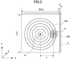
- the laser beam is irradiated as a spot on the heating spot H on the surface of the sample 5 through the microscope 12 provided on the XY stage 14 (see FIG. 2).
- the laser beam applied to the heated portion H of the sample 5 is configured to be a so-called Gaussian beam.
- the Gaussian beam in the present embodiment is formed by modulating the intensity of the laser beam at a predetermined angular frequency in the laser irradiation unit 2.
- this angular frequency is 2 ⁇ f.
- the infrared thermography 3 is a device that can acquire heat generated from the surface of a measurement object in a non-contact manner as an image and measure the temperature from the image.
- the infrared thermography 3 is arranged so as to measure the temperature of the detection portion S on the back surface of the sample 5.
- the infrared thermography 3 is connected to the periodic signal generator 13 and the lock-in amplifier 15, and transmits temperature data to the computer 4 through the lock-in amplifier 15 as a periodic signal.
- the lock-in amplifier 15 is a phase of the heating cycle obtained by the infrared thermography 3 with respect to the heating cycle by the laser irradiation unit 2 from the temperature modulation signal transmitted from the infrared thermography 3 and the reference signal transmitted from the periodic signal generator 13. It is a device that detects a delay.
- the periodic signal generator 13 is a so-called function generator that can generate an AC signal having an arbitrary frequency and waveform.
- a periodic signal is transmitted to the acoustooptic device 9 and the infrared thermography 3 under the control of the computer 4.
- the LED 16 and the CCD camera 17 are configured to visually check the surface state of the sample 5 through the microscope 12.
- the XYZ stage 7 and the XY stage 14 are mounted on a rail 18 provided in the thermal diffusivity measuring apparatus 1.
- the thermal diffusivity measuring method of this embodiment is comprised from each process of a heating process, a temperature detection process, and a calculation process.
- a user who performs measurement inputs parameters necessary for measuring the thermal diffusivity into the thermal diffusivity measuring apparatus 1. For example, the frequency of the laser, the laser power, the distance between the microscope 12 and the sample 5, the interval between measurement points by the infrared thermography 3, the thickness of the sample, the external dimensions of the sample, and the like.
- the sample 5 that is a measurement object for measuring the thermal diffusivity is a graphite sheet (carbon fiber reinforced composite material) or CFRTP (carbon fiber reinforced thermoplastic resin), and has an anisotropic thermal diffusivity.
- the thermal diffusivity ax, ay in the in-plane direction (X direction and Y direction) is different from the thermal diffusivity az in the thickness direction (z direction).
- the sample 5 in this embodiment has the same thermal diffusivity in the X direction and the Y direction.
- the sample 5 is 50 mm in length (Len in FIG. 2) ⁇ 50 mm in width (Wid in FIG. 2) and has a thickness d of 400 ⁇ m.
- the size of the sample 5 can be 10 mm or more in a size that can be attached to the thermal diffusivity measuring apparatus 1.
- the sample 5 having a thickness of 0.01 mm to 2 mm can be used.
- a laser beam is irradiated from the laser irradiation unit 2, reflected by the first mirror 8, and introduced into the acoustooptic device 9.
- the laser beam is converted into a periodic heating wave by a periodic signal from the periodic signal generator 13 controlled by the computer 4.
- the laser beam that has passed through the acoustooptic device 9 is reflected by the second mirror 10, the beam diameter is enlarged by the beam expander 11, and the heated portion H on the surface of the sample 5 is irradiated from the microscope 12.
- the temperature of the detection portion S on the back surface of the sample 5 is detected by the infrared thermography 3 in a non-contact manner.
- the temperature of the detection location S of the sample 5 is acquired as an image.
- the image data since the heating location H is periodically heated by the laser beam, and the temperatures of the heating location H and the detection location S change periodically, the image data changes periodically. It becomes.
- a periodic signal is input to the infrared thermography 3 from the periodic signal generator 13 and transmitted to the computer 4 via the lock-in amplifier 15 together with the acquired image data.
- the image data acquired in the infrared thermography 3 is continuously fetched and calculated based on a frame rate at a predetermined interval, and the temperature changes every moment. Image data averaged from the amount of change is created.
- the computer 4 calculates the heating cycle of the laser beam that heated the sample 5 in the heating step and the detection temperature cycle of the image data detected by the infrared thermography 3 in the temperature detection step and passed through the lock-in amplifier 15.
- the phase delay ⁇ ′ is calculated. Further, the computer 4 obtains the thermal diffusivity of the sample 5 from the phase delay ⁇ ′.
- the laser beam L irradiated from the microscope 12 is irradiated to the heating spot H on the surface side of the sample 5.
- the laser beam L is a periodic heating wave, and as shown in FIGS. 2 and 3, the temperature wave TW propagates inside the sample 5 and spreads around.
- the temperature wave TW propagated from the heating location H is detected at the detection location S.
- the temperature wave TW generated by heating at the heating location H is detected with a phase delay.
- a signal is detected within a detection sensitivity distribution DS in the detection location S.
- FIG. 4 is a diagram schematically showing the relationship between the phase delay ⁇ of the temperature wave TW and the intensity P of the detection sensitivity distribution in the X direction.
- the temperature wave TW generated at the heating location H attenuates as it propagates through the sample 5 and is detected at the detection location S.
- the detection location S is detected.
- the temperature wave TW is detected in a certain range instead of one point.
- the range is the detection sensitivity distribution DS shown in FIG. 4, and as shown in FIG. 4, the level of the detected temperature signal has a mountain shape with the center of the detection location S as the apex.
- the center coordinates (x ′, y ′, z ′) of the heating location H are the origin, and the coordinates of the center of the detection location S are (x, y, z).
- the term “heating location H” or “detection location S” includes the case of each center.
- the sample 5 having the same thermal diffusivity is used in the X direction and the Y direction. Therefore, the thermal diffusivity ax in the X direction is the same as the thermal diffusivity ay in the Y direction.
- the temperature T at a certain time point t at which the detection point is present can be expressed by the following equation (1).
- Equation (1) is a thermal distance from the center coordinate of the heating location H to the center coordinate of the detection location S, and is represented by the following equation (2).
- k in the equation (1) is the wave number of the temperature wave having the frequency f propagating inside the sample 5, and is represented by the following equation. Further, ⁇ is an angular frequency (2 ⁇ f) at the time of heating modulation.
- phase ⁇ of the detection temperature cycle at the detection location S is expressed by the following equation (5).
- l is the distance in the in-plane direction from the center coordinates (x ′, y ′, z ′) of the heating location H, and is r in this embodiment.
- k shows a wave number in (5) Formula.
- the intensity P of the detection sensitivity distribution DS at the detection location S is expressed by the following equation (6).
- R in equation (6) is the standard deviation of the normal distribution of the detected temperature signal, and is represented by the following equation (7). Further, W in Expression (7) is obtained from the full width at half maximum of the detection sensitivity distribution DS.
- phase delay ⁇ ′ considering the detection sensitivity distribution is obtained by the following equation (8) by convolving and integrating the phase delay ⁇ and the intensity P of the detection sensitivity distribution.
- the above calculation is performed by the program stored in the computer 4 as the calculation means.
- the computer 4 performs the calculation at a plurality of measurement points, and plots the result on the graph shown in FIG. 5 (AR in FIG. 5).
- FIG. 5 AR in FIG. 5
- fitting to a graph showing the relationship between the distance r in the X direction and the measured phase delay ⁇ ′ is performed. Determine the thermal diffusivity ar in the direction.
- curves a (H) and a (L) are obtained by storing the results of measurement using a sample having a known thermal diffusivity in the thermal diffusivity measuring apparatus 1.
- a curve a (H) shows a state where the thermal diffusivity in the in-plane direction is high
- a curve a (L) shows a state where the thermal diffusivity in the in-plane direction is low.
- the arrow in the vicinity of the curve a (H) indicates a state of fitting so that the thermal diffusivity in the in-plane direction is low
- the arrow in the vicinity of the curve a (L) has a high thermal diffusivity in the in-plane direction.
- a state of fitting so as to be in a state is shown.
- the calculation for any of the above-mentioned fittings is performed by the computer 4, and the thermal diffusivity of the straight line that fits the plotted measurement result is set as the thermal diffusivity of the sample 5.
- FIG. 6A and 6 (B) are explanatory diagrams showing data when the thermal diffusivity of CFRTP is obtained by fitting in the procedure shown in FIG.
- the measurement is performed with the frequency of the laser emitted from the laser irradiation unit 2 set to 0.01 Hz.
- FIG. 6B measurement is performed with the frequency set to 0.05 Hz.
- the black dots are actual measured values, and the solid line is the fitting result.
- the thermal diffusivity measuring apparatus 1 of the present embodiment is able to normally fit the results of measuring the same sample at a plurality of frequencies. confirmed.
- the measurement method for the sample 5 having the same thermal diffusivity ax and ay in the in-plane direction has been described, but in the case of a sample having anisotropy of the thermal diffusivity in the in-plane direction, By considering this anisotropy in the above calculation formula, the same calculation as in the above embodiment can be performed.
- the thermal diffusivity ay in the Y direction can be calculated as a value obtained by multiplying ax by an anisotropic ratio.
- the graphite sheet and CFRTP were used as the sample 5, it is not restricted to this, Even if it measures thermal diffusivity about the sample which has anisotropy or does not have anisotropy Good.
- the Gaussian beam has an angular frequency of 2 ⁇ f.
- the present invention is not limited to this and may have other values.
- SYMBOLS 1 Thermal diffusivity measuring apparatus, 2 ... Laser irradiation part, 3 ... Infrared thermography (non-contact temperature sensor), 4 ... Computer, 5 ... Sample, 6 ... Holder, 8 ... 1st mirror, 7 ... XYZ stage, 9 ... Acousto-optic element, 10 ... second mirror, 11 ... beam expander, 12 ... microscope, 13 ... periodic signal generator, 14 ... XY stage, 15 ... lock-in amplifier, 16 ... LED, 17 ... CCD camera, 18 ... Rail, H ... heating location, L ... laser beam, S ... detection location, TW ... temperature wave.
Landscapes
- Chemical & Material Sciences (AREA)
- Health & Medical Sciences (AREA)
- Life Sciences & Earth Sciences (AREA)
- General Health & Medical Sciences (AREA)
- Analytical Chemistry (AREA)
- Biochemistry (AREA)
- Physics & Mathematics (AREA)
- General Physics & Mathematics (AREA)
- Immunology (AREA)
- Pathology (AREA)
- Engineering & Computer Science (AREA)
- Food Science & Technology (AREA)
- Medicinal Chemistry (AREA)
- Investigating Or Analyzing Materials Using Thermal Means (AREA)
- Radiation Pyrometers (AREA)
Abstract
【課題】面内方向と厚み方向との熱拡散率が大きく異なる異方性を有し、且つ厚みの厚い測定対象物であっても、高い精度で熱拡散率を測定することができる熱拡散率測定装置、熱拡散率測定方法およびプログラムを提供する。 【解決手段】熱拡散率測定方法において、平板状の試料の加熱箇所Hにおいて周期的に変化する温度波を生じさせるとともに、非接触温度センサにより試料の検出箇所Sにおいて温度波を検出する。そして、非接触温度センサの検出感度分布DSを考慮して検出箇所Sの温度波の位相遅れを検出し、この位相遅れを用いて試料の面内方向の熱拡散率を測定する。
Description
本発明は、試料の熱拡散率の測定に用いられる熱拡散率測定装置、熱拡散率測定方法およびプログラムに関する。
近年、電子機器などにおいては、高熱伝導、異方性、高比剛性の素材として炭素繊維強化複合材が広く採用されている。このような炭素繊維強化複合材においては炭素繊維の配向により発生する異方性により、熱拡散率に大きな差異が生じることが知られている。
炭素繊維強化複合材は、一般的に材料の面内方向に繊維が配向するため、面内方向の熱拡散率が高い。また、電子機器の小型化により、CPUやバッテリーの放熱のために放熱用の炭素繊維強化複合材が用いられるが、これらの放熱材料も面内方向に強固な原子結合が配列しているために、面内方向の熱拡散率が高い。
一般的な熱拡散率測定方法では、熱拡散率が面内方向及び厚み方向共に等しい等方性の試料を対象としており、厚み方向に熱拡散の時間がかかることを考慮していない。よって、従来の一般的な熱拡散率測定方法では、試料の厚みが100μm以上の異方性のある試料の場合、正しい値を測定することができない。
この種の異方性のある素材の熱拡散率測定法として、例えば、非特許文献1にACカロリメトリ法を用いた方法が開示されている。この熱拡散率測定法では、3次元理論を適用し、その熱伝導方程式の解を測定結果にフィッティングさせることで面内方向及び厚み方向の熱拡散率を同時に解析している。
また、特許文献1には、本願発明者等が開発した熱拡散率測定装置が開示されている。この特許文献1に開示された熱拡散率測定装置は、板状の測定対象物の表面をレーザスポット周期加熱により加熱し、測定対象物の裏面の温度変化を赤外線サーモグラフィにより検出し、当該温度変化と加熱周期との位相遅れを算出し、算出された位相遅れに基づいて測定対象物の熱拡散率を演算するものである。
長野方星、加藤英幸、大西晃、長坂雄次著「レーザ加熱式acカロリメトリ法による異方性グラファイトシートの温度伝導率測定」日本伝熱シンポジウム講演論文集37th Vol.3 P901-902、2000年発行
上記非特許文献1の熱拡散率測定法では、銀ペーストにより試料に固定した熱電対を用いて試料温度を測定するので、試料への熱電対の固定、取り外しが煩雑であった。この種の測定に用いられる熱電対は非常に細く熱電対自体の扱いも多大な注意を要する。結果的に試料調整や作業者による測定誤差も大きい。
そこで、熱電対に代えて、非接触で試料温度の測定が可能なInSbなどを検出素子とする放射温度計を用いる構成が考えられる。しかしながら、このような放射温度計では、試料と距離をあけて配置されることから、試料の交流温度の測定が、光学系の構成により広がりをもった領域に対して行われるため精度が低下してしまうという問題があった。
一方、特許文献1記載の熱拡散率測定装置は、130μm程度の厚みの炭素繊維強化複合材の面内方向の熱拡散率及び厚み方向の熱拡散率を正確に測定することができる。しかしながら、近年ではさらに厚い測定対象物の測定が求められており、特許文献1に記載の熱拡散率測定装置でも対応が困難となる場合がある。
そこで、本発明は、非接触で温度検出しても精度の低下を抑制できる熱拡散率測定装置、熱拡散率測定方法およびプログラムを提供することを目的とする。さらに、本発明の他の目的は、面内方向と厚み方向との熱拡散率が大きく異なる異方性を有し、且つ厚みの厚い測定対象物であっても、高い精度で熱拡散率を測定することができる熱拡散率測定装置、熱拡散率測定方法およびプログラムを提供することにある。
上記目的を達成するために、本発明の熱拡散率測定装置は、表面と裏面を有する測定対象物の表面において加熱箇所を非接触で周期的に加熱する加熱手段と、前記測定対象物の裏面において検出箇所の温度を非接触で検出する非接触温度センサと、前記加熱手段による加熱周期に対する前記非接触温度センサによる検出温度周期の位相遅れを算出し、算出された位相遅れに基づいて前記測定対象物の熱拡散率を演算する熱拡散率演算手段とを備え、前記熱拡散率演算手段は、前記非接触温度センサの検出温度について前記検出箇所における検出感度分布の強度を求め、前記検出箇所における検出温度周期の位相と、求められた検出感度分布の強度とを積分処理することにより、前記検出箇所における位相遅れを算出して前記測定対象物の熱拡散率を演算することを特徴とする。
また、本発明の熱拡散率測定方法は、表面と裏面を有する測定対象物の表面を加熱し、前記測定対象物の裏面の温度を検出することにより前記測定対象物の熱拡散率を測定する方法であって、前記測定対象物の表面の加熱箇所を非接触で周期的に加熱する加熱工程と、前記測定対象物の裏面において検出箇所の温度を非接触で検出する温度検出工程と、前記加熱工程における加熱周期に対する前記温度検出工程における検出温度周期の位相遅れを算出し、算出された位相遅れに基づいて前記測定対象物の熱拡散率を演算する演算工程とを有し、前記演算工程において、前記温度検出工程で検出された温度について前記検出箇所における検出感度分布の強度を求め、前記検出箇所における検出温度周期の位相と、求められた検出感度分布の強度とを積分処理することにより、前記検出箇所における位相遅れを算出して前記測定対象物の熱拡散率を演算することを特徴とする。
本願発明者等は、測定対象物の温度検出を、特定の測定点の温度のみならず、その周囲の検出温度を積分処理した値を用いて熱拡散率を演算することにより、面内方向と厚み方向との熱拡散率が大きく異なる異方性を有し、且つ厚みの厚い測定対象物であっても、正確に面内方向及び厚み方向の熱拡散率を測定できることを知見した。本発明の熱拡散率測定装置及び測定方法は、上記知見に鑑みて、前記検出温度を、検出箇所を中心とする検出感度分布の範囲で取得し、当該検出箇所における検出温度周期の位相と前記検出感度分布内の検出温度とを積分処理することにより、前記検出箇所における位相遅れを算出して前記測定対象物の熱拡散率を演算している。ここで、測定対象物は、表面と裏面を有しているものであれば、板状のものでもよく、棒状のものやその他の形状を有しているものであってもよい。
また、本発明の熱拡散率測定装置及び測定方法においては、前記検出感度分布内の検出温度が前記検出箇所における検出温度の半値全幅から求めることが好ましい。本願発明者等の知見によれば、当該構成とすることにより、より正確に測定対象物の面内方向及び厚み方向の熱拡散率を測定できる。
また、本発明の熱拡散率測定装置においては、前記加熱手段がレーザの照射により加熱を行うレーザ照射部であり、前記レーザ照射部が前記加熱箇所を所定の角周波数で強度変調したガウシアンビームで加熱することが好ましい。また、本発明の熱拡散率測定方法では、前記加熱工程において、前記加熱箇所を所定の角周波数で強度変調したガウシアンビームで加熱することが好ましい。
従来は、レーザ照射で測定対象物を加熱した際に、加熱箇所を点としてとらえて演算を行っていたが、本願発明者等の知見によれば、レーザ照射の場合、測定対象物に照射した際の面内方向の強度分布がガウス分布に近いことから、レーザ照射を所定の角周波数で強度変調したガウシアンビームとした。当該構成により、より正確に測定対象物の面内方向及び厚み方向の熱拡散率を測定できる。
また、本発明の熱拡散測定用プログラムは、コンピュータにより実行され、熱拡散率測定装置を用いて、表面と裏面を有する測定対象物の表面を加熱し、前記測定対象物の裏面の温度を検出することにより前記測定対象物の熱拡散率を測定する熱拡散測定用プログラムであって、熱拡散率測定装置により前記測定対象物の表面を非接触で周期的に加熱し、前記測定対象物の裏面において検出箇所の温度を非接触で検出し、検出された温度について前記検出箇所における検出感度分布の強度を求め、前記検出箇所における検出温度周期の位相と、前記検出感度分布の強度とを積分処理することにより、前記検出箇所における加熱周期と検出温度周期との位相遅れを算出して前記測定対象物の熱拡散率を演算することを特徴とする。当該プログラムにより、上記熱拡散率測定装置及び熱拡散率測定方法を実行することが可能となる。
本発明の熱拡散率測定装置、熱拡散率測定方法、及び熱拡散率測定プログラムの一実施形態について図面を参照して説明する。本実施形態の熱拡散率測定装置1は、図1に示すように、加熱手段としてのレーザ照射部2と非接触温度センサとしての赤外線サーモグラフィ3と、熱拡散率演算手段としてのコンピュータ4とを備えている。本実施形態では、このコンピュータ4内に、熱拡散率測定装置1を作動させて熱拡散率測定方法を実行するプログラムが記憶されている。
また、熱拡散率測定装置1は、測定対象物である板状の試料5を保持するホルダ6と、このホルダ6をX方向とY方向(共に試料5の面内方向)、さらにはZ方向(試料5の厚み方向)に移動させるXYZステージ7を備えている。
レーザ照射部2は、本実施形態では半導体レーザ装置を用いており、試料5の表面(図1において試料5の左側の面)を加熱するように配置されている。また、レーザ照射部2は、レーザビームを照射する際に、装置に供給される電流を変化させて強度を変化させるものである。
また、加熱手段としては、レーザ照射部2の他に、第1ミラー8、音響光学素子9、第2ミラー10、ビームエクスパンダ11、及びマイクロスコープ12を備えている。第1ミラー8及び第2ミラー10は、レーザ照射部2から発せられるレーザビームを反射させてビームエクスパンダ11に導くものである。音響光学素子9は、周期信号発生器13に接続されており、周期信号発生器13から送信される周期的信号が入力され、レーザ照射部2から発せられるレーザビームを周期的信号に変換する装置である。
レーザ照射部2から発せられるレーザビームの周波数は、本実施形態では、0.005Hz~300Hzに設定している。ビームエクスパンダ11は、第2ミラー10によって導かれたレーザビームのビーム径を拡大するものである。最終的に、レーザビームは、XYステージ14に設けられたマイクロスコープ12を通じて試料5の表面の加熱箇所Hにスポットとして照射される(図2参照)。また、本実施形態では、試料5の加熱箇所Hに照射されるレーザビームが、いわゆるガウシアンビームとなるように構成されている。
ここで、本実施形態におけるガウシアンビームは、レーザ照射部2において、レーザビームを所定の角周波数で強度変調することにより形成されている。本実施形態では、この角周波数を2πfとしている。角周波数をこのように設定することにより、より正確に測定対象物の面内方向及び厚み方向の熱拡散率を測定できる。
赤外線サーモグラフィ3は、非接触で測定対象物の表面から発生する熱を映像として取得し、その映像から温度を測定することができる装置である。本実施形態では、赤外線サーモグラフィ3は試料5の裏面の検出箇所Sの温度を測定するように配置されている。
また、赤外線サーモグラフィ3は、周期信号発生器13及びロックインアンプ15に接続されており、温度データを周期的信号としてロックインアンプ15を介してコンピュータ4に送信する。ロックインアンプ15は、赤外線サーモグラフィ3から送信される温度変調信号と、周期信号発生器13から送信される参照信号から、レーザ照射部2による加熱周期に対する赤外線サーモグラフィ3で得られた加熱周期の位相遅れを検出する装置である。
周期信号発生器13は、任意の周波数と波形を持った交流信号を生成することのできるいわゆるファンクションジェネレータである。本実施形態では、コンピュータ4に制御されて音響光学素子9及び赤外線サーモグラフィ3に周期的信号を送信する。
LED16及びCCDカメラ17は、マイクロスコープ12を介して試料5の表面の状態を映像で視認するための構成である。また、XYZステージ7及びXYステージ14は、熱拡散率測定装置1に設けられたレール18に装着されている。
次に、熱拡散率測定装置1による熱拡散率測定方法について、図1~図6を参照して説明する。本実施形態の熱拡散率測定方法は、加熱工程、温度検出工程、及び演算工程の各工程から構成される。まず、測定を行うユーザは、熱拡散率測定装置1に、熱拡散率の測定のために必要なパラメータを入力する。例えば、レーザの周波数、レーザパワー、マイクロスコープ12と試料5との距離、赤外線サーモグラフィ3による測定点の間隔、試料の厚み、試料の外形寸法等である。
本実施形態においては、熱拡散率を測定する測定対象物となる試料5はグラファイトシート(炭素繊維強化複合材)、或いはCFRTP(炭素繊維強化熱可塑性樹脂)であって、熱拡散率について異方性を有し、面内方向(X方向およびY方向)の熱拡散率ax,ayと厚み方向(z方向)の熱拡散率azが異なるものである。なお、本実施形態における試料5は、X方向およびY方向について熱拡散率が同一のものを用いている。
また、試料5は縦(図2でLen)50mm×横(図2でWid)50mmであって、厚みdは400μmのものを用いている。なお、本実施形態においては、試料5の寸法は、縦横10mm以上で熱拡散率測定装置1に装着可能な大きさのものとすることができる。また、試料5の厚みは、0.01mm~2mmのものを使用することができる。
加熱工程では、レーザ照射部2からレーザビームが照射され、第1ミラー8によって反射されて音響光学素子9に導入される。音響光学素子9では、コンピュータ4によって制御された周期信号発生器13からの周期的信号によって、レーザビームが周期的な加熱波に変換される。音響光学素子9を経たレーザビームは、第2ミラー10によって反射されてビームエクスパンダ11によってビーム径が拡大され、マイクロスコープ12から試料5の表面の加熱箇所Hに照射される。
温度検出工程では、試料5の裏面の検出箇所Sの温度を、赤外線サーモグラフィ3で非接触で検出する。赤外線サーモグラフィ3では、試料5の検出箇所Sの温度を画像として取得する。この取得された画像データは、加熱箇所Hがレーザビームによって周期的に加熱されており、加熱箇所H及び検出箇所Sの温度が周期的に変化するものであるため、周期的に変化する画像データとなる。赤外線サーモグラフィ3には、周期信号発生器13から周期的信号が入力されており、取得した画像データと共にロックインアンプ15を介してコンピュータ4に送信される。
ロックインアンプ15においては、赤外線サーモグラフィ3において取得された画像データについて、任意に設定された一定間隔のフレームレートに基づいて、画像データの取り込みと演算を連続的に実施し、刻々と変化する温度変化量から平均化された画像データを作成する。
演算工程では、コンピュータ4によって、加熱工程で試料5を加熱したレーザビームの加熱周期と、温度検出工程において赤外線サーモグラフィ3で検出され、ロックインアンプ15を経由した画像データの検出温度周期とからこれらの位相遅れθ’を算出する。さらに、コンピュータ4によって、この位相遅れθ’から試料5の熱拡散率を求める。
次に、本実施形態の熱拡散率測定方法において、位相遅れθ’及び試料5の熱拡散率の具体的な求め方について説明する。マイクロスコープ12から照射されるレーザビームLは、図2及び図3(A)に示すように、試料5の表面側の加熱箇所Hに照射される。レーザビームLは周期的な加熱波であり、図2及び図3に示すように、温度波TWが試料5の内部で伝搬されて周囲に広がる。
試料5の裏面では、加熱箇所Hから伝搬された温度波TWが検出箇所Sで検出される。検出箇所Sでは、図3(A)に示すように、加熱箇所Hで加熱されて発生した温度波TWが位相遅れを伴って検出される。また、本実施形態においては、図2及び図4に示すように、検出箇所Sにおいてある検出感度分布DSの範囲で信号が検出される。
図4は、X方向について、温度波TWの位相遅れθと検出感度分布の強度Pとの関係を模式的に表した図である。図4に示すように、加熱箇所Hで発生した温度波TWは、試料5の内部を伝搬するに伴って減衰していき、検出箇所Sで検出されるが、赤外線サーモグラフィ3では、検出箇所Sの1点ではなく、ある程度の範囲で温度波TWが検出される。その範囲が図4に示す検出感度分布DSであり、図4に示すように、検出される温度信号のレベルは検出箇所Sの中心を頂点とした山形の形状となる。
この検出感度分布DSにおいて、加熱箇所Hの中心座標(x’,y’,z’)を原点として、検出箇所Sの中心の座標を(x,y,z)とする。なお、以下単に加熱箇所H或いは検出箇所Sと記載するときは、それぞれの中心である場合も含む。
また、本実施形態では、X方向およびY方向について、熱拡散率が同じである試料5を用いている。従って、X方向の熱拡散率axとY方向の熱拡散率ayが同一となる。この場合の検出箇所のある時点tにおける温度Tは、以下の式(1)で表すことができる。

ただし、式(1)におけるl(x,y,z)は、加熱箇所Hの中心座標から検出箇所Sの中心座標までの熱的距離であり、以下の式(2)で表される。

また、加熱箇所Hの中心座標(x’,y’,z’)は原点となり、0となるので、以下の式(3)が成り立つ。
ここで、式(1)におけるkは、試料5の内部を伝搬する周波数fの温度波の波数であり、以下の式で表される。また、ωは、加熱変調時の角周波数(2πf)である。

検出箇所Sにおける検出温度周期の位相θは次の(5)式で表される。ここで、lは加熱箇所Hの中心座標(x’,y’,z’)からの面内方向の距離であり、本実施形態ではrとなる。また、(5)式においてkは波数を示す。

ここで、式(6)におけるRは、検出された温度信号の正規分布の標準偏差であり、以下の式(7)で表される。また、式(7)におけるWは、検出感度分布DSの半値全幅から求める。

そして、位相遅れθおよび検出感度分布の強度Pを畳み込み積分することで検出感度分布を考慮した位相遅れθ’が次の(8)式で求められる。

このように、本実施形態の熱拡散率測定方法においては、演算手段であるコンピュータ4に記憶されたプログラムによって、上記演算がなされる。コンピュータ4は、当該演算を複数の測定点で行い、図5に示すグラフにその結果をプロットする(図5におけるAR)。その状態で、面内方向の熱拡散率ax及び厚み方向の熱拡散率az値を変化させて、X方向の距離rと測定による位相遅れθ’の関係を示すグラフにフィッティングさせることにより面内方向の熱拡散率arを求める。
図5において、曲線a(H)及びa(L)は、熱拡散率測定装置1において、既知の熱拡散率の試料で計測を行った結果を記憶したものである。曲線a(H)は面内方向の熱拡散率が高い状態を示しており、曲線a(L)は面内方向の熱拡散率が低い状態を示している。曲線a(H)近傍の矢印は、面内方向の熱拡散率が低い状態となるようにフィッティングさせる状態を示しおり、曲線a(L)近傍の矢印は、面内方向の熱拡散率が高い状態となるようにフィッティングさせる状態を示している。本実施形態においては、コンピュータ4によって、上記いずれかのフィッティングのための演算が行われ、プロットされた測定結果にフィットする直線の熱拡散率を、試料5の熱拡散率としている。
図6(A)及び(B)は、図5に示した手順でCFRTPの熱拡散率をフィッティングにより求めた際のデータを示す説明図である。図6(A)は、レーザ照射部2から発せられるレーザの周波数を0.01Hzに設定して測定している。図6(B)は、同周波数を0.05Hzに設定して測定を行っている。
図6(A)及び(B)において、黒い点が実際の測定値であり、実線がフィッティング結果である。図6(A)及び(B)からも明らかなように、本実施形態の熱拡散率測定装置1においては、同一試料について複数の周波数で測定した結果に対して正常にフィッティングできていることが確認された。
なお、上記各実施形態においては、面内方向の熱拡散率ax及びayが同じ試料5についての測定方法について説明したが、面内方向においても熱拡散率の異方性を有する試料の場合、上記計算式においてこの異方性を考慮することにより、上記実施形態と同様の演算を行うことができる。例えば、Y方向の熱拡散率ayを、axに異方比を乗じた値として計算することができる。
また、上記実施形態においては、試料5としてグラファイトシート及びCFRTPを用いたが、これに限らず、異方性を有するもの、或いは異方性を有さない試料について熱拡散率を測定してもよい。また、上記実施形態におけるガウシアンビームは、角周波数を2πfとしているが、これに限らず、他の値としてもよい。
1…熱拡散率測定装置、2…レーザ照射部、3…赤外線サーモグラフィ(非接触温度センサ)、4…コンピュータ、5…試料、6…ホルダ、8…第1ミラー、7…XYZステージ、9…音響光学素子、10…第2ミラー、11…ビームエクスパンダ、12…マイクロスコープ、13…周期信号発生器、14…XYステージ、15…ロックインアンプ、16…LED、17…CCDカメラ、18…レール、H…加熱箇所、L…レーザビーム、S…検出箇所、TW…温度波。
Claims (7)
- 表面と裏面を有する測定対象物の表面において加熱箇所を非接触で周期的に加熱する加熱手段と、
前記測定対象物の裏面において検出箇所の温度を非接触で検出する非接触温度センサと、
前記加熱手段による加熱周期に対する前記非接触温度センサによる検出温度周期の位相遅れを算出し、算出された位相遅れに基づいて前記測定対象物の熱拡散率を演算する熱拡散率演算手段とを備え、
前記熱拡散率演算手段は、前記非接触温度センサの検出温度について前記検出箇所における検出感度分布の強度を求め、前記検出箇所における検出温度周期の位相と、求められた検出感度分布の強度とを積分処理することにより、前記検出箇所における位相遅れを算出して前記測定対象物の熱拡散率を演算することを特徴とする熱拡散率測定装置。 - 請求項1に記載の熱拡散率測定装置において、
前記検出感度分布内の検出温度は、前記検出箇所における検出温度の半値全幅から求めることを特徴とする熱拡散率測定装置。 - 請求項1又は2に記載の熱拡散率測定装置において、
前記加熱手段がレーザの照射により加熱を行うレーザ照射部であり、
前記レーザ照射部が前記加熱箇所を所定の角周波数で強度変調したガウシアンビームで加熱することを特徴とする熱拡散率測定装置。 - 表面と裏面を有する測定対象物の表面を加熱し、前記測定対象物の裏面の温度を検出することにより前記測定対象物の熱拡散率を測定する方法であって、
前記測定対象物の表面の加熱箇所を非接触で周期的に加熱する加熱工程と、
前記測定対象物の裏面において検出箇所の温度を非接触で検出する温度検出工程と、
前記加熱工程における加熱周期に対する前記温度検出工程における検出温度周期の位相遅れを算出し、算出された位相遅れに基づいて前記測定対象物の熱拡散率を演算する演算工程とを有し、
前記演算工程において、前記温度検出工程で検出された温度について前記検出箇所における検出感度分布の強度を求め、前記検出箇所における検出温度周期の位相と、求められた検出感度分布の強度とを積分処理することにより、前記検出箇所における位相遅れを算出して前記測定対象物の熱拡散率を演算することを特徴とする熱拡散率測定方法。 - 請求項4に記載の熱拡散率測定方法において、
前記検出感度分布の強度は、前記検出箇所における検出温度の半値全幅から求めることを特徴とする熱拡散率測定方法。 - 請求項4又は5に記載の熱拡散率測定方法において、
前記加熱工程において、前記加熱箇所を所定の角周波数で強度変調したガウシアンビームで加熱することを特徴とする熱拡散率測定方法。 - コンピュータにより実行され、熱拡散率測定装置を用いて、表面と裏面を有する測定対象物の表面を加熱し、前記測定対象物の裏面の温度を検出することにより前記測定対象物の熱拡散率を測定する熱拡散測定用プログラムであって、
熱拡散率測定装置により前記測定対象物の表面を非接触で周期的に加熱し、前記測定対象物の裏面において検出箇所の温度を非接触で検出し、検出された温度について前記検出箇所における検出感度分布の強度を求め、前記検出箇所における検出温度周期の位相と、前記検出感度分布の強度とを積分処理することにより、前記検出箇所における加熱周期と検出温度周期との位相遅れを算出して前記測定対象物の熱拡散率を演算することを特徴とする熱拡散測定用プログラム。
Priority Applications (3)
| Application Number | Priority Date | Filing Date | Title |
|---|---|---|---|
| JP2018510636A JP6601748B2 (ja) | 2016-04-06 | 2017-04-05 | 熱拡散率測定装置、熱拡散率測定方法およびプログラム |
| CN201780021953.8A CN109416332B (zh) | 2016-04-06 | 2017-04-05 | 热扩散率测定装置、热扩散率测定方法以及程序 |
| US16/091,805 US11035809B2 (en) | 2016-04-06 | 2017-04-05 | Thermal diffusion factor measurement device, thermal diffusion factor measurement method and program |
Applications Claiming Priority (2)
| Application Number | Priority Date | Filing Date | Title |
|---|---|---|---|
| JP2016076616 | 2016-04-06 | ||
| JP2016-076616 | 2016-04-06 |
Publications (1)
| Publication Number | Publication Date |
|---|---|
| WO2017175795A1 true WO2017175795A1 (ja) | 2017-10-12 |
Family
ID=60001249
Family Applications (1)
| Application Number | Title | Priority Date | Filing Date |
|---|---|---|---|
| PCT/JP2017/014223 WO2017175795A1 (ja) | 2016-04-06 | 2017-04-05 | 熱拡散率測定装置、熱拡散率測定方法およびプログラム |
Country Status (4)
| Country | Link |
|---|---|
| US (1) | US11035809B2 (ja) |
| JP (1) | JP6601748B2 (ja) |
| CN (1) | CN109416332B (ja) |
| WO (1) | WO2017175795A1 (ja) |
Families Citing this family (2)
| Publication number | Priority date | Publication date | Assignee | Title |
|---|---|---|---|---|
| DE102021127596A1 (de) | 2021-10-22 | 2023-04-27 | Linseis Messgeräte Gesellschaft mit beschränkter Haftung | Temperaturleitfähigkeitsmessgerät |
| US11796496B1 (en) * | 2022-08-29 | 2023-10-24 | Arrigo Enterprises, Llc | Instrument and method for measuring thermal diffusivity of materials |
Citations (2)
| Publication number | Priority date | Publication date | Assignee | Title |
|---|---|---|---|---|
| JP2014160038A (ja) * | 2013-02-20 | 2014-09-04 | Ibaraki Univ | 熱拡散率測定装置 |
| JP2015108546A (ja) * | 2013-12-04 | 2015-06-11 | 国立大学法人名古屋大学 | 熱拡散率測定装置 |
Family Cites Families (8)
| Publication number | Priority date | Publication date | Assignee | Title |
|---|---|---|---|---|
| JP2688012B2 (ja) * | 1995-05-12 | 1997-12-08 | 工業技術院長 | 熱拡散率測定方法 |
| US6595685B2 (en) * | 1998-10-13 | 2003-07-22 | National Research Laboratory Of Metrology | Method and apparatus for measuring thermophysical properties |
| JPWO2003044509A1 (ja) * | 2001-11-19 | 2005-03-24 | 財団法人理工学振興会 | 熱分析方法および熱分析装置 |
| US7409313B2 (en) * | 2005-12-16 | 2008-08-05 | General Electric Company | Method and apparatus for nondestructive evaluation of insulative coating |
| CN101929968B (zh) * | 2009-10-30 | 2012-07-18 | 中国计量科学研究院 | 热扩散率测量装置 |
| CN101706463B (zh) * | 2009-11-25 | 2011-11-23 | 东华大学 | 一种多相多孔材料热传导性能的非稳态测量装置及方法 |
| JP5756233B2 (ja) * | 2012-06-19 | 2015-07-29 | 株式会社リベックス | 測定装置 |
| EP2840385A1 (en) * | 2013-08-23 | 2015-02-25 | DCG Systems, Inc. | Lock-in thermography method and system for determining material layer parameters of a sample |
-
2017
- 2017-04-05 WO PCT/JP2017/014223 patent/WO2017175795A1/ja active Application Filing
- 2017-04-05 US US16/091,805 patent/US11035809B2/en active Active
- 2017-04-05 CN CN201780021953.8A patent/CN109416332B/zh active Active
- 2017-04-05 JP JP2018510636A patent/JP6601748B2/ja active Active
Patent Citations (2)
| Publication number | Priority date | Publication date | Assignee | Title |
|---|---|---|---|---|
| JP2014160038A (ja) * | 2013-02-20 | 2014-09-04 | Ibaraki Univ | 熱拡散率測定装置 |
| JP2015108546A (ja) * | 2013-12-04 | 2015-06-11 | 国立大学法人名古屋大学 | 熱拡散率測定装置 |
Non-Patent Citations (1)
| Title |
|---|
| SHINOHARA ET AL, THE JAPAN INSTITUTE OF METALS 2016 NEN (DAI 158 KAI) SHUNKI KOEN TAIKAI KOEN GAIYOSHU, 9 March 2016 (2016-03-09), pages 133 * |
Also Published As
| Publication number | Publication date |
|---|---|
| US20190162683A1 (en) | 2019-05-30 |
| CN109416332B (zh) | 2021-07-06 |
| JPWO2017175795A1 (ja) | 2019-02-14 |
| JP6601748B2 (ja) | 2019-11-06 |
| CN109416332A (zh) | 2019-03-01 |
| US11035809B2 (en) | 2021-06-15 |
Similar Documents
| Publication | Publication Date | Title |
|---|---|---|
| US6542849B2 (en) | Method for determining defect depth using thermal imaging | |
| JP6545765B2 (ja) | 熱拡散率測定装置 | |
| JP2015108546A (ja) | 熱拡散率測定装置 | |
| TWI613437B (zh) | 發熱點檢測方法及發熱點檢測裝置 | |
| JP6601748B2 (ja) | 熱拡散率測定装置、熱拡散率測定方法およびプログラム | |
| WO2015008632A1 (ja) | 熱拡散率測定装置 | |
| JP2009526983A (ja) | 基板上に構成された薄層材料を、能動的高温測定を使用して特性化する方法および装置 | |
| Lison et al. | Hyperspectral and thermal temperature estimation during laser cladding | |
| JP4980147B2 (ja) | 熱物性測定装置、熱物性測定方法 | |
| US11022574B2 (en) | Method and apparatus for rapid measurement of thermal conductivity of a thin film material | |
| JP6127019B2 (ja) | 半透明材料の熱拡散率の測定方法 | |
| JP6730792B2 (ja) | 熱物性測定装置及び熱物性測定方法 | |
| JP6620499B2 (ja) | 光学非破壊検査装置及び光学非破壊検査方法 | |
| WO2023048161A1 (ja) | 界面情報特定装置、界面情報特定方法、プログラム、内部情報特定装置および光加熱装置 | |
| Coniglio et al. | Weld pool surface temperature measurement from polarization state of thermal emission | |
| US20210364282A1 (en) | Thickness measurement method, thickness measurement device, defect detection method, and defect detection device | |
| JP4761547B2 (ja) | レーザフラッシュ法を用いた熱定数の測定方法 | |
| JP5015581B2 (ja) | 熱物性測定方法 | |
| CN106679818B (zh) | 光滑表面温度分布的测量装置及方法 | |
| JP5490628B2 (ja) | 光加熱法を用いた熱定数の測定方法 | |
| JP7100880B2 (ja) | 含有率情報取得装置、密度情報取得装置、含有率情報取得方法、密度情報取得方法、およびプログラム | |
| JP6399329B1 (ja) | 物性値測定装置、物性値測定方法及びプログラム | |
| Maio | Water-soluble stabilizer for speckle pattern fabrication | |
| JPH08122155A (ja) | 物体表面温度の放射測温法 | |
| JP2002340828A (ja) | 断熱材の断熱特性リモートセンシング方法及び装置 |
Legal Events
| Date | Code | Title | Description |
|---|---|---|---|
| WWE | Wipo information: entry into national phase |
Ref document number: 2018510636 Country of ref document: JP |
|
| NENP | Non-entry into the national phase |
Ref country code: DE |
|
| 121 | Ep: the epo has been informed by wipo that ep was designated in this application |
Ref document number: 17779173 Country of ref document: EP Kind code of ref document: A1 |
|
| 122 | Ep: pct application non-entry in european phase |
Ref document number: 17779173 Country of ref document: EP Kind code of ref document: A1 |