WO2017175444A1 - 小切手処理装置 - Google Patents
小切手処理装置 Download PDFInfo
- Publication number
- WO2017175444A1 WO2017175444A1 PCT/JP2017/002016 JP2017002016W WO2017175444A1 WO 2017175444 A1 WO2017175444 A1 WO 2017175444A1 JP 2017002016 W JP2017002016 W JP 2017002016W WO 2017175444 A1 WO2017175444 A1 WO 2017175444A1
- Authority
- WO
- WIPO (PCT)
- Prior art keywords
- stacker
- loading
- check
- guide
- take
- Prior art date
- Legal status (The legal status is an assumption and is not a legal conclusion. Google has not performed a legal analysis and makes no representation as to the accuracy of the status listed.)
- Ceased
Links
Images








Classifications
-
- G—PHYSICS
- G07—CHECKING-DEVICES
- G07D—HANDLING OF COINS OR VALUABLE PAPERS, e.g. TESTING, SORTING BY DENOMINATIONS, COUNTING, DISPENSING, CHANGING OR DEPOSITING
- G07D9/00—Counting coins; Handling of coins not provided for in the other groups of this subclass
Definitions
- a stacker take-out side plate which is located on the take-out direction side to be taken out of the stacker and whose upper end portion is formed higher than the upper end portion of the stacker loading side plate, and a projecting portion which is formed on the upper end portion of the stacker take-out side plate and projects upward
- a stacker take-out side fitting portion in which concave portions recessed downward are alternately arranged along the width direction, and the guide covers the upper side of the check storage space when the stacker is loaded in the stacker loading space.
- the check processing apparatus 1 receives a display unit (not shown) for displaying various information for the user based on the control of the control unit 3, and accepts the user's operation instructions and notifies the control unit 3.
- An operation unit (not shown) is also provided.
- the first switching unit 14 connects the upper first transport path W1 and the rear second transport path W2 by switching the transport path of the check CK based on the control of the control unit 3, or the rear first transport path W2.
- the second conveyance path W2 and the lower third conveyance path W3 are connected. That is, when the check CK is delivered from the aligner unit 13, the first switching unit 14 connects the upper first conveyance path W1 and the rear second conveyance path W2, and delivers the check CK to the front scanner unit 15. .
- the scanner unit 15 is located almost directly below the aligner unit 13, and a second transport path W2 is formed inside the scanner unit 15 along the front-rear direction.
- the scanner unit 15 reads the MICR characters from the check CK while conveying the check CK forward along the second conveyance path W2 from the first switching unit 14, and captures images of both sides of the check CK. After generating the data, the data is transferred to the second switching unit 16 located on the lower front side.
- the second switching unit 16 switches the internal conveyance path so as to connect the rear upper side and the front side under the control of the control unit 3, and delivers the check CK received from the scanner unit 15 to the front escrow unit 17.
- the control unit 3 starts a return process that causes the escrow unit 17 to return all checks CK held on the user back. That is, the escrow unit 17 feeds the check CK that has been put on hold one by one by rotating the drum in the reverse direction, and delivers it to the scanner unit 15 via the second switching unit 16.
- the scanner unit 15, the first switching unit 14, and the aligner unit 13 convey the check CK along the second conveyance path W2 and the first conveyance path W1 in the direction opposite to the deposit reading process, thereby separating the check CK. Sequentially delivered to 12.
- the separating unit 12 accumulates the check CK in the bundle unit 11 by discharging the delivered check CK forward.
- the bundle unit 11 opens the shutter 11S and collects the bundle of check CKs, that is, the bundle check CKB along the bundle conveyance path WB. It is conveyed forward and clamped with its front portion exposed to the outside.
- the first switching unit 14 switches the internal conveyance path so as to connect the second conveyance path W2 on the front side and the third conveyance path W3 on the lower side under the control of the control unit 3, and is received from the scanner unit 15.
- the check CK is handed over to the lower rear middle conveyance section 19.
- the rear middle transport unit 19 is formed with a third transport path W3 along the up-down direction on the rear side of the retract unit 18, and the check CK received from the first switching unit 14 is moved along the third transport path W3. It is conveyed downward and delivered to the lower third switching unit 20.
- the third switching unit 20 switches the internal conveyance path so as to connect the upper third conveyance path W3 and the rear fifth conveyance path W5
- the check CK received from the rear middle conveyance unit 19 is transferred to the front side.
- the lower conveyance unit 23 forms a fifth conveyance path W5 so as to connect the rear side and the front lower side below the retracting unit 18 and above the first stacker unit 22A, and the fifth conveyance path W5.
- the check CK is conveyed forward and downward and delivered to the second stacker portion 22B provided at the front and lower side.
- the second stacker unit 22B is configured in the same manner as the first stacker unit 22A.
- control unit 3 stores all the checks CK held in the escrow unit 17 in the stacker of the first stacker unit 22A or the second stacker unit 22B, the storage process is terminated. Thereby, the control part 3 completes the payment transaction of the check CK between users.
- the stacker unit 22 is loaded with a stacker loading space 30 mainly formed inside the frame 2, and a check is loaded inside the stacker loading space 30.
- the stacker 31 is housed, the transport ceiling guide 32 is located above the loaded stacker 31, and the discharge unit 33 discharges the check.
- the stacker loading space 30 is a substantially rectangular parallelepiped space, and the left side surface is open. Therefore, the stacker 31 is loaded into the stacker loading space 30 by moving from the left side to the right with respect to the stacker loading space 30. Further, the stacker 31 is taken out from the stacker loading space 30 by being moved leftward from the state of being loaded in the stacker loading space 30.
- the right direction and the left direction are also referred to as a loading direction and an extraction direction, respectively.
- the front-rear direction which is a direction intersecting with the loading direction and the taking-out direction in a horizontal plane is also referred to as a width direction.
- the rear movement guide part 34 as the first movement guide includes a rear movement guide member 34 ⁇ / b> C having a shape in which a front side surface is omitted from a hollow rectangular column along the left-right direction, and a part of the frame 2 is provided with the rear movement guide It is constituted by a member 34C and a rear notch 2CR cut out in a corresponding shape, and has a groove shape recessed in the rear direction.
- the stacker 31 includes a stacker lower side plate 41, a stacker right side plate 42, a stacker left side plate 43, a stacker rear side plate 44 and a front side of the stacker which are formed in a thin plate on the lower side, right side, left side, rear side and front side of the check storage space 31S.
- a side plate 45 is arranged.
- the stacker 31 is manufactured by molding a predetermined resin material. That is, the check storage space 31S is closed at the lower side, right side, left side, rear side, and front side by the stacker lower side plate 41, stacker right side plate 42, stacker left side plate 43, stacker rear side plate 44, and stacker front side plate 45, respectively. Has been.
- a right reinforcing portion 46 is provided at an upper portion of the right side surface of the stacker right side plate 42 so as to protrude rightward.
- the right reinforcing portion 46 has a rectangular parallelepiped shape having a length in the front-rear direction equal to that of the stacker right side plate 42 and a length in the vertical direction of about 1/4 to 1/5, and the inside thereof is formed hollow. And the lower surface is open.
- a metal plate mounting portion 46N is provided near the center in the front-rear direction on the right side surface of the right reinforcing portion 46 (FIG. 7).
- the metal plate 50 is attached to the metal plate attachment portion 46N.
- the metal plate 50 as the positioned portion is formed in a thin plate shape in the left-right direction, which is made of a metal made of a magnetic material such as a steel plate.
- the height of the magnet 38 in the stacker positioning portion 36 provided in the stacker loading space 30 (FIG. 4) is equal to the height of the metal plate 50 when the stacker 31 is loaded.
- a rear movement guide protrusion 48 Projecting backward from the rear side surface of the stacker rear side plate 44 at a position on the upper side of the stacker rear side plate 44 and having a height substantially equal to the lower ends of the right reinforcing portion 46 and the left reinforcing portion 47, A rear movement guide protrusion 48 is provided.
- the rear movement guide protrusion 48 as the first guided body is formed in a rectangular parallelepiped shape that is elongated in the left-right direction, and is appropriately subjected to a so-called chamfering process in which a portion near each ridge line is cut off obliquely.
- the vertical length of the rear movement guide projection 48 is shorter than the vertical length of the rear movement guide 34 provided in the stacker loading space 30 (FIG. 4), that is, the groove width. Further, the height of the rear movement guide portion 34 in the stacker loading space 30 is set according to the height of the rear movement guide protrusion 48 when the stacker 31 is loaded. Specifically, the length from the upper surface of the bottom plate of the stacker loading space 30 to the lower inner surface of the rear movement guide portion 34 is slightly longer than the length from the lower end of the stacker 31 to the lower surface of the rear movement guide protrusion 48. It has become. *
- the length of the front movement guide protrusion 49 in the vertical direction is the same as that of the rear movement guide protrusion 48 in the vertical direction of the front movement guide 35 provided in the stacker loading space 30 (FIG. 4). It is shorter than the groove width.
- the height of the front movement guide portion 35 in the stacker loading space 30 is set in accordance with the height of the front movement guide protrusion 49 when the stacker 31 is loaded. Specifically, the length from the upper surface of the bottom plate of the stacker loading space 30 to the lower inner surface of the front movement guide portion 35 is slightly longer than the length from the lower end of the stacker 31 to the lower surface of the front movement guide protrusion 49. It has become.
- a stacker right side fitting portion 52 and a stacker left side fitting portion 53 are formed in the vicinity of the upper ends of the stacker right side plate 42 and the stacker left side plate 43, respectively.
- protrusions 54 protruding upward and recesses 55 recessed downward from the protrusion 54 are alternately arranged along the front-rear direction.
- the protrusion 54 is formed in a trapezoidal shape such that the length in the front-rear direction, that is, the width becomes longer as it proceeds downward from the upper end as seen from the left-right direction. Accordingly, the recess 55 is an inverted trapezoidal space with the lower side shorter than the upper side when viewed from the left-right direction.
- the lengths in the front-rear direction of each protrusion 54 and each recess 55 are shorter than the short side of the check CK.
- the stacker right-side fitting portion 52 has protrusions 54 and recesses 55 arranged alternately along the front-rear direction. Further, the stacker right side fitting portion 52 is lower than the stacker left side fitting portion 53. Further, in the vicinity of the upper rear end of the stacker right side plate 42, a right side plate cutout portion 42C cut out in an arc shape is formed.
- a rear plate protruding portion 44S is formed between the rear plate cutout portions 44C1 and 44C2 as the interference avoiding portion so that a portion remaining without being cut out protrudes upward.
- the upper end of the rear plate protrusion 44S reaches the same height as the left portion of the upper end of the stacker rear plate 44.
- the stacker 31 is fitted with the stacker right side fitting portion 52 and the stacker left side fitting in which the plurality of protrusions 54 and the concave portions 55 are aligned along the front-rear direction on the upper end portions of the stacker right side plate 42 and the stacker left side plate 43.
- a portion 53 is provided.
- the stacker left side fitting portion 53 is arranged at a higher position than the stacker right side fitting portion 52.
- the transport ceiling guide 32 is fixed to the frame 2 in the vicinity of the upper end in the stacker loading space 30, and covers the upper side of the check storage space 31S when the stacker 31 is loaded in the stacker loading space 30. , Located almost directly above the stacker 31.
- the conveyance ceiling guide 32 is configured in a flat hollow rectangular parallelepiped shape that is long in the front-rear direction and thin in the vertical direction as a whole, as shown in a perspective view in FIG.
- the transport ceiling guide 32 has a plate-like guide upper plate 61, a guide right plate 62, a guide left plate 63, and a guide front plate 65 arranged on the upper side, the right side, the left side, and the front side, respectively, and the lower side and the rear side are open.
- the transport ceiling guide 32 has substantially the same length in the left-right direction, and the length in the front-rear direction is slightly shorter.
- the guide upper plate 61 is formed with upper plate notches 61C1 and 61C2 that are cut out in a rectangular shape toward the front in the vicinity of the right end and the center in the left-right direction at the rear end.
- the guide right side plate 62 is configured in a plate shape that is long in the front-rear direction and short in the vertical direction, and a right bent portion 66 having a shape bent toward the right direction is provided at the lower end thereof.
- the left guide plate 63 is substantially symmetrical with the right guide plate 62 and has a left bent portion 67 corresponding to the right bent portion 66. However, the guide left plate 63 is shorter in the vertical direction than the right guide plate 62. It has become. That is, the left bent portion 67 provided at the lower end of the guide left side plate 63 is positioned above the right bent portion 66. Incidentally, the length of the left bent portion 67 in the left-right direction is shorter than the length of the right bent portion 66 in the left-right direction.
- the guide right fitting portion 72 corresponding to the stacker right fitting portion 52 and the stacker left fitting portion 53 (FIGS. 5 to 7) on the stacker 31 side, respectively. And the guide left side fitting part 73 is each provided.
- the gap between the protruding portions 74 can be regarded as a portion recessed upward from the protruding portion 74 when viewed from the left-right direction. Therefore, hereinafter, this gap is referred to as a recess 75.
- the protrusions 74 and the recesses 75 are alternately arranged in the guide right fitting portion 72 along the front-rear direction.
- the length in the front-rear direction of each protrusion 74 and each recess 75 is shorter than the short side of the check CK, as in the case of the protrusion 54 and recess 55.
- the guide left side fitting portion 73 is substantially symmetrical with the guide right side fitting portion 72. That is, the protrusion 74 of the left guide fitting 73 has a rear side located on the left side and a front side located on the right side as viewed from below, that is, the front side is closer to the guide right side plate 62 than the rear side. It is inclined with respect to the front-rear direction. Further, since the left bent portion 67 is located above the right bent portion 66, the guide left fitting portion 73 is located above the guide right fitting portion 72 (FIG. 9).
- the transport ceiling guide 32 has a plurality of protrusions 74 along the front-rear direction on the lower surfaces of the right bent portion 66 and the left bent portion 67 formed at the lower ends of the guide right plate 62 and the guide left plate 63, respectively.
- a guide right fitting portion 72 and a guide left fitting portion 73 in which the concave portions 75 are aligned are provided. Further, in the transport ceiling guide 32, the guide left side fitting part 73 is arranged at a higher position than the guide right side fitting part 72.
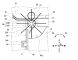
- FIG. 10 which is an enlarged view of FIG. 4 and the schematic perspective view of FIG. It is composed of two accumulation rollers 84, two tension rollers 85, and two impellers 86.
- the frame 2 is omitted in FIG. Further, in FIG. 11, the frame 2 and the upper conveyance guide 81 and the lower conveyance guide 82 are omitted.
- the lower surface of the upper conveyance guide 81 is formed in a curved shape along the conveyance path W (that is, the fourth conveyance path W4 or the fifth conveyance path W5), and the check CK advances along the conveyance path W by this lower surface. I will guide you.
- the upper conveyance guide 81 has its front end in proximity to or in contact with the rear end of the guide upper plate 61 in the conveyance ceiling guide 32.
- the lower conveyance guide 82 has an upper surface formed in a curved shape along the conveyance path W, and guides the check CK along the conveyance path W by the upper surface.
- the lower conveyance guide 82 has an extended curved portion 82E that extends downward and curves in the same arc shape as the peripheral side surface (described later) of the accumulation roller 84. Is provided.
- the upper conveyance guide 81 and the lower conveyance guide 82 are adapted to avoid interference with the stacking roller 84 and the like by appropriately forming holes and notches.
- the lower rotating shaft 83 is configured in an elongated cylindrical shape with the central axis extending in the left-right direction, and the accumulation roller 84 is inserted one by one in the vicinity of the right end and the center in the conveyance path W, One impeller 86 is inserted on each of the left and right outer sides.
- the lower rotating shaft 83 is rotated in the direction of the arrow R ⁇ b> 1, which is clockwise in the drawing, together with the accumulating roller 84 and the impeller 86 when a driving force is transmitted from a motor (not shown).
- the check CK is conveyed in the respective conveyance paths W in a state where the check CK is moved to the right side by the aligner unit 13. Accordingly, in the discharge unit 33, the two accumulation rollers 84 and the like are not arranged symmetrically in the conveyance path W, but are arranged in the vicinity of the right end and the vicinity of the center, respectively.
- the accumulating roller 84 is formed in a flat cylindrical shape with the central axis directed in the left-right direction, and the lower rotating shaft 83 is inserted through the central portion thereof.
- a high friction member is attached to the circumferential side surface of the accumulation roller 84 so that a high frictional force is applied to the check CK.
- the tension roller 85 is formed in a flat cylindrical shape with the central axis directed in the left-right direction, like the accumulation roller 84, and is disposed almost directly above each accumulation roller 84.
- the tension roller 85 can freely rotate around an upper rotation shaft provided on the upper side of the upper conveyance guide 81, and is urged downward by an urging member (not shown), that is, toward the accumulation roller 84. Yes.
- the combination of the accumulation roller 84 and the tension roller 85 is hereinafter also referred to as a discharge roller pair.
- the impeller 86 includes a central portion 86C attached to the lower rotary shaft 83 and a plurality of blade portions 86W provided radially along the radial direction from the outer peripheral portion of the central portion 86C to the outside. Yes.
- the central portion 86 ⁇ / b> C is formed in a flat cylindrical shape with the central axis directed in the left-right direction in the same manner as the accumulation roller 84.
- the blade portion 86W is formed into a long and narrow plate shape or a rod shape by a resin material that has flexibility and causes a frictional force to act on the check CK, and one end side thereof is fixed to the central portion 86C.
- the blade portion 86W rotates about the lower rotation shaft 83 as the center portion 86C rotates, and is appropriately deformed when it comes into contact with the check CK or the like, and causes a frictional force to act on the check CK. .
- the discharge unit 33 is configured so that the transport path from the rear lower transport unit 21 or the lower transport unit 23 (FIG. 3) in a state where the stacker 31 is loaded in the stacker loading space 30 as shown in FIGS.
- the lower rotating shaft 83 is rotated in the direction of the arrow R1.
- the accumulation roller 84 and the impeller 86 rotate in the direction of the arrow R1, and the tension roller 85 rotates in the direction of the arrow R2.
- the upper plate notches 61C1 and 61C2 (FIGS. 8 and 9) provided on the guide upper plate 61 of the transport ceiling guide 32 are formed so as to avoid the rotation trajectory of the blade portion 86W in the impeller 86. .
- the rear plate notches 44C1 and 44C2 (FIGS. 5 and 6) provided on the stacker rear side plate 44 of the stacker 31 also rotate the blade portion 86W in the impeller 86 when the stacker 31 is loaded at the loading position. It is formed so as to avoid the trajectory.
- the blade portion 86W of the impeller 86 passes through the upper plate cutout portions 61C1 and 61C2 of the transport ceiling guide 32, and passes through the rear plate cutout portions 44C1 and 44C2 of the stacker 31, while the guide upper plate 61 and the stacker rear portion. It can rotate smoothly without colliding with the side plate 44.
- the discharge unit 33 advances the check CK conveyed forward while continuing to guide the check CK along the conveyance path W by the upper conveyance guide 81 and the lower conveyance guide 82, and the check CK is fed to the stacking roller 84 and the tension roller 85. Hold between. Subsequently, the discharging unit 33 rotates the stacking roller 84 in the direction of the arrow R1 together with the lower rotating shaft 83 to transmit a backward force to the check CK to advance backward, and is loaded on the front lower side.
- the stacker 31 is discharged into the check storage space 31S.
- the rear side provided with the discharge portion 33 that discharges the check CK is also referred to as a discharge source side
- the front side in the opposite direction in which the released check CK travels is also referred to as a discharge destination side.
- the discharge portion 33 strikes the vicinity of the rear end of the released check CK downward by the blade portion 86W of the impeller 86, and draws it back to the lower side, that is, the stacker rear side plate 44 by the action of the frictional force. It is received by the rear side plate protrusion 44S formed between the portions 44C1 and 44C2 and dropped downward. As a result, the check CK is sequentially accumulated in the stacker 31 with the rear end in contact with or close to the stacker rear side plate 44.
- the stacker 31 is loaded into the stacker loading space 30, it is moved to the left side of the stacker loading space 30 by an operation of an operator or the like. 30. That is, the stacker 31 has a posture in which the stacker right side plate 42, the stacker left side plate 43, the stacker rear side plate 44, and the stacker front side plate 45 are directed in the right direction, left direction, rear direction, and front direction, respectively.
- the stacker 31 is loaded in the right direction with the position in the front-rear direction and the vertical direction with respect to the stacker loading space 30 determined.
- the rear movement guide unit 34 and the front movement guide unit 35 guide the relative positions of the stacker 31 in the vertical direction and the front-rear direction via the rear movement guide projection 48 and the front movement guide projection 49.
- the stacker 31 can be moved to the right while maintaining the height.
- the stacker 31 is provided with the right side plate notch portion 42C (FIGS. 5, 7, and 10) in the vicinity of the upper rear end of the stacker right side plate 42, so that the stacker right side plate 42 and the impeller 86 interfere with each other. It can be avoided.
- the stacker 31 includes a magnet 38 (FIG. 4) in which the metal plate 50 (FIGS. 6 and 7) attached to the metal plate attachment portion 46N of the right reinforcing portion 46 is provided in the stacker positioning portion 36 on the stacker loading space 30 side.
- the metal plate 50 is attracted to the magnet 38 and the position relative to the stacker loading space 30 is fixed.
- the position of the stacker 31 shown by a broken line in FIG. 4 in the stacker loading space 30 at this time is also referred to as a loading position.
- the stacker left side fitting portion 53 and the guide left side fitting portion 73 are fitted to each other at the left side portion.
- the stacker right side fitting portion 52 and the guide right side fitting portion 72 are fitted to each other at the right side portion.
- the upper end portion of the protruding portion 54 of the stacker left-side fitting portion 53 is positioned below the bottom portion of the recess 75 in the guide left-side fitting portion 73, that is, below the lower surface of the left bent portion 67. A gap is formed between them.
- the lower end portion of the protruding portion 74 in the guide left side fitting portion 73 is located above the bottom portion of the concave portion 55 in the stacker left side fitting portion 53, and a gap is formed between the lower portion and the concave portion 55.
- the upper end part of the protrusion part 54 in the stacker left side fitting part 53 has reached the upper side rather than the lower end part of the protrusion part 74 in the guide left side fitting part 73.
- a gap formed between the stacker left fitting portion 53 and the guide left fitting portion 73 (hereinafter referred to as the left fitting gap GL) is generally front and rear. Although it is along the direction, in detail, it is formed in a shape that is alternately bent in the vertical direction, that is, in a crank shape.
- the left fitting gap GL is formed so that the substantially horizontal portion along the front-rear direction is relatively short, and is sufficiently shorter than the short side of the check CK.
- the protruding portions 54 of the stacker right side fitting portion 52 are fitted to the right side of the guide as in the left side portion.
- the protrusions 74 of the guide right-side fitting part 72 are caused to enter the respective recesses 55 of the stacker right-side fitting part 52, as well as entering the respective recesses 75 of the part 72.
- a bent gap hereinafter referred to as a right fitting gap GR is formed.
- each protrusion 74 is positioned to the left of the front end of each protrusion 54, and the rear end of each protrusion 54 is The protrusion 74 is positioned on the left side of the front end.
- the left end portion of the stacker 31 has the end portion on the discharge source side (the side close to the discharge portion 33) in each of the protrusion portions (protrusion portions 54 and 74) aligned in the front-rear direction. Further, it is positioned on the take-out direction side (left side) closer to the outside of the check storage space 31S than the end portion (front end) on the discharge destination side of the protruding portion adjacent to the discharge source side (rear side).
- the B1-B2 cross section in FIG. 14 is symmetrical to the left side portion (FIG. 15) in the right side portion of the stacker 31 loaded in the loading position.
- the rear end is positioned on the right side of the front end of each protrusion 54
- the rear end of each protrusion 54 is positioned on the right side of the front end of each protrusion 74.
- the discharge source side end portions (rear ends) of the respective protrusion portions (protrusion portions 54 and 74) aligned along the front-rear direction are also discharged in the right side portion of the stacker 31. It is located on the loading direction side (right side) that is closer to the outside of the check storage space 31S than the end portion on the discharge destination side (front side) in the protruding portion adjacent to the original side (rear side).
- the upper end of the stacker left side plate 43 is arranged at a higher position in the stacker 31 than the upper end of the stacker right side plate 42 (FIGS. 5 to 7).
- the lower end of the guide left side plate 63 is arranged at a higher position than the lower end of the guide right side plate 62 (FIGS. 8 and 9).
- the upper end of the stacker right side plate 42 that is, the upper end of the protruding portion 54 in the stacker right side fitting portion 52, and the lower end of the guide left side plate 63,
- the respective heights are set so as to be sufficiently lower than the lower end of the protruding portion 74 in the guide left fitting portion 73.
- the stacker 31 is moved leftward from the loading position, that is, moved out of the stacker loading space 30 in the removal direction and taken out to the outside.
- the stacker right side plate 42 can be smoothly taken out without being brought into contact with the lower end of the guide left side plate 63.
- the structure mainly for reinforcement such as the left reinforcing portion 47 is omitted from the stacker rear side plate 44 and the stacker front side plate 45, and the entire range connecting the stacker right side plate 42 and the stacker left side plate 43 is omitted.
- a rear movement guide protrusion 48 and a front movement guide protrusion 49 were respectively provided.
- the magnet 38 is attached to the right inner surface in the stacker loading space 30 (FIGS. 4 and 17), and the metal plate 50 is attached to the right reinforcing portion 46 provided on the right side of the stacker right side plate 42 in the stacker 31. Provided (FIGS. 6, 7 and 17).
- the stacker unit 22 utilizes the attractive force acting between the magnet 38 and the metal plate 50 when the stacker 31 is loaded to some extent close to the loading position in the stacker loading space 30.
- the stacker 31 can reach the loading position and can be held at the loading position.
- the rotating impeller 86 is rotated at the upper end of the stacker rear plate 44, and the like. It is possible to prevent the generation or breakage of abnormal noise due to contact with the surface.
- the stacker 31 is provided with a metal plate 50 on the right reinforcing portion 46 provided at the same height as the left reinforcing portion 47 that functions as a handle (FIGS. 6, 7, 17, and 18). For this reason, in the stacker unit 22, when the stacker 31 is taken out from the loading position in the stacker loading space 30, the height at which force is applied in the left direction by an operator or the like and the metal plate 50 is attracted by the magnet 38. It is possible to equalize the height that is present.
- the stacker unit 22 can align the left and right direction, which is the direction along the groove shape of the rear movement guide unit 34 and the front movement guide unit 35, with the left direction that acts on the stacker 31.
- the rear movement guide protrusion 48 and the front movement guide protrusion 49 can be smoothly slid in the movement guide part 34 and the front movement guide part 35.
- the posture change caused by the generation of the rotational moment in the stacker 31, which may occur when the heights of both are different, the collision of the stacker left side fitting portion 53 and the guide left side fitting portion 73 accompanying this posture change, etc. Can also be prevented.
- a magnet 38 having a magnetic force is provided on the stacker loading space 30 side, and a metal plate 50 having no magnetic force is provided on the stacker 31 side.
- the stacker unit 22 of the check processing device 1 moves the stacker right side fitting part 52 and the guide right side fitting part 72 at a relatively low position when the stacker 31 is loaded in the stacker loading space 30.
- the stacker left side fitting portion 53 and the guide left side fitting portion 73 are fitted at relatively high positions (FIGS. 13, 14, and 17). Since the stacker portion 22 forms the left fitting gap GL and the right fitting gap GR that are bent in a crank shape along the front-rear direction, the check CK can be held in the check storage space 31S.
- the stacker unit 22 prevents the checker CK from being caught between the left guide plate 63 and the right stacker plate 42 when the stacker 31 is taken out, and prevents the stacker 31 from being taken out from the stacker loading space 30. (FIG. 18).
- the rear movement guide protrusion 48 and the front movement guide protrusion 49 are inserted into the rear movement guide section 34 and the front movement guide section 35, respectively, so that the stacker 31 is stacked in the stacker loading space 30.
- the case of moving in the left-right direction while maintaining the height is described (FIGS. 4 to 7, FIG. 10 and FIG. 12).
- the embodiment of the present invention is not limited to this, and the height of the stacker 31 is changed in the stacker loading space 30 by providing or guiding the movement guide portions and the movement guide projections having various shapes. You may make it move.
- the upper end of the stacker right side plate 42 is higher than the lower end of the guide left side plate 63 in such a range that the distance between the guide left side plate 63 and the stacker right side plate 42 is not more than the length of the short side of the check CK. It only has to be located on the lower side.
- each protrusion 74 is provided to be inclined with respect to the front-rear direction in each of the guide right fitting portion 72 and the guide left fitting portion 73 (FIG. 8). 9, FIG. 15 and FIG. 16).
- the embodiment of the present invention is not limited to this.
- the long side of the protruding part 174 instead of the protruding part 74
- the chamfering process may be performed on the protruding portion 154 of the stacker left side fitting portion 153 and the rear right end portion of the protruding portion 174.
- the front end of the check CK can be prevented from being caught.
- the height at which the check CK is discharged by the discharge portion 33 is sufficiently lower than the height of the guide right fitting portion 72 and the guide left fitting portion 73, the long side of the protruding portion 74 is aligned in the front-rear direction. You may arrange them.
- the rear movement guide protrusion 48 and the front movement guide protrusion 49 are arranged at different heights, and accordingly, the rear movement guide part 34 and the front movement guide part 35 are also different from each other.
- the embodiment of the present invention is not limited to this.
- the rear movement guide protrusion 48 and the front movement guide protrusion 49 have different vertical lengths and front / rear direction lengths, and the rear movement guide protrusion 48 and the front movement guide protrusion 49 have different shapes.
- the stacker 31 may be loaded in the stacker loading space 30 in the correct orientation and posture.
- the rear movement guide protrusion 48 and the front movement guide protrusion 49 are provided at the same height, and accordingly The rear movement guide unit 34 and the front movement guide unit 35 may also be provided at the same height.
- the embodiment of the present invention is not limited to this.
- the right reinforcing portion 46 and the left reinforcing portion 47 may be provided in the middle or lower part of the stacker right side plate 42 and the stacker left side plate 43 in the vertical direction.
- the height of the right reinforcing portion 46 and the left reinforcing portion 47 may be different from each other.
- at least one of the right reinforcing portion 46 and the left reinforcing portion 47 may be omitted.
- the metal plate 50 may be attached to the right side surface of the stacker right side plate 42.
- a check CK that is provided with a rear plate protrusion 44S between the rear plate cutout portions 44C1 and 44C2 at the upper end portion of the stacker rear plate 44 in the stacker 31 and is drawn backward by the impeller 86.
- the case of receiving is described (FIGS. 5, 6 and 11).
- the embodiment of the present invention is not limited to this.
- the check CK can be received by the extended curved portion 82E (FIG. 10) formed on the lower conveyance guide 82 of the discharge portion 33, the rear plate protrusion 44S is provided.
- a wide range of notches may be formed such that the rear plate notches 44C1 and 44C2 are connected. You may do it.
- the embodiment of the present invention is not limited to this.
- a magnet may be provided on the stacker 31 side
- a metal plate may be provided on the stacker loading space 30 side
- magnets having opposite polarities may be provided respectively.
- you may utilize various mechanisms other than the combination of a magnet and a metal plate, such as a well-known engagement mechanism. In short, as long as a certain large external force is not applied, it is sufficient that the stacker 31 can be positioned and held at the loading position in the stacker loading space 30.
- the discharge unit 33 includes the upper conveyance guide 81, the lower conveyance guide 82, the lower rotation shaft 83, the two accumulation rollers 84, the two tension rollers 85, and the two impellers 86. The case where it does is described (FIGS. 10 and 11).
- the embodiment of the present invention is not limited to this, and the discharge unit 33 may have other various configurations. In short, it is sufficient that the check CK can be discharged in the forward direction.
- the frame 2 as the frame, the bundle unit 11 as the input unit, the scanner unit 15 and the control unit 3 as the deposit processing unit, the stacker 31 as the stacker, and the stacker loading space
- the check processing device 1 as a check processing device is configured by the stacker loading space 30, the transport ceiling guide 32 as a guide, and the discharge portion 33 as a discharge portion
- the stacker includes a stacker right side plate 42 as a stacker loading side plate, a stacker right side fitting portion 52 as a stacker loading side fitting portion, a stacker left side plate 43 as a stacker extraction side plate, and a stacker extraction side fitting portion. And a stacker left side fitting portion 53 as a stacker.
- the guide was comprised by the guide upper side board 61 as a guide main-body part, the guide right side fitting part 72 as a guide loading side fitting part, and the guide left side fitting part 73 as a guide extraction side fitting part.
- a check processing device is configured by a frame having various other configurations, a loading unit, a depositing processing unit, a stacker, a stacker loading space, a guide, and a discharging unit. You may do it.
- the stacker includes a stacker loading side plate having various other configurations, a stacker loading side fitting portion, a stacker extraction side plate, and a stacker extraction side fitting portion, and a guide body having various other configurations. You may comprise by a part, a guide loading side fitting part, and a guide extraction side fitting part.
- the embodiment of the present invention can also be used in a check processing apparatus that stores a check in which a necessary process is completed in a detachable stacker, for example, in a deposit process using a check.
Landscapes
- Physics & Mathematics (AREA)
- General Physics & Mathematics (AREA)
- Pile Receivers (AREA)
Abstract
小切手処理装置のスタッカ部は、スタッカ装填空間にスタッカが装填された場合に、スタッカ右側嵌合部及びガイド右側嵌合部を比較的低い位置で嵌合させると共に、スタッカ左側嵌合部及びガイド左側嵌合部を比較的高い位置で嵌合させる。スタッカ部では、前後方向に沿ってクランク状に屈曲された左嵌合隙間及び右嵌合隙間をそれぞれ形成するため、小切手を小切手収納空間内に留めることができる。これに加えてスタッカ部では、スタッカの取出時に、ガイド左側板及びスタッカ右側板の間に小切手が挟まることが無く、スタッカ装填空間内からスタッカを取り出し得なくなることも回避できる。
Description
本開示は小切手処理装置に関し、例えば小切手による入金処理を行う小切手処理装置に適用することができるものである。
従来、小切手処理装置においては、金融機関等において顧客との間で媒体としての小切手による入金取引を行うものが普及している。この小切手処理装置では、入金取引において行う入金処理として、例えば小切手の表面及び裏面を撮像して画像データを生成する処理や、処理済であることを表す文字等を印刷する処理等を行う。
また小切手処理装置は、この入金処理を完了した小切手をスタッカ部へ搬送させる。このスタッカ部としては、例えば内部に小切手を収納すると共に上面が開放されたスタッカを所定のスタッカ装填空間に装填させ、該スタッカの上側から小切手を放出するものが提案されている(例えば、特開2002-255393号公報(図1)(特許文献1)参照)。
この小切手処理装置では、スタッカ内に十分な枚数の小切手が収納されると、スタッカ装填空間からスタッカが取り出され、該スタッカ内に収納されていた小切手が取り出された上で、該スタッカが再びスタッカ装填空間に装填される。
ところで、かかる構成の小切手処理装置では、放出部から放出される小切手がスタッカ内で舞い上がってしまった場合等に、該スタッカの外部へ飛び出してしまい、正しく収納できない恐れがある。そこでスタッカ部では、例えばスタッカの上側を閉塞するガイドを設けることが考えられる。
しかしながらこのスタッカ部では、スタッカ装填空間に対してスタッカを装填させ又は取り出させるために、該スタッカと該ガイドとの間にある程度の隙間を形成する必要が生じる。すなわちスタッカ部では、仮にスタッカの上側にガイドを設けたとしても、該スタッカ及び該ガイドの隙間から小切手が外部へ飛び出してしまう恐れがある。
そこでスタッカ部では、スタッカ及びガイドの隙間部分に、互いに向けて突出する突出部を相補的に配置し、互いに噛み合わせるような形状とすることにより、隙間を形成しながら外部への小切手の飛び出しを防止することが考えられる。
しかしながら、このようなスタッカ部では、スタッカ内に多数の小切手が収納され、その上面がガイドの突出部下端よりも高い位置まで到達した場合、該スタッカをスタッカ装填空間から取り出そうとしたときに、収納された小切手がスタッカの奥側の突出部とガイドの手前側の突出部との間に挟まり、取り出せなくなってしまう、という問題があった。
本開示は以上の点を考慮してなされたもので、小切手を内部に確実に収納でき、且つスタッカ装填空間からスタッカを容易に取り出し得る小切手処理装置を提案しようとするものである。
かかる課題を解決するため本発明の一実施形態の小切手処理装置においては、フレームと、フレーム内に設けられ、小切手が投入される投入部と、小切手を収納する小切手収納空間を内部に有し、該小切手収納空間の上側を開放させたスタッカと、フレーム内に形成されスタッカが装填されるスタッカ装填空間と、スタッカ装填空間の内部に設けられ、スタッカがスタッカ装填空間に装填された場合に該スタッカの上側に位置するガイドと、スタッカ装填空間に装填されたスタッカの小切手収納空間内へ小切手を放出する放出部とを設け、スタッカには、小切手収納空間の一側面を閉塞し、フレームの外部からスタッカ装填空間内へ装填される装填方向側に位置するスタッカ装填側板と、スタッカ装填側板の上端部分に形成され、上方へ突出した突出部及び下方へ凹んだ凹部が、装填方向と交差する幅方向に沿って交互に配置されたスタッカ装填側嵌合部と、小切手収納空間の他側面を閉塞し、スタッカ装填空間内からフレームの外部へ取り出される取出方向側に位置し、その上端部分がスタッカ装填側板の上端部分よりも高く形成されたスタッカ取出側板と、スタッカ取出側板の上端部分に形成され、上方へ突出した突出部及び下方へ凹んだ凹部が幅方向に沿って交互に配置されたスタッカ取出側嵌合部とをさらに設け、ガイドには、スタッカがスタッカ装填空間に装填された場合に小切手収納空間の上側を覆うガイド本体部と、スタッカがスタッカ装填空間に装填された場合に、スタッカ装填側板の上側に位置し、離散的に配置され下方へ突出した複数の突出部をスタッカ装填側嵌合部の凹部に入り込ませて嵌合させるガイド装填側嵌合部と、スタッカがスタッカ装填空間に装填された場合に、スタッカ取出側板の上側に位置し、離散的に配置され下方へ突出した複数の突出部をスタッカ取出側嵌合部の凹部に入り込ませて嵌合させるガイド取出側嵌合部とをさらに設け、スタッカ装填側板におけるスタッカ装填側嵌合部の上端は、スタッカがスタッカ装填空間から取り出される場合に、ガイド取出側嵌合部の下端よりも下側を通過するようにした。
本発明の一実施形態は、スタッカがスタッカ装填空間に装填された場合に、該スタッカの装填方向側においてスタッカ装填側嵌合部及びガイド装填側嵌合部を互いに嵌合させると共に、該スタッカの取出方向側においてスタッカ取出側嵌合部及びガイド取出側嵌合部を互いに嵌合させることにより、小切手が装填方向側及び取出方向側から飛び出すことを抑制し小切手収納空間内に留めることができる。これに加えて本発明の一実施形態は、スタッカがスタッカ装填空間から引き出される場合に、スタッカ装填側嵌合部の上端がガイド取出側嵌合部の下端よりも下側を通過するため、両者の間に小切手が挟まれて該スタッカの引出を阻害することが無い。
本発明の一実施形態によれば、小切手を内部に確実に収納でき、且つスタッカ装填空間からスタッカを容易に取り出し得る小切手処理装置を実現できる。
以下、発明を実施するための形態(以下実施の形態とする)について、図面を用いて説明する。
[1.小切手処理装置の構成]
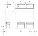
図1に模式的な斜視図を示すと共に図2に模式的な3面図を示すように、小切手処理装置1は、例えば金融機関等に設置されており、利用者(すなわち金融機関の顧客)との間で小切手の入金取引に関する処理を行う。この小切手処理装置1は、全体として直方体状に形成されたフレーム2の内部に、媒体としての小切手に関する種々の処理を行う複数の処理ユニットが組み込まれている。
図1に模式的な斜視図を示すと共に図2に模式的な3面図を示すように、小切手処理装置1は、例えば金融機関等に設置されており、利用者(すなわち金融機関の顧客)との間で小切手の入金取引に関する処理を行う。この小切手処理装置1は、全体として直方体状に形成されたフレーム2の内部に、媒体としての小切手に関する種々の処理を行う複数の処理ユニットが組み込まれている。
以下では、小切手処理装置1のうち顧客が対峙する側を前側とし、その反対を後側とし、当該前側に対峙した顧客から見て左及び右をそれぞれ左側及び右側とし、さらに上側及び下側を定義して説明する。
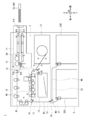
小切手処理装置1は、図3に模式的な左側面図を示すように、フレーム2の内部に組み込まれた制御部3が全体を統括的に制御している。この制御部3は、図示しないCPU(Central Processing Unit)を中心に構成されており、図示しないROM(Read Only Memory)やフラッシュメモリ等から所定のプログラムを読み出して実行することにより、入金取引に関する種々の処理を行う。また制御部3は、内部にRAM(Random Access Memory)、ハードディスクドライブやフラッシュメモリ等でなる記憶部を有しており、この記憶部に各種プログラムや入金取引に関する種々の情報を記憶させている。
因みに小切手処理装置1には、制御部3の制御に基づき利用者に向けて種々の情報を表示する表示部(図示せず)や、該利用者の操作指示を受け付けて該制御部3に通知する操作部(図示せず)等も設けられている。
フレーム2の上部における前側約半分の部分には、バンドル部11が配置されている。バンドル部11の前端には、開閉可能なシャッタ11Sが設けられている。制御部3は、上述した操作部(図示せず)を介して利用者から入金取引の開始を指示する操作を受け付けると、バンドル部11に対しシャッタ11Sを開放させるよう制御する。
これに応じてバンドル部11は、利用者に対し束状に集積された小切手CK(以下これを束小切手CKBとも呼ぶ)を内部に挿入させ、その後シャッタ11Sを閉塞することにより、内部に保有する小切手CKを保護する。因みに小切手CKは、長方形の紙により構成され、その表面に金額等の情報が表示されている。また束小切手CKBは、各小切手CKの長辺を前後に沿わせ、短辺を左右方向に沿わせると共に、金額等が記載された表面を上に向けた姿勢で挿入される。
バンドル部11は、内部に設けられた束搬送機構により前後方向に沿った束搬送路WBを形成しており、束小切手CKBをこの束搬送路WBに沿って後方向へ搬送し、該バンドル部11の後端近傍に設けられた分離部12の前側に到達させる。分離部12は、束小切手CKBの上面側から小切手CKを1枚ずつに分離し、後方のアライナ部13に順次引き渡していく。
アライナ部13は、主に前後方向に沿った搬送経路の後端に主に上下方向に沿った搬送経路の上端が接続された第1搬送路W1を内部に構成しており、分離部12から受け取った小切手CKをこの第1搬送路W1に沿って後方及び下方へ順次搬送する。このときアライナ部13は、該小切手CKを第1搬送路W1における幅方向の一方、例えば右側に寄せていき、下方に配置された第1切替部14に引き渡す。
第1切替部14は、制御部3の制御に基いて小切手CKの搬送経路を切り替えることにより、上側の第1搬送路W1及び後側の第2搬送路W2を接続し、或いは後側の第2搬送路W2及び下側の第3搬送路W3を接続するようになっている。すなわち第1切替部14は、アライナ部13から小切手CKが引き渡される場合、上側の第1搬送路W1及び後側の第2搬送路W2を接続し、この小切手CKを前方のスキャナ部15に引き渡す。
ところでアライナ部13及び第1切替部14の内部では、分離部12から受け取りスキャナ部15に引き渡すまでの小切手CKの搬送経路である第1搬送路W1を、英大文字の「C」のような形状、或いは英大文字の「U」の上側を前方へ向けて回転させたような形状に形成している。このため小切手CKは、表面を下側に向けた状態で、第1切替部14からスキャナ部15に引き渡される。
スキャナ部15は、アライナ部13のほぼ真下に位置しており、前後方向に沿った第2搬送路W2が内部に形成されている。このスキャナ部15は、第1切替部14から第2搬送路W2に沿って小切手CKを前方へ搬送しながら、該小切手CKからMICR文字を読み取り、また該小切手CKの両面をそれぞれ撮像して画像データを生成した上で、前下側に位置する第2切替部16に引き渡す。第2切替部16は、制御部3の制御により後上側及び前側を繋ぐように内部の搬送経路を切り替えており、スキャナ部15から受け取った小切手CKを前方のエスクロ部17に引き渡す。
エスクロ部17は、バンドル部11のほぼ真下に配置されており、その内部に回転するドラムや該ドラムの周側面に巻き付けるテープ、及び小切手CKを搬送するための搬送部等を有している。このエスクロ部17は、第2切替部16から受け取った小切手CKをドラムの周側面近傍へ搬送し、テープと共にドラムの周側面に順次巻き付けることにより、該小切手CKを一時的に保留していく。説明の都合上、ここまでの一連の処理を入金読取処理と呼ぶ。
制御部3は、バンドル部11に挿入された全ての小切手CKをスキャナ部15により読み取り終えると、読み取った内容を表す画像や文字等を表示部(図示せず)に表示すると共に、利用者に入金取引を継続するか否かを問い合わせる。
ここで利用者から入金取引の中止が指示されると、制御部3は、エスクロ部17に保留している全ての小切手CKを利用者に返却させる返却処理を開始する。すなわちエスクロ部17は、ドラムを逆回転させることにより保留していた小切手CKを1枚ずつ繰り出し、第2切替部16を介してスキャナ部15に引き渡していく。スキャナ部15、第1切替部14及びアライナ部13は、第2搬送路W2及び第1搬送路W1に沿って小切手CKを入金読取処理と反対方向へ搬送することにより、該小切手CKを分離部12に順次引き渡す。
分離部12は、引き渡された小切手CKを前方へ放出することにより、バンドル部11内に小切手CKを集積していく。バンドル部11は、分離部12により小切手CKが放出されて束小切手CKBが形成されると、シャッタ11Sを開放すると共に集積された小切手CKの束、すなわち束小切手CKBを束搬送路WBに沿って前方へ搬送し、その前側部分を外部に露出させた状態で挟持する。
ここでバンドル部11は、組み込まれたセンサにより束小切手CKBが取り出されたか否か監視している。制御部3は、バンドル部11のセンサにより束小切手CKBが取り出されたことを検出した場合、該束小切手CKBが利用者に返却されたものと判断し、シャッタ11Sを閉塞して返却処理を終了する。
一方、バンドル部11において所定時間内に束小切手CKBが取り出されなかった場合、制御部3は、利用者が束小切手CKBを取り忘れたまま立ち去ったと判断し、この束小切手CKBを取り込む取忘取込処理を開始する。具体的に制御部3は、入金読取処理の場合と同様、バンドル部11により束小切手CKBを後方へ搬送し、分離部12により再び1枚ずつの小切手CKに分離し、アライナ部13、第1切替部14及びスキャナ部15により第1搬送路W1及び第2搬送路W2に沿って第2切替部16まで搬送させる。
このとき第2切替部16は、制御部3の制御により後上側及び後下側を繋ぐように内部の搬送経路を切り替えており、スキャナ部15から受け取った小切手CKを後下方のリトラクト部18に引き渡す。リトラクト部18は、スキャナ部15のほぼ真下に配置されており、内部に小切手CKを収納する収納空間を形成すると共に、小切手CKをこの収納空間へ放出する放出機構を有している。このリトラクト部18は、第2切替部16から受け取った小切手CKを放出機構により放出空間内へ順次放出し、該小切手CKを該放出空間内に集積させた状態で収納する。これにより制御部3は、取忘取込処理を終了する。
一方、制御部3は、入金読取処理によってエスクロ部17に全ての小切手CKを保留した状態で、利用者から入金取引の継続が指示されると、保留している小切手CKを収納する収納処理を開始する。具体的にエスクロ部17は、ドラムを逆回転させることにより保留していた小切手CKを1枚ずつ繰り出し、第2切替部16を介してスキャナ部15に引き渡していく。
スキャナ部15は、第2切替部16から順次受け取った小切手CKを第2搬送路W2に沿って後方へ搬送しながら、内蔵するプリンタやスタンプ押印部により該小切手CKに対し取引結果等を表す情報を印字すると共にその画像を撮像して印字状態を認識した上で、該小切手CKを第1切替部14に引き渡す。
このとき第1切替部14は、制御部3の制御により前側の第2搬送路W2及び下側の第3搬送路W3を繋ぐように内部の搬送経路を切り替えており、スキャナ部15から受け取った小切手CKを下方の後中搬送部19に引き渡す。後中搬送部19は、リトラクト部18の後側において上下方向に沿って第3搬送路W3を形成されており、第1切替部14から受け取った小切手CKをこの第3搬送路W3に沿って下方へ搬送し、下側の第3切替部20に引き渡す。
第3切替部20は、制御部3の制御に基づいて内部の搬送経路を切り替えることにより、上側の第3搬送路W3及び下側の第4搬送路W4を繋ぎ、或いは上側の第3搬送路W3及び後側の第5搬送路W5を繋ぐようになっている。例えば第3切替部20は、上側の第3搬送路W3及び下側の第4搬送路W4を繋ぐように内部の搬送経路を切り替えていた場合、上側の後中搬送部19から受け取った小切手CKを、下側の後下搬送部21に引き渡す。
後下搬送部21は、上側と前下側とを結ぶように第4搬送路W4を形成しており、第3切替部20から受け取った小切手CKを前下方へ搬送し、その前下方に設けられた第1スタッカ部22Aに引き渡す。第1スタッカ部22Aは、フレーム2に対し着脱可能であり内部に多数の小切手CKを集積した状態で収納可能なスタッカや、該スタッカ内へ小切手CKを放出する放出機構等を有している。この第1スタッカ部22Aは、後下搬送部21から小切手CKを受け取ると、該小切手CKを放出機構により放出し、スタッカ内に集積した状態で収納する。
また第3切替部20は、上側の第3搬送路W3及び後側の第5搬送路W5を繋ぐように内部の搬送経路を切り替えていた場合、後中搬送部19から受け取った小切手CKを前側の下搬送部23に引き渡す。下搬送部23は、リトラクト部18の下側且つ第1スタッカ部22Aの上側において、後側と前下側とを結ぶように第5搬送路W5を形成しており、この第5搬送路W5に沿って小切手CKを前下方へ搬送し、その前下方に設けられた第2スタッカ部22Bに引き渡す。第2スタッカ部22Bは、第1スタッカ部22Aと同様に構成されており、下搬送部23から小切手CKを受け取ると、該小切手CKを放出機構により放出し、スタッカ内に集積して収納する。
かくして制御部3は、エスクロ部17に保留していた全ての小切手CKを第1スタッカ部22A又は第2スタッカ部22Bのスタッカ内に収納させると、収納処理を終了する。これにより制御部3は、利用者との間における小切手CKの入金取引を完了する。
[2.スタッカ部の構成]
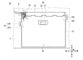
次に、第1スタッカ部22A及び第2スタッカ部22B(以下、両者をまとめてスタッカ部22と呼ぶ)の構成について説明する。スタッカ部22は、図2の一部を拡大した図4に示すように、主にフレーム2の内部に形成されたスタッカ装填空間30と、該スタッカ装填空間30の内部に装填され内部に小切手を収納するスタッカ31と、装填された該スタッカ31の上側に位置する搬送天井ガイド32と、小切手を放出する放出部33とにより構成されている。
次に、第1スタッカ部22A及び第2スタッカ部22B(以下、両者をまとめてスタッカ部22と呼ぶ)の構成について説明する。スタッカ部22は、図2の一部を拡大した図4に示すように、主にフレーム2の内部に形成されたスタッカ装填空間30と、該スタッカ装填空間30の内部に装填され内部に小切手を収納するスタッカ31と、装填された該スタッカ31の上側に位置する搬送天井ガイド32と、小切手を放出する放出部33とにより構成されている。
スタッカ装填空間30は、概ね直方体状の空間であり、左側面が開放されている。このためスタッカ31は、スタッカ装填空間30に対し左側から右方向へ移動されることにより該スタッカ装填空間30に装填される。またスタッカ31は、該スタッカ装填空間30内に装填された状態から左方向へ移動されることにより、該スタッカ装填空間30内から外部へ取り出される。説明の都合上、以下では、右方向及び左方向をそれぞれ装填方向及び取出方向とも呼ぶ。また、水平面内でこの装填方向及び取出方向と交差する方向である前後方向を幅方向とも呼ぶ。
またスタッカ装填空間30の後側及び前側には、後移動案内部34及び前移動案内部35がそれぞれ設けられている。第1移動ガイドとしての後移動案内部34は、左右方向に沿った中空の四角柱から前側面を省略したような形状でなる後移動案内部材34Cと、フレーム2の一部が該後移動案内部材34Cと対応する形状に切り欠かれた後切欠部2CRとにより構成され、後方向へ凹んだ溝状となっている。
第2移動ガイドとしての前移動案内部35は、後移動案内部34と概ね前後対称であり、後移動案内部材34Cと前後対称な前移動案内部材35Cと、フレーム2の一部が前移動案内部材35Cと対応する形状に切り欠かれた前切欠部2CFとにより構成され、前方向へ凹んだ溝状となっている。ただし前移動案内部35は、後移動案内部34よりも上側に配置されている。
また、スタッカ装填空間30の右内側面における前後方向のほぼ中央には、上下方向の中央よりもやや上側に、スタッカ位置決め部36が設けられている。スタッカ位置決め部36は、フレーム2における右内側面から左方向へやや突出するように設けられた位置決め台座部37と、該位置決め台座部37の左側面に設けられた磁石38とにより構成されている。
[2-1.スタッカの構成]
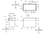
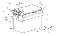
スタッカ31は、図5、図6及び図7に示すように、全体として中空の直方体状に形成されると共にその上面が開放されており、その内部に小切手を収納するための小切手収納空間31Sが形成されている。因みに図5は斜視図を表しており、図6は平面図並びに左側面図及び後側面図を表しており、図7は右側面図を表している。
スタッカ31は、図5、図6及び図7に示すように、全体として中空の直方体状に形成されると共にその上面が開放されており、その内部に小切手を収納するための小切手収納空間31Sが形成されている。因みに図5は斜視図を表しており、図6は平面図並びに左側面図及び後側面図を表しており、図7は右側面図を表している。
このスタッカ31は、小切手収納空間31Sの下側、右側、左側、後側及び前側に、それぞれ薄板状でなるスタッカ下側板41、スタッカ右側板42、スタッカ左側板43、スタッカ後側板44及びスタッカ前側板45が配置されている。因みにスタッカ31は、所定の樹脂材料が成型されることにより製造されている。すなわち小切手収納空間31Sは、下側面、右側面、左側面、後側面及び前側面が、スタッカ下側板41、スタッカ右側板42、スタッカ左側板43、スタッカ後側板44及びスタッカ前側板45によりそれぞれ閉塞されている。
スタッカ右側板42の右側面における上寄りの箇所には、右方向へ突出するようにして右補強部46が設けられている。右補強部46は、スタッカ右側板42と比較して前後方向の長さが同等であり上下方向の長さが1/4~1/5程度に短い直方体状でなり、その内部が中空に形成されると共に下面が開放されている。
また右補強部46(図7)の右側面における前後方向の中央付近には、金属板取付部46Nが設けられている。この金属板取付部46Nには、金属板50が取り付けられる。被位置決め部としての金属板50は、例えば鋼板のように磁性材料でなる金属により構成された、左右方向に薄い板状に形成されている。因みに、スタッカ装填空間30(図4)内に設けられたスタッカ位置決め部36における磁石38の高さは、スタッカ31が装填された場合における金属板50の高さと同等に揃えられている。
スタッカ左側板43の左側面における上寄りの箇所には、右補強部46とほぼ左右対称となる箇所、すなわち同等の高さとなる箇所に、該右補強部46とほぼ左右対称に構成された左補強部47が設けられている。ただし左補強部47には、金属板取付部46Nや金属板50が設けられていない。この左補強部47は、スタッカ31がスタッカ装填空間30内から左方向(すなわち取出方向)へ引き出される場合に、作業者の指先等を引っ掛けさせる「取手」として機能するようになっている。
スタッカ後側板44における上寄りであり、右補強部46及び左補強部47における下端とほぼ同等の高さとなる箇所には、該スタッカ後側板44の後側面から後方向へ突出するようにして、後移動案内突部48が設けられている。第1被ガイド体としての後移動案内突部48は、左右方向に細長い直方体状に構成されており、各稜線の近傍部分が斜めに切り落とされる、いわゆる面取り加工が適宜施されている。
後移動案内突部48の右端は、スタッカ右側板42よりも右側に位置する右補強部46の右側面と同等の位置に到達している。その一方で、後移動案内突部48の左端は、スタッカ左側板43と同等の位置に止まっており、左補強部47の左側面には到達していない。
後移動案内突部48における上下方向の長さは、スタッカ装填空間30(図4)に設けられた後移動案内部34における上下方向の長さ、すなわち溝幅よりも短くなっている。また、該スタッカ装填空間30における後移動案内部34の高さは、スタッカ31が装填される場合における後移動案内突部48の高さに合わせて設定されている。具体的には、スタッカ装填空間30の底板上面から後移動案内部34内の下内側面までの長さが、スタッカ31の下端から後移動案内突部48の下面までの長さよりも僅かに長くなっている。
スタッカ前側板45の前側には、その前側面から前方向へ突出するようにして、前移動案内突部49が設けられている。第2被ガイド体としての前移動案内突部49は、後移動案内突部48とほぼ前後対称に形成されているものの、該後移動案内突部48よりも上側に、具体的には右補強部46及び左補強部47における上端とほぼ同等の高さとなる箇所に設けられている。すなわちスタッカ31には、前後方向に関する両方の外側部分に、後移動案内突部48及び前移動案内突部49がそれぞれ設けられている。
前移動案内突部49における上下方向の長さは、後移動案内突部48の場合と同様、スタッカ装填空間30(図4)に設けられた前移動案内部35における上下方向の長さ、すなわち溝幅よりも短くなっている。また、該スタッカ装填空間30における前移動案内部35の高さは、スタッカ31が装填される場合における前移動案内突部49の高さに合わせて設定されている。具体的には、スタッカ装填空間30の底板上面から前移動案内部35内の下内側面までの長さが、スタッカ31の下端から前移動案内突部49の下面までの長さよりも僅かに長くなっている。
かかる構成に加えて、スタッカ右側板42及びスタッカ左側板43の上端近傍には、スタッカ右側嵌合部52及びスタッカ左側嵌合部53がそれぞれ形成されている。スタッカ左側嵌合部53には、上方へ向けて突出した突出部54と、この突出部54よりも下方へ凹んだ凹部55とが、前後方向に沿って交互に配置されている。
突出部54は、左右方向から見て、上端から下方へ進むに連れて前後方向の長さ、すなわち幅が長くなるような台形状に形成されている。これに応じて凹部55は、左右方向から見て、上辺よりも下辺の方が短い逆台形状の空間となっている。また各突出部54及び各凹部55における前後方向の長さは、何れも小切手CKの短辺よりも短くなっている。
スタッカ右側嵌合部52には、スタッカ左側嵌合部53と同様に、突出部54及び凹部55が前後方向に沿って交互に配置されている。またスタッカ右側嵌合部52は、スタッカ左側嵌合部53よりも低くなっている。さらにスタッカ右側板42における上後端近傍には、円弧状に切り欠かれた右側板切欠部42Cが形成されている。
またスタッカ後側板44の上端における右端近傍及び左右の中央近傍には、下方向へ向けて矩形状に切り欠かれた2箇所の後側板切欠部44C1及び44C2が形成されている。これに伴い、干渉回避部としての後側板切欠部44C1及び44C2の間には、切り欠かれずに残った部分が上方へ突出したような形状となった後側板突出部44Sが形成されている。この後側板突出部44Sの上端は、スタッカ後側板44の上端における左側部分と同等の高さに到達している。
このようにスタッカ31には、スタッカ右側板42及びスタッカ左側板43の上端部分に、前後方向に沿って複数の突出部54及び凹部55が整列されたスタッカ右側嵌合部52及びスタッカ左側嵌合部53が設けられている。またスタッカ31では、スタッカ右側嵌合部52よりもスタッカ左側嵌合部53の方が高い位置に配置されている。
[2-2.搬送天井ガイドの構成]
次に、搬送天井ガイド32(図4)の構成について説明する。搬送天井ガイド32は、スタッカ装填空間30内の上端近傍においてフレーム2に対し固定されており、スタッカ31が該スタッカ装填空間30に装填された場合に、小切手収納空間31Sの上側を覆うようにして、該スタッカ31のほぼ真上に位置する。
次に、搬送天井ガイド32(図4)の構成について説明する。搬送天井ガイド32は、スタッカ装填空間30内の上端近傍においてフレーム2に対し固定されており、スタッカ31が該スタッカ装填空間30に装填された場合に、小切手収納空間31Sの上側を覆うようにして、該スタッカ31のほぼ真上に位置する。
搬送天井ガイド32は、図8に斜視図を示すと共に図9に3面図を示すように、全体として前後方向に長く上下方向に薄い扁平な中空の直方体状に構成されている。この搬送天井ガイド32は、その上側、右側、左側及び前側に、それぞれ板状のガイド上側板61、ガイド右側板62、ガイド左側板63及びガイド前側板65が配置され、下側及び後側が開放されている。搬送天井ガイド32は、スタッカ31と比較して、左右方向の長さがほぼ同等であり、前後方向の長さが僅かに短くなっている。
ガイド上側板61は、その後端における右端近傍及び左右方向の中央付近に、前方へ向けて矩形状に切り欠かれた上側板切欠部61C1及び61C2が形成されている。ガイド右側板62は、前後方向に長く上下方向に短い板状に構成されており、その下端に右方向へ向けて屈曲されたような形状でなる右屈曲部66が設けられている。
ガイド左側板63は、ガイド右側板62と概ね左右対称に構成され、右屈曲部66と対応する左屈曲部67が形成されているものの、該ガイド右側板62よりも上下方向の長さが短くなっている。すなわちガイド左側板63の下端に設けられた左屈曲部67は、右屈曲部66よりも上側に位置している。因みに左屈曲部67における左右方向の長さは、右屈曲部66における左右方向の長さよりも短くなっている。
さらに、右屈曲部66及び左屈曲部67の下面には、スタッカ31側のスタッカ右側嵌合部52及びスタッカ左側嵌合部53(図5~図7)とそれぞれ対応するガイド右側嵌合部72及びガイド左側嵌合部73がそれぞれ設けられている。
ガイド右側嵌合部72には、下方へ向けて突出した複数の突出部74が前後方向に沿って離散的に配置されると共に、最も後側に後端突出部76が配置されている。突出部74は、前後方向に長く左右方向に薄い直方体状でなり、左右方向から見て上辺よりも下辺の方が短い台形状に形成されている。さらに突出部74は、下方向から見て、後側が右側に位置すると共に前側が左側に位置するように、すなわち後側よりも前側の方がガイド左側板63に近接するように、前後方向に対し傾斜されている。一方、後端突出部76は、前後方向に対し傾斜されておらず、前後方向に沿っている。
また突出部74同士の隙間は、左右方向から見ると、該突出部74よりも上方へ向けて凹んだ部分と見なすことができる。このため以下では、この隙間を凹部75と呼ぶ。すなわちガイド右側嵌合部72には、前後方向に沿って突出部74及び凹部75が交互に配置されていることになる。各突出部74及び各凹部75における前後方向の長さは、突出部54及び凹部55の場合と同様、何れも小切手CKの短辺よりも短くなっている。
ガイド左側嵌合部73は、ガイド右側嵌合部72と概ね左右対称に構成されている。すなわちガイド左側嵌合部73の突出部74は、下方向から見て、後側が左側に位置すると共に前側が右側に位置するように、すなわち後側よりも前側の方がガイド右側板62に近接するように、前後方向に対し傾斜されている。またガイド左側嵌合部73は、左屈曲部67が右屈曲部66よりも上側に位置しているために、ガイド右側嵌合部72よりも上側に位置している(図9)。
このように搬送天井ガイド32には、ガイド右側板62及びガイド左側板63の下端にそれぞれ形成された右屈曲部66及び左屈曲部67の下面に、前後方向に沿って複数の突出部74及び凹部75が整列されたガイド右側嵌合部72及びガイド左側嵌合部73が設けられている。また搬送天井ガイド32では、ガイド右側嵌合部72よりもガイド左側嵌合部73の方が高い位置に配置されている。
[2-3.放出部の構成]
図4の一部を拡大した図10に左側面図を示すと共に図11に模式的な斜視図を示すように、放出部33は、上搬送ガイド81、下搬送ガイド82、下回転軸83、2個の集積ローラ84、2個のテンションローラ85及び2個の羽根車86により構成されている。作図の都合上、図10では、フレーム2を省略している。また図11では、フレーム2並びに上搬送ガイド81及び下搬送ガイド82を省略している。
図4の一部を拡大した図10に左側面図を示すと共に図11に模式的な斜視図を示すように、放出部33は、上搬送ガイド81、下搬送ガイド82、下回転軸83、2個の集積ローラ84、2個のテンションローラ85及び2個の羽根車86により構成されている。作図の都合上、図10では、フレーム2を省略している。また図11では、フレーム2並びに上搬送ガイド81及び下搬送ガイド82を省略している。
上搬送ガイド81は、その下面が搬送路W(すなわち第4搬送路W4又は第5搬送路W5)に沿った曲面状に形成されており、この下面により小切手CKを搬送路Wに沿って進行させるよう案内する。また上搬送ガイド81は、その前端を搬送天井ガイド32におけるガイド上側板61の後端と近接若しくは当接させている。
下搬送ガイド82は、その上面が搬送路Wに沿った曲面状に形成されており、この上面により小切手CKを搬送路Wに沿って案内する。また下搬送ガイド82には、搬送路Wに沿って形成された部分に加えて、下方に延長されて集積ローラ84の周側面(後述する)と同様の円弧状に湾曲した延長湾曲部82Eが設けられている。因みに上搬送ガイド81及び下搬送ガイド82は、孔や切欠等が適宜形成されることにより、集積ローラ84等との干渉を回避するようになっている。
下回転軸83は、中心軸を左右方向に沿わせた細長い円柱状に構成されており、搬送路Wにおける右端近傍及び中央近傍となる箇所に集積ローラ84が1個ずつ挿通されると共に、その左右両外側に羽根車86が1個ずつ挿通されている。この下回転軸83は、図示しないモータから駆動力が伝達されることにより、集積ローラ84及び羽根車86と共に、図の時計回りである矢印R1方向へ回転する。
因みに小切手処理装置1(図1~図3)では、上述したように、小切手CKがアライナ部13により右側に寄せられた状態で、各搬送路W内を搬送される。これに応じて放出部33では、2個の集積ローラ84等が搬送路Wにおいて左右対称に配置されておらず、右端近傍及び中央近傍にそれぞれ配置されている。
集積ローラ84は、中心軸を左右方向に向けた扁平な円柱状に形成されており、下回転軸83がその中心部分に挿通されている。集積ローラ84の周側面には、高摩擦部材が取り付けられており、小切手CKとの間で高い摩擦力を作用させるようになっている。テンションローラ85は、集積ローラ84と同様に中心軸を左右方向に向けた扁平な円柱状に形成されており、各集積ローラ84のほぼ真上にそれぞれ配置されている。このテンションローラ85は、上搬送ガイド81の上側に設けられた上回転軸を中心として自在に回転し得ると共に、図示しない付勢部材により下方向へ、すなわち集積ローラ84に向けて付勢されている。説明の都合上、以下では集積ローラ84及びテンションローラ85の組み合わせを放出ローラ対とも呼ぶ。
羽根車86は、下回転軸83に取り付けられた中心部86Cと、該中心部86Cの外周部分から外方へ向かう放射方向に沿って放射状に設けられた複数の羽根部86Wとにより構成されている。中心部86Cは、集積ローラ84と同様に中心軸を左右方向に向けた扁平な円柱状に形成されている。羽根部86Wは、可撓性を有すると共に小切手CKに対し摩擦力を作用させるような樹脂材料により、細長い板状ないし棒状に構成され、その一端側が中心部86Cに固定されている。このため羽根部86Wは、中心部86Cの回転に伴って下回転軸83を中心に回転し、また小切手CK等に当接した場合に適宜変形すると共に、該小切手CKに対し摩擦力を作用させる。
かかる構成により放出部33は、図10及び図11に示したようにスタッカ装填空間30内にスタッカ31が装填された状態において、後下搬送部21又は下搬送部23(図3)から搬送路Wに沿って小切手CKが搬送されて来ると、下回転軸83を矢印R1方向へ回転させる。これにより放出部33では、集積ローラ84及び羽根車86が矢印R1方向へ回転すると共に、テンションローラ85が矢印R2方向へ回転する。
ここで搬送天井ガイド32のガイド上側板61に設けられた上側板切欠部61C1及び61C2(図8及び図9)は、羽根車86における羽根部86Wの回転軌跡を回避するように形成されている。またスタッカ31のスタッカ後側板44に設けられた後側板切欠部44C1及び44C2(図5及び図6)も、該スタッカ31が装填位置に装填された場合に、羽根車86における羽根部86Wの回転軌跡を回避するように形成されている。
このため羽根車86の羽根部86Wは、搬送天井ガイド32の上側板切欠部61C1及び61C2を通過すると共に、スタッカ31の後側板切欠部44C1及び44C2を通過しながら、ガイド上側板61及びスタッカ後側板44と衝突すること無く、円滑に回転することができる。
放出部33は、搬送されてきた小切手CKを上搬送ガイド81及び下搬送ガイド82により引き続き搬送路Wに沿って案内しながら前方向へ進行させ、該小切手CKを集積ローラ84及びテンションローラ85の間に挟持する。続いて放出部33は、下回転軸83と共に集積ローラ84を矢印R1方向へ回転させることにより、小切手CKに対し後方向へ向かう力を伝達して後方へ進行させ、その前下方に装填されているスタッカ31の内部へ、すなわち小切手収納空間31S内へ放出する。以下では、小切手CKを放出する放出部33が設けられた後側を放出元側とも呼び、その反対方向であり放出された小切手CKが進行する前側を放出先側とも呼ぶ。
さらに放出部33は、羽根車86の羽根部86Wにより、放出された小切手CKの後端付近を下方へ叩き付けると共に、摩擦力の作用により後下方へ、すなわちスタッカ後側板44へ引き寄せ、後側板切欠部44C1及び44C2の間に形成された後側板突出部44Sにより受け止めて、下方へ落下させる。この結果、スタッカ31内には、小切手CKが後端をスタッカ後側板44に当接または近接させた状態で、順次集積されていく。
[3.スタッカ装填空間に対するスタッカの装填及び取出]
次に、スタッカ部22におけるスタッカ装填空間30に対するスタッカ31の装填及び取出について説明する。スタッカ31は、スタッカ装填空間30に装填される場合、作業者等の操作により該スタッカ装填空間30の左側に移動され、前後方向の位置及び上下方向の位置並びにその向きや姿勢が該スタッカ装填空間30に概ね揃えられる。すなわちスタッカ31は、スタッカ右側板42、スタッカ左側板43、スタッカ後側板44及びスタッカ前側板45を、それぞれ右方向、左方向、後方向及び前方向へ向けた姿勢となる。
次に、スタッカ部22におけるスタッカ装填空間30に対するスタッカ31の装填及び取出について説明する。スタッカ31は、スタッカ装填空間30に装填される場合、作業者等の操作により該スタッカ装填空間30の左側に移動され、前後方向の位置及び上下方向の位置並びにその向きや姿勢が該スタッカ装填空間30に概ね揃えられる。すなわちスタッカ31は、スタッカ右側板42、スタッカ左側板43、スタッカ後側板44及びスタッカ前側板45を、それぞれ右方向、左方向、後方向及び前方向へ向けた姿勢となる。
スタッカ31は、この状態から右方向、すなわち装填方向へ移動されると、後移動案内突部48及び前移動案内突部49(図5~図7)をスタッカ装填空間30側の後移動案内部34及び前移動案内部35(図4)にそれぞれ入り込ませ、該スタッカ装填空間30内へ装填されていく。説明の都合上、以下ではスタッカ右側板42及びスタッカ右側嵌合部52をそれぞれスタッカ装填側板及びスタッカ装填側嵌合部とも呼び、またガイド右側嵌合部72をガイド装填側嵌合部とも呼ぶ。
このとき後移動案内突部48は、スタッカ31全体に重力が作用するため、図10に示したように、その下面を後移動案内部34における後移動案内部材34Cの下内側面に当接及び摺動させる。また前移動案内突部49は、やはりスタッカ31全体に重力が作用するため、図12に示すように、その下面を前移動案内部35における前移動案内部材35Cの下内側面に当接及び摺動させる。
これによりスタッカ31は、スタッカ装填空間30に対する前後方向及び上下方向の位置が定められた状態で、右方向へ装填されていく。換言すれば、後移動案内部34及び前移動案内部35は、後移動案内突部48及び前移動案内突部49を介して、スタッカ31の上下方向及び前後方向に関する相対的な位置を案内しながら、該スタッカ31の高さを維持したまま右方向へ移動させることができる。このときスタッカ31は、スタッカ右側板42における上後端近傍に右側板切欠部42C(図5、図7及び図10)が設けられているため、該スタッカ右側板42及び羽根車86の干渉を回避することができる。
やがてスタッカ31は、右補強部46の金属板取付部46Nに取り付けられた金属板50(図6及び図7)がスタッカ装填空間30側のスタッカ位置決め部36に設けられた磁石38(図4)に当接すると、該金属板50が該磁石38に吸着されることにより、該スタッカ装填空間30に対する位置が固定される。以下、このときのスタッカ装填空間30内におけるスタッカ31の位置(図4に破線で示す)を装填位置とも呼ぶ。
スタッカ部22では、このようにしてスタッカ31が装填位置に装填されると、図11に示したように、その左側部分においてスタッカ左側嵌合部53及びガイド左側嵌合部73を互いに嵌合させると共に、その右側部分においてスタッカ右側嵌合部52及びガイド右側嵌合部72を互いに嵌合させる。
具体的にスタッカ部22では、図13に示すように、スタッカ装填空間30内の左側部分において、スタッカ左側嵌合部53の各突出部54をガイド左側嵌合部73の各凹部75に入り込ませると共に、ガイド左側嵌合部73の各突出部74をスタッカ左側嵌合部53の各凹部55に入り込ませる。
このときスタッカ左側嵌合部53における突出部54の上端部分は、ガイド左側嵌合部73における凹部75の底部分、すなわち左屈曲部67の下面よりも下側に位置しており、該凹部75との間に隙間を形成している。これと同様に、ガイド左側嵌合部73における突出部74の下端部分は、スタッカ左側嵌合部53における凹部55の底部分よりも上側に位置しており、該凹部55との間に隙間を形成している。
スタッカ左側嵌合部53における突出部54の上端部分は、ガイド左側嵌合部73における突出部74の下端部分よりも上側に到達している。これによりスタッカ装填空間30内の左側部分では、スタッカ左側嵌合部53及びガイド左側嵌合部73の間に形成された隙間(以下これを左嵌合隙間GLと呼ぶ)が、全体としては前後方向に沿っているものの、詳細には上下方向へ交互に屈曲した形状に、すなわちクランク状に形成される。特に左嵌合隙間GLは、前後方向に沿った概ね水平な部分が、何れも比較的短く、小切手CKにおける短辺よりも十分に短く形成されている。
またスタッカ部22では、図13と対応する図14に示すように、スタッカ装填空間30内の右側部分においても、左側部分と同様、スタッカ右側嵌合部52の各突出部54をガイド右側嵌合部72の各凹部75に入り込ませると共に、ガイド右側嵌合部72の各突出部74をスタッカ右側嵌合部52の各凹部55に入り込ませる。このときスタッカ右側嵌合部52における突出部54及び凹部55と、ガイド右側嵌合部72における凹部75及び突出部74との間には、左側部分と同様に、前後方向に沿ってクランク状に屈曲した隙間(以下これを右嵌合隙間GRと呼ぶ)が形成される。
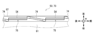
ところでガイド左側嵌合部73の各突出部74は、図8及び図9に示したように、後側が左側に位置すると共に前側が右側に位置するように長辺部分を前後方向に対し傾斜させた姿勢となっている。さらに突出部74は、図13におけるA1-A2断面を図15に示すように、スタッカ31が装填位置に装填された場合に、その後端部分をスタッカ左側嵌合部53の突出部54よりも左側に位置させると共に、その前端部分を該突出部54よりも右側に位置させる。
すなわちスタッカ部22では、装填位置に装填されたスタッカ31の左側部分において、各突出部74の後端を各突出部54の前端よりも左側に位置させ、また各突出部54の後端を各突出部74の前端よりも左側に位置させている。これを換言すると、スタッカ部22では、スタッカ31の左側部分において、前後方向に沿って並んだ各突出部(突出部54及び74)における放出元側(放出部33に近い側)の端部を、その放出元側(後側)に隣接する突出部における放出先側の端部(前端)よりも、小切手収納空間31Sの外側寄りとなる取出方向側(左側)に位置させている。
またスタッカ部22では、図14におけるB1-B2断面を図16に示すように、装填位置に装填されたスタッカ31の右側部分において、左側部分(図15)と左右対称に、各突出部74の後端を各突出部54の前端よりも右側に位置させ、また各突出部54の後端を各突出部74の前端よりも、右側に位置させている。これを換言すると、スタッカ部22では、スタッカ31の右側部分においても、前後方向に沿って並んだ各突出部(突出部54及び74)における放出元側の端部(後端)を、その放出元側(後側)に隣接する突出部における放出先側(前側)の端部よりも、小切手収納空間31Sの外側寄りとなる装填方向側(右側)に位置させている。
これに加えてスタッカ部22では、上述したように、スタッカ31においてスタッカ右側板42の上端よりもスタッカ左側板43の上端を高い位置に配置し(図5~図7)、且つ搬送天井ガイド32においてガイド右側板62の下端よりもガイド左側板63の下端を高い位置に配置した(図8及び図9)。
ここでスタッカ部22では、模式的な断面図を図17に示すように、スタッカ右側板42の上端、すなわちスタッカ右側嵌合部52における突出部54の上端を、ガイド左側板63の下端、すなわちガイド左側嵌合部73における突出部74の下端よりも十分に低くなるよう、それぞれの高さを設定している。
このためスタッカ部22では、図17と対応する図18に示すように、スタッカ31を装填位置から左方向へ移動させる場合、すなわちスタッカ装填空間30内から取出方向へ移動されて外部へ取り出される場合に、スタッカ右側板42の上端をガイド左側板63の下端に当接させることなく、円滑に取り出させることができる。
なお説明の都合上、以下ではスタッカ左側板43及びスタッカ左側嵌合部53をそれぞれスタッカ取出側板及びスタッカ取出側嵌合部とも呼び、またガイド左側嵌合部73をガイド取出側嵌合部とも呼ぶ。
[4.効果等]
以上の構成において、小切手処理装置1のスタッカ部22は、スタッカ31におけるスタッカ右側板42及びスタッカ左側板43の上端部分に、前後方向に沿って突出部54及び凹部55が交互に配置されたスタッカ右側嵌合部52及びスタッカ左側嵌合部53をそれぞれ設けた(図5~図7)。
以上の構成において、小切手処理装置1のスタッカ部22は、スタッカ31におけるスタッカ右側板42及びスタッカ左側板43の上端部分に、前後方向に沿って突出部54及び凹部55が交互に配置されたスタッカ右側嵌合部52及びスタッカ左側嵌合部53をそれぞれ設けた(図5~図7)。
またスタッカ部22は、搬送天井ガイド32におけるガイド右側板62の及びガイド左側板63の下端部分、すなわち右屈曲部66及び左屈曲部67の下面側に、前後方向に沿って突出部74及び凹部75が交互に配置されたガイド右側嵌合部72及びガイド左側嵌合部73をそれぞれ設けた(図8及び図9)。
スタッカ部22では、スタッカ装填空間30内の装填位置にスタッカ31が装填されると、搬送天井ガイド32の真下に該スタッカ31を位置させることになる(図4、図11)。このときスタッカ部22では、スタッカ31の左側部分において、スタッカ左側嵌合部53及びガイド左側嵌合部73を互いに嵌合させ、前後方向に沿ってクランク状に屈曲された左嵌合隙間GLを形成する(図13及び図14)。またスタッカ部22では、スタッカ31の右側部分において、スタッカ右側嵌合部52及びガイド右側嵌合部72を互いに嵌合させ、前後方向に沿ってクランク状に屈曲された右嵌合隙間GRを形成する(図15及び図16)。
スタッカ部22は、各突出部及び各凹部における前後方向の長さを小切手CKの短辺よりも短くしたことにより、左嵌合隙間GL及び右嵌合隙間GRにおける直線状に形成された各部分の長さが、該小切手CKの短辺よりも短くなっている。これによりスタッカ部22は、左嵌合隙間GL及び右嵌合隙間GRから小切手CKが飛び出して落下することを防止でき、該小切手CKをスタッカ31の小切手収納空間31S内に留めることができる。
これに加えてスタッカ部22では、スタッカ右側板42をガイド右側板62と直接接触させず、またスタッカ左側板43をガイド左側板63と直接接触させないため、スタッカ31の装填や取出の際に該搬送天井ガイド32と干渉することや摩擦を生じることが無く、干渉や衝突による破損を回避できる。
ここで、スタッカ部22において、小切手収納空間31S内に多数の小切手CKが収納され、最も上側の小切手CKがスタッカ右側板42の上端よりも上側に積み上がっている状態(以下これを過集積状態と呼ぶ)を想定する。また、仮想的なスタッカ部として、スタッカ31におけるスタッカ右側板42の上端及びスタッカ左側板43の上端が同等の高さであり、搬送天井ガイド32においてガイド右側板62の下端及びガイド左側板63の下端も同等の高さであったとする。
この仮想的なスタッカ部が過集積状態であり、スタッカ31を左方向へ引き出す場合、最も上側に位置する小切手CKの左辺がガイド左側板63に当接し、且つその右辺がスタッカ右側板42に当接することがある。このような場合、この仮想的なスタッカ部では、ガイド左側板63及びスタッカ右側板42の間に小切手CKが挟まり、該小切手CKがストッパとして機能することにより、スタッカ31を取り出し得なくなる恐れがあった。
この点において、本実施の形態によるスタッカ部22では、スタッカ31のスタッカ右側板42の上端よりもスタッカ左側板43の上端を高い位置に配置し、且つ搬送天井ガイド32においてガイド右側板62の下端よりもガイド左側板63の下端を高い位置に配置した(図17)。これによりスタッカ部22では、ガイド左側板63及びスタッカ右側板42の間に小切手CKが挟まることが無く、スタッカ装填空間30内からスタッカ31を取り出し得なくなることも回避できる(図18)。
またスタッカ部22では、装填位置に装填されたスタッカ31の左側部分において、ガイド左側嵌合部73における各突出部74の後端部分(放出元側の端部)をスタッカ左側嵌合部53の突出部54よりも左側に位置させると共に、その前端部分(放出先側の端部)を該突出部54よりも右側に位置させるようにした(図15)。これと同様にスタッカ部22では、該スタッカ31の右側部分において、ガイド右側嵌合部72における各突出部74の後端部分(放出元側の端部)をスタッカ右側嵌合部52の突出部54よりも右側に位置させると共に、その前端部分(放出先側の端部)を該突出部54よりも左側に位置させるようにした(図16)。
これによりスタッカ部22では、放出部33から放出された小切手CKが小切手収納空間31S内を前方へ、すなわち放出元側から放出先側へ進行する場合に、該小切手CKの前端における左右の頂点部分等を、各突出部における放出元側の端部(後端部分)に引っ掛かけさせることなく、円滑に進行させることができる。
さらにスタッカ部22では、図10に示したように、装填位置に装填されたスタッカ31におけるスタッカ後側板44の上端を、放出部33の下搬送ガイド82における延長湾曲部82Eの下端よりも後側且つ上側に位置させた。これによりスタッカ部22では、スタッカ後側板44及び延長湾曲部82Eの接触による摩擦の発生や破損を防止しながら、小切手収納空間31S内の小切手CKがスタッカ後側板44及び延長湾曲部82Eの隙間から後方へ飛び出る(落下する)ことを防止できる。
これと同様にスタッカ部22では、図12に示したように、装填位置に装填されたスタッカ31におけるスタッカ前側板45の上端を、搬送天井ガイド32におけるガイド前側板65の下端よりも、前側且つ上側に位置させた。これによりスタッカ部22では、スタッカ前側板45及びガイド前側板65の接触による摩擦の発生や破損を防止しながら、小切手収納空間31S内の小切手CKがスタッカ前側板45及びガイド前側板65の隙間から前方へ飛び出る(落下する)ことを防止できる。
またスタッカ部22では、スタッカ装填空間30側の後側及び前側において、高さが互いに異なる箇所に、後移動案内部34及び前移動案内部35をそれぞれ設けると共に(図4)、スタッカ31の後側及び前側において、高さが互いに異なる箇所に、後移動案内突部48及び前移動案内突部49をそれぞれ設けた(図5~図7)。
このためスタッカ部22では、仮にスタッカ装填空間30に対しスタッカ31を誤った向きに、すなわちスタッカ右側板42を左側に向けた姿勢で装填されようとした場合に、後移動案内突部48が前移動案内部35に入らず、また前移動案内突部49も後移動案内部34に入らないため、誤った向きや姿勢での装填を未然に防止できる。
またスタッカ部22では、スタッカ装填空間30において後移動案内部34及び前移動案内部35の高さが互いに相違すること、及び後移動案内突部48及び前移動案内突部49の高さが互いに相違することを作業者等が容易に目視確認できるため、正しい向きや姿勢を容易に把握させることができる。
さらにスタッカ部22では、スタッカ31における比較的上側に後移動案内突部48及び前移動案内突部49をそれぞれ設け(図5~図7)、これらの下面を後移動案内部34及び前移動案内部35における下内側面に当接させることにより、スタッカ装填空間30内における該スタッカ31の高さを定めるようにした(図11及び図12)。
このためスタッカ部22は、スタッカ31における比較的下側にこれらを設ける場合や、これらを省略してスタッカ下側板41により高さを合わせる場合と比較して、スタッカ右側板42及びスタッカ左側板43の上端から近い箇所において、スタッカ装填空間30に対する該スタッカ31の上下方向に関する位置を定めることができる。これによりスタッカ部22は、スタッカ31におけるスタッカ右側嵌合部52及びスタッカ左側嵌合部53と、搬送天井ガイド32におけるガイド右側嵌合部72及びガイド左側嵌合部73との間隔を、設計上の値に精度良く合わせること、すなわち右嵌合隙間GR及び左嵌合隙間GLを適切に形成することができる。
さらにスタッカ31では、スタッカ後側板44及びスタッカ前側板45に対し、左補強部47のような補強を主目的とした構造を省略する一方、スタッカ右側板42及びスタッカ左側板43を結ぶ全範囲に渡って、後移動案内突部48及び前移動案内突部49をそれぞれ設けた。これによりスタッカ部22では、スタッカ31において、後移動案内突部48及び前移動案内突部49を、位置決め用の部材として機能させることに加えて、スタッカ後側板44及びスタッカ前側板45におけるそれぞれの上端近傍を補強する補強部材としても機能させることができる。
またスタッカ部22では、スタッカ装填空間30内における右内側面に磁石38を取り付けると共に(図4及び図17)、スタッカ31におけるスタッカ右側板42の右側に設けた右補強部46に金属板50を設けた(図6、図7及び図17)。このためスタッカ部22は、スタッカ31の装填時に、該スタッカ31をスタッカ装填空間30内における装填位置にある程度近接させた時点で、磁石38及び金属板50の間に作用する吸引力を利用して、該スタッカ31を装填位置に到達させるとともに、該装填位置に保持することができる。
これによりスタッカ部22では、例えば作業者等が目視では気付かない程度にスタッカ31が装填位置から左側にずれて装填された場合に生じ得る、回転する羽根車86がスタッカ後側板44の上端部等に当接することによる異音の発生や破損等を未然に防止できる。
さらにスタッカ31は、取手として機能する左補強部47と同等の高さに設けられた右補強部46に金属板50を設けた(図6、図7、図17及び図18)。このためスタッカ部22では、スタッカ装填空間30内の装填位置からスタッカ31が取り出される場合に、作業者等によって左方向へ向けて力が加えられる高さと、磁石38により金属板50を吸着している高さとを同等に揃えることができる。
これによりスタッカ部22では、後移動案内部34及び前移動案内部35における溝形状が沿った方向である左右方向と、スタッカ31に作用する方向である左方向とを揃えることができ、該後移動案内部34及び前移動案内部35内で後移動案内突部48及び前移動案内突部49を円滑に摺動させることができる。またスタッカ部22では、双方の高さが異なる場合に生じ得る、スタッカ31における回転モーメントの発生による姿勢変化や、この姿勢変化に伴うスタッカ左側嵌合部53及びガイド左側嵌合部73の衝突等を未然に防止することもできる。
これに加えてスタッカ部22では、スタッカ装填空間30側に磁力を有する磁石38を設けると共に、スタッカ31側に磁力を有さない金属板50を設けた。これによりスタッカ部22では、例えばスタッカ31がスタッカ装填空間30から取り出されて移動される場合や様々な場所に設置された場合等に、磁気記録がなされた媒体等が金属板50に近接若しくは当接されたとしても、その記録内容に影響を及ぼすことが無い。
以上の構成によれば、小切手処理装置1のスタッカ部22は、スタッカ装填空間30にスタッカ31が装填された場合に、スタッカ右側嵌合部52及びガイド右側嵌合部72を比較的低い位置で嵌合させると共に、スタッカ左側嵌合部53及びガイド左側嵌合部73を比較的高い位置で嵌合させる(図13、図14及び図17)。スタッカ部22では、前後方向に沿ってクランク状に屈曲された左嵌合隙間GL及び右嵌合隙間GRをそれぞれ形成するため、小切手CKを小切手収納空間31S内に留めることができる。これに加えてスタッカ部22では、スタッカ31の取出時に、ガイド左側板63及びスタッカ右側板42の間に小切手CKが挟まることが無く、スタッカ装填空間30内からスタッカ31を取り出し得なくなることも回避できる(図18)。
[5.他の実施の形態]
なお上述した実施の形態においては、後移動案内部34及び前移動案内部35内に後移動案内突部48及び前移動案内突部49をそれぞれ入り込ませることにより、スタッカ装填空間30内でスタッカ31の高さを維持したまま左右方向へ移動させる場合について述べた(図4~図7、図10及び図12)。しかしながら本発明の実施形態はこれに限らず、種々の形状の移動案内部及び移動案内突部を設け、或いはこれらを省略することにより、スタッカ装填空間30内でスタッカ31の高さを変化させながら移動させるようにしても良い。この場合、少なくとも左右方向に関しガイド左側板63及びスタッカ右側板42の間隔が小切手CKにおける短辺の長さ以下となる範囲において、該スタッカ右側板42の上端が該ガイド左側板63の下端よりも下側に位置していれば良い。
なお上述した実施の形態においては、後移動案内部34及び前移動案内部35内に後移動案内突部48及び前移動案内突部49をそれぞれ入り込ませることにより、スタッカ装填空間30内でスタッカ31の高さを維持したまま左右方向へ移動させる場合について述べた(図4~図7、図10及び図12)。しかしながら本発明の実施形態はこれに限らず、種々の形状の移動案内部及び移動案内突部を設け、或いはこれらを省略することにより、スタッカ装填空間30内でスタッカ31の高さを変化させながら移動させるようにしても良い。この場合、少なくとも左右方向に関しガイド左側板63及びスタッカ右側板42の間隔が小切手CKにおける短辺の長さ以下となる範囲において、該スタッカ右側板42の上端が該ガイド左側板63の下端よりも下側に位置していれば良い。
また上述した実施の形態においては、ガイド右側嵌合部72及びガイド左側嵌合部73それぞれにおいて、各突出部74の長辺を前後方向に対して傾斜させるように設ける場合について述べた(図8、図9、図15及び図16)。しかしながら本発明の実施形態はこれに限らず、例えば図19に示すように、ガイド左側嵌合部73に代わるガイド左側嵌合部173において、突出部74に代わる突出部174の長辺を前後方向に対し傾斜させずに配置し、且つスタッカ左側嵌合部153の突出部154及び該突出部174の後右端部分に面取り加工をそれぞれ施すようにしても良い。この場合も、小切手CKの前端が引っ掛かることを防止できる。或いは、例えば放出部33により小切手CKが放出される高さがガイド右側嵌合部72及びガイド左側嵌合部73の高さよりも十分に低い場合に、突出部74の長辺を前後方向に沿わせて配置しても良い。
さらに上述した実施の形態においては、後移動案内突部48及び前移動案内突部49を互いに異なる高さに配置し、これに応じて後移動案内部34及び前移動案内部35も互いに異なる高さに配置することにより、スタッカ装填空間30に対しスタッカ31を正しい向きや姿勢で装填させる場合について述べた。しかしながら本発明の実施形態はこれに限らず、例えば後移動案内突部48及び前移動案内突部49における上下方向の長さや前後方向の長さを互いに相違させ、それぞれと対応する形状に後移動案内部34及び前移動案内部35をそれぞれ形成することにより、スタッカ装填空間30に対しスタッカ31を正しい向きや姿勢で装填させるようにしても良い。或いは、例えばスタッカ装填空間30に対するスタッカ31の姿勢や向きを規制する部材を別途設ける場合等に、後移動案内突部48及び前移動案内突部49を互いに同等の高さに設け、これに応じて後移動案内部34及び前移動案内部35も互いに同等の高さに設けるようにしても良い。
さらに上述した実施の形態においては、後移動案内突部48及び前移動案内突部49を、スタッカ右側板42及びスタッカ左側板43結ぶ全範囲に渡る左右方向に長い直方体状とすることにより、スタッカ後側板44及びスタッカ前側板45を補強する場合について述べた。しかしながら本発明の実施形態はこれに限らず、例えばスタッカ後側板44及びスタッカ前側板45の強度が十分である場合や、他に補強部材を設ける場合等に、左右方向に短い複数の立体形状を離散的に複数配置する等、種々の形状でなる後移動案内突部48及び前移動案内突部49を構成しても良い。さらには、例えばスタッカ31のスタッカ下側板41によりスタッカ装填空間30内における高さ方向の位置を定める場合等に、後移動案内突部48及び前移動案内突部49並びに後移動案内部34及び前移動案内部35を省略しても良い。
さらに上述した実施の形態においては、スタッカ右側板42及びスタッカ左側板43における比較的上寄りの箇所に右補強部46及び左補強部47をそれぞれ設ける場合について述べた。しかしながら本発明の実施形態はこれに限らず、例えばスタッカ右側板42及びスタッカ左側板43における上下方向の中程や下寄りとなる箇所に右補強部46及び左補強部47をそれぞれ設けても良く、また右補強部46及び左補強部47の高さを互いに相違させても良い。或いは、右補強部46及び左補強部47の少なくとも一方を省略しても良い。特に右補強部46を省略する場合、スタッカ右側板42の右側面に金属板50を取り付ければ良い。
さらに上述した実施の形態においては、スタッカ31におけるスタッカ後側板44の上端部分において、後側板切欠部44C1及び44C2の間に後側板突出部44Sを設け、羽根車86により後方へ引き寄せられた小切手CKを受け止める場合について述べた(図5、図6及び図11)。しかしながら本発明の実施形態はこれに限らず、例えば放出部33の下搬送ガイド82に形成された延長湾曲部82E(図10)により小切手CKを受け止めることができる場合に、後側板突出部44Sを省略し、後側板切欠部44C1及び44C2を連結させたような広範囲の切欠部を形成しても良い。
しても良い。
しても良い。
さらに上述した実施の形態においては、スタッカ31の右補強部46に金属板50を設けると共に、スタッカ装填空間30内のスタッカ位置決め部36に磁石38を設ける場合について述べた(図4、図6、図7及び図17)。しかしながら本発明の実施形態はこれに限らず、例えばスタッカ31側に磁石を設けると共に、スタッカ装填空間30側に金属板を設けても良く、或いは互いに逆の極性の磁石をそれぞれに設けても良い。また、例えば周知の係合機構等、磁石及び金属板の組合せ以外の種々の機構を利用しても良い。要は、ある程度大きな外力が加えられない限り、スタッカ31をスタッカ装填空間30内の装填位置に位置決めし、且つ保持できれば良い。
さらに上述した実施の形態においては、スタッカ部22に金属板50及び磁石38の組合せを1組のみ設ける場合について述べた。しかしながら本発明の実施形態はこれに限らず、スタッカ部22に金属板50及び磁石38の組合せを2組以上設けても良い。この場合、金属板50及び磁石38の組合せを前後方向や上下方向に引き離して配置することにより、装填位置におけるスタッカ31の姿勢をより安定させることができる。さらには、例えばスタッカ装填空間30の右内側面における1以上の箇所に、スタッカ31が装填位置に装填された場合にスタッカ右側板42や右補強部46等に当接してその姿勢を保持させる当接保持部材を適宜設けても良い。
さらに上述した実施の形態においては、スタッカ装填空間30の左側を開放し、この開放された部分を介してスタッカ31の装填及び取出を行わせる場合について述べた。しかしながら本発明の実施形態はこれに限らず、スタッカ装填空間30の右側や前側等、他の種々の側面を開放し、この開放された部分を介してスタッカ31の装填及び取出を行わせるようにしても良い。
さらに上述した実施の形態においては、放出部33を上搬送ガイド81、下搬送ガイド82、下回転軸83、2個の集積ローラ84、2個のテンションローラ85及び2個の羽根車86により構成する場合について述べた(図10及び図11)。しかしながら本発明の実施形態はこれに限らず、放出部33を他の種々の構成としても良い。要は、小切手CKを前方向へ放出できれば良い。
さらに上述した実施の形態においては、小切手処理装置1に2個のスタッカ部22(22A及び22B)を設ける場合について述べた。しかしながら本発明の実施形態はこれに限らず、小切手処理装置1に1個又は3個以上のスタッカ部22を設けても良い。
さらに本発明の実施形態は、上述した実施の形態及び他の実施の形態に限定されるものではない。すなわち本発明の実施形態は、上述した実施の形態と上述した他の実施の形態の一部又は全部を任意に組み合わせた実施の形態や、一部を抽出した実施の形態にもその適用範囲が及ぶものである。
さらに上述した実施の形態においては、フレームとしてのフレーム2と、投入部としてのバンドル部11と、入金処理部としてのスキャナ部15及び制御部3と、スタッカとしてのスタッカ31と、スタッカ装填空間としてのスタッカ装填空間30と、ガイドとしての搬送天井ガイド32と、放出部としての放出部33とによって小切手処理装置としての小切手処理装置1を構成する場合について述べた。この場合、スタッカを、スタッカ装填側板としてのスタッカ右側板42と、スタッカ装填側嵌合部としてのスタッカ右側嵌合部52と、スタッカ取出側板としてのスタッカ左側板43と、スタッカ取出側嵌合部としてのスタッカ左側嵌合部53とにより構成した。またガイドを、ガイド本体部としてのガイド上側板61と、ガイド装填側嵌合部としてのガイド右側嵌合部72と、ガイド取出側嵌合部としてのガイド左側嵌合部73とにより構成した。しかしながら本発明の実施形態はこれに限らず、その他種々の構成でなるフレームと、投入部と、入金処理部と、スタッカと、スタッカ装填空間と、ガイドと、放出部とによって小切手処理装置を構成しても良い。またスタッカを、その他種々の構成でなるスタッカ装填側板と、スタッカ装填側嵌合部と、スタッカ取出側板と、スタッカ取出側嵌合部とにより構成し、ガイドを、その他種々の構成でなるガイド本体部と、ガイド装填側嵌合部と、ガイド取出側嵌合部とにより構成しても良い。
本発明の実施形態は、例えば小切手を用いた入金処理において、必要な処理を完了した小切手を、取り外し可能なスタッカに収納する小切手処理装置でも利用できる。
日本出願特願2016-076532号の開示はその全体が参照により本明細書に取り込まれる。
本明細書に記載された全ての文献、特許出願、および技術規格は、個々の文献、特許出願、および技術規格が参照により取り込まれることが具体的かつ個々に記された場合と同程度に、本明細書中に参照により取り込まれる。
Claims (15)
- フレームと、
前記フレーム内に設けられ、小切手が投入される投入部と、
前記小切手を収納する小切手収納空間を内部に有し、該小切手収納空間の上側を開放させたスタッカと、
前記フレーム内に形成され前記スタッカが装填されるスタッカ装填空間と、
前記スタッカ装填空間の内部に設けられ、前記スタッカが前記スタッカ装填空間に装填された場合に該スタッカの上側に位置するガイドと、
前記スタッカ装填空間に装填された前記スタッカの前記小切手収納空間内へ前記小切手を放出する放出部と
を具え、
前記スタッカは、
前記小切手収納空間の一側面を閉塞し、前記フレームの外部から前記スタッカ装填空間内へ装填される装填方向側に位置するスタッカ装填側板と、
前記スタッカ装填側板の上端部分に形成され、上方へ突出した突出部及び下方へ凹んだ凹部が、前記装填方向と交差する幅方向に沿って交互に配置されたスタッカ装填側嵌合部と、
前記小切手収納空間の他側面を閉塞し、前記スタッカ装填空間内から前記フレームの外部へ取り出される取出方向側に位置し、その上端部分が前記スタッカ装填側板の上端部分よりも高く形成されたスタッカ取出側板と、
前記スタッカ取出側板の上端部分に形成され、上方へ突出した突出部及び下方へ凹んだ凹部が前記幅方向に沿って交互に配置されたスタッカ取出側嵌合部と
をさらに具え、
前記ガイドは、
前記スタッカが前記スタッカ装填空間に装填された場合に前記小切手収納空間の上側を覆うガイド本体部と、
前記スタッカが前記スタッカ装填空間に装填された場合に、前記スタッカ装填側板の上側に位置し、離散的に配置され下方へ突出した複数の突出部を前記スタッカ装填側嵌合部の前記凹部に入り込ませて嵌合させるガイド装填側嵌合部と、
前記スタッカが前記スタッカ装填空間に装填された場合に、前記スタッカ取出側板の上側に位置し、離散的に配置され下方へ突出した複数の突出部を前記スタッカ取出側嵌合部の前記凹部に入り込ませて嵌合させるガイド取出側嵌合部と
をさらに具え、
前記スタッカ装填側板における前記スタッカ装填側嵌合部の上端は、前記スタッカが前記スタッカ装填空間から取り出される場合に、前記ガイド取出側嵌合部の下端よりも下側を通過する
小切手処理装置。 - 前記スタッカ装填側板の上端は、前記スタッカが前記スタッカ装填空間内に装填された場合に、前記ガイド取出側嵌合部における最も低い箇所よりも低い位置となる
請求項1に記載の小切手処理装置。 - 前記放出部は、前記スタッカ装填空間に装填された前記スタッカの前記小切手収納空間に対し、前記幅方向に関する一方である放出元側からその反対側である放出先側へ向けて前記小切手を放出し、
前記ガイド装填側嵌合部の前記突出部は、前記取出方向側の側面が、前記放出元側よりも前記放出先側の方が前記取出方向側に位置するように傾斜され、
前記ガイド取出側嵌合部の前記突出部は、前記装填方向側の側面が、前記放出元側よりも前記放出先側の方が前記装填方向側に位置するように傾斜されている
請求項2に記載の小切手処理装置。 - 前記ガイド装填側嵌合部の前記突出部は、前記取出方向側の側面における前記放出元側の端部が、前記スタッカ装填空間に装填された前記スタッカの前記スタッカ装填側嵌合部における前記突出部の前記取出方向側の側面よりも前記装填方向側に位置すると共に、前記取出方向側の側面における前記放出先側の端部が、該スタッカ装填側嵌合部における前記突出部の前記取出方向側の側面よりも前記取出方向側に位置し、
前記ガイド取出側嵌合部の前記突出部は、前記取出方向側の側面における前記放出元側の端部が、前記スタッカ装填空間に装填された前記スタッカの前記スタッカ取出側嵌合部における前記突出部の前記装填方向側の側面よりも前記取出方向側に位置すると共に、前記装填方向側の側面における前記放出先側の端部が、該スタッカ装填側嵌合部における前記突出部の前記装填方向側の側面よりも前記装填方向側に位置する
請求項3に記載の小切手処理装置。 - 前記スタッカ装填側嵌合部及び前記スタッカ取出側嵌合部は、前記突出部及び前記凹部における前記幅方向の長さが、前記小切手における短辺の長さよりも短くなっている
請求項1に記載の小切手処理装置。 - 前記スタッカ装填空間内に設けられ、前記スタッカが前記フレームの外部と該スタッカ装填空間との間で移動される場合に、該スタッカを前記装填方向又は前記取出方向に沿って移動させると共に上下方向への移動を規制するよう案内する移動ガイド
をさらに具える請求項1に記載の小切手処理装置。 - 前記移動ガイドは、前記幅方向に関し、前記スタッカ装填空間内における前記スタッカが装填されるべき範囲の両外側にそれぞれ設けられた第1移動ガイド及び第2移動ガイドであり、
前記スタッカは、前記幅方向に関する両方の外側部分に、前記第1移動ガイド及び前記第2移動ガイドによりそれぞれ案内される第1被ガイド体及び第2被ガイド体がそれぞれ設けられている
請求項6に記載の小切手処理装置。 - 前記第1移動ガイドは、前記第2被ガイド体を案内できないように構成され、
前記第2移動ガイドは、前記第1被ガイド体を案内できないように構成されている
請求項7に記載の小切手処理装置。 - 前記第1移動ガイド及び前記第2移動ガイドは、互いの高さが相違しており、
前記第1被ガイド体及び前記第2被ガイド体は、互いの高さが相違している
請求項8に記載の小切手処理装置。 - 前記スタッカ装填空間内に設けられ、前記スタッカを所定の装填位置に合わせて装填させる位置決め部と、
前記スタッカにおける前記位置決め部と対応する箇所に設けられ、該スタッカが前記スタッカ装填空間内に装填された場合に前記位置決め部と当接する被位置決め部と
をさらに具える請求項1に記載の小切手処理装置。 - 前記スタッカは、上下方向の中央よりも上側に、各側面を補強する補強部が形成され、
前記被位置決め部は、前記スタッカ装填側板側の前記補強部に設けられ、
前記スタッカ取出側板側の前記補強部には、前記スタッカに対し前記取出方向に力を加えさせる取手が形成されている
請求項10に記載の小切手処理装置。 - 前記位置決め部及び前記被位置決め部は、磁力を利用して吸着することにより、前記スタッカ装填空間内において前記スタッカを前記装填位置に合わせて装填させる
請求項10に記載の小切手処理装置。 - 前記位置決め部には、磁石が取り付けられ、
前記被位置決め部には、磁性材料が取り付けられている
請求項12に記載の小切手処理装置。 - 前記放出部は、
前記小切手を上側及び下側から挟持して回転することにより放出元側から放出先側に向けて前記小切手収納空間へ放出する放出ローラ対と、
所定の回転軸を中心として回転する中心部に対し、該中心部を中心とした放射方向に沿って形成され可撓性を有する羽根部が複数設けられた羽根車と
を具え、
前記スタッカは、前記小切手収納空間の一側面であり前記放出元側に位置する放出元側板の上端に、前記羽根車が回転する場合に前記羽根部が通過する軌跡との干渉を回避する高さに抑えられた干渉回避部が形成されている
請求項1に記載の小切手処理装置。 - 前記スタッカは、前記放出元側板の上端における前記干渉回避部以外の部分が、該干渉回避部よりも高く形成されている
請求項14に記載の小切手処理装置。
Applications Claiming Priority (2)
| Application Number | Priority Date | Filing Date | Title |
|---|---|---|---|
| JP2016076532A JP2017187941A (ja) | 2016-04-06 | 2016-04-06 | 小切手処理装置 |
| JP2016-076532 | 2016-04-06 |
Publications (1)
| Publication Number | Publication Date |
|---|---|
| WO2017175444A1 true WO2017175444A1 (ja) | 2017-10-12 |
Family
ID=60001062
Family Applications (1)
| Application Number | Title | Priority Date | Filing Date |
|---|---|---|---|
| PCT/JP2017/002016 Ceased WO2017175444A1 (ja) | 2016-04-06 | 2017-01-20 | 小切手処理装置 |
Country Status (2)
| Country | Link |
|---|---|
| JP (1) | JP2017187941A (ja) |
| WO (1) | WO2017175444A1 (ja) |
Families Citing this family (1)
| Publication number | Priority date | Publication date | Assignee | Title |
|---|---|---|---|---|
| JP2023154354A (ja) * | 2022-04-06 | 2023-10-19 | パナソニックIpマネジメント株式会社 | ロボット制御装置 |
Citations (3)
| Publication number | Priority date | Publication date | Assignee | Title |
|---|---|---|---|---|
| JPS6435688A (en) * | 1987-07-31 | 1989-02-06 | Toshiba Corp | Conveyance system apparatus |
| JP2000187751A (ja) * | 1998-12-22 | 2000-07-04 | Oki Joho Systems:Kk | 紙葉類収納カセット |
| US20110132718A1 (en) * | 2008-08-11 | 2011-06-09 | Chang Ho Park | Automatic teller machine |
-
2016
- 2016-04-06 JP JP2016076532A patent/JP2017187941A/ja active Pending
-
2017
- 2017-01-20 WO PCT/JP2017/002016 patent/WO2017175444A1/ja not_active Ceased
Patent Citations (3)
| Publication number | Priority date | Publication date | Assignee | Title |
|---|---|---|---|---|
| JPS6435688A (en) * | 1987-07-31 | 1989-02-06 | Toshiba Corp | Conveyance system apparatus |
| JP2000187751A (ja) * | 1998-12-22 | 2000-07-04 | Oki Joho Systems:Kk | 紙葉類収納カセット |
| US20110132718A1 (en) * | 2008-08-11 | 2011-06-09 | Chang Ho Park | Automatic teller machine |
Also Published As
| Publication number | Publication date |
|---|---|
| JP2017187941A (ja) | 2017-10-12 |
Similar Documents
| Publication | Publication Date | Title |
|---|---|---|
| CN105900154B (zh) | 介质蓄积装置和介质交易装置 | |
| JP6350141B2 (ja) | 紙葉類搬送装置及び紙葉類取扱装置 | |
| WO2017175444A1 (ja) | 小切手処理装置 | |
| JP6102487B2 (ja) | 媒体収納装置及び媒体取引装置 | |
| JP6064786B2 (ja) | 媒体集積装置及び媒体処理装置 | |
| JP2020142892A (ja) | 画像読取装置 | |
| JP2016151819A (ja) | 媒体引渡装置 | |
| JP2016157250A (ja) | 媒体束収納装置及び媒体処理装置 | |
| US8757348B2 (en) | Paper money input and output device | |
| CN103562971A (zh) | 纸张类收纳库、纸张类处理装置以及现金自动交易装置 | |
| JP2011154654A (ja) | 紙葉類処理装置 | |
| US10643437B2 (en) | Protector, medium storage device, and medium processing device | |
| JP6237911B2 (ja) | 媒体搬送識別装置及び媒体取引装置 | |
| JP6927820B2 (ja) | 紙幣処理システムおよび収納庫 | |
| JP2020086654A (ja) | 硬貨処理装置及び自動取引装置 | |
| JP2016133966A (ja) | 媒体引渡装置及びシャッタ開閉機構 | |
| JP5892015B2 (ja) | シャッタ開閉装置及び硬貨取扱装置 | |
| JP6060806B2 (ja) | 媒体収納装置及び媒体取引装置 | |
| WO2016117195A1 (ja) | 装填位置固定装置及び媒体処理装置 | |
| JP7205177B2 (ja) | 硬貨処理装置、自動取引装置及び硬貨集積庫 | |
| JP7314777B2 (ja) | 硬貨処理装置及び現金取扱装置 | |
| JP7226098B2 (ja) | 媒体処理装置及び媒体取引装置 | |
| WO2018173440A1 (ja) | 媒体処理装置 | |
| JP2026013973A (ja) | 紙幣処理装置及び貨幣取扱装置 | |
| JP2016068975A (ja) | 施封装置 |
Legal Events
| Date | Code | Title | Description |
|---|---|---|---|
| NENP | Non-entry into the national phase |
Ref country code: DE |
|
| 121 | Ep: the epo has been informed by wipo that ep was designated in this application |
Ref document number: 17778823 Country of ref document: EP Kind code of ref document: A1 |
|
| 122 | Ep: pct application non-entry in european phase |
Ref document number: 17778823 Country of ref document: EP Kind code of ref document: A1 |