WO2017171083A1 - 物体検知装置、物体検知方法 - Google Patents
物体検知装置、物体検知方法 Download PDFInfo
- Publication number
- WO2017171083A1 WO2017171083A1 PCT/JP2017/013835 JP2017013835W WO2017171083A1 WO 2017171083 A1 WO2017171083 A1 WO 2017171083A1 JP 2017013835 W JP2017013835 W JP 2017013835W WO 2017171083 A1 WO2017171083 A1 WO 2017171083A1
- Authority
- WO
- WIPO (PCT)
- Prior art keywords
- width
- horizontal width
- current
- horizontal
- smaller
- Prior art date
- Legal status (The legal status is an assumption and is not a legal conclusion. Google has not performed a legal analysis and makes no representation as to the accuracy of the status listed.)
- Ceased
Links
Images




Classifications
-
- G—PHYSICS
- G01—MEASURING; TESTING
- G01S—RADIO DIRECTION-FINDING; RADIO NAVIGATION; DETERMINING DISTANCE OR VELOCITY BY USE OF RADIO WAVES; LOCATING OR PRESENCE-DETECTING BY USE OF THE REFLECTION OR RERADIATION OF RADIO WAVES; ANALOGOUS ARRANGEMENTS USING OTHER WAVES
- G01S13/00—Systems using the reflection or reradiation of radio waves, e.g. radar systems; Analogous systems using reflection or reradiation of waves whose nature or wavelength is irrelevant or unspecified
- G01S13/88—Radar or analogous systems specially adapted for specific applications
- G01S13/93—Radar or analogous systems specially adapted for specific applications for anti-collision purposes
- G01S13/931—Radar or analogous systems specially adapted for specific applications for anti-collision purposes of land vehicles
-
- B—PERFORMING OPERATIONS; TRANSPORTING
- B60—VEHICLES IN GENERAL
- B60W—CONJOINT CONTROL OF VEHICLE SUB-UNITS OF DIFFERENT TYPE OR DIFFERENT FUNCTION; CONTROL SYSTEMS SPECIALLY ADAPTED FOR HYBRID VEHICLES; ROAD VEHICLE DRIVE CONTROL SYSTEMS FOR PURPOSES NOT RELATED TO THE CONTROL OF A PARTICULAR SUB-UNIT
- B60W10/00—Conjoint control of vehicle sub-units of different type or different function
- B60W10/18—Conjoint control of vehicle sub-units of different type or different function including control of braking systems
-
- B—PERFORMING OPERATIONS; TRANSPORTING
- B60—VEHICLES IN GENERAL
- B60W—CONJOINT CONTROL OF VEHICLE SUB-UNITS OF DIFFERENT TYPE OR DIFFERENT FUNCTION; CONTROL SYSTEMS SPECIALLY ADAPTED FOR HYBRID VEHICLES; ROAD VEHICLE DRIVE CONTROL SYSTEMS FOR PURPOSES NOT RELATED TO THE CONTROL OF A PARTICULAR SUB-UNIT
- B60W10/00—Conjoint control of vehicle sub-units of different type or different function
- B60W10/30—Conjoint control of vehicle sub-units of different type or different function including control of auxiliary equipment, e.g. air-conditioning compressors or oil pumps
-
- B—PERFORMING OPERATIONS; TRANSPORTING
- B60—VEHICLES IN GENERAL
- B60W—CONJOINT CONTROL OF VEHICLE SUB-UNITS OF DIFFERENT TYPE OR DIFFERENT FUNCTION; CONTROL SYSTEMS SPECIALLY ADAPTED FOR HYBRID VEHICLES; ROAD VEHICLE DRIVE CONTROL SYSTEMS FOR PURPOSES NOT RELATED TO THE CONTROL OF A PARTICULAR SUB-UNIT
- B60W30/00—Purposes of road vehicle drive control systems not related to the control of a particular sub-unit, e.g. of systems using conjoint control of vehicle sub-units
- B60W30/08—Active safety systems predicting or avoiding probable or impending collision or attempting to minimise its consequences
- B60W30/085—Taking automatic action to adjust vehicle attitude in preparation for collision, e.g. braking for nose dropping
-
- B—PERFORMING OPERATIONS; TRANSPORTING
- B60—VEHICLES IN GENERAL
- B60W—CONJOINT CONTROL OF VEHICLE SUB-UNITS OF DIFFERENT TYPE OR DIFFERENT FUNCTION; CONTROL SYSTEMS SPECIALLY ADAPTED FOR HYBRID VEHICLES; ROAD VEHICLE DRIVE CONTROL SYSTEMS FOR PURPOSES NOT RELATED TO THE CONTROL OF A PARTICULAR SUB-UNIT
- B60W30/00—Purposes of road vehicle drive control systems not related to the control of a particular sub-unit, e.g. of systems using conjoint control of vehicle sub-units
- B60W30/08—Active safety systems predicting or avoiding probable or impending collision or attempting to minimise its consequences
- B60W30/09—Taking automatic action to avoid collision, e.g. braking and steering
-
- B—PERFORMING OPERATIONS; TRANSPORTING
- B60—VEHICLES IN GENERAL
- B60W—CONJOINT CONTROL OF VEHICLE SUB-UNITS OF DIFFERENT TYPE OR DIFFERENT FUNCTION; CONTROL SYSTEMS SPECIALLY ADAPTED FOR HYBRID VEHICLES; ROAD VEHICLE DRIVE CONTROL SYSTEMS FOR PURPOSES NOT RELATED TO THE CONTROL OF A PARTICULAR SUB-UNIT
- B60W50/00—Details of control systems for road vehicle drive control not related to the control of a particular sub-unit, e.g. process diagnostic or vehicle driver interfaces
- B60W50/08—Interaction between the driver and the control system
- B60W50/14—Means for informing the driver, warning the driver or prompting a driver intervention
-
- G—PHYSICS
- G01—MEASURING; TESTING
- G01S—RADIO DIRECTION-FINDING; RADIO NAVIGATION; DETERMINING DISTANCE OR VELOCITY BY USE OF RADIO WAVES; LOCATING OR PRESENCE-DETECTING BY USE OF THE REFLECTION OR RERADIATION OF RADIO WAVES; ANALOGOUS ARRANGEMENTS USING OTHER WAVES
- G01S13/00—Systems using the reflection or reradiation of radio waves, e.g. radar systems; Analogous systems using reflection or reradiation of waves whose nature or wavelength is irrelevant or unspecified
- G01S13/86—Combinations of radar systems with non-radar systems, e.g. sonar, direction finder
- G01S13/867—Combination of radar systems with cameras
-
- G—PHYSICS
- G01—MEASURING; TESTING
- G01S—RADIO DIRECTION-FINDING; RADIO NAVIGATION; DETERMINING DISTANCE OR VELOCITY BY USE OF RADIO WAVES; LOCATING OR PRESENCE-DETECTING BY USE OF THE REFLECTION OR RERADIATION OF RADIO WAVES; ANALOGOUS ARRANGEMENTS USING OTHER WAVES
- G01S17/00—Systems using the reflection or reradiation of electromagnetic waves other than radio waves, e.g. lidar systems
- G01S17/86—Combinations of lidar systems with systems other than lidar, radar or sonar, e.g. with direction finders
-
- G—PHYSICS
- G01—MEASURING; TESTING
- G01S—RADIO DIRECTION-FINDING; RADIO NAVIGATION; DETERMINING DISTANCE OR VELOCITY BY USE OF RADIO WAVES; LOCATING OR PRESENCE-DETECTING BY USE OF THE REFLECTION OR RERADIATION OF RADIO WAVES; ANALOGOUS ARRANGEMENTS USING OTHER WAVES
- G01S17/00—Systems using the reflection or reradiation of electromagnetic waves other than radio waves, e.g. lidar systems
- G01S17/88—Lidar systems specially adapted for specific applications
- G01S17/93—Lidar systems specially adapted for specific applications for anti-collision purposes
- G01S17/931—Lidar systems specially adapted for specific applications for anti-collision purposes of land vehicles
-
- G—PHYSICS
- G06—COMPUTING OR CALCULATING; COUNTING
- G06T—IMAGE DATA PROCESSING OR GENERATION, IN GENERAL
- G06T7/00—Image analysis
- G06T7/60—Analysis of geometric attributes
-
- G—PHYSICS
- G06—COMPUTING OR CALCULATING; COUNTING
- G06T—IMAGE DATA PROCESSING OR GENERATION, IN GENERAL
- G06T7/00—Image analysis
- G06T7/60—Analysis of geometric attributes
- G06T7/62—Analysis of geometric attributes of area, perimeter, diameter or volume
-
- G—PHYSICS
- G06—COMPUTING OR CALCULATING; COUNTING
- G06T—IMAGE DATA PROCESSING OR GENERATION, IN GENERAL
- G06T7/00—Image analysis
- G06T7/70—Determining position or orientation of objects or cameras
- G06T7/73—Determining position or orientation of objects or cameras using feature-based methods
-
- G—PHYSICS
- G08—SIGNALLING
- G08G—TRAFFIC CONTROL SYSTEMS
- G08G1/00—Traffic control systems for road vehicles
- G08G1/16—Anti-collision systems
- G08G1/166—Anti-collision systems for active traffic, e.g. moving vehicles, pedestrians, bikes
-
- B—PERFORMING OPERATIONS; TRANSPORTING
- B60—VEHICLES IN GENERAL
- B60W—CONJOINT CONTROL OF VEHICLE SUB-UNITS OF DIFFERENT TYPE OR DIFFERENT FUNCTION; CONTROL SYSTEMS SPECIALLY ADAPTED FOR HYBRID VEHICLES; ROAD VEHICLE DRIVE CONTROL SYSTEMS FOR PURPOSES NOT RELATED TO THE CONTROL OF A PARTICULAR SUB-UNIT
- B60W50/00—Details of control systems for road vehicle drive control not related to the control of a particular sub-unit, e.g. process diagnostic or vehicle driver interfaces
- B60W50/08—Interaction between the driver and the control system
- B60W50/14—Means for informing the driver, warning the driver or prompting a driver intervention
- B60W2050/143—Alarm means
-
- B—PERFORMING OPERATIONS; TRANSPORTING
- B60—VEHICLES IN GENERAL
- B60W—CONJOINT CONTROL OF VEHICLE SUB-UNITS OF DIFFERENT TYPE OR DIFFERENT FUNCTION; CONTROL SYSTEMS SPECIALLY ADAPTED FOR HYBRID VEHICLES; ROAD VEHICLE DRIVE CONTROL SYSTEMS FOR PURPOSES NOT RELATED TO THE CONTROL OF A PARTICULAR SUB-UNIT
- B60W50/00—Details of control systems for road vehicle drive control not related to the control of a particular sub-unit, e.g. process diagnostic or vehicle driver interfaces
- B60W50/08—Interaction between the driver and the control system
- B60W50/14—Means for informing the driver, warning the driver or prompting a driver intervention
- B60W2050/146—Display means
-
- B—PERFORMING OPERATIONS; TRANSPORTING
- B60—VEHICLES IN GENERAL
- B60W—CONJOINT CONTROL OF VEHICLE SUB-UNITS OF DIFFERENT TYPE OR DIFFERENT FUNCTION; CONTROL SYSTEMS SPECIALLY ADAPTED FOR HYBRID VEHICLES; ROAD VEHICLE DRIVE CONTROL SYSTEMS FOR PURPOSES NOT RELATED TO THE CONTROL OF A PARTICULAR SUB-UNIT
- B60W2420/00—Indexing codes relating to the type of sensors based on the principle of their operation
- B60W2420/40—Photo, light or radio wave sensitive means, e.g. infrared sensors
- B60W2420/403—Image sensing, e.g. optical camera
-
- B—PERFORMING OPERATIONS; TRANSPORTING
- B60—VEHICLES IN GENERAL
- B60W—CONJOINT CONTROL OF VEHICLE SUB-UNITS OF DIFFERENT TYPE OR DIFFERENT FUNCTION; CONTROL SYSTEMS SPECIALLY ADAPTED FOR HYBRID VEHICLES; ROAD VEHICLE DRIVE CONTROL SYSTEMS FOR PURPOSES NOT RELATED TO THE CONTROL OF A PARTICULAR SUB-UNIT
- B60W2554/00—Input parameters relating to objects
-
- B—PERFORMING OPERATIONS; TRANSPORTING
- B60—VEHICLES IN GENERAL
- B60W—CONJOINT CONTROL OF VEHICLE SUB-UNITS OF DIFFERENT TYPE OR DIFFERENT FUNCTION; CONTROL SYSTEMS SPECIALLY ADAPTED FOR HYBRID VEHICLES; ROAD VEHICLE DRIVE CONTROL SYSTEMS FOR PURPOSES NOT RELATED TO THE CONTROL OF A PARTICULAR SUB-UNIT
- B60W2554/00—Input parameters relating to objects
- B60W2554/40—Dynamic objects, e.g. animals, windblown objects
- B60W2554/404—Characteristics
- B60W2554/4041—Position
-
- B—PERFORMING OPERATIONS; TRANSPORTING
- B60—VEHICLES IN GENERAL
- B60W—CONJOINT CONTROL OF VEHICLE SUB-UNITS OF DIFFERENT TYPE OR DIFFERENT FUNCTION; CONTROL SYSTEMS SPECIALLY ADAPTED FOR HYBRID VEHICLES; ROAD VEHICLE DRIVE CONTROL SYSTEMS FOR PURPOSES NOT RELATED TO THE CONTROL OF A PARTICULAR SUB-UNIT
- B60W2554/00—Input parameters relating to objects
- B60W2554/80—Spatial relation or speed relative to objects
- B60W2554/801—Lateral distance
-
- B—PERFORMING OPERATIONS; TRANSPORTING
- B60—VEHICLES IN GENERAL
- B60W—CONJOINT CONTROL OF VEHICLE SUB-UNITS OF DIFFERENT TYPE OR DIFFERENT FUNCTION; CONTROL SYSTEMS SPECIALLY ADAPTED FOR HYBRID VEHICLES; ROAD VEHICLE DRIVE CONTROL SYSTEMS FOR PURPOSES NOT RELATED TO THE CONTROL OF A PARTICULAR SUB-UNIT
- B60W2554/00—Input parameters relating to objects
- B60W2554/80—Spatial relation or speed relative to objects
- B60W2554/803—Relative lateral speed
-
- G—PHYSICS
- G01—MEASURING; TESTING
- G01S—RADIO DIRECTION-FINDING; RADIO NAVIGATION; DETERMINING DISTANCE OR VELOCITY BY USE OF RADIO WAVES; LOCATING OR PRESENCE-DETECTING BY USE OF THE REFLECTION OR RERADIATION OF RADIO WAVES; ANALOGOUS ARRANGEMENTS USING OTHER WAVES
- G01S13/00—Systems using the reflection or reradiation of radio waves, e.g. radar systems; Analogous systems using reflection or reradiation of waves whose nature or wavelength is irrelevant or unspecified
- G01S13/88—Radar or analogous systems specially adapted for specific applications
- G01S13/93—Radar or analogous systems specially adapted for specific applications for anti-collision purposes
- G01S13/931—Radar or analogous systems specially adapted for specific applications for anti-collision purposes of land vehicles
- G01S2013/9323—Alternative operation using light waves
-
- G—PHYSICS
- G06—COMPUTING OR CALCULATING; COUNTING
- G06T—IMAGE DATA PROCESSING OR GENERATION, IN GENERAL
- G06T2207/00—Indexing scheme for image analysis or image enhancement
- G06T2207/30—Subject of image; Context of image processing
- G06T2207/30248—Vehicle exterior or interior
- G06T2207/30252—Vehicle exterior; Vicinity of vehicle
-
- G—PHYSICS
- G06—COMPUTING OR CALCULATING; COUNTING
- G06T—IMAGE DATA PROCESSING OR GENERATION, IN GENERAL
- G06T2207/00—Indexing scheme for image analysis or image enhancement
- G06T2207/30—Subject of image; Context of image processing
- G06T2207/30248—Vehicle exterior or interior
- G06T2207/30252—Vehicle exterior; Vicinity of vehicle
- G06T2207/30261—Obstacle
Definitions
- the present disclosure relates to an object detection apparatus and an object detection method for detecting an object based on an image captured by an imaging unit.
- Patent Document 1 discloses an apparatus that includes a radar sensor in a vehicle and obtains a lateral width that is the size of the object in the lateral direction from a reflection point of the object by the radar sensor.
- a radar sensor in a vehicle
- obtains a lateral width that is the size of the object in the lateral direction from a reflection point of the object by the radar sensor.
- the true value of the width cannot be detected. To do. If it is determined that the object has not been detected, the current horizontal width is corrected with the past horizontal width recorded in the history.
- Patent Document 1 even when the horizontal width of an object is not correctly detected, an alarm or the like due to the fact that the horizontal width is not properly acquired is implemented by correcting the horizontal width based on past history information. Such inconvenience is suppressed.
- the width of an object when the width of an object is acquired based on an image captured by an imaging unit such as a camera device, the width of the object may be erroneously acquired too small.
- the erroneous acquisition of the width of the object can occur regardless of the relative position with the imaging unit and whether or not another object exists in front of the object. For this reason, in the disclosure described in Patent Document 1, it may be determined that the lateral width of the object is properly detected even when the lateral width of the object is acquired too small.
- the present disclosure has been made in view of the above problems, and an object of the present disclosure is to provide an object detection device and an object detection method that can appropriately acquire the lateral width of an object located around the host vehicle.
- an object detection device that detects an object existing around a vehicle based on an image captured by an imaging unit, the size of the object in a lateral direction from the image with respect to the imaging direction of the imaging unit.
- a width acquisition unit that acquires the width as a horizontal width, and a determination of whether or not the current horizontal width acquired by the horizontal width acquisition unit is compared with a previous horizontal width and the current horizontal width is smaller than the previous horizontal width
- the left and right end positions of the current width are corrected based on the smaller one of the deviation amounts of the left and right end positions of the object.
- the lateral width is mistakenly under-acquired due to the shape and pattern of the outer surface of the object, the attachment, etc.
- the left and right end positions of the object will be misaligned respectively.
- the smaller deviation amount is based on the idea that the position is obtained more appropriately than the larger one, and both left and right end positions of the width Compare the magnitude relationship of the amount of displacement.
- the left and right end positions of the horizontal width are corrected based on the smaller deviation amount of the deviation amounts of the left and right end positions of the object.
- the left and right end positions are corrected with the same shift amount with respect to the horizontal width, and the right and left end positions of the horizontal width are suppressed from being greatly shifted, and an appropriate object width can be acquired.
- FIG. 1 is a block diagram showing PCSS.
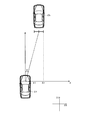
- FIG. 2 is a diagram for explaining position information of the target Ob detected by the controller.
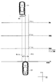
- FIG. 3 is a diagram for explaining the PCS executed by the driving support ECU.
- FIG. 4 is a diagram for explaining detection of the width of an object.
- FIG. 5 is a diagram for explaining the deviation amount DV.
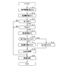
- FIG. 6 is a flowchart for explaining a lateral width correction process performed by the driving support ECU.
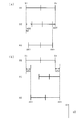
- FIG. 7 is a diagram for explaining the direction of deviation between the left and right end positions
- FIG. 8 is a view for explaining correction of the object width WO according to the second embodiment.
- FIG. 1 shows a pre-crash safety system (hereinafter referred to as PCSS: Pre-crash safety system) 100 to which an object detection device and an object detection method are applied.
- the PCSS 100 is an example of a vehicle system mounted on a vehicle, for example, detects an object positioned in front of the vehicle, and when there is a possibility of collision between the detected object and the vehicle, an operation of avoiding a collision of the own vehicle with the object Or, a collision mitigation operation is performed.
- a vehicle on which the PCSS 100 is mounted is referred to as a host vehicle CS
- an object to be detected is referred to as a target Ob.
- the PCSS 100 includes various sensors, a driving support ECU 20, a brake device 40, an alarm device 50, and a seat belt device 60.
- the driving assistance ECU 20 functions as an object detection device.
- the various sensors are connected to the driving support ECU 20 and output the detection result for the target Ob to the driving support ECU 20.
- the various sensors include a camera sensor 31 and a radar sensor 37.
- the camera sensor 31 is configured using, for example, a CCD camera, a CMOS image sensor, a near infrared camera, or the like.
- the camera sensor 31 is disposed on the front side of the host vehicle CS and recognizes the target Ob positioned in front of the host vehicle CS.
- the camera sensor 31 communicates between the imaging unit 32 that images the front of the vehicle, a controller 33 that performs known image processing on the captured image acquired by the imaging unit 32, and the controller 33 and the driving support ECU 20.
- ECUI / F36 which enables.
- the imaging unit 32 functions as an imaging unit.
- the imaging unit 32 includes a lens unit that functions as an optical system, and an imaging device that converts light collected through the lens unit into an electrical signal.
- an imaging device that converts light collected through the lens unit into an electrical signal.
- a known image sensor such as a CCD or a CMOS can be used.
- the electrical signal converted by the image sensor is stored in the controller 33 as a captured image through the ECU I / F 36.
- the controller 33 is configured by a known computer including a CPU, a ROM, a RAM, and the like. Further, the controller 33 functionally includes an object recognition unit 34 that recognizes the target Ob included in the captured image, and a position information calculation unit 35 that calculates position information of the recognized object.
- the object recognition unit 34 recognizes the target Ob using dictionary information for the captured image.
- the position information calculation unit 35 calculates the relative position of the recognized target Ob with respect to the host vehicle CS.
- the object recognition unit 34 acquires image data from the imaging unit 32, and based on the image data and dictionary information for object identification prepared in advance, the object Ob in front of the host vehicle Ob. Determine the type.
- the dictionary information for object identification is prepared individually according to the type of object such as an automobile, a two-wheeled vehicle, and a pedestrian, and is stored in advance in a memory.
- As the automobile dictionary information at least dictionary information of a front pattern and a rear pattern is preferably prepared. Two-wheeled vehicles should be distinguished from bicycles and motorcycles.
- the object recognition unit 34 compares the image data with the dictionary information and performs pattern matching to determine the type of the target Ob.
- the dictionary information may include fixed object dictionary information such as guardrails, utility poles, road signs, and the like in addition to the dictionary information of the moving object.
- the position information calculation unit 35 acquires position information indicating the left and right relative positions of the target Ob in the lateral direction D ⁇ b> 2 with respect to the imaging direction of the camera sensor 31.
- This position information includes a lateral position X (Xl, Xr) indicating the left and right end positions in the lateral direction D2 of the target Ob, and an azimuth angle ⁇ indicating the orientation from the host vehicle CS to the target Ob.
- the position information calculation unit 35 calculates the azimuth angle ⁇ using the lateral position X and the position of the host vehicle CS.
- the radar sensor 37 detects an object in front of the own vehicle using a directional electromagnetic wave such as a millimeter wave or a laser.
- the radar sensor 37 is attached so that its optical axis faces the front of the vehicle at the front of the host vehicle.
- the radar sensor 37 scans a region extending in a predetermined range toward the front of the vehicle with a transmission wave every predetermined time, and receives a reflected wave reflected on the surface of the front object, thereby detecting the distance from the front object and the front object.
- the relative speed and the like are acquired as object information.
- the acquired object information is input to the driving support ECU 20.
- the brake device 40 includes a brake mechanism that changes the braking force of the host vehicle CS and a brake ECU that controls the operation of the brake mechanism.
- the brake ECU is communicably connected to the driving support ECU 20, and controls the brake mechanism under the control of the driving support ECU 20.
- the brake mechanism includes, for example, a master cylinder, a wheel cylinder that applies braking force to the wheels, and an ABS actuator that adjusts the distribution of pressure (hydraulic pressure) from the master cylinder to the wheel cylinder.
- the ABS actuator is connected to the brake ECU, and adjusts the hydraulic pressure from the master cylinder to the wheel cylinder by the control from the brake ECU, thereby adjusting the operation amount for the wheel.
- the alarm device 50 warns the driver that the target Ob is present ahead of the host vehicle under the control of the driving support ECU 20.
- the alarm device 50 includes, for example, a speaker provided in the passenger compartment and a display unit that displays an image.
- the seat belt device 60 is a pretensioner that retracts a seat belt provided in each seat of the own vehicle.
- the seat belt device 60 performs a preliminary operation for retracting the seat belt when the possibility of the host vehicle CS colliding with the target Ob increases. If the collision cannot be avoided, the seat belt is retracted to remove the slack, thereby fixing the passenger such as the driver to the seat and protecting the passenger.
- the driving support ECU 20 is configured as a known microcomputer including a CPU, a ROM, and a RAM, and controls the host vehicle CS with reference to a calculation program and control data in the ROM. Further, the driving support ECU 20 detects the target Ob based on the captured image of the camera sensor 31, and performs PCS with at least one of the devices 40, 50, 60 as a control target based on the detection result.
- the driving assistance ECU 20 functions as a lateral width acquisition unit 21, a history calculation unit 22, a determination unit 23, a correction unit 24, and a collision determination unit 25 by executing a program stored in the ROM.
- the collision determination unit 25 determines the possibility of collision between the host vehicle CS and the target Ob. In this embodiment, the collision determination unit 25 determines the possibility of collision using the lateral position of the target Ob relative to the host vehicle CS.
- FIG. 3 shows the execution timing of each operation of the PCS, where the vertical axis is TTC and the horizontal axis is the horizontal position when the host vehicle CS is used as a reference. The closer the value of the vertical axis is to the host vehicle CS, the smaller the TTC, and the shorter the time until the target Ob collides with the host vehicle CS.
- the collision determination unit 25 uses the overlap ratio (lap ratio RR) between the object width WO indicating the size of the target Ob in the horizontal direction and the collision determination area CDA virtually set in front of the host vehicle.
- the possibility of collision of the mark Ob is determined.
- the collision determination area CDA is a virtual area having a predetermined width Wcda in the lateral direction of the vehicle and extending in the imaging axis direction (imaging direction) D1.
- the wrap rate RR is the amount of the object width WO that overlaps the width Wcda of the collision determination area CDA, and is calculated using the following equation (1).
- Lap rate RR WO / Wcda (1) Note that the inclination with respect to the imaging axis direction D1 of the collision determination area CDA is set based on the movement locus of the target Ob.
- the collision determination unit 25 calculates a margin time (TTC) indicating a time until the target Ob collides with the host vehicle CS. And the collision determination part 25 implements each operation
- TTC3 the strong deceleration which decelerates the own vehicle CS with the amount of deceleration stronger than TTC2 is implemented.
- the calculated wrap rate RR is reduced, and the collision avoidance control is appropriate even in a situation where there is a high possibility of actual collision with the target Ob. May not be implemented.
- the camera sensor 31 calculates the lateral position X based on the captured image and the dictionary information, and calculates the object width WO based on the lateral position X, the shape or pattern of the outer surface of the target Ob, It is conceivable that the object width WO is erroneously calculated too small depending on the mounted object or the like.
- the rear portion of the vehicle is provided with different uneven shapes and lamp devices for each vehicle type, and this object is used when calculating the object width WO. It may occur that the width WO is recognized narrower than the actual width.
- the actual object width WO is from the end point a1 to the end point a2 at the rear of the vehicle.
- a tail lamp or the like is provided at the rear part of the front vehicle, and it is conceivable that dictionary information is assigned to the shape or pattern of the tail lamp or the like.
- the horizontal width W1 between the change points b1 and b2, the horizontal width W2 between the change point b1 and the end point a2, and the like are calculated as the object width WO calculated from the image, so that the object width WO is recognized too small. Is done. Although illustration explanation is omitted, it is considered that the object width WO is recognized as being too small even for an object other than the vehicle.
- the driving support ECU 20 performs correction for extending the lateral position X.
- each function of the driving assistance ECU 20 for correcting the object width WO will be described.
- the horizontal width acquisition unit 21 acquires the object width WO.
- the horizontal width acquisition unit 21 acquires the horizontal position X and the azimuth angle ⁇ based on the position information output from the camera sensor 31, and indicates the size of the target Ob in the horizontal direction D2 using the acquired horizontal position X.
- the object width WO is calculated.
- the history calculation unit 22 records the lateral position X acquired by the horizontal width acquisition unit 21 as an acquisition history.
- the acquisition history records the horizontal position X for each type of target Ob when the horizontal position X is acquired at a predetermined cycle.
- the azimuth angle ⁇ is also recorded in the acquisition history.
- the determination unit 23 determines whether or not the object width WO acquired by the horizontal width acquisition unit 21 is small based on the comparison with the acquisition history.
- the latest lateral position X recorded in the acquisition history is referred to as the current lateral position XC
- the object width WO calculated by the lateral width acquisition unit 21 based on the latest lateral position XC is referred to as the current object width WC.
- the determination unit 23 calculates the estimated lateral width WE indicating the size of the target Ob in the lateral direction D2 based on the acquisition history, and compares the current object width WC with the estimated lateral width WE, It is determined whether or not the object width WC is small. Specifically, the determination unit 23 uses the largest object width WO calculated from the lateral position X recorded in the acquisition history as the estimated lateral width WE.
- the correction unit 24 determines the current deviation width DV based on the smaller deviation amount DV among the deviation amounts DV of the lateral position X of the target Ob.
- the lateral position XC is corrected.
- the object width WO is corrected to extend in the horizontal direction D2.
- the deviation DV is a value indicating the amount of change in the horizontal direction D2 between the right end point Xr and the left end point Xl of the current horizontal position XC.
- the correction unit 24 uses a difference from the current lateral position XC based on the estimated lateral width WE (maximum value of the object width WO) recorded in the acquisition history.
- the deviation amount DV is calculated.
- DVr
- DVl
- DVr and DVl indicate the left and right shift amounts of the lateral position X, respectively.
- Xr and Xl are the current lateral position XC.
- Xmr and Xml are lateral positions X in the maximum object width WO recorded in the acquisition history.
- the deviation amount DV is a value including zero. For example, when either the right end point Xr or the left end point Xl of the current horizontal position XC has not changed in the horizontal direction D2, the deviation amount DV is zero.
- each object width (t) shown in FIG. 5 corresponds to the object width WO calculated by the lateral width acquisition unit 21 at times t1 to t5, and the object width at the past time t as it goes from t5 to t1.
- WO is shown.
- the object width WO (t5) at time t5 is the current object width WC.
- the object width WO (t1) at the time t1 is the object width WO at which the object width WO is the maximum, the estimated width WE is obtained.
- the object width WO (t1) is used as a reference, in the current object width WC, the deviation amount DVl of the left end point Xl is larger than the deviation amount DVr of the right end point Xr.
- the correction unit 24 corrects the current lateral position XC by using the smaller deviation amount DV as the correction value ADV.
- the deviation amount DVr at the right end point Xr is smaller than the deviation amount DVl at the left end point Xl, the deviation amount DVr at the right end point Xr becomes the correction value ADV.
- the correction unit 24 corrects the current lateral position XC with the correction value ADV.
- the lateral position XC thus corrected is used by the collision determination unit 25 to determine the possibility of collision between the host vehicle CS and the target Ob as described above.
- This process is a process repeatedly performed by the driving support ECU 20 at a predetermined cycle.
- step S11 the current object width WC is calculated.
- the latest lateral position X recorded in the history information is acquired as the current lateral position XC, and the current object width WC is calculated based on the lateral position XC.
- Step S11 functions as a width acquisition step.
- step S12 the estimated lateral width WE is calculated using the acquisition history.
- a lateral position X that is the same type as the current object width WC calculated in step S11 and has the maximum object width WO is acquired from the acquisition history. Then, the estimated lateral width WE is calculated using the acquired lateral position X.
- step S13 it is determined whether or not the current object width WC is equal to or less than the estimated lateral width WE. For example, the current object width WC acquired in step S11 is compared with the estimated lateral width WE calculated in step S12. Step S13 functions as a determination step.
- step S13 If it is determined that the current object width WC is large (step S13: NO), the process proceeds to step S20. In this case, it is considered that the current lateral position XC is appropriate, and the current lateral position XC is updated as the lateral position X of the target Ob in step S20.
- step S14 it is determined whether or not the current lateral position XC is shifted in the lateral direction D2 with respect to the estimated lateral position XE. judge. If the current lateral position XC and the estimated lateral position XE are the same right end point Xr and left end point Xl, it can be considered that the object width WO has been properly acquired.
- step S14 when the current lateral position XC is not shifted in the lateral direction D2 with respect to the estimated lateral position XE (step S14: NO), the process proceeds to step S20, and the current lateral position XC is moved to the side of the target Ob. Update as position X.
- step S15 a correction value ADV corresponding to the smaller shift amount DV of the current horizontal position XC is calculated.
- the deviation amount DV is calculated for each of the right end point Xr and the left end point Xl using the above equation (2). Then, a smaller deviation amount DV is determined in comparison with the calculated deviation amount DV, and a correction value ADV corresponding to the deviation amount DV is calculated.
- the correction value ADV is the same value as the smaller deviation amount DV.
- step S16 it is determined whether or not the right end point Xr and the left end point Xl of the current lateral position XC are shifted in the same direction.
- the direction of deviation between the right end point Xr and the left end point Xl is determined according to the comparison between the right end point Xr and the left end point Xl between the estimated lateral position XE and the current lateral position XC.
- FIG. 7A shows a case where the direction of deviation of the object width WC is different. If the current object width WC is equal to or smaller than the estimated lateral width WE and the target Ob has not moved in the lateral direction D2, the current lateral position X is located inside the estimated lateral position XE.
- FIG. 7B shows a case where the direction of deviation between the right end point Xr and the left end point Xl is the same direction.
- the current object width WC is less than or equal to the estimated lateral width WE and the relative position of the host vehicle CS and the target Ob in the lateral direction D2 is changing
- the current lateral position XC is the estimated lateral position.
- both the right end point Xr and the left end point Xl are shifted in the relative movement direction of the host vehicle CS and the target Ob. For example, when the target Ob moves in the horizontal direction D2 or when the host vehicle CS moves in the horizontal direction D2, the direction of deviation between the right end point Xr and the left end point Xl is the same direction.
- step S17 using the correction value ADV calculated in step S15, the right end point Xr and the left end of the current lateral position XC.
- the point Xl is corrected so as to be shifted inward toward the azimuth angle ⁇ .
- the deviation amount DVr of the right end point Xr is smaller than the deviation amount DVl of the left end point Xl, and the right end point Xr is located inside the right end point Xr of the estimated lateral position XE.
- the right end point AXr and the left end point AX1 after correction are moved by moving the right end point Xr and the left end point Xl of the estimated lateral position XE to the center side by the correction value ADV calculated according to the deviation amount DV1 of the right end point Xr. And calculate.
- step S18 the right end point Xr of the current horizontal position XC is calculated using the correction value ADV calculated in step S15.
- the left end point Xl is corrected so as to be shifted in the moving direction of the target Ob.
- the right end point Xr of the current lateral position XC is located outside the right end point Xr of the estimated lateral position XE, thereby causing movement in the lateral direction D2.
- the corrected right end point AXr and left end point AXl are calculated by shifting the right end point Xr and the left end point Xl of the estimated lateral position XE to the right by the correction value ADV.
- Steps S17 and S18 function as a correction process.
- step S19 the azimuth angle ⁇ output from the camera sensor 31 is recalculated using the corrected right end point AXr and left end point AXl calculated in step S17 or step S18.
- the azimuth angle ⁇ is calculated using the corrected right end point AXr, left end point AX1, and the current position of the host vehicle CS.
- step S20 the lateral position X of the target Ob is updated.
- the corrected right end point AXr, left end point AXl, and azimuth angle ⁇ calculated in step S19 are updated as the corrected right end point Xr, left end point Xl, and azimuth angle ⁇ of the object width WO.
- the driving support ECU 20 is the smaller one of the left and right deviation amounts DV of the target Ob. Based on the deviation amount DV, the right end point Xr and the left end point Xl of the current lateral position XC are corrected. As a result, the right end point Xr and the left end point Xl are corrected by the same deviation amount DV with respect to the object width WO, and the right and left positions of the object width WO are prevented from greatly deviating in comparison with the true value.
- the object width can be acquired.
- the driving support ECU 20 uses the maximum value as the estimated horizontal width WE. With the above configuration, it is possible to prevent the object width WO from being excessively extended.
- the driving support ECU 20 sets the position where the previous object width WO is shifted in the horizontal direction D2 by the amount based on the smaller shift amount DV as the corrected horizontal position AX.
- the position shifted by the same shift amount DV from the lateral position X of the previous object width WO is set as the corrected lateral position X, so that the center of the object width WO is greatly shifted in comparison with the true value. Can be prevented.
- the driving support ECU 20 corrects the lateral position X of the object width WO in the same direction in which the deviation occurs based on the smaller deviation amount DV when the object width WO of the target Ob is shifted in the same direction on the left and right.
- the relative position in the horizontal direction D2 between the target Ob and the host vehicle CS changes, the horizontal position X of the target Ob changes in the same direction. Therefore, in such a case, the lateral position X is corrected in the same direction on the left and right based on the smaller deviation amount DV.
- the object width WO can be appropriately acquired even when the relative position in the lateral direction D2 between the target Ob and the host vehicle CS changes.
- the driving support ECU 20 replaces the maximum value of the object width WO recorded in the acquisition history with the estimated lateral position XE, and uses the previous object width WO recorded in the acquisition history as the estimated lateral width. Used as position XE.
- FIG. 8 shows a change in the object width WO from time t11 to t13 when the target Ob moves in the right direction (indicated by an arrow in the figure) in the horizontal direction D2.
- the object width WO (t13) at time t13 is the current object width WO
- the object width WO (t12) at time t12 is the previous object width WO.
- the driving support ECU 20 acquires the current object width WC (WO (t13)) based on the lateral position X at time t13 in step S11 of FIG.
- the estimated lateral width WE object width WO (t12) is acquired based on the estimated lateral position XE at time t12.
- step S15 the driving support ECU 20 calculates a correction value ADV corresponding to the smaller deviation amount DV between the estimated lateral width WE calculated according to the previous lateral position XO and the current lateral position XC.
- step S17 or step S18 the current lateral position XC is corrected in accordance with the calculated correction value ADV.
- the corrected object width WO (t13) is such that the object width WO extends in the lateral direction by changing the left end point Xl to the left.
- the amount of deviation of the object width WO includes those caused by erroneous acquisition of the object width WO and those caused by lateral movement of the object. Therefore, the driving assistance ECU 20 performs correction using the previous value of the object width WO. Due to the above configuration, even when the target Ob is moving in the horizontal direction, the difference between the previous value and the current value reduces the amount of deviation caused by the horizontal movement of the target Ob, so that the width of the target Ob is appropriate. Can be obtained.
- the driving support ECU 20 may calculate the lateral position X and azimuth angle ⁇ of the target Ob.
- the camera sensor 31 includes an imaging unit 32 and an ECU I / F 36 illustrated in FIG. 1, and the driving support ECU 20 functionally includes an object recognition unit 34 and a position information calculation unit 35.
- the driving assistance ECU 20 calculates the lateral position X and the azimuth angle ⁇ of the target Ob.
- the camera sensor 31 and the driving support ECU 20 may be configured as an integrated device.
- the camera sensor 31 includes functions of a lateral width acquisition unit 21, a history calculation unit 22, a determination unit 23, a correction unit 24, and a collision determination unit 25.
- the driving support device 10 may be configured to recognize the target Ob based on the detection result of the target Ob by the camera sensor 31 and the detection result of the target Ob by the radar sensor 37.
- the lateral position X at which the object width WO recorded in the acquisition history is maximum may be updated as the lateral position X of the target Ob. .
- the deviation amount DV may be calculated by comparing the current lateral position XC with an average value of a plurality of past lateral positions X recorded in the acquisition history. For example, the driving assistance ECU 20 calculates an average value of each of the right end point Xr and the left end point Xl of a plurality of past lateral positions X. Then, the deviation amount DV is calculated by comparing the right end point Xr and the left end point Xl of the current lateral position XC with the calculated average values of the right end point Xr and the left end point Xl.
- the collision determination unit 25 is the center point in the horizontal direction D2 obtained from the left and right end positions Xr and Xl. May be used to determine the possibility of collision between the host vehicle CS and the target Ob.
- the driving assistance ECU 20 calculates the position in the lateral direction D2 where the target Ob and the host vehicle CS may collide based on the movement locus of the position of the center point. Then, the possibility of collision is determined according to the calculated position in the lateral direction D2.
Landscapes
- Engineering & Computer Science (AREA)
- Physics & Mathematics (AREA)
- Radar, Positioning & Navigation (AREA)
- Remote Sensing (AREA)
- General Physics & Mathematics (AREA)
- Computer Networks & Wireless Communication (AREA)
- Electromagnetism (AREA)
- Transportation (AREA)
- Mechanical Engineering (AREA)
- Automation & Control Theory (AREA)
- Computer Vision & Pattern Recognition (AREA)
- Theoretical Computer Science (AREA)
- Geometry (AREA)
- Combustion & Propulsion (AREA)
- Chemical & Material Sciences (AREA)
- Human Computer Interaction (AREA)
- Traffic Control Systems (AREA)
- Control Of Driving Devices And Active Controlling Of Vehicle (AREA)
- Image Processing (AREA)
- Image Analysis (AREA)
Abstract
運転支援ECU20は、画像から前記撮像手段32の撮像方向に対する横方向での物体の大きさを横幅として取得する横幅取得部21と、今回の横幅を、前回以前の横幅と比較し、今回の横幅が前回以前の横幅よりも小さいか否かを判定する判定部23と、今回の横幅が前回以前の横幅よりも小さい場合に、物体の左右の両端位置のずれ量のうち小さい方のずれ量に基づいて、前記横幅の左右の両端位置を補正する補正部24と、を備える。
Description
本出願は、2016年4月1日に出願された日本出願番号2016-074643号に基づくもので、ここにその記載内容を援用する。
本開示は、撮像手段により撮像された画像に基づいて物体を検知する物体検知装置、及び物体検知方法に関する。
例えば特許文献1には、車両にレーダセンサを備え、このレーダセンサによる物体の反射点から物体の横方向での大きさである横幅を取得する装置が開示されている。特許文献1に記載された装置では、物体がレーダセンサの探索範囲の端に位置する場合や、物体の手前に他の物体が存在する場合に、この横幅の真値を検出できていないと判定する。そして、物体を検出できていないと判定した場合、履歴に記録された過去の横幅で今回の横幅を補正する。
特許文献1では、物体の横幅が正しく検出されていない場合でも、この横幅を過去の履歴情報に基づいて補正することで、横幅が適正に取得されていないことに起因した警報等が実施されるといった不都合が抑制される。
ところで、カメラ装置等の撮像手段により撮像された画像に基づいて物体の横幅を取得する場合、物体の横幅が誤って過小に取得される場合がある。物体の横幅の誤取得は、撮像手段との間の相対的な位置や、物体の手前に他の物体が存在するか否かにかかわらず生じ得る。そのため、特許文献1に記載された開示では、物体の横幅が過小に取得されている場合でも、物体の横幅を適正に検出できていると判定する場合がある。
本開示は上記課題に鑑みてなされたものであり、自車周辺に位置する物体の横幅を適正に取得することができる物体検知装置、物体検知方法を提供することを目的とする。
本開示では、撮像手段により撮像された画像に基づいて、車両周囲に存在する物体を検知する物体検知装置であって、前記画像から前記撮像手段の撮像方向に対する横方向での前記物体の大きさを横幅として取得する横幅取得部と、前記横幅取得部により取得された今回の横幅を、前回以前の横幅と比較し、前記今回の横幅が前回以前の横幅よりも小さいか否かを判定する判定部と、前記今回の横幅が前回以前の横幅よりも小さい場合に、物体の左右の両端位置のずれ量のうち小さい方のずれ量に基づいて、前記今回の横幅の左右の両端位置を補正する補正部と、を備える。
物体の外面の形状や模様、装着物等によって、横幅が誤って過小に取得されることが考えられる。この場合、物体の左右の両端位置ではそれぞれ位置ずれが生じるが、そのうち、ずれ量が小さい方は、大きい方よりもその位置が適正に取得されているとの考えに基づき、横幅の左右の両端位置のずれ量の大小関係を比較する。そして、今回の横幅が前回以前の横幅よりも小さい場合に、物体の左右の両端位置のずれ量のうち小さい方のずれ量に基づいて、横幅の左右の両端位置を補正する。これにより、横幅に対して左右の両端位置が同じずれ量により補正され、横幅の左右の両端位置が大きくずれるのを抑制し、適正な物体幅を取得することができる。
本開示についての上記目的およびその他の目的、特徴や利点は、添付の図面を参照しながら下記の詳細な記述により、より明確になる。その図面は、
図1は、PCSSを示す構成図であり、
図2は、コントローラにより検出される物標Obの位置情報を説明する図であり、
図3は、運転支援ECUにより実施されるPCSについて説明する図であり、
図4は、物体の幅の検出を説明する図であり、
図5は、ずれ量DVを説明する図であり、
図6は、運転支援ECUが実施する横幅の補正処理について説明するフローチャートであり、
図7は、左右の両端位置のずれの方向を説明する図であり、
図8は、第2実施形態に係る、物体幅WOの補正を説明する図である。
以下に本開示にかかる物体検知装置、及び物体検知方法の実施形態を図面と共に説明する。なお、以下の実施形態相互において、互いに同一もしくは均等である部分には、図中、同一符号を付しており、同一符号の部分についてはその説明を援用する。
(第1実施形態)
図1は、物体検知装置、及び物体検知方法を適用したプリクラッシュセーフティシステム(以下、PCSS:Pre-crash safety systemと記載する。)100を示している。PCSS100は、例えば、車両に搭載される車両システムの一例であり、車両前方に位置する物体を検出し、検出した物体と車両とが衝突するおそれがある場合、物体に対する自車両の衝突の回避動作、又は衝突の緩和動作を実施する。以下では、このPCSS100が搭載された車両を自車両CSと記載し、検出対象となる物体を物標Obと記載する。
図1は、物体検知装置、及び物体検知方法を適用したプリクラッシュセーフティシステム(以下、PCSS:Pre-crash safety systemと記載する。)100を示している。PCSS100は、例えば、車両に搭載される車両システムの一例であり、車両前方に位置する物体を検出し、検出した物体と車両とが衝突するおそれがある場合、物体に対する自車両の衝突の回避動作、又は衝突の緩和動作を実施する。以下では、このPCSS100が搭載された車両を自車両CSと記載し、検出対象となる物体を物標Obと記載する。
図1に示すように、PCSS100は、各種センサと、運転支援ECU20と、ブレーキ装置40と、警報装置50と、シートベルト装置60と、を備えている。図1に示す実施形態において、運転支援ECU20が物体検知装置として機能する。
各種センサは、運転支援ECU20に接続されており、物標Obに対する検出結果をこの運転支援ECU20に出力する。図1では、各種センサは、カメラセンサ31、レーダセンサ37を備えている。
カメラセンサ31は、例えばCCDカメラ、CMOSイメージセンサ、近赤外線カメラ等を用いて構成されている。カメラセンサ31は、自車両CSの前側に配置されており、自車前方に位置する物標Obを認識する。カメラセンサ31は、自車前方を撮像する撮像ユニット32と、この撮像ユニット32により取得された撮像画像に対して周知の画像処理を実施するコントローラ33と、コントローラ33と運転支援ECU20との通信を可能にするECUI/F36と、を備えている。撮像ユニット32は撮像手段として機能する。
撮像ユニット32は、光学系として機能するレンズ部や、このレンズ部を通じて集められた光を電気信号に変換する撮像素子を備えている。撮像素子は、CCDや、CMOS等周知の撮像素子を用いることができる。撮像素子により変換された電気信号は、ECUI/F36を通じて、撮像画像としてコントローラ33に記憶される。
コントローラ33は、CPU、ROM、RAM等を備える周知のコンピュータにより構成されている。また、コントローラ33は、撮像画像に含まれる物標Obを認識する物体認識部34と、認識された物体の位置情報を算出する位置情報算出部35と、を機能的に備えている。物体認識部34は、撮像画像に対して辞書情報を用いて物標Obを認識する。位置情報算出部35は、認識された物標Obの自車両CSに対する相対位置を算出する。
具体的には、物体認識部34は、撮像ユニット32からの画像データを取得し、その画像データと予め用意された物体識別用の辞書情報とに基づいて、自車前方にある物標Obの種類を判定する。物体識別用の辞書情報は、例えば自動車、二輪車、歩行者といった物体の種類に応じて個別に用意され、メモリに予め記憶されている。自動車の辞書情報としては、少なくとも前部パターンと後部パターンとの辞書情報が用意されているとよい。二輪車は、自転車とオートバイとの区別がなされているとよい。物体認識部34は、画像データと辞書情報とを照合し、パターンマッチングを行うことで、物標Obの種類を判定する。なお、辞書情報には、移動体の辞書情報以外に、ガードレールや電柱、道路標識等の固定物の辞書情報が含まれていてもよい。
図2に示す様に、位置情報算出部35は、カメラセンサ31の撮像方向に対する横方向D2での物標Obの左右の相対位置を示す位置情報を取得する。この位置情報は、物標Obの横方向D2での左右の両端位置を示す横位置X(Xl,Xr)と、自車両CSから物標Obまでの方位を示す方位角θと、を含んでいる。例えば、位置情報算出部35は、横位置Xと、自車両CSの位置と、を用いて方位角θを算出する。
レーダセンサ37は、ミリ波やレーザ等の指向性のある電磁波を利用して自車前方の物体を検出する。レーダセンサ37は、自車の前部においてその光軸が車両前方を向くように取り付けられている。レーダセンサ37は、所定時間ごとに車両前方に向かって所定範囲で広がる領域を送信波で走査するとともに、前方物体の表面で反射された反射波を受信することで前方物体との距離、前方物体との相対速度等を物体情報として取得する。取得された物体情報は、運転支援ECU20に入力される。
ブレーキ装置40は、自車両CSの制動力を変化させるブレーキ機構と、このブレーキ機構の動作を制御するブレーキECUとを備えている。ブレーキECUは、運転支援ECU20と通信可能に接続されており、運転支援ECU20の制御により、ブレーキ機構を制御する。ブレーキ機構は、例えば、マスターシリンダと、車輪に制動力を与えるホイルシリンダと、マスターシリンダからホイルシリンダへの圧力(油圧)の分配を調整するABSアクチュエータとを備えている。ABSアクチュエータは、ブレーキECUに接続されており、このブレーキECUからの制御によりマスターシリンダからホイルシリンダへの油圧を調整することで、車輪に対する作動量を調整する。
警報装置50は、運転支援ECU20の制御により、ドライバに対して自車前方に物標Obが存在することを警報する。警報装置50は、例えば、車室内に設けられたスピーカや、画像を表示する表示部により構成されている。
シートベルト装置60は、自車の各座席に設けられたシートベルトを引き込むプリテンショナである。シートベルト装置60は、自車両CSが物標Obに衝突する可能性が高まった場合に、シートベルトの引き込みの予備動作を行う。また衝突を回避できない場合には、シートベルトを引き込んで弛みを除くことにより、運転者等の乗員を座席に固定し、乗員の保護を行う。
運転支援ECU20は、CPU、ROM、RAMを備える周知のマイクロコンピュータとして構成されており、ROM内の演算プログラムや制御データを参照して、自車両CSに対する制御を実施する。また、運転支援ECU20は、カメラセンサ31の撮像画像に基づいて物標Obを検知し、その検知結果に基づいて、各装置40,50,60の少なくともいずれかを制御対象としてPCSを実施する。
運転支援ECU20は、ROMに記憶されたプログラムを実施することで、横幅取得部21、履歴算出部22、判定部23、補正部24、衝突判定部25、として機能する。
まずは、運転支援ECU20により実施されるPCSについて図3を用いて説明する。衝突判定部25は、自車両CSと物標Obとの衝突可能性を判定する。この実施形態では、衝突判定部25は、物標Obの自車両CSに対する相対的な横位置を用いて、衝突可能性を判定する。図3では、自車両CSを基準とした場合に、縦軸をTTCとし、横軸を横位置とする、PCSの各動作の実施タイミングを示している。縦軸の値が、自車両CSに近いほどTTCが少なくなり、物標Obが自車両CSに衝突するまでの時間が短いことを示している。
衝突判定部25は、物標Obの横方向での大きさを示す物体幅WOと自車前方に仮想的に設定された衝突判定領域CDAとの重なり率(ラップ率RR)を用いて、物標Obの衝突可能性を判定する。衝突判定領域CDAは、車両横方向に所定の幅Wcdaを有し、撮像軸方向(撮像方向)D1に延びた仮想的な領域である。ラップ率RRは、衝突判定領域CDAの幅Wcdaに重なる物体幅WOの量であり、下記式(1)を用いて算出される。ラップ率RR=WO/Wcda … (1)
なお、衝突判定領域CDAの撮像軸方向D1を基準とする傾きは、物標Obの移動軌跡に基づいて設定される。
なお、衝突判定領域CDAの撮像軸方向D1を基準とする傾きは、物標Obの移動軌跡に基づいて設定される。
また、衝突判定部25は、ラップ率RRが所定値以上である場合、物標Obが自車両CSに衝突するまでの時間を示す余裕時間(TTC)を算出する。そして、衝突判定部25は、TTCに応じて、PCSの各動作を実施する。例えば、この実施形態では、衝突判定部25は、TTC1では、警報装置50を制御してドライバに対して物標Obが進行方向前方に存在することを警報する。また、TTC2では、ブレーキ装置40を制御して、自車両CSを所定量だけ弱減速させる自動ブレーキを実施する。そして、TTC3では、ブレーキ装置40の制御による減速と、シートベルト装置60のテンションを増加させる予備動作とを実施する。ここで、TTC3では、TTC2と比べて強い減速量で自車両CSを減速させる強減速を実施する。
ラップ率RRの判定において、物体幅WOが過小に認識されると、算出されるラップ率RRが少なくなり、物標Obに対する現実の衝突可能性が高い状況にあっても、衝突回避制御が適正に実施されないおそれがある。具体的には、カメラセンサ31が撮像画像と辞書情報とに基づいて横位置Xを算出し、この横位置Xに基づいて物体幅WOを算出する場合、物標Obの外面の形状や模様、装着物等によっては、物体幅WOが誤って過小に算出されることが考えられる。また、自車両CSの前方を走行する車両を物標Obとする場合、車両後部には、車種ごとに異なる凹凸形状やランプ装置が設けられており、物体幅WOを算出する際に、この物体幅WOを実横幅よりも狭く認識してしまうことが生じ得る。
図4(a)、(b)に示す車両において、実際の物体幅WOは車両後部の端点a1から端点a2までである。ただし、前方車の後部にはテールランプ等が設けられており、そのテールランプ等の形状や模様に対して辞書情報があてがわれることが考えられる。つまり、車両後部には、例えばテールランプにより、端点a1,a2以外に外観の変化点b1,b2が存在しており、その変化点b1,b2が車体後部の端部として認識されることがある。この場合、変化点b1,b2間の横幅W1や、変化点b1と端点a2との間の横幅W2等が画像から算出される物体幅WOとして算出されることで、物体幅WOが過小に認識される。なお、図示による説明は省略するが、車両以外の物体であっても、やはり同様に物体幅WOが過小に認識されることが生じると考えられる。
そのため、運転支援ECU20は、物体幅WOが過小に認識されるおそれがある場合、横位置Xを延長する補正を行うこととしている。次に、物体幅WOを補正するための運転支援ECU20の各機能を説明する。
図1に戻り、横幅取得部21は、物体幅WOを取得する。横幅取得部21は、カメラセンサ31から出力される位置情報により、横位置Xや方位角θを取得し、取得された横位置Xを用いて横方向D2での物標Obの大きさを示す物体幅WOを算出する。
履歴算出部22は、横幅取得部21が取得した横位置Xを取得履歴として記録する。なお、取得履歴は、所定周期で横位置Xが取得される場合において、物標Obの種別毎に、横位置Xを記録していく。また、取得履歴には、横位置Xに加えて、方位角θも記録される。
判定部23は、取得履歴との比較に基づいて、横幅取得部21が今回取得した物体幅WOが小さいか否かを判定する。以下では、取得履歴に記録された最新の横位置Xを今回の横位置XCと記載し、横幅取得部21が最新の横位置XCにより算出する物体幅WOを今回の物体幅WCと記載する。また、判定部23は、取得履歴に基づいて、物標Obの横方向D2での大きさを示す推定横幅WEを算出し、今回の物体幅WCを推定横幅WEと比較することで、今回の物体幅WCが小さいか否かを判定する。具体的には、判定部23は、取得履歴に記録された横位置Xにより算出される物体幅WOのうち最も大きくなるものを、推定横幅WEとして使用する。
補正部24は、今回の物体幅WCが推定横幅WEと比べて小さいと判定された場合、物標Obの横位置Xのずれ量DVのうち、小さい方のずれ量DVに基づいて、今回の横位置XCを補正する。補正部24による今回の横位置XCの補正により、物体幅WOが横方向D2に延長するよう補正される。
ずれ量DVは、今回の横位置XCの右端点Xrと左端点Xlとの横方向D2での変化量を示す値である。この実施形態では、補正部24は、下記式(2)に示すように、取得履歴に記録された推定横幅WE(物体幅WOの最大値)を基準として、今回の横位置XCとの差分によりずれ量DVを算出する。
DVr=|Xmr-Xr|
DVl=|Xml-Xl| … (2)
ここで、DVr,DVlは、それぞれ横位置Xの左右のずれ量を示している。また、この実施形態では、Xr,Xlは、今回の横位置XCである。Xmr,Xmlは、取得履歴に記録された最大の物体幅WOにおける横位置Xである。
DVr=|Xmr-Xr|
DVl=|Xml-Xl| … (2)
ここで、DVr,DVlは、それぞれ横位置Xの左右のずれ量を示している。また、この実施形態では、Xr,Xlは、今回の横位置XCである。Xmr,Xmlは、取得履歴に記録された最大の物体幅WOにおける横位置Xである。
ずれ量DVは、0を含む値である。例えば、今回の横位置XCの右端点Xr又は左端点Xlのいずれかが横方向D2に変化していない場合、ずれ量DVは0となる。
例えば、図5に示す各物体幅(t)は、時刻t1~t5において横幅取得部21が算出した物体幅WOに対応しており、t5からt1に向かうに従い、過去の時刻tでの物体幅WOを示している。このうち、時刻t5における物体幅WO(t5)が今回の物体幅WCである。また、時刻t1での物体幅WO(t1)が、物体幅WOが最大となる物体幅WOであるため、推定横幅WEとなる。この例では、物体幅WO(t1)を基準とした場合、今回の物体幅WCは、左端点Xlのずれ量DVlが右端点Xrのずれ量DVrよりも大きくなっている。
補正部24は、小さい方のずれ量DVを補正値ADVとして用いることで今回の横位置XCを補正する。図5の例では、右端点Xrでのずれ量DVrが左端点Xlでのずれ量DVlよりも小さくなっているため、右端点Xrでのずれ量DVrが補正値ADVとなる。そして、補正部24は、この補正値ADVにより今回の横位置XCを補正する。こうして補正された今回の横位置XCは、上述したように衝突判定部25により自車両CSと物標Obとの衝突可能性を判定するために用いられる。
次に、運転支援ECU20により実施される物体幅WOの補正処理について、図6のフローチャートを用いて説明する。本処理は、運転支援ECU20により所定周期で繰り返し実施される処理である。
ステップS11では、今回の物体幅WCを算出する。履歴情報に記録されている最新の横位置Xを今回の横位置XCとして取得し、この横位置XCに基づいて今回の物体幅WCを算出する。ステップS11が横幅取得工程として機能する。
ステップS12では、取得履歴を用いて推定横幅WEを算出する。この第1実施形態では、ステップS11で算出した今回の物体幅WCと同一種別であって、物体幅WOが最大となる横位置Xを取得履歴から取得する。そして、取得した横位置Xを用いて、推定横幅WEを算出する。
ステップS13では、今回の物体幅WCが、推定横幅WE以下であるか否かを判定する。例えば、ステップS11で取得した今回の物体幅WCと、ステップS12で算出した推定横幅WEとを比較する。ステップS13が判定工程として機能する。
今回の物体幅WCが大きいと判定した場合(ステップS13:NO)、ステップS20に進む。この場合、今回の横位置XCは適正であると考え、ステップS20で、今回の横位置XCを物標Obの横位置Xとして更新する。
一方、今回の物体幅WCが推定横幅WE未満である場合(ステップS13:YES)、ステップS14では、今回の横位置XCが、推定横位置XEを基準として横方向D2にずれているか否かを判定する。今回の横位置XCと推定横位置XEが同じ右端点Xr及び左端点Xlである場合、物体幅WOが適正に取得されていると見なすことができる。そのため、ステップS14において、今回の横位置XCが推定横位置XEに対して横方向D2にずれていない場合(ステップS14:NO)、ステップS20に進み、今回の横位置XCを物標Obの横位置Xとして更新する。
今回の横位置XCが横方向D2にずれている場合(ステップS14:YES)、ステップS15では、今回の横位置XCの小さい方のずれ量DVに応じた補正値ADVを算出する。上記式(2)を用いて右端点Xrと左端点Xlとについてそれぞれずれ量DVを算出する。そして、算出したずれ量DVの比較により小さい方のずれ量DVを判定し、このずれ量DVに応じた補正値ADVを算出する。なお、この実施形態では、補正値ADVは、小さい方のずれ量DVと同じ値としている。
ステップS16では、今回の横位置XCの右端点Xrと左端点Xlとが同じ方向にずれているか否かを判定する。右端点Xrと左端点Xlのずれの方向は、推定横位置XEと今回の横位置XCとの右端点Xr及び左端点Xlの比較に応じて判定される。
図7(a)では、物体幅WCのずれの方向が異なる場合を示している。今回の物体幅WCが推定横幅WE以下であり、かつ、物標Obが横方向D2に移動していなければ、今回の横位置Xは、推定横位置XEよりも内側に位置することとなる。
図7(b)では、右端点Xrと左端点Xlとのずれの方向が同じ方向である場合を示している。今回の物体幅WCが推定横幅WE以下であり、かつ、自車両CSと物標Obとの横方向D2での相対的な位置が変化している場合、今回の横位置XCは、推定横位置XEとの比較において、右端点Xr及び左端点Xlが共に自車両CSと物標Obとの相対的な移動方向にずれている。例えば、物標Obが横方向D2に移動する場合や、自車両CSが横方向D2に移動する場合、右端点Xrと左端点Xlとのずれの方向が同じ向きとなる。
右端点Xrと左端点Xlとが異なる方向にずれている場合(ステップS16:NO)、ステップS17では、ステップS15で算出した補正値ADVを用いて、今回の横位置XCの右端点Xrと左端点Xlとを方位角θに向けて内側にずらすよう補正する。図7(a)では、右端点Xrのずれ量DVrが左端点Xlのずれ量DVlよりも小さく、かつ、右端点Xrが推定横位置XEの右端点Xrよりも内側に位置している。そのため、推定横位置XEの右端点Xrと左端点Xlとを、右端点Xrのずれ量DVlに応じて算出する補正値ADVだけ中心側に移動させることで補正後の右端点AXrと左端点AXlとを算出する。
一方、右端点Xrと左端点Xlとが同じ方向にずれている場合(ステップS16:YES)、ステップS18では、ステップS15で算出した補正値ADVを用いて今回の横位置XCの右端点Xrと左端点Xlとを物標Obの移動方向にずらすよう補正する。図7(b)では、今回の横位置XCの右端点Xrが推定横位置XEの右端点Xrよりも外側に位置することで、横方向D2での移動が生じている。そのため、推定横位置XEの右端点Xrと左端点Xlとに対して、補正値ADVだけ右方向にずらすことで、補正後の右端点AXrと左端点AXlとを算出する。ステップS17及びステップS18が補正工程として機能する。
ステップS19では、ステップS17又はステップS18で算出した補正後の右端点AXrと左端点AXlとを用いてカメラセンサ31から出力された方位角θを再演算する。例えば、補正後の右端点AXrと左端点AXlと、現在の自車両CSの位置と、を用いて方位角θを算出する。
ステップS20では、物標Obの横位置Xを更新する。この場合、補正後の右端点AXr、左端点AXl及びステップS19で算出した方位角θを、補正後の物体幅WOの右端点Xr、左端点Xl及び方位角θとして更新する。
以上説明したように、この第1実施形態では、運転支援ECU20は、今回の物体幅WCが前回以前の物体幅WOよりも小さい場合に、物標Obの左右のずれ量DVのうち小さい方のずれ量DVに基づいて、今回の横位置XCの右端点Xrと左端点Xlとを補正する。これにより、物体幅WOに対して右端点Xrと左端点Xlとが同じずれ量DVにより補正され、真値との比較において、物体幅WOの左右の位置が大きくずれるのを抑制し、適正な物体幅を取得することができる。
物体幅の真値が前回以前の横幅の最大値を超える可能性は低いため、運転支援ECU20は、この最大値を推定横幅WEとして用いることとした。上記構成により、物体幅WOが過度に延長されてしまうのを防止することができる。
運転支援ECU20は、前回以前の物体幅WOを小さい方のずれ量DVに基づく量だけ横方向D2にずらした位置を、補正後の横位置AXとした。上記構成により、前回以前の物体幅WOの横位置Xから同じずれ量DV分だけずらした位置を補正後の横位置Xとすることで、物体幅WOの中心が真値との比較において大きくずれるのを防止することができる。
運転支援ECU20は、物標Obの物体幅WOが左右同じ方向にずれる場合、小さい方のずれ量DVに基づいて物体幅WOの横位置Xをずれが生じている同じ方向に補正する。物標Obと自車両CSとの横方向D2での相対位置が変化する場合、物標Obの横位置Xは同じ方向に変化する。そのため、このような場合は、小さい方のずれ量DVに基づいて横位置Xを左右同じ方向に補正することとした。上記構成により、物標Obと自車両CSとの横方向D2での相対位置が変化する場合でも、物体幅WOを適正に取得することができる。
(第2実施形態)
この第2実施形態では、運転支援ECU20は、取得履歴に記録された物体幅WOの最大値を推定横位置XEとして用いることに代えて、取得履歴に記録された前回の物体幅WOを推定横位置XEとして使用する。
この第2実施形態では、運転支援ECU20は、取得履歴に記録された物体幅WOの最大値を推定横位置XEとして用いることに代えて、取得履歴に記録された前回の物体幅WOを推定横位置XEとして使用する。
図8では、物標Obが横方向D2における右方向(図中矢印で示す)に移動する場合の、時刻t11~t13での物体幅WOの変化を示している。また、時刻t13での物体幅WO(t13)を今回の物体幅WOとし、時刻t12での物体幅WO(t12)を前回の物体幅WOとしている。
図8に示す例では、運転支援ECU20は、図6のステップS11において、時刻t13での横位置Xに基づいて、今回の物体幅WC(WO(t13))を取得する。次に、ステップS12において、時刻t12での推定横位置XEに基づいて、推定横幅WE(物体幅WO(t12))を取得する。
また、ステップS15では、運転支援ECU20は、前回の横位置XOに応じて算出された推定横幅WEと今回の横位置XCとの小さい方のずれ量DVに応じた補正値ADVを算出する。そして、ステップS17又はステップS18において、算出された補正値ADVに応じて、今回の横位置XCを補正する。図8では、補正後の物体幅WO(t13)は、左端点Xlが左方向に変更されることで、物体幅WOが横方向に延長している。
以上説明したように、物標Obが横移動する場合、物体幅WOのずれ量には、物体幅WOの誤取得に起因するものと、物体の横移動に起因するものとが含まれる。そこで、運転支援ECU20は、物体幅WOの前回値を用いて補正を行うこととした。上記構成により、物標Obが横方向に移動している場合でも、前回値と今回値との差により、物標Obの横移動に起因するずれ量が減殺され、物標Obの横幅を適正に取得することができる。
(その他の実施形態)
カメラセンサ31が物標Obの横位置Xや方位角θを算出する代わりに、運転支援ECU20が物標Obの横位置Xや方位角θを算出するものであってもよい。この場合、カメラセンサ31は、図1に示す、撮像ユニット32とECUI/F36とを備え、運転支援ECU20は、物体認識部34と位置情報算出部35とを機能的に備える。そして、カメラセンサ31から出力された撮像画像に基づいて、運転支援ECU20は、物標Obの横位置Xや方位角θを算出する。
カメラセンサ31が物標Obの横位置Xや方位角θを算出する代わりに、運転支援ECU20が物標Obの横位置Xや方位角θを算出するものであってもよい。この場合、カメラセンサ31は、図1に示す、撮像ユニット32とECUI/F36とを備え、運転支援ECU20は、物体認識部34と位置情報算出部35とを機能的に備える。そして、カメラセンサ31から出力された撮像画像に基づいて、運転支援ECU20は、物標Obの横位置Xや方位角θを算出する。
また、カメラセンサ31と、運転支援ECU20とが一体の装置として構成されるものであってもよい。この場合、カメラセンサ31は、横幅取得部21、履歴算出部22、判定部23、補正部24、衝突判定部25の各機能を備える。
また、運転支援装置10は、カメラセンサ31による物標Obの検出結果と、レーダセンサ37による物標Obの検出結果とに基づいて、物標Obを認識する構成としてもよい。
図6のステップS13において、今回の物体幅WCが大きいと判定された場合、取得履歴に記録された物体幅WOが最大となる横位置Xを物標Obの横位置Xとして更新してもよい。
ずれ量DVを算出するに際し、今回の横位置XCと、取得履歴に記録された複数の過去の横位置Xの平均値との比較によりずれ量DVを算出してもよい。例えば、運転支援ECU20は、複数の過去の横位置Xの右端点Xrと左端点Xlとのそれぞれの平均値を算出する。そして、今回の横位置XCの右端点Xrと左端点Xlとを、算出した右端点Xr及び左端点Xlのそれぞれの平均値と比較することで、ずれ量DVを算出する。
衝突判定部25は、物体幅WOを用いて自車両CSと物標Obとの衝突可能性を判定することに代えて、左右の両端位置Xr,Xlにより求められた横方向D2での中心点の位置を用いて、自車両CSと物標Obとの衝突可能性を判定するものであってもよい。この場合、運転支援ECU20は、中心点の位置の移動軌跡に基づいて、物標Obと自車両CSとが衝突するおそれがある横方向D2での位置を算出する。そして、算出された横方向D2での位置に応じて、衝突可能性を判定する。
本開示は、実施例に準拠して記述されたが、本開示は当該実施例や構造に限定されるものではないと理解される。本開示は、様々な変形例や均等範囲内の変形をも包含する。加えて、様々な組み合わせや形態、さらには、それらに一要素のみ、それ以上、あるいはそれ以下、を含む他の組み合わせや形態をも、本開示の範疇や思想範囲に入るものである。
Claims (6)
- 撮像手段(32)により撮像された画像に基づいて、車両周囲に存在する物体を検知する物体検知装置(20)であって、
前記画像から前記撮像手段の撮像方向に対する横方向での前記物体の大きさを横幅として取得する横幅取得部(21)と、
前記横幅取得部により取得された今回の横幅を、前回以前の横幅と比較し、前記今回の横幅が前回以前の横幅よりも小さいか否かを判定する判定部(23)と、
前記今回の横幅が前回以前の横幅よりも小さい場合に、物体の左右の両端位置のずれ量のうち小さい方のずれ量に基づいて、前記今回の横幅の左右の両端位置を補正する補正部(24)と、を備える物体検知装置。 - 前記判定部は、前記前回以前の横幅として、最大の横幅を用いて前記判定を行う、請求項1に記載の物体検知装置。
- 前記補正部は、前記前回以前の横幅の前記左右の両端位置を前記小さい方のずれ量に基づく量だけ前記横方向にずらした位置を、補正後の前記左右の両端位置とする、請求項1又は請求項2に記載の物体検知装置。
- 前記補正部は、前記前回以前の横幅として、前記横幅取得部により取得された前回の横幅を用いて前記補正を行う、請求項3に記載の物体検知装置。
- 前記補正部は、前記物体の左右の両端位置が左右同じ方向にずれる場合、前記小さい方のずれ量に基づいて前記左右の両端位置を前記ずれが生じている同じ方向に補正する、請求項1から請求項4のいずれか一項に記載の物体検知装置。
- 撮像手段により撮像された画像に基づいて、車両周囲に存在する物体を検知する物体検知方法であって、
前記画像から前記撮像手段の撮像方向に対する横方向での前記物体の大きさを横幅として取得する横幅取得工程と、
前記横幅取得工程で取得された今回の横幅を、前回以前の横幅と比較し、前記今回の横幅が前回以前の横幅よりも小さいか否かを判定する判定工程と、
前記今回の横幅が前回以前の横幅よりも小さい場合に、物体の左右の両端位置のずれ量のうち小さい方のずれ量に基づいて、前記今回の横幅の左右の両端位置を補正する補正工程と、を備える物体検知方法。
Priority Applications (1)
| Application Number | Priority Date | Filing Date | Title |
|---|---|---|---|
| US16/088,728 US10775497B2 (en) | 2016-04-01 | 2017-03-31 | Object detection device and object detection method |
Applications Claiming Priority (2)
| Application Number | Priority Date | Filing Date | Title |
|---|---|---|---|
| JP2016074643A JP6493280B2 (ja) | 2016-04-01 | 2016-04-01 | 物体検知装置、物体検知方法 |
| JP2016-074643 | 2016-04-01 |
Publications (1)
| Publication Number | Publication Date |
|---|---|
| WO2017171083A1 true WO2017171083A1 (ja) | 2017-10-05 |
Family
ID=59964858
Family Applications (1)
| Application Number | Title | Priority Date | Filing Date |
|---|---|---|---|
| PCT/JP2017/013835 Ceased WO2017171083A1 (ja) | 2016-04-01 | 2017-03-31 | 物体検知装置、物体検知方法 |
Country Status (3)
| Country | Link |
|---|---|
| US (1) | US10775497B2 (ja) |
| JP (1) | JP6493280B2 (ja) |
| WO (1) | WO2017171083A1 (ja) |
Families Citing this family (4)
| Publication number | Priority date | Publication date | Assignee | Title |
|---|---|---|---|---|
| JP6462630B2 (ja) * | 2016-05-24 | 2019-01-30 | 株式会社デンソー | 物標検出装置 |
| JP7216695B2 (ja) * | 2020-11-04 | 2023-02-01 | 本田技研工業株式会社 | 周囲車両監視装置及び周囲車両監視方法 |
| US12371184B2 (en) * | 2022-01-03 | 2025-07-29 | Honeywell International Inc. | Systems and methods for presenting a qualitative risk assessment for an aircraft to perform a flight procedure |
| JP7653463B2 (ja) * | 2023-03-24 | 2025-03-28 | 本田技研工業株式会社 | 制御装置 |
Citations (2)
| Publication number | Priority date | Publication date | Assignee | Title |
|---|---|---|---|---|
| JP2002296350A (ja) * | 2001-03-30 | 2002-10-09 | Nissan Motor Co Ltd | 物体検知装置 |
| JP2015210610A (ja) * | 2014-04-24 | 2015-11-24 | 本田技研工業株式会社 | 車両認識装置 |
Family Cites Families (10)
| Publication number | Priority date | Publication date | Assignee | Title |
|---|---|---|---|---|
| JP3997837B2 (ja) * | 2002-05-27 | 2007-10-24 | 株式会社デンソー | 車載レーダ装置、プログラム |
| JP2003346163A (ja) * | 2002-05-27 | 2003-12-05 | Nissan Motor Co Ltd | 車両用走行路認識装置 |
| JP3757936B2 (ja) * | 2002-11-29 | 2006-03-22 | 株式会社デンソー | 車両用障害物認識装置 |
| JP4534846B2 (ja) | 2005-04-13 | 2010-09-01 | トヨタ自動車株式会社 | 物体検出装置 |
| JP2009265925A (ja) * | 2008-04-24 | 2009-11-12 | Canon Inc | 画像処理装置及びその方法 |
| JP5929870B2 (ja) * | 2013-10-17 | 2016-06-08 | 株式会社デンソー | 物標検出装置 |
| JP2015132553A (ja) | 2014-01-14 | 2015-07-23 | トヨタ自動車株式会社 | 物体検出装置 |
| JP5969534B2 (ja) * | 2014-04-21 | 2016-08-17 | 株式会社デンソー | 走行支援装置 |
| JP6384446B2 (ja) * | 2015-10-14 | 2018-09-05 | 株式会社デンソー | 車両制御装置、車両制御方法 |
| JP6673178B2 (ja) * | 2016-12-14 | 2020-03-25 | 株式会社デンソー | 車両制御装置、車両制御方法 |
-
2016
- 2016-04-01 JP JP2016074643A patent/JP6493280B2/ja active Active
-
2017
- 2017-03-31 WO PCT/JP2017/013835 patent/WO2017171083A1/ja not_active Ceased
- 2017-03-31 US US16/088,728 patent/US10775497B2/en active Active
Patent Citations (2)
| Publication number | Priority date | Publication date | Assignee | Title |
|---|---|---|---|---|
| JP2002296350A (ja) * | 2001-03-30 | 2002-10-09 | Nissan Motor Co Ltd | 物体検知装置 |
| JP2015210610A (ja) * | 2014-04-24 | 2015-11-24 | 本田技研工業株式会社 | 車両認識装置 |
Also Published As
| Publication number | Publication date |
|---|---|
| US10775497B2 (en) | 2020-09-15 |
| US20190113615A1 (en) | 2019-04-18 |
| JP6493280B2 (ja) | 2019-04-03 |
| JP2017187865A (ja) | 2017-10-12 |
Similar Documents
| Publication | Publication Date | Title |
|---|---|---|
| US10854081B2 (en) | Driving assistance device and driving assistance method | |
| CN108156822B (zh) | 车辆控制装置,以及车辆控制方法 | |
| EP2803547B1 (en) | Collision mitigation apparatus | |
| EP3039450B1 (en) | In-vehicle control device | |
| US10793096B2 (en) | Vehicle control device with object detection | |
| US10535264B2 (en) | Object detection apparatus and object detection method | |
| US11288961B2 (en) | Vehicle control apparatus and vehicle control method | |
| CN108885833B (zh) | 车辆检知装置 | |
| US10578714B2 (en) | Vehicle control apparatus and vehicle control method | |
| WO2017179469A1 (ja) | 車両制御装置、及び車両制御方法 | |
| JP6493280B2 (ja) | 物体検知装置、物体検知方法 | |
| US11890939B2 (en) | Driver assistance system | |
| JP6613982B2 (ja) | 車両制御装置、車両制御方法 | |
| US10803327B2 (en) | Object detection apparatus | |
| US10814841B2 (en) | Driving support control apparatus and driving support control method of controlling vehicle braking | |
| US20190061751A1 (en) | Crossing determination apparatus | |
| US20220366702A1 (en) | Object detection device |
Legal Events
| Date | Code | Title | Description |
|---|---|---|---|
| NENP | Non-entry into the national phase |
Ref country code: DE |
|
| 121 | Ep: the epo has been informed by wipo that ep was designated in this application |
Ref document number: 17775614 Country of ref document: EP Kind code of ref document: A1 |
|
| 122 | Ep: pct application non-entry in european phase |
Ref document number: 17775614 Country of ref document: EP Kind code of ref document: A1 |