WO2017170752A1 - 回転コネクタ装置 - Google Patents
回転コネクタ装置 Download PDFInfo
- Publication number
- WO2017170752A1 WO2017170752A1 PCT/JP2017/013031 JP2017013031W WO2017170752A1 WO 2017170752 A1 WO2017170752 A1 WO 2017170752A1 JP 2017013031 W JP2017013031 W JP 2017013031W WO 2017170752 A1 WO2017170752 A1 WO 2017170752A1
- Authority
- WO
- WIPO (PCT)
- Prior art keywords
- ring plate
- outer peripheral
- stator
- fixed
- connector device
- Prior art date
- Legal status (The legal status is an assumption and is not a legal conclusion. Google has not performed a legal analysis and makes no representation as to the accuracy of the status listed.)
- Ceased
Links
Images




Classifications
-
- H—ELECTRICITY
- H01—ELECTRIC ELEMENTS
- H01R—ELECTRICALLY-CONDUCTIVE CONNECTIONS; STRUCTURAL ASSOCIATIONS OF A PLURALITY OF MUTUALLY-INSULATED ELECTRICAL CONNECTING ELEMENTS; COUPLING DEVICES; CURRENT COLLECTORS
- H01R35/00—Flexible or turnable line connectors, i.e. the rotation angle being limited
- H01R35/02—Flexible line connectors without frictional contact members
- H01R35/025—Flexible line connectors without frictional contact members having a flexible conductor wound around a rotation axis
-
- H—ELECTRICITY
- H01—ELECTRIC ELEMENTS
- H01R—ELECTRICALLY-CONDUCTIVE CONNECTIONS; STRUCTURAL ASSOCIATIONS OF A PLURALITY OF MUTUALLY-INSULATED ELECTRICAL CONNECTING ELEMENTS; COUPLING DEVICES; CURRENT COLLECTORS
- H01R35/00—Flexible or turnable line connectors, i.e. the rotation angle being limited
- H01R35/04—Turnable line connectors with limited rotation angle with frictional contact members
-
- B—PERFORMING OPERATIONS; TRANSPORTING
- B60—VEHICLES IN GENERAL
- B60R—VEHICLES, VEHICLE FITTINGS, OR VEHICLE PARTS, NOT OTHERWISE PROVIDED FOR
- B60R16/00—Electric or fluid circuits specially adapted for vehicles and not otherwise provided for; Arrangement of elements of electric or fluid circuits specially adapted for vehicles and not otherwise provided for
- B60R16/02—Electric or fluid circuits specially adapted for vehicles and not otherwise provided for; Arrangement of elements of electric or fluid circuits specially adapted for vehicles and not otherwise provided for electric constitutive elements
- B60R16/023—Electric or fluid circuits specially adapted for vehicles and not otherwise provided for; Arrangement of elements of electric or fluid circuits specially adapted for vehicles and not otherwise provided for electric constitutive elements for transmission of signals between vehicle parts or subsystems
- B60R16/027—Electric or fluid circuits specially adapted for vehicles and not otherwise provided for; Arrangement of elements of electric or fluid circuits specially adapted for vehicles and not otherwise provided for electric constitutive elements for transmission of signals between vehicle parts or subsystems between relatively movable parts of the vehicle, e.g. between steering wheel and column
-
- B—PERFORMING OPERATIONS; TRANSPORTING
- B62—LAND VEHICLES FOR TRAVELLING OTHERWISE THAN ON RAILS
- B62D—MOTOR VEHICLES; TRAILERS
- B62D1/00—Steering controls, i.e. means for initiating a change of direction of the vehicle
- B62D1/02—Steering controls, i.e. means for initiating a change of direction of the vehicle vehicle-mounted
- B62D1/04—Hand wheels
- B62D1/10—Hubs; Connecting hubs to steering columns, e.g. adjustable
-
- H—ELECTRICITY
- H01—ELECTRIC ELEMENTS
- H01R—ELECTRICALLY-CONDUCTIVE CONNECTIONS; STRUCTURAL ASSOCIATIONS OF A PLURALITY OF MUTUALLY-INSULATED ELECTRICAL CONNECTING ELEMENTS; COUPLING DEVICES; CURRENT COLLECTORS
- H01R13/00—Details of coupling devices of the kinds covered by groups H01R12/70 or H01R24/00 - H01R33/00
- H01R13/46—Bases; Cases
- H01R13/52—Dustproof, splashproof, drip-proof, waterproof, or flameproof cases
-
- H—ELECTRICITY
- H01—ELECTRIC ELEMENTS
- H01R—ELECTRICALLY-CONDUCTIVE CONNECTIONS; STRUCTURAL ASSOCIATIONS OF A PLURALITY OF MUTUALLY-INSULATED ELECTRICAL CONNECTING ELEMENTS; COUPLING DEVICES; CURRENT COLLECTORS
- H01R2201/00—Connectors or connections adapted for particular applications
- H01R2201/26—Connectors or connections adapted for particular applications for vehicles
Definitions
- the present invention relates to a rotary connector device mounted on a vehicle such as an automobile.
- the rotary connector device is constructed by assembling a fixed body fixed to the steering column and a rotating body that rotates following the steering wheel to be relatively rotatable, and is flat in an annular housing space formed inside. Contains cables.
- the outer peripheral cylindrical portion of the fixed body has a two-layer structure having a slight radial gap, and foreign matter entering from the outside has a two-layer structure. Since it can be guided to the gap in the outer peripheral cylinder portion, foreign matter can be prevented from entering the accommodation space through the facing portion between the fixed body and the rotating body.
- the rotary connector device includes a lower end of the outer peripheral cylindrical portion in addition to a facing portion in which the outer peripheral edge of the stationary side ring plate and the lower end of the outer peripheral cylindrical portion oppose each other in the axial direction.
- the rotating connector device is in an assembled state of the fixed side ring plate and the outer peripheral cylindrical portion even when the outer peripheral edge of the fixed side ring plate and the lower end portion of the outer peripheral cylindrical portion overlap in the radial direction as described above. It is necessary to cut out the lower end portion of the outer peripheral cylindrical portion corresponding to the locking means for holding the lens.
- the stationary side ring plate and the outer peripheral cylindrical part do not overlap in the radial direction, but face each other only in the axial direction, thereby suppressing the entry of foreign matter. There was a risk of not being able to.
- the present invention can suppress the entry of foreign matter into the accommodation space through the portion corresponding to the locking means in the facing portion between the fixed-side ring plate and the outer peripheral cylindrical portion, or without increasing the size, It is an object of the present invention to provide a rotary connector device that can prevent entry of foreign matter.
- the present invention relates to a rotating body constituted by an annular rotating side ring plate and a cylindrical inner peripheral cylindrical portion formed on an inner peripheral edge of the rotating side ring plate, an annular fixed side ring plate, and the fixed side ring plate.
- a fixed body constructed by assembling a cylindrical outer peripheral cylindrical portion abutting in the axial direction on the outer peripheral edge is assembled so as to be relatively rotatable in both the clockwise and counterclockwise directions, and formed inside.
- a rotary connector device in which a flat cable wound in the accommodation space is accommodated, extending from the stationary ring plate, and disposed along the outer peripheral surface of the outer peripheral cylindrical portion; and Locking means configured to be able to lock the locked portion formed in the outer peripheral cylinder portion and foreign matter intrusion suppression means for suppressing intrusion of foreign matter into the accommodation space are provided, Pair of fixed ring plate and outer cylinder Among portion, characterized in that disposed in a position corresponding to at least the locking means.
- the facing portion includes a state in which the fixed ring plate and the outer peripheral cylindrical portion are in contact with each other in an assembled state, or are in substantially contact with each other so that a slight gap is generated.
- the foreign matter includes, for example, dust, dust, or fine sand.
- the present invention it is possible to suppress the entry of foreign matter into the accommodation space through the portion corresponding to the locking means in the portion facing the fixed side ring plate and the outer peripheral cylindrical portion.
- the present invention has the foreign matter intrusion suppression means disposed at a position corresponding to at least the locking means. It can suppress that the said foreign material penetrate
- the flat cable accommodated in the accommodation space when the flat cable accommodated in the accommodation space is wound or unwound in association with the relative rotation, the flat cable may be damaged by the foreign matter that has entered the accommodation space, or may be damaged. Generation of sound can be suppressed.
- the foreign matter intrusion suppressing means is formed on at least one of the fixed side ring plate and the outer peripheral cylindrical portion, and is formed on a fitting convex portion protruding toward the other, and on the other side. And it can comprise by the said fitting convex part and the fitting recessed part fitted.
- the opposed portion in the radial cross section along the axial direction includes a portion opposed in the axial direction and a portion opposed in the radial direction, and the portion corresponding to the locking means is simply in the axial direction.
- the intrusion path of the foreign material can be refracted, so that the foreign material enters the storage space. Can be reliably suppressed.
- fitting convex part and the fitting concave part to be concavo-convex fitted can also function as an alignment part when assembling the stationary ring plate and the outer peripheral cylindrical part, and further in the assembled state Assembling strength is improved, and a stable assembling state between the stationary side ring plate and the outer peripheral cylindrical portion can be obtained.
- the fitting concave portion is formed in the stationary ring plate
- the fitting convex portion is formed in the outer peripheral cylindrical portion
- the foreign matter intrusion suppressing means is arranged on the outer diameter side in the facing portion. Can be arranged.
- the facing portion is formed in a stepped shape such that the inner diameter side is located closer to the rotation side ring plate than the outer diameter side.
- the fitting length can be formed longer than the axial interval formed between the locking portion and the locked portion.
- the axial distance between the locking portion and the locked portion described above is that the fixed body is assembled so that the fitting convex portion and the fitting concave portion are in close contact with each other in the axial direction.
- a small gap in the axial direction provided between the locking portion and the locked portion, the engagement of the locking means. This is an interval required to easily stop and release the lock.
- the fitting convex portion and the fitting concave portion are separated in the axial direction by an interval between the locking portion and the locked portion due to an assembly variation of the rotary connector device.
- the clearance gap formed in the said opposing part is not formed so that it may penetrate in the radial direction toward the said accommodation space, but a step shape is maintained. Thereby, the penetration
- a blocking member that blocks the facing portion in the radial direction can be provided as the foreign matter intrusion suppressing means.
- the blocking portion is fixed to a fixing recess formed in the facing portion between the fixed ring plate and the outer peripheral cylindrical portion, and is fixed to a fixed blocking member that blocks the facing portion in the radial direction, or the facing portion.
- It includes an adhesion blocking member that is interposed so as to be in close contact with each other and blocks the opposing portion in the radial direction.
- blocking blocking member silicon
- the blocking member may be provided at any location in the radial direction at the facing portion, or may be provided together with the fitting concave portion or the fitting convex portion.
- the fitting recess or the fitting protrusion may be provided in a part of the facing portion in the circumferential direction, and the blocking member may be provided in another portion.
- the entry path through which the foreign substance enters the accommodation space is blocked in the radial direction, the entry of the foreign substance into the accommodation space can be reliably prevented. Therefore, it is possible to reliably suppress the flat cable from being damaged or generating abnormal noise.
- a fixed recess is formed on each of the opposing surfaces of the fixed-side ring plate and the outer peripheral cylindrical portion, and both the fixed recesses are formed by straddling the blocking member across the opposing portion in the axial direction. It can comprise with the fixed interruption
- the fixed blocking member can be constituted by a part of the flat cable accommodated in the accommodating space. According to the present invention, it is not necessary to use another member as the fixed blocking member, and the number of parts constituting the rotary connector device can be reduced and the weight can be reduced.
- an encircling portion that encloses the periphery of the locking portion along the outer peripheral surface can be provided in the outer peripheral cylindrical portion. According to this invention, it is possible to more reliably prevent the foreign matter from entering the housing space.
- the surrounding portion can prevent the foreign matter from approaching the opposing portion through the space between the outer peripheral surface of the outer peripheral cylindrical portion and the locking portion, so that the opposing portion can move to the accommodating space. It is possible to reduce the amount of the foreign matter that tries to enter.
- the foreign matter intrusion suppressing means provided in the facing portion can suppress the intrusion of the foreign matter entering the accommodation space as described above. Intrusion of the foreign matter into the accommodation space can be prevented more reliably.
- the present invention relates to a rotating body constituted by an annular rotating side ring plate and a cylindrical inner peripheral cylindrical portion formed on an inner peripheral edge of the rotating side ring plate, an annular fixed side ring plate, and the fixed side ring plate.
- a rotary connector device having a housing that is internally assembled with a stationary body formed of a cylindrical outer peripheral cylindrical portion formed on an outer peripheral edge so as to be relatively rotatable in both the clockwise and counterclockwise directions.
- An annular rotation-side protrusion that protrudes from an outer periphery on the outer periphery of the rotation-side ring plate toward the fixed-side ring plate is provided, and a top-side edge on the top-side of the outer peripheral cylindrical portion.
- annular projecting ring plate projecting radially inward from the fixed ring plate side, and an annular fixed projecting portion projecting from the projecting ring plate toward the rotating ring plate, the top side edge Part, rotation side protrusion
- the fixed-side protrusions are arranged in this order from the radially outer side to the radially inner side, and the rotation-side protruding part has a tip from the top-side edge and the fixed-side protruding part to the fixed-side ring plate. It is formed so that it may protrude, and protrusion length is formed longer than the protrusion length of the said fixed side protrusion part.
- the outer peripheral edge portion includes an outer peripheral edge portion that protrudes in the axial direction of the rotary connector device from the rotating side ring plate, and an outer peripheral edge portion that is configured by a part on the outer peripheral edge side of the rotating side ring plate. According to the present invention, it is possible to prevent foreign matters such as dust and dirt from entering the accommodation space without increasing the size of the rotary connector device.
- the rotary connector device described in Patent Document 1 has a two-layer outer peripheral cylindrical portion for the purpose of preventing intrusion of foreign matter, and thus is larger in the radial direction than conventional rotary connector devices.
- the demand for further weight reduction and downsizing of components in the automobile industry could not be satisfied.
- the rotation side protrusion is formed so that the tip protrudes from the top side edge and the tip of the fixed side protrusion to the fixed side ring plate, thereby entering the housing space from the outside.
- the intrusion path of the foreign matter extends between the top side edge portion and the rotation side protrusion to the fixed side ring plate side, and between the rotation side protrusion and the fixed side protrusion. Since it is bent so as to extend toward the ring plate, it is possible to restrict the foreign matter from directly entering the accommodation space along the radial direction.
- the top side edge is disposed on the outer side of the gap between the rotation side protrusion and the protrusion ring plate, the amount of the foreign matter reaching the rotation side protrusion is reduced. Furthermore, even when the foreign matter reaches the rotation side protrusion, the protrusion length of the rotation side protrusion is formed longer than the protrusion length of the fixed side protrusion, The foreign matter that enters the housing space from the rotation-side protruding portion can be restricted.
- the outer peripheral cylindrical portion has a one-layer structure instead of a conventional two-layer structure, and thus the rotary connector device is prevented from entering the housing space without being enlarged in the radial direction. can do.
- the protruding length of the rotating side protruding portion is longer than the protruding length of the fixed side protruding portion.
- the rotation-side protrusion comes into contact with the protruding ring plate before the fixed-side protrusion comes into contact with the outer peripheral edge.
- the position where the rotation side protruding portion contacts the protruding ring plate is the base end side where the bending amount is smaller than the arrangement position of the fixed side protruding portion in the protruding ring plate.
- the protrusion length of the rotation side protrusion is set to the fixed side so that the rotation side protrusion contacts the protrusion ring plate before the fixed side protrusion contacts the outer peripheral edge. It is formed longer than the protruding length of the protruding portion.
- the rotary connector device not only increases the size, but also prevents the foreign matter from entering the housing space, and suppresses the generation of the abnormal noise due to contact. can do.
- the outer peripheral cylindrical portion can be formed at a height such that the top portion is approximately the same as the rotation-side ring plate. According to the present invention, it is possible to reliably regulate the foreign matter that enters the accommodation space from the radial direction, and it is possible to prevent the relative rotational performance of the rotary connector device from being lowered.
- the outer cylinder in the fixed body fixed to the steering column since the top part of the outer cylinder part formed at the same height as the rotation side ring plate does not protrude larger than the rotation side ring board, the outer cylinder in the fixed body fixed to the steering column. It can prevent that the top part of a part interferes with the steering wheel rotated.
- the height is approximately the same as that of the rotating side ring plate.
- the outer peripheral cylindrical portion formed on the outer peripheral cylindrical portion can prevent the rotating side protruding portion from jumping out or interfering with the outer side beyond the top side edge.
- the outer peripheral cylindrical portion formed with a height that is approximately the same as the rotation-side ring plate reliably restricts the entry of the foreign substance from the outside of the diameter into the housing space rather than the top-side edge portion. I can.
- the rotary connector device of the present invention can reliably regulate the foreign matter that enters the accommodation space from the radial direction, and can prevent a decrease in relative rotational performance.
- the protruding ring plate can be formed in a tapered cross section that is gradually thinned toward the tip. According to the present invention, since the protruding ring plate is easily bent toward the tip, the protruding ring plate pressed against the rotation-side protruding portion can reduce contact resistance due to the bending due to the pressing force.
- the tip of the rotation-side protruding portion can be formed in a circular arc shape in cross section. According to the present invention, even if the rotating side protruding portion and the protruding ring plate are in contact with each other, they are in a point contact state in a radial cross section along the axial direction, so that the contact resistance can be reliably reduced. . Therefore, it can prevent more reliably that the relative rotational performance of the said rotation connector apparatus falls.
- the foreign matter can be prevented from entering the housing space through a portion corresponding to the locking means in the facing portion between the fixed side ring plate and the outer peripheral cylindrical portion, or without increasing in size.
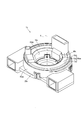
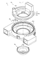
- the schematic perspective view of a rotation connector apparatus The schematic exploded perspective view of a rotation connector apparatus.
- the schematic exploded perspective view of a stator The schematic plan view of a stator main body. Explanatory drawing about an uneven
- the schematic perspective view of a rotation connector apparatus The schematic exploded perspective view of a rotation connector apparatus.
- FIG. 1 is a schematic perspective view of a rotary connector device 1 (steering roll connector, hereinafter referred to as SRC1) seen from above
- FIG. 2 is a schematic exploded perspective view of SRC1 seen from above
- FIG. 3 is a stator seen from above 20 is a schematic exploded perspective view
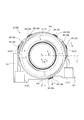
- FIG. 4 is a schematic plan view of the stator main body 21.
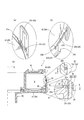
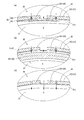
- FIG. 5 shows an explanatory diagram of the concave / convex fitting portion 25. More specifically, FIG. 5A shows a schematic perspective view around the body-side fitting recess 251 in which the ⁇ portion in FIG. 3 is enlarged, and FIG. 5B is a sub-side fitting corresponding to FIG.
- FIG. 5C is a schematic perspective view of the periphery of the joint convex portion 252 as viewed from below the inside of the diameter.
- FIG. 5C is a schematic sectional view of the SRC 1 along the line AA in FIG. And the enlarged view of the uneven
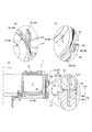
- FIG. 6 shows an explanatory diagram of the cable fixing portion 26. More specifically, FIG. 6A shows a schematic perspective view of the periphery of the main body-side fixing recess 261 when the portion ⁇ in FIG. 3 is viewed from the upper inside of the diameter, and FIG. 6B corresponds to FIG. FIG. 6C is a schematic perspective view of the periphery of the sub-side fixing recess 262 as viewed from the lower inside of the diameter, and FIG. 6C is a schematic cross-sectional view of SRC1 along the line BB in FIG. FIG.
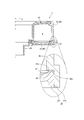
- FIG. 7 shows a schematic cross-sectional view of the polymerization protrusion 27. More specifically, FIG. 7 shows an enlarged view of the vicinity of the superposed protrusion 27 in the cross-sectional view along with a schematic cross-sectional view of SRC1 taken along the line CC in FIG.
- FIG. 8 shows an explanatory view of the vicinity of the stator locking portion 23. More specifically, FIG. 8A shows a schematic cross-sectional view taken along the line DD in FIG. 5C in the vicinity of the stator locking portion 23 of the present embodiment provided with the concave-convex fitting portion 25, and FIG. FIG. 8B is a schematic cross-sectional view taken along the line EE in FIG. 6C in the vicinity of the stator locking portion 23 of the present embodiment provided with the cable fixing portion 26, and FIG. FIG. 6 is a schematic cross-sectional view taken along the line DD in FIG. 5C in the vicinity of the stator locking portion 23 when not provided.
- FIG. 2 shows a state in which the winding portion Fr of the flat cable F is transmitted.
- FIG. 3 shows one end side extending to the rotator-side connector 13 in addition to the stator main body 21 and the sub-stator 22 constituting the stator 20.
- the flat cable F which abbreviate
- the rotator 10 side is the upper side and the sleeve 30 side is the lower side.
- the clockwise direction is the clockwise direction
- the counterclockwise direction is the counterclockwise direction.
- the SRC 1 of the present invention is fixed to a rotator 10 that follows the steering of a steering wheel (not shown), a stator 20 that is fixed to a steering column (not shown), and the rotator 10.
- the sleeve 30 is assembled along the central axis X in this order.
- the SRC 1 has a rotator 10 and a sleeve 30 that are assembled to the stator 20 so as to be relatively rotatable in both the clockwise and counterclockwise directions around the central axis X as a rotation center.
- the flat cable F is accommodated in the annular accommodation space S.
- the rotator 10 includes a top plate portion 11 that forms the upper surface of the SRC 1 and an inner peripheral portion 12 that forms the inner peripheral surface, and projects upward from the upper surface of the top plate portion 11.
- a rotator side connector 13 is provided.
- the top plate portion 11 constituting the rotator 10 is formed in a substantially flat annular shape, and the inner peripheral portion 12 is a cylindrical shape extending downward from the inner peripheral edge of the top plate portion 11.
- the rotator side connector 13 accommodates a connector component (not shown) connected to one end of the flat cable F, and a wire harness connector (not shown) connected to an electrical circuit of an auxiliary machine mounted on the steering wheel. And are electrically connected.
- the sleeve 30 is formed in a substantially cylindrical shape, is disposed on the opposite side of the rotator 10 with respect to the stator 20, and is fixed to the rotator 10 from below so as to sandwich the stator 20.
- the rotator 10 and the sleeve 30 configured as described above are assembled so as to be rotatable relative to the stator 20.
- the flat cable F housed in the housing space S has one end connected to the connector constituting part housed in the rotator-side connector 13 and the other end connected to the connector Fc fixed to the stator 20 as shown in FIG. Thus, a winding portion Fr that is housed in the housing space S is wound between these.
- two such flat cables F are used, and are configured to overlap with two dummy flat cables.
- the connector Fc is fitted and electrically connected to a wire harness connector (not shown) arranged on the steering column side.
- a wire harness connector not shown
- the flat cable F configured as described above has a folded portion Fu formed by folding the other end side to which the connector Fc is connected.
- the stator 20 fixed to the steering column will be described in detail with reference to FIGS.
- the stator 20 is configured by assembling a stator main body 21 that configures the lower surface of the SRC 1 and a sub-stator 22 that configures the outer peripheral surface, and the assembled state is held by the stator locking portion 23. ing.
- the stator 20 has a facing portion 24 in which the stator main body 21 and the sub-stator 22 face each other mainly in the vertical direction (rotation axis X direction) in the assembled state, and foreign matter intrusion that suppresses intrusion of foreign matter into the accommodation space S is achieved.
- a concavity and convexity fitting portion 25 that functions as a means and a cable fixing portion 26 that fixes a folded portion Fu that functions as a foreign matter intrusion restricting means are formed in the facing portion 24, and the stator body 21 and the sub-stator 22 are superposed in the radial direction.
- a protruding portion 27 is provided.
- the stator body 21 constituting the stator 20 is formed in a substantially annular plate shape, and includes a lower cover portion 211 that covers the lower side of the connector Fc, and a frame-like locking portion 231 described later.
- the main body side fitting recess 251, the main body side fixing recess 261, and the main body side protrusion 271 are provided.
- a portion slightly protruding upward from the upper surface of the outer peripheral edge of the stator body 21 is defined as an outer peripheral edge portion 21a.
- the lower cover portion 211 is formed so as to protrude from the stator main body 21 so as to cover the lower portions of the connectors Fc arranged in both the left and right directions on the front side of the SRC 1.
- the sub-stator 22 has a cylindrical shape extending upward from the outer peripheral edge portion 21 a of the stator body 21, and surrounds the upper cover portion 221 that covers the upper side of the connector Fc and the stator locking portion 23.
- the lower surface 22a of the sub-stator 22 faces the outer peripheral edge 21a in the up-down direction (center axis X direction) when the stator 20 is assembled.
- the upper cover portion 221 faces the lower cover portion 211 in the vertical direction (center axis X direction), and is formed to protrude from the stator main body 21 so as to cover the upper portion of each connector Fc.
- the surrounding portion 222 is formed so as to surround the periphery of the sub-stator 22 around a frame-like engaging portion 231 of the stator engaging portion 23 described later. More specifically, the surrounding portion 222 has a frame shape with respect to the outer diameter of the frame-shaped locking portion 231 on the inner side in the circumferential direction, and the upper portion excluding the upper center of the frame-shaped locking portion 231 and both sides in the circumferential direction. Surrounds three directions. In other words, the surrounding portion 222 is formed in an inverted L shape and is arranged in a symmetrical shape in the circumferential direction with the stator locking portion 23 interposed therebetween.
- the stator locking portion 23 that holds the assembled state of the stator 20 is erected upward from the outer peripheral edge of the stator main body 21, and is substantially rectangular frame-shaped locking as viewed from the outside of the diameter.
- the portion 231 and a protruding locking portion 232 that protrudes radially outward from the outer peripheral surface of the sub-stator 22 are configured to be lockable.
- the stator locking portion 23 is counterclockwise from the imaginary line Z with the imaginary line Z extending rightward from the central axis X as 0 degrees and the central axis X as the rotation center in the plan view of the stator body 21 shown in FIG. In the direction, a total of five positions are arranged at a position of about 20 degrees, a position of about 60 degrees, a position of about 120 degrees, a position of about 160 degrees, and a position of about 290 degrees.
- the stator locking portion 23 configured as described above is a state in which the stator 20 is assembled so that a body-side fitting concave portion 251 and a sub-side fitting convex portion 252 described later are in contact with each other. 2, the frame-shaped locking part 231 and the protruding locking part 232 are arranged with a slight gap L1 in the vertical direction (the direction of the central axis X). As a result, the frame-shaped locking portion 231 and the protruding locking portion 232 can be easily locked and unlocked.
- the facing portion 24 facing in the up-down direction is composed of an outer peripheral edge portion 21 a of the stator body 21 and a lower surface 22 a of the sub-stator 22.
- a concave / convex fitting portion 25 for concave / convex fitting the peripheral edge portion 21a and the lower surface 22a and a cable fixing portion 26 for fixing the folded portion Fu of the flat cable F are formed.
- the concave / convex fitting portion 25 functioning as a foreign matter intrusion suppressing means is a concave body-side fitting concave portion 251 in which the outer peripheral edge portion 21a of the stator main body 21 is recessed. And the convex sub side fitting convex part 252 which protruded the lower surface 22a of the sub stator 22 is comprised so that uneven
- the main body-side fitting recess 251 has a width about half that of the outer peripheral edge 21a in the outer peripheral edge 21a on the inner diameter side of the frame-shaped locking part 231, and is slightly longer than the circumferential length of the frame-shaped locking part 231. It is formed in a groove shape recessed in a concave shape at a predetermined depth. Note that the predetermined depth is the fitting length L2, and the fitting length L2 is longer than the interval L1 between the frame-like locking portion 231 and the protruding locking portion 232 (L1 ⁇ L2).
- the sub-side fitting convex portion 252 that fits with the main body side fitting concave portion 251 protrudes toward the main body side fitting convex portion 261 by a fitting length L2, and has a convex shape corresponding to the main body side fitting concave portion 251. It is formed, and both ends in the circumferential direction are connected to a sub-side protrusion 272 of the overlapping protrusion 27 described later.
- the main body side fitting concave portion 251 and the sub side fitting convex portion 252 are arranged on the outer diameter side of the facing portion 24 corresponding to the frame-like locking portion 231. That is, the concave / convex fitting portion 25 formed by the main body side fitting concave portion 251 and the sub-side fitting convex portion 252 has a radially inner side and a radially outer side in the opposed portion 24 in the vertical direction (center axis X) in the assembled state of the stator 20. Direction) and the fitting length L2 is different.
- the facing portion 24 corresponding to the concave-convex fitting portion 25 is refracted in a stepped shape so that the inner diameter side is positioned higher than the outer diameter side by a fitting length L2 from the substantially radial center.
- the length in the radial cross section of the facing portion 24 corresponding to the concave / convex fitting portion 25 is the vertical length (center) opposed to the radial direction to the radial length facing the vertical direction (center axis X direction).
- the concave / convex fitting portion 25 configured as described above has a position of about 60 degrees, a position of about 120 degrees in the counterclockwise direction from the imaginary line Z around the center axis X, and It is arranged at each of the positions of about 290 degrees.
- the cable fixing portion 26 that fixes the folded-back portion Fu that functions as a foreign matter intrusion suppressing means is a concave main body in which the outer peripheral edge portion 21a of the stator main body 21 is recessed.
- the side fixing recess 261 and a concave sub-side fixing recess 262 in which the lower surface 22a of the sub-stator 22 is recessed are configured.
- each of the fixed recesses 261 and 262 is formed in a rectangular shape in the radial cross section, and the width of the folded portion Fu of the flat cable F, that is, the thickness of the two flat cables F, It is formed in the same width.
- These fixed recesses 261 and 262 are respectively formed along the circumferential direction, and are similarly formed at positions facing each other in the assembled state of the stator 20, so that the main body side fixed recess 261 will be described in detail below. A detailed description of the sub-side fixing recess 262 will be omitted.
- the main body-side fixing recess 261 is positioned about 45 degrees counterclockwise from the imaginary line Z around the central axis X from the lower cover portion 211 on the right side formed in the stator main body 21.
- the main body side fixing recess 261 formed on the left side is formed in a substantially bilaterally symmetric shape with the right main body side fixing recess 261.
- each main body-side fixing recess 261 is formed so as to straddle the frame-shaped locking portion 231 disposed at a position of about 20 degrees or a position of about 160 degrees, and the base end side is formed on each lower cover section 211.
- the cable fixing portion 26 is the folded portion Fu so as to straddle the frame-shaped locking portion 231 disposed at a position of about 20 degrees or a position of about 160 degrees in the assembled state of the flat cable F and the stator 20. Can be fixed without sliding.
- the overlapping protruding portion 27 that overlaps in the radial direction protrudes downward from the main body side protruding portion 271 that protrudes downward from the outer peripheral edge of the stator main body 21 and the radially outer side of the lower end of the sub-stator 22.
- the sub-side protrusion 272 is configured.
- the main body side protruding portion 271 protrudes downward from the lower surface of the outer peripheral edge of the stator main body 21 and is formed on the entire circumference of the stator main body 21.
- the sub-side protruding portion 272 protrudes radially outward from the lower end of the sub-stator 22 and has a substantially L-shaped radial cross section protruding downward, and is formed over the entire circumference of the sub-stator 22.
- the sub-side protruding portion 272 is disposed on the outer diameter side of the facing portion 24. Further, as shown in FIG. 5B and FIG. 6B, the sub-side protruding portion 272 is formed with a notch portion 273 in which a portion corresponding to the frame-like locking portion 231 is notched.
- the frame-like engagement portion 231 constituting the stator engagement portion 23 is notched.
- the assembled state is maintained by passing through the portion 273 and locking with the protruding locking portion 232.
- the concave / convex fitting portion 25 is provided, the folded portion Fu is fixed to the cable fixing portion 26, and the concave / convex fitting portion 25 and the folded portion Fu are connected to the stator body 21.
- the stator locking portion 23 By disposing at a position corresponding to the stator locking portion 23 in the portion 24 facing the sub-stator 22, foreign matter such as dust, dust, or fine sand is passed through the portion corresponding to the stator locking portion 23 in the facing portion 24. Intrusion into the accommodation space S can be suppressed.
- the overlapping protrusion 27 is provided over the entire circumference of the stator 20 except for the frame-like locking portion 231.
- a cutout portion 273 is provided at a portion corresponding to the frame-shaped locking portion 231 in the main body-side protruding portion 271, and the frame-shaped locking portion 231 is formed at the facing portion 24 as indicated by an arrow in FIG.
- the foreign matter may enter the housing space S through the notch 273 corresponding to the (stator locking portion 23).
- the facing portion 24 in the radial cross section is simply in the vertical direction in the portion corresponding to the notch portion 273. Not only is the length increased compared to the conventional facing portion that faces only in the (center axis X direction), but it is also refracted in a stepped shape in the vertical direction (center axis X direction), and the sub-side fitting convex portion 252 is connected to the sub-side protrusion 272.
- the intrusion path through which the foreign substance enters the accommodation space S from the outside can be refracted and extended in the radial cross section, and a portion corresponding to the notch 273 is represented by an arrow in FIG. It can be regulated in the radial direction.
- the folded portion Fu is fixed to the cable fixing portion 26 in such a manner as to straddle the stator locking portion 23 in the circumferential direction and the opposing portion 24 in the vertical direction (center axis X direction).
- the entry path of the foreign matter can be reliably blocked as shown by the arrow in FIG.
- the facing portion 24 is more than the conventional SRC 1 in which the concave / convex fitting portion 25 and the turn-back portion Fu are not provided in the portion corresponding to the stator locking portion 23 in the facing portion 24, that is, the portion corresponding to the notch 273. It is possible to prevent the foreign matter from entering the housing space S through the portion corresponding to the stator locking portion 23.
- main body side fitting concave portion 251 and the sub side fitting convex portion 252 that are concavo-convexly fitted can also function as an alignment portion when the stator main body 21 and the sub stator 22 are assembled, and furthermore, in the assembled state. Assembling strength can be improved, and a stable assembled state between the stator main body 21 and the sub-stator 22 can be obtained.
- corrugated fitting part 25 is arrange
- the entry of the foreign matter into the accommodation space S can be suppressed also by gravity at a portion facing the radial direction at a substantially central portion in the radial direction at 24. Therefore, the entry of the foreign matter into the accommodation space S can be more reliably suppressed.
- the main body side fitting concave portion 251 and the sub side fitting convex portion 251 are in contact with the main body side fitting concave portion 251 and the sub side fitting convex portion 252 in the vertical direction (center axis X direction).
- the fitting length L2 to be fitted with 252 longer than the interval L1 between the frame-like locking portion 231 and the protruding locking portion 232 in the vertical direction (center axis X direction) (L1 ⁇ L2) Intrusion of the foreign matter into the accommodation space S can be further reliably suppressed.
- the main body side fitting recess 251 and the sub-side fitting projection 252 are separated by an interval L1 between the frame-like locking portion 231 and the protruding locking portion 232 (center axis) due to the assembly variation of the SRC1. Even when spaced apart in the X direction), the gap formed in the facing portion 24 is not formed so as to penetrate in the radial direction toward the accommodation space S, and a stepped shape is maintained. Thereby, the penetration
- the folded portion Fu of the flat cable F which is one of the components of the SRC 1 is fixed to the cable fixing portion 26 and used as a blocking member, so that the foreign substance intrusion path is blocked. There is no need to use a member, and the number of parts constituting the SRC 1 can be reduced and the weight can be reduced.
- the sub-stator 22 is provided with the surrounding portion 222 that surrounds the periphery of the frame-like locking portion 231 along the outer peripheral surface, thereby preventing the foreign matter from entering the accommodation space S more reliably. can do.
- the surrounding portion 222 can prevent the foreign matter from approaching the facing portion 24 through the space between the outer peripheral surface of the sub-stator 22 and the frame-like locking portion 231, so that the facing portion 24 moves into the housing space S. It is possible to reduce the amount of the foreign matter that tries to enter.
- the concave / convex fitting portion 25 provided in the facing portion 24 or the folded portion Fu fixed to the cable fixing portion 26 tries to enter the accommodation space S. Since entry of the foreign matter can be suppressed, entry of the foreign matter into the accommodation space S can be more reliably prevented.
- the rotary connector device of the present invention corresponds to the SRC1 of the embodiment
- the rotating body corresponds to the rotator 10
- the rotation side ring plate corresponds to the top plate part 11
- the inner peripheral cylinder portion corresponds to the inner peripheral portion 12
- the fixed body corresponds to the stator 20
- the fixed side ring plate corresponds to the stator body 21
- the outer peripheral cylinder portion corresponds to the sub-stator 22
- the locking means corresponds to the stator locking portion 23
- the locking part corresponds to the frame-shaped locking part 231
- the locked portion corresponds to the protruding locking portion 232
- the foreign matter intrusion restricting means corresponds to the concave / convex fitting portion 25
- the fitting recess corresponds to the body-side fitting recess 251
- the fitting projection corresponds to the sub-side fitting projection 252;
- the fixing recesses correspond to the cable fixing portion 26, the main body side fixing recess 261 and the sub-side fixing recess 262,
- the main body side fitting concave portion 251 formed in the stator main body 21 and the sub side fitting convex portion 252 formed in the sub stator 22 constitute not only the concave and convex fitting portion 25, but also FIG.
- FIG. 9 shows an explanatory view of the concave / convex fitting portion 25a configured by the main body side fitting convex portion 251a and the sub-side fitting concave portion 252a. More specifically, FIG. 9 shows a schematic cross-sectional view of the SRC 1 along the line BB in FIG. 4 and an enlarged view around the concave-convex fitting portion 25a in the cross-sectional view.
- the radial length in the radial section of the facing portion 24a corresponding to the concave and convex fitting portions 25 and 25a is larger than the plate thickness of the sub-stator 22 as shown in FIG.
- the plate thickness on the lower end side of the sub-stator 22 may be set so as to be longer.
- main body side fitting concave portion 251 and the sub side fitting convex portion 252 are not only formed in a rectangular shape, but may be formed in a curved shape as long as they can be engaged with each other. You may combine curvilinear form.
- a synthetic resin plate-like body may be fixed, or silicon or rubber packing or grease may be attached to the facing portion 24. It may be interposed.
- FIGS. 10 shows a schematic perspective view of the rotary connector device 1x (steering roll connector, hereinafter referred to as SRC1x) seen from above
- FIG. 11 shows a schematic exploded perspective view of SRC1x seen from above
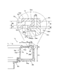
- FIG. 12 shows a single cross section of SRC1x
- an enlarged view of the periphery of the outer peripheral edge portion 13x and the upper end portion 22x in the cross-sectional view is shown.
- FIGS. 12 and 13 illustrate the SRC 1x in which the left side from the central axis X is omitted.
- the rotator 10x side is an upper side and the sleeve 30x side is a lower side.
- the clockwise direction is the clockwise direction
- the counterclockwise direction is the counterclockwise direction.
- the SRC 1x of the present invention is fixed to a rotator 10x that follows the steering of a steering wheel (not shown), a stator 20x that is fixed to a steering column (not shown), and the rotator 10x.
- the sleeve 30x is assembled along the central axis X in this order.
- the SRC 1x has a rotator 10x and a sleeve 30x that are assembled to the stator 20x so as to be relatively rotatable in both a clockwise direction and a counterclockwise direction with the central axis X as a rotation center.
- the flat cable Fx wound around the annular accommodation space Sx is accommodated.
- the rotator 10x is a ring that forms the upper surface of the SRC 1x, and has a substantially flat top plate portion 10xa and projects downward from the inner edge of the top plate portion 10xa to form the inner peripheral surface of the SRC 1x.
- the substantially cylindrical inner peripheral portion 10xb is integrally formed.
- the top plate portion 10xa constituting the rotator 10x has an outer diameter that is slightly smaller than an outer peripheral portion 20xb of the stator 20x, which will be described later, and an inner peripheral edge from the inner diameter to the outer diameter.
- the portion 11x, the top plate portion main body 12x, and the outer peripheral edge portion 13x are arranged in this order.
- the top plate main body 12x is formed in a substantially flat plate shape, and the inner peripheral edge portion 11x is formed in a tapered cross section having an inclined surface 11xa inclined downward inward in the radial direction.
- the outer peripheral edge portion 13x is formed in an annular flat plate whose lower surface substantially coincides with the upper surface of the top plate body 12x, and has a rotator side protruding portion 13xa protruding downward and protruding downward.
- the connecting portion 13xb that connects to the outer edge of the top plate main body 12x is provided on the inner edge. That is, the outer peripheral edge portion 13x is formed in a substantially concave shape protruding upward by the rotator side protruding portion 13xa and the connecting portion 13xb.
- the radial length of the outer peripheral edge portion 13x is formed to be about twice the radial length of the inner peripheral edge portion 11x and the top plate main body 12x.
- the rotator-side protruding portion 13xa protrudes downward by a predetermined length, the lower tip is formed in a circular arc shape in cross section, and an annular substantially cylindrical body formed on the entire circumference of the tip of the outer peripheral edge portion 13x. It is.
- predetermined length be protrusion length H1.
- the top plate portion 10xa configured as described above has a radially outer portion of the top plate portion main body 12x and a connecting portion 13a of the outer peripheral edge portion 13x connected in the radial direction, and the lower surface of the connecting portion is cut into a substantially rectangular shape.
- a notched portion 14x is formed.
- the cutout portion 14x has a radial length equivalent to the plate thickness of the connecting portion 13xb, and the cutout amount is about half of the plate thickness of the top plate body 12x.
- the stator 20x is a substantially cylindrical bottom plate portion 20xa that is a ring that forms the lower surface of the SRC 1x, and a substantially cylindrical shape that protrudes upward from the outer edge of the bottom plate portion 20xa and constitutes the outer peripheral surface of the SRC 1x. And an outer peripheral portion 20xb.
- the outer peripheral portion 20xb constituting the stator 20x is configured by disposing an outer peripheral portion main body 21x and an upper end portion 22x from the lower side to the upper side, and protrudes radially inward from the lower side of the upper end portion 22x. It has a ring-shaped projecting ring portion 23x that is a substantially flat plate shape. In other words, in the outer peripheral portion 20xb, the upper end portion 22x is located above the protruding annular portion 23x.
- the outer peripheral portion main body 21x is a cylindrical body that extends upward from the outer edge of the bottom plate portion 20xa and is formed with a predetermined plate thickness. Thereby, the outer peripheral part main body 21x can have fixed intensity
- the upper end portion 22x is a cylindrical body having an outer diameter that is the same as the outer diameter of the outer peripheral portion main body 21x and a thickness of about two-thirds of the outer peripheral portion main body 21x.
- the upper end portion 22x is formed so that the top portion substantially coincides with the upper surface of the top plate portion 10xa in the assembled state of the SRC 1x.
- the upper end portion 22x formed to have a plate thickness of about two-thirds of the outer peripheral portion main body 21x can be provided with a gap D3 between the upper end portion 22x and the rotator side protruding portion 13xa in the assembled state of the SRC 1x.
- the relative rotation of the rotator 10x with respect to can be performed smoothly, and the weight of the stator 20x can be reduced.
- the protruding annular portion 23x is formed in a tapered shape having an inclined surface 23xa that is inclined upward toward the inside of the diameter, and is provided with a stator side protruding portion 23xb that protrudes slightly upward from the outside of the diameter toward the upper side. It has been.
- the tip of the protruding annular portion 23x is slightly inward of the stator-side protruding portion 23xb so as to be spaced in the radial direction from the radially inner surface of the notch portion 14x in the assembled state of the SRC 1x. Protruding. Note that the distance D4 between the tip of the projecting ring part 23x and the radially inner surface of the notch part 14x is wider than the distance D3 between the upper end part 22x and the rotator side projecting part 13xa (D3 ⁇ D4).
- the stator-side protruding portion 23xb has a protruding length H2 protruding upward that is shorter than the protruding length H1 of the rotator-side protruding portion 13xa (H1> H2), and is formed on the entire circumference on the tip side of the protruding annular portion 23x. It is an annular substantially cylindrical body. Note that the radial distance D5 between the stator-side protrusion 23xb and the coupling part 13xb in the assembled state of the SRC 1x is wider than the distance D3 between the upper end 22x and the rotator-side protrusion 13xa (D3 ⁇ D5).
- the sleeve 30x is formed in a substantially cylindrical shape, is disposed on the opposite side of the rotator 10x with respect to the stator 20x, and is fixed to the rotator 10x from below so as to sandwich the stator 20x.
- the upper surface of the protruding annular portion 23x faces the lower surface of the outer peripheral edge portion 13x in parallel.
- upper end part 22x, rotator side protrusion part 13xa, and stator side protrusion part 23xb are arrange
- the rotator-side protruding portion 13xa faces the substantially radial center of the protruding annular portion 23x
- the stator-side protruding portion 23xb faces the substantially radial center of the outer peripheral edge portion 13x.
- the facing distance D1 between the rotator-side protruding portion 13xa and the protruding annular portion 23x is shorter than the facing distance D2 between the stator-side protruding portion 23xb and the outer peripheral edge portion 13x. That is, the tip of the rotator side protrusion 13xa is lower than the top of the upper end 22x and the tip of the stator side protrusion 23xb between the outer peripheral edge portion 13x and the protruding annular portion 23x arranged in parallel in the vertical direction. Protruding.
- the distance D3 between the rotator-side protruding portion 13xa and the upper end portion 22x is larger than the distance D4 between the radially inner end portion of the protruding annular portion 23x and the radially inner surface of the notch portion 14x.
- the upper end portion 22x, the rotator side protruding portion 13xa, and the stator side protruding portion 23xb are arranged in this order from the radially outer side to the radially inner side, and the tip is the upper end portion 22x and the stator side protruding portion.
- the size is increased by providing the rotator side protrusion 13xa that protrudes downward from the tip of 23xb and has a protrusion length H1 longer than the protrusion length H2 of the stator side protrusion 23xb (H1> H2). Without entry, foreign matter such as dust and dirt can be prevented from entering the storage space Sx.
- the entry path of the foreign matter entering the storage space Sx from the outside is In order to bend in a substantially U shape so as to extend downward between the upper end 22x and the rotator side protrusion 13xa and to extend upward between the rotator side protrusion 13xa and the stator side protrusion 23xb (in FIG. 12) ), The foreign matter can be prevented from directly entering the accommodation space Sx along the radial direction.
- the upper end portion 22x is disposed outside the gap between the rotator side protrusion 13xa and the protrusion ring portion 23x, the amount of the foreign matter reaching the rotator side protrusion 13xa can be reduced. Further, even when the foreign matter reaches the rotator side protrusion 13xa, the protrusion length H1 of the rotator side protrusion 13xa is longer than the protrusion length H2 of the stator side protrusion 23xb. The foreign matter that enters the accommodation space Sx from the protruding portion 13xa can be restricted.
- the outer peripheral portion 20xb is not a conventional two-layer structure but a one-layer structure, so that the SRC 1x can be prevented from entering the accommodation space Sx without being enlarged in the radial direction. it can.
- the protruding length H1 of the rotator side protruding portion 13xa is set to the protruding length H2 of the stator side protruding portion 23xb. Therefore, the rotator-side protruding portion 13xa comes into contact with the protruding annular portion 23x before the stator-side protruding portion 23xb comes into contact with the outer peripheral edge portion 13x.
- the position where the rotator-side protrusion 13xa abuts in the protruding ring portion 23x is the base end side where the amount of deflection is smaller than the position where the stator-side protrusion 23xb is disposed in the protruding ring portion 23x.
- the former has a larger protruding amount of deflection.
- the protrusion length H1 of the rotator side protrusion 13xa is set so that the rotator side protrusion 13xa contacts the protrusion ring portion 23x before the stator side protrusion 23xb contacts the outer peripheral edge portion 13x.
- the stator side protrusion 23xb is longer than the protrusion length H2 (H1> H2).
- the SRC 1x according to the present embodiment can not only increase the size of the SRC 1x but also prevent the foreign matter from entering the housing space Sx, and can also suppress the generation of the abnormal noise due to contact. Can do.
- the top of the outer peripheral portion 20xb at a height that is approximately the same as the top plate portion 10xa, it is possible to reliably control the foreign matter that enters the accommodation space Sx from the radial direction, and the SRC 1x It is possible to prevent the relative rotational performance from being lowered.
- the top of the outer peripheral portion 20xb formed at the same height as the top plate portion 10xa does not protrude upward from the top plate portion 10xa, so that the top portion of the outer peripheral portion 20xb in the stator 20x fixed to the steering column is It is possible to prevent interference with the steering wheel that is rotated.
- the outer periphery formed at a height that is approximately the same as the top plate portion 10xa.
- the portion 20xb can prevent the rotator-side protruding portion 13xa from jumping out and interfering with the upper end portion 22x beyond the diameter.
- the outer peripheral portion 20xb formed with the top portion having the same height as the top plate portion 10xa can surely restrict the entry of the foreign matter from the outside of the diameter into the accommodation space Sx rather than the upper end portion 22x.
- the SRC 1x of the present embodiment can surely regulate the foreign matter that enters the accommodation space Sx from the radial direction, and can prevent a decrease in relative rotational performance.
- the projecting annular portion 23x is formed in a tapered shape that is gradually thinned toward the tip, so that the projecting annular portion 23x is easily bent toward the tip.
- the protruding annular portion 23x that is pressed in contact with the protruding portion 13xa can reduce contact resistance by bending due to the pressing force.
- the lower end of the rotator-side protrusion 13xa is formed in a circular arc shape so that the rotator-side protrusion 13xa and the protrusion ring portion 23x are in the radial direction even if they are in contact with each other. Since the cross section is in a point contact state, the contact resistance can be reliably reduced. Therefore, it can prevent more reliably that the relative rotational performance of SRC1x falls.
- the notch portion 14x is formed on the lower surface of the connecting portion between the top plate main body 12x and the outer peripheral edge portion 13x, so that even if the protruding annular portion 23x is bent, the stator side protrusion It can prevent that the front-end
- the distance D3 between the rotator-side protruding portion 13xa and the upper end portion 22x is based on the distance D4 between the radially inner end portion of the protruding annular portion 23x and the radially inner surface of the notch portion 14x. Is also narrower (D3 ⁇ D4), and is narrower than the interval D5 between the stator side protrusion 23xb and the connecting portion 13xb (D3 ⁇ D5).
- the diameter slope 11a of the inner peripheral edge portion 11x is inclined upward toward the radially outer side, so that the inner diameter of the flat cable Fx that is tightened or unwound along with the relative rotation of the SRC 1x. Can be guided from the outside of the flat cable Fx to the outside of the flat cable Fx relative to the relative rotation of the SRC 1x. Inward movement can be guided.
- the inclined surface 23xa of the projecting annular portion 23x that guides the movement of the flat cable Fx also prevents the flat cable Fx from entering the gap between the projecting annular portion 23x that rotates relative to the outer peripheral edge portion 13x. Can do.
- the rotary connector device of the present invention corresponds to the SRC1x of the embodiment
- the rotating body corresponds to the rotator 10x
- the rotation side ring plate corresponds to the top plate portion 10xa
- the inner peripheral cylinder part corresponds to the inner peripheral part 10b
- the rotation side protrusion corresponds to the rotator side protrusion 13xa
- the fixed body corresponds to the stator 20x
- the fixed ring plate corresponds to the bottom plate portion 20xa
- the outer cylinder part corresponds to the outer part 20xb
- the top side edge corresponds to the upper end 22x
- the protruding ring plate corresponds to the protruding annular portion 23x
- the fixed side protrusion corresponds to the stator side protrusion 23xb
- the protrusion length of the rotation side protrusion corresponds to the protrusion length H1
- the protrusion length of the fixed-side protrusion corresponds to the protrusion length H2
- the present invention is
- the radially inner surface of the cutout portion 14y formed on the lower surface of the connecting portion between the top plate main body 12y and the outer peripheral edge portion 13y may be shifted toward the central axis X. That is, the length in the radial direction of the cutout portion 14y may be extended inward in the radial direction as shown in FIG.
- the extending length can be appropriately set according to the ratio between the length in the vertical direction and the length in the radial direction of the accommodation space Sx.
- FIG. 13 shows an enlarged view of the periphery of the outer peripheral edge portion 13y and the upper end portion 22x in the cross-sectional view, along with a schematic cross-sectional view in one cross section of the SRC 1y in another embodiment.
- the length in the vertical direction and the length in the radial direction of the accommodation space Sx are substantially equal, whereas the other SRC 1y shown in FIG.
- the length in the radial direction is longer than the length in the vertical direction of the accommodation space Sx, the amount by which the rotator 10y is relatively inclined with respect to the stator 20x or the rotator 10y and the stator 20x are relatively deformed. Will increase.
- by appropriately extending the length of the cutout portion 14y in the radial direction it is possible to prevent the tip of the protruding annular portion 23x and the top plate portion 10y from interfering with each other.
- the outer peripheral edge part 13x is connected with the upper surface of the top-plate part main body 12x, you may connect not only to this but the top-plate part main body 11c and flush.
- the top plate portion main body 12x may be coupled to the lower surface.
Landscapes
- Engineering & Computer Science (AREA)
- Mechanical Engineering (AREA)
- Chemical & Material Sciences (AREA)
- Combustion & Propulsion (AREA)
- Transportation (AREA)
- Connector Housings Or Holding Contact Members (AREA)
- Steering Controls (AREA)
- Electric Cable Arrangement Between Relatively Moving Parts (AREA)
Abstract
Description
前記遮断部は、例えば、前記固定側リング板と前記外周筒部との前記対向部分に形成した固定凹部に固定して、前記対向部分を径方向に遮断する固定遮断部材や、前記対向部分に密着するように介在させて、前記対向部分を径方向に遮断する密着遮断部材などを含む。なお、具体的な上記密着遮断部材として、例えばシリコン製やゴム製のパッキン、あるいはグリスなどを含む。
この発明により、前記収容空間への前記異物の侵入経路を確実に遮断して、前記収容空間への前記異物の侵入を確実に防止することができる。
この発明により、前記固定遮断部材として別部材を用いる必要がなく、前記回転コネクタ装置を構成する部品点数を削減し軽量化することができる。
この発明により、前記収容空間への前記異物の侵入をより確実に防止することができる。
この発明により、回転コネクタ装置を大型化することなく、収容空間への塵や埃などの異物の侵入を防止することができる。
このような前記回転側突出部、前記突出リング板および前記固定側突出部を備えたことによって、前記収容空間への上記異物の侵入を防止することができる。
このとき、前記突出リング板における前記回転側突出部が当接する位置は、前記突出リング板における前記固定側突出部の配置位置よりも撓み量が小さい基端側となる。
この発明により、径方向から前記収容空間へ侵入する上記異物を確実に規制できるとともに、前記回転コネクタ装置の相対回転性能が低下することを防止できる。
上述したように本発明の回転コネクタ装置は、径方向から前記収容空間へ侵入する上記異物を確実に規制できるとともに、相対回転性能の低下を防止することができる。
この発明により、先端に向けて前記突出リング板は撓み易くなるため、前記回転側突出部と当接して押圧される前記突出リング板は、押圧力による撓みによって接触抵抗を低減することができる。
この発明により、前記回転側突出部と前記突出リング板とは、仮に接触した場合であっても軸方向に沿う径方向断面において点接触状態となるため、接触抵抗を確実に低減することができる。したがって、前記回転コネクタ装置の相対回転性能が低下することをより確実に防止できる。
図1は上方からみた回転コネクタ装置1(ステアリングロールコネクタ、以下においてSRC1とする)の概略斜視図を示し、図2は上方からみたSRC1の概略分解斜視図を示し、図3は上方からみたステータ20の概略分解斜視図を示し、図4はステータ本体21の概略平面図を示している。
まず、ステータ20に対して相対回転するロテータ10、スリーブ30、およびフラットケーブルFについて、図2および図3を用いて簡単に説明する。
ロテータ側コネクタ13は、フラットケーブルFの一端に接続されたコネクタ構成部(図示省略)を収容し、上記ステアリングホイールに搭載される補機の電気回路に接続されたワイヤハーネスのコネクタ(図示省略)と嵌合して電気的に接続される。
上述のように構成したロテータ10とスリーブ30とは、ステータ20に対して相対回転自在に組み付けられる。
このようなフラットケーブルFを本実施形態では2本使用し、2本のダミーフラットケーブルとともに重ね合わせて構成されている。
以上のように構成するフラットケーブルFには、図3に示すように、コネクタFcを接続した他端側を折り返して重ね合わせた折り返し部Fuが形成されている。
ステータ20は、図2および図3に示すように、SRC1の下面を構成するステータ本体21と、外周面を構成するサブステータ22とを組み付けて構成され、組み付け状態をステータ係止部23によって保持されている。
下方カバー部211は、SRC1の正面側における左右の両方向に配置したコネクタFcの下方をそれぞれカバーするように、ステータ本体21から突出形成されている。
上方カバー部221は、下方カバー部211と上下方向(中心軸X方向)に対向しており、各コネクタFcの上方をカバーするように、ステータ本体21から突出形成されている。
詳述すると、囲繞部222は、周方向における内側が枠状係止部231の外径に対する枠型であり、枠状係止部231の上方中央を除く上部と、周方向の両側部との3方向を囲繞している。換言すると、囲繞部222は、逆L字状に形成されるとともに、ステータ係止部23を挟んで周方向に左右対称形状に配置されている。
つまり、本体側嵌合凹部251およびサブ側嵌合凸部252で構成する凹凸嵌合部25は、ステータ20の組み付け状態において、対向部分24における径内側と径外側とが上下方向(中心軸X方向)に嵌合長さL2分段違いとなる。
したがって、ケーブル固定部26は、フラットケーブルFとステータ20との組み付け状態において、約20度の位置または約160度の位置に配置した枠状係止部231を周方向に跨ぐように折り返し部Fuを摺動することなく固定することができる。
また、このサブ側突出部272は、図5(b)や図6(b)に示すように、枠状係止部231に対応する部分を切り欠いた切り欠き部273が形成されている。
したがって、収容空間Sへの上記異物の侵入をより確実に抑制することができる。
この発明の回転コネクタ装置は、実施形態のSRC1に対応し、
以下同様に、
回転体は、ロテータ10に対応し、
回転側リング板は、天板部11に対応し、
内周筒部は、内周部12に対応し、
固定体は、ステータ20に対応し、
固定側リング板は、ステータ本体21に対応し、
外周筒部は、サブステータ22に対応し、
係止手段は、ステータ係止部23に対応し、
係止部は、枠状係止部231に対応し、
被係止部は、突出係止部232に対応し、
異物侵入規制手段は、凹凸嵌合部25に対応し、
嵌合凹部は、本体側嵌合凹部251に対応し、
嵌合凸部は、サブ側嵌合凸部252に対応し、
固定凹部は、ケーブル固定部26、本体側固定凹部261およびサブ側固定凹部262に対応し、
係止部と被係止部との軸方向の間隔は、間隔L1に対応し、
嵌合凸部と嵌合凹部との軸方向に嵌合する長さは、嵌合長さL2に対応し、
異物侵入規制手段、遮断部および固定遮断部材は、折り返し部Fuに対応するが、
この発明は、上述の実施形態の構成のみに限定されるものではなく、多くの実施の形態を得ることができる。
図10は上方からみた回転コネクタ装置1x(ステアリングロールコネクタ、以下においてSRC1xとする)の概略斜視図を示し、図11は上方からみたSRC1xの概略分解斜視図を示し、図12はSRC1xの片断面における概略断面図とともに、当該断面図における外周縁部13xおよび上端部22x周辺の拡大図を示している。
また、本実施形態において、ステータ20xを基準として、ロテータ10x側を上方とし、スリーブ30x側を下方とする。また、上方からみたSRC1xにおいて、右回り方向を時計回り方向とするともに、左回り方向を反時計回り方向とする。
外周縁部13xは、下面が天板部本体12xの上面と略一致する円環の平板状に形成されており、下方に向けて突出するロテータ側突出部13xaを外縁に備えるとともに、下方に突出して天板部本体12xの外縁と連結する連結部13xbを内縁に備えている。つまり、外周縁部13xは、ロテータ側突出部13xaと連結部13xbとで、上方に突出する略凹状に形成されている。なお、外周縁部13xの径方向の長さは、内周縁部11xや天板部本体12xの径方向の長さの約2倍に形成されている。
切り欠き部14xは、径方向の長さが連結部13xbの板厚と同等で、切り欠き量が天板部本体12xの板厚の約半分である。
上端部22xは、外径が外周部本体21xの外径と同一であるとともに、外周部本体21xの3分の2程度の板厚に形成された筒状体である。
なお、外周部本体21xの3分の2程度の板厚に形成された上端部22xは、SRC1xの組み付け状態において、ロテータ側突出部13xaとの間に間隔D3を設けることができるため、ステータ20xに対するロテータ10xの相対回転をスムーズに行うことができるとともに、ステータ20xの軽量化が可能となる。
詳しくは、ロテータ側突出部13xaが突出円環部23xの径方向略中央と対向し、ステータ側突出部23xbが外周縁部13xの径方向略中央と対向している。
つまり、上下方向に平行に配置された外周縁部13xと突出円環部23xとの間において、ロテータ側突出部13xaの先端は、上端部22xの頂部およびステータ側突出部23xbの先端よりも下方に突出している。
このようなロテータ側突出部13xa、突出円環部23xおよびステータ側突出部23xbを備えたことによって、収容空間Sxへの上記異物の侵入を防止することができる。
このとき、突出円環部23xにおけるロテータ側突出部13xaが当接する位置は、突出円環部23xにおけるステータ側突出部23xbの配置位置よりも撓み量が小さい基端側となる。
上述したように本実施形態のSRC1xは、径方向から収容空間Sxへ侵入する上記異物を確実に規制できるとともに、相対回転性能の低下を防止することができる。
この発明の回転コネクタ装置は、実施形態のSRC1xに対応し、
以下同様に、
回転体は、ロテータ10xに対応し、
回転側リング板は、天板部10xaに対応し、
内周筒部は内周部10bに対応し、
回転側突出部は、ロテータ側突出部13xaに対応し、
固定体は、ステータ20xに対応し、
固定側リング板は、底板部20xaに対応し、
外周筒部は、外周部20xbに対応し、
頂部側縁部は、上端部22xに対応し、
突出リング板は、突出円環部23xに対応し、
固定側突出部は、ステータ側突出部23xbに対応し、
回転側突出部の突出長さは、突出長さH1に対応し、
固定側突出部の突出長さは、突出長さH2に対応するが、
この発明は、上述の実施形態の構成のみに限定されるものではなく、多くの実施の形態を得ることができる。
なお、図13は他の実施形態におけるSRC1yの片断面における概略断面図とともに、当該断面図における外周縁部13yおよび上端部22x周辺の拡大図を示している。
10…ロテータ
11…天板部
12…内周部
20…ステータ
21…ステータ本体
22…サブステータ
222…囲繞部
23…ステータ係止部
231…枠状係止部
232…突出係止部
24…対向部分
25…凹凸嵌合部
251…本体側嵌合凹部
252…サブ側嵌合凸部
26…ケーブル固定部
261…本体側固定凹部
262…サブ側固定凹部
30…スリーブ
F…フラットケーブル
Fu…折り返し部
S…収容空間
L1…間隔
L2…嵌合長さ
1x,1y…SRC
10x,10y…ロテータ
10xa,10ya…天板部
10xb…内周部
13x,13y…外周縁部
13xa,13ya…ロテータ側突出部
20x…ステータ
20xa…底板部
20xb…外周部
22x…上端部
23x…突出円環部
23xa…ステータ側突出部
H1,H2…突出長さ
Sx…収容空間
Claims (12)
- 環状の回転側リング板および該回転側リング板の内周縁に形成された円筒状の内周筒部で構成した回転体と、環状の固定側リング板および該固定側リング板の外周縁に軸方向に当接された円筒状の外周筒部を組み付けて構成した固定体とが、時計回り方向と反時計回り方向との両回転方向に相対回転自在に組み付けられ、内部に形成した収容空間に巻き回したフラットケーブルが収容された回転コネクタ装置であって、
前記固定側リング板から延設するとともに、前記外周筒部の外周面に沿って配置される係止部、および前記外周筒部に形成する被係止部を係止可能に構成する係止手段と、
前記収容空間への異物の侵入を抑制する異物侵入抑制手段とが設けられ、
該異物侵入抑制手段が、前記固定側リング板と外周筒部との対向部分のうち、少なくとも前記係止手段に対応する位置に配置された
回転コネクタ装置。 - 前記異物侵入抑制手段が、
前記固定側リング板および前記外周筒部の少なくとも一方に形成されるとともに、他方に向けて突出する嵌合凸部と、
前記他方に形成されるとともに、前記嵌合凸部と嵌合する嵌合凹部とで構成されている
請求項1に記載の回転コネクタ装置。 - 前記固定側リング板に前記嵌合凹部が形成されるとともに、前記外周筒部に前記嵌合凸部が形成され、
前記異物侵入抑制手段が前記対向部分における径外側に配置された
請求項2に記載の回転コネクタ装置。 - 前記嵌合凸部と前記嵌合凹部とが前記軸方向に密着するように凹凸嵌合した状態において、前記嵌合凸部と前記嵌合凹部との前記軸方向に嵌合する長さは、前記係止部と前記被係止部との間に形成される前記軸方向の間隔より長く形成された
請求項2または3に記載の回転コネクタ装置。 - 前記異物侵入抑制手段として、前記対向部分を径方向に遮断する遮断部材が設けられた
請求項1から4のうちいずれか一項に記載の回転コネクタ装置。 - 前記固定側リング板と前記外周筒部とのそれぞれの対向面に固定凹部が形成され、
前記遮断部材が、前記対向部分を前記軸方向に跨いで前記両方の固定凹部に固定した固定遮断部材で構成されている
請求項5に記載の回転コネクタ装置。 - 前記固定遮断部材が、前記収容空間に収容された前記フラットケーブルの一部で構成されている
請求項6に記載の回転コネクタ装置。 - 前記外周筒部に、前記係止部の周囲を外周面に沿って囲繞する囲繞部が設けられている
請求項1から7のうちいずれか一項に記載の回転コネクタ装置。 - 環状の回転側リング板および該回転側リング板の内周縁に形成された円筒状の内周筒部で構成する回転体と、環状の固定側リング板および該固定側リング板の外周縁に形成された円筒状の外周筒部で構成する固定体とが、時計回り方向と反時計回り方向との両回転方向に相対回転自在に組み付けられ、内部に収容空間を有する回転コネクタ装置であって、
前記回転側リング板の外周縁側の外周縁部から前記固定側リング板に向けて突出する環状の回転側突出部が備えられるとともに、
前記外周筒部の頂部側の頂部側縁部における前記固定側リング板側から径内側に突出する環状の突出リング板と、該突出リング板から前記回転側リング板に向けて突出する環状の固定側突出部とが備えられ、
前記頂部側縁部、前記回転側突出部、および前記固定側突出部が、径外側から径内側に向けてこの順に配置され、
前記回転側突出部は、先端が前記頂部側縁部および前記固定側突出部の先端より前記固定側リング板へ突出するように形成されるとともに、突出長さが前記固定側突出部の突出長さよりも長く形成されている
回転コネクタ装置。 - 前記外周筒部は、頂部が前記回転側リング板と同程度となる高さに形成されている
請求項9に記載の回転コネクタ装置。 - 前記突出リング板が、先端に向けて徐々に薄肉化された断面テーパ状に形成されている
請求項9または10に記載の回転コネクタ装置。 - 前記回転側突出部の先端が、断面円弧状に形成されている
請求項9から12のうちいずれか一項に記載の回転コネクタ装置。
Priority Applications (5)
| Application Number | Priority Date | Filing Date | Title |
|---|---|---|---|
| US16/089,901 US10439348B2 (en) | 2016-03-31 | 2017-03-29 | Rotary connector device |
| JP2018509372A JP6868610B2 (ja) | 2016-03-31 | 2017-03-29 | 回転コネクタ装置 |
| KR1020187028444A KR102132312B1 (ko) | 2016-03-31 | 2017-03-29 | 회전 커넥터 장치 |
| CN201780020993.0A CN108886226B (zh) | 2016-03-31 | 2017-03-29 | 旋转连接器装置 |
| EP17775286.2A EP3447857B1 (en) | 2016-03-31 | 2017-03-29 | Rotary connector device |
Applications Claiming Priority (4)
| Application Number | Priority Date | Filing Date | Title |
|---|---|---|---|
| JP2016070567 | 2016-03-31 | ||
| JP2016-070567 | 2016-03-31 | ||
| JP2016-070568 | 2016-03-31 | ||
| JP2016070568 | 2016-03-31 |
Publications (1)
| Publication Number | Publication Date |
|---|---|
| WO2017170752A1 true WO2017170752A1 (ja) | 2017-10-05 |
Family
ID=59965707
Family Applications (1)
| Application Number | Title | Priority Date | Filing Date |
|---|---|---|---|
| PCT/JP2017/013031 Ceased WO2017170752A1 (ja) | 2016-03-31 | 2017-03-29 | 回転コネクタ装置 |
Country Status (6)
| Country | Link |
|---|---|
| US (1) | US10439348B2 (ja) |
| EP (1) | EP3447857B1 (ja) |
| JP (1) | JP6868610B2 (ja) |
| KR (1) | KR102132312B1 (ja) |
| CN (1) | CN108886226B (ja) |
| WO (1) | WO2017170752A1 (ja) |
Cited By (8)
| Publication number | Priority date | Publication date | Assignee | Title |
|---|---|---|---|---|
| WO2019188700A1 (ja) * | 2018-03-30 | 2019-10-03 | 古河電気工業株式会社 | 回転コネクタ装置およびその固定体 |
| WO2019230563A1 (ja) * | 2018-05-28 | 2019-12-05 | 古河電気工業株式会社 | 回転コネクタ装置および回転コネクタ装置の回転体 |
| WO2020121741A1 (ja) * | 2018-12-13 | 2020-06-18 | 古河電気工業株式会社 | 回転コネクタ装置 |
| WO2020171121A1 (ja) * | 2019-02-21 | 2020-08-27 | 古河電気工業株式会社 | 回転コネクタ装置 |
| JP2020136142A (ja) * | 2019-02-21 | 2020-08-31 | 古河電気工業株式会社 | 回転コネクタ装置 |
| JP2020136141A (ja) * | 2019-02-21 | 2020-08-31 | 古河電気工業株式会社 | 回転コネクタ装置 |
| JP2020145022A (ja) * | 2019-03-05 | 2020-09-10 | 古河電気工業株式会社 | 回転コネクタ |
| WO2024204094A1 (ja) | 2023-03-31 | 2024-10-03 | 古河電気工業株式会社 | 回転コネクタ装置 |
Families Citing this family (5)
| Publication number | Priority date | Publication date | Assignee | Title |
|---|---|---|---|---|
| WO2017145786A1 (ja) * | 2016-02-22 | 2017-08-31 | 古河電気工業株式会社 | ステアリングコラム構造 |
| KR102132312B1 (ko) * | 2016-03-31 | 2020-07-09 | 후루카와 덴키 고교 가부시키가이샤 | 회전 커넥터 장치 |
| JP7354103B2 (ja) * | 2018-06-11 | 2023-10-02 | 古河電気工業株式会社 | 回転コネクタ装置および回転コネクタ装置の固定体 |
| EP3859911B1 (en) * | 2018-10-11 | 2023-01-04 | Furukawa Electric Co., Ltd. | Rotary connector device and method for assembling rotary connector device |
| US11266366B2 (en) * | 2019-11-20 | 2022-03-08 | GE Precision Healthcare LLC | Methods and systems for C-arm cable management |
Citations (4)
| Publication number | Priority date | Publication date | Assignee | Title |
|---|---|---|---|---|
| JPH051190U (ja) * | 1991-06-21 | 1993-01-08 | 古河電気工業株式会社 | 回転コネクタ |
| JPH09204972A (ja) * | 1996-01-25 | 1997-08-05 | Alps Electric Co Ltd | 回転コネクタ |
| JP3408922B2 (ja) * | 1996-05-24 | 2003-05-19 | アルプス電気株式会社 | 回転コネクタ |
| JP3676146B2 (ja) * | 1999-10-22 | 2005-07-27 | 古河電気工業株式会社 | 回転コネクタ |
Family Cites Families (10)
| Publication number | Priority date | Publication date | Assignee | Title |
|---|---|---|---|---|
| US7104821B2 (en) * | 2004-09-16 | 2006-09-12 | Alps Electric Co., Ltd. | Rotary connector |
| JP4602176B2 (ja) * | 2005-07-01 | 2010-12-22 | 矢崎総業株式会社 | 回転コネクタ装置 |
| JP4491013B2 (ja) * | 2007-12-17 | 2010-06-30 | アルプス電気株式会社 | 回転コネクタ |
| CN102823081B (zh) | 2010-03-30 | 2015-06-10 | 古河电气工业株式会社 | 旋转连接器装置 |
| JP5117528B2 (ja) * | 2010-03-30 | 2013-01-16 | 古河電気工業株式会社 | 回転コネクタ装置 |
| JP5041449B2 (ja) * | 2010-11-19 | 2012-10-03 | 古河電気工業株式会社 | 回転コネクタ装置 |
| JP5053433B2 (ja) * | 2010-11-19 | 2012-10-17 | 古河電気工業株式会社 | 回転コネクタ装置 |
| CN204947295U (zh) * | 2015-08-13 | 2016-01-06 | 古河电气工业株式会社 | 旋转连接器装置 |
| JP6928601B2 (ja) * | 2016-03-31 | 2021-09-01 | 古河電気工業株式会社 | 回転コネクタ装置 |
| KR102132312B1 (ko) * | 2016-03-31 | 2020-07-09 | 후루카와 덴키 고교 가부시키가이샤 | 회전 커넥터 장치 |
-
2017
- 2017-03-29 KR KR1020187028444A patent/KR102132312B1/ko active Active
- 2017-03-29 EP EP17775286.2A patent/EP3447857B1/en active Active
- 2017-03-29 CN CN201780020993.0A patent/CN108886226B/zh active Active
- 2017-03-29 WO PCT/JP2017/013031 patent/WO2017170752A1/ja not_active Ceased
- 2017-03-29 US US16/089,901 patent/US10439348B2/en active Active
- 2017-03-29 JP JP2018509372A patent/JP6868610B2/ja active Active
Patent Citations (4)
| Publication number | Priority date | Publication date | Assignee | Title |
|---|---|---|---|---|
| JPH051190U (ja) * | 1991-06-21 | 1993-01-08 | 古河電気工業株式会社 | 回転コネクタ |
| JPH09204972A (ja) * | 1996-01-25 | 1997-08-05 | Alps Electric Co Ltd | 回転コネクタ |
| JP3408922B2 (ja) * | 1996-05-24 | 2003-05-19 | アルプス電気株式会社 | 回転コネクタ |
| JP3676146B2 (ja) * | 1999-10-22 | 2005-07-27 | 古河電気工業株式会社 | 回転コネクタ |
Non-Patent Citations (1)
| Title |
|---|
| See also references of EP3447857A4 * |
Cited By (29)
| Publication number | Priority date | Publication date | Assignee | Title |
|---|---|---|---|---|
| US11196225B2 (en) | 2018-03-30 | 2021-12-07 | Furukawa Electric Co., Ltd. | Rotary connector device and fixed body for rotary connector device |
| EP3761459A4 (en) * | 2018-03-30 | 2021-01-13 | Furukawa Electric Co., Ltd. | ROTARY CONNECTOR AND STATOR OF IT |
| JP7296366B2 (ja) | 2018-03-30 | 2023-06-22 | 古河電気工業株式会社 | 回転コネクタ装置およびその固定体 |
| WO2019188700A1 (ja) * | 2018-03-30 | 2019-10-03 | 古河電気工業株式会社 | 回転コネクタ装置およびその固定体 |
| KR102432812B1 (ko) | 2018-03-30 | 2022-08-16 | 후루카와 덴키 고교 가부시키가이샤 | 회전 커넥터 장치 및 그 고정체 |
| CN111903016B (zh) * | 2018-03-30 | 2022-01-11 | 古河电气工业株式会社 | 旋转连接器装置及其固定体 |
| JPWO2019188700A1 (ja) * | 2018-03-30 | 2021-04-01 | 古河電気工業株式会社 | 回転コネクタ装置およびその固定体 |
| CN111903016A (zh) * | 2018-03-30 | 2020-11-06 | 古河电气工业株式会社 | 旋转连接器装置及其固定体 |
| KR20200131257A (ko) * | 2018-03-30 | 2020-11-23 | 후루카와 덴키 고교 가부시키가이샤 | 회전 커넥터 장치 및 그 고정체 |
| JP7426930B2 (ja) | 2018-05-28 | 2024-02-02 | 古河電気工業株式会社 | 回転コネクタ装置および回転コネクタ装置の回転体 |
| JPWO2019230563A1 (ja) * | 2018-05-28 | 2021-07-08 | 古河電気工業株式会社 | 回転コネクタ装置および回転コネクタ装置の回転体 |
| WO2019230563A1 (ja) * | 2018-05-28 | 2019-12-05 | 古河電気工業株式会社 | 回転コネクタ装置および回転コネクタ装置の回転体 |
| US11909149B2 (en) | 2018-05-28 | 2024-02-20 | Furukawa Electric Co., Ltd. | Rotary connector device and rotation body of rotary connector device |
| JP7371010B2 (ja) | 2018-12-13 | 2023-10-30 | 古河電気工業株式会社 | 回転コネクタ装置 |
| KR20210098529A (ko) * | 2018-12-13 | 2021-08-10 | 후루카와 덴키 고교 가부시키가이샤 | 회전 커넥터 장치 |
| JPWO2020121741A1 (ja) * | 2018-12-13 | 2021-10-28 | 古河電気工業株式会社 | 回転コネクタ装置 |
| KR102759872B1 (ko) * | 2018-12-13 | 2025-02-03 | 후루카와 덴키 고교 가부시키가이샤 | 회전 커넥터 장치 |
| WO2020121741A1 (ja) * | 2018-12-13 | 2020-06-18 | 古河電気工業株式会社 | 回転コネクタ装置 |
| JP7222752B2 (ja) | 2019-02-21 | 2023-02-15 | 古河電気工業株式会社 | 回転コネクタ装置 |
| JP7129358B2 (ja) | 2019-02-21 | 2022-09-01 | 古河電気工業株式会社 | 回転コネクタ装置 |
| US11843210B2 (en) | 2019-02-21 | 2023-12-12 | Furukawa Electric Co., Ltd. | Rotary connector device |
| JP2020136141A (ja) * | 2019-02-21 | 2020-08-31 | 古河電気工業株式会社 | 回転コネクタ装置 |
| JP2020136142A (ja) * | 2019-02-21 | 2020-08-31 | 古河電気工業株式会社 | 回転コネクタ装置 |
| WO2020171121A1 (ja) * | 2019-02-21 | 2020-08-27 | 古河電気工業株式会社 | 回転コネクタ装置 |
| JP7129360B2 (ja) | 2019-03-05 | 2022-09-01 | 古河電気工業株式会社 | 回転コネクタ |
| JP2020145022A (ja) * | 2019-03-05 | 2020-09-10 | 古河電気工業株式会社 | 回転コネクタ |
| WO2024204094A1 (ja) | 2023-03-31 | 2024-10-03 | 古河電気工業株式会社 | 回転コネクタ装置 |
| KR20250171278A (ko) | 2023-03-31 | 2025-12-08 | 후루카와 덴키 고교 가부시키가이샤 | 회전 커넥터 장치 |
| EP4693766A1 (en) | 2023-03-31 | 2026-02-11 | Furukawa Electric Co., Ltd. | Rotary connector device |
Also Published As
| Publication number | Publication date |
|---|---|
| KR20180123070A (ko) | 2018-11-14 |
| CN108886226B (zh) | 2020-04-07 |
| EP3447857A4 (en) | 2020-08-26 |
| EP3447857A1 (en) | 2019-02-27 |
| CN108886226A (zh) | 2018-11-23 |
| US10439348B2 (en) | 2019-10-08 |
| JPWO2017170752A1 (ja) | 2019-02-14 |
| EP3447857B1 (en) | 2026-04-22 |
| US20190089109A1 (en) | 2019-03-21 |
| KR102132312B1 (ko) | 2020-07-09 |
| JP6868610B2 (ja) | 2021-05-12 |
Similar Documents
| Publication | Publication Date | Title |
|---|---|---|
| JP6868610B2 (ja) | 回転コネクタ装置 | |
| JP5117528B2 (ja) | 回転コネクタ装置 | |
| JP6943892B2 (ja) | 回転コネクタ装置 | |
| JP5778574B2 (ja) | 電線カバー付きコネクタ | |
| JP6590866B2 (ja) | パッキン配置構造 | |
| CN103222128B (zh) | 旋转连接器装置 | |
| JP7129470B2 (ja) | 回転コネクタ装置及び回転コネクタ装置の組付構造 | |
| WO2012121313A1 (ja) | 回転コネクタ装置 | |
| JP5460029B2 (ja) | 回転コネクタ装置 | |
| JP5624972B2 (ja) | 回転コネクタ装置 | |
| JP7654660B2 (ja) | 回転コネクタ装置 | |
| JP7567626B2 (ja) | 第1コネクタ、第2コネクタ及びコネクタアセンブリ | |
| US11539263B2 (en) | Rotary connector device and method of assembling rotary connector device | |
| JP2017028204A (ja) | ノイズ対策部材 | |
| JP6157262B2 (ja) | グロメットカバー | |
| JP2007220505A (ja) | 回転コネクタ装置 | |
| JP6319662B2 (ja) | ノイズフィルタ | |
| JP5984086B2 (ja) | ロータリスイッチ | |
| JP2018200750A (ja) | 回転コネクタ装置 | |
| JP2018181494A (ja) | 回転コネクタ | |
| JPH07193956A (ja) | ケーブル用リール装置 | |
| JP2016039107A (ja) | 回転コネクタ |
Legal Events
| Date | Code | Title | Description |
|---|---|---|---|
| ENP | Entry into the national phase |
Ref document number: 2018509372 Country of ref document: JP Kind code of ref document: A |
|
| ENP | Entry into the national phase |
Ref document number: 20187028444 Country of ref document: KR Kind code of ref document: A |
|
| NENP | Non-entry into the national phase |
Ref country code: DE |
|
| WWE | Wipo information: entry into national phase |
Ref document number: 2017775286 Country of ref document: EP |
|
| ENP | Entry into the national phase |
Ref document number: 2017775286 Country of ref document: EP Effective date: 20181031 |
|
| 121 | Ep: the epo has been informed by wipo that ep was designated in this application |
Ref document number: 17775286 Country of ref document: EP Kind code of ref document: A1 |
|
| WWG | Wipo information: grant in national office |
Ref document number: 2017775286 Country of ref document: EP |