WO2017170629A1 - Dispositif d'administration de médicament liquide - Google Patents
Dispositif d'administration de médicament liquide Download PDFInfo
- Publication number
- WO2017170629A1 WO2017170629A1 PCT/JP2017/012786 JP2017012786W WO2017170629A1 WO 2017170629 A1 WO2017170629 A1 WO 2017170629A1 JP 2017012786 W JP2017012786 W JP 2017012786W WO 2017170629 A1 WO2017170629 A1 WO 2017170629A1
- Authority
- WO
- WIPO (PCT)
- Prior art keywords
- moving member
- moving
- engaged
- solution administration
- protrusion
- Prior art date
Links
Images


Classifications
-
- A—HUMAN NECESSITIES
- A61—MEDICAL OR VETERINARY SCIENCE; HYGIENE
- A61M—DEVICES FOR INTRODUCING MEDIA INTO, OR ONTO, THE BODY; DEVICES FOR TRANSDUCING BODY MEDIA OR FOR TAKING MEDIA FROM THE BODY; DEVICES FOR PRODUCING OR ENDING SLEEP OR STUPOR
- A61M5/00—Devices for bringing media into the body in a subcutaneous, intra-vascular or intramuscular way; Accessories therefor, e.g. filling or cleaning devices, arm-rests
- A61M5/178—Syringes
- A61M5/31—Details
- A61M5/315—Pistons; Piston-rods; Guiding, blocking or restricting the movement of the rod or piston; Appliances on the rod for facilitating dosing ; Dosing mechanisms
- A61M5/31525—Dosing
- A61M5/31528—Dosing by means of rotational movements, e.g. screw-thread mechanisms
-
- A—HUMAN NECESSITIES
- A61—MEDICAL OR VETERINARY SCIENCE; HYGIENE
- A61M—DEVICES FOR INTRODUCING MEDIA INTO, OR ONTO, THE BODY; DEVICES FOR TRANSDUCING BODY MEDIA OR FOR TAKING MEDIA FROM THE BODY; DEVICES FOR PRODUCING OR ENDING SLEEP OR STUPOR
- A61M5/00—Devices for bringing media into the body in a subcutaneous, intra-vascular or intramuscular way; Accessories therefor, e.g. filling or cleaning devices, arm-rests
- A61M5/14—Infusion devices, e.g. infusing by gravity; Blood infusion; Accessories therefor
- A61M5/142—Pressure infusion, e.g. using pumps
- A61M5/145—Pressure infusion, e.g. using pumps using pressurised reservoirs, e.g. pressurised by means of pistons
- A61M5/1452—Pressure infusion, e.g. using pumps using pressurised reservoirs, e.g. pressurised by means of pistons pressurised by means of pistons
-
- A—HUMAN NECESSITIES
- A61—MEDICAL OR VETERINARY SCIENCE; HYGIENE
- A61M—DEVICES FOR INTRODUCING MEDIA INTO, OR ONTO, THE BODY; DEVICES FOR TRANSDUCING BODY MEDIA OR FOR TAKING MEDIA FROM THE BODY; DEVICES FOR PRODUCING OR ENDING SLEEP OR STUPOR
- A61M5/00—Devices for bringing media into the body in a subcutaneous, intra-vascular or intramuscular way; Accessories therefor, e.g. filling or cleaning devices, arm-rests
- A61M5/178—Syringes
- A61M5/31—Details
- A61M5/315—Pistons; Piston-rods; Guiding, blocking or restricting the movement of the rod or piston; Appliances on the rod for facilitating dosing ; Dosing mechanisms
- A61M5/31511—Piston or piston-rod constructions, e.g. connection of piston with piston-rod
- A61M5/31513—Piston constructions to improve sealing or sliding
-
- A—HUMAN NECESSITIES
- A61—MEDICAL OR VETERINARY SCIENCE; HYGIENE
- A61M—DEVICES FOR INTRODUCING MEDIA INTO, OR ONTO, THE BODY; DEVICES FOR TRANSDUCING BODY MEDIA OR FOR TAKING MEDIA FROM THE BODY; DEVICES FOR PRODUCING OR ENDING SLEEP OR STUPOR
- A61M5/00—Devices for bringing media into the body in a subcutaneous, intra-vascular or intramuscular way; Accessories therefor, e.g. filling or cleaning devices, arm-rests
- A61M5/178—Syringes
- A61M5/31—Details
- A61M5/315—Pistons; Piston-rods; Guiding, blocking or restricting the movement of the rod or piston; Appliances on the rod for facilitating dosing ; Dosing mechanisms
- A61M5/31565—Administration mechanisms, i.e. constructional features, modes of administering a dose
- A61M5/31576—Constructional features or modes of drive mechanisms for piston rods
- A61M5/31583—Constructional features or modes of drive mechanisms for piston rods based on rotational translation, i.e. movement of piston rod is caused by relative rotation between the user activated actuator and the piston rod
-
- A—HUMAN NECESSITIES
- A61—MEDICAL OR VETERINARY SCIENCE; HYGIENE
- A61M—DEVICES FOR INTRODUCING MEDIA INTO, OR ONTO, THE BODY; DEVICES FOR TRANSDUCING BODY MEDIA OR FOR TAKING MEDIA FROM THE BODY; DEVICES FOR PRODUCING OR ENDING SLEEP OR STUPOR
- A61M5/00—Devices for bringing media into the body in a subcutaneous, intra-vascular or intramuscular way; Accessories therefor, e.g. filling or cleaning devices, arm-rests
- A61M5/14—Infusion devices, e.g. infusing by gravity; Blood infusion; Accessories therefor
- A61M5/142—Pressure infusion, e.g. using pumps
- A61M5/145—Pressure infusion, e.g. using pumps using pressurised reservoirs, e.g. pressurised by means of pistons
- A61M2005/14506—Pressure infusion, e.g. using pumps using pressurised reservoirs, e.g. pressurised by means of pistons mechanically driven, e.g. spring or clockwork
-
- A—HUMAN NECESSITIES
- A61—MEDICAL OR VETERINARY SCIENCE; HYGIENE
- A61M—DEVICES FOR INTRODUCING MEDIA INTO, OR ONTO, THE BODY; DEVICES FOR TRANSDUCING BODY MEDIA OR FOR TAKING MEDIA FROM THE BODY; DEVICES FOR PRODUCING OR ENDING SLEEP OR STUPOR
- A61M5/00—Devices for bringing media into the body in a subcutaneous, intra-vascular or intramuscular way; Accessories therefor, e.g. filling or cleaning devices, arm-rests
- A61M5/14—Infusion devices, e.g. infusing by gravity; Blood infusion; Accessories therefor
- A61M5/158—Needles for infusions; Accessories therefor, e.g. for inserting infusion needles, or for holding them on the body
- A61M2005/1581—Right-angle needle-type devices
-
- A—HUMAN NECESSITIES
- A61—MEDICAL OR VETERINARY SCIENCE; HYGIENE
- A61M—DEVICES FOR INTRODUCING MEDIA INTO, OR ONTO, THE BODY; DEVICES FOR TRANSDUCING BODY MEDIA OR FOR TAKING MEDIA FROM THE BODY; DEVICES FOR PRODUCING OR ENDING SLEEP OR STUPOR
- A61M5/00—Devices for bringing media into the body in a subcutaneous, intra-vascular or intramuscular way; Accessories therefor, e.g. filling or cleaning devices, arm-rests
- A61M5/178—Syringes
- A61M5/31—Details
- A61M5/315—Pistons; Piston-rods; Guiding, blocking or restricting the movement of the rod or piston; Appliances on the rod for facilitating dosing ; Dosing mechanisms
- A61M5/31511—Piston or piston-rod constructions, e.g. connection of piston with piston-rod
- A61M2005/31518—Piston or piston-rod constructions, e.g. connection of piston with piston-rod designed to reduce the overall size of an injection device, e.g. using flexible or pivotally connected chain-like rod members
-
- A—HUMAN NECESSITIES
- A61—MEDICAL OR VETERINARY SCIENCE; HYGIENE
- A61M—DEVICES FOR INTRODUCING MEDIA INTO, OR ONTO, THE BODY; DEVICES FOR TRANSDUCING BODY MEDIA OR FOR TAKING MEDIA FROM THE BODY; DEVICES FOR PRODUCING OR ENDING SLEEP OR STUPOR
- A61M5/00—Devices for bringing media into the body in a subcutaneous, intra-vascular or intramuscular way; Accessories therefor, e.g. filling or cleaning devices, arm-rests
- A61M5/178—Syringes
- A61M5/31—Details
- A61M5/315—Pistons; Piston-rods; Guiding, blocking or restricting the movement of the rod or piston; Appliances on the rod for facilitating dosing ; Dosing mechanisms
- A61M5/31511—Piston or piston-rod constructions, e.g. connection of piston with piston-rod
- A61M2005/3152—Piston or piston-rod constructions, e.g. connection of piston with piston-rod including gearings to multiply or attenuate the piston displacing force
-
- A—HUMAN NECESSITIES
- A61—MEDICAL OR VETERINARY SCIENCE; HYGIENE
- A61M—DEVICES FOR INTRODUCING MEDIA INTO, OR ONTO, THE BODY; DEVICES FOR TRANSDUCING BODY MEDIA OR FOR TAKING MEDIA FROM THE BODY; DEVICES FOR PRODUCING OR ENDING SLEEP OR STUPOR
- A61M5/00—Devices for bringing media into the body in a subcutaneous, intra-vascular or intramuscular way; Accessories therefor, e.g. filling or cleaning devices, arm-rests
- A61M5/178—Syringes
- A61M5/31—Details
- A61M5/315—Pistons; Piston-rods; Guiding, blocking or restricting the movement of the rod or piston; Appliances on the rod for facilitating dosing ; Dosing mechanisms
- A61M5/31565—Administration mechanisms, i.e. constructional features, modes of administering a dose
- A61M5/31576—Constructional features or modes of drive mechanisms for piston rods
- A61M2005/31588—Constructional features or modes of drive mechanisms for piston rods electrically driven
-
- A—HUMAN NECESSITIES
- A61—MEDICAL OR VETERINARY SCIENCE; HYGIENE
- A61M—DEVICES FOR INTRODUCING MEDIA INTO, OR ONTO, THE BODY; DEVICES FOR TRANSDUCING BODY MEDIA OR FOR TAKING MEDIA FROM THE BODY; DEVICES FOR PRODUCING OR ENDING SLEEP OR STUPOR
- A61M2205/00—General characteristics of the apparatus
- A61M2205/10—General characteristics of the apparatus with powered movement mechanisms
- A61M2205/103—General characteristics of the apparatus with powered movement mechanisms rotating
-
- A—HUMAN NECESSITIES
- A61—MEDICAL OR VETERINARY SCIENCE; HYGIENE
- A61M—DEVICES FOR INTRODUCING MEDIA INTO, OR ONTO, THE BODY; DEVICES FOR TRANSDUCING BODY MEDIA OR FOR TAKING MEDIA FROM THE BODY; DEVICES FOR PRODUCING OR ENDING SLEEP OR STUPOR
- A61M2205/00—General characteristics of the apparatus
- A61M2205/82—Internal energy supply devices
- A61M2205/8206—Internal energy supply devices battery-operated
-
- A—HUMAN NECESSITIES
- A61—MEDICAL OR VETERINARY SCIENCE; HYGIENE
- A61M—DEVICES FOR INTRODUCING MEDIA INTO, OR ONTO, THE BODY; DEVICES FOR TRANSDUCING BODY MEDIA OR FOR TAKING MEDIA FROM THE BODY; DEVICES FOR PRODUCING OR ENDING SLEEP OR STUPOR
- A61M5/00—Devices for bringing media into the body in a subcutaneous, intra-vascular or intramuscular way; Accessories therefor, e.g. filling or cleaning devices, arm-rests
- A61M5/14—Infusion devices, e.g. infusing by gravity; Blood infusion; Accessories therefor
- A61M5/168—Means for controlling media flow to the body or for metering media to the body, e.g. drip meters, counters ; Monitoring media flow to the body
- A61M5/172—Means for controlling media flow to the body or for metering media to the body, e.g. drip meters, counters ; Monitoring media flow to the body electrical or electronic
Definitions
- the present invention relates to a chemical solution administration device for administering a chemical solution filled in a cylinder into a living body under the pressing action of a pusher.
- a syringe pump type chemical solution administration device that administers a chemical solution filled in a cylinder into a living body under the action of a pusher is known. Further, as disclosed in, for example, International Publication No. 2013/148270 pamphlet, in this type of liquid medicine administration device, the pusher and the screw shaft are screwed together, and the pusher is advanced under the rotating action of the screw shaft.
- the mechanism hereinafter referred to as “push mechanism according to the prior art” is known.
- the present invention has been made in consideration of such problems, and an object thereof is to provide a drug solution administration device capable of more effectively downsizing the device.
- the present invention provides a chemical solution administration device for administering a chemical solution into a living body, a cylinder filled with the chemical solution, and a gasket slidably disposed in the cylinder. And a pusher mechanism that pushes the gasket and pushes the chemical liquid from the cylindrical body as it is stretched.
- the pusher mechanism has a threaded portion and is rotatable.
- a rotating member a first protrusion that can be engaged with the screw portion, a pressing portion that can press the gasket, and a first moving member that is axially displaceable with respect to the rotating member, A second projecting portion that is engageable with a screw portion, and a second moving member that is axially displaceable with respect to the rotating member, and in an initial state before extruding the chemical solution, the rotating member,
- the first moving member and the second moving member overlap each other in the axial direction.
- the screw portion and the first projection portion are engaged, and the screw portion and the second projection portion are not engaged, and the extension operation of the pusher mechanism starts from the initial state.
- the first moving member moves forward to a predetermined position with respect to the rotating member and the second moving member under the engaging action of the screw portion and the first projecting portion.
- the second moving member and the first moving member are engaged with each other under the engaging action of the screw portion and the second projecting portion. And a second extension operation that advances with respect to the rotating member.
- the pusher mechanism is extended over a plurality of stages, so that the pusher mechanism can be shortened, and accordingly the size of the medicinal solution administration device can be reduced.
- the apparatus By downsizing the apparatus, it is possible to reduce the area required for sticking when sticking to the patient's body surface, and thus it can be easily applied to uses such as sticking to the patient's body surface. Further, by reducing the size of the apparatus, it is possible to improve usability such as carrying and storage.
- a gasket is pushed with a spring, air, etc., it is difficult to control the administration rate of a chemical
- the movable part since the movable part (the first moving member and the second moving member) is mechanically moved by the engagement structure in the chemical liquid administration device of the present invention, the chemical liquid can be administered at a constant speed.
- the first moving member has a first engaging portion
- the second moving member has a second engaging portion engageable with the first engaging portion
- the screw portion and the first projection portion are engaged after the screw portion and the second projection portion are engaged with the rotation of the rotating member. May be released.
- the transition from the first extension operation to the second extension operation can be smoothly performed by changing the engagement partner of the screw portion from the first protrusion to the second protrusion with good timing.
- one of the first engagement portion and the second engagement portion is an elastically supported claw portion, and the other of the first engagement portion and the second engagement portion is The engaging groove part with which the said nail
- the first engaging portion and the second engaging portion are quickly engaged with each other, and only the linear movement is performed with respect to the second moving member.
- the first moving member can be quickly locked.
- one member of the first moving member and the second moving member is provided with a guide groove extending along an axial direction of the pusher mechanism, and the first engaging portion And the second engaging portion, the engaging portion provided on the other member of the first moving member and the second moving member protrudes from the outer surface or the inner surface of the other member and in the initial state, It is a convex part inserted in the guide groove, and the engaging part provided on the one member of the first engaging part and the second engaging part is shorter than the guide groove and the convex part is
- the lock groove is engageable, and the engagement of the lock groove and the convex portion restricts relative movement of the first moving member in the proximal direction with respect to the second moving member.
- One member is provided at a circumferential position different from the guide groove.
- One end of the guide groove and one end of the lock groove communicate with each other via a relay groove, and in the pusher mechanism, the relative movement of the first moving member in the proximal direction with respect to the second moving member is restricted.
- the first moving member moves relative to the second moving member after the protrusion moves relative to the guide groove in the axial direction as the first moving member moves forward with respect to the second moving member.
- a rotation operation in which the convex portion relatively moves in the relay groove toward the lock groove by rotating, and after the rotation operation, the second moving member moves forward with respect to the first moving member.
- the convex portion may enter the lock groove, and may have a locking operation of locking the convex portion with the lock groove.
- This configuration can structurally stabilize the mechanism that locks the first moving member relative to the second moving member.
- the screw portion has a form of a male screw
- the first moving member is a hollow cylindrical body having a first lumen
- the first projecting portion is the first moving member.
- the male screw is inserted into the first lumen in the initial state
- the second moving member is a hollow cylindrical body having a second lumen
- the two protruding portions may protrude toward the inside of the second moving member, and the male screw and the first moving member may be inserted into the second lumen.
- This configuration makes it easy to reduce the outer diameter of the pusher mechanism.
- the rotating member is formed of a hollow cylindrical body having a lumen
- the screw portion has a form of a female screw formed on an inner peripheral portion of the rotating member
- the first movement is formed of a hollow cylindrical body having a first lumen
- the first projecting portion protrudes toward the outside of the first moving member
- the first moving member is inserted into the lumen in the initial state.
- the second projecting portion protrudes toward the outside of the second moving member, and the second moving member may be inserted through the first lumen.
- the first moving member is arranged inside the rotating member and the second moving member is arranged inside the first moving member, the first moving member is advanced first, and then the second moving member is arranged. 2 A mechanism for moving the moving member forward can be realized.
- the medicinal solution administration device further includes a support member that guides the second moving member in an axial direction while restricting the rotation of the second moving member, and the second moving member rotates the first moving member.
- the medicinal solution administration device further includes a support member that guides the second moving member in the axial direction, and holds the position of the second moving member with respect to the rotating member until the first extending operation is completed.
- the supporting member and the second moving member are engaged, and the rotating member rotates with the screw portion and the first projecting portion engaged, whereby the supporting member and the second moving member May be released.
- This configuration can prevent the second moving member from moving forward by being pulled forward by the first moving member during the first extension operation.
- the device can be more effectively downsized.
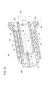
- FIG. 3 is an exploded perspective view of the pusher mechanism shown in FIG. 2. It is sectional drawing of the initial state of the pusher mechanism shown in FIG. In the pusher mechanism shown in FIG. 2, it is sectional drawing of the state which the 1st moving member advanced with respect to the 2nd moving member.
- FIG. 6 is a cross-sectional view of a state where the second moving member has further advanced slightly from the state of FIG. 5.
- FIG. 6 is a cross-sectional view of a state in which the engagement of the screw portion and the first protrusion is released and the screw portion and the second protrusion are engaged when the second moving member further advances slightly from the state of FIG. 5. . It is sectional drawing of the state which the expansion
- FIG. 10 is a perspective cross-sectional view illustrating a rotation operation of a lock operation of the pusher mechanism illustrated in FIG. 9.
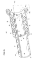
- FIG. 10 is a perspective cross-sectional view illustrating a locking operation of the locking operation of the pusher mechanism illustrated in FIG. 9. It is a perspective view of the initial state of the pusher mechanism which concerns on a 3rd structural example. It is a disassembled perspective view of the pusher mechanism shown in FIG. It is sectional drawing of the initial state of the pusher mechanism shown in FIG.
- FIG. 14 is a cross-sectional view of the pusher mechanism shown in FIG. 13 in a state in which the first moving member has advanced with respect to the second moving member.
- FIG. 17A is a cross-sectional view of the state in which the second moving member has advanced a little further from the state of FIG. 16 and FIG. 17B is a cross-sectional view along the line XVIIB-XVIIB in FIG. 17A.
- 18A is a cross-sectional view of the state in which the second moving member has advanced a little further from the state of FIG. 17A
- FIG. 18B is a cross-sectional view along the line XVIIIB-XVIIIB in FIG. 18A.
- FIG. 14 is a cross-sectional view showing a state where the extension operation of the pusher mechanism shown in FIG. 13 is completed. It is a disassembled perspective view of the pusher mechanism which concerns on a 4th structural example.
- FIG. 24 is a perspective cross-sectional view illustrating a rotation operation of a lock operation of the pusher mechanism illustrated in FIG. 23.
- FIG. 24 is a perspective cross-sectional view illustrating the locking operation of the locking operation of the pusher mechanism illustrated in FIG. 23.
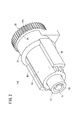
- the medicinal solution administration device 10 continuously administers the medicinal solution M filled in the cylinder 12 into the living body over a relatively long time (for example, several minutes to several hours) under the pressing action of the pusher mechanism 14A. To do.
- the chemical solution administration device 10 may intermittently administer the chemical solution M into the living body.
- the drug solution M include protein preparations, narcotic analgesics, diuretics and the like.
- a patch-type tube 17 with a needle is connected to the drug administration device 10 as an administration line 16, and the drug M discharged from the cylinder 12 has a needle. It is injected into the patient's body through the tube 17.
- the tube 17 with a needle includes a connector 18 that can be connected to the distal end portion 12c of the cylindrical body 12 provided with the discharge port 12e, a flexible liquid supply tube 19 that has one end connected to the connector 18, and a liquid supply tube.
- a patch part 20 that is connected to the other end of the tube 19 and can be attached to the skin S, and a needle 21 protruding from the patch part 20 are provided.
- the needle 21 is punctured substantially perpendicularly to the skin S.
- the needle 21 may be punctured obliquely with respect to the skin S.
- the administration line 16 connected to the drug solution administration device 10 is not limited to the above-described patch-type tube 17 with a needle, and is, for example, a puncture needle (such as a winged needle) connected to the tip of the liquid delivery tube 19. May be.
- the administration line 16 may be a bent needle that can be connected to the distal end portion 12 c of the cylindrical body 12 without using the liquid feeding tube 19.
- the bent needle is bent, for example, approximately 90 ° downward from the distal end portion 12c of the cylindrical body 12, and is perpendicular to the skin S as the drug solution administration device 10 is fixed (attached) to the skin S. Punctured.
- the distal end portion 12c of the cylindrical body 12, the administration line, and a part of the needle may be inside the cylindrical body 12, and the distal end of the needle may protrude from the cylindrical body 12. Even in this case, the needle is punctured perpendicularly to the skin S as the medicinal solution administration device 10 is fixed (attached) to the skin S.
- the drug solution administration device 10 includes a cylinder body 12 filled with the drug solution M, a gasket 22 slidably disposed in the cylinder body 12, a pusher mechanism 14A connected to the gasket 22, and a pusher mechanism 14A.
- a drive unit 23 for driving, a battery 26 for supplying electric power necessary for the operation of the drug solution administration device 10, a control unit 24 for controlling the drive unit 23, and a housing 25 for housing them are provided.
- the cylinder 12 is formed in a hollow cylindrical shape having a chemical solution chamber 13 inside.
- the cylindrical body 12 includes a barrel portion 12a having a constant inner diameter and outer diameter in the axial direction, and a shoulder portion 12b whose inner diameter and outer diameter are tapered from the distal end of the barrel portion 12a toward the distal end. And a tip portion 12c protruding from the shoulder portion 12b in the tip direction.
- a proximal end opening 12d is formed at the proximal end of the body portion 12a.
- a discharge port 12e that communicates with the chemical chamber 13 is formed at the distal end portion 12c.
- the chemical solution M is filled in the cylindrical body 12 in advance.
- the gasket 22 is made of an elastic resin material such as a rubber material or an elastomer material, and the outer peripheral portion thereof is in liquid-tight contact with the inner peripheral surface of the cylindrical body 12 (body portion 12a), so that the proximal end side of the chemical chamber 13 is formed. Closed liquid-tight.
- the gasket 22 has a base portion 22a whose outer peripheral surface is in liquid-tight contact with the body portion 12a of the cylindrical body 12, and protrudes from the base portion 22a in the distal direction and has an outer diameter that is the same as that of the shoulder portion 12b of the cylindrical body 12 in the distal direction. And a conical portion 22b having a tapered diameter. In the initial state of the drug solution administration device 10 shown in FIG. 1, the gasket 22 is positioned on the distal end side with respect to the proximal end of the cylindrical body 12.
- the pusher mechanism 14A can be extended in the axial direction under the drive action of the drive unit 23, and the gasket 22 connected to the distal end thereof is advanced in the cylindrical body 12 along with the extension. Is configured to extrude.
- the distal end side of the pusher mechanism 14 ⁇ / b> A is inserted into the proximal end side of the cylindrical body 12, and the proximal end side of the pusher mechanism 14 ⁇ / b> A is proximal to the proximal end opening 12 d of the cylindrical body 12. Protrudes in the direction. That is, the proximal end side of the pusher mechanism 14 ⁇ / b> A is exposed to the outside of the cylindrical body 12. Details of the pusher mechanism 14A will be described later.
- the drive unit 23 uses the battery 26 as a power source and a motor 27 that is driven and controlled under the control action of the control unit 24, and a power transmission that decelerates the rotation of the motor 27 and transmits it to the rotary member 30 of the pusher mechanism 14A described later. Part 28.
- the power transmission unit 28 is a gear mechanism having a plurality of gears 29.
- the plurality of gears 29 have an output gear 29a.
- the output gear 29a meshes with the rotating member 30 of the pusher mechanism 14A.
- the control unit 24 can control the motor 27 so that the pusher mechanism 14A extends at a predetermined constant speed. Thereby, the chemical
- the housing 25 is a hollow member configured to accommodate the above-described cylinder 12, gasket 22, pusher mechanism 14 ⁇ / b> A, driving unit 23, battery 26, and control unit 24.
- a distal end portion 12c of the cylindrical body 12 protrudes from the housing 25 and is exposed to the outside.
- the housing 25 has an upper surface 25a and a bottom surface 25b.
- the medicinal-solution administration device 10 can be configured as, for example, a patch type that is used by being attached to the skin S of a patient. In the case of such a patch type, a sheet-like sticking part (adhesive part) that can be stuck to the skin S is provided on the bottom surface 25 b of the housing 25. In the initial state of the chemical solution administration device 10, a peelable protective sheet is attached to the attaching surface of the attaching portion.
- the medicinal solution administration device 10 may be configured as a type in which an attachment such as a hook or a clip is provided on the back surface of the housing 25 and attached to a patient's clothes (for example, a waist portion of trousers).
- an attachment such as a hook or a clip
- the cylindrical body 12 filled with the chemical M, the gasket 22 slidably disposed in the cylindrical body 12, and the pusher mechanism 14A are combined in advance and inserted into the housing 25 at the time of use. But you can.
- a mounting portion for mounting the pusher mechanism 14 ⁇ / b> A on the cylindrical body 12 is provided on the pusher mechanism 14 ⁇ / b> A and the cylindrical body 12.
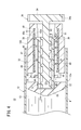
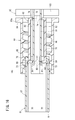
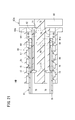
- the pusher mechanism 14 ⁇ / b> A includes a rotatable rotating member 30, a first moving member 31 that can move in the axial direction with respect to the rotating member 30, and a shaft with respect to the rotating member 30.
- a second moving member 32 that is movable in the direction, and a support member 33 that supports the second moving member 32 so as to be movable in the axial direction.
- the rotating member 30 includes a gear portion 34 having a tooth portion 34 a formed on the outer peripheral portion, a shaft portion 35 protruding from the center portion of the gear portion 34 in the distal direction, and an outer peripheral surface of the shaft portion 35. And a screw portion 36 formed in a spiral shape.
- the tooth portion 34a of the gear portion 34 meshes with the output gear 29a (see FIG. 1) of the drive portion 23 described above.
- the rotating member 30 is rotationally driven by the rotation of the output gear 29a.
- the rotating member 30 is disposed such that the rotation axis of the gear portion 34 is positioned on the central axis a (see FIG. 1) of the cylindrical body 12. The rotating member 30 is restricted so as not to move relative to the cylindrical body 12 in the axial direction.
- the shaft portion 35 extends along the rotation axis on the rotation axis of the gear portion 34.
- the screw portion 36 has a form of a male screw that protrudes radially outward from the outer peripheral surface of the shaft portion 35.
- the screw portion 36 is formed from the proximal end side of the shaft portion 35 (a position slightly on the distal end side with respect to the proximal end of the shaft portion 35) to the distal end of the shaft portion 35.
- the first moving member 31 is formed of a hollow cylindrical body having a first lumen 31a, and is disposed outside the shaft portion 35 of the rotating member 30.
- the gasket 22 (see FIG. 1) described above is disposed in front of the first moving member 31.
- the first moving member 31 can advance with respect to the rotating member 30, the second moving member 32, and the support member 33.
- the first moving member 31 includes a first cylindrical body portion 37 formed in a hollow cylindrical shape, a first projecting portion 38 that can be engaged with the screw portion 36 of the rotating member 30, and a second moving member.
- 32 has a claw portion 39 (first engagement portion) that can be engaged with an engagement groove portion 44 described later, and a pressing portion 53 that can press the gasket 22.
- the front end surface of the first moving member 31 constitutes the pressing portion 53.
- the first cylindrical body portion 37 has a distal end opening and a proximal end opening, and a first lumen 31a is formed between the distal end opening and the proximal end opening.
- the first protrusion 38 protrudes radially inward from the inner peripheral surface of the proximal end portion of the first cylindrical body portion 37.
- a plurality of (two in the illustrated example) first protrusions 38 are provided at intervals in the circumferential direction.
- the plurality of first protrusions 38 are provided at different positions in the axial direction of the first moving member 31 and spaced in the circumferential direction so as to be arranged on a spiral having the same shape as the spiral shape of the screw part 36. Yes. Only one first protrusion 38 may be provided.
- the claw portion 39 is elastically supported. Specifically, the claw portion 39 projects outward from the base end of the elastic piece 41 that can be elastically deformed in the inner and outer directions (radial direction) of the first moving member 31.
- the elastic piece 41 is provided on the proximal end side of the first cylindrical body portion 37.
- the first cylindrical body portion 37 is formed with two slits 40 that are open in the proximal direction and penetrate in the thickness direction of the first cylindrical body portion 37. An elastic piece 41 is formed therebetween.
- a plurality of elastic pieces 41 are provided at intervals in the circumferential direction.
- the elastic piece 41 is provided at a circumferential position different from the first protrusion 38 described above. Note that only one elastic piece 41 having the claw portion 39 may be provided, but a plurality of elastic pieces 41 are preferably provided at equal intervals in the circumferential direction.
- the claw portion 39 is inserted into a guide groove 47 described later of the second moving member 32. As a result, the first moving member 31 can be displaced in the axial direction with respect to the second moving member 32 while being restricted from rotating around the axis with respect to the second moving member 32.
- the second moving member 32 is formed of a hollow cylindrical body having a second lumen 32 a and is disposed outside the first moving member 31.
- the second moving member 32 can advance relative to the rotating member 30 and the support member 33.
- the second moving member 32 includes a second cylindrical body portion 42 formed in a hollow cylindrical shape, a second protrusion 43 that can be engaged with the screw portion 36 of the rotating member 30, and a claw portion of the first moving member 31. 39 (first engaging portion) and an engaging groove portion 44 (second engaging portion) that can be engaged.
- the second cylindrical body portion 42 has a distal end opening and a proximal end opening, and a second lumen 32a is formed between the distal end opening and the proximal end opening.
- a concave guide rail 45 (guide portion) extending along the axial direction is provided on the outer peripheral portion of the second cylindrical body portion 42.
- two protrusions 46 extending in parallel to each other in the circumferential direction are formed on the outer peripheral portion of the second cylindrical body portion 42, and a guide rail is provided between the two protrusions 46. 45 is formed.
- two guide rails 45 are provided at intervals in the circumferential direction.
- a plurality of guide rails 45 are preferably provided at equal intervals in the circumferential direction.
- a hole 42 a is provided at the base end of the second cylindrical body 42.
- the hole 42 a and a protrusion 51 described later of the support member 33 constitute a temporary fixing mechanism that releasably restricts (temporarily fixes) the second moving member 32 so as not to advance relative to the support member 33.
- the hole 42 a is provided at the bottom of the concave guide rail 45 and penetrates the peripheral wall of the second cylindrical body 42 in the thickness direction.
- a recess that opens to the bottom of the guide rail 45 may be provided.
- the second protrusion 43 protrudes radially inward from the inner peripheral surface of the base end of the second cylindrical body 42.
- a plurality (two in the illustrated example) of the second protrusions 43 are provided.
- the plurality of second projecting portions 43 are provided at different positions in the axial direction of the second moving member 32 so as to be spaced apart in the circumferential direction so as to be arranged on a spiral having the same shape as the spiral shape of the screw portion 36. Yes. Only one second protrusion 43 may be provided.
- the engaging groove 44 is provided in the vicinity of the tip of the second cylindrical body 42.
- a guide groove 47 extending in the axial direction is provided on the inner peripheral surface of the second cylindrical body portion 42, and the engagement groove portion 44 is provided at the distal end portion of the guide groove 47.
- the engagement groove portion 44 in the illustrated example is a through hole that penetrates the peripheral wall portion of the second cylindrical body portion 42 in the thickness direction.
- the engagement groove portion 44 may be a bottomed hole (concave portion) that opens to the second lumen 32a and has a depth toward the radially outer side of the second cylindrical body portion 42.
- a plurality (two in the illustrated example) of engaging groove portions 44 are provided at intervals in the circumferential direction.
- a plurality of engagement grooves 44 are preferably provided at equal intervals in the circumferential direction so as to correspond to the claw 39 of the first moving member 31.
- a plurality (two in the illustrated example) of the guide grooves 47 are provided at intervals in the circumferential direction. Note that only one guide groove 47 may be provided, but a plurality of guide grooves 47 are preferably provided at equal intervals in the circumferential direction so as to correspond to the claw portions 39 of the first moving member 31.
- the support member 33 includes a base portion 48 fixed to the inner surface of the housing 25 and a plurality of (two in the illustrated example) support arms 49 extending from the base portion 48 in the distal direction.
- the base 48 has a through hole 48a.
- the shaft portion 35 of the rotating member 30 is inserted through the through hole 48a.
- the plurality of support arms 49 extend in parallel to each other.
- a guide protrusion 50 protruding inward is provided inside each support arm 49.
- the guide protrusion 50 extends parallel to the axial direction of the second moving member 32.
- the guide protrusion 50 is inserted into the guide rail 45 of the second moving member 32.
- the second moving member 32 can be displaced in the axial direction with respect to the rotating member 30 and the support member 33 while the rotation around the axis is restricted.
- a plurality of support arms 49 are preferably provided at equal intervals in the circumferential direction so as to correspond to the guide rail 45 of the second moving member 32.
- the support arms 49 having the guide rails 45 and the guide projections 50 are respectively provided in the circumferential direction at equal intervals (two in the illustrated example), the inclination of the second moving member 32 with respect to the support member 33. Is suppressed.
- the base end of the guide protrusion 50 is provided with a protrusion 51 that protrudes inward.
- the protrusion 51 is inserted into the hole 42a (the protrusion 51 and the hole 42a are engaged).
- the second moving member 32 is temporarily fixed to the support member 33.
- a predetermined force or more in the distal direction is applied to the second moving member 32, the engagement between the protrusion 51 and the hole 42a is released, and the second moving member 32 moves forward by the force in the distal direction.
- the drug solution administration device 10 shown in FIG. 1 when the drug solution administration device 10 shown in FIG. 1 is used, the drug solution administration device 10 is connected to an administration line 16 (for example, the above-described tube 17 with a needle). And the chemical
- an administration line 16 for example, the above-described tube 17 with a needle.
- medical solution administration apparatus 10 is attached to a patient by affixing on the skin S or mounting
- the needle 21 is punctured into the skin S.
- the drug solution administration device 10 may be attached to the patient before the needle 21 punctures the skin S.
- the pusher mechanism 14A When the medicinal solution administration device 10 receives a predetermined operation start command, the pusher mechanism 14A is extended in a plurality of stages under the drive action of the drive unit 23, and the gasket 22 is pressed against the pusher mechanism 14A along with this extension operation. Then, the chemical liquid M in the cylindrical body 12 is pushed out by moving forward. The medicinal solution M pushed out from the cylindrical body 12 is administered (injected) into the patient's body through the administration line 16 punctured by the patient.
- the extension operation of the pusher mechanism 14A includes a first extension operation and a second extension operation after the first extension operation, as will be described below.
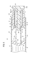
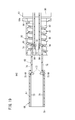
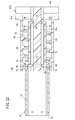
- the pusher mechanism 14 ⁇ / b> A As shown in FIG. 4, in the initial state of the pusher mechanism 14 ⁇ / b> A (the pusher mechanism 14 ⁇ / b> A has not started operation and the discharge of the chemical M from the cylindrical body 12 has not started), the pusher mechanism Each part of 14A is as follows.
- the rotating member 30, the first moving member 31, and the second moving member 32 are arranged at positions that overlap each other in the axial direction.
- the screw portion 36 of the rotating member 30 and the first protrusion 38 of the first moving member 31 are engaged.
- the screw portion 36 of the rotating member 30 and the second protrusion 43 of the second moving member 32 are not engaged.
- the claw portion 39 (first engagement portion) and the engagement groove portion 44 (second engagement portion) are not engaged.
- the hole 42a of the second moving member 32 and the protrusion 51 of the support member 33 are engaged.
- the pressing portion 53 that is the distal end surface of the first moving member 31 is inserted into a groove 22 c provided on the proximal end surface of the gasket 22.
- the pressing portion 53 is separated from the bottom of the groove 22c.
- the inner diameter of the groove 22 c is slightly larger than the outer diameter of the distal end portion of the first moving member 31. In the initial state, the pressing portion 53 may be in contact with the bottom of the groove 22c.
- the groove 22 c may not be provided on the base end surface of the gasket 22.
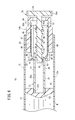
- the first movement is performed under the engaging action of the screw portion 36 and the first projection portion 38 as shown in FIG.
- the member 31 moves forward to a predetermined position with respect to the rotating member 30 and the second moving member 32.
- the relative rotation about the axis of the first moving member 31 with respect to the second moving member 32 is restricted, and the relative rotation about the axis of the second moving member 32 with respect to the support member 33 is restricted.
- the first moving member 31 does not rotate with the rotation. That is, the first protrusion 38 does not rotate. Accordingly, the first protrusion 38 is fed in the distal direction by the rotating screw portion 36. Thereby, the 1st movement member 31 advances.
- the pressing portion 53 of the first moving member 31 contacts the bottom of the groove 22 c of the gasket 22.
- the gasket 22 is pressed in the distal direction by the pressing portion 53 as the first moving member 31 moves forward, and the gasket 22 moves forward together with the first moving member 31 in the cylindrical body 12.
- the chemical M is discharged through the discharge port 12e (see FIG. 1) of the cylindrical body 12.
- the tip of the first moving member 31 is inserted into the groove 22 c of the gasket 22, so that the first moving member 31 is prevented from tilting in the cylindrical body 12. This prevents the pressing portion 53 of the first moving member 31 from pressing the gasket 22 in a direction inclined with respect to the axis of the cylindrical body 12.
- the second moving member 32 receives a force in the distal direction from the first moving member 31 due to the frictional resistance between the first moving member 31 and the second moving member 32.
- the hole 42 a of the second moving member 32 and the protrusion 51 of the support member 33 are engaged.
- the engagement force between the hole 42a and the protrusion 51 is greater than the force in the distal direction that the second moving member 32 receives from the first moving member 31 due to frictional resistance. For this reason, the 2nd moving member 32 does not advance at the time of 1st expansion
- the engagement between the screw portion 36 and the first protrusion 38 is maintained. Therefore, when the rotating member 30 further rotates from the state of FIG. 5, the first moving member 31 further advances under the engaging action of the screw portion 36 and the first projecting portion 38 as shown in FIG. 6. At this time, since the claw portion 39 and the engaging groove portion 44 are engaged, the second moving member 32 moves forward together with the first moving member 31 by being pulled in the distal direction by the first moving member 31.
- the force by which the first moving member 31 pulls the second moving member 32 in the distal direction in a state where the claw portion 39 and the engaging groove portion 44 are engaged is the hole 42 a of the second moving member 32 and the protruding portion of the support member 33. It is larger than the engaging force with 51.
- the gasket 22 advances in the cylindrical body 12 by being pressed by the pressing portion 53 of the first moving member 31.
- the gasket 22 advances in the cylindrical body 12 by being pressed by the pressing portion 53 of the first moving member 31. Then, when the gasket 22 reaches the most advanced position of the movable range (when the gasket 22 contacts the shoulder 12b of the cylindrical body 12), the advancement of the first moving member 31 and the second moving member 32 stops. . That is, the extension of the pusher mechanism 14A is completed.
- the pusher mechanism 14A can be shortened because the pusher mechanism 14A extends over a plurality of stages. Can be achieved.
- By downsizing the apparatus it is possible to reduce the area required for sticking when sticking to the patient's body surface, and thus it can be easily applied to uses such as sticking to the patient's body surface. Further, by reducing the size of the apparatus, it is possible to improve usability such as carrying and storage.
- the drug solution administration device 10 of the present invention it is mechanically movable by the engagement structure (engagement between the screw portion 36 and the first projection portion 38 and engagement between the screw portion 36 and the second projection portion 43). Since the parts (the first moving member 31 and the second moving member 32) are moved, the medicinal solution M can be administered at a constant speed.
- the first moving member 31 moves forward to a predetermined position with respect to the second moving member 32, the claw portion 39 and the engaging groove portion 44 are engaged, whereby the first moving member 31 is engaged.
- the relative displacement in the axial direction with respect to the second moving member 32 is restricted.
- the engagement between the screw portion 36 and the first protrusion 38 after the screw portion 36 and the second protrusion 43 are engaged with the rotation of the rotating member 30.
- the match is released.
- the transition from the first extension operation to the second extension operation can be smoothly performed by changing the engagement partner of the screw part 36 from the first protrusion 38 to the second protrusion 43 with good timing. .
- the drug solution administration device 10 is provided with an elastically supported claw portion 39 and an engagement groove portion 44 with which the claw portion 39 can be engaged. For this reason, when the 1st moving member 31 advances to the maximum with respect to the 2nd moving member 32, the nail
- the screw portion 36 has a male screw shape
- the first moving member 31 is formed of a hollow cylindrical body having a first lumen 31 a
- the first projecting portion 38 is a first moving member. It protrudes toward the inside of 31, and a male screw is inserted through the first lumen 31a in the initial state.
- the second moving member 32 is formed of a hollow cylindrical body having a second lumen 32a, and the second projecting portion 43 protrudes toward the inside of the second moving member 32, so that the second lumen 32a is male.
- the screw and the first moving member 31 are inserted. With this configuration, it is easy to reduce the outer diameter of the pusher mechanism 14A.
- the medicinal solution administration device 10 includes a support member 33 that guides the second moving member 32 in the axial direction while restricting the rotation of the second moving member 32, and the second moving member 32 rotates the first moving member 31.
- a guide groove 47 (guide portion) that guides the first moving member 31 in the axial direction while regulating is provided.
- the support member 33, the second moving member 32 (protrusion 51 and hole 42 a), and the second moving member 32 are held so as to hold the position of the second moving member 32 with respect to the rotating member 30 until the first extension operation is completed. Are engaged.
- the rotating member 30 rotates with the screw portion 36 and the first protrusion 38 engaged, the engagement between the support member 33 and the second moving member 32 is released. With this configuration, it is possible to prevent the second moving member 32 from moving forward by being pulled forward by the first moving member 31 during the first extension operation.
- the pusher mechanism 14A instead of the above-described pusher mechanism 14A (hereinafter, also referred to as “the pusher mechanism 14A according to the first configuration example”), for example, the pushers according to the second to fifth configuration examples described below. Child mechanisms 14B to 14E may be provided.
- the pusher mechanism 14B according to the second configuration example shown in FIG. 9 is different from the pusher mechanism 14A described above in the configuration of the first moving member 31b and the second moving member 32b.
- the first moving member 31 b has a convex portion 54 (first engaging portion) that protrudes outward from the outer surface of the proximal end portion of the first cylindrical body portion 37.
- the convex portion 54 can be engaged with a lock groove 55 (see FIG. 10B) described later.
- a plurality (two in the illustrated example) of the convex portions 54 are provided at intervals in the circumferential direction. Although only one convex portion 54 may be provided, a plurality of convex portions 54 are preferably provided at equal intervals in the circumferential direction.
- a first protrusion 38 is provided on the inner peripheral portion of the first moving member 31b.
- a guide groove 47 similar to the guide groove 47 of the second moving member 32 and a lock groove 55 (second engagement) shorter than the guide groove 47 are formed in the inner peripheral portion of the second moving member 32b.
- a relay groove 56 that connects one end (tip) of the guide groove 47 and one end (tip) of the lock groove 55 is provided.
- the lock groove 55 communicates with the guide groove 47 via the relay groove 56 and extends from the relay groove 56 in the proximal direction.
- the lock groove 55 extends in parallel with the guide groove 47, and slightly extends in the proximal direction from the end of the relay groove 56 on the side opposite to the guide groove 47. Therefore, the base end of the lock groove 55 is on the front end side with respect to the base end of the guide groove 47.
- the extension length of the lock groove 55 from the relay groove 56 may be approximately the same as the length of the convex portion 54 along the axial direction of the first moving member 31 b or may be shorter than the length of the convex portion 54.
- the relay groove 56 extends in the circumferential direction of the second moving member 32b.
- the second moving member 32b two groove structures including the guide groove 47, the relay groove 56, and the lock groove 55 are provided symmetrically with respect to the central axis of the second moving member 32b.
- the convex part 54 of the 1st moving member 31b and the groove structure of the 2nd moving member 32b are each provided with two or more at equal intervals in the circumferential direction. Thereby, the inclination of the 1st moving member 31b with respect to the 2nd moving member 32b is suppressed.
- the other part of the pusher mechanism 14B is configured similarly to the pusher mechanism 14A described above.
- the convex portion 54 is inserted into the guide groove 47 in the initial state of the pusher mechanism 14B.
- the pusher mechanism 14B extends by the first moving member 31b moving forward under the engaging action of the screw portion 36 and the first protrusion 38 (first extension). Operation).
- the convex portion 54 advances in the guide groove 47.
- the convex portion 54 reaches the most distal portion of the guide groove 47.
- the protrusion 54 enters the lock groove 55 via the relay groove 56, so that the relative movement of the first moving member 31b in the proximal direction with respect to the second moving member 32b is restricted (locked).
- the locking operation that restricts the relative movement of the first moving member 31b in the proximal direction with respect to the second moving member 32b in the pusher mechanism 14B is a rotation operation (FIG. 11) that is a first locking operation; And a locking operation (FIG. 12) which is a second locking operation after the rotation operation.
- the first moving member 31b is rotated in the direction of arrow A as described above by the rotational force received from the rotating member 30 rotating the first moving member 31b.
- the convex portion 54 reaches the end of the relay groove 56 on the lock groove 55 side.
- the second moving member 32 b moves forward with respect to the first moving member 31 b, so that the convex portion 54 enters the lock groove 55, and the convex groove 54 is moved by the lock groove 55.
- Lock In this locking operation, the screw portion 36 of the rotating member 30 and the second projecting portion 43 of the second moving member 32b are engaged, and the screw portion 36 and the first projecting portion 38 of the first moving member 31b are engaged. This is done after is released.
- the rotating member 30 rotates in a state where the engagement between the screw portion 36 and the first protrusion 38 of the first moving member 31b is released and the convex portion 54 is positioned at the end of the relay groove 56 on the lock groove 55 side.
- the second moving member 32b advances under the engaging action of the screw portion 36 and the second protrusion 43.
- the cylindrical body 12, the gasket 22, and the chemical liquid M are not illustrated, but the first moving member 31 b is advanced as in the case where the pusher mechanism 14 ⁇ / b> A operates. Along with this, the gasket 22 is pressed by the pressing portion 53 and advances in the cylindrical body 12, whereby the chemical liquid M is discharged from the cylindrical body 12.
- the convex portion 54 is provided on the outer surface of the first moving member 31b (the outer surface of the first cylindrical body portion 37). For this reason, it is possible to have higher strength than the claw portion 39 provided on the first moving member 31 of the pusher mechanism 14A described above. Therefore, the mechanism portion that locks the first moving member 31b with respect to the second moving member 32b can be structurally stabilized.
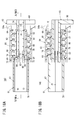
- the pusher mechanism 14C according to the third configuration example shown in FIGS. 13 and 14 includes a rotatable rotating member 60, a first moving member 61 that can move in the axial direction with respect to the rotating member 60, and the rotating member 60.
- a second moving member 62 that is movable in the axial direction and a support member 63 that supports the second moving member 62 so as to be movable in the axial direction are provided.
- the rotating member 60 includes a gear portion 64 having a tooth portion 64 a formed on the outer peripheral portion, a hollow cylindrical tube portion 65 protruding from the gear portion 64 in the distal direction, and an inner portion of the tube portion 65. And a screw portion 66 formed in a spiral shape on the peripheral surface.
- the tooth portion 64a of the gear portion 64 meshes with the output gear 29a (see FIG. 1) of the power transmission portion 28 described above.
- the rotation member 60 is rotationally driven by the rotation of the output gear 29a.
- the rotating member 60 is disposed such that the rotation axis of the gear portion 64 is positioned on the central axis a (see FIG. 1) of the cylindrical body 12. Further, the rotating member 60 is restricted so as not to move relative to the cylindrical body 12 in the axial direction.
- the cylindrical portion 65 extends along the rotational axis on the rotational axis of the gear portion 64. In the initial state of the pusher mechanism 14C, at least the distal end side of the cylindrical portion 65 is inserted into the cylindrical body 12 (see FIG. 1).
- the screw portion 66 has a form of a female screw that protrudes radially inward from the inner peripheral surface of the cylindrical portion 65. The screw portion 66 is formed from the distal end side to the proximal end side of the cylindrical portion 65.
- the first moving member 61 is formed of a hollow cylindrical body having a first lumen 61 a and is disposed inside the rotating member 60.
- a gasket 22 (see FIG. 1) is connected to the tip of the first moving member 61.
- the first moving member 61 can advance with respect to the rotating member 60, the second moving member 62, and the support member 63.
- the first moving member 61 includes a first cylindrical body 67 formed in a hollow cylindrical shape, a first protrusion 68 that can be engaged with the screw portion 66 of the rotating member 60, and a second moving member.
- 62 includes an engaging groove 69 (first engaging portion) that can be engaged with a claw 73 described later, and a pressing portion 79 that can press the gasket 22 (see FIG. 1).
- the front end surface of the first moving member 61 forms a pressing portion 79.
- the first cylindrical body 67 has a distal end opening and a proximal end opening, and a first lumen 61a is formed between the distal end opening and the proximal end opening.
- the first protrusion 68 protrudes radially outward from the outer peripheral surface of the base end of the first cylindrical body 67.
- a plurality (two in the illustrated example) of first protrusions 68 are provided at intervals in the circumferential direction.
- the plurality of first projecting portions 68 are provided at different positions in the axial direction of the first moving member 61 so as to be spaced apart in the circumferential direction so as to be arranged on a spiral having the same shape as the spiral shape of the screw portion 66. Yes. Note that only one first protrusion 68 may be provided.
- the engaging groove 69 is provided in the vicinity of the proximal end of the first cylindrical body 67.
- a guide groove 70 extending in the axial direction is provided on the inner peripheral surface of the first cylindrical body portion 67, and the engagement groove portion 69 is provided at the base end portion of the guide groove 70.
- the engagement groove 69 in the illustrated example is a through hole that penetrates the peripheral wall of the first cylindrical body 67 in the thickness direction.
- the engagement groove portion 69 may be a bottomed hole (concave portion) that opens to the first lumen 61 a and has a depth toward the radially outer side of the first cylindrical body portion 67.
- a plurality (two in the illustrated example) of engaging groove portions 69 are provided at intervals in the circumferential direction. Note that only one engagement groove 69 may be provided, but a plurality of engagement grooves 69 are preferably provided at equal intervals in the circumferential direction.
- a plurality of guide grooves 70 (two in the illustrated example) are provided at intervals in the circumferential direction. Although only one guide groove 70 may be provided, a plurality of guide grooves 70 are preferably provided at equal intervals in the circumferential direction.
- the second moving member 62 is formed of a hollow cylindrical body having a second lumen 62a, and is arranged inside the first moving member 61.
- the second moving member 62 can advance with respect to the rotating member 60 and the support member 63.
- the second moving member 62 includes a second cylindrical body 71 formed in a hollow cylindrical shape, a second protrusion 72 that can be engaged with the threaded portion 66 of the rotating member 60, and the engagement of the first moving member 61.
- a claw portion 73 (second engagement portion) that can engage with the groove portion 69 is provided.
- the second cylindrical body 71 has a distal end opening and a proximal end opening, and a second lumen 62a is formed between the distal end opening and the proximal end opening.
- the second protrusion 72 protrudes radially outward from the outer peripheral surface of the base end of the second cylindrical body 71.
- a plurality (two in the illustrated example) of the second protrusions 72 are provided at intervals in the circumferential direction.
- the plurality of second projecting portions 72 are provided at different positions in the axial direction of the second moving member 62 so as to be spaced apart in the circumferential direction so as to be arranged on a spiral having the same shape as the spiral shape of the screw portion 66. Yes. Only one second protrusion 72 may be provided.
- a guide projection 74 inserted into a guide rail 82 described later of the support member 63 is provided on the inner periphery of the base end portion of the second cylindrical body 71.
- a plurality of guide protrusions 74 are provided at intervals in the circumferential direction. Although only one guide protrusion 74 may be provided, a plurality of guide protrusions 74 are preferably provided at equal intervals in the circumferential direction.
- the claw portion 73 is elastically supported. Specifically, the claw portion 73 protrudes outward from the tip of the elastic piece 76 that can be elastically deformed in the inner and outer directions (radial direction) of the second moving member 62. The claw 73 can be engaged with the engagement groove 69 of the first moving member 61.
- the elastic piece 76 is provided on the distal end side of the second cylindrical body 71.
- the second cylindrical body 71 is formed with two parallel slits 75 that open in the distal direction and penetrate in the thickness direction of the second cylindrical body 71.
- An elastic piece 76 is formed on the surface.
- a plurality (two in the illustrated example) of elastic pieces 76 are provided at intervals in the circumferential direction. Note that only one elastic piece 76 may be provided.
- the claw portion 73 is inserted into the guide groove 70 of the first moving member 61.
- the first moving member 61 can be displaced in the axial direction with respect to the second moving member 62 while being restricted from rotating around the axis with respect to the second moving member 62.
- a plurality of elastic pieces 76 having the claw portions 73 are preferably provided at equal intervals in the circumferential direction so as to correspond to the engagement groove portions 69 and the guide grooves 70 of the first moving member 61. Thereby, the inclination of the first moving member 61 with respect to the second moving member 62 is suppressed.
- a protrusion 77 protruding inward is provided at the tip of the claw 73.
- the protrusion 77 is closer to the small protrusion 84 on the proximal end side than the small protrusion 84 described later of the support member 63, or is engaged with the small protrusion 84.
- the 2nd moving member 62 is controlled so that advance with respect to support member 63 is releasable (temporarily fixed).
- the protruding portion 77 gets over the small protrusion 84, and the second moving member 62 moves forward by the force in the distal direction.
- the support member 63 has a base portion 80 fixed to the inner surface of the housing 25 (see FIG. 1) and a support shaft portion 81 extending from the base portion 80 in the distal direction.
- the support shaft portion 81 is formed in a hollow cylindrical shape.
- the support shaft portion 81 is inserted into the second lumen 62 a of the second moving member 62.
- a concave guide rail 82 is provided on the outer side of the support shaft 81 along the axial direction of the support shaft 81.
- the guide protrusion 74 of the second moving member 62 is inserted into the guide rail 82. Accordingly, the second moving member 62 can be displaced in the axial direction with respect to the rotating member 60 and the support member 63 while the rotation around the axis is restricted.
- a plurality of guide rails 82 are provided (see FIG. 15). Although only one guide rail 82 may be provided, a plurality of guide rails 82 are preferably provided at equal intervals in the circumferential direction so as to correspond to the guide protrusions 74 of the second moving member 62. Thereby, the inclination of the second moving member 62 with respect to the support member 63 is suppressed.
- each guide rail 82 is a slit 82a that opens in the tip direction and penetrates the peripheral wall of the support shaft 81 in the thickness direction.
- the slit 82a is provided with an elastic piece 83 extending in the distal direction from the proximal end of the slit 82a.
- the elastic piece 83 can be elastically deformed in the radial direction of the support shaft portion 81.
- a small protrusion 84 bulging outward is provided at the tip (free end) of the elastic piece 83.
- the small protrusion 84 constitutes a temporary fixing mechanism that temporarily fixes the second moving member 62 to the support member 63 together with the above-described protrusion 77 of the second moving member 62.
- each part of the pusher mechanism 14C is as follows.
- the rotating member 60, the first moving member 61, and the second moving member 62 are arranged at positions that overlap each other in the axial direction.
- the screw portion 66 of the rotating member 60 and the first protrusion 68 of the first moving member 61 are engaged.
- the screw portion 66 of the rotating member 60 and the second protrusion 72 of the second moving member 62 are not engaged.
- the claw portion 73 (first engagement portion) and the engagement groove portion 69 (second engagement portion) are not engaged.
- the protrusion 77 of the second moving member 62 and the small protrusion 84 of the support member 63 are close to or engaged with each other.
- the pusher mechanism 14C When the drive unit 23 shown in FIG. 1 starts operation, the pusher mechanism 14C is extended in a plurality of stages under the drive action of the drive unit 23. Specifically, the extension operation of the pusher mechanism 14C includes a first extension operation and a second extension operation after the first extension operation, as will be described below.
- the first moving member 61 In the first extending operation, as the rotating member 60 rotates from the initial state, the first moving member 61 is rotated by the rotating member 60 under the engaging action of the screw portion 66 and the first projecting portion 68 as shown in FIG. And it moves forward to a predetermined position with respect to the second moving member 62. In this case, the first moving member 61 is restricted from relative rotation around the axis with respect to the second moving member 62, and the second moving member 62 is restricted from relative rotation around the axis relative to the support member 63. The first moving member 61 does not rotate with the rotation. That is, the first protrusion 68 does not rotate. Accordingly, the first projecting portion 68 is sent in the distal direction by the rotating screw portion 66.
- the first moving member 61 moves forward.
- the first moving member 61 pulls the second moving member 62 in the distal direction with a weak force.
- the pulling force is smaller than the force necessary for the protruding portion 77 of the second moving member 62 to get over the small protrusion 84 of the support member 63. Thereby, it is possible to prevent the second moving member 62 from moving forward by being pulled forward by the first moving member 61 during the first extending operation.
- the engagement between the screw portion 66 and the first protrusion 68 is maintained. Therefore, when the rotating member 60 further rotates from the state shown in FIG. 16, the first moving member 61 further advances under the engaging action of the screw portion 66 and the first projecting portion 68 as shown in FIGS. 17A and 17B. At this time, since the claw 73 and the engaging groove 69 are engaged, the second moving member 62 moves forward together with the first moving member 61 by being pulled in the distal direction by the first moving member 61.
- the force by which the first moving member 61 pulls the second moving member 62 in the distal direction in a state where the claw 73 and the engaging groove 69 are engaged is the small protrusion of the protruding portion 77 of the second moving member 62 and the supporting member 63. It is larger than the engaging force with 84. Therefore, when the second moving member 62 further advances from the state of FIG. 17A, the protrusion 77 gets over the small protrusion 84, and the engagement between the protrusion 77 and the small protrusion 84 is released. As shown in FIG. 17B, at this time, the screw portion 66 and the second protrusion 72 are not yet engaged.
- the cylindrical body 12 the gasket 22, and the chemical liquid M are not shown.
- the pusher mechanism 14A operates, the gasket moves with the advance of the first moving member 61.
- the chemical liquid M is discharged from the cylindrical body 12 by 22 being pressed by the pressing portion 79 and moving forward in the cylindrical body 12.
- the pusher mechanism 14C extends over a plurality of stages, similarly to the pusher mechanism 14A described above, the pusher mechanism 14C can be shortened, and accordingly, the drug solution administration device 10 (see FIG. 1). Can be miniaturized.
- the support member 63a has a locking protrusion 86 (see also FIG. 21) protruding outward from the bottom of the guide rail 82.
- the locking protrusion 86 is provided on the proximal end side of the guide rail 82.
- a plurality of (two in the illustrated example) locking projections 86 are provided at intervals in the circumferential direction. Only one locking protrusion 86 may be provided.
- the support shaft portion 81a protruding from the base portion 80 in the distal direction has a solid structure, and a slit 82a and an elastic piece are formed at the distal end portion of the support shaft portion 81a. 83 is not provided.
- the guide protrusion 74 is closer to the locking protrusion 86 on the proximal end side than the locking protrusion 86 or is engaged with the locking protrusion 86.
- the second moving member 62 is regulated (temporarily fixed) so as to be released so as not to move forward with respect to the support member 63a.
- the guide protrusion 74 gets over the locking protrusion 86, and the second moving member 62 moves forward by the force in the distal direction.
- the guide protrusion 74 and the locking protrusion 86 constitute a temporary fixing mechanism that releasably restricts the second moving member 62 so as not to advance with respect to the support member 63a.
- the first moving member 61 advances under the engaging action of the screw portion 66 and the first projecting portion 68, whereby the pusher mechanism 14D expands (first 1 extension operation).
- the first moving member 61 pulls the second moving member 62 in the distal direction with a weak force.
- This pulling force causes the guide protrusion 74 of the second moving member 62 to get over the locking protrusion 86 of the support member 63a. Less than necessary force. Thereby, it is possible to prevent the second moving member 62 from moving forward by being pulled forward by the first moving member 61 during the first extending operation.
- the claw portion 73 and the engaging groove portion 69 are engaged. Thereby, the axial relative displacement of the first moving member 61 with respect to the second moving member 62 is restricted.
- the rotating member 60 further rotates from this state, the first moving member 61 further advances.
- the claw portion 73 and the engagement groove portion 69 are engaged, the second moving member 62 is pulled in the distal direction by the first moving member 61, thereby causing the first moving member 61. Move forward with.
- the force by which the first moving member 61 pulls the second moving member 62 in the distal direction in a state where the claw 73 and the engaging groove 69 are engaged is the engagement between the guide protrusion 74 of the second moving member 62 and the support member 63a. It is larger than the engaging force with the protrusion 86. Therefore, as shown in FIG. 22, when the guide protrusion 74 gets over the locking protrusion 86, the engagement between the guide protrusion 74 and the locking protrusion 86 is released.
- the subsequent operation of the pusher mechanism 14D is the same as the operation of the pusher mechanism 14C according to the third configuration example described above.
- 20 to 22 the cylindrical body 12, the gasket 22, and the chemical liquid M are not shown.
- the gasket 22 is moved along with the advancement of the first moving member 61.
- the chemical liquid M is discharged from the cylindrical body 12 by being pressed by the pressing portion 79 and moving forward in the cylindrical body 12.
- the pusher mechanism 14E according to the fifth configuration example shown in FIG. 23 is different from the pusher mechanism 14C according to the third configuration example in the configuration of the first moving member 61b, the second moving member 62b, and the support member 63a.
- a guide groove 88 extending in the axial direction, a lock groove 89 (first engaging portion) shorter than the guide groove 88, and one end (base end) of the guide groove 88 are formed in the inner peripheral portion of the first moving member 61b. ) And one end (base end) of the lock groove 89 is provided.
- the lock groove 89 communicates with the guide groove 88 via the relay groove 90 and extends from the relay groove 90 in the front end direction, and slightly extends from the end of the relay groove 90 opposite to the guide groove 88 in the front end direction. It is extended. Therefore, the distal end of the lock groove 89 is closer to the proximal end than the distal end of the guide groove 88.
- the lock groove 89 extends in parallel with the guide groove 88.
- the extension length of the lock groove 89 from the relay groove 90 may be approximately the same as the length of the convex portion 92 along the axial direction of the second moving member 62 b or may be shorter than the length of the convex portion 92.
- the relay groove 90 extends in the circumferential direction of the first moving member 61b.
- two groove structures including the guide groove 88, the relay groove 90, and the lock groove 89 are provided symmetrically with respect to the central axis of the second moving member 62b. Only one groove structure may be provided, but a plurality of groove structures are preferably provided at equal intervals in the circumferential direction.
- the second moving member 62b has a convex portion 92 (second engaging portion) protruding outward from the outer surface of the base end portion of the second cylindrical body 71.
- the convex portion 92 can be engaged with the lock groove 89 of the first moving member 61b.
- a plurality (two in the illustrated example) of the convex portions 92 are provided at intervals in the circumferential direction.
- the convex part 92 is provided with two or more at equal intervals in the circumferential direction. Thereby, the inclination of the 1st movement member 61b with respect to the 2nd movement member 62b is suppressed.
- a guide protrusion 74 is provided on the inner peripheral portion of the proximal end of the second moving member 62b.
- the support member 63a is configured similarly to the support member 63a of the pusher mechanism 14D according to the fourth configuration example.
- the other part of the pusher mechanism 14E is configured in the same manner as the pusher mechanism 14C according to the above-described third configuration example.
- the protrusion 92 is inserted into the guide groove 88 in the initial state of the pusher mechanism 14E.
- the first moving member 61b moves forward under the engaging action of the screw portion 66 and the first protrusion 68, whereby the pusher mechanism 14E extends. (First extension operation).
- the convex portion 92 retreats relative to the guide groove 88.
- the convex portion 92 reaches the most proximal end portion of the guide groove 88 (the connection portion between the guide groove 88 and the relay groove 90). Then, when the convex portion 92 enters the lock groove 89 via the relay groove 90, the relative movement of the first moving member 61b in the proximal direction with respect to the second moving member 62b is restricted (locked).
- the locking operation that restricts the relative movement of the first moving member 61b in the proximal direction with respect to the second moving member 62b in the pusher mechanism 14E includes a rotation operation (FIG. 24) that is a first locking operation; And a locking operation (FIG. 25) which is a second locking operation after the rotation operation.
- the first moving member 61b moves forward together with the second moving member 62b as the rotating member 60 rotates.
- the pusher mechanism 14E further extends (second extending operation).
- the cylindrical body 12, the gasket 22, and the chemical liquid M are not shown. However, as in the case where the pusher mechanism 14A is operated, the gasket is moved with the advance of the first moving member 61b. The chemical liquid M is discharged from the cylindrical body 12 by 22 being pressed by the pressing portion 79 and moving forward in the cylindrical body 12.
- the convex portion 92 is provided on the outer surface of the second moving member 62b (the outer surface of the second cylindrical body portion 71). For this reason, it is possible to have higher strength than the claw portion 73 provided on the second moving member 62 of the pusher mechanism 14C described above. Therefore, the mechanism that locks the first moving member 61b with respect to the second moving member 62b can be structurally stabilized.
Landscapes
- Health & Medical Sciences (AREA)
- Vascular Medicine (AREA)
- Engineering & Computer Science (AREA)
- Anesthesiology (AREA)
- Biomedical Technology (AREA)
- Heart & Thoracic Surgery (AREA)
- Hematology (AREA)
- Life Sciences & Earth Sciences (AREA)
- Animal Behavior & Ethology (AREA)
- General Health & Medical Sciences (AREA)
- Public Health (AREA)
- Veterinary Medicine (AREA)
- Infusion, Injection, And Reservoir Apparatuses (AREA)
Abstract
Priority Applications (4)
| Application Number | Priority Date | Filing Date | Title |
|---|---|---|---|
| CN201780021897.8A CN108883228B (zh) | 2016-03-30 | 2017-03-29 | 药液施予装置 |
| JP2018508118A JP6724133B2 (ja) | 2016-03-30 | 2017-03-29 | 薬液投与装置 |
| EP17775166.6A EP3437676B1 (fr) | 2016-03-30 | 2017-03-29 | Dispositif d'administration de médicament liquide |
| US16/147,016 US10842942B2 (en) | 2016-03-30 | 2018-09-28 | Liquid medicine administration device |
Applications Claiming Priority (2)
| Application Number | Priority Date | Filing Date | Title |
|---|---|---|---|
| JP2016-067928 | 2016-03-30 | ||
| JP2016067928 | 2016-03-30 |
Related Child Applications (1)
| Application Number | Title | Priority Date | Filing Date |
|---|---|---|---|
| US16/147,016 Continuation US10842942B2 (en) | 2016-03-30 | 2018-09-28 | Liquid medicine administration device |
Publications (1)
| Publication Number | Publication Date |
|---|---|
| WO2017170629A1 true WO2017170629A1 (fr) | 2017-10-05 |
Family
ID=59965933
Family Applications (1)
| Application Number | Title | Priority Date | Filing Date |
|---|---|---|---|
| PCT/JP2017/012786 WO2017170629A1 (fr) | 2016-03-30 | 2017-03-29 | Dispositif d'administration de médicament liquide |
Country Status (5)
| Country | Link |
|---|---|
| US (1) | US10842942B2 (fr) |
| EP (1) | EP3437676B1 (fr) |
| JP (1) | JP6724133B2 (fr) |
| CN (1) | CN108883228B (fr) |
| WO (1) | WO2017170629A1 (fr) |
Cited By (4)
| Publication number | Priority date | Publication date | Assignee | Title |
|---|---|---|---|---|
| WO2019189437A1 (fr) * | 2018-03-30 | 2019-10-03 | テルモ株式会社 | Ensemble d'administration de liquide médicinal |
| WO2021157556A1 (fr) * | 2020-02-03 | 2021-08-12 | テルモ株式会社 | Dispositif d'administration de medicament |
| JPWO2020031772A1 (ja) * | 2018-08-08 | 2021-08-26 | ソニーグループ株式会社 | リンク構造 |
| WO2022168775A1 (fr) | 2021-02-02 | 2022-08-11 | テルモ株式会社 | Dispositif d'administration de médicament liquide |
Families Citing this family (14)
| Publication number | Priority date | Publication date | Assignee | Title |
|---|---|---|---|---|
| EP2195052B1 (fr) | 2007-10-02 | 2019-09-04 | Medimop Medical Projects Ltd. | Pompe à médicament externe |
| US10576207B2 (en) | 2015-10-09 | 2020-03-03 | West Pharma. Services IL, Ltd. | Angled syringe patch injector |
| CN112972833B (zh) | 2015-10-09 | 2024-01-09 | 西医药服务以色列分公司 | 注射器针帽脱离器 |
| CN113041432B (zh) | 2016-01-21 | 2023-04-07 | 西医药服务以色列有限公司 | 包括视觉指示物的药剂输送装置 |
| EP3405229A1 (fr) | 2016-01-21 | 2018-11-28 | West Pharma. Services Il, Ltd. | Mécanisme d'introduction et de rétraction d'aiguille |
| CN109219456B (zh) | 2016-01-21 | 2020-05-15 | 西医药服务以色列有限公司 | 自动注射器中的力牵制 |
| US11389597B2 (en) | 2016-03-16 | 2022-07-19 | West Pharma. Services IL, Ltd. | Staged telescopic screw assembly having different visual indicators |
| US11338090B2 (en) | 2016-08-01 | 2022-05-24 | West Pharma. Services IL, Ltd. | Anti-rotation cartridge pin |
| WO2018222521A1 (fr) | 2017-05-30 | 2018-12-06 | West Pharma. Services IL, Ltd. | Train d'entraînement modulaire pour injecteur pouvant être porté |
| KR102235971B1 (ko) * | 2019-06-17 | 2021-04-05 | 노욱래 | 전후 이동이 가능한 플런저 및 이를 포함하는 약물 주입 장치 |
| CN111173729A (zh) * | 2019-12-27 | 2020-05-19 | 南微医学科技股份有限公司 | 一种压力泵泵头及压力泵 |
| JP6937396B2 (ja) * | 2020-01-31 | 2021-09-22 | セイコーインスツル株式会社 | 定量送り機構及び吐出装置 |
| JP7325385B2 (ja) * | 2020-07-30 | 2023-08-14 | テルモ株式会社 | 留置デバイス |
| CN112870534B (zh) * | 2021-01-12 | 2022-06-28 | 怡越医疗(广东)有限公司 | 一种耳喉鼻科鼻腔上药装置 |
Citations (2)
| Publication number | Priority date | Publication date | Assignee | Title |
|---|---|---|---|---|
| US7066909B1 (en) * | 1997-04-23 | 2006-06-27 | Disetronic Licensing Ag | Propelling device for a piston in a container containing a liquid medicament |
| JP2008125803A (ja) * | 2006-11-21 | 2008-06-05 | Jms Co Ltd | 注入器 |
Family Cites Families (15)
| Publication number | Priority date | Publication date | Assignee | Title |
|---|---|---|---|---|
| US6003736A (en) * | 1997-06-09 | 1999-12-21 | Novo Nordisk A/S | Device for controlled dispensing of a dose of a liquid contained in a cartridge |
| US7621893B2 (en) * | 1998-10-29 | 2009-11-24 | Medtronic Minimed, Inc. | Methods and apparatuses for detecting occlusions in an ambulatory infusion pump |
| JP4549079B2 (ja) * | 2004-03-05 | 2010-09-22 | パナソニック株式会社 | 医療用投与器具 |
| EP2195052B1 (fr) * | 2007-10-02 | 2019-09-04 | Medimop Medical Projects Ltd. | Pompe à médicament externe |
| US7967795B1 (en) * | 2010-01-19 | 2011-06-28 | Lamodel Ltd. | Cartridge interface assembly with driving plunger |
| US8840591B2 (en) * | 2008-12-12 | 2014-09-23 | Sanofi-Aventis Deutschland Gmbh | Drive mechanism for a medication delivery device and medication delivery device |
| WO2010089313A1 (fr) * | 2009-02-05 | 2010-08-12 | Sanofi-Aventis Deutschland Gmbh | Dispositifs d'administration de médicaments |
| CN102639174B (zh) * | 2009-09-30 | 2014-04-09 | 泰尔茂株式会社 | 预充式注射器 |
| US8430849B2 (en) * | 2010-09-24 | 2013-04-30 | Perqflo, Llc | Infusion pumps and plunger pusher position-responsive cartridge lock for infusion pumps |
| JP5837309B2 (ja) * | 2011-02-24 | 2015-12-24 | テルモ株式会社 | シリンジポンプ |
| US9463280B2 (en) | 2012-03-26 | 2016-10-11 | Medimop Medical Projects Ltd. | Motion activated septum puncturing drug delivery device |
| KR101666290B1 (ko) * | 2012-04-10 | 2016-10-24 | 케어베이 유럽 리미티드 | 주입 장치 |
| US9539384B2 (en) * | 2012-09-28 | 2017-01-10 | Animas Corporation | Telescoping piston drive for medical infusion device |
| EP2983768A1 (fr) * | 2013-04-10 | 2016-02-17 | Sanofi | Mécanisme d'entraînement d'un dispositif d'administration de médicament |
| CN104645446A (zh) * | 2015-02-14 | 2015-05-27 | 珠海市美瑞华医用科技有限公司 | 一种新型智能输注泵 |
-
2017
- 2017-03-29 WO PCT/JP2017/012786 patent/WO2017170629A1/fr active Application Filing
- 2017-03-29 JP JP2018508118A patent/JP6724133B2/ja active Active
- 2017-03-29 CN CN201780021897.8A patent/CN108883228B/zh active Active
- 2017-03-29 EP EP17775166.6A patent/EP3437676B1/fr active Active
-
2018
- 2018-09-28 US US16/147,016 patent/US10842942B2/en active Active
Patent Citations (2)
| Publication number | Priority date | Publication date | Assignee | Title |
|---|---|---|---|---|
| US7066909B1 (en) * | 1997-04-23 | 2006-06-27 | Disetronic Licensing Ag | Propelling device for a piston in a container containing a liquid medicament |
| JP2008125803A (ja) * | 2006-11-21 | 2008-06-05 | Jms Co Ltd | 注入器 |
Non-Patent Citations (1)
| Title |
|---|
| See also references of EP3437676A4 * |
Cited By (6)
| Publication number | Priority date | Publication date | Assignee | Title |
|---|---|---|---|---|
| WO2019189437A1 (fr) * | 2018-03-30 | 2019-10-03 | テルモ株式会社 | Ensemble d'administration de liquide médicinal |
| JPWO2020031772A1 (ja) * | 2018-08-08 | 2021-08-26 | ソニーグループ株式会社 | リンク構造 |
| JP7331854B2 (ja) | 2018-08-08 | 2023-08-23 | ソニーグループ株式会社 | リンク構造 |
| US11813747B2 (en) | 2018-08-08 | 2023-11-14 | Sony Corporation | Link structure |
| WO2021157556A1 (fr) * | 2020-02-03 | 2021-08-12 | テルモ株式会社 | Dispositif d'administration de medicament |
| WO2022168775A1 (fr) | 2021-02-02 | 2022-08-11 | テルモ株式会社 | Dispositif d'administration de médicament liquide |
Also Published As
| Publication number | Publication date |
|---|---|
| US10842942B2 (en) | 2020-11-24 |
| US20190030255A1 (en) | 2019-01-31 |
| EP3437676A1 (fr) | 2019-02-06 |
| JP6724133B2 (ja) | 2020-07-15 |
| JPWO2017170629A1 (ja) | 2019-02-07 |
| EP3437676B1 (fr) | 2021-08-11 |
| EP3437676A4 (fr) | 2019-08-28 |
| CN108883228A (zh) | 2018-11-23 |
| CN108883228B (zh) | 2021-04-27 |
Similar Documents
| Publication | Publication Date | Title |
|---|---|---|
| WO2017170629A1 (fr) | Dispositif d'administration de médicament liquide | |
| US11504481B2 (en) | Anti-rotation feature for infusion pump cartridge | |
| US10149939B2 (en) | Medicament delivery device | |
| JP5373916B2 (ja) | 連結された本体部分を備える医療用インジェクター | |
| US11278675B2 (en) | Plunger assembly, drug solution dosage device, and driving method of plunger assembly | |
| US10632248B2 (en) | Medicament delivery device | |
| JP2002512859A (ja) | 着脱可能な注射器外筒を備えた注射器 | |
| WO2018168988A1 (fr) | Dispositif d'injection de liquide médicinal | |
| US20230090486A1 (en) | Injector needle insertion retraction assembly | |
| JP2021532871A (ja) | 針挿入および後退機構 | |
| JPH0157586B2 (fr) | ||
| WO2018181657A1 (fr) | Dispositif d'administration de médicament liquide et son procédé de fonctionnement | |
| JP2020528810A (ja) | パッチ型注射器 | |
| JPWO2018180758A1 (ja) | バレル組立体、シリンジの使用方法、薬液投与装置及びその組立方法 | |
| CN108379698A (zh) | 注射器驱动装置 | |
| TW201304828A (zh) | 藥物輸送裝置 | |
| WO2019189434A1 (fr) | Appareil de médication et système d'administration de médicament liquide | |
| EP3503942A1 (fr) | Dispositif portable d'administration de médicament liquide | |
| WO2024053149A1 (fr) | Dispositif d'administration de solution de médicament | |
| CN117815491A (zh) | 一种锁止组件、驱动机构及药物注射装置 | |
| JP2002272842A (ja) | 注射器用補助具 | |
| CN116942961A (zh) | 一种注射装置 |
Legal Events
| Date | Code | Title | Description |
|---|---|---|---|
| WWE | Wipo information: entry into national phase |
Ref document number: 2018508118 Country of ref document: JP |
|
| NENP | Non-entry into the national phase |
Ref country code: DE |
|
| WWE | Wipo information: entry into national phase |
Ref document number: 2017775166 Country of ref document: EP |
|
| ENP | Entry into the national phase |
Ref document number: 2017775166 Country of ref document: EP Effective date: 20181030 |
|
| 121 | Ep: the epo has been informed by wipo that ep was designated in this application |
Ref document number: 17775166 Country of ref document: EP Kind code of ref document: A1 |