WO2017170284A1 - 広角光学系、レンズユニット及び撮像装置 - Google Patents
広角光学系、レンズユニット及び撮像装置 Download PDFInfo
- Publication number
- WO2017170284A1 WO2017170284A1 PCT/JP2017/012181 JP2017012181W WO2017170284A1 WO 2017170284 A1 WO2017170284 A1 WO 2017170284A1 JP 2017012181 W JP2017012181 W JP 2017012181W WO 2017170284 A1 WO2017170284 A1 WO 2017170284A1
- Authority
- WO
- WIPO (PCT)
- Prior art keywords
- lens
- wide
- optical system
- angle optical
- angle
- Prior art date
- Legal status (The legal status is an assumption and is not a legal conclusion. Google has not performed a legal analysis and makes no representation as to the accuracy of the status listed.)
- Ceased
Links
Images


Classifications
-
- G—PHYSICS
- G02—OPTICS
- G02B—OPTICAL ELEMENTS, SYSTEMS OR APPARATUS
- G02B7/00—Mountings, adjusting means, or light-tight connections, for optical elements
- G02B7/02—Mountings, adjusting means, or light-tight connections, for optical elements for lenses
-
- G—PHYSICS
- G02—OPTICS
- G02B—OPTICAL ELEMENTS, SYSTEMS OR APPARATUS
- G02B13/00—Optical objectives specially designed for the purposes specified below
- G02B13/04—Reversed telephoto objectives
-
- G—PHYSICS
- G02—OPTICS
- G02B—OPTICAL ELEMENTS, SYSTEMS OR APPARATUS
- G02B13/00—Optical objectives specially designed for the purposes specified below
- G02B13/18—Optical objectives specially designed for the purposes specified below with lenses having one or more non-spherical faces, e.g. for reducing geometrical aberration
Definitions
- the present invention relates to a wide-angle optical system for imaging suitable for a vehicle-mounted camera and the like, a lens unit having such a wide-angle optical system, and an imaging apparatus.
- CMOS and CCD have been miniaturized and the number of pixels has been increasing, and image pickup devices equipped with these image sensors have also been miniaturized.
- an imaging lens mounted on this type of imaging device is required to have both good optical performance and downsizing.
- in-vehicle and surveillance camera applications are required to be small, high-performance, inexpensive, and wide-angle, and there is a tendency to place importance on environmental resistance assuming outdoor use.
- Patent Documents 1 and 2 propose a wide-angle imaging lens composed of five lenses having a power arrangement starting from negative, negative and positive in order from the object side as an imaging lens mounted on a vehicle-mounted camera. Yes.
- Patent Document 1 it is proposed to make a wide-angle imaging lens that is easy to manufacture and has high performance by cementing a negative fourth lens and a positive fifth lens and optimizing the shape of the cemented surface. It is hard to say that the sensor is small enough.
- Patent Document 2 proposes a configuration that satisfies the small size, high performance, and wide angle by optimizing the focal length of the front group and the focal length of the rear group, with the fourth lens being positive and the fifth lens being negative.
- the image side surface of the first lens is close to the processing limit around the effective diameter, and considering the margin of the optical surface in consideration of assembly errors, etc., the lens is extremely difficult to process, so it is inexpensive. It's hard to say.
- the present invention has been made in view of the above background art, and an object thereof is to provide a wide-angle optical system for imaging that is small in size, high in performance, and wide in angle but low in cost.
- a wide-angle optical system reflecting one aspect of the present invention is made of glass having a convex shape on the object side and a concave shape on the image side in order from the object side, and both spherical surfaces.
- the lens substantially includes a fifth lens having an aspheric surface on at least one surface, and satisfies the following conditional expression.
- a lens unit reflecting one aspect of the present invention includes the above-described wide-angle optical system and a lens holder that holds the wide-angle optical system.
- an imaging apparatus reflecting one aspect of the present invention includes the above-described lens unit and an imaging element that projects an image by the lens unit.
- FIG. 2 is a cross-sectional view of an imaging lens and the like according to Embodiment 1.
- FIG. FIG. 6 is a cross-sectional view of an imaging lens and the like of Example 2. It is a figure explaining a lens unit etc. provided with the wide angle optical system of a 2nd embodiment.
- FIG. 1 is a cross-sectional view showing an imaging apparatus 100 according to the first embodiment of the present invention.
- the imaging apparatus 100 includes a camera module 30 for forming an image signal, and a processing unit 60 that exhibits the function of the imaging apparatus 100 by operating the camera module 30.
- the camera module 30 includes a lens unit 40 that incorporates the imaging lens 10 and a sensor unit 50 that converts a subject image formed by the imaging lens 10 into an image signal.
- the lens unit 40 includes an imaging lens 10 that is a wide-angle optical system and a lens holder 41 in which the imaging lens 10 is incorporated.
- the imaging lens (wide-angle optical system) 10 is a super-wide-angle lens or a fish-eye lens, and is composed of five lenses L1 to L5.
- the lens holder 41 is made of resin or the like, and stores and holds the lens or the like inside.
- the lens holder 41 has an opening OP1 through which light from the object side is incident and an opening OP2 through which light is emitted to the image side.
- the total angle of view of the imaging lens (wide-angle optical system) 10 is 160 ° or more. Since the radial size of the optical system tends to increase as the angle of view increases, the details will be described later.
- the total angle of view is 160 ° or more. In the case of extremely increasing the size, the effect of miniaturization and the like is particularly exhibited.
- the total angle of view of the imaging lens 10 is preferably 170 ° or more.
- the first to fourth lenses L1 to L4 are in contact with the inner peripheral surface 41a of the lens holder 41 at the side surfaces (that is, the edges) of the flange portions or the outer peripheral portions, Positioning in the direction perpendicular to the axis AX is performed.
- the side surface 4a of the flange portion (outer peripheral portion) 3a is in contact with the inner peripheral surface 41b of the portion where the diameter or inner diameter of the lens holder 41 is enlarged.
- the first to fifth lenses L1 to L5 are housed in the lens holder 41 without using a spacer.
- the first to fifth lenses L1 to L5 are in contact with only the front and rear lenses, the aperture stop ST, the light-shielding stop FS, or the lens holder 41 at the annular flange portion extending substantially perpendicular to the optical axis AX, and are joined. They are joined together by the agent.
- the first to fifth lenses L1 to L5 excluding the object side of the first lens L1 and the image side of the fifth lens L5 are positioned relative to each other, that is, in the optical axis AX direction.
- the portion is formed in a region different from the optical surface which is a curved surface.
- the inter-lens facing surface 3a2 on the image side of the flange portion 3a of the first lens L1 is in contact with only the inter-lens facing surface 3b1 on the image side of the flange portion 3b of the second lens L2.
- the image-side facing surface of the second lens L2 is in contact with only the light-shielding stop FS.
- the object-side facing surface of the third lens L3 is in contact with only the light-shielding stop FS, and the image-side facing surface of the third lens L3 is in contact with only the aperture stop ST.
- the object-side facing surface of the fourth lens L4 is in contact with only the aperture stop ST, and the image-side facing surface of the fourth lens L4 is in contact with only the object-side facing surface of the fifth lens L5.
- the fourth lens L4 and the fifth lens L5 are configured to be fitted on the outer periphery by the outer periphery fitting portion 5a provided on the flange portion 3e of the fourth lens L4. In this way, by adopting a structure in which the lenses are fitted on the outer periphery, relative movement in the direction perpendicular to the optical axis AX of both lenses L4 and L5 is limited.
- a step 6d is formed on the side surface 4a of the flange portion 3a, and an annular space is formed between the first lens L1 and the lens holder 41.
- An elastic waterproof member 2a such as an O-ring, can be inserted into the annular space.
- the waterproof member 2a includes the lower side surface 1a of the side surface 4a of the flange portion 3a and the inner periphery of the lens holder 41.
- the lens holder 41 is hermetically sealed by being sandwiched between the surface 41b.
- the waterproof member 2a can prevent a force along the optical axis AX from being applied to the first lens L1 and the like.
- the sensor unit 50 includes a solid-state imaging device 51 that photoelectrically converts a subject image formed by the imaging lens (wide-angle optical system) 10, a substrate 52 that supports the solid-state imaging device 51, and the solid-state imaging device 51 via the substrate 52. And a sensor holder 53 for holding the sensor.
- the solid-state image sensor 51 is, for example, a CMOS image sensor.
- the substrate 52 includes wiring for operating the solid-state imaging device 51, peripheral circuits, and the like.
- the sensor holder 53 is formed of a resin or other material, and supports the filter F so as to face the solid-state image sensor 51 as well as position the solid-state image sensor 51 with respect to the optical axis AX.
- the sensor holder 53 is fixed in a state of being positioned so as to be fitted to the lens holder 41 of the lens unit 40.
- the lens unit 40 and the sensor unit 50 are integrally fixed.
- the present invention is not limited to this, and for example, the lens unit 40 can move with respect to the sensor unit 50 to enable focusing.
- the solid-state imaging device (imaging device) 51 includes a photoelectric conversion unit 51a as an imaging surface I or a detection surface, and a signal processing circuit (not shown) is formed in the periphery thereof. Pixels, that is, photoelectric conversion elements are two-dimensionally arranged in the photoelectric conversion unit 51a.
- the solid-state imaging device 51 is not limited to the above-described CMOS type image sensor, and may be a device incorporating another imaging device such as a CCD.
- the processing unit 60 includes an element driving unit 61, an input unit 62, a storage unit 63, a display unit 64, and a control unit 68.
- the element drive unit 61 outputs YUV and other digital pixel signals to an external circuit (specifically, a circuit associated with the solid-state image sensor 51), a voltage for driving the solid-state image sensor 51 from the control unit 68,
- the solid-state imaging device 51 is operated by receiving a clock signal.
- the input unit 62 is a part that accepts user operations
- the storage unit 63 is a part that stores information necessary for the operation of the imaging apparatus 100, image data acquired by the camera module 30, and the like. This is a part for displaying information to be presented to the user, captured images, and the like.
- the control unit 68 comprehensively controls operations of the element driving unit 61, the input unit 62, the storage unit 63, and the like, and can perform various image processing on image data obtained by the camera module 30, for example. .
- the imaging device 100 can be mounted on devices for various uses such as an in-vehicle camera and a surveillance camera.
- the imaging lens 10 illustrated in FIG. 1 has the same configuration as the imaging lens 11 of Example 1 described later.
- the illustrated imaging lens (wide-angle optical system) 10 is a retrofocus type optical system, and has a five-lens configuration having power arrangements starting from negative, negative, and positive in order from the object side. More specifically, the imaging lens 10 includes, in order from the object side, a glass negative spherical first lens L1 having a convex shape on the object side and a concave shape on the image side, and an image having an aspheric surface on at least one surface.
- a negative second lens L2 having a concave shape on the side, a light-shielding stop FS, a positive third lens L3, an aperture stop ST, a fourth lens L4 having at least one aspheric surface, and at least one surface.
- a fifth lens L5 having an aspherical surface.
- the imaging lens 10 can be made cheaper by making the first lens L1 a glass lens having a spherical surface on both sides that is easy to process.
- the second to fifth lenses L2 to L5 are plastic or resin lenses. Thereby, the imaging lens 10 can be made lightweight and inexpensive.
- the second, fourth, and fifth lenses L2, L4, and L5 may be plastic or resin lenses, and the third lens L3 may be a glass lens.
- focus shift due to temperature change becomes a problem.
- focus shift can be more effectively suppressed.
- the focus shift is about +24 ⁇ m / + 30 ° C., for example, and when the third lens L3 is a glass lens, the focus shift is about +2 ⁇ m / + 30 ° C. for example.
- the first lens L1 is a negative aspherical lens having a convex meniscus shape with its object side surface L1S1 convex and paraxially convex toward the object side.
- the second lens L2 is a negative aspherical lens having a convex meniscus shape with its object side surface L2S1 convex and paraxially convex toward the object side.
- the third lens L3 is a positive aspherical lens having a biconvex shape with a paraxial axis.
- the fourth lens L4 is a negative aspherical lens having a convex shape on the object side surface, a concave shape on the image side surface, and a convex meniscus shape on the paraxial side.
- the fifth lens L5 is a positive aspheric lens having a biconvex shape in paraxial. Further, the fourth lens L4 and the fifth lens L5 are cemented. By configuring the fourth and fifth lenses L4 and L5 in this way, chromatic aberration can be suitably corrected.
- the maximum surface angle within the effective diameter of the image side surface L2S2 is 60 ° or more.
- the surface angle of the image side surface L2S2 is an angle formed by the normal of the image side surface L2S2 with respect to the optical axis AX. Since the first lens L1 is made of glass and there is a limit to the negative power that the first lens L1 can have due to processing restrictions, the second lens L2 is large in order to suitably correct field curvature in the entire system. It will have negative power. Therefore, it is desirable that the maximum surface angle of the image side surface L2S2 of the second lens L2 is as large as described above.
- the imaging lens (wide-angle optical system) 10 satisfies the following conditional expressions (1) to (4). 1.10 ⁇ D14 / Hmax ⁇ 1.80 (1) 0.40 ⁇ D23 / Hmax ⁇ 0.70 (2) 4.0 ⁇ TTL / Hmax ⁇ 5.5 (3) 4.0 ⁇ ⁇ 1 / Hmax ⁇ 5.5 (4)
- the value D14 is a distance on the optical axis AX from the object side surface L1S1 of the first lens L1 to the image side surface L2S2 of the second lens L2
- the value D23 is a second value from the image side surface L1S2 of the first lens L1.
- the value Hmax is the maximum image height
- the value TTL is the total optical length
- the value ⁇ 1 is the optical surface of the object side surface L1S1 of the first lens L1. Is the diameter.
- the maximum image height corresponds to half of the diagonal length of the detection surface or the imaging surface I of the solid-state imaging device 51.
- the optical surface diameter means the diameter of a region where a spherical surface or an aspheric surface exists.
- the expression (1) By satisfying both of (2) and (2), it is possible to ensure suitable optical performance with an inexpensive wide-angle optical system that uses a glass spherical lens that is easy to process as the first lens L1 with a small configuration of five lenses. Can do.
- the first and second lenses L1, L1 and L2 are satisfied by satisfying the range of the formula (1) while adopting the configuration of the low-profile lens as the formula (3).
- the distance between the first and second lenses L1 and L2 is appropriately set by satisfying the range of the formula (2) while adopting the configuration of the small-diameter lens as the formula (4).
- the optical performance related to aberration, peripheral light amount ratio, etc. can be secured.
- the imaging lens (wide-angle optical system) 10 further satisfies the following conditional expression (5). 0.65 ⁇ (D23 + SAG3) /SAG2 ⁇ 1.0 (5)
- the value D23 is the distance on the optical axis AX from the image side surface L1S2 of the first lens L1 to the object side surface L2S1 of the second lens L2
- the value SAG2 is the optical surface of the image side surface L1S2 of the first lens L1.
- the SAG amount at the end, and the value SAG3 is the SAG amount at the optical surface end of the object side surface L2S1 of the second lens L2.
- an optical surface means a region where a spherical surface or an aspheric surface exists, and an end of the optical surface means an outer edge of a region where a spherical surface or an aspheric surface exists and is not necessarily effective. It does not mean the periphery of the diameter.
- the imaging lens (wide-angle optical system) 10 further satisfies the following conditional expressions (6) and (7). 3.0 ⁇ R1 / R2 ⁇ 3.5 (6) 1.85 ⁇ ⁇ 2 / R2 ⁇ 1.95 (7)
- the value R1 is the radius of curvature of the object side surface L1S1 of the first lens L1
- the value R2 is the radius of curvature of the image side surface L1S2 of the first lens L1
- the value ⁇ 2 is the image side surface of the first lens L1. This is the optical surface diameter of L1S2.
- the sealing means such as an O-ring can be easily inserted into the flange portion 3a or the outer peripheral portion of the first lens L1, thereby improving environmental resistance. It can be set as the outstanding structure.
- the value R1 / R2 of the above formula (6) is made equal to or higher than the lower limit, the difference in curvature is prevented from becoming small and the edge is sufficiently thick, but the increase in the outer diameter is suppressed and the miniaturization is achieved. be able to.
- the value to be equal to or lower than the upper limit of the formula (6) and setting the value ⁇ 2 / R2 of the formula (7) to be equal to or higher than the lower limit it is possible to suitably correct the curvature of field.
- it is possible to be equal to or lower than the upper limit of the above formula (7) it is possible to avoid being close to the processing limit of spherical polishing of glass, and it is possible to suppress inaccuracy and cost increase.
- the imaging lens (wide-angle optical system) 10 further satisfies the following conditional expression (8).
- D12 is the distance on the optical axis AX from the object side surface L1S1 to the image side surface L1S2 of the first lens L1, that is, the center thickness of the first lens L1
- the value f is the entire system, that is, the imaging lens 10.
- the focal length When the center thickness of the first lens L1 made of glass satisfies the above formula (8), a suitable negative power can be obtained while ensuring workability.
- the imaging lens (wide-angle optical system) 10 further satisfies the following conditional expression (9).
- the value f12 is the combined focal length of the first and second lenses L1 and L2
- the value f345 is the combined focal length of the third to fifth lenses L3 to L5.
- the imaging lens (wide-angle optical system) 10 further satisfies the following conditional expression (10). 0.20 ⁇ ⁇ 4 / ⁇ 1 ⁇ 0.34 (10)
- the value ⁇ 4 is the optical surface diameter of the image side surface L2S2 of the second lens L2
- the value ⁇ 1 is the optical surface diameter of the object side surface L1S1 of the first lens L1.
- the imaging lens 10 more preferably satisfies the following conditional expression (10) ′. 0.25 ⁇ ⁇ 4 / ⁇ 1 ⁇ 0.30 (10) ′
- the imaging lens (wide-angle optical system) 10 may further include other optical elements (for example, a lens, a filter member, etc.) having substantially no power in addition to the lenses L1 to L5.
- other optical elements for example, a lens, a filter member, etc.
- the lens unit described above includes the imaging lens (wide-angle optical system) 10 described above, and can be reduced in cost while being compact, high-performance, and wide-angle.
- the imaging apparatus 100 including the lens unit 40 can realize a high-performance apparatus at a low cost.
- the data of the optical surface that is, the lens surface of Example 1 is shown in Table 1 below.
- the surface number is represented by “Surface”, and the infinity is represented by “INF”.
- the lens surface is represented by “L1S1”
- the object surface is represented by “OBJ”
- the aperture stop ST is represented by “STOP”
- the object side surface of the parallel plate is represented by “CGS1”
- the second half symbol S1 is the nth lens.
- the value D of the axial upper surface interval means the distance from the surface of the column to the surface of the lower left column.
- the value D on the right side of the image side surface “CGS2” of the parallel plate indicates the axial top surface distance from the image side surface of the parallel plate to the imaging surface I (or the imaging surface).
- the aspheric coefficients of the lens surfaces of Example 1 are shown in Table 2 below.
- the aspherical shape is expressed by the following equation, with the vertex of the surface as the origin, the X axis in the optical axis direction, and the height in the direction perpendicular to the optical axis as h.
- Ai i-order aspheric coefficient
- R radius of curvature
- K conic constant [Table 2]
- FIG. 2 is a cross-sectional view of the imaging lens 11 that is the wide-angle optical system of the second embodiment.
- the imaging lens 11 includes a first lens L1 that is convex toward the object side and has a negative meniscus, a second lens L2 that is convex toward the object side and is a negative meniscus, a third lens L3 that is biconvex and positive, and a negative lens that is convex toward the object side.
- a meniscus fourth lens L4 and a biconvex positive fifth lens L5 are provided.
- a light-shielding stop FS is disposed between the second lens L2 and the third lens L3, and an aperture stop ST is disposed between the third lens L3 and the fourth lens L4.
- an imaging surface I is disposed on the image side of the fifth lens L5 via a filter F that is a parallel plate.
- Example 2 The lens surface data of Example 2 is shown in Table 4 below.
- Table 4 Surface R D nd vd OBJ INF INF L1S1 12.4307 1.200 1.8042 46.5 L1S2 3.6209 1.528 L2S1 2.5279 0.700 1.5351 56.0 L2S2 0.7235 1.599 L3S1 3.0569 2.023 1.6347 23.7 L3S2 -2.8597 0.266 STOP INF 0.203 L4S1 8.0470 0.400 1.6347 23.7 L4S2 1.2667 0.010 1.5140 42.8 L5S1 1.2667 1.937 1.5351 56.0 L5S2 -1.6446 0.235 CGS1 INF 0.700 1.5168 64.1 CGS2 INF 1.332
- FIG. 3 is a cross-sectional view of the imaging lens 12 that is the wide-angle optical system of the second embodiment.
- the imaging lens 12 includes a first lens L1 that is convex toward the object side and has a negative meniscus, a second lens L2 that is convex toward the object side and is a negative meniscus, a third lens L3 that is both convex and positive, and is convex and negative toward the object side.
- a meniscus fourth lens L4 and a biconvex positive fifth lens L5 are provided.
- a light-shielding stop FS is disposed between the second lens L2 and the third lens L3, and an aperture stop ST is disposed between the third lens L3 and the fourth lens L4.
- an imaging surface I is disposed on the image side of the fifth lens L5 via a filter F that is a parallel plate.
- Table 7 summarizes the values of Examples 1 and 2 corresponding to the conditional expressions (1) to (10) for reference. [Table 7]
- the wide-angle optical system of the second embodiment is a modification of the wide-angle optical system of the first embodiment, and items that are not particularly described are the same as those of the first embodiment.
- FIG. 4 shows a lens unit 40 or the like that incorporates an imaging lens 110 that is a wide-angle optical system of the second embodiment.
- the fourth lens L4 is a positive aspherical lens having a biconvex shape with a paraxial axis
- the fifth lens L5 has a meniscus shape having a concave object side surface and a convex shape on the paraxial side toward the image side. Is a negative aspherical lens.
- the fourth and fifth lenses L4 and L5 having such a configuration are advantageous for correcting chromatic aberration.
- the 4th lens L4 and the 5th lens L5 can also be set as the structure which joined both.
- the wide-angle optical system has been described according to the embodiment.
- the wide-angle optical system according to the present invention is not limited to the above-described embodiment, and various modifications can be made.
Landscapes
- Physics & Mathematics (AREA)
- General Physics & Mathematics (AREA)
- Optics & Photonics (AREA)
- Lenses (AREA)
- Lens Barrels (AREA)
Abstract
小型、高性能、かつ、広角でありながら低コストの撮像用の広角光学系を提供する。撮像レンズ(広角光学系)10は、物体側より順に、物体側に凸形状で像側に凹形状を有するガラス製で両面ともに球面の負の第1レンズL1と、少なくとも1面に非球面を有する像側に凹形状を有する負の第2レンズL2と、正の第3レンズL3と、開口絞りSTと、少なくとも1面に非球面を有する第4レンズL4と、少なくとも1面に非球面を有する第5レンズL5とから実質的になる。この光学系は、値D14/Hmax、D23/Hmax、TTL/Hmax、φ1/Hmaxに関する条件式(1)~(4)を満たす。
Description
本発明は、車載用カメラ等に適する撮像用の広角光学系、かかる広角光学系を有するレンズユニット及び撮像装置に関する。
近年、CMOSやCCD等の撮像素子の小型化及び高画素化が進んでおり、これらの撮像素子を備えた撮像機器も小型化が進んでいる。それとともに、この種の撮像機器に搭載される撮像レンズには、良好な光学性能と小型化との両立が求められるようになっている。特に、車載用や監視用のカメラ用途については、小型、高性能、安価、かつ、広角であることが求められ、さらに屋外での使用を想定した耐環境性が重視される傾向にある。
特許文献1、2には、車載用カメラに搭載される撮像レンズとして、物体側から順に、負、負及び正から始まるパワー配置を有する5枚のレンズから構成された広角撮像レンズが提案されている。特許文献1では、負の第4レンズと正の第5レンズとを接合するとともに接合面の形状を最適化することで製造容易かつ高性能な広角撮像レンズとすることが提案されているが、センサーに対して十分小型とは言い難い。また、特許文献2では、第4レンズを正、第5レンズを負とし、前群の焦点距離と後群の焦点距離とを最適化することで小型、高性能及び広角を満足する構成が提案されているが、第1レンズの像側面が有効径のあたりで加工限界に近く、組立て誤差等を考慮した光学面の余裕分を考慮すると、加工が非常に難しいレンズを採用しているため安価とは言い難い。
本発明は、上記背景技術に鑑みてなされたものであり、小型、高性能、かつ広角でありながら低コストの撮像用の広角光学系を提供することを目的とする。
また、本発明は、上述のような広角光学系を有するレンズユニット及び撮像装置を提供することを目的とする。
上述した目的のうち少なくとも一つを実現するため、本発明の一側面を反映した広角光学系は、物体側より順に、物体側に凸形状で像側に凹形状を有するガラス製で両面ともに球面の負の第1レンズと、少なくとも1面に非球面を有する像側に凹形状を有する負の第2レンズと、正の第3レンズと、絞りと、少なくとも1面に非球面を有する第4レンズと、少なくとも1面に非球面を有する第5レンズとから実質的になり、下記条件式を満たす。
1.10≦D14/Hmax≦1.80 … (1)
0.40≦D23/Hmax≦0.70 … (2)
4.0≦TTL/Hmax≦5.5 … (3)
4.0≦φ1/Hmax≦5.5 … (4)
ここで、
D14:第1レンズの物体側面から第2レンズの像側面までの光軸上の距離
D23:第1レンズの像側面から第2レンズの物体側面までの光軸上の距離
Hmax:最大像高
(なお、最大像高は、撮像素子の検出面の対角長の半分に相当する)
TTL:光学全長
φ1:第1レンズの物体側面の光学面径
(なお、光学面径は、球面あるいは非球面が存在する領域の直径を意味する)
1.10≦D14/Hmax≦1.80 … (1)
0.40≦D23/Hmax≦0.70 … (2)
4.0≦TTL/Hmax≦5.5 … (3)
4.0≦φ1/Hmax≦5.5 … (4)
ここで、
D14:第1レンズの物体側面から第2レンズの像側面までの光軸上の距離
D23:第1レンズの像側面から第2レンズの物体側面までの光軸上の距離
Hmax:最大像高
(なお、最大像高は、撮像素子の検出面の対角長の半分に相当する)
TTL:光学全長
φ1:第1レンズの物体側面の光学面径
(なお、光学面径は、球面あるいは非球面が存在する領域の直径を意味する)
上述した目的のうち少なくとも一つを実現するため、本発明の一側面を反映したレンズユニットは、上述した広角光学系と、当該広角光学系を保持するレンズホルダーとを備える。
上述した目的のうち少なくとも一つを実現するため、本発明の一側面を反映した撮像装置は、上述したレンズユニットと、当該レンズユニットによる像を投影する撮像素子とを備える。
〔第1実施形態〕
図1は、本発明の第1実施形態である撮像装置100を示す断面図である。撮像装置100は、画像信号を形成するためのカメラモジュール30と、カメラモジュール30を動作させることにより撮像装置100としての機能を発揮させる処理部60とを備える。
図1は、本発明の第1実施形態である撮像装置100を示す断面図である。撮像装置100は、画像信号を形成するためのカメラモジュール30と、カメラモジュール30を動作させることにより撮像装置100としての機能を発揮させる処理部60とを備える。
カメラモジュール30は、撮像レンズ10を内蔵するレンズユニット40と、撮像レンズ10によって形成された被写体像を画像信号に変換するセンサー部50とを備える。
レンズユニット40は、広角光学系である撮像レンズ10と、撮像レンズ10を組み込んだレンズホルダー41とを備える。撮像レンズ(広角光学系)10は、超広角レンズ又は魚眼レンズであり、5枚のレンズL1~L5で構成されている。レンズホルダー41は、樹脂等で形成され、レンズ等を内部に収納し保持している。レンズホルダー41は、物体側からの光を入射させる開口OP1と、光線を像側に射出する開口OP2とを有する。
撮像レンズ(広角光学系)10の全画角は、160°以上である。光学系の径方向サイズは画角が大きいほど大きくなる傾向があるため、詳細は後述するが、本実施形態のようなレンズ構成をとる撮像レンズ10において、全画角が160°以上と画角を極めて大きくする場合に小型化等の効果を格別に発揮する状況となる。撮像レンズ10の全画角は、好ましくは全画角が170°以上である。
撮像レンズ(広角光学系)10のうち、第1~第4レンズL1~L4は、それらのフランジ部若しくは外周部の側面(つまりコバ)においてレンズホルダー41の内周面41aに接しており、光軸AXに垂直な方向に関しての位置決めがなされている。例えば第1レンズL1の場合、そのフランジ部(外周部)3aの側面4aでレンズホルダー41の直径や内径が拡大した部分の内周面41bに接している。第1~第5レンズL1~L5は、スペーサーを用いないでレンズホルダー41内に収納されている。つまり、第1~第5レンズL1~L5は、光軸AXに対して略垂直に延びる環状のフランジ部で前後のレンズ、開口絞りST、遮光絞りFS、又はレンズホルダー41のみと当接し、接合剤によって互いに接合されている。ここで、第1レンズL1の物体側と第5レンズL5の像側とを除いた第1~第5レンズL1~L5のレンズ間対向面、すなわち光軸AX方向に相互の位置決めを行っている部分は、曲面である光学面とは別の領域に形成されている。具体的には、第1レンズL1のフランジ部3aの像側のレンズ間対向面3a2は、第2レンズL2のフランジ部3bの像側のレンズ間対向面3b1のみと当接している。同様に、第2レンズL2の像側の対向面は、遮光絞りFSのみと当接している。また、第3レンズL3の物体側の対向面は、遮光絞りFSのみと当接するとともに、第3レンズL3の像側の対向面は、開口絞りSTのみと当接している。第4レンズL4の物体側の対向面は、開口絞りSTのみと当接するとともに、第4レンズL4の像側の対向面は、第5レンズL5の物体側の対向面のみと当接している。ただし、第4レンズL4と第5レンズL5とは、第4レンズL4のフランジ部3eに設けた外周嵌合部5aによって外周嵌合する構造となっている。このように、レンズ同士で外周嵌合する構造をとることによって、両レンズL4,L5の光軸AXに垂直な方向に関する相対的な移動が制限される。
以上のように、スペーサーを用いないで第1~第5レンズL1~L5をフランジ部で位置決めする構造をとることにより、コストダウンになるだけでなく余計な組み立て誤差を抑制できる。また、第5レンズL5を第4レンズL4のフランジ部3eに外周嵌合させる構造とすることで、これらの同軸性を保てるためレンズシフト誤差を回避でき、光学面同士の衝突を回避することができる。なお、第4レンズL4と第5レンズL5との接合部は、接合剤厚みの不均一性により、厚み誤差やレンズチルト誤差を発生させるおそれがあるが、両レンズL4,L5をフランジ同士で当てる構造とすることにより接合剤の厚みの不均一性を排除することができる。
撮像レンズ10の最も物体側の第1レンズL1において、フランジ部3aの側面4aには段差6dが形成されており、第1レンズL1とレンズホルダー41との間に環状のスペースが形成されている。環状のスペースには、Oリング等である弾性を有する防水部材2aを挿入することができ、この防水部材2aは、フランジ部3aの側面4aのうち低い側面部1aと、レンズホルダー41の内周面41bとの間に挟まれて、レンズホルダー41内を気密にシールしている。この防水部材2aにより、光軸AXに沿った力が第1レンズL1等に付与されることを防止できる。
センサー部50は、撮像レンズ(広角光学系)10によって形成された被写体像を光電変換する固体撮像素子51と、この固体撮像素子51を支持する基板52と、基板52を介して固体撮像素子51を保持するセンサーホルダー53とを備える。固体撮像素子51は、例えばCMOS型のイメージセンサーである。基板52は、固体撮像素子51を動作させるための配線、周辺回路等を備える。センサーホルダー53は、樹脂その他の材料で形成され、固体撮像素子51を光軸AX対して位置決めするだけでなく、固体撮像素子51に対向するようにフィルターFを支持している。センサーホルダー53は、レンズユニット40のレンズホルダー41に嵌合するように位置決めされた状態で固定されている。図示の例では、レンズユニット40とセンサー部50とを一体に固定しているが、これに限らず、例えばレンズユニット40がセンサー部50に対して移動可能でフォーカシングを可能にすることもできる。
固体撮像素子(撮像素子)51は、撮像面I又は検出面としての光電変換部51aを有し、その周辺には、不図示の信号処理回路が形成されている。光電変換部51aには、画素つまり光電変換素子が2次元的に配置されている。なお、固体撮像素子51は、上述のCMOS型のイメージセンサーに限るものでなく、CCD等の他の撮像素子を組み込んだものであってもよい。
処理部60は、素子駆動部61と、入力部62と、記憶部63と、表示部64と、制御部68とを備える。素子駆動部61は、YUVその他のデジタル画素信号を外部回路(具体的には固体撮像素子51に付随する回路等)へ出力したり、制御部68から固体撮像素子51を駆動するための電圧やクロック信号の供給を受けたりすることによって、固体撮像素子51を動作させている。入力部62は、ユーザーの操作を受け付ける部分であり、記憶部63は、撮像装置100の動作に必要な情報、カメラモジュール30によって取得した画像データ等を保管する部分であり、表示部64は、ユーザーに提示すべき情報、撮影した画像等を表示する部分である。制御部68は、素子駆動部61、入力部62、記憶部63等の動作を統括的に制御しており、例えばカメラモジュール30によって得た画像データに対して種々の画像処理を行うことができる。
なお、詳細な説明を省略するが、処理部60の具体的な機能は、本撮像装置100が組み込まれる機器の用途に応じて適宜調整される。撮像装置100は、車載カメラ、監視カメラ等の各種用途の装置に搭載可能である。
以下、図1を参照して、第1実施形態の撮像レンズ(広角光学系)10等について説明する。なお、図1で例示した撮像レンズ10は、後述する実施例1の撮像レンズ11と同一の構成となっている。
図示の撮像レンズ(広角光学系)10は、レトロフォーカスタイプの光学系であり、物体側からの順で負、負、及び正から始まるパワー配置を有する5枚構成となっている。具体的説明すると、撮像レンズ10は、物体側より順に、物体側に凸形状で像側に凹形状を有するガラス製で球面の負の第1レンズL1と、少なくとも1面に非球面を有する像側に凹形状を有する負の第2レンズL2と、遮光絞りFSと、正の第3レンズL3と、開口絞りSTと、少なくとも1面に非球面を有する第4レンズL4と、少なくとも1面に非球面を有する第5レンズL5とからなる。
外気に曝される位置に配される第1レンズL1については、これをガラス製とすることで耐候性を向上させている。さらに、第1レンズL1を加工が容易な両側球面のガラスレンズとすることで、撮像レンズ10をより安価にすることができる。第2~第5レンズL2~L5は、プラスチック又は樹脂製のレンズである。これにより、撮像レンズ10を軽量かつ安価にすることができる。なお、第2、第4及び第5レンズL2,L4,L5をプラスチック又は樹脂製のレンズとし、第3レンズL3をガラス製のレンズとすることもできる。自動のフォーカシング(AF)を行わない固定焦点光学系の場合、温度変化によるピントズレが問題となるが、第3レンズL3をガラスレンズとすることで、ピントズレをより効果的に抑制することができる。なお、第3レンズL3がプラスチックレンズである場合、ピントズレは例えば+24μm/+30℃程度となり、第3レンズL3がガラスレンズの場合、ピントズレは例えば+2μm/+30℃程度となる。
第1レンズL1は、その物体側面L1S1が凸形状であり、近軸で物体側に凸のメニスカス形状を有する負の非球面レンズである。第2レンズL2は、その物体側面L2S1が凸形状であり、近軸で物体側に凸のメニスカス形状を有する負の非球面レンズである。第3レンズL3は、近軸で両凸形状を有する正の非球面レンズである。第4レンズL4は、その物体側面が凸形状であり、その像側面が凹形状であり、近軸で物体側に凸のメニスカス形状を有する負の非球面レンズである。第5レンズL5は、近軸で両凸形状を有する正の非球面レンズである。さらに、第4レンズL4と第5レンズL5とは接合されている。第4及び第5レンズL4,L5をこのように構成することで、色収差を好適に補正できる。
第2レンズL2については、その像側面L2S2の有効径内の最大面角度が60°以上となっている。ここで、像側面L2S2の面角度は、像側面L2S2の法線が光軸AXに対して成す角度である。第1レンズL1がガラス製であり、加工の制約上第1レンズL1が持てる負のパワーには限界があるため、全系で像面湾曲を好適に補正するためには第2レンズL2に大きな負のパワーをもたせることになる。よって、第2レンズL2の像側面L2S2の最大面角度は、上記の程度に大きいことが望ましい。
撮像レンズ(広角光学系)10は、以下の条件式(1)~(4)を満たす。
1.10≦D14/Hmax≦1.80 … (1)
0.40≦D23/Hmax≦0.70 … (2)
4.0≦TTL/Hmax≦5.5 … (3)
4.0≦φ1/Hmax≦5.5 … (4)
ここで、値D14は、第1レンズL1の物体側面L1S1から第2レンズL2の像側面L2S2までの光軸AX上の距離であり、値D23は、第1レンズL1の像側面L1S2から第2レンズL2の物体側面L2S1までの光軸AX上の距離であり、値Hmaxは、最大像高であり、値TTLは、光学全長であり、値φ1は第1レンズL1の物体側面L1S1の光学面径である。なお、値Hmaxに関して、最大像高は固体撮像素子51の検出面又は撮像面Iの対角長の半分に相当する。また、値φ1に関して、光学面径は球面あるいは非球面が存在する領域の直径を意味する。
1.10≦D14/Hmax≦1.80 … (1)
0.40≦D23/Hmax≦0.70 … (2)
4.0≦TTL/Hmax≦5.5 … (3)
4.0≦φ1/Hmax≦5.5 … (4)
ここで、値D14は、第1レンズL1の物体側面L1S1から第2レンズL2の像側面L2S2までの光軸AX上の距離であり、値D23は、第1レンズL1の像側面L1S2から第2レンズL2の物体側面L2S1までの光軸AX上の距離であり、値Hmaxは、最大像高であり、値TTLは、光学全長であり、値φ1は第1レンズL1の物体側面L1S1の光学面径である。なお、値Hmaxに関して、最大像高は固体撮像素子51の検出面又は撮像面Iの対角長の半分に相当する。また、値φ1に関して、光学面径は球面あるいは非球面が存在する領域の直径を意味する。
上記のように物体側からの順で負、負、及び正から始まるパワー配置を有し、式(3)及び(4)を満たす小型の撮像レンズ(広角光学系)10において、式(1)及び(2)の両方を満たすことにより、5枚という少ない構成で、かつ、第1レンズL1に加工が容易なガラス球面レンズを使用する安価な広角光学系ながら、好適な光学性能を確保することができる。具体的には、5枚構成の広角光学系において、式(3)のような低背レンズという構成を採用しつつも式(1)の範囲を満たすことで、第1及び第2レンズL1,L2の総合的な負のパワーを光学系の適切な位置に配置することにより、収差、テレセン性、バックフォーカス等に関する光学性能を確保できる構成とできる。また、5枚構成の光学系において、式(4)のような小径レンズという構成を採用しつつも式(2)の範囲を満たすことで、第1及び第2レンズL1,L2の間隔を適度に小さくし、収差、周辺光量比等に関する光学性能を確保できる構成とすることができる。
撮像レンズ(広角光学系)10は、以下の条件式(5)をさらに満たす。
0.65≦(D23+SAG3)/SAG2≦1.0 … (5)
ここで、値D23は、第1レンズL1の像側面L1S2から第2レンズL2の物体側面L2S1までの光軸AX上の距離であり、値SAG2は、第1レンズL1の像側面L1S2の光学面端でのSAG量であり、値SAG3は、第2レンズL2の物体側面L2S1の光学面端でのSAG量である。上記式(5)を満たすことにより、径方向の小型化と高性能とを両立することができる。なお、上記式(5)の値(D23+SAG3)/SAG2を下限以上とすることで第2レンズL2の物体側面L2S1の有効径が小さくなりすぎることを防止でき収差の補正が容易になる。また、上記式(5)の上限以下とすることにより、第1及び第2レンズL1,L2間に遮光部材等を挿入する構成を想定する必要がなくなるので、第2レンズL2の物体側面L2S1の面形状に自由度が確保され収差の補正が容易になる。なお、本明細書において特に断らない限り、光学面とは、球面あるいは非球面が存在する領域を意味し、光学面端とは、球面あるいは非球面が存在する領域の外縁を意味し、必ずしも有効径の周縁を意味するものではない。
0.65≦(D23+SAG3)/SAG2≦1.0 … (5)
ここで、値D23は、第1レンズL1の像側面L1S2から第2レンズL2の物体側面L2S1までの光軸AX上の距離であり、値SAG2は、第1レンズL1の像側面L1S2の光学面端でのSAG量であり、値SAG3は、第2レンズL2の物体側面L2S1の光学面端でのSAG量である。上記式(5)を満たすことにより、径方向の小型化と高性能とを両立することができる。なお、上記式(5)の値(D23+SAG3)/SAG2を下限以上とすることで第2レンズL2の物体側面L2S1の有効径が小さくなりすぎることを防止でき収差の補正が容易になる。また、上記式(5)の上限以下とすることにより、第1及び第2レンズL1,L2間に遮光部材等を挿入する構成を想定する必要がなくなるので、第2レンズL2の物体側面L2S1の面形状に自由度が確保され収差の補正が容易になる。なお、本明細書において特に断らない限り、光学面とは、球面あるいは非球面が存在する領域を意味し、光学面端とは、球面あるいは非球面が存在する領域の外縁を意味し、必ずしも有効径の周縁を意味するものではない。
撮像レンズ(広角光学系)10は、以下の条件式(6)及び(7)をさらに満たす。
3.0≦R1/R2≦3.5 … (6)
1.85≦φ2/R2≦1.95 … (7)
ここで、値R1は、第1レンズL1の物体側面L1S1の曲率半径であり、値R2は、第1レンズL1の像側面L1S2の曲率半径であり、値φ2は、第1レンズL1の像側面L1S2の光学面径である。上記式(6)及び(7)を満たすことにより、第1レンズL1の物体側面L1S1と第1レンズL1の像側面L1S2との曲率差が十分大きく、また第1レンズL1の像側面L1S2が深い面となるので、第1レンズL1の側面又はコバの厚みを十分厚く取れるため、第1レンズL1のフランジ部3a又は外周部にOリング等の封止手段を容易に挿入でき、耐環境性に優れた構成とすることができる。なお、上記式(6)の値R1/R2を下限以上とすることで曲率差が小さくなることを防止してコバを十分厚く取りつつも、外径の増大を抑制して小型化を達成することができる。また、上記式(6)の上限以下とすること、上記式(7)の値φ2/R2を下限以上とすることで、好適に像面湾曲を補正することができる。上記式(7)の上限以下とすることで、ガラスの球面研磨の加工限界に近くなることを回避でき、精度不足やコストアップを抑制できる。
3.0≦R1/R2≦3.5 … (6)
1.85≦φ2/R2≦1.95 … (7)
ここで、値R1は、第1レンズL1の物体側面L1S1の曲率半径であり、値R2は、第1レンズL1の像側面L1S2の曲率半径であり、値φ2は、第1レンズL1の像側面L1S2の光学面径である。上記式(6)及び(7)を満たすことにより、第1レンズL1の物体側面L1S1と第1レンズL1の像側面L1S2との曲率差が十分大きく、また第1レンズL1の像側面L1S2が深い面となるので、第1レンズL1の側面又はコバの厚みを十分厚く取れるため、第1レンズL1のフランジ部3a又は外周部にOリング等の封止手段を容易に挿入でき、耐環境性に優れた構成とすることができる。なお、上記式(6)の値R1/R2を下限以上とすることで曲率差が小さくなることを防止してコバを十分厚く取りつつも、外径の増大を抑制して小型化を達成することができる。また、上記式(6)の上限以下とすること、上記式(7)の値φ2/R2を下限以上とすることで、好適に像面湾曲を補正することができる。上記式(7)の上限以下とすることで、ガラスの球面研磨の加工限界に近くなることを回避でき、精度不足やコストアップを抑制できる。
撮像レンズ(広角光学系)10は、以下の条件式(8)をさらに満たす。
0.8≦D12/f≦1.2 … (8)
ここで、値D12は、第1レンズL1の物体側面L1S1から像側面L1S2までの光軸AX上の距離、すなわち第1レンズL1の中心厚であり、値fは、全系すなわち撮像レンズ10の焦点距離である。ガラス製の第1レンズL1の中心厚が上記式(8)を満たすことによって、加工性を確保しつつ好適な負のパワーを得ることができる。なお、上記式(8)の値D12/fを上限以下とすることで芯厚が厚くなりすぎて好適な負のパワーを得られなくなることを防止でき、ガラスの研磨等によって得られる第1レンズL1の加工性が悪化することを回避することができる。また、上記式(8)の下限以上とすることで芯厚が薄くなりすぎて衝撃等によってレンズが割れてしまう可能性を低減できる。
0.8≦D12/f≦1.2 … (8)
ここで、値D12は、第1レンズL1の物体側面L1S1から像側面L1S2までの光軸AX上の距離、すなわち第1レンズL1の中心厚であり、値fは、全系すなわち撮像レンズ10の焦点距離である。ガラス製の第1レンズL1の中心厚が上記式(8)を満たすことによって、加工性を確保しつつ好適な負のパワーを得ることができる。なお、上記式(8)の値D12/fを上限以下とすることで芯厚が厚くなりすぎて好適な負のパワーを得られなくなることを防止でき、ガラスの研磨等によって得られる第1レンズL1の加工性が悪化することを回避することができる。また、上記式(8)の下限以上とすることで芯厚が薄くなりすぎて衝撃等によってレンズが割れてしまう可能性を低減できる。
撮像レンズ(広角光学系)10は、以下の条件式(9)をさらに満たす。
-0.6≦f12/f345≦-0.4 … (9)
ここで、値f12は、第1及び第2レンズL1,L2の合成焦点距離であり、値f345は、第3~第5レンズL3~L5の合成焦点距離である。この場合、適度なレトロフォーカスとなるため、バックフォーカスが長くなりすぎず、光学全長の小型化に有利な構成とできる。
ここで、値f12は、第1及び第2レンズL1,L2の合成焦点距離であり、値f345は、第3~第5レンズL3~L5の合成焦点距離である。この場合、適度なレトロフォーカスとなるため、バックフォーカスが長くなりすぎず、光学全長の小型化に有利な構成とできる。
撮像レンズ(広角光学系)10は、以下の条件式(10)をさらに満たす。
0.20≦φ4/φ1≦0.34 … (10)
ここで、値φ4は、第2レンズL2の像側面L2S2の光学面径であり、値φ1は、第1レンズL1の物体側面L1S1の光学面径である。光学系の前方側において光束径を十分小さくすることにより、例えば第1レンズL1と第2レンズL2との間に遮光部材を配置しなくてもゴーストが発生しにくい構成とできる。上記式(10)の値φ4/φ1が上限以下となるような光学系では、光束径が光学系の前方側で比較的小さくなるためゴーストが発生する可能性を低減できる。また、上記式(10)の下限以上となるような光学系では、レンズ面又は光学面の角度が大きくなりすぎないので、加工性や成形性の悪化を招くことを回避できる。なお、撮像レンズ10は、以下の条件式(10)'を満たすことがより好ましい。
0.25≦φ4/φ1≦0.30 … (10)'
0.20≦φ4/φ1≦0.34 … (10)
ここで、値φ4は、第2レンズL2の像側面L2S2の光学面径であり、値φ1は、第1レンズL1の物体側面L1S1の光学面径である。光学系の前方側において光束径を十分小さくすることにより、例えば第1レンズL1と第2レンズL2との間に遮光部材を配置しなくてもゴーストが発生しにくい構成とできる。上記式(10)の値φ4/φ1が上限以下となるような光学系では、光束径が光学系の前方側で比較的小さくなるためゴーストが発生する可能性を低減できる。また、上記式(10)の下限以上となるような光学系では、レンズ面又は光学面の角度が大きくなりすぎないので、加工性や成形性の悪化を招くことを回避できる。なお、撮像レンズ10は、以下の条件式(10)'を満たすことがより好ましい。
0.25≦φ4/φ1≦0.30 … (10)'
なお、撮像レンズ(広角光学系)10は、上記レンズL1~L5以外に、実質的にパワーを持たないその他の光学素子(例えばレンズ、フィルター部材等)をさらに有するものであってもよい。
以上で説明したレンズユニットは、上述した撮像レンズ(広角光学系)10を備えており、小型、高性能、かつ広角でありながら低コストに抑えることができる。また、当該レンズユニット40を備えた撮像装置100は、低コストながら高性能な装置を実現できる。
〔実施例〕
以下、本発明の広角光学系の具体的な実施例について説明する。各実施例に使用する記号は下記の通りである。なお、長さに関するものの単位はmmである。
f :広角光学系の全系の焦点距離
Fno :F値
2w :全画角
R :曲率半径
D :軸上面間隔
nd :レンズ材料のd線に対する屈折率
vd :レンズ材料のアッベ数
以下、本発明の広角光学系の具体的な実施例について説明する。各実施例に使用する記号は下記の通りである。なお、長さに関するものの単位はmmである。
f :広角光学系の全系の焦点距離
Fno :F値
2w :全画角
R :曲率半径
D :軸上面間隔
nd :レンズ材料のd線に対する屈折率
vd :レンズ材料のアッベ数
〔実施例1〕
実施例1の広角光学系の基本的な光学諸元値を以下に示す。
f=1.00
Fno=2.0
2w=190°
実施例1の広角光学系の基本的な光学諸元値を以下に示す。
f=1.00
Fno=2.0
2w=190°
実施例1の光学面すなわちレンズ面のデータを以下の表1に示す。表1等において、面番号を「Surface」で表し、無限大を「INF」で表している。面番号において、レンズ面を「L1S1」等で表し、物体面を「OBJ」で表し、開口絞りSTを「STOP」で表し、平行平板の物体側面を「CGS1」で表し、平行平板の像側面を「CGS2」で表している。なお、レンズ面の表記において、前半の記号Ln(n=1~5)は、第nレンズ(具体的には第1~第5レンズ)であることを示し、後半の記号S1は、第nレンズの物体側面を指し、記号S2は、第nレンズの像側面を示す。軸上面間隔の値Dは、その欄の面から左下欄の面までの距離を意味している。具体的には、例えば平行平板の像側面「CGS2」の右側の値Dは、平行平板の像側面から撮像面I(又は結像面)までの軸上面間隔を示している。
〔表1〕
Surface R D nd vd
OBJ INF INF
L1S1 11.9000 1.000 1.8042 46.5
L1S2 3.6900 1.237
L2S1 2.5301 0.806 1.5351 56.0
L2S2 0.6911 1.645
L3S1 2.7189 1.868 1.6347 23.7
L3S2 -2.7284 0.168
STOP INF 0.204
L4S1 10.4310 0.422 1.6347 23.7
L4S2 1.6931 0.015 1.5140 42.8
L5S1 1.6931 2.098 1.5351 56.0
L5S2 -1.5364 1.158
CGS1 INF 0.700 1.5168 64.1
CGS2 INF 0.150
〔表1〕
Surface R D nd vd
OBJ INF INF
L1S1 11.9000 1.000 1.8042 46.5
L1S2 3.6900 1.237
L2S1 2.5301 0.806 1.5351 56.0
L2S2 0.6911 1.645
L3S1 2.7189 1.868 1.6347 23.7
L3S2 -2.7284 0.168
STOP INF 0.204
L4S1 10.4310 0.422 1.6347 23.7
L4S2 1.6931 0.015 1.5140 42.8
L5S1 1.6931 2.098 1.5351 56.0
L5S2 -1.5364 1.158
CGS1 INF 0.700 1.5168 64.1
CGS2 INF 0.150
実施例1のレンズ面の非球面係数を以下の表2に示す。非球面の形状は、面の頂点を原点とし、光軸方向にX軸をとり、光軸と垂直方向の高さをhとして以下の式で表す。
 ただし、
ただし、
Ai:i次の非球面係数
R :曲率半径
K :円錐定数
〔表2〕
L2S1面
K=-6.6386E-01, A4=-2.3341E-02, A6=-1.1318E-05,
A8=2.3004E-04, A10=-2.3118E-05, A12=7.6550E-07
L2S2面
K=-1.6744E+00, A4=2.7670E-01, A6=-1.0869E-01,
A8=2.6885E-02, A10=5.6580E-03, A12=-3.7341E-03
L3S1面
K=-1.1611E+01, A4=7.5016E-02, A6=-3.4005E-02,
A8=1.8369E-02, A10=-7.2239E-03, A12=1.8623E-08
L3S2面
K=-2.7266E+01, A4=-4.2468E-02, A6=-4.0880E-03,
A8=3.5047E-03, A10=-6.1412E-04, A12=1.0703E-07
L4S1面
K=-3.8674E+01, A4=1.3640E-01, A6=1.0469E-01,
A8=-1.2562E+00, A10=2.1564E+00, A12=-1.1897E+00
L4S2面
K=3.0722E-01, A4=1.0364E+00, A6=-1.6201E+00,
A8=1.0653E+00, A10=-2.7874E-01, A12=-3.1274E-04
L5S1面
K=3.0722E-01, A4=1.0364E+00, A6=-1.6201E+00,
A8=1.0653E+00, A10=-2.7874E-01, A12=-3.1274E-04
L5S2面
K=-9.4546E+00, A4=-1.8172E-01, A6=1.3415E-01,
A8=-6.1393E-02, A10=1.2367E-02, A12=3.6185E-06
なお、以上の表2及びこれ以降の表において、10のべき乗数(例えば2.5×10-02)をE(例えば2.5E-02)を用いて表している。
Ai:i次の非球面係数
R :曲率半径
K :円錐定数
〔表2〕
L2S1面
K=-6.6386E-01, A4=-2.3341E-02, A6=-1.1318E-05,
A8=2.3004E-04, A10=-2.3118E-05, A12=7.6550E-07
L2S2面
K=-1.6744E+00, A4=2.7670E-01, A6=-1.0869E-01,
A8=2.6885E-02, A10=5.6580E-03, A12=-3.7341E-03
L3S1面
K=-1.1611E+01, A4=7.5016E-02, A6=-3.4005E-02,
A8=1.8369E-02, A10=-7.2239E-03, A12=1.8623E-08
L3S2面
K=-2.7266E+01, A4=-4.2468E-02, A6=-4.0880E-03,
A8=3.5047E-03, A10=-6.1412E-04, A12=1.0703E-07
L4S1面
K=-3.8674E+01, A4=1.3640E-01, A6=1.0469E-01,
A8=-1.2562E+00, A10=2.1564E+00, A12=-1.1897E+00
L4S2面
K=3.0722E-01, A4=1.0364E+00, A6=-1.6201E+00,
A8=1.0653E+00, A10=-2.7874E-01, A12=-3.1274E-04
L5S1面
K=3.0722E-01, A4=1.0364E+00, A6=-1.6201E+00,
A8=1.0653E+00, A10=-2.7874E-01, A12=-3.1274E-04
L5S2面
K=-9.4546E+00, A4=-1.8172E-01, A6=1.3415E-01,
A8=-6.1393E-02, A10=1.2367E-02, A12=3.6185E-06
なお、以上の表2及びこれ以降の表において、10のべき乗数(例えば2.5×10-02)をE(例えば2.5E-02)を用いて表している。
実施例1の条件式(1)~(10)に関連する特性値を以下の表3に示す。
〔表3〕
f 1.00
f12 -1.34
f345 2.64
Hmax 2.45
D14 3.04
D12 1.00
D23 1.24
D24 2.04
D1L 9.46
TTL 11.47
φ1 11.40
φ2 7.09
φ4 3.07
SAG2 2.67
SAG3 0.72
R1 11.90
R2 3.69
〔表3〕
f 1.00
f12 -1.34
f345 2.64
Hmax 2.45
D14 3.04
D12 1.00
D23 1.24
D24 2.04
D1L 9.46
TTL 11.47
φ1 11.40
φ2 7.09
φ4 3.07
SAG2 2.67
SAG3 0.72
R1 11.90
R2 3.69
図2は、実施例2の広角光学系である撮像レンズ11等の断面図である。撮像レンズ11は、物体側に凸で負メニスカスの第1レンズL1と、物体側に凸で負メニスカスの第2レンズL2と、両凸で正の第3レンズL3と、物体側に凸で負メニスカスの第4レンズL4と、両凸で正の第5レンズL5とを備える。第2レンズL2と第3レンズL3との間には、遮光絞りFSが配置され、第3レンズL3と第4レンズL4との間には、開口絞りSTが配置されている。なお、第5レンズL5の像側には、平行平板であるフィルターFを介して撮像面Iが配置されている。
(実施例2)
実施例2の広角光学系の基本的な光学諸元値を以下に示す。
f=1.03
Fno=2.06
2w=186°
実施例2の広角光学系の基本的な光学諸元値を以下に示す。
f=1.03
Fno=2.06
2w=186°
実施例2のレンズ面のデータを以下の表4に示す。
〔表4〕
Surface R D nd vd
OBJ INF INF
L1S1 12.4307 1.200 1.8042 46.5
L1S2 3.6209 1.528
L2S1 2.5279 0.700 1.5351 56.0
L2S2 0.7235 1.599
L3S1 3.0569 2.023 1.6347 23.7
L3S2 -2.8597 0.266
STOP INF 0.203
L4S1 8.0470 0.400 1.6347 23.7
L4S2 1.2667 0.010 1.5140 42.8
L5S1 1.2667 1.937 1.5351 56.0
L5S2 -1.6446 0.235
CGS1 INF 0.700 1.5168 64.1
CGS2 INF 1.332
〔表4〕
Surface R D nd vd
OBJ INF INF
L1S1 12.4307 1.200 1.8042 46.5
L1S2 3.6209 1.528
L2S1 2.5279 0.700 1.5351 56.0
L2S2 0.7235 1.599
L3S1 3.0569 2.023 1.6347 23.7
L3S2 -2.8597 0.266
STOP INF 0.203
L4S1 8.0470 0.400 1.6347 23.7
L4S2 1.2667 0.010 1.5140 42.8
L5S1 1.2667 1.937 1.5351 56.0
L5S2 -1.6446 0.235
CGS1 INF 0.700 1.5168 64.1
CGS2 INF 1.332
実施例2のレンズ面の非球面係数を以下の表5に示す。
〔表5〕
L2S1面
K=-6.1436E-01, A4=-2.2597E-02, A6=-1.1960E-04,
A8=2.3215E-04, A10=-2.5160E-05, A12=9.7645E-07
L2S2面
K=-1.6201E+00, A4=2.5915E-01, A6=-1.0250E-01,
A8=2.8110E-02, A10=4.0820E-03, A12=-3.5570E-03
L3S1面
K=-1.5161E+01, A4=6.8443E-02, A6=-3.9483E-02,
A8=2.3069E-02, A10=-8.1684E-03, A12=1.8623E-08
L3S2面
K=-1.8082E+01, A4=-3.5104E-02, A6=-1.6265E-02,
A8=1.0817E-02, A10=-1.9445E-03, A12=1.0703E-07
L4S1面
K=-4.0000E+01, A4=7.4143E-02, A6=1.0516E-01,
A8=-1.0603E+00, A10=1.9489E+00, A12=-1.1897E+00
L4S2面
K=-5.3270E+00, A4=9.7699E-01, A6=-1.3880E+00,
A8=9.3363E-01, A10=-2.5616E-01, A12=-3.1274E-04
L5S1面
K=-5.3270E+00, A4=9.7699E-01, A6=-1.3880E+00,
A8=9.3363E-01, A10=-2.5616E-01, A12=-3.1274E-04
L5S2面
K=-1.0019E+01, A4=-1.8729E-01, A6=1.3938E-01,
A8=-6.7634E-02, A10=1.4010E-02, A12=3.6185E-06
〔表5〕
L2S1面
K=-6.1436E-01, A4=-2.2597E-02, A6=-1.1960E-04,
A8=2.3215E-04, A10=-2.5160E-05, A12=9.7645E-07
L2S2面
K=-1.6201E+00, A4=2.5915E-01, A6=-1.0250E-01,
A8=2.8110E-02, A10=4.0820E-03, A12=-3.5570E-03
L3S1面
K=-1.5161E+01, A4=6.8443E-02, A6=-3.9483E-02,
A8=2.3069E-02, A10=-8.1684E-03, A12=1.8623E-08
L3S2面
K=-1.8082E+01, A4=-3.5104E-02, A6=-1.6265E-02,
A8=1.0817E-02, A10=-1.9445E-03, A12=1.0703E-07
L4S1面
K=-4.0000E+01, A4=7.4143E-02, A6=1.0516E-01,
A8=-1.0603E+00, A10=1.9489E+00, A12=-1.1897E+00
L4S2面
K=-5.3270E+00, A4=9.7699E-01, A6=-1.3880E+00,
A8=9.3363E-01, A10=-2.5616E-01, A12=-3.1274E-04
L5S1面
K=-5.3270E+00, A4=9.7699E-01, A6=-1.3880E+00,
A8=9.3363E-01, A10=-2.5616E-01, A12=-3.1274E-04
L5S2面
K=-1.0019E+01, A4=-1.8729E-01, A6=1.3938E-01,
A8=-6.7634E-02, A10=1.4010E-02, A12=3.6185E-06
実施例2の条件式(1)~(10)に関連する特性値を以下の表6に示す。
〔表6〕
f 1.03
f12 -1.35
f345 2.66
Hmax 2.36
D14 3.43
D12 1.20
D23 1.53
D24 2.23
D1L 9.87
TTL 12.13
φ1 11.40
φ2 7.05
φ4 2.95
SAG2 2.79
SAG3 0.78
R1 12.43
R2 3.62
〔表6〕
f 1.03
f12 -1.35
f345 2.66
Hmax 2.36
D14 3.43
D12 1.20
D23 1.53
D24 2.23
D1L 9.87
TTL 12.13
φ1 11.40
φ2 7.05
φ4 2.95
SAG2 2.79
SAG3 0.78
R1 12.43
R2 3.62
図3は、実施例2の広角光学系である撮像レンズ12等の断面図である。撮像レンズ12は、物体側に凸で負メニスカスの第1レンズL1と、物体側に凸で負メニスカスの第2レンズL2と、両凸で正の第3レンズL3と、物体側に凸で負メニスカスの第4レンズL4と、両凸で正の第5レンズL5とを備える。第2レンズL2と第3レンズL3との間には、遮光絞りFSが配置され、第3レンズL3と第4レンズL4との間には、開口絞りSTが配置されている。なお、第5レンズL5の像側には、平行平板であるフィルターFを介して撮像面Iが配置されている。
以下の表7は、参考のため、各条件式(1)~(10)に対応する各実施例1、2の値をまとめたものである。
〔表7〕
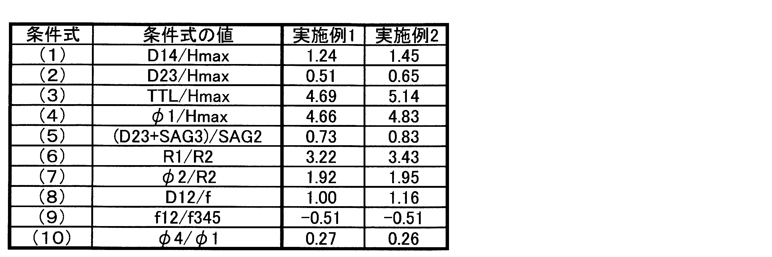
〔表7〕
〔第2実施形態〕
以下、第2実施形態の広角光学系等について説明する。なお、第2実施形態の広角光学系は第1実施形態の広角光学系を変形したものであり、特に説明しない事項は第1実施形態と同様である。
以下、第2実施形態の広角光学系等について説明する。なお、第2実施形態の広角光学系は第1実施形態の広角光学系を変形したものであり、特に説明しない事項は第1実施形態と同様である。
図4は、第2実施形態の広角光学系である撮像レンズ110を内蔵するレンズユニット40等を示す。この場合、第4レンズL4は、近軸で両凸形状を有する正の非球面レンズであり、第5レンズL5は、その物体側面が凹形状であり、近軸で像側に凸のメニスカス形状を有する負の非球面レンズである。第4及び第5レンズL4,L5をこのような構成とすることで、色収差の補正に関して有利である。第4レンズL4と第5レンズL5とは、両者を接合した構成とすることもできる。
以上、実施形態に即して広角光学系について説明したが、本発明に係る広角光学系は上記実施形態に限るものではなく様々な変形が可能である。
Claims (19)
- 物体側より順に、
物体側に凸形状で像側に凹形状を有するガラス製で両面ともに球面の負の第1レンズと、
少なくとも1面に非球面を有する像側に凹形状を有する負の第2レンズと、
正の第3レンズと、
絞りと、
少なくとも1面に非球面を有する第4レンズと、
少なくとも1面に非球面を有する第5レンズとから実質的になり、
下記条件式を満たす広角光学系。
1.10≦D14/Hmax≦1.80 … (1)
0.40≦D23/Hmax≦0.70 … (2)
4.0≦TTL/Hmax≦5.5 … (3)
4.0≦φ1/Hmax≦5.5 … (4)
ここで、
D14:前記第1レンズの物体側面から前記第2レンズの像側面までの光軸上の距離
D23:前記第1レンズの像側面から前記第2レンズの物体側面までの光軸上の距離
Hmax:最大像高
TTL:光学全長
φ1:前記第1レンズの物体側面の光学面径 - 下記条件式を満たす、請求項1に記載の広角光学系。
0.65≦(D23+SAG3)/SAG2≦1.0 … (5)
ここで、
D23:前記第1レンズの像側面から前記第2レンズの物体側面までの光軸上の距離
SAG2:前記第1レンズの像側面の光学面端におけるSAG量
SAG3:前記第2レンズの物体側面の光学面端でのSAG量 - 下記条件式を満たす、請求項1及び2のいずれか一項に記載の広角光学系。
3.0≦R1/R2≦3.5 … (6)
1.85≦φ2/R2≦1.95 … (7)
ここで、
R1:前記第1レンズの物体側面の曲率半径
R2:前記第1レンズの像側面の曲率半径
φ2:前記第1レンズの像側面の光学面径 - 下記条件式を満たす、請求項1~3のいずれか一項に記載の広角光学系。
0.8≦D12/f≦1.2 … (8)
ここで、
D12:前記第1レンズの中心厚
f:全系の焦点距離 - 前記第2レンズの像側面の有効径内の最大面角度が60°以上である、請求項1~4のいずれか一項に記載の広角光学系。
- 下記条件式を満たす、請求項1~5のいずれか一項に記載の広角光学系。
-0.6≦f12/f345≦-0.4 … (9)
ここで、
f12:前記第1及び第2レンズの合成焦点距離
f345:前記第3~第5レンズの合成焦点距離 - 全画角が160°以上である、請求項1~6のいずれか一項に記載の広角光学系。
- 前記第2~第5レンズはプラスチックレンズである、請求項1~7のいずれか一項に記載の広角光学系。
- 前記第2、第4及び第5レンズはプラスチックレンズであり、前記第3レンズはガラスレンズである、請求項1~7のいずれか一項に記載の広角光学系。
- 前記第2レンズの物体側面が凸形状である、請求項1~9のいずれか一項に記載の広角光学系。
- 前記第3レンズは少なくとも1面に非球面を有する両凸形状である、請求項1~10のいずれか一項に記載の広角光学系。
- 前記第4レンズは像側に凹形状を有する負レンズであり、前記第5レンズは両凸形状を有する正レンズであり、前記第4及び第5レンズは接合されている、請求項1~11のいずれか一項に記載の広角光学系。
- 前記第4レンズは両凸形状を有する正レンズであり、前記第5レンズは物体側に凹形状を有する負メニスカスレンズである、請求項1~11のいずれか一項に記載の広角光学系。
- 前記第4及び第5レンズは接合されている、請求項13に記載の広角光学系。
- 前記第5レンズは前記第4レンズのフランジ部と外周嵌合する構造となっている、請求項1~14のいずれか一項に記載の広角光学系。
- 前記第1レンズの物体側と前記第5レンズの像側とを除いたレンズ間対向面は光学面とは別の領域に形成され、光軸と略垂直なフランジ部で前後のレンズ、前記絞り、遮光部材、又はレンズホルダーのみと当接する、請求項1~15のいずれか一項に記載の広角光学系。
- 下記条件式を満たす、請求項1~16のいずれか一項に記載の広角光学系。
0.20≦φ4/φ1≦0.34 … (10)
ここで、
φ4:前記第2レンズの像側面の光学面径
φ1:前記第1レンズの物体側面の光学面径 - 請求項1~17のいずれか一項に記載の広角光学系と、
前記広角光学系を保持するレンズホルダーと
を備えるレンズユニット。 - 請求項18に記載のレンズユニットと、
前記レンズユニットによる像を投影する撮像素子と
を備える撮像装置。
Priority Applications (1)
| Application Number | Priority Date | Filing Date | Title |
|---|---|---|---|
| JP2018509276A JP6725888B2 (ja) | 2016-03-28 | 2017-03-24 | 広角光学系、レンズユニット及び撮像装置 |
Applications Claiming Priority (2)
| Application Number | Priority Date | Filing Date | Title |
|---|---|---|---|
| JP2016064549 | 2016-03-28 | ||
| JP2016-064549 | 2016-03-28 |
Publications (1)
| Publication Number | Publication Date |
|---|---|
| WO2017170284A1 true WO2017170284A1 (ja) | 2017-10-05 |
Family
ID=59965474
Family Applications (1)
| Application Number | Title | Priority Date | Filing Date |
|---|---|---|---|
| PCT/JP2017/012181 Ceased WO2017170284A1 (ja) | 2016-03-28 | 2017-03-24 | 広角光学系、レンズユニット及び撮像装置 |
Country Status (2)
| Country | Link |
|---|---|
| JP (1) | JP6725888B2 (ja) |
| WO (1) | WO2017170284A1 (ja) |
Cited By (5)
| Publication number | Priority date | Publication date | Assignee | Title |
|---|---|---|---|---|
| CN108646388A (zh) * | 2018-07-26 | 2018-10-12 | 协益电子(苏州)有限公司 | 车载镜头 |
| CN111538144A (zh) * | 2020-05-29 | 2020-08-14 | 宁波锦辉光学科技有限公司 | 一种超薄车载镜头 |
| JP2021005022A (ja) * | 2019-06-27 | 2021-01-14 | 日本電産サンキョー株式会社 | レンズユニット及びその製造方法 |
| US12044831B2 (en) | 2021-09-03 | 2024-07-23 | Canon Kabushiki Kaisha | Optical system having cemented lens including negative lens, image pickup apparatus, in-vehicle system, and moving apparatus |
| CN120085444A (zh) * | 2025-04-21 | 2025-06-03 | 浙江舜宇光学有限公司 | 光学成像镜头 |
Families Citing this family (1)
| Publication number | Priority date | Publication date | Assignee | Title |
|---|---|---|---|---|
| CN111856767B (zh) | 2019-04-24 | 2022-09-23 | 信泰光学(深圳)有限公司 | 测距仪及其显示器镜组装置 |
Citations (9)
| Publication number | Priority date | Publication date | Assignee | Title |
|---|---|---|---|---|
| JPS59202415A (ja) * | 1983-05-02 | 1984-11-16 | Olympus Optical Co Ltd | プラスチツクレンズとレンズ連結装置 |
| JP2003337271A (ja) * | 2002-05-21 | 2003-11-28 | Sony Corp | 結像レンズ装置及び撮像装置 |
| JP2006284620A (ja) * | 2005-03-31 | 2006-10-19 | Nidec Nissin Corp | 広角レンズおよび接合レンズ |
| JP2013174740A (ja) * | 2012-02-24 | 2013-09-05 | Hitachi Maxell Ltd | 広角レンズおよび撮像装置 |
| JP2013205715A (ja) * | 2012-03-29 | 2013-10-07 | Hitachi Maxell Ltd | 撮像レンズおよび撮像装置 |
| JP2014089241A (ja) * | 2012-10-29 | 2014-05-15 | Optical Logic Inc | 撮像レンズ |
| JP2014142542A (ja) * | 2013-01-25 | 2014-08-07 | Nidec Sankyo Corp | レンズユニットおよびレンズユニットの製造方法 |
| JP2015045803A (ja) * | 2013-08-29 | 2015-03-12 | サーテック インターナショナル (スツォウ) カンパニー リミテッドSirtec International(Suzhou)Co.,Ltd | 広角レンズ |
| WO2015159770A1 (ja) * | 2014-04-14 | 2015-10-22 | オリンパス株式会社 | カプセル型内視鏡 |
Family Cites Families (3)
| Publication number | Priority date | Publication date | Assignee | Title |
|---|---|---|---|---|
| US9007702B2 (en) * | 2013-03-03 | 2015-04-14 | Newmax Technology Co., Ltd. | Five-piece optical lens system |
| TWI479188B (zh) * | 2014-01-27 | 2015-04-01 | 玉晶光電股份有限公司 | 電子裝置與其光學成像鏡頭 |
| US10067315B2 (en) * | 2014-05-16 | 2018-09-04 | Sintai Optical (Shenzhen) Co., Ltd. | Lens assembly |
-
2017
- 2017-03-24 JP JP2018509276A patent/JP6725888B2/ja active Active
- 2017-03-24 WO PCT/JP2017/012181 patent/WO2017170284A1/ja not_active Ceased
Patent Citations (9)
| Publication number | Priority date | Publication date | Assignee | Title |
|---|---|---|---|---|
| JPS59202415A (ja) * | 1983-05-02 | 1984-11-16 | Olympus Optical Co Ltd | プラスチツクレンズとレンズ連結装置 |
| JP2003337271A (ja) * | 2002-05-21 | 2003-11-28 | Sony Corp | 結像レンズ装置及び撮像装置 |
| JP2006284620A (ja) * | 2005-03-31 | 2006-10-19 | Nidec Nissin Corp | 広角レンズおよび接合レンズ |
| JP2013174740A (ja) * | 2012-02-24 | 2013-09-05 | Hitachi Maxell Ltd | 広角レンズおよび撮像装置 |
| JP2013205715A (ja) * | 2012-03-29 | 2013-10-07 | Hitachi Maxell Ltd | 撮像レンズおよび撮像装置 |
| JP2014089241A (ja) * | 2012-10-29 | 2014-05-15 | Optical Logic Inc | 撮像レンズ |
| JP2014142542A (ja) * | 2013-01-25 | 2014-08-07 | Nidec Sankyo Corp | レンズユニットおよびレンズユニットの製造方法 |
| JP2015045803A (ja) * | 2013-08-29 | 2015-03-12 | サーテック インターナショナル (スツォウ) カンパニー リミテッドSirtec International(Suzhou)Co.,Ltd | 広角レンズ |
| WO2015159770A1 (ja) * | 2014-04-14 | 2015-10-22 | オリンパス株式会社 | カプセル型内視鏡 |
Cited By (6)
| Publication number | Priority date | Publication date | Assignee | Title |
|---|---|---|---|---|
| CN108646388A (zh) * | 2018-07-26 | 2018-10-12 | 协益电子(苏州)有限公司 | 车载镜头 |
| JP2021005022A (ja) * | 2019-06-27 | 2021-01-14 | 日本電産サンキョー株式会社 | レンズユニット及びその製造方法 |
| JP7201543B2 (ja) | 2019-06-27 | 2023-01-10 | 日本電産サンキョー株式会社 | レンズユニット及びその製造方法 |
| CN111538144A (zh) * | 2020-05-29 | 2020-08-14 | 宁波锦辉光学科技有限公司 | 一种超薄车载镜头 |
| US12044831B2 (en) | 2021-09-03 | 2024-07-23 | Canon Kabushiki Kaisha | Optical system having cemented lens including negative lens, image pickup apparatus, in-vehicle system, and moving apparatus |
| CN120085444A (zh) * | 2025-04-21 | 2025-06-03 | 浙江舜宇光学有限公司 | 光学成像镜头 |
Also Published As
| Publication number | Publication date |
|---|---|
| JP6725888B2 (ja) | 2020-07-22 |
| JPWO2017170284A1 (ja) | 2019-02-07 |
Similar Documents
| Publication | Publication Date | Title |
|---|---|---|
| CN111045191B (zh) | 光学系统、透镜单元以及摄像装置 | |
| US9442278B2 (en) | Zoom lens and imaging apparatus | |
| CN100507631C (zh) | 广角摄像透镜、摄像装置、及摄像机组件 | |
| JP6614337B2 (ja) | 広角光学系、レンズユニット及び撮像装置 | |
| JP6725888B2 (ja) | 広角光学系、レンズユニット及び撮像装置 | |
| JP6525144B2 (ja) | 広角レンズ、レンズユニット、及び撮像装置 | |
| JPWO2013027641A1 (ja) | 撮像レンズ及び撮像装置 | |
| CN104603663B (zh) | 广角透镜及摄像装置 | |
| CN110297305B (zh) | 光学系统、透镜单元以及拍摄装置 | |
| WO2013099214A1 (ja) | 撮像レンズおよび撮像装置 | |
| JP6721865B2 (ja) | 撮像レンズ、レンズユニット、及び撮像装置 | |
| JP2019168491A (ja) | 広角レンズ、レンズユニット、及び撮像装置 | |
| WO2018097287A1 (ja) | 撮像光学系、レンズユニット、及び撮像装置 | |
| JP2009145597A (ja) | 撮像レンズ、撮像ユニット、及び該撮像ユニットを搭載した携帯型情報端末 | |
| WO2013027350A1 (ja) | 撮像レンズおよびこれを用いた撮像装置 | |
| JP2013024892A (ja) | 撮像レンズ及び撮像装置 | |
| JP2019124744A (ja) | 撮像光学系及び撮像装置 | |
| CN105190393A (zh) | 广角透镜及摄像装置 | |
| JP2009008956A (ja) | 撮像レンズ体、撮像ユニット、及び該撮像ユニットを搭載した携帯型情報端末 | |
| JP4953953B2 (ja) | 撮像レンズ、およびカメラモジュールならびに携帯端末機器 | |
| CN108885330B (zh) | 摄像透镜、透镜单元以及摄像装置 | |
| JP5589509B2 (ja) | 光学ユニットおよび撮像装置 | |
| JP2011081102A (ja) | 光学ユニットおよび撮像装置 | |
| WO2013099212A1 (ja) | 撮像レンズおよび撮像装置 | |
| JP5963003B2 (ja) | 撮像レンズ及び撮像装置 |
Legal Events
| Date | Code | Title | Description |
|---|---|---|---|
| WWE | Wipo information: entry into national phase |
Ref document number: 2018509276 Country of ref document: JP |
|
| NENP | Non-entry into the national phase |
Ref country code: DE |
|
| 121 | Ep: the epo has been informed by wipo that ep was designated in this application |
Ref document number: 17774821 Country of ref document: EP Kind code of ref document: A1 |
|
| 122 | Ep: pct application non-entry in european phase |
Ref document number: 17774821 Country of ref document: EP Kind code of ref document: A1 |