WO2017170226A1 - 旋回フレーム、およびこれを備えた建設機械 - Google Patents
旋回フレーム、およびこれを備えた建設機械 Download PDFInfo
- Publication number
- WO2017170226A1 WO2017170226A1 PCT/JP2017/012016 JP2017012016W WO2017170226A1 WO 2017170226 A1 WO2017170226 A1 WO 2017170226A1 JP 2017012016 W JP2017012016 W JP 2017012016W WO 2017170226 A1 WO2017170226 A1 WO 2017170226A1
- Authority
- WO
- WIPO (PCT)
- Prior art keywords
- bottom plate
- bearing
- swivel frame
- fixed
- wall
- Prior art date
- Legal status (The legal status is an assumption and is not a legal conclusion. Google has not performed a legal analysis and makes no representation as to the accuracy of the status listed.)
- Ceased
Links
Images


Classifications
-
- B—PERFORMING OPERATIONS; TRANSPORTING
- B66—HOISTING; LIFTING; HAULING
- B66C—CRANES; LOAD-ENGAGING ELEMENTS OR DEVICES FOR CRANES, CAPSTANS, WINCHES, OR TACKLES
- B66C23/00—Cranes comprising essentially a beam, boom, or triangular structure acting as a cantilever and mounted for translatory of swinging movements in vertical or horizontal planes or a combination of such movements, e.g. jib-cranes, derricks, tower cranes
- B66C23/18—Cranes comprising essentially a beam, boom, or triangular structure acting as a cantilever and mounted for translatory of swinging movements in vertical or horizontal planes or a combination of such movements, e.g. jib-cranes, derricks, tower cranes specially adapted for use in particular purposes
- B66C23/36—Cranes comprising essentially a beam, boom, or triangular structure acting as a cantilever and mounted for translatory of swinging movements in vertical or horizontal planes or a combination of such movements, e.g. jib-cranes, derricks, tower cranes specially adapted for use in particular purposes mounted on road or rail vehicles; Manually-movable jib-cranes for use in workshops; Floating cranes
-
- B—PERFORMING OPERATIONS; TRANSPORTING
- B66—HOISTING; LIFTING; HAULING
- B66C—CRANES; LOAD-ENGAGING ELEMENTS OR DEVICES FOR CRANES, CAPSTANS, WINCHES, OR TACKLES
- B66C23/00—Cranes comprising essentially a beam, boom, or triangular structure acting as a cantilever and mounted for translatory of swinging movements in vertical or horizontal planes or a combination of such movements, e.g. jib-cranes, derricks, tower cranes
- B66C23/62—Constructional features or details
- B66C23/84—Slewing gear
-
- E—FIXED CONSTRUCTIONS
- E02—HYDRAULIC ENGINEERING; FOUNDATIONS; SOIL SHIFTING
- E02F—DREDGING; SOIL-SHIFTING
- E02F9/00—Component parts of dredgers or soil-shifting machines, not restricted to one of the kinds covered by groups E02F3/00 - E02F7/00
- E02F9/08—Superstructures; Supports for superstructures
- E02F9/10—Supports for movable superstructures mounted on travelling or walking gears or on other superstructures
- E02F9/12—Slewing or traversing gears
Definitions
- the present invention relates to a revolving frame and a construction machine equipped with the same.
- Patent Document 1 describes a conventional crane turning frame. Bearings are attached to the bottom plate of the swivel frame with bolts.
- a tensile axial force acts on the bolt that fixes the rear portion of the bearing and the bottom plate of the swivel frame.
- the tensile axial force acting on the bolt locally increases in the vicinity of the joint portion between the side plate and the bottom plate of the swivel frame. For example, if a tensile axial force repeatedly acts on the bolt, the bolt may be damaged. In addition, for example, it may be necessary to limit the crane's lifting capacity so that the bolt is not damaged.
- an object of the present invention is to provide a turning frame capable of reducing the maximum value of the axial force applied to the bolt for fixing the bearing, and a construction machine equipped with the same.
- the turning frame of the present invention is supported by a lower traveling body of a construction machine via a bearing so that the turning frame can turn around a turning center extending in the vertical direction.
- the swivel frame includes a bottom plate, a plurality of side plates, a wall portion, at least one connecting member, and a pressing member.
- the bottom plate has an upper surface portion and a lower surface portion to which the bearing is fixed.
- a plurality of bolt holes for receiving a plurality of bolts for fixing the bottom plate and the bearing along the vertical direction are arranged in an arc shape around the turning center as seen from the vertical direction.
- the plurality of side plates extend along the front-rear direction of the swivel frame, and are respectively disposed on the upper surface portion of the bottom plate so as to face each other across the swivel center in the left-right direction of the swivel frame.
- the wall portion is fixed to the bottom plate so as to extend upward from the upper surface portion of the bottom plate. Further, the wall portion is disposed so as to be along the plurality of the bolt holes when viewed from the up-down direction, behind the turning center and on the radially outer side of the bearing from the plurality of bolt holes.
- the connecting member is disposed so as to extend rearward and outward in the left-right direction from the wall portion, and connects the wall portion and the side plate.
- the pressing member is fixed to the wall portion and the connecting member so as to cover the wall portion and the connecting member from above.
- the above configuration can reduce the maximum value of the axial force applied to the plurality of bolts that fix the swing frame and the bearing.
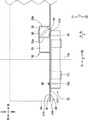
- FIG. 1 is a side view of a construction machine according to an embodiment of the present invention. It is a side view of the turning frame of the construction machine shown in FIG. It is a top view of the turning frame of the construction machine shown in FIG.
- a crane 1 construction machine including a turning frame 30 according to an embodiment of the present invention will be described with reference to FIGS. 1 to 3.
- the crane 1 is a construction machine that performs the work of lifting the suspended load L by the boom 21 and is a mobile crane.
- the crane 1 includes a lower traveling body 11, a bearing 13, and an upper swing body 20.
- the lower traveling body 11 is a part that causes the crane 1 to travel.
- the bearing 13 is provided between the lower traveling body 11 and the upper swing body 20.
- the bearing 13 supports the upper swing body 20 so that the upper swing body 20 can swing with respect to the lower traveling body 11 around a swing center 13c extending in the vertical direction.
- the bearing 13 is annular.
- the radial direction of the bearing 13 is defined as “bearing radial direction”.
- the bearing radial direction is a virtual circle on a plane orthogonal to the turning center 13c and is a diameter direction of a virtual circle centered on the turning center 13c. In the bearing radial direction, the direction (outward) from the turning center 13c toward the outer periphery of the bearing 13 is defined as outward in the bearing radial direction. As shown in FIG.
- the bearing 13 includes an inner race 13i and an outer race 13o.
- the inner race 13i is fixed to the lower traveling body 11 (see FIG. 1).
- the outer race 13o is disposed outside the inner race 13i in the bearing radial direction.
- the outer race 13o is attached to the inner race 13i so that the outer race 13o can turn with respect to the inner race 13i around the turning center 13c.
- the outer race 13o is fixed to the upper swing body 20 by a plurality of bolts 45 described later.
- the relationship between the inner race 13i and the outer race 13o does not have to be the above-described mode.
- the outer race 13o is fixed to the lower traveling body 11 (see FIG. 1), and the inner race 13i is turned upward by a plurality of bolts 45. It may be fixed to the body 20.
- a mode in which the outer race 13o is fixed to the upper swing body 20 will be described.
- the upper revolving unit 20 is attached to the lower traveling unit 11 via a bearing 13 and supported by the lower traveling unit 11 as shown in FIG.
- the upper swing body 20 includes a work device 1S and a swing frame 30 (FIG. 1).
- the work device 1S includes a boom 21, a guy line 22, a mast 23, a hoisting rope 24, and a lower spreader 25, and executes a predetermined lifting work.
- the boom 21 is attached to the revolving frame 30 so as to be raised and lowered.
- the mast 23 is a member that supports the boom 21 from the rear side, and is attached to the revolving frame 30 so as to be raised and lowered.
- a guy line 22 is connected to the tip of the mast 23 and the tip of the boom 21.
- the lower spreader 25 is attached to the rear portion of the turning frame 30.
- the hoisting rope 24 is wound around the lower spreader 25 and the tip of the mast 23 (upper spreader). As the hoisting rope 24 is wound and unwound by a winch (not shown), the boom 21 is raised and lowered as a result of the mast 23 being raised and lowered.
- the mast 23 is fixed to the revolving frame 30, and an upper and lower spreader (not shown) (an upper spreader and a lower spreader) are arranged between the mast 23 and the boom 21, and the distance between the upper and lower spreaders is changed. Thus, the boom 21 may be raised and lowered.
- the turning frame 30 is a frame (structure) to which the boom 21 and the like are attached.
- the turning frame 30 includes a boom foot 31, a mast foot 33, and a lower spreader foot 35.
- the base end portion of the boom 21 is attached to the boom foot 31.
- the base end portion of the mast 23 is attached to the mast foot 33.
- a lower spreader 25 is attached to the lower spreader foot 35.
- the swivel frame 30 has a longitudinal direction.
- the longitudinal direction of the turning frame 30 is defined as the front-rear direction (X).
- the mast foot 33 is disposed between the boom foot 31 and the lower spreader 35 in the front-rear direction.
- the lower spreader 35 is disposed on the same side as the vertical plate 51 described later in the front-rear direction when viewed from the turning center 13c.
- a direction from the lower spreader foot 35 to the boom foot 31 is defined as a front direction (X1), and the opposite direction is defined as a rear direction (X2).
- a horizontal direction orthogonal to the front-rear direction of the turning frame 30 is defined as a lateral direction (Y) (also referred to as a left-right direction of the turning frame 30). As shown in FIG.
- a direction approaching the lateral center of the swivel frame 30 is defined as lateral inward (Y1) (also referred to as lateral inward), and the lateral center of the swivel frame 30 is defined.
- the direction away from the head is defined as lateral outward (Y2) (also referred to as lateral outward).
- Y1 lateral inward
- Y2 lateral outward
- Z1 upward direction
- Z2 the opposite direction
- the revolving frame 30 includes a bottom plate 41, a pair (a plurality) of side plates 43, a plurality of bolts 45, and a bolt axial force averaging structure 50.
- the side plate 43 is indicated by a virtual line (two-dot chain line).
- the bottom plate 41 is provided in the lower part of the revolving frame 30.
- the bottom plate 41 is a plate-like member extending in the front-rear direction and the lateral direction, and may be a substantially plate-like member.
- the point which may be substantially plate-shaped is also the same for the following “plate-shaped”.
- the bottom plate 41 includes an upper surface portion 41A and a lower surface portion 41B (FIG. 2).
- the bearing 13 is attached and fixed to the lower surface portion 41 ⁇ / b> B of the bottom plate 41. Specifically, the upper surface portion of the outer race 13 o of the bearing 13 is fixed to the lower surface portion 41 B of the bottom plate 41.
- the pair of side plates 43 is a member extending upward from the upper surface portion 41A of the bottom plate 41, and extends upward from the laterally outer end portion of the bottom plate 41 as shown in FIG.
- the side plate 43 is a plate-like member extending in the up-down direction and the front-rear direction.
- the pair of side plates 43 are disposed so as to face each other across the turning center 13c in the lateral direction (FIG. 3).
- the number of side plates 43 may exceed two.
- the plurality of bolts 45 fix the bottom plate 41 and the bearing 13 (outer race 13o) along the vertical direction.
- the plurality of bolts 45 are arranged in a substantially circumferential shape centered on the turning center 13 c when viewed from the up-down direction.
- the plurality of bolts 45 on the rear side of the turning center 13c are arranged in a substantially arc shape centered on the turning center 13c when viewed from the vertical direction.
- only some of the plurality of bolts 45 are denoted by reference numerals.
- the bottom plate 30 has a plurality of bolt holes 45S for receiving the plurality of bolts 45, respectively.
- the plurality of bolt holes 45S are also arranged (arranged) in a substantially circumferential shape centered on the turning center 13c when viewed from the vertical direction.
- the plurality of bolt holes 45S on the rear side of the turning center 13c are arranged in a substantially arc shape with the turning center 13c as the center when viewed from the vertical direction. It is out.
- only some of the plurality of bolt holes 45 ⁇ / b> S are denoted by reference numerals.
- the bolt axial force averaging structure 50 is a structure for averaging the tensile axial force acting on each of the plurality of bolts 45 as much as possible.
- the bolt axial force averaging structure 50 includes a vertical plate 51 (wall portion), a pair of connecting members 53, and a pressing member 55.
- the vertical plate 51 is a plate-like member that extends upward from the upper surface portion 41 ⁇ / b> A of the bottom plate 41.
- the vertical plate 51 is disposed on the rear side of the turning center 13 c of the bearing 13. In the example shown in FIG. 3, the entire vertical plate 51 is disposed on the rear side of the turning center 13 c. A part of the vertical plate 51 may be arranged behind the turning center 13c, and a main part of the vertical plate 51 may be arranged behind the turning center 13c.
- the vertical plate 51 includes an inner wall surface 51A facing the turning center 13c and an outer wall surface 51B opposite to the inner wall surface 51A (FIG. 3).
- the lower end portion of the vertical plate 51 is fixed to the bottom plate 41.
- This fixing is, for example, fixing by welding.
- the point that the fixing is fixing by welding for example, is the same for fixing the other part of the vertical plate 51, fixing the connection member 53, and fixing the pressing member 55.
- the vertical plate 51 is disposed on the radially outer side of the bearing 13 with respect to the plurality of bolts 45 (a plurality of bolt holes 45S).
- the vertical plate 51 is disposed in the vicinity of the plurality of bolts 45.
- the vertical plate 51 is arranged so as to be aligned (along) with a plurality of bolts 45 (bolt holes 45S) arranged in an arc shape when viewed in the vertical direction.
- the vertical plate 51 is arranged in a curved or substantially curved shape.
- the vertical plate 51 is arranged in an arc shape or a substantially arc shape with the turning center 13c as a substantially center (or the center, the same applies hereinafter).
- the vertical plate 51 when viewed from the vertical direction, may be arranged in a semicircular shape or a substantially semicircular shape with the turning center 13c as a center, or may be arranged in a U shape or a substantially U shape. Good.
- the substantially arc shape, substantially semicircular shape, substantially U shape, and substantially curved shape described above may be formed in a polygonal line shape (not shown), for example.
- the above-mentioned polygonal line shape is, for example, a shape formed by connecting a plurality of linear (or curved) members as viewed from the up-down direction.
- the vertical plate 51 is preferably fixed to each of the two side plates 43. Specifically, both end portions 51 ⁇ / b> S (FIG.
- a plate-like member similar to the vertical plate 51 may be provided in front of the turning center 13c.
- the plate-like member similar to the vertical plate 51 and the vertical plate 51 have a circumferential shape so as to surround substantially the entire circumference (or the entire circumference) of the bolts 45 arranged in a substantially circumferential shape.
- the above elliptical circumference is the shape of the circumference of the ellipse.
- the vertical plate 51 is disposed on the side opposite to the boom 21 when viewed from the turning center 13c.
- the pair of connecting members 53 are members that connect the vertical plate 51 and the pair of side plates 43.
- the connecting member 53 has a plate shape. When viewed from the thickness direction of the connecting member 53, the connecting member 53 is a quadrangle, for example, a rectangle.
- the connecting member 53 is disposed on the rear side of the turning center 13c.
- the connecting members 53 are provided on both sides (right side and left side) that are straight lines passing through the turning center 13c and laterally outside the straight line extending in the front-rear direction.
- the connecting member 53 is provided on both side portions (the right side portion and the left side portion) on the laterally outer side of the revolving frame 30. Note that it is sufficient that at least two connecting members 53 are provided in total, and three or more connecting members 53 may be provided.
- Each of the two connecting members 53 is configured as follows.
- the joint between the front end of the connecting member 53 and the vertical plate 51 is defined as a front joint 53a.
- the front joint portion 53 a is provided (arranged) in a portion of the vertical plate 51 that is laterally inner than the side plate 43.
- the front joint portion 53a is disposed in a portion of the outer wall surface 51B of the vertical plate 51 that is away from the left and right end portions 51S of the vertical plate 51 in the left-right direction.
- the front joint 53 a is provided continuously from the upper end to the lower end of the vertical plate 51.
- the front side joining part 53a may be provided only in the upper part of the vertical plate 51, and may be provided only in the lower part of the vertical plate 51. As shown in FIG.
- a joint portion between the rear end portion of the connecting member 53 and the side plate 43 is defined as a rear joint portion 53 b.
- the vertical width of the rear joint 53b is the same as the vertical width of the front joint 53a.
- the lower end of the connecting member 53 is fixed to the bottom plate 41.
- the lower end portion of the connecting member 53 is fixed to the bottom plate 41 from the front joint portion 53a to the rear joint portion 53b. Only the rear portion (laterally outer portion) of the connecting member 53 may be fixed to the bottom plate 41.
- the connecting member 53 may be provided only in the range A1 of FIG.
- the connecting member 53 may be rod-shaped or substantially rod-shaped.
- the connecting member 53 extends rearward and laterally outward from the front joint portion 53a.
- the connecting member 53 extends so as to be inclined with respect to the front-rear direction and the lateral direction so that the rear side is disposed on the outer side in the lateral direction.
- the connecting member 53 extends in a direction orthogonal or substantially orthogonal to the vertical plate 51 in the front-side joint portion 53a.
- the pressing member 55 is fixed to the vertical plate 51 and the connecting member 53 so as to cover the vertical plate 51 and the connecting member 53 from above.
- the pressing member 55 is fixed to the upper end of the vertical plate 51 and the upper end of the connecting member 53.
- the pressing member 55 covers at least the pair of front side joint portions 53a from above.
- the pressing member 55 has a plate shape extending in the lateral direction and the front-rear direction.
- the pressing member 55 is rectangular and may be a rectangle other than the rectangle, for example, a trapezoid shown in a range A2 in FIG.
- the pressing member 55 may have a shape other than a quadrangle having an outer periphery constituted by a curve or a straight line, for example, a polygon other than a quadrangle, for example, an oval or a substantially oval. .
- the pressing member 55 may have any shape as long as it is fixed to the upper end of the vertical plate 51 and the upper end of the connecting member 53.
- the pressing member 55 may be one or a plurality of rods and extend in the lateral direction.
- the pressing member 55 may be in the form of one or a plurality of blocks and extend in the lateral direction.
- the position in the front-rear direction of the front end portion of the pressing member 55 is, for example, substantially the same position as the front-side joint portion 53a (see range A2), and is preferably in front of the front-side joint portion 53a. Further, the position in the front-rear direction of the front end of the pressing member 55 may be substantially the same as the position in the front-rear direction of the front end of the vertical plate 51, or may be in front of the front end of the vertical plate 51. In addition, the position in the front-rear direction of the front end portion of the pressing member 55 is preferably behind the front end portion of the vertical plate 51 from the viewpoint of mass suppression of the pressing member 55.
- the position of the rear end portion of the pressing member 55 in the front-rear direction may be substantially the same position as the front joint portion 53a, or may be the same position as the position of the rear end portion of the vertical plate 51 in the front-rear direction (see range A2).
- the rear side of the rear end of the vertical plate 51 may be used.
- the position in the front-rear direction of the rear end portion of the pressing member 55 may be substantially the same position as the position in the front-rear direction of the rear joint portion 53b.
- the position in the front-rear direction of the rear end portion of the pressing member 55 is preferably on the front side of the rear side joining portion 53b from the viewpoint of mass suppression of the pressing member 55.
- the pressing member 55 is fixed to the two side plates 43. That is, both end portions 55 ⁇ / b> S (FIG. 3) on the laterally outer side of the pressing member 55 are respectively fixed to the side plates 43.
- the pressing member 55 does not have to be fixed to the side plate 43.
- the laterally outer end portion of the pressing member 55 may be disposed between the front joint portion 53a and the side plate 43 (between in the lateral direction) (see range A2).
- Compressive force f3 and compressive force f7 generated in the front portion 30A (FIG. 1) of the turning frame 30 cause a compressive load f21 (downward force) to act on the front portion of the bearing 13 relative to the turning center 13c.
- This compressive load f21 is carried by the upper surface of the bearing 13.
- the bending load f11 generated in the rear portion 30B (FIG. 1) of the swing frame 30 applies a tensile load f22 (upward force) to a portion of the bearing 13 that is behind the swing center 13c. With this tensile load f22, the bottom plate 41 and the bearing 13 tend to be separated from each other in the vertical direction.
- This tensile load f22 is carried by the bolt 45 shown in FIG.
- the tensile axial force acts on the bolt 45 (hereinafter, the tensile axial force is referred to as an axial force).
- the position of the neutral shaft of the bearing 13 shown in FIG. 1 (the position where neither the compression load f21 nor the tensile load f22 is applied) varies somewhat depending on the work situation (the mass of the suspended load L, the undulation angle of the boom 21, etc.).
- the position of the neutral axis of the bearing 13 and the position of the turning center 13c substantially coincide.
- the bolt axial force averaging structure 50 shown in FIG. 3 is not provided, the axial force applied to the bolt 45 in the vicinity of the side plate 43 is the largest, and the axial force applied to the bolt 45 on the inner side in the lateral direction from the side plate 43 is smaller. Become.
- the force is transmitted as follows.
- the upward force (see the bending load f11 shown in FIG. 1) is transmitted from the side plate 43 and the bottom plate 41 to the connecting member 53.
- This force is a portion of the vertical plate 51 away from the side plate 43 inward in the lateral direction, a portion of the bottom plate 41 away from the side plate 43 inward in the lateral direction, and a position away from the side plate 43 inward in the lateral direction.
- the bolts 45 (the bolts 45 in the central region near the straight line extending in the front-rear direction through the turning center 13c) are transmitted in this order.
- the axial force applied to the bolt 45 in the vicinity of the side plate 43 is smaller than that in the case where the bolt axial force averaging structure 50 is not provided, and the position is located in the vicinity of the central portion in the horizontal direction of the bottom plate 41 in the lateral direction from the side plate 43.
- the axial force applied to the bolt 45 to be increased. Therefore, the minimum value of the axial force applied to the plurality of bolts 45 is increased, and the maximum value of the axial force applied to the plurality of bolts 45 is decreased. That is, the axial force applied to the plurality of bolts 45 is averaged (approached to the average value and leveled).
- the present embodiment including the bolt axial force averaging structure 50 and a comparative example not including the bolt axial force averaging structure 50 were compared as follows.
- the total axial force value of all the bolts 45 attached to the rear half of the bearing 13 (see FIG. 2) and acting on the tensile axial force is defined as ⁇ .
- the axial force (peak axial force) of the bolt 45 on which the highest tensile axial force acts is defined as ⁇ .
- the ratio of the peak axial force ⁇ to the total axial force value ⁇ that is, the value obtained by dividing the peak axial force ⁇ by the total axial force value ⁇ ( ⁇ / ⁇ ) was obtained and compared for each of the present embodiment and the comparative example.
- ⁇ / ⁇ of the comparative example was 100%
- ⁇ / ⁇ of the present embodiment was 94%. Therefore, it became clear that the axial force of tension acting on the plurality of bolts 45 of this embodiment was dispersed compared to the comparative example.
- the bearing 13 is fixed to the turning frame 30.
- the turning frame 30 has a shape that is long in the front-rear direction.
- the revolving frame 30 includes a bottom plate 41, two side plates 43, a plurality of bolts 45, a vertical plate 51, a pair of connecting members 53, and a pressing member 55.
- the bearing 13 is fixed to the bottom plate 41.
- the two side plates 43 extend upward from the bottom plate 41 and face each other in the lateral direction.
- the plurality of bolts 45 fix the bottom plate 41 and the bearing 13 along the vertical direction.
- the vertical plate 51 is fixed to the bottom plate 41, extends upward from the bottom plate 41, and is disposed on the rear side of the turning center 13c of the bearing 13 as shown in FIG.
- the vertical plate 51 is disposed on the radially outer side of the bearing 13 with respect to the plurality of bolts 45 (the plurality of bolt holes 45S).
- the vertical plate 51 is arranged so as to be lined up with a plurality of bolts 45 arranged in an arc shape when viewed from the vertical direction.
- the connecting member 53 extends rearward and laterally outward from a portion of the vertical plate 51 that is spaced laterally inner than the side plate 43, and is fixed to the side plate 43.
- the pressing member 55 is fixed to the vertical plate 51 and the connecting member 53 so as to cover at least the connecting portion (53a) of the vertical plate 51 and the connecting member 53 from above.
- the upward force applied to the rear portion 30 ⁇ / b> B of the turning frame 30 is laterally inward from the side plate 43 of the bottom plate 41 through the connecting member 53 and the vertical plate 51 from the side plate 43. It is transmitted to the part far away. Therefore, as compared with the case where the vertical plate 51 and the connecting member 53 are not provided, the axial force applied to the bolt 45 (the bolt 45 near the center in the horizontal direction) that is located inward in the horizontal direction from the side plate 43 increases. The axial force applied to the bolt 45 near 43 becomes small. Therefore, the axial force applied to the plurality of bolts 45 can be averaged. As a result, the maximum value of the axial force applied to the plurality of bolts 45 for fixing the bearing 13 can be reduced.
- the vertical plate 51 is arranged so as to be lined up with a plurality of bolts 45 arranged in an arc shape when viewed from above and below. For this reason, the force transmitted from the vertical plate 51 to the bolt 45 can be easily distributed to the plurality of bolts 45. Therefore, the maximum value of the axial force applied to the bolt 45 can be further reduced.
- the pressing member 55 is fixed to the vertical plate 51 and the connecting member 53 so as to cover at least the connecting portion of the vertical plate 51 and the connecting member 53 from above. For this reason, compared with the case where the pressing member 55 is not provided, the force is easily transmitted from the connecting member 53 to the vertical plate 51. As a result, the force is easily transmitted from the side plate 43 to the plurality of bolts 45 near the central portion in the lateral direction. Therefore, the maximum value of the axial force applied to the plurality of bolts 45 can be further reduced.
- the maximum value of the axial force applied to the plurality of bolts 45 can be reduced, so that breakage of the bolts 45 can be suppressed. Moreover, when the lifting capacity of the crane 1 is limited by the maximum value of the axial force applied to the bolt 45, the lifting capacity of the crane 1 can be increased as a result of the reduction of the maximum value of the axial force applied to the bolt 45.
- the vertical plate 51 is fixed to the two side plates 43, respectively. For this reason, force is transmitted from the two side plates 43 to the vertical plate 51. Therefore, force is easily transmitted from the side plate 43 to the plurality of bolts 45 on the inner side in the lateral direction than the side plate 43 through the vertical plate 51. Therefore, the maximum value of the axial force applied to the bolt 45 can be further reduced.
- the rear portion of the connecting member 53 is fixed to the bottom plate 41.
- the connecting member 53 extends rearward and laterally outward from a portion of the vertical plate 51 that is spaced laterally inward from the side plate 43, and is fixed to the side plate 43. . Accordingly, the force is transmitted from the bottom plate 41 in the vicinity of the side plate 43 shown in FIG. 3 to the rear portion of the connecting member 53 and is transmitted to the front portion of the connecting member 53.
- force can be transmitted from the bottom plate 41 in the vicinity of the side plate 43 to the plurality of bolts 45 on the inner side in the lateral direction than the side plate 43 via the connecting member 53 and the vertical plate 51. Therefore, the axial force applied to the bolt 45 near the side plate 43 can be further reduced. Therefore, the maximum value of the axial force applied to the bolt 45 can be reduced.
- the pressing member 55 is fixed to the two side plates 43, respectively. For this reason, force is transmitted from the two side plates 43 to the pressing member 55. Therefore, force is easily transmitted from the side plate 43 to the plurality of bolts 45 on the inner side in the lateral direction than the side plate 43 through the pressing member 55 and the vertical plate 51. Therefore, the maximum value of the axial force applied to the bolt 45 can be further reduced.
- the above embodiment may be variously modified. Some of the components of the above embodiment may not be provided, and the number of components may be changed.
- the two connecting members 53 are provided. However, one or three or more connecting members 53 may be provided. Further, both end portions 51 ⁇ / b> S (FIG. 3) of the vertical plate 51 may not be fixed to the side plate 43. Further, the lower end portion of the connecting member 53 shown in FIG. 2 may not be fixed to the bottom plate 41. Both end portions 55 ⁇ / b> S of the pressing member 55 shown in FIG. 3 may not be fixed to the side plate 43.
Landscapes
- Engineering & Computer Science (AREA)
- Mechanical Engineering (AREA)
- Mining & Mineral Resources (AREA)
- Civil Engineering (AREA)
- General Engineering & Computer Science (AREA)
- Structural Engineering (AREA)
- Jib Cranes (AREA)
Abstract
旋回フレーム30とベアリング13とを固定するためのボルトにかかる軸力の最大値を低減する。縦板51は、ベアリング13の旋回中心13cよりも後側に配置され、ボルト45よりもベアリング13の径方向外側に配置される。縦板51は、上下方向から見て円弧状に配列される複数のボルト45に沿うように配置される。連結部材53は、縦板51の該壁面51Bから、後方かつ横方向外側に延び、側板43に固定される。押さえ部材55は、縦板51および連結部材53を上側から覆うように、縦板51および連結部材53に固定される。
Description
本発明は、旋回フレーム、およびこれを備えた建設機械に関する。
特許文献1には、従来のクレーンの旋回フレームが記載されている。旋回フレームの底板に、ベアリングがボルトによって取り付けられる。
上記のような技術では、クレーンの作業時などに、旋回フレームの後側部分が引き上げられる。そのため、ベアリングの後側部分と旋回フレームの底板とを固定するボルトに、引張の軸力が作用する。ボルトに作用する引張の軸力は、旋回フレームの側板と底板との接合部分の近傍で、局所的に大きくなる。例えば、ボルトに引張の軸力が繰り返し作用すると、ボルトが破損するおそれがある。また、例えば、ボルトが破損しないように、クレーンの吊能力を制限する必要が生じる場合がある。
そこで本発明の目的は、ベアリングを固定するためのボルトにかかる軸力の最大値を低減できる旋回フレーム、およびこれを備えた建設機械を提供することにある。
本発明の旋回フレームは、上下方向に延びる旋回中心回りに旋回可能なように、建設機械の下部走行体にベアリングを介して支持される。旋回フレームは、底板と、複数の側板と、壁部と、少なくとも一つの連結部材と、押さえ部材と、を備える。底板は、上面部と前記ベアリングが固定される下面部とを有する。底板には、前記底板と前記ベアリングとを上下方向に沿って固定する複数のボルトをそれぞれ受け入れる複数のボルト穴が上下方向から見て前記旋回中心回りに円弧状に配列されている。複数の側板は、前記旋回フレームの前後方向に沿ってそれぞれ延びるとともに、前記旋回フレームの左右方向において前記旋回中心を挟んで互いに対向するように前記底板の前記上面部にそれぞれ配置される。壁部は、前記底板の前記上面部から上方に延びるように前記底板に固定される。また、壁部は、前記旋回中心よりも後方かつ前記複数のボルト穴よりも前記ベアリングの径方向外側において、上下方向から見て前記複数の前記ボルト穴に沿うように配置される。連結部材は、前記壁部から後方かつ前記左右方向の外側に向かって延びるように配置され、前記壁部と前記側板とを連結する。押さえ部材は、前記壁部と前記連結部材とを上方から覆うように、前記壁部および前記連結部材に固定される。
上記構成により、旋回フレームとベアリングとを固定する複数のボルトにかかる軸力の最大値を低減することができる。
図1~図3を参照して本発明の一実施形態に係る旋回フレーム30を備えるクレーン1(建設機械)について説明する。
クレーン1は、ブーム21により吊荷Lを吊り上げる作業などを行う建設機械であり、移動式クレーンである。クレーン1は、下部走行体11と、ベアリング13と、上部旋回体20と、を備える。下部走行体11は、クレーン1を走行させる部分である。
ベアリング13は、下部走行体11と上部旋回体20との間に設けられる。ベアリング13は、上下方向に延びる旋回中心13cを中心に下部走行体11に対して上部旋回体20が旋回自在となるように、上部旋回体20を支持する。ベアリング13は、円環状である。ベアリング13の径方向を「ベアリング径方向」と定義する。ベアリング径方向は、旋回中心13cに直交する平面上の仮想円であって旋回中心13cを中心とする仮想円の直径方向である。ベアリング径方向において、旋回中心13cからベアリング13の外周部に向かう向き(外向き)をベアリング径方向外向きと定義する。図2に示すように、ベアリング13は、インナーレース13iと、アウターレース13oと、を備える。インナーレース13iは、下部走行体11(図1参照)に固定される。アウターレース13oは、インナーレース13iよりもベアリング径方向の外側に配置される。アウターレース13oは、旋回中心13cを中心にインナーレース13iに対してアウターレース13oが旋回自在となるように、インナーレース13iに取り付けられる。アウターレース13oは、後記の複数のボルト45によって上部旋回体20に固定される。なお、インナーレース13iおよびアウターレース13oの関係は、上記の態様でなくてもよく、アウターレース13oが下部走行体11(図1参照)に固定され、インナーレース13iが複数のボルト45によって上部旋回体20に固定される態様でもよい。以下では、アウターレース13oが上部旋回体20に固定される態様について説明する。
上部旋回体20は、図1に示すように、ベアリング13を介して下部走行体11に取り付けられ、下部走行体11に支持される。上部旋回体20は、作業装置1Sと、旋回フレーム30と、を備える(図1)。作業装置1Sは、ブーム21と、ガイライン22と、マスト23と、起伏ロープ24と、下部スプレッダ25と、を備え、所定の吊り上げ作業を実行する。ブーム21は、旋回フレーム30に起伏自在に取り付けられる。マスト23は、ブーム21を後側から支持する部材であり、旋回フレーム30に起伏自在に取り付けられる。マスト23の先端部とブーム21の先端部とに、ガイライン22が接続される。下部スプレッダ25は、旋回フレーム30の後側部分に取り付けられる。下部スプレッダ25と、マスト23の先端部(上部スプレッダ)とに、起伏ロープ24が掛け回される。起伏ロープ24がウインチ(図示なし)により巻取りおよび巻出しされることで、マスト23が起伏する結果、ブーム21が起伏する。なお、マスト23が旋回フレーム30に対して固定され、マスト23とブーム21との間に図示しない上下部スプレッダ(上部スプレッダおよび下部スプレッダ)が配置され、この上下部スプレッダ間の距離が変動されることで、ブーム21が起伏してもよい。
旋回フレーム30は、ブーム21などが取り付けられるフレーム(構造物)である。また、旋回フレーム30は、ブームフット31と、マストフット33と、下部スプレッダフット35と、を備える。ブームフット31には、ブーム21の基端部が取り付けられる。マストフット33には、マスト23の基端部が取り付けられる。下部スプレッダフット35には、下部スプレッダ25が取り付けられる。旋回フレーム30は、長手方向を有する。旋回フレーム30の長手方向を前後方向(X)と定義する。マストフット33は、前後方向において、ブームフット31と下部スプレッダ35との間に配置されている。また、下部スプレッダ35は、旋回中心13cから見て、前後方向において後記の縦板51と同じ側に配置されている。旋回フレーム30の前後方向において、下部スプレッダフット35からブームフット31に向かう方向を前方向(X1)と定義し、その逆方向を後方向(X2)と定義する。旋回フレーム30の前後方向に直交する水平方向を横方向(Y)(旋回フレーム30の左右方向ともいう)と定義する。図3に示すように、横方向において、旋回フレーム30の横方向の中心に近づく向きを横方向内向き(Y1)(左右方向内向きともいう)と定義し、旋回フレーム30の横方向の中心から遠ざかる向きを横方向外向き(Y2)(左右方向外向きともいう)と定義する。図1に示すように、上下方向(Z)において、下部走行体11から上部旋回体20に向かう方向を上方向(Z1)と定義し、その逆方向を下方向(Z2)と定義する。図2に示すように、旋回フレーム30は、底板41と、一対(複数)の側板43と、複数のボルト45と、ボルト軸力平均化構造50と、を備える。なお、図2では側板43を仮想線(二点鎖線)で示した。
底板41は、旋回フレーム30の下側部分に設けられる。底板41は、前後方向および横方向に延びる板状部材であり、略板状部材でもよい。略板状でもよい点は、以下の「板状」についても同様である。底板41は、上面部41Aと、下面部41Bとを備える(図2)。底板41の下面部41Bには、ベアリング13が取り付けられ、固定される。詳しくは、底板41の下面部41Bには、ベアリング13のアウターレース13oの上面部が固定される。
一対の側板43は、底板41の上面部41Aから上側に延びる部材であって、図3に示すように、底板41の横方向外側の端部から上側に向かって延びている。側板43は、上下方向および前後方向に延びる板状部材である。一対の側板43は、横方向において旋回中心13cを挟んで互いに対向するように配置されている(図3)。なお、側板43の枚数は、2を超えてもよい。
複数のボルト45(ベアリングボルト)は、図2に示すように、底板41と、ベアリング13(アウターレース13o)と、を上下方向に沿って固定する。図3に示すように、複数のボルト45は、上下方向から見たとき、旋回中心13cを中心とする略円周状に並んでいる。その結果、略円周状に並ぶ複数のボルト45のうち旋回中心13cよりも後側の複数のボルト45は、上下方向から見たとき、旋回中心13cを中心とする略円弧状に並んでいる。なお、図3では、複数のボルト45のうち一部にのみ符号を付した。また、前述の底板30には、複数のボルト45をそれぞれ受け入れる複数のボルト穴45Sが形成されている。この複数のボルト穴45Sも、上下方向から見たとき、旋回中心13cを中心とする略円周状に並んでいる(配列されている)。その結果、略円周状に並ぶ複数のボルト穴45Sのうち旋回中心13cよりも後側の複数のボルト穴45Sは、上下方向から見たとき、旋回中心13cを中心とする略円弧状に並んでいる。なお、図3では、複数のボルト穴45Sのうち一部にのみ符号を付した。
ボルト軸力平均化構造50は、複数のボルト45それぞれに作用する引張の軸力を、できるだけ平均化させるための構造である。ボルト軸力平均化構造50は、縦板51(壁部)と、一対の連結部材53と、押さえ部材55と、を備える。
縦板51は、底板41の上面部41Aから上側に延びる、板状部材である。縦板51は、ベアリング13の旋回中心13cよりも後側に配置される。図3に示す例では縦板51の全体が旋回中心13cよりも後側に配置される。縦板51の一部が旋回中心13cよりも後側に配置されてもよく、縦板51の主要な部分が旋回中心13cよりも後側に配置されてもよい。縦板51は、旋回中心13c側に面する内壁面51Aと、内壁面51Aとは反対側の外壁面51Bとを備える(図3)。縦板51の下端部は、底板41に固定される。この固定は、例えば溶接による固定である。固定が、例えば溶接による固定である点は、縦板51の他の部分の固定、連結部材53に関する固定、および押さえ部材55に関する固定についても同様である。
この縦板51は、複数のボルト45(複数のボルト穴45S)よりもベアリング13の径方向外側に配置される。縦板51は、複数のボルト45の近傍に配置される。縦板51は、上下方向から見て円弧状に配置される複数のボルト45(ボルト穴45S)に並ぶように(沿うように)配置される。上下方向から見たとき、縦板51は、曲線状または略曲線状に配置される。具体的には、上下方向から見たとき、縦板51は、旋回中心13cを略中心(または中心、以下同様)とする円弧状または略円弧状に配置される。また、上下方向から見たとき、縦板51は、旋回中心13cを略中心とする半円状または略半円状に配置されてもよく、U字状または略U字状に配置されてもよい。なお、上記の略円弧状、略半円状、略U字状、略曲線状は、例えば折れ線状(図示なし)に形成されてもよい。上記の折れ線状は、例えば、上下方向から見て直線状(または曲線状)の複数の部材をつなげてできる形状などである。縦板51は、2枚の側板43にそれぞれ固定されることが好ましい。具体的には、縦板51の横方向外側の両端部51S(図3)は、それぞれ側板43に固定される。なお、縦板51と同様の板状部材が、旋回中心13cよりも前側に設けられてもよい。例えば、上下方向から見たとき、縦板51と同様の板状部材、および縦板51が、略円周状に並ぶボルト45の略全周(または全周)を囲むように、円周状、略円周状、楕円周状、略楕円周状、多角形状、または略多角形状に設けられてもよい。上記の楕円周状とは、楕円の周の形状である。なお、縦板51は、旋回中心13cから見てブーム21とは反対側に配置されている。
一対の連結部材53は、縦板51と一対の側板43とを連結する部材である。連結部材53は、板状である。連結部材53の厚さ方向から見たとき、連結部材53は、四角形であり、例えば長方形などである。連結部材53は、旋回中心13cよりも後側に配置される。連結部材53は、旋回中心13cを通る直線であって前後方向に延びる直線よりも横方向外側の両側(右側および左側)に設けられる。連結部材53は、旋回フレーム30の横方向外側の両側部分(右側部分および左側部分)に設けられている。なお、連結部材53は、少なくとも合計2つ設けられればよく、3以上設けられてもよい。2つの連結部材53それぞれは、次のように構成される。
この連結部材53の前側端部と縦板51との接合部を、前側接合部53aと定義する。前側接合部53aは、縦板51のうち、側板43よりも横方向内側の部分に設けられる(配置される)。換言すれば、前側接合部53aは、縦板51の外壁面51Bのうち縦板51の左右方向の両端部51Sから左右方向の内側に離れた部分に配置されている。図2に示すように、前側接合部53aは、縦板51の上側端部から下側端部にわたって連続して設けられる。なお、前側接合部53aは、縦板51の上側部分にのみ設けられてもよく、縦板51の下側部分にのみ設けられてもよい。図3に示すように、連結部材53の後側端部と側板43との接合部を、後側接合部53bと定義する。図2に示すように、例えば、後側接合部53bの上下方向の幅は、前側接合部53aの上下方向の幅と同じである。
この連結部材53の下側端部は、底板41に固定される。連結部材53の下側端部は、前側接合部53aから後側接合部53bにわたって底板41に固定される。なお、連結部材53の後側部分(横方向外側部分)のみが底板41に固定されてもよい。連結部材53は、例えば図2の範囲A1にのみ設けられてもよい。連結部材53は、棒状または略棒状でもよい。
この連結部材53は、図3に示すように、前側接合部53aから、後方かつ横方向外側に向かって延びている。連結部材53は、後側ほど横方向外側に配置されるように、前後方向および横方向に対して傾斜するように延びている。例えば、連結部材53は、前側接合部53aにおける縦板51に直交または略直交する方向に延びる。
押さえ部材55は、縦板51および連結部材53を上側から覆うように、縦板51および連結部材53に固定される。押さえ部材55は、縦板51の上側端部および連結部材53の上側端部に固定される。押さえ部材55は、少なくとも、一対の前側接合部53aを上側から覆う。好ましくは、押さえ部材55は、横方向および前後方向に延びる板状である。具体的には、上下方向から見たとき、押さえ部材55は、長方形であり、長方形以外の四角形でもよく、例えば図3の範囲A2に示す台形でもよい。また、上下方向から見たとき、押さえ部材55は、曲線や直線で構成された外周を有する四角形以外の形状でもよく、例えば四角形以外の多角形でもよく、例えば楕円形や略楕円形などでもよい。なお、押さえ部材55は、縦板51の上側端部および連結部材53の上側端部に固定されていればどのような形状でもよい。例えば、押さえ部材55は、一つのまたは複数の棒状であって横方向に延びる棒状などでもよい。例えば、押さえ部材55は、一つのまたは複数のブロック状であって横方向に延びるブロック状などでもよい。
なお、この押さえ部材55の前側端部の前後方向における位置は、例えば前側接合部53aと略同じ位置(範囲A2を参照)であり、好ましくは前側接合部53aよりも前側である。また、押さえ部材55の前側端部の前後方向の位置は、縦板51の前側端部の前後方向の位置と略同じ位置でもよく、縦板51の前側端部よりも前側でもよい。また、押さえ部材55の前側端部の前後方向の位置は、押さえ部材55の質量抑制の観点から、縦板51の前側端部よりも後側であることが好ましい。押さえ部材55の後側端部の前後方向の位置は、前側接合部53aと略同じ位置でもよく、縦板51の後側端部の前後方向の位置と同じ位置でもよく(範囲A2を参照)、縦板51の後側端部よりも後側でもよい。また、押さえ部材55の後側端部の前後方向の位置は、後側接合部53bの前後方向の位置と略同じ位置でもよい。また、押さえ部材55の後側端部の前後方向の位置は、押さえ部材55の質量抑制の観点から、後側接合部53bよりも前側であることが好ましい。
この押さえ部材55は、2枚の側板43に固定される。すなわち、押さえ部材55の横方向外側の両端部55S(図3)は、それぞれ側板43に固定される。なお、押さえ部材55は、側板43に固定されなくてもよい。押さえ部材55の横方向外側端部は、前側接合部53aと側板43との間(横方向における間)に配置されてもよい(範囲A2を参照)。
(力の伝達について)
図1に示すクレーン1の作業時や組立時には、作業装置1Sの動作によってクレーン1に次のように力が生じる。吊荷Lによる吊荷重f1、およびブーム21の自重f2は、ブームフット31に、圧縮力f3を作用させる。また、吊荷重f1および自重f2は、ブーム21からガイライン22を介して起伏ロープ24に伝わり、起伏ロープ24に張力f5を発生させる。張力f5は、下部スプレッダフット35に、上向きかつ前向きの力f6を作用させる。力f6は、旋回フレーム30の後側部分(旋回中心13cよりも後側部分)に、曲げ荷重f11を作用させる。ガイライン22の張力、起伏ロープ24の張力f5、およびマスト23の自重は、マストフット33に、圧縮力f7を作用させる。
図1に示すクレーン1の作業時や組立時には、作業装置1Sの動作によってクレーン1に次のように力が生じる。吊荷Lによる吊荷重f1、およびブーム21の自重f2は、ブームフット31に、圧縮力f3を作用させる。また、吊荷重f1および自重f2は、ブーム21からガイライン22を介して起伏ロープ24に伝わり、起伏ロープ24に張力f5を発生させる。張力f5は、下部スプレッダフット35に、上向きかつ前向きの力f6を作用させる。力f6は、旋回フレーム30の後側部分(旋回中心13cよりも後側部分)に、曲げ荷重f11を作用させる。ガイライン22の張力、起伏ロープ24の張力f5、およびマスト23の自重は、マストフット33に、圧縮力f7を作用させる。
旋回フレーム30の前側部分30A(図1)に生じる圧縮力f3および圧縮力f7は、ベアリング13のうち旋回中心13cよりも前側の部分に、圧縮荷重f21(下側向きの力)を作用させる。この圧縮荷重f21は、ベアリング13の上面により受け持たれる。旋回フレーム30の後側部分30B(図1)に生じる曲げ荷重f11は、ベアリング13のうち旋回中心13cよりも後側の部分に、引張荷重f22(上側向きの力)を作用させる。この引張荷重f22により、底板41とベアリング13とが上下方向において互いに離れようとする。この引張荷重f22は、図2に示すボルト45(複数のボルト45のうち後側半分の複数のボルト45)により受け持たれる。その結果、ボルト45に引張の軸力が作用する(以下、引張の軸力を、軸力という)。なお、図1に示すベアリング13の中立軸の位置(圧縮荷重f21も引張荷重f22もかからない位置)は、作業の状況(吊荷Lの質量、ブーム21の起伏角度など)によって多少変動する。しかし、横方向から見たとき、ベアリング13の中立軸の位置と旋回中心13cの位置とは、ほぼ一致する。図3に示すボルト軸力平均化構造50が設けられない場合は、側板43の近傍のボルト45にかかる軸力が最も大きく、側板43よりも横方向内側のボルト45ほど、受ける軸力が小さくなる。
ボルト軸力平均化構造50では、次のように力が伝わる。上側向きの力(図1に示す曲げ荷重f11を参照)は、側板43および底板41から、連結部材53に伝わる。この力は、連結部材53から、縦板51のうち側板43から横方向内側に離れた部分、底板41のうち側板43から横方向内側に離れた部分、側板43から横方向内側に離れた位置に設けられたボルト45(旋回中心13cを通り前後方向に延びる直線に近い中央部領域のボルト45)、の順に伝わる。よって、ボルト軸力平均化構造50が設けられない場合に比べ、側板43近傍のボルト45にかかる軸力が小さくなり、側板43よりも横方向内側の底板41の横方向の中央部付近に位置するボルト45にかかる軸力が大きくなる。よって、複数のボルト45にかかる軸力の最小値が大きくなり、複数のボルト45にかかる軸力の最大値が小さくなる。すなわち、複数のボルト45にかかる軸力が、平均化される(平均値に近づく、平準化される)。
ボルト軸力平均化構造50を備える本実施形態と、ボルト軸力平均化構造50を備えない比較例と、について次のように比較を行った。ベアリング13(図2参照)の後側半分に取り付けられ、引張の軸力が作用する全ボルト45の軸力合計値をαと定義する。また、引張の軸力が作用する全ボルト45のうち、最も高い引張の軸力が作用するボルト45の軸力(ピーク軸力)をβと定義する。このとき、軸力合計値αに対するピーク軸力βの比、すなわちピーク軸力βを軸力合計値αで除した値(β/α)を、本実施形態および比較例それぞれについて求め、比較した。その結果、比較例のβ/αを100%としたとき、本実施形態のβ/αは94%となった。よって、本実施形態の複数のボルト45に作用する引張の軸力が、比較例に比べて分散されたことが明らかとなった。
以上のように、本実施形態では、旋回フレーム30には、ベアリング13が固定される。旋回フレーム30は、前後方向に長い形状を備えている。旋回フレーム30は、底板41と、2枚の側板43と、複数のボルト45と、縦板51と、一対の連結部材53と、押さえ部材55と、を備える。底板41には、ベアリング13が固定される。2枚の側板43は、底板41から上側に延び、横方向において互いに対向する。複数のボルト45は、底板41とベアリング13とを上下方向に沿って固定する。縦板51は、底板41に固定され、底板41から上側に延び、図3に示すように、ベアリング13の旋回中心13cよりも後側に配置される。縦板51は、複数のボルト45(複数のボルト穴45S)よりもベアリング13の径方向外側に配置される。縦板51は、上下方向から見て円弧状に配置される複数のボルト45に並ぶように配置される。連結部材53は、縦板51のうち側板43よりも横方向内側に間隔をおいた部分から、後側かつ横方向外側に延び、側板43に固定される。押さえ部材55は、少なくとも縦板51および連結部材53の連結部(53a)を上側から覆うように、縦板51および連結部材53に固定される。
このような旋回フレーム30によれば、旋回フレーム30の後側部分30Bにかかる上向きの力が、側板43から、連結部材53および縦板51を介して、底板41のうち側板43から横方向内側に離れた部分に伝わる。よって、縦板51および連結部材53を備えない場合に比べ、側板43から横方向内側に離れた位置にあるボルト45(横方向の中央部付近のボルト45)にかかる軸力が大きくなり、側板43近傍のボルト45にかかる軸力が小さくなる。よって、複数のボルト45にかかる軸力を平均化できる。その結果、ベアリング13を固定するための複数のボルト45にかかる軸力の最大値を低減することができる。
また、縦板51は、上下方向から見て円弧状に配置される複数のボルト45に並ぶように配置されている。このため、縦板51からボルト45に伝わる力を、複数のボルト45に分散させやすい。よって、ボルト45にかかる軸力の最大値をより低減できる。
また、押さえ部材55は、少なくとも縦板51および連結部材53の連結部を上側から覆うように、縦板51および連結部材53に固定される。このため、押さえ部材55が設けられない場合に比べ、連結部材53から縦板51に力が伝わりやすい。その結果、側板43から、横方向の中央部付近の複数のボルト45に、力が伝わりやすい。よって、複数のボルト45にかかる軸力の最大値をより低減できる。
このように、複数のボルト45にかかる軸力の最大値を低減できる結果、ボルト45の破損を抑制することができる。また、ボルト45にかかる軸力の最大値によってクレーン1の吊能力が制限されている場合は、ボルト45にかかる軸力の最大値を低減できる結果、クレーン1の吊能力を上げることができる。
また、本実施形態では、縦板51は、2枚の側板43にそれぞれ固定される。このため、2枚の側板43から縦板51に力が伝わる。よって、側板43から、縦板51を介して側板43よりも横方向内側の複数のボルト45に、力が伝わりやすい。よって、ボルト45にかかる軸力の最大値をより低減できる。
更に、本実施形態では、図2に示すように、連結部材53の後側部分は、底板41に固定されている。また、図3に示すように、連結部材53は、縦板51のうち側板43よりも横方向内側に間隔をおいた部分から、後方かつ横方向外側に向かって延び、側板43に固定される。よって、力は、図3に示す側板43近傍の底板41から、連結部材53の後側部分に伝わり、連結部材53の前側部分に伝わる。その結果、側板43近傍の底板41から、連結部材53、縦板51を介して、側板43よりも横方向内側の複数のボルト45に、力を伝えることができる。よって、側板43近傍のボルト45にかかる軸力をより低減できる。よって、ボルト45にかかる軸力の最大値を低減できる。
また、本実施形態では、押さえ部材55は、2枚の側板43にそれぞれ固定される。このため、2枚の側板43から押さえ部材55に力が伝わる。よって、側板43から、押さえ部材55、縦板51を介して、側板43よりも横方向内側の複数のボルト45に、力が伝わりやすい。よって、ボルト45にかかる軸力の最大値をより低減できる。
上記実施形態は様々に変形されてもよい。上記実施形態の構成要素の一部が設けられなくてもよく、構成要素の数が変更されてもよい。例えば、上記実施形態では2つの連結部材53が設けられたが、1つでもよく、3つ以上の連結部材53が設けられてもよい。また、縦板51の両端部51S(図3)は、側板43に固定されなくてもよい。更に、図2に示す連結部材53の下側端部は、底板41に固定されなくてもよい。図3に示す押さえ部材55の両端部55Sは、側板43に固定されなくてもよい。
Claims (6)
- 上下方向に延びる旋回中心回りに旋回可能なように、建設機械の下部走行体にベアリングを介して支持される旋回フレームであって、
上面部と前記ベアリングが固定される下面部とを有する底板であって、前記底板と前記ベアリングとを上下方向に沿って固定する複数のボルトをそれぞれ受け入れる複数のボルト穴が上下方向から見て前記旋回中心回りに円弧状に配列されている、底板と、
前記旋回フレームの前後方向に沿ってそれぞれ延びるとともに、前記旋回フレームの左右方向において前記旋回中心を挟んで互いに対向するように前記底板の前記上面部にそれぞれ配置される複数の側板と、
前記底板の前記上面部から上方に延びるように前記底板に固定される壁部であって、前記旋回中心よりも後方かつ前記複数のボルト穴よりも前記ベアリングの径方向外側において、上下方向から見て前記複数の前記ボルト穴に沿うように配置される壁部と、
前記壁部から後方かつ前記左右方向の外側に向かって延びるように配置され、前記壁部と前記側板とを連結する、少なくとも一つの連結部材と、
前記壁部と前記連結部材とを上方から覆うように、前記壁部および前記連結部材に固定される押さえ部材と、
を備える、
旋回フレーム。 - 請求項1に記載の旋回フレームであって、
前記壁部は、前記旋回中心側に面する内壁面と、前記内壁面とは反対側の外壁面とを備え、
前記少なくとも一つの連結部材は、前記壁部の前記外壁面からそれぞれ後方かつ前記左右方向の外側に向かって延びるように配置され、前記壁部の前記外壁面と前記複数の側板とをそれぞれ連結する、複数の前記連結部材を含み、
前記押さえ部材は、前記壁部の前記外壁面と前記複数の連結部材とがそれぞれ連結される複数の連結部を上方から覆うように、前記壁部および前記複数の連結部材に固定される、
旋回フレーム。 - 請求項2に記載の旋回フレームであって、
前記壁部の前記左右方向の両端部は、前記複数の側板にそれぞれ固定されている、
旋回フレーム。 - 請求項2または3に記載の旋回フレームであって、
前記複数の連結部材の後側部分は、それぞれ前記底板に固定されている、
旋回フレーム。 - 請求項1~3のいずれか1項に記載の旋回フレームであって、
前記押さえ部材の前記左右方向の両端部は、前記複数の側板にそれぞれ固定されている、
旋回フレーム。 - 建設機械であって、
下部走行体と、
請求項1に記載の旋回フレームと、
前記下部走行体と前記旋回フレームとの間に配置される前記ベアリングと、
前記旋回フレームの前記底板と前記ベアリングとを上下方向に沿って固定する複数のボルトと、を備える、
建設機械。
Applications Claiming Priority (2)
| Application Number | Priority Date | Filing Date | Title |
|---|---|---|---|
| JP2016-069008 | 2016-03-30 | ||
| JP2016069008A JP6638521B2 (ja) | 2016-03-30 | 2016-03-30 | 旋回フレーム |
Publications (1)
| Publication Number | Publication Date |
|---|---|
| WO2017170226A1 true WO2017170226A1 (ja) | 2017-10-05 |
Family
ID=59964562
Family Applications (1)
| Application Number | Title | Priority Date | Filing Date |
|---|---|---|---|
| PCT/JP2017/012016 Ceased WO2017170226A1 (ja) | 2016-03-30 | 2017-03-24 | 旋回フレーム、およびこれを備えた建設機械 |
Country Status (2)
| Country | Link |
|---|---|
| JP (1) | JP6638521B2 (ja) |
| WO (1) | WO2017170226A1 (ja) |
Citations (5)
| Publication number | Priority date | Publication date | Assignee | Title |
|---|---|---|---|---|
| JPS56124690U (ja) * | 1980-02-20 | 1981-09-22 | ||
| JP2000072384A (ja) * | 1998-09-03 | 2000-03-07 | Kobe Steel Ltd | ホイールクレーン |
| JP2002129590A (ja) * | 2000-10-24 | 2002-05-09 | Kobelco Contstruction Machinery Ltd | 回転式作業装置 |
| JP2010275100A (ja) * | 2009-06-01 | 2010-12-09 | Kobelco Cranes Co Ltd | クローラクレーンの上部旋回体への旋回ベアリング固定構造 |
| WO2015174495A1 (ja) * | 2014-05-16 | 2015-11-19 | 株式会社神戸製鋼所 | 移動式クレーンの上部本体 |
-
2016
- 2016-03-30 JP JP2016069008A patent/JP6638521B2/ja active Active
-
2017
- 2017-03-24 WO PCT/JP2017/012016 patent/WO2017170226A1/ja not_active Ceased
Patent Citations (5)
| Publication number | Priority date | Publication date | Assignee | Title |
|---|---|---|---|---|
| JPS56124690U (ja) * | 1980-02-20 | 1981-09-22 | ||
| JP2000072384A (ja) * | 1998-09-03 | 2000-03-07 | Kobe Steel Ltd | ホイールクレーン |
| JP2002129590A (ja) * | 2000-10-24 | 2002-05-09 | Kobelco Contstruction Machinery Ltd | 回転式作業装置 |
| JP2010275100A (ja) * | 2009-06-01 | 2010-12-09 | Kobelco Cranes Co Ltd | クローラクレーンの上部旋回体への旋回ベアリング固定構造 |
| WO2015174495A1 (ja) * | 2014-05-16 | 2015-11-19 | 株式会社神戸製鋼所 | 移動式クレーンの上部本体 |
Also Published As
| Publication number | Publication date |
|---|---|
| JP6638521B2 (ja) | 2020-01-29 |
| JP2017178565A (ja) | 2017-10-05 |
Similar Documents
| Publication | Publication Date | Title |
|---|---|---|
| US11104553B2 (en) | Crawler crane | |
| JP2013087455A (ja) | 作業機械 | |
| JP6587964B2 (ja) | 作業機械のカーボディ | |
| JP5364353B2 (ja) | ブーム起伏シリンダ取付構造 | |
| JP5119220B2 (ja) | 旋回フレーム | |
| WO2017170226A1 (ja) | 旋回フレーム、およびこれを備えた建設機械 | |
| JP2015089736A (ja) | クローラ式走行体のカーボディ | |
| EP2712838B1 (en) | Telescopic boom | |
| CN106573765B (zh) | 移动式起重机的上部主体 | |
| US10710850B2 (en) | Revolving frame for work machine, and work machine provided with same | |
| JP5941098B2 (ja) | 移動式クレーンの上部本体 | |
| JP6226819B2 (ja) | 移動式クレーンの上部本体 | |
| JP6531505B2 (ja) | 伸縮ブームの取付構造 | |
| JP6286618B2 (ja) | 伸縮ブームの取付構造 | |
| CN204958245U (zh) | 起重机转台座体和起重机 | |
| JP6540652B2 (ja) | 着脱機構 | |
| US12195308B2 (en) | Lattice structure and work machine | |
| JP7314901B2 (ja) | ピン孔芯出し構造 | |
| JP6757679B2 (ja) | 旋回フレーム | |
| JP2023030285A (ja) | 作業機械のカーボディ | |
| JP2020152485A (ja) | ブーム支持構造 | |
| JP2022187522A (ja) | 移動式クレーンの下部走行体 | |
| JP2020045237A (ja) | ジブのチルト機構 | |
| JP2006248756A (ja) | 建設機械のフレーム | |
| WO2017170806A1 (ja) | 作業機械の旋回フレーム、およびこれを備えた作業機械 |
Legal Events
| Date | Code | Title | Description |
|---|---|---|---|
| NENP | Non-entry into the national phase |
Ref country code: DE |
|
| 121 | Ep: the epo has been informed by wipo that ep was designated in this application |
Ref document number: 17774763 Country of ref document: EP Kind code of ref document: A1 |
|
| 122 | Ep: pct application non-entry in european phase |
Ref document number: 17774763 Country of ref document: EP Kind code of ref document: A1 |