WO2017170027A1 - 画像認識装置、画像認識方法および画像認識ユニット - Google Patents
画像認識装置、画像認識方法および画像認識ユニット Download PDFInfo
- Publication number
- WO2017170027A1 WO2017170027A1 PCT/JP2017/011420 JP2017011420W WO2017170027A1 WO 2017170027 A1 WO2017170027 A1 WO 2017170027A1 JP 2017011420 W JP2017011420 W JP 2017011420W WO 2017170027 A1 WO2017170027 A1 WO 2017170027A1
- Authority
- WO
- WIPO (PCT)
- Prior art keywords
- image
- image display
- detection
- quadrant
- image recognition
- Prior art date
Links
Images


Classifications
-
- G—PHYSICS
- G06—COMPUTING; CALCULATING OR COUNTING
- G06F—ELECTRIC DIGITAL DATA PROCESSING
- G06F3/00—Input arrangements for transferring data to be processed into a form capable of being handled by the computer; Output arrangements for transferring data from processing unit to output unit, e.g. interface arrangements
- G06F3/01—Input arrangements or combined input and output arrangements for interaction between user and computer
- G06F3/03—Arrangements for converting the position or the displacement of a member into a coded form
- G06F3/041—Digitisers, e.g. for touch screens or touch pads, characterised by the transducing means
- G06F3/042—Digitisers, e.g. for touch screens or touch pads, characterised by the transducing means by opto-electronic means
- G06F3/0425—Digitisers, e.g. for touch screens or touch pads, characterised by the transducing means by opto-electronic means using a single imaging device like a video camera for tracking the absolute position of a single or a plurality of objects with respect to an imaged reference surface, e.g. video camera imaging a display or a projection screen, a table or a wall surface, on which a computer generated image is displayed or projected
-
- G—PHYSICS
- G01—MEASURING; TESTING
- G01B—MEASURING LENGTH, THICKNESS OR SIMILAR LINEAR DIMENSIONS; MEASURING ANGLES; MEASURING AREAS; MEASURING IRREGULARITIES OF SURFACES OR CONTOURS
- G01B11/00—Measuring arrangements characterised by the use of optical techniques
- G01B11/14—Measuring arrangements characterised by the use of optical techniques for measuring distance or clearance between spaced objects or spaced apertures
-
- G—PHYSICS
- G01—MEASURING; TESTING
- G01B—MEASURING LENGTH, THICKNESS OR SIMILAR LINEAR DIMENSIONS; MEASURING ANGLES; MEASURING AREAS; MEASURING IRREGULARITIES OF SURFACES OR CONTOURS
- G01B11/00—Measuring arrangements characterised by the use of optical techniques
- G01B11/24—Measuring arrangements characterised by the use of optical techniques for measuring contours or curvatures
- G01B11/25—Measuring arrangements characterised by the use of optical techniques for measuring contours or curvatures by projecting a pattern, e.g. one or more lines, moiré fringes on the object
-
- G—PHYSICS
- G02—OPTICS
- G02B—OPTICAL ELEMENTS, SYSTEMS OR APPARATUS
- G02B5/00—Optical elements other than lenses
- G02B5/18—Diffraction gratings
-
- G—PHYSICS
- G03—PHOTOGRAPHY; CINEMATOGRAPHY; ANALOGOUS TECHNIQUES USING WAVES OTHER THAN OPTICAL WAVES; ELECTROGRAPHY; HOLOGRAPHY
- G03B—APPARATUS OR ARRANGEMENTS FOR TAKING PHOTOGRAPHS OR FOR PROJECTING OR VIEWING THEM; APPARATUS OR ARRANGEMENTS EMPLOYING ANALOGOUS TECHNIQUES USING WAVES OTHER THAN OPTICAL WAVES; ACCESSORIES THEREFOR
- G03B17/00—Details of cameras or camera bodies; Accessories therefor
- G03B17/48—Details of cameras or camera bodies; Accessories therefor adapted for combination with other photographic or optical apparatus
- G03B17/54—Details of cameras or camera bodies; Accessories therefor adapted for combination with other photographic or optical apparatus with projector
-
- G—PHYSICS
- G03—PHOTOGRAPHY; CINEMATOGRAPHY; ANALOGOUS TECHNIQUES USING WAVES OTHER THAN OPTICAL WAVES; ELECTROGRAPHY; HOLOGRAPHY
- G03B—APPARATUS OR ARRANGEMENTS FOR TAKING PHOTOGRAPHS OR FOR PROJECTING OR VIEWING THEM; APPARATUS OR ARRANGEMENTS EMPLOYING ANALOGOUS TECHNIQUES USING WAVES OTHER THAN OPTICAL WAVES; ACCESSORIES THEREFOR
- G03B21/00—Projectors or projection-type viewers; Accessories therefor
- G03B21/14—Details
-
- G—PHYSICS
- G06—COMPUTING; CALCULATING OR COUNTING
- G06F—ELECTRIC DIGITAL DATA PROCESSING
- G06F3/00—Input arrangements for transferring data to be processed into a form capable of being handled by the computer; Output arrangements for transferring data from processing unit to output unit, e.g. interface arrangements
- G06F3/01—Input arrangements or combined input and output arrangements for interaction between user and computer
- G06F3/03—Arrangements for converting the position or the displacement of a member into a coded form
- G06F3/041—Digitisers, e.g. for touch screens or touch pads, characterised by the transducing means
- G06F3/0416—Control or interface arrangements specially adapted for digitisers
- G06F3/0418—Control or interface arrangements specially adapted for digitisers for error correction or compensation, e.g. based on parallax, calibration or alignment
- G06F3/04186—Touch location disambiguation
-
- G—PHYSICS
- G06—COMPUTING; CALCULATING OR COUNTING
- G06T—IMAGE DATA PROCESSING OR GENERATION, IN GENERAL
- G06T7/00—Image analysis
- G06T7/50—Depth or shape recovery
- G06T7/521—Depth or shape recovery from laser ranging, e.g. using interferometry; from the projection of structured light
-
- G—PHYSICS
- G06—COMPUTING; CALCULATING OR COUNTING
- G06V—IMAGE OR VIDEO RECOGNITION OR UNDERSTANDING
- G06V10/00—Arrangements for image or video recognition or understanding
- G06V10/10—Image acquisition
- G06V10/12—Details of acquisition arrangements; Constructional details thereof
- G06V10/14—Optical characteristics of the device performing the acquisition or on the illumination arrangements
- G06V10/145—Illumination specially adapted for pattern recognition, e.g. using gratings
-
- G—PHYSICS
- G06—COMPUTING; CALCULATING OR COUNTING
- G06V—IMAGE OR VIDEO RECOGNITION OR UNDERSTANDING
- G06V40/00—Recognition of biometric, human-related or animal-related patterns in image or video data
- G06V40/20—Movements or behaviour, e.g. gesture recognition
- G06V40/28—Recognition of hand or arm movements, e.g. recognition of deaf sign language
-
- H—ELECTRICITY
- H04—ELECTRIC COMMUNICATION TECHNIQUE
- H04N—PICTORIAL COMMUNICATION, e.g. TELEVISION
- H04N13/00—Stereoscopic video systems; Multi-view video systems; Details thereof
- H04N13/20—Image signal generators
- H04N13/204—Image signal generators using stereoscopic image cameras
- H04N13/254—Image signal generators using stereoscopic image cameras in combination with electromagnetic radiation sources for illuminating objects
-
- G—PHYSICS
- G06—COMPUTING; CALCULATING OR COUNTING
- G06F—ELECTRIC DIGITAL DATA PROCESSING
- G06F2203/00—Indexing scheme relating to G06F3/00 - G06F3/048
- G06F2203/041—Indexing scheme relating to G06F3/041 - G06F3/045
- G06F2203/04101—2.5D-digitiser, i.e. digitiser detecting the X/Y position of the input means, finger or stylus, also when it does not touch, but is proximate to the digitiser's interaction surface and also measures the distance of the input means within a short range in the Z direction, possibly with a separate measurement setup
Definitions
- the present invention relates to an image recognition device, an image recognition method, and an image recognition unit.
- NIR light (specimen light) is reflected by the finger by projecting a NIR light random speckle pattern.
- Patent Document 1 has a problem that the detection accuracy of the position (depth) of the finger in the depth direction when viewed from the NIR camera is poor, and accordingly, the accuracy of touch recognition is also poor.
- An object of the present invention is to provide an image recognition apparatus, an image recognition method, and an image recognition unit that can perform touch recognition with high accuracy.
- An image recognition device of the present invention includes a detection image display device that displays a detection image on an image display surface, and an imaging device that captures the image display surface, and has an upper end in the vertical direction of the detection image.
- the surface including the light ray group forming the first virtual surface, the surface including the light ray group forming the lower end in the vertical direction of the detection image is the second virtual surface, the image display surface, and the detection image display device Between the first imaginary plane and the second imaginary plane, the first quadrant, the area located above the first quadrant in the vertical direction, the second quadrant, the first quadrant
- An image recognition device used in an image display unit in which the imaging device is arranged in the second quadrant or the third quadrant, when the region located on the lower side in the vertical direction is the third quadrant, Based on the image acquired by the imaging device, light from the detection image display device is blocked by the target when the target is positioned between the detection image display device and the image display surface.
- An image processing unit that detects a distance from the detection image and determines whether or not the object is in contact with the image display surface based on a detection result is provided. Thereby, it becomes an image recognition apparatus which can perform touch recognition with high accuracy.
- the detection image has a linear pattern intersecting the epipolar line.
- the detection image has a relatively simple configuration.
- the imaging device is arranged in the second quadrant, Both the first virtual surface and the second virtual surface are preferably inclined so that the image display surface side is positioned below the detection image display device side. As a result, the disappearing portion can be more reliably imaged by the imaging device.
- the imaging device is arranged in the third quadrant, It is preferable that both the first virtual surface and the second virtual surface are inclined so that the image display surface side is positioned higher than the detection image display device side. As a result, the disappearing portion can be more reliably imaged by the imaging device.
- the disappearing portion disappeared by the disappearing portion of the linear pattern is displayed on the object
- the image processing unit detects a distance along the epipolar line between a position displayed when the object of the disappeared portion is absent and an actual position displayed on the object. Is preferred. Thereby, touch recognition can be performed comparatively easily and with high accuracy.
- the image processing unit includes a position estimation unit that estimates the position of the tip of the object based on the shape of the disappearance unit. Thereby, the contact position between the object and the image display surface can be detected more accurately.
- the detection image has a first linear pattern and a second linear pattern that extend across the epipolar line and have different patterns. It is preferable that the first linear pattern and the second linear pattern are alternately arranged along the extending direction of the epipolar line. Accordingly, touch recognition can be performed with a resolution higher than that of the imaging device, and a contact position between the object and the image display surface can be detected.
- the detection image has a first region located closer to the imaging device and a second region located farther from the imaging device than the first region.
- a linear pattern extending along the epipolar line is disposed in the first region, and a linear pattern intersecting the epipolar line is disposed in the second region.
- An image recognition method of the present invention includes a detection image display device that displays a detection image on an image display surface, and an imaging device that captures the image display surface, and has an upper end in the vertical direction of the detection image.
- the surface including the light ray group forming the first virtual surface, the surface including the light ray group forming the lower end in the vertical direction of the detection image is the second virtual surface, the image display surface, and the detection image display device Between the first imaginary plane and the second imaginary plane, the first quadrant, the area located above the first quadrant in the vertical direction, the second quadrant, the first quadrant
- An image recognition method used in an image display unit in which the imaging device is arranged in the second quadrant or the third quadrant, when the region located on the lower side in the vertical direction is the third quadrant, Based on the image acquired by the imaging device, light from the detection image display device is blocked by the target when the target is positioned between the detection image display device and the image display surface.
- the image recognition unit of the present invention includes the image recognition device of the present invention, The image display device for detection; And an imaging device. Thereby, an image recognition unit capable of performing touch recognition with high accuracy is obtained.
- the image recognition unit of the present invention preferably includes an image display device that displays an image on the image display surface. Thereby, a desired image can be displayed on the image display surface.
- FIG. 1 It is a side view which shows the structure of the image recognition unit which concerns on 1st Embodiment of this invention. It is a top view of the image recognition unit shown in FIG. It is a top view which shows the image for a detection. It is a figure explaining an epipolar line. It is a figure for demonstrating touch recognition. It is a figure for demonstrating touch recognition. It is a figure for demonstrating an example of the calculation method of the separation distance of a screen and a finger. It is a figure explaining the touch recognition of the image recognition unit which concerns on 2nd Embodiment of this invention. It is a figure which shows the image for a detection used with the image recognition unit which concerns on 3rd Embodiment of this invention.
- FIG. 1 is a side view showing a configuration of an image recognition unit according to the first embodiment of the present invention.
- FIG. 2 is a top view of the image recognition unit shown in FIG.
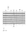
- FIG. 3 is a plan view showing a detection image.
- FIG. 4 is a diagram for explaining the epipolar line.
- 5 and 6 are diagrams for explaining touch recognition.
- FIG. 7 is a diagram for explaining an example of a method for calculating the separation distance between the screen and the finger.
- three axes orthogonal to each other are defined as an X axis, a Y axis, and a Z axis, and the Y axis is along the vertical direction.
- the image recognition unit 100 shown in FIG. 1 is a device that can determine whether or not a finger F as an object is in contact with a flat screen 900 as an image display surface. According to such an image recognition unit 100, an image displayed on the screen 900 by detecting the contact of the finger F with the screen 900 (an image that an observer wants to visually recognize. Hereinafter also referred to as a “display image”). ) Can be switched.
- touch recognition the determination of whether or not the finger F is in contact with the screen 900 is referred to as “touch recognition”.
- the image recognition unit 100 can be used for presentation, for example, and performs touch recognition of the presenter's finger F to switch, enlarge or reduce the display image displayed on the screen 900 when necessary. Thus, the presentation can proceed smoothly.
- the image display surface is not limited to the screen 900, and may be, for example, a wall or glass.
- the image display surface may not be flat, and may be a spherical surface or an uneven surface. Further, the shape of the image display surface may change over time.
- the object to be touch-recognized is not limited to the finger F, and may be, for example, a pointing stick or a magnet attracted to the image display surface.
- the use of the image recognition unit 100 is not limited to the presentation, and for example, it can be used for various uses such as store guidance for department stores and the like, introduction / search for handled products, and the like.
- such an image recognition unit 100 includes a projector 300 as a detection image display device that displays a detection image 800 on a screen 900, and a camera as an imaging device that images the screen 900. 400, an image recognition device 500 that performs touch recognition, and a projector 700 as an image display device that displays a display image (image) on a screen 900.
- the projector 300 and the camera 400 are arranged at different positions. Further, the relative (geometric) positional relationship between the projector 300 and the camera 400 is constant, and information on the positional relationship is stored in a storage unit (not shown) included in the image recognition device 500 and used as appropriate.
- a surface including a light beam group that forms an end on the upper side in the vertical direction (+ Y axis side) of the detection image 800 is a first virtual plane f1, and a lower side in the vertical direction ( ⁇ Y axis) of the detection image 800.
- the surface including the light beam group forming the edge of the second side is located between the second virtual surface f2, the screen 900 and the projector 300, and the region sandwiched between the first virtual surface f1 and the second virtual surface f2 is the first.
- the camera is placed in the second quadrant S2.
- 400 is arranged.
- the projector 300 is suspended from a ceiling or the like, for example, and is disposed so as to emit light from a relatively high position toward a diagonally lower side. Then, light having an optical axis that coincides with the normal line (Z axis) of the screen 900 is not emitted from the projector 300, and both the first virtual surface f1 and the second virtual surface f2 are on the screen 900 side from the projector 300 side.
- the projector 300 and the camera 400 are arranged side by side along the normal direction (Z-axis direction) of the screen 900 when viewed from above in the vertical direction. Furthermore, the optical axis of the projector 300 and the optical axis of the camera 400 are each along the normal direction.
- the arrangement of the projector 300 and the camera 400 has been described above, the arrangement of the projector 300 and the camera 400 is not limited to the above arrangement as long as the camera 400 is arranged in the second quadrant S2.
- the projector 300 is a device that displays a detection image 800 for performing touch recognition on a screen 900.
- the projector 300 according to the present embodiment includes a light source that emits NIR (near infrared) light, a diffractive optical element that diffracts NIR light emitted from the light source, and a lens system that projects the diffracted NIR light. It has become.
- the configuration of the projector 300 becomes relatively simple.
- the use of NIR light makes it difficult for humans to visually recognize the detection image 800, so there is no possibility of degrading the video (display image) from the projector 700.
- the projector 300 is not limited to the configuration of the present embodiment as long as the detection image 800 can be projected onto the screen 900.
- the projector 300 may be an optical scanning projector or an LCD projector. Alternatively, it may be a DMD projector.
- the light source of the projector 300 is not limited to a light source that emits NIR light, and may be a light source that emits visible light.
- the detection image 800 is provided with a luminance change that is difficult to be visually recognized by humans, or is periodically displayed at a frequency that is difficult to be visually recognized by human eyes. Thereby, the possibility that the display image is deteriorated due to the overlap with the detection image 800 can be reduced.
- a linear pattern 810 extending in a direction intersecting with the epipolar line EL is along the extending direction of the epipolar line EL.
- the images are arranged at equal pitches (equal intervals).
- the detection image 800 has a relatively simple configuration.
- the linear pattern 810 is orthogonal to the epipolar line EL. Therefore, the minimum pitch can be increased as compared with the linear pattern 810 that has the same pitch in the extending direction of the epipolar line EL but is not orthogonal to the epipolar line EL. Therefore, the adjacent linear pattern 810 can be more clearly discriminated by the image recognition apparatus 500, and touch recognition can be performed with higher accuracy.
- the pitch of the linear pattern 810 is not particularly limited, and may vary depending on the resolution of the camera 400, for example, about 5 mm or more and 20 mm or less.
- FIG. 3 illustrates a detection image 800 that is stereo-parallelized so that the epipolar line EL has a vertical component for convenience of explanation.
- the linear pattern 810 is an arc-shaped pattern.
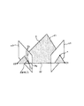
- the epipolar line EL is a line determined by the geometric (relative) positional relationship between the projector 300 and the camera 400. Specifically, as shown in FIG. 4, a straight line (baseline) 12 connecting the camera center (lens system principal point) C1 of the camera 400 and the projector center (lens system principal point) C2 of the projector 300; An intersection of the projector 300 with the virtual image plane ⁇ 2 is referred to as an epipolar point Pe, and all straight lines passing through the epipolar point Pe in the virtual image plane ⁇ 2 are referred to as epipolar lines EL.
- the coordinate (in-plane coordinate) x of the finger F in the image plane ⁇ 1 of the camera 400 is determined.
- a plane defined by a straight line l1 and a straight line l2 passing through the coordinate x and the camera center C1 is referred to as an epipolar plane ⁇ .
- the epipolar line EL coincident with the straight line 13 formed by the intersection of the epipolar plane ⁇ and the virtual image plane ⁇ 2 is defined as “epipolar line EL ′”
- the finger F is located somewhere on the epipolar line EL ′. become.
- the detection image 800 is not limited to this as long as it can be used for touch recognition.
- the detection image 800 is an image in which a plurality of dots (dots) are uniformly scattered. There may be.
- the camera 400 is a device that captures a detection image 800 on the screen 900.
- a camera 400 is, for example, an NIR camera corresponding to NIR light, and includes a light receiving unit including a lens system and an image sensor, and a processing unit that processes a video signal from the image sensor.
- the image recognition apparatus 500 is an apparatus that performs touch recognition using the projector 300 and the camera 400 described above.
- Such an image recognition apparatus 500 includes an image processing unit 510 as shown in FIG.
- the image processing unit 510 uses the light from the projector 300 (light for forming the detection image 800) when the finger F is positioned between the projector 300 and the screen 900.
- a distance D between the detection image 800 and the detection image 800 is detected, and touch recognition is performed based on a detection result (the obtained distance D).
- the image processing unit 510 will be specifically described.
- FIG. 5 and 6 are diagrams showing images obtained by stereo-parallelizing the detection image 800 on the screen 900 captured by the camera 400, respectively.
- the finger F is not present between the screen 900 and the projector 300, the light from the projector 300 is irradiated on the screen 900 without being blocked, so that the detection displayed on the screen 900 as shown in FIG.
- the disappearance 890 does not occur in the work image 800.
- the finger F exists between the screen 900 and the projector 300, the light from the projector 300 is blocked by the finger F, so that the detection displayed on the screen 900 as shown in FIG.
- the disappearance portion 890 corresponding to the portion obstructed by the finger F is generated in the image 800, and the portion disappeared by the disappearance portion 890 (disappearance portion) is displayed on the finger F while being shifted in the extending direction of the epipolar line EL. ing.
- the image processing unit 510 obtains a distance D along the epipolar line EL 'between the position P1 and the position P2. Since the distance D becomes smaller as the distance between the screen 900 and the finger F is shorter, the image processing unit 510 makes the finger F touch the screen 900 if the distance D is equal to or smaller than a preset threshold value, for example. If it exceeds the threshold, it is determined that the finger F is not in contact with the screen 900 (determination step). According to such an image processing unit 510, since it is only necessary to obtain the distance D, it is possible to perform touch recognition relatively easily and with high accuracy.
- the image processing unit 510 detects the XY coordinates (plane coordinates) of the touch position of the finger F from the stereo-parallelized image. Note that since the tip of the disappearing portion 890 corresponds to the position of the tip of the finger F, it is preferable to detect the coordinates of the tip of the disappearing portion 890 (the disappearing portion 811a) as the coordinates of the touch position.
- the image processing unit 510 transmits the result of touch recognition to a control unit (not shown).
- the control unit that has received the determination result sends the determination result to the projector 700 based on the coordinate information of the touch position transmitted together.
- a screen operation command determined by the contact position of the finger F such as a command for enlarging or reducing the display image displayed on the screen 900 and a command for switching the display image is transmitted.
- the focal length of the camera 400 is f
- the base line length consisting of the distance between the camera 400 and the projector 300 is L
- the inclination of the optical axis of the camera 400 with respect to the screen 900 is ⁇
- the distance between the camera 400 and the screen 900 (stereo reference plane) is h
- tan ⁇ 1 z1 / (L ⁇ y1)
- z2 y2 ⁇ (f /
- the relationship of i2) is satisfied.
- FIG. 8 is a diagram for explaining touch recognition of the image recognition unit according to the second embodiment of the present invention.
- FIG. 8 for convenience of explanation, a diagram in which the epipolar lines are stereo-parallelized so as to have a vertical component is shown.
- the image recognition unit of the second embodiment is the same as that of the first embodiment described above except that the configuration of the image recognition apparatus is different.
- symbol is attached
- the image processing unit 510 of the present embodiment can detect the XY coordinates of the touch position more accurately than the first embodiment described above. This will be specifically described below.
- the image processing unit 510 according to the present embodiment includes a position estimation unit that estimates the position of the tip of the finger F based on the shape of the disappearance unit 890. As shown in FIG. 8, the position estimation unit sets line segments Lf that pass through the midpoints P 811 and P 812 in the length direction of the disappearance portions 811a and 812a of the linear patterns 811 and 812 that disappear at the disappearance portion 890. It is estimated that the finger F extends in the extending direction of the line segment Lf.
- an equilateral triangular marker M having one side having the same length as the disappearance portion 811a located on the uppermost side of the disappearance portion 890 of the disappearance portions 811a and 812a is virtually generated, and this marker M is disappeared. It arrange
- the pitch of the linear pattern 810 and D 810, when the length of the lost portion 811a (disappearance portion most located above the lost portion 890) has a D 890, when satisfying the relationship of D 810> D 890 Only the above-described estimation by the position estimation unit is preferably performed. In other words, it is preferable to perform the above-described estimation by the position estimation unit only when the vertex Pm of the marker M is positioned below the linear pattern 810 positioned immediately above the linear pattern 811. This is because, when D 810 ⁇ D 890 , if the above estimation by the position estimation unit is performed, the amount of deviation from the actual position of the tip of the finger F may be larger than when estimation is not performed. Because there is.
- the marker M is an equilateral triangle, but the shape of the marker M is not particularly limited, and can be appropriately changed so as to follow the tip shape of the object.
- FIG. 9 is a diagram showing a detection image used in the image recognition unit according to the third embodiment of the present invention.
- 10 and 11 are diagrams in which images acquired by the camera are stereo-parallelized.
- the image recognition unit of the third embodiment is the same as that of the first embodiment described above except that the detection images are different.
- symbol is attached
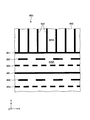
- the detection image 800 of the present embodiment extends so as to intersect with the epipolar line EL (orthogonal in the present embodiment), and the first linear pattern 820 and the second linear pattern having different patterns from each other. It has a pattern 830, and first and second linear patterns 820 and 830 are alternately arranged along the extending direction of the epipolar line EL.
- the first linear pattern 820 has a constant luminance in the extending direction
- the second linear pattern 830 includes a portion having a first luminance and a portion having a second luminance different from the first luminance. Are alternately and periodically (equally spaced).
- the first and second linear patterns 820 Since the angle with the camera 400 becomes smaller at the lower side of the screen 900, in the image acquired by the camera 400, as shown in FIG. 10, the first and second linear patterns 820, As the pitch of 830 gradually decreases, the widths of the first and second linear patterns 820 and 830 also gradually decrease. Therefore, depending on the resolution (resolution) of the camera 400, the detection image 800 (first and second linear patterns 820 and 830) shown on the upper portion of the screen 900 can be clearly recognized, but the screen 900 It may be difficult to clearly recognize the detection image 800 (first and second linear patterns 820 and 830) shown in the lower part.
- the first and second linear patterns 820 and 830 is located on the uppermost side (tip side) of the disappearing portion 890 at the lower part of the screen 900.
- the angle with the camera 400 becomes large, so the first and second linear patterns 820 and 830 appearing on the finger F.
- the first and the most distant portion 890 are located on the most distal side. It can be determined which of the second linear patterns 820 and 830 is.
- touch recognition can be performed with a resolution higher than that of the camera 400, and the XY coordinates of the touch position can be acquired.
- the detection image has a configuration in which the first linear pattern 820 and the second linear pattern 830 are alternately arranged along the extending direction of the epipolar line EL.
- the image for use is not particularly limited. For example, you may have the 3rd linear pattern different from the 1st, 2nd linear pattern 820,830.
- FIG. 12 is a diagram showing a detection image used in the image recognition unit according to the fourth embodiment of the present invention.
- FIG. 13 is a diagram showing a modification of the detection image shown in FIG.
- the image recognition unit of the fourth embodiment is the same as that of the first embodiment described above except that the detection images are different.
- symbol is attached
- the detection image 800 is such that accurate touch recognition can be performed even when the finger F approaches the screen 900 along the normal direction of the screen 900.
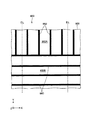
- the detection image 800 of the present embodiment is positioned in the first area 800A located on the upper part of the screen 900 (on the side closer to the camera 400) and on the lower part of the screen 900 (on the side far from the camera 400).
- a second region 800B In the first region 800A, a plurality of linear patterns 850 extending along the epipolar line EL are arranged at an equal pitch along the direction orthogonal to the epipolar line EL.
- a plurality of linear patterns 860 intersecting with the epipolar line EL (or orthogonal in the present embodiment) are arranged at an equal pitch along the extending direction of the epipolar line EL.
- a detection image 800 as shown in FIG. 13 may be used.
- a plurality are arranged in a pitch and alternately. According to such a configuration, touch recognition can be performed with high accuracy even in the lower portion of the screen 900, as in the third embodiment described above.
- FIG. 14 is a side view showing the configuration of the image recognition unit according to the fifth embodiment of the present invention.
- the image recognition unit of the fifth embodiment is the same as that of the first embodiment described above except that the arrangement of the image sensor and the image display device for detection is different.
- symbol is attached
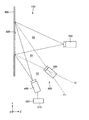
- the camera 400 is arranged in the third quadrant S3.
- the projector 300 is installed on the floor, for example, and is arranged so as to emit light obliquely upward from a relatively low position. Then, light having an optical axis that coincides with the normal line of the screen 900 is not emitted from the projector 300, and both the first virtual surface f1 and the second virtual surface f2 are positioned above the projector 300 side. Inclined to do.
- this embodiment is the structure which turned the structure of 1st Embodiment mentioned above upside down, and will be description of this embodiment if the description of 1st Embodiment is turned upside down. Therefore, detailed description of this embodiment is omitted.
- FIG. 15 is a side view showing the configuration of the image recognition unit according to the sixth embodiment of the present invention.
- the image recognition unit of the sixth embodiment is the same as that of the first embodiment described above except that the arrangement of the image display device for detection is different.
- symbol is attached
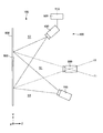
- the present embodiment light having an optical axis that coincides with the normal line of the screen 900 is emitted from the projector 300, and the first virtual plane f1 is positioned on the screen 900 side above the projector 300 side.
- the second virtual plane f2 is inclined so that the screen 900 side is positioned below the projector 300 side.
- the configuration of each unit can be replaced with an arbitrary configuration having the same function, and another arbitrary configuration can be added.
- the Y axis is arranged along the vertical direction, but the Y axis may not be along the vertical direction. That is, with respect to the above-described embodiment, the Y axis may be rotated by a predetermined angle around the X axis, or the Y axis may be rotated by a predetermined angle around the Z axis.
- epipolar line F ... finger, Lf ... line segment, l1 , l2, l3 ... straight line, M ... marker, P1, P2 ... position, P 811, P 812 ... the midpoint, Pe ... epipolar point, Pm Vertex, S1 ... first quadrant, S2 ... second quadrant, S3 ... third quadrant, f1 ... first virtual plane, f2 ... second virtual plane, x ... coordinate, ⁇ ... epipolar plane, ⁇ 1 ... image plane, ⁇ 2 ... Virtual image plane
Abstract
精度の高いタッチ認識を行うことのできる画像認識装置、画像認識方法および画像認識ユニットを提供する。 第2象限または第3象限に撮像装置が配置され、前記撮像装置が取得した画像に基づいて、検出用画像表示装置と画像表示面との間に対象物が位置したときに前記対象物によって前記検出用画像表示装置からの光が遮られることで前記画像表示面上に生じる消失部と、前記撮像装置と前記検出用画像表示装置の位置関係から決定され、かつ、前記消失部を通るエピポーラ線上にあって、前記対象物上に表示される前記検出用画像と、の距離に基づいてタッチ認識を行う画像処理部を有することを特徴とする画像認識装置。
Description
本発明は、画像認識装置、画像認識方法および画像認識ユニットに関するものである。
プロジェクターからの画像が投影されたスクリーンに指が触れているかいないかを検知する画像認識に応用できると思われる技術として、NIR光ランダムスペックルパターンを投影し、指で反射したNIR光(反射光)をNIRカメラで取得し、取得した情報からスクリーンに指が触れているかいないかを検知する技術がある(例えば、特許文献1参照)。
しかしながら、特許文献1に記載の画像認識技術では、NIRカメラから見たときの指の奥行き方向の位置(深度)の検知精度が悪く、それに伴って、タッチ認識の精度も悪いという問題がある。
本発明の目的は、精度の高いタッチ認識を行うことのできる画像認識装置、画像認識方法および画像認識ユニットを提供することにある。
このような目的は、下記の本発明により達成される。
本発明の画像認識装置は、画像表示面に検出用画像を表示する検出用画像表示装置と、前記画像表示面を撮像する撮像装置と、を有し、前記検出用画像の鉛直方向上側の端を形成する光線群を含む面を第1仮想面、前記検出用画像の鉛直方向下側の端を形成する光線群を含む面を第2仮想面、前記画像表示面と前記検出用画像表示装置との間に位置し、前記第1仮想面と前記第2仮想面とに挟まれた領域を第1象限、前記第1象限の鉛直方向上側に位置する領域を第2象限、前記第1象限の鉛直方向下側に位置する領域を第3象限としたとき、前記第2象限または前記第3象限に前記撮像装置が配置されている画像表示ユニットで用いられる画像認識装置であって、
前記撮像装置が取得した画像に基づいて、前記検出用画像表示装置と前記画像表示面との間に対象物が位置したときに前記対象物によって前記検出用画像表示装置からの光が遮られることで前記画像表示面上に生じる消失部と、前記撮像装置と前記検出用画像表示装置の位置関係から決定され、かつ、前記消失部を通るエピポーラ線上にあって、前記対象物上に表示される前記検出用画像と、の距離を検知し、検知結果に基づいて前記対象物が前記画像表示面に接触しているか否かを判断する画像処理部を有することを特徴とする。
これにより、精度の高いタッチ認識を行うことのできる画像認識装置となる。
前記撮像装置が取得した画像に基づいて、前記検出用画像表示装置と前記画像表示面との間に対象物が位置したときに前記対象物によって前記検出用画像表示装置からの光が遮られることで前記画像表示面上に生じる消失部と、前記撮像装置と前記検出用画像表示装置の位置関係から決定され、かつ、前記消失部を通るエピポーラ線上にあって、前記対象物上に表示される前記検出用画像と、の距離を検知し、検知結果に基づいて前記対象物が前記画像表示面に接触しているか否かを判断する画像処理部を有することを特徴とする。
これにより、精度の高いタッチ認識を行うことのできる画像認識装置となる。
本発明の画像認識装置では、前記検出用画像は、前記エピポーラ線に交差する線状パターンを有していることが好ましい。
これにより、検出用画像が比較的簡単な構成となる。
これにより、検出用画像が比較的簡単な構成となる。
本発明の画像認識装置では、前記撮像装置は、前記第2象限に配置され、
前記第1仮想面および前記第2仮想面は、共に、前記画像表示面側が前記検出用画像表示装置側よりも下方に位置するように傾斜していることが好ましい。
これにより、消失部を撮像装置でより確実に撮像することができる。
前記第1仮想面および前記第2仮想面は、共に、前記画像表示面側が前記検出用画像表示装置側よりも下方に位置するように傾斜していることが好ましい。
これにより、消失部を撮像装置でより確実に撮像することができる。
本発明の画像認識装置では、前記撮像装置は、前記第3象限に配置され、
前記第1仮想面および前記第2仮想面は、共に、前記画像表示面側が前記検出用画像表示装置側よりも上方に位置するように傾斜していることが好ましい。
これにより、消失部を撮像装置でより確実に撮像することができる。
前記第1仮想面および前記第2仮想面は、共に、前記画像表示面側が前記検出用画像表示装置側よりも上方に位置するように傾斜していることが好ましい。
これにより、消失部を撮像装置でより確実に撮像することができる。
本発明の画像認識装置では、前記線状パターンの前記消失部によって消失した消失部分は、前記対象物上に表示され、
前記画像処理部は、前記消失部分の前記対象物が無い場合に表示されている位置と、前記対象物上に表示されている実際の位置と、の前記エピポーラ線に沿った距離を検出することが好ましい。
これにより、比較的簡単に、かつ、高精度にタッチ認識を行うことができる。
前記画像処理部は、前記消失部分の前記対象物が無い場合に表示されている位置と、前記対象物上に表示されている実際の位置と、の前記エピポーラ線に沿った距離を検出することが好ましい。
これにより、比較的簡単に、かつ、高精度にタッチ認識を行うことができる。
本発明の画像認識装置では、前記画像処理部は、前記消失部の形状に基づいて、前記対象物の先端部の位置を推定する位置推定部を有していることが好ましい。
これにより、対象物と画像表示面との接触位置をより正確に検出することができる。
これにより、対象物と画像表示面との接触位置をより正確に検出することができる。
本発明の画像認識装置では、前記検出用画像は、前記エピポーラ線に交差して延在し、互いにパターンが異なる第1線状パターンおよび第2線状パターンを有し、
前記第1線状パターンおよび前記第2線状パターンが前記エピポーラ線の延在方向に沿って交互に並んで配置されていることが好ましい。
これにより、撮像装置の分解能よりも高い分解能で、タッチ認識を行うことができると共に、対象物と画像表示面との接触位置を検出することができる。
前記第1線状パターンおよび前記第2線状パターンが前記エピポーラ線の延在方向に沿って交互に並んで配置されていることが好ましい。
これにより、撮像装置の分解能よりも高い分解能で、タッチ認識を行うことができると共に、対象物と画像表示面との接触位置を検出することができる。
本発明の画像認識装置では、前記検出用画像は、前記撮像装置から近い側に位置する第1領域と、前記第1領域よりも前記撮像装置から遠い側に位置する第2領域と、を有し、 前記第1領域には前記エピポーラ線に沿って延在する線状パターンが配置され、前記第2領域には前記エピポーラ線に交差する線状パターンが配置されていることが好ましい。
これにより、特に、第1領域において、より確実に、タッチ認識を行うことができる。
これにより、特に、第1領域において、より確実に、タッチ認識を行うことができる。
本発明の画像認識方法は、画像表示面に検出用画像を表示する検出用画像表示装置と、前記画像表示面を撮像する撮像装置と、を有し、前記検出用画像の鉛直方向上側の端を形成する光線群を含む面を第1仮想面、前記検出用画像の鉛直方向下側の端を形成する光線群を含む面を第2仮想面、前記画像表示面と前記検出用画像表示装置との間に位置し、前記第1仮想面と前記第2仮想面とに挟まれた領域を第1象限、前記第1象限の鉛直方向上側に位置する領域を第2象限、前記第1象限の鉛直方向下側に位置する領域を第3象限としたとき、前記第2象限または前記第3象限に前記撮像装置が配置されている画像表示ユニットで用いられる画像認識方法であって、
前記撮像装置が取得した画像に基づいて、前記検出用画像表示装置と前記画像表示面との間に対象物が位置したときに前記対象物によって前記検出用画像表示装置からの光が遮られることで前記画像表示面上に生じる消失部と、前記撮像装置と前記検出用画像表示装置の位置関係から決定され、かつ、前記消失部を通るエピポーラ線上にあって、前記対象物上に表示される前記検出用画像と、の距離を検知し、検知結果に基づいて前記対象物が前記画像表示面に接触しているか否かを判断する判断ステップを有することを特徴とする。
これにより、精度の高いタッチ認識を行うことができる。
前記撮像装置が取得した画像に基づいて、前記検出用画像表示装置と前記画像表示面との間に対象物が位置したときに前記対象物によって前記検出用画像表示装置からの光が遮られることで前記画像表示面上に生じる消失部と、前記撮像装置と前記検出用画像表示装置の位置関係から決定され、かつ、前記消失部を通るエピポーラ線上にあって、前記対象物上に表示される前記検出用画像と、の距離を検知し、検知結果に基づいて前記対象物が前記画像表示面に接触しているか否かを判断する判断ステップを有することを特徴とする。
これにより、精度の高いタッチ認識を行うことができる。
本発明の画像認識ユニットは、本発明の画像認識装置と、
前記検出用画像表示装置と、
前記撮像装置と、を有することを特徴とする。
これにより、精度の高いタッチ認識を行うことのできる画像認識ユニットが得られる。
前記検出用画像表示装置と、
前記撮像装置と、を有することを特徴とする。
これにより、精度の高いタッチ認識を行うことのできる画像認識ユニットが得られる。
本発明の画像認識ユニットでは、前記画像表示面に画像を表示する画像表示装置を有することが好ましい。
これにより、画像表示面に所望の画像を表示することができる。
これにより、画像表示面に所望の画像を表示することができる。
以下、本発明の画像認識装置、画像認識方法および画像認識ユニットの好適な実施形態について、添付図面を参照しつつ説明する。
<第1実施形態>
図1は、本発明の第1実施形態に係る画像認識ユニットの構成を示す側面図である。図2は、図1に示す画像認識ユニットの上面図である。図3は、検出用画像を示す平面図である。図4は、エピポーラ線について説明する図である。図5および図6は、タッチ認識を説明するための図である。図7は、スクリーンと指の離間距離の算出方法の一例を説明するための図である。なお、説明の便宜上、図1に示すように、互いに直交する3軸をX軸、Y軸およびZ軸とし、Y軸が鉛直方向に沿うこととする。
図1は、本発明の第1実施形態に係る画像認識ユニットの構成を示す側面図である。図2は、図1に示す画像認識ユニットの上面図である。図3は、検出用画像を示す平面図である。図4は、エピポーラ線について説明する図である。図5および図6は、タッチ認識を説明するための図である。図7は、スクリーンと指の離間距離の算出方法の一例を説明するための図である。なお、説明の便宜上、図1に示すように、互いに直交する3軸をX軸、Y軸およびZ軸とし、Y軸が鉛直方向に沿うこととする。
図1に示す画像認識ユニット100は、画像表示面としての平坦なスクリーン900に対象物としての指Fが接触しているか否かを判断することのできる装置である。このような画像認識ユニット100によれば、スクリーン900への指Fの接触を検知することでスクリーン900に映し出されている画像(観察者に視認させたい画像。以下「表示用画像」とも言う。)を切り替えることができる。なお、以下では、説明の便宜上、スクリーン900に指Fが接触しているか否かの判断を「タッチ認識」と言う。
また、画像認識ユニット100は、例えば、プレゼンテーションに利用することができ、プレゼンターの指Fのタッチ認識を行って、必要時にスクリーン900に映し出される表示用画像を切り替えたり、拡大または縮小したりすることで、プレゼンテーションをスムーズに進行することが可能となる。
なお、画像表示面としては、スクリーン900に限定されず、例えば、壁、ガラス等であってもよい。また、画像表示面は、平坦でなくてもよく、球面や凹凸面であってもよい。また、画像表示面は、経時的に形状が変化してもよい。また、タッチ認識を行う対象物としては、指Fに限定されず、例えば、指し棒、画像表示面に吸着したマグネット等であってもよい。また、画像認識ユニット100の用途としては、プレゼンテーションに限定されず、例えば、デパート等の店舗案内、取扱商品の紹介・検索等、様々な用途に用いることができる。
このような画像認識ユニット100は、図1および図2に示すように、スクリーン900に検出用画像800を表示する検出用画像表示装置としてのプロジェクター300と、スクリーン900を撮像する撮像装置としてのカメラ400と、を有する画像表示ユニット200と、タッチ認識を行う画像認識装置500と、スクリーン900に表示用画像(画像)を表示する画像表示装置としてのプロジェクター700と、を有している。
プロジェクター300およびカメラ400は、異なる位置に配置されている。また、プロジェクター300およびカメラ400の相対的(幾何的)な位置関係は一定であり、位置関係に関する情報は、画像認識装置500が有する図示しない記憶部に記憶され、適宜使用される。
ここで、プロジェクター300およびカメラ400の具体的な位置関係を説明する。図1に示すように、検出用画像800の鉛直方向上側(+Y軸側)の端を形成する光線群を含む面を第1仮想面f1、検出用画像800の鉛直方向下側(-Y軸側)の端を形成する光線群を含む面を第2仮想面f2、スクリーン900とプロジェクター300との間に位置し、第1仮想面f1と第2仮想面f2とに挟まれた領域を第1象限S1、第1象限S1の鉛直方向上側に位置する領域を第2象限S2、第1象限S1の鉛直方向下側に位置する領域を第3象限S3としたとき、第2象限S2にカメラ400が配置されている。また、プロジェクター300は、例えば、天井等に吊り下げられており、比較的高い位置から斜め下側に向けて光を出射するように配置されている。そして、プロジェクター300からはスクリーン900の法線(Z軸)と一致する光軸を持つ光が出射されず、第1仮想面f1および第2仮想面f2が、共に、スクリーン900側がプロジェクター300側よりも下方に位置するように傾斜している。プロジェクター300およびカメラ400をこのような配置とすることで、プロジェクター300とスクリーン900との間に指Fが存在したときに、指Fによってプロジェクター300からの光(検出用画像800を形成する光)が遮蔽されることでスクリーン900上に生じる消失部890(影部。図6参照。)をカメラ400でより確実に撮像することができる。
また、図2に示すように、鉛直方向上側から見た平面視で、プロジェクター300とカメラ400とは、スクリーン900の法線方向(Z軸方向)に沿って並んで配置されている。さらには、プロジェクター300の光軸およびカメラ400の光軸が、それぞれ、法線方向に沿っている。
以上、プロジェクター300およびカメラ400の配置について説明したが、プロジェクター300およびカメラ400の配置としては、第2象限S2にカメラ400が配置されていれば、上述の配置に限定されない。
以下、プロジェクター300、カメラ400および画像認識装置500について順に説明する。
[プロジェクター300]
プロジェクター300は、タッチ認識を行うための検出用画像800をスクリーン900に表示する装置である。本実施形態のプロジェクター300は、NIR(近赤外)光を出射する光源と、光源から出射されたNIR光を回折する回折光学素子と、回折したNIR光を投影するレンズ系と、を有する構成となっている。これにより、プロジェクター300の構成が比較的簡単なものとなる。特に、NIR光を用いることで、検出用画像800が人間に視認され難くなるため、プロジェクター700からの映像(表示用画像)を劣化させるおそれがない。
プロジェクター300は、タッチ認識を行うための検出用画像800をスクリーン900に表示する装置である。本実施形態のプロジェクター300は、NIR(近赤外)光を出射する光源と、光源から出射されたNIR光を回折する回折光学素子と、回折したNIR光を投影するレンズ系と、を有する構成となっている。これにより、プロジェクター300の構成が比較的簡単なものとなる。特に、NIR光を用いることで、検出用画像800が人間に視認され難くなるため、プロジェクター700からの映像(表示用画像)を劣化させるおそれがない。
なお、プロジェクター300としては、検出用画像800をスクリーン900に投影することができれば本実施形態の構成に限定されず、例えば、光走査方式のプロジェクターであってもよいし、LCD方式のプロジェクターであってもよいし、DMD方式のプロジェクターであってもよい。また、プロジェクター300の光源としては、NIR光を出射する光源に限定されず、可視光を出射する光源であってもよい。この場合には、検出用画像800を人間に視認され難いような輝度変化を与えたものとしたり、人間の眼で視認され難い周波数で周期的に表示したりするようにすることが好ましい。これにより、検出用画像800との重なりによって表示用画像が劣化するおそれを低減することができる。
このようなプロジェクター300によってスクリーン900に表示される検出用画像800は、図3に示すように、エピポーラ線ELに対して交差する方向に延びる線状パターン810がエピポーラ線ELの延在方向に沿って等ピッチ(等間隔)に複数配置された画像となっている。これにより、検出用画像800が比較的簡単な構成となる。特に、本実施形態では、線状パターン810がエピポーラ線ELに対して直交している。そのため、エピポーラ線ELの延在方向でのピッチは同じであるがエピポーラ線ELに対して直交していない線状パターン810と比較して、最小ピッチを大きくすることができる。したがって、画像認識装置500によって、隣り合う線状パターン810をより明確に判別することができ、タッチ認識をより高精度に行うことができる。ここで、線状パターン810のピッチとしては特に限定されず、カメラ400の分解能によっても異なるが、例えば、5mm以上、20mm以下程度とすることができる。なお、図3は、説明の便宜上、エピポーラ線ELが垂直成分となるようにステレオ平行化した検出用画像800を図示している。実際には、エピポーラ線ELが放射状に延びていることから、線状パターン810は、円弧状のパターンとなる。
ここで、エピポーラ線ELについて簡単に説明する。エピポーラ線ELは、プロジェクター300とカメラ400の幾何的(相対的)な位置関係によって決定する線である。具体的には、図4に示すように、カメラ400のカメラ中心(レンズ系の主点)C1とプロジェクター300のプロジェクター中心(レンズ系の主点)C2とを結ぶ直線(ベースライン)l2と、プロジェクター300の仮想画像平面π2との交点をエピポーラ点Peと言い、仮想画像平面π2内においてエピポーラ点Peを通る全ての直線をエピポーラ線ELと言う。
また、指Fがカメラ400の画像に含まれていれば、カメラ400の画像平面π1内での指Fの座標(面内座標)xが決定される。この座標xとカメラ中心C1とを通る直線l1と直線l2とによって規定される平面をエピポーラ平面Σと言う。そして、エピポーラ平面Σと仮想画像平面π2とが交差してできる直線l3と一致するエピポーラ線ELを「エピポーラ線EL’」とした場合、エピポーラ線EL’上のどこかに指Fが位置することになる。
以上、検出用画像800について説明したが、検出用画像800としては、タッチ認識に用いることができれば、これに限定されず、例えば、複数の点(ドット)が均一に散らばっているような画像であってもよい。
[カメラ400]
カメラ400は、スクリーン900上の検出用画像800を撮像する装置である。このようなカメラ400は、例えば、NIR光に対応したNIRカメラであり、レンズ系および撮像素子を備える受光ユニットと、撮像素子からの映像信号を処理する処理部と、を有している。
カメラ400は、スクリーン900上の検出用画像800を撮像する装置である。このようなカメラ400は、例えば、NIR光に対応したNIRカメラであり、レンズ系および撮像素子を備える受光ユニットと、撮像素子からの映像信号を処理する処理部と、を有している。
[画像認識装置]
画像認識装置500は、前述したプロジェクター300およびカメラ400を用いてタッチ認識を行う装置である。このような画像認識装置500は、図1に示すように、画像処理部510を有している。画像処理部510は、カメラ400が取得した画像に基づいて、プロジェクター300とスクリーン900との間に指Fが位置したときに当該指Fによってプロジェクター300からの光(検出用画像800を形成する光)が遮られることでスクリーン900上に生じる消失部890と、カメラ400とプロジェクター300の位置関係から決定され、かつ、消失部890を通るエピポーラ線EL’上にあって指F上に表示される検出用画像800と、の距離Dを検知し、検知結果(求められた距離D)に基づいてタッチ認識を行うように構成されている。このように、距離Dに基づくことで、簡単かつ高精度なタッチ認識が可能となる。以下、画像処理部510について具体的に説明する。
画像認識装置500は、前述したプロジェクター300およびカメラ400を用いてタッチ認識を行う装置である。このような画像認識装置500は、図1に示すように、画像処理部510を有している。画像処理部510は、カメラ400が取得した画像に基づいて、プロジェクター300とスクリーン900との間に指Fが位置したときに当該指Fによってプロジェクター300からの光(検出用画像800を形成する光)が遮られることでスクリーン900上に生じる消失部890と、カメラ400とプロジェクター300の位置関係から決定され、かつ、消失部890を通るエピポーラ線EL’上にあって指F上に表示される検出用画像800と、の距離Dを検知し、検知結果(求められた距離D)に基づいてタッチ認識を行うように構成されている。このように、距離Dに基づくことで、簡単かつ高精度なタッチ認識が可能となる。以下、画像処理部510について具体的に説明する。
図5および図6は、それぞれ、カメラ400で撮像したスクリーン900上の検出用画像800をステレオ平行化した画像を示す図である。スクリーン900とプロジェクター300との間に指Fが存在しない場合には、プロジェクター300からの光が遮られることなくスクリーン900に照射されるため、図5に示すように、スクリーン900に表示された検出用画像800には消失部890が生じない。これに対して、スクリーン900とプロジェクター300との間に指Fが存在する場合には、プロジェクター300からの光が指Fに遮られるため、図6に示すように、スクリーン900に表示された検出用画像800には指Fで遮られた部分に相当する消失部890が生じ、消失部890によって消失した部分(消失部分)は、エピポーラ線ELの延在方向にずれて指F上に表示されている。
図6に示すように、線状パターン811、812(810)の消失部890によって消失した消失部分811a、812aは、エピポーラ線EL’の延在方向にずれて指F上に表示される。そのため、画像処理部510は、ステレオ平行化した画像から、消失部890と重なる線状パターン811、812のうち最も上側(指Fに対して遠位側)に位置する線状パターン811の位置に基づいて、消失部分811aの本来の位置P1(指Fが無い場合に表示されている位置)を設定し、次に、位置P1を通るエピポーラ線EL’上に位置し、指F上に表示されている実際の消失部分811aの位置P2を設定する。なお、指F上の消失部分811aと消失部890との間に線状パターン811以外の線状パターン810が表示されることはあり得ず、消失部890を下側に抜けて最初に出現する線状パターン810が消失部分811aであると断定することができる。そして、次に、画像処理部510は、位置P1と位置P2とのエピポーラ線EL’に沿った距離Dを求める。この距離Dは、スクリーン900と指Fとの離間距離が短い程、小さくなるため、画像処理部510は、例えば、距離Dが予め設定した閾値以下であれば、指Fがスクリーン900に接触している「接触状態」と判断し、閾値を超えていれば、指Fがスクリーン900に接触していない「非接触状態」と判断する(判断ステップ)。このような画像処理部510によれば、距離Dを求めるだけでよいため、比較的簡単に、かつ、高精度にタッチ認識を行うことができる。
さらに、画像処理部510は、ステレオ平行化した画像から指Fのタッチ位置のXY座標(平面座標)を検出する。なお、消失部890の先端部が指Fの先端部の位置に対応するため、消失部890の先端部(消失部分811a)の座標をタッチ位置の座標として検出することが好ましい。
また、画像処理部510は、タッチ認識の結果を図示しない制御部に送信する。この判定結果を受けた制御部は、画像処理部510から送信されたタッチ認識の結果が「接触状態」である場合には、共に送信されたタッチ位置の座標情報に基づいて、プロジェクター700に対して、例えば、スクリーン900に表示されている表示用画像を拡大または縮小する命令や、表示用画像を切り替える命令等、指Fの接触位置によって定められている画面操作命令を送信する。このような制御を行うことで、指Fでスクリーン900をタッチするだけで、スクリーン900に表示される表示用画像を操作することができるため、利便性の高い画像認識ユニット100となる。
以上のような画像認識ユニット100によれば、精度の高いタッチ認識を行うことができる。
なお、以下に、スクリーン900と指Fの離間距離(スクリーン900からの指Fの浮遊距離)の算出方法の一例を図7に基づいて説明する。カメラ400の焦点距離をfとし、カメラ400とプロジェクター300との距離からなる基線長をLとし、スクリーン900に対するカメラ400の光軸の傾きをαとし、カメラ400とスクリーン900の距離(ステレオ基準面方向の距離)をhとしたとき、事前の校正によって、tanβ1=z1/(L-y1)、tanα=(h+y1)/z1、z1=y1×(f/i1)、z2=y2×(f/i2)の関係を満足している。また、三角測量の基本原理より、z1=L/{(i1/f)+(1/tanβ1)}、z2=L/{(i2/f)+(1/tanβ1)}の関係を満足している。また、図7より、(h+y1)/z1=(h+y0)/z2の関係を満足している。よって、スクリーン900と指Fの離間距離Δfは、Δf=(y2-y0)×cosαの関係を満足する。これにより、スクリーン900と指Fの離間距離Δfを比較的簡単に算出することができる。
<第2実施形態>
次に、本発明の第2実施形態に係る画像認識ユニットについて説明する。
次に、本発明の第2実施形態に係る画像認識ユニットについて説明する。
図8は、本発明の第2実施形態に係る画像認識ユニットのタッチ認識を説明する図である。なお、図8では、説明の便宜上、エピポーラ線が垂直成分となるようにステレオ平行化した図を示している。
以下、本発明の第2実施形態に係る画像認識ユニットについて説明するが、前述した実施形態との相違点を中心に説明し、同様の事項はその説明を省略する。
第2実施形態の画像認識ユニットは、画像認識装置の構成が異なること以外は、前述した第1実施形態と同様である。なお、前述した実施形態と同様の構成には、同一符号を付してある。
本実施形態の画像処理部510は、前述した第1実施形態と比較して、タッチ位置のXY座標をより精度よく検出できるようになっている。以下、具体的に説明する。本実施形態の画像処理部510は、消失部890の形状に基づいて、指Fの先端部の位置を推定する位置推定部を有している。位置推定部は、図8に示すように、消失部890で消失した線状パターン811、812の消失部分811a、812aの長さ方向の中点P811、P812を通る線分Lfを設定し、この線分Lfの延在方向に指Fが延びていると推定する。次に、消失部分811a、812aのうちの消失部890の最も上側に位置する消失部分811aと同じ長さを1辺とする正三角形状のマーカーMを仮想的に生成し、このマーカーMを消失部分811aの先端側(指Fと反対側)に、線分Lfに沿うように配置する。マーカーMは、指Fの先端部(指先)を模した形状となっているため、マーカーMの頂点Pmを指Fの先端部の位置と推定することができる。そのため、画像処理部510は、頂点PmのXY座標をタッチ位置の座標として検出する。このように、位置推定部を有することで、タッチ位置の座標をより正確に検出することができる。
なお、線状パターン810のピッチをD810とし、消失部分811a(消失部890の最も上側に位置する消失部分)の長さをD890としたとき、D810>D890の関係を満たす場合にのみ、位置推定部による上述の推定を行うことが好ましい。言い換えれば、マーカーMの頂点Pmが線状パターン811の直上に位置する線状パターン810よりも下側に位置する場合にのみ位置推定部による上述の推定を行うことが好ましい。これは、D810≦D890の場合に位置推定部による上述の推定を行うと、推定を行わない場合と比較して実際の指Fの先端部の位置からのずれ量が大きくなってしまうおそれがあるためである。
以上のような第2実施形態によっても、上述した第1実施形態と同様の効果を発揮することができる。なお、本実施形態では、マーカーMが正三角形で構成されているが、マーカーMの形状としては、特に限定されず、対象物の先端形状に倣うように、適宜変更することができる。
<第3実施形態>
次に、本発明の第3実施形態に係る画像認識ユニットについて説明する。
次に、本発明の第3実施形態に係る画像認識ユニットについて説明する。
図9は、本発明の第3実施形態に係る画像認識ユニットで用いられる検出用画像を示す図である。図10および図11は、それぞれ、カメラで取得した画像をステレオ平行化した図である。
以下、本発明の第3実施形態に係る画像認識ユニットについて説明するが、前述した実施形態との相違点を中心に説明し、同様の事項はその説明を省略する。
第3実施形態の画像認識ユニットは、検出用画像が異なること以外は、前述した第1実施形態と同様である。なお、前述した実施形態と同様の構成には、同一符号を付してある。
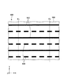
図9に示すように、本実施形態の検出用画像800は、エピポーラ線ELに交差(本実施形態では直交)して延在し、互いにパターンが異なる第1線状パターン820および第2線状パターン830を有し、第1、第2線状パターン820、830がエピポーラ線ELの延在方向に沿って交互に並んで配置されている。第1線状パターン820は、延在方向に輝度が一定のパターンとなっており、第2線状パターン830は、第1輝度を有する部分と、第1輝度と異なる第2輝度を有する部分とが交互にかつ周期的(等間隔)に並んだパターンとなっている。
スクリーン900の下側ほど、カメラ400との角度が小さくなるため、カメラ400が取得する画像では、図10に示すように、スクリーン900の下側へ向けて第1、第2線状パターン820、830のピッチが漸減すると共に、第1、第2線状パターン820、830の幅も漸減する。そのため、カメラ400の分解能(解像度)によっては、スクリーン900の上部に写る検出用画像800(第1、第2線状パターン820、830)については鮮明に認識することができても、スクリーン900の下部に写る検出用画像800(第1、第2線状パターン820、830)については鮮明に認識することが困難な場合も考えられる。
そのため、スクリーン900の下部では消失部890の最も上側(先端側)に位置するのが第1、第2線状パターン820、830のどちらであるのかを認識することができないおそれがある。一方、図11に示すように、指Fは、スクリーン900の下部に位置していてもカメラ400との角度が大きくなるため、指F上に写った第1、第2線状パターン820、830については鮮明に認識することができる。そのため、指Fの最も先端側に位置するのが第1、第2線状パターン820、830のどちらであるかを認識することで、消失部890の最も先端側に位置するのが第1、第2線状パターン820、830のどちらであるかを判断することができる。これは、指Fの最も先端側に位置する線状パターンと、消失部890の最も先端側に位置する線状パターンは、同列のパターンとなるためである。したがって、本実施形態によれば、カメラ400の分解能よりも高い分解能で、タッチ認識を行うことができると共に、タッチ位置のXY座標を取得することができる。
以上のような第3実施形態によっても、上述した第1実施形態と同様の効果を発揮することができる。なお、本実施形態では、検出用画像が、第1線状パターン820および第2線状パターン830が、エピポーラ線ELの延在方向に沿って交互に配置された構成となっているが、検出用画像としては特に限定されない。例えば、第1、第2線状パターン820、830と異なる第3線状パターンを有していてもよい。
<第4実施形態>
次に、本発明の第4実施形態に係る画像認識ユニットについて説明する。
次に、本発明の第4実施形態に係る画像認識ユニットについて説明する。
図12は、本発明の第4実施形態に係る画像認識ユニットで用いられる検出用画像を示す図である。図13は、図12に示す検出用画像の変形例を示す図である。
以下、本発明の第4実施形態に係る画像認識ユニットについて説明するが、前述した実施形態との相違点を中心に説明し、同様の事項はその説明を省略する。
第4実施形態の画像認識ユニットは、検出用画像が異なること以外は、前述した第1実施形態と同様である。なお、前述した実施形態と同様の構成には、同一符号を付してある。
前述した第1実施形態の問題として以下の問題が挙げられる。すなわち、指Fがスクリーン900の法線方向(Z軸方向)とは異なる方向に沿ってスクリーン900に接近する場合には、スクリーン900と指Fの離間距離に応じて距離Dが変化するため、距離Dに基づいてタッチ認識を行うことができるが、指Fがスクリーン900の法線方向に沿ってスクリーン900に接近する場合には、スクリーン900と指Fの離間距離が変化しても距離Dが変化しないため、正確なタッチ認識を行うことができなくなる。このような問題は、特に、カメラ400の分解能が高いスクリーン900の上部において発生する。そこで、本実施形態では、指Fがスクリーン900の法線方向に沿ってスクリーン900に接近する場合でも、正確なタッチ認識を行うことができるような検出用画像800としている。
図12に示すように、本実施形態の検出用画像800は、スクリーン900の上部(カメラ400から近い側)に位置する第1領域800Aと、スクリーン900の下部(カメラ400から遠い側)に位置する第2領域800Bと、を有している。そして、第1領域800Aには、エピポーラ線ELに沿って延在する線状パターン850がエピポーラ線ELと直交する方向に沿って等ピッチに複数配置されている。一方、第2領域800Bには、エピポーラ線ELに交差(本実施形態では直交)する線状パターン860がエピポーラ線ELの延在方向に沿って等ピッチに複数配置されている。このような構成とすることで、第1領域800Aにおいて、指Fがスクリーン900の法線方向に沿ってスクリーン900に接近する場合でも、より確実に、タッチ認識を行うことができる。
以上のような第4実施形態によっても、上述した第1実施形態と同様の効果を発揮することができる。なお、本実施形態の検出用画像800の変形例として、図13に示すような検出用画像800としてもよい。図13に示す検出用画像800では、第2領域800Bに、エピポーラ線ELに直交(交差)し、互いにパターンが異なる線状パターン861、862、863がエピポーラ線ELの延在方向に沿って等ピッチにかつ交互に並んで複数配置されている。このような構成によれば、前述した第3実施形態と同様に、スクリーン900の下部においても、精度よくタッチ認識を行うことができる。
<第5実施形態>
次に、本発明の第5実施形態に係る画像認識ユニットについて説明する。
図14は、本発明の第5実施形態に係る画像認識ユニットの構成を示す側面図である。
次に、本発明の第5実施形態に係る画像認識ユニットについて説明する。
図14は、本発明の第5実施形態に係る画像認識ユニットの構成を示す側面図である。
以下、本発明の第5実施形態に係る画像認識ユニットについて説明するが、前述した実施形態との相違点を中心に説明し、同様の事項はその説明を省略する。
第5実施形態の画像認識ユニットは、撮像素子および検出用画像表示装置の配置が異なること以外は、前述した第1実施形態と同様である。なお、前述した実施形態と同様の構成には、同一符号を付してある。
図14に示すように、本実施形態では、第3象限S3にカメラ400が配置されている。また、プロジェクター300は、例えば床に設置されており、比較的低い位置から斜め上側に向けて光を出射するように配置されている。そして、プロジェクター300からはスクリーン900の法線と一致する光軸を持つ光が出射されず、第1仮想面f1および第2仮想面f2が、共に、スクリーン900側がプロジェクター300側よりも上方に位置するように傾斜している。プロジェクター300およびカメラ400をこのような配置とすることで、プロジェクター300とスクリーン900との間に指Fが存在したときに、消失部890をカメラ400でより確実に撮像することができる。
なお、本実施形態は、前述した第1実施形態の構成を上下反転させた構成であり、第1実施形態の説明を上下反転すれば本実施形態の説明となる。したがって、本実施形態の詳細な説明は省略する。
以上のような第5実施形態によっても、上述した第1実施形態と同様の効果を発揮することができる。
<第6実施形態>
次に、本発明の第6実施形態に係る画像認識ユニットについて説明する。
図15は、本発明の第6実施形態に係る画像認識ユニットの構成を示す側面図である。
次に、本発明の第6実施形態に係る画像認識ユニットについて説明する。
図15は、本発明の第6実施形態に係る画像認識ユニットの構成を示す側面図である。
以下、本発明の第6実施形態に係る画像認識ユニットについて説明するが、前述した実施形態との相違点を中心に説明し、同様の事項はその説明を省略する。
第6実施形態の画像認識ユニットは、検出用画像表示装置の配置が異なること以外は、前述した第1実施形態と同様である。なお、前述した実施形態と同様の構成には、同一符号を付してある。
図15に示すように、本実施形態では、プロジェクター300からスクリーン900の法線と一致する光軸を持つ光が出射され、第1仮想面f1は、スクリーン900側がプロジェクター300側よりも上方に位置するように傾斜しており、第2仮想面f2は、スクリーン900側がプロジェクター300側よりも下方に位置するように傾斜している。
以上のような第6実施形態によっても、上述した第1実施形態と同様の効果を発揮することができる。
以上、本発明の画像認識装置、画像認識方法および画像認識ユニットについて、図示の実施形態に基づいて説明したが、本発明はこれに限定されるものではない。例えば、本発明の画像認識装置では、各部の構成は、同様の機能を有する任意の構成のものに置換することができ、また、他の任意の構成を付加することもできる。
また、前述した実施形態では、Y軸が鉛直方向に沿って配置されているが、Y軸は鉛直方向に沿っていなくてもよい。すなわち、前述実施形態に対して、Y軸がX軸まわりに所定角度回転していてもよいし、Y軸がZ軸まわりに所定角度回転していてもよい。
100…画像認識ユニット、200…画像表示ユニット、300…プロジェクター、400…カメラ、500…画像認識装置、510…画像処理部、700…プロジェクター、800…検出用画像、800A…第1領域、800B…第2領域、810…線状パターン、811、812…線状パターン、811a、812a…消失部分、820…第1線状パターン、830…第2線状パターン、850、860…線状パターン、861、862、863…線状パターン、890…消失部、900…スクリーン、C1…カメラ中心、C2…プロジェクター中心、D…距離、EL、EL’…エピポーラ線、F…指、Lf…線分、l1、l2、l3…直線、M…マーカー、P1、P2…位置、P811、P812…中点、Pe…エピポーラ点、Pm…頂点、S1…第1象限、S2…第2象限、S3…第3象限、f1…第1仮想面、f2…第2仮想面、x…座標、Σ…エピポーラ平面、π1…画像平面、π2…仮想画像平面
Claims (11)
- 画像表示面に検出用画像を表示する検出用画像表示装置と、前記画像表示面を撮像する撮像装置と、を有し、前記検出用画像の鉛直方向上側の端を形成する光線群を含む面を第1仮想面、前記検出用画像の鉛直方向下側の端を形成する光線群を含む面を第2仮想面、前記画像表示面と前記検出用画像表示装置との間に位置し、前記第1仮想面と前記第2仮想面とに挟まれた領域を第1象限、前記第1象限の鉛直方向上側に位置する領域を第2象限、前記第1象限の鉛直方向下側に位置する領域を第3象限としたとき、前記第2象限または前記第3象限に前記撮像装置が配置されている画像表示ユニットで用いられる画像認識装置であって、
前記撮像装置が取得した画像に基づいて、前記検出用画像表示装置と前記画像表示面との間に対象物が位置したときに前記対象物によって前記検出用画像表示装置からの光が遮られることで前記画像表示面上に生じる消失部と、前記撮像装置と前記検出用画像表示装置の位置関係から決定され、かつ、前記消失部を通るエピポーラ線上にあって、前記対象物上に表示される前記検出用画像と、の距離を検知し、検知結果に基づいて前記対象物が前記画像表示面に接触しているか否かを判断する画像処理部を有することを特徴とする画像認識装置。 - 前記検出用画像は、前記エピポーラ線に交差する線状パターンを有している請求項1に記載の画像認識装置。
- 前記撮像装置は、前記第2象限に配置され、
前記第1仮想面および前記第2仮想面は、共に、前記画像表示面側が前記検出用画像表示装置側よりも下方に位置するように傾斜している請求項1または2に記載の画像認識装置。 - 前記撮像装置は、前記第3象限に配置され、
前記第1仮想面および前記第2仮想面は、共に、前記画像表示面側が前記検出用画像表示装置側よりも上方に位置するように傾斜している請求項1または2に記載の画像認識装置。 - 前記線状パターンの前記消失部によって消失した消失部分は、前記対象物上に表示され、
前記画像処理部は、前記消失部分の前記対象物が無い場合に表示されている位置と、前記対象物上に表示されている実際の位置と、の前記エピポーラ線に沿った距離を検出する請求項1ないし4のいずれか1項に記載の画像認識装置。 - 前記画像処理部は、前記消失部の形状に基づいて、前記対象物の先端部の位置を推定する位置推定部を有している請求項1ないし5のいずれか1項に記載の画像認識装置。
- 前記検出用画像は、前記エピポーラ線に交差して延在し、互いにパターンが異なる第1線状パターンおよび第2線状パターンを有し、
前記第1線状パターンおよび前記第2線状パターンが前記エピポーラ線の延在方向に沿って交互に並んで配置されている請求項1ないし6のいずれか1項に記載の画像認識装置。 - 前記検出用画像は、前記撮像装置から近い側に位置する第1領域と、前記第1領域よりも前記撮像装置から遠い側に位置する第2領域と、を有し、
前記第1領域には前記エピポーラ線に沿って延在する線状パターンが配置され、前記第2領域には前記エピポーラ線に交差する線状パターンが配置されている請求項1ないし6のいずれか1項に記載の画像認識装置。 - 画像表示面に検出用画像を表示する検出用画像表示装置と、前記画像表示面を撮像する撮像装置と、を有し、前記検出用画像の鉛直方向上側の端を形成する光線群を含む面を第1仮想面、前記検出用画像の鉛直方向下側の端を形成する光線群を含む面を第2仮想面、前記画像表示面と前記検出用画像表示装置との間に位置し、前記第1仮想面と前記第2仮想面とに挟まれた領域を第1象限、前記第1象限の鉛直方向上側に位置する領域を第2象限、前記第1象限の鉛直方向下側に位置する領域を第3象限としたとき、前記第2象限または前記第3象限に前記撮像装置が配置されている画像表示ユニットで用いられる画像認識方法であって、
前記撮像装置が取得した画像に基づいて、前記検出用画像表示装置と前記画像表示面との間に対象物が位置したときに前記対象物によって前記検出用画像表示装置からの光が遮られることで前記画像表示面上に生じる消失部と、前記撮像装置と前記検出用画像表示装置の位置関係から決定され、かつ、前記消失部を通るエピポーラ線上にあって、前記対象物上に表示される前記検出用画像と、の距離を検知し、検知結果に基づいて前記対象物が前記画像表示面に接触しているか否かを判断する判断ステップを有することを特徴とする画像認識方法。 - 請求項1ないし8のいずれか1項に記載の画像認識装置と、
前記検出用画像表示装置と、
前記撮像装置と、を有することを特徴とする画像認識ユニット。 - 前記画像表示面に画像を表示する画像表示装置を有する請求項10に記載の画像認識ユニット。
Priority Applications (2)
| Application Number | Priority Date | Filing Date | Title |
|---|---|---|---|
| CN201780021132.4A CN109073363B (zh) | 2016-03-30 | 2017-03-22 | 图像识别装置、图像识别方法以及图像识别单元 |
| US16/090,117 US10664104B2 (en) | 2016-03-30 | 2017-03-22 | Image recognition device, image recognition method, and image recognition unit |
Applications Claiming Priority (2)
| Application Number | Priority Date | Filing Date | Title |
|---|---|---|---|
| JP2016068276A JP6607121B2 (ja) | 2016-03-30 | 2016-03-30 | 画像認識装置、画像認識方法および画像認識ユニット |
| JP2016-068276 | 2016-03-30 |
Publications (1)
| Publication Number | Publication Date |
|---|---|
| WO2017170027A1 true WO2017170027A1 (ja) | 2017-10-05 |
Family
ID=59965444
Family Applications (1)
| Application Number | Title | Priority Date | Filing Date |
|---|---|---|---|
| PCT/JP2017/011420 WO2017170027A1 (ja) | 2016-03-30 | 2017-03-22 | 画像認識装置、画像認識方法および画像認識ユニット |
Country Status (4)
| Country | Link |
|---|---|
| US (1) | US10664104B2 (ja) |
| JP (1) | JP6607121B2 (ja) |
| CN (1) | CN109073363B (ja) |
| WO (1) | WO2017170027A1 (ja) |
Families Citing this family (6)
| Publication number | Priority date | Publication date | Assignee | Title |
|---|---|---|---|---|
| JP6668764B2 (ja) | 2016-01-13 | 2020-03-18 | セイコーエプソン株式会社 | 画像認識装置、画像認識方法および画像認識ユニット |
| JP6668763B2 (ja) | 2016-01-13 | 2020-03-18 | セイコーエプソン株式会社 | 画像認識装置、画像認識方法および画像認識ユニット |
| JP6631261B2 (ja) | 2016-01-14 | 2020-01-15 | セイコーエプソン株式会社 | 画像認識装置、画像認識方法および画像認識ユニット |
| JP7263983B2 (ja) * | 2019-08-30 | 2023-04-25 | 富士通株式会社 | 撮影漏れ検出装置、及び、撮影漏れ検出方法 |
| CN112054859B (zh) * | 2019-11-25 | 2023-12-29 | 陕西智航信科技有限公司 | 天线强度失配分析系统及方法 |
| CN113409290B (zh) * | 2021-06-29 | 2023-12-15 | 北京兆维电子(集团)有限责任公司 | 一种液晶屏外观缺陷检测方法、装置及存储介质 |
Citations (4)
| Publication number | Priority date | Publication date | Assignee | Title |
|---|---|---|---|---|
| JPS59109904U (ja) * | 1983-01-14 | 1984-07-24 | 株式会社東京精密 | 触針式形状測定機の測定位置検知装置 |
| JP2000298544A (ja) * | 1999-04-12 | 2000-10-24 | Matsushita Electric Ind Co Ltd | 入出力装置と入出力方法 |
| JP2014179032A (ja) * | 2013-03-15 | 2014-09-25 | Ricoh Co Ltd | 仮想キー入力装置 |
| JP2016139396A (ja) * | 2014-08-25 | 2016-08-04 | キヤノン株式会社 | ユーザーインターフェイス装置、方法およびプログラム |
Family Cites Families (23)
| Publication number | Priority date | Publication date | Assignee | Title |
|---|---|---|---|---|
| JP2004077290A (ja) | 2002-08-19 | 2004-03-11 | Fuji Xerox Co Ltd | 3次元形状計測装置および方法 |
| JP4507806B2 (ja) * | 2004-10-01 | 2010-07-21 | 三菱電機株式会社 | 指紋画像撮像装置 |
| US9330324B2 (en) | 2005-10-11 | 2016-05-03 | Apple Inc. | Error compensation in three-dimensional mapping |
| JP5001286B2 (ja) | 2005-10-11 | 2012-08-15 | プライム センス リミティド | 対象物再構成方法およびシステム |
| CN101496033B (zh) | 2006-03-14 | 2012-03-21 | 普莱姆森斯有限公司 | 利用散斑图案的三维传感 |
| KR101408959B1 (ko) | 2006-03-14 | 2014-07-02 | 프라임센스 엘티디. | 삼차원 감지를 위한 깊이 가변 광 필드 |
| EP1994503B1 (en) | 2006-03-14 | 2017-07-05 | Apple Inc. | Depth-varying light fields for three dimensional sensing |
| CN101231450B (zh) * | 2008-02-25 | 2010-12-22 | 陈伟山 | 多点及物体触摸屏装置及多点触摸的定位方法 |
| US8120642B2 (en) * | 2008-07-25 | 2012-02-21 | Honeywell International Inc. | Optical fingerprint acquisition |
| JP5423222B2 (ja) * | 2009-08-07 | 2014-02-19 | ソニー株式会社 | 位置検出装置および位置検出方法 |
| JP5304848B2 (ja) | 2010-10-14 | 2013-10-02 | 株式会社ニコン | プロジェクタ |
| TWI529572B (zh) * | 2011-02-23 | 2016-04-11 | 原相科技股份有限公司 | 操控物的偵測方法及觸控裝置 |
| KR101295760B1 (ko) * | 2011-03-10 | 2013-08-13 | 주식회사 미르기술 | 다중 격자 무늬를 이용한 비전검사장치 |
| CN102841733B (zh) * | 2011-06-24 | 2015-02-18 | 株式会社理光 | 虚拟触摸屏系统以及自动切换交互模式的方法 |
| US10140011B2 (en) * | 2011-08-12 | 2018-11-27 | Microsoft Technology Licensing, Llc | Touch intelligent targeting |
| US8854433B1 (en) * | 2012-02-03 | 2014-10-07 | Aquifi, Inc. | Method and system enabling natural user interface gestures with an electronic system |
| EP2749996B1 (en) * | 2012-12-28 | 2018-05-30 | Sony Mobile Communications Inc. | Electronic device and method for improving accuracy of location determination of a user input on a touch panel |
| JP6089722B2 (ja) * | 2013-01-23 | 2017-03-08 | 富士通株式会社 | 画像処理装置、画像処理方法および画像処理プログラム |
| US20140267031A1 (en) * | 2013-03-12 | 2014-09-18 | Kenneth J. Huebner | Spatially aware pointer for mobile appliances |
| CN103383731B (zh) | 2013-07-08 | 2016-12-28 | 深圳先进技术研究院 | 一种基于指尖定位的投影交互方法、系统及计算设备 |
| JP6668763B2 (ja) | 2016-01-13 | 2020-03-18 | セイコーエプソン株式会社 | 画像認識装置、画像認識方法および画像認識ユニット |
| JP6668764B2 (ja) | 2016-01-13 | 2020-03-18 | セイコーエプソン株式会社 | 画像認識装置、画像認識方法および画像認識ユニット |
| JP6631261B2 (ja) | 2016-01-14 | 2020-01-15 | セイコーエプソン株式会社 | 画像認識装置、画像認識方法および画像認識ユニット |
-
2016
- 2016-03-30 JP JP2016068276A patent/JP6607121B2/ja active Active
-
2017
- 2017-03-22 US US16/090,117 patent/US10664104B2/en active Active
- 2017-03-22 WO PCT/JP2017/011420 patent/WO2017170027A1/ja active Application Filing
- 2017-03-22 CN CN201780021132.4A patent/CN109073363B/zh active Active
Patent Citations (4)
| Publication number | Priority date | Publication date | Assignee | Title |
|---|---|---|---|---|
| JPS59109904U (ja) * | 1983-01-14 | 1984-07-24 | 株式会社東京精密 | 触針式形状測定機の測定位置検知装置 |
| JP2000298544A (ja) * | 1999-04-12 | 2000-10-24 | Matsushita Electric Ind Co Ltd | 入出力装置と入出力方法 |
| JP2014179032A (ja) * | 2013-03-15 | 2014-09-25 | Ricoh Co Ltd | 仮想キー入力装置 |
| JP2016139396A (ja) * | 2014-08-25 | 2016-08-04 | キヤノン株式会社 | ユーザーインターフェイス装置、方法およびプログラム |
Also Published As
| Publication number | Publication date |
|---|---|
| JP6607121B2 (ja) | 2019-11-20 |
| US20190114033A1 (en) | 2019-04-18 |
| CN109073363B (zh) | 2020-07-10 |
| CN109073363A (zh) | 2018-12-21 |
| US10664104B2 (en) | 2020-05-26 |
| JP2017181281A (ja) | 2017-10-05 |
Similar Documents
| Publication | Publication Date | Title |
|---|---|---|
| JP6607121B2 (ja) | 画像認識装置、画像認識方法および画像認識ユニット | |
| JP4913344B2 (ja) | ポインタ追跡方法、ポインタ接触位置検出方法、およびタッチシステム | |
| JP6621836B2 (ja) | 光パターンの強度変動を利用した体積内の物体の深さマッピング | |
| US20130106833A1 (en) | Method and apparatus for optical tracking of 3d pose using complex markers | |
| US9879984B2 (en) | Optical scanning probe and apparatus for generating three-dimensional data using the same | |
| US20100110384A1 (en) | Floating image interaction device and its program | |
| US20110316813A1 (en) | Optical touch display | |
| US9736440B2 (en) | Holographic projection device capable of forming a holographic image without misalignment | |
| JP2005122746A (ja) | 干渉パターンを用いた動き追跡方法およびシステム | |
| US10048808B2 (en) | Input operation detection device, projection apparatus, interactive whiteboard, digital signage, and projection system | |
| US10499039B2 (en) | Path detection system and path detection method generating laser pattern by diffractive optical element | |
| JP2017146938A (ja) | 書籍検出装置、書籍検出方法及び書籍検出用コンピュータプログラム | |
| US20150338923A1 (en) | Method and system for generating user feedback of a gesture capturing device | |
| TW201602839A (zh) | 光學觸控系統 | |
| US8912482B2 (en) | Position determining device and method for objects on a touch device having a stripped L-shaped reflecting mirror and a stripped retroreflector | |
| JP6740042B2 (ja) | 位置検知システム | |
| JP2018085553A (ja) | プロジェクターシステム | |
| WO2013191888A1 (en) | Device allowing tool-free interactivity with a projected image | |
| Matsubara et al. | Touch detection method for non-display surface using multiple shadows of finger | |
| JP6315127B2 (ja) | 入力装置、空中像インタラクションシステム、及び入力方法 | |
| Tsujimura et al. | Geometrical optics analysis of projected-marker augmented reality system for robot navigation | |
| JP2013191005A (ja) | デジタイザ装置 | |
| JP6512058B2 (ja) | 投影装置、映像投影方法及び映像投影用コンピュータプログラム | |
| KR101684270B1 (ko) | 표면윤곽 변화를 고려한 동적 프로젝션 매핑 방법 | |
| US8963835B2 (en) | Method for displaying an item on a display unit |
Legal Events
| Date | Code | Title | Description |
|---|---|---|---|
| NENP | Non-entry into the national phase |
Ref country code: DE |
|
| 121 | Ep: the epo has been informed by wipo that ep was designated in this application |
Ref document number: 17774568 Country of ref document: EP Kind code of ref document: A1 |
|
| 122 | Ep: pct application non-entry in european phase |
Ref document number: 17774568 Country of ref document: EP Kind code of ref document: A1 |