WO2017169937A1 - 軌道輪成形方法 - Google Patents
軌道輪成形方法 Download PDFInfo
- Publication number
- WO2017169937A1 WO2017169937A1 PCT/JP2017/011070 JP2017011070W WO2017169937A1 WO 2017169937 A1 WO2017169937 A1 WO 2017169937A1 JP 2017011070 W JP2017011070 W JP 2017011070W WO 2017169937 A1 WO2017169937 A1 WO 2017169937A1
- Authority
- WO
- WIPO (PCT)
- Prior art keywords
- ring
- polishing
- work
- blank
- thrust bearing
- Prior art date
- Legal status (The legal status is an assumption and is not a legal conclusion. Google has not performed a legal analysis and makes no representation as to the accuracy of the status listed.)
- Ceased
Links
Images































Classifications
-
- B—PERFORMING OPERATIONS; TRANSPORTING
- B21—MECHANICAL METAL-WORKING WITHOUT ESSENTIALLY REMOVING MATERIAL; PUNCHING METAL
- B21D—WORKING OR PROCESSING OF SHEET METAL OR METAL TUBES, RODS OR PROFILES WITHOUT ESSENTIALLY REMOVING MATERIAL; PUNCHING METAL
- B21D53/00—Making other particular articles
- B21D53/10—Making other particular articles parts of bearings; sleeves; valve seats or the like
-
- B—PERFORMING OPERATIONS; TRANSPORTING
- B24—GRINDING; POLISHING
- B24B—MACHINES, DEVICES, OR PROCESSES FOR GRINDING OR POLISHING; DRESSING OR CONDITIONING OF ABRADING SURFACES; FEEDING OF GRINDING, POLISHING, OR LAPPING AGENTS
- B24B19/00—Single-purpose machines or devices for particular grinding operations not covered by any other main group
- B24B19/02—Single-purpose machines or devices for particular grinding operations not covered by any other main group for grinding grooves, e.g. on shafts, in casings, in tubes, homokinetic joint elements
- B24B19/06—Single-purpose machines or devices for particular grinding operations not covered by any other main group for grinding grooves, e.g. on shafts, in casings, in tubes, homokinetic joint elements for grinding races, e.g. roller races
-
- F—MECHANICAL ENGINEERING; LIGHTING; HEATING; WEAPONS; BLASTING
- F16—ENGINEERING ELEMENTS AND UNITS; GENERAL MEASURES FOR PRODUCING AND MAINTAINING EFFECTIVE FUNCTIONING OF MACHINES OR INSTALLATIONS; THERMAL INSULATION IN GENERAL
- F16C—SHAFTS; FLEXIBLE SHAFTS; ELEMENTS OR CRANKSHAFT MECHANISMS; ROTARY BODIES OTHER THAN GEARING ELEMENTS; BEARINGS
- F16C19/00—Bearings with rolling contact, for exclusively rotary movement
- F16C19/22—Bearings with rolling contact, for exclusively rotary movement with bearing rollers essentially of the same size in one or more circular rows, e.g. needle bearings
- F16C19/30—Bearings with rolling contact, for exclusively rotary movement with bearing rollers essentially of the same size in one or more circular rows, e.g. needle bearings for axial load mainly
-
- F—MECHANICAL ENGINEERING; LIGHTING; HEATING; WEAPONS; BLASTING
- F16—ENGINEERING ELEMENTS AND UNITS; GENERAL MEASURES FOR PRODUCING AND MAINTAINING EFFECTIVE FUNCTIONING OF MACHINES OR INSTALLATIONS; THERMAL INSULATION IN GENERAL
- F16C—SHAFTS; FLEXIBLE SHAFTS; ELEMENTS OR CRANKSHAFT MECHANISMS; ROTARY BODIES OTHER THAN GEARING ELEMENTS; BEARINGS
- F16C33/00—Parts of bearings; Special methods for making bearings or parts thereof
- F16C33/30—Parts of ball or roller bearings
- F16C33/58—Raceways; Race rings
-
- F—MECHANICAL ENGINEERING; LIGHTING; HEATING; WEAPONS; BLASTING
- F16—ENGINEERING ELEMENTS AND UNITS; GENERAL MEASURES FOR PRODUCING AND MAINTAINING EFFECTIVE FUNCTIONING OF MACHINES OR INSTALLATIONS; THERMAL INSULATION IN GENERAL
- F16C—SHAFTS; FLEXIBLE SHAFTS; ELEMENTS OR CRANKSHAFT MECHANISMS; ROTARY BODIES OTHER THAN GEARING ELEMENTS; BEARINGS
- F16C33/00—Parts of bearings; Special methods for making bearings or parts thereof
- F16C33/30—Parts of ball or roller bearings
- F16C33/58—Raceways; Race rings
- F16C33/64—Special methods of manufacture
Definitions
- the present invention relates to a bearing ring forming method, and more particularly to a method for forming a bearing ring of a thrust bearing.
- the structure of a press production line for a conventional thrust bearing raceway is generally formed by bending a washer shape or the outer periphery or inner periphery of a washer from a coil material (Rz 1.5 ⁇ m or less, about Ra 0.2 ⁇ m) by a transfer press. It is processed into a shape. After that, finish processing (barrel processing or the like) was required as shown in FIG. 23 to the surface roughness required for product accuracy.
- Barrel processing is a polishing processing technique in which a workpiece 2 and a barrel media 3 are placed in a polishing tank called a barrel 1 and interact with each other as shown in FIG. It is described in Patent Document 1 that such barrel finishing is performed on the bearing ring of the thrust bearing. In addition, there is a technique that performs blasting as a finish (Patent Document 2).
- the bearing ring of the thrust bearing is subjected to a heat treatment process after a molding process such as a blank process, a piercing process, and a burring process from the coil material, and then polished as a finish.
- Processing for example, barrel processing
- the present invention provides a bearing ring forming method that can form a bearing ring without depending on the surface roughness of the material, and can reduce intermediate stock by forming a line.
- the method for forming a bearing ring for a thrust bearing according to the present invention performs a surface polishing process on a plate-shaped workpiece in a press line having a plurality of types of pressing processes.
- the bearing ring forming method for a thrust bearing of the present invention since the workpiece has a flat plate shape in the surface polishing step, the entire workpiece surface can be polished uniformly and at high speed.
- It has a blank process as a pressing process and has the surface polishing process before the blank process, or has a piercing process as the pressing process and has the surface polishing process before the piercing process.
- the burring process or the drawing process may be included as the pressing process, and the surface polishing process may be performed before the burring process or the drawing process.
- the bearing ring to be molded is an inner ring
- the bearing ring to be molded is an outer ring
- the bearing ring to be molded is a washer-shaped inner ring
- the bearing ring to be molded is a washer-shaped outer ring.
- the surface polishing step may include at least one of wheel polishing, brush polishing, belt polishing, and shot processing.
- the entire workpiece surface can be polished uniformly and at high speed. That is, even when a coil material having a rough material roughness (for example, Ra 3 ⁇ m or less) is used, polishing can be performed in a short time (for example, several seconds). Further, by putting the polishing process between the press lines, it is possible to form a line without having an intermediate stock. For this reason, cost reduction and productivity improvement can be aimed at.
- a coil material having a rough material roughness for example, Ra 3 ⁇ m or less
- FIG. 3 is a sectional view of a three-way integral thrust bearing, showing a thrust bearing.
- FIG. 3 is a sectional view of a thrust bearing integrated with a two-position outer ring, showing a thrust bearing. It is a sectional view of a thrust bearing showing a thrust bearing and integrated with a two-position inner ring.
- FIG. 3 is a cross-sectional view of a thrust bearing showing a thrust bearing and having a washer-shaped bearing ring. It is process drawing which shows the inner periphery bending process of the inner ring
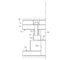
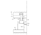
- FIG. 2 is a cross-sectional view immediately before pressing, showing a pressing device that performs an inner ring forming piercing step. It is sectional drawing after the press work which shows the press apparatus which performs the piercing process of inner ring
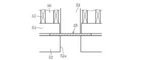
- FIG. 5 is a simplified diagram showing a piercing process of inner ring forming and during press working.
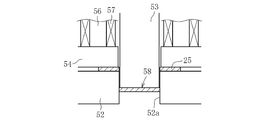
- FIG. 5 is a simplified diagram showing a piercing process for inner ring forming and after press working. It is a sectional view of the state of a set showing a press device which performs a burring process of inner ring forming.
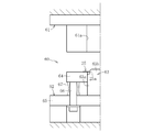
- FIG. 2 is a cross-sectional view immediately before pressing showing a pressing device that performs a burring step of inner ring molding. It is sectional drawing after the press work which shows the press apparatus which performs the burring process of inner ring
- FIG. 1 is a cross-sectional view immediately before pressing showing a pressing device that performs a draw process of outer ring molding. It is sectional drawing after the press work which shows the press apparatus which performs the draw process of outer ring shaping
- FIG. 6 is a simplified diagram showing a drawing process of outer ring molding and during press working. It is a simplified diagram of a workpiece after press working showing a draw process of outer ring forming.
- FIG. 5 is a simplified diagram showing a drawing process of outer ring molding after press working.
- FIG. 1 shows a simplified block diagram of a method for forming a bearing ring for a thrust bearing.
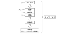
- the coil material 24 is subjected to a plurality of pressing steps (molding steps) including a polishing step (polishing step), followed by heat treatment, and then a polishing step (polishing step, for example, temper color removal).
- the temper color is a color generated by tempering. That is, the bearing ring forming method of the present invention performs a surface polishing step on a flat plate-shaped workpiece in a press line having a single or plural types of pressing steps.
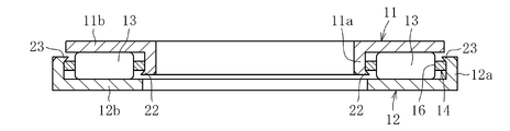
- FIG. 2A shows a three-position integrated thrust bearing
- FIG. 2B shows a two-position outer ring integrated thrust bearing
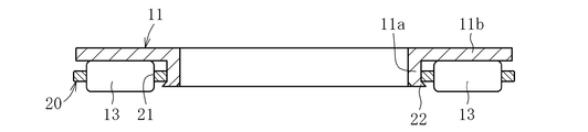
- FIG. 2C shows a two-position inner ring integrated thrust bearing
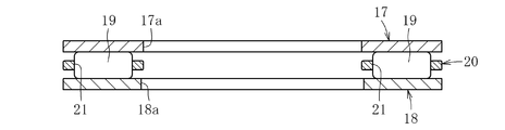
- FIG. The ring shows a washer-shaped thrust bearing.
- the three-way integral type thrust bearing shown in FIG. 2A includes a plurality of raceway rings 11 that constitute an inner ring, a raceway ring 12 that constitutes an outer ring, and rollers that are interposed between the raceway ring 11 and the raceway ring 12.
- a rolling element 13 and a cage 14 that holds the plurality of rolling elements 13 are provided.
- the bearing ring 11 constituting the inner ring is composed of a short cylindrical portion 11a and an outer flange portion 11b extending from the one open end to the outer diameter side of the short cylindrical portion 11a.
- the race 12 constituting the outer ring includes a short cylindrical portion 12a and an inner flange portion 12b extending from the one open end to the inner diameter side of the short cylindrical portion 12a.
- the cage 14 is formed of a ring body, a plurality of pockets 16 are formed at a predetermined pitch along the circumferential direction, and the rolling elements 13 are held in the pockets 16.
- a plurality of staking portions 22 and 23 are provided in the short cylindrical portion 11a of the raceway ring 11 and the short cylindrical portion 12a of the raceway ring 12, respectively.
- the thrust bearing integrated with the second outer ring in FIG. 2B does not have the bearing ring 11 in comparison with the thrust bearing integrated with the third position in FIG. 2A, and includes a bearing ring 12 constituting the outer ring and a plurality of rolling bearings.
- a moving body 13 and a holder 14 that holds the rolling element 13 are provided.
- the two-position inner ring integrated thrust bearing in FIG. 2C does not have the bearing ring 12 as compared to the three-position integrated thrust bearing in FIG. 2A, and the bearing ring 12 constituting the outer ring and a plurality of rolling bearings.
- a moving body 13 and a holder 14 that holds the rolling element 13 are provided.
- the cage 20 is formed of a ring body, a plurality of pockets 21 are formed at a predetermined pitch along the circumferential direction, and the rolling elements 19 are held in the pockets 21.
- a blank process 30 for forming a blank material 25 as a workpiece W from the coil material 24 and a hole 25a (FIGS. 4B, 4C, 5A, 5C, and 6) at a predetermined position with respect to the blank material 25 are performed.
- the molded race 11 see FIGS. 4D and 5D
- temper color removal as shown in FIG. 1 is performed. Will do.
- a polishing step (surface polishing step) 33 can be introduced before the blanking step 30 and between the piercing step 31 and the burring step 32 after the blanking step 30.
- a polishing surface 25 b is formed on the surface of the blank material 25.
- the flat plate-shaped workpiece W (blank material 25) is polished.
- surface polishing process 33 even if it is only before blank process 30, or only between piercing process 31 and burring process 32, it is two processes before blank process 30 and between piercing process 31 and burring process 32. There may be.
- two steps between the blank process 30 and after the blank process 30 and the piercing process 31 may be used.
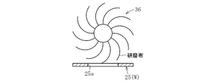
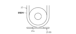
- the polishing step (polishing step) 33 includes a method as shown in FIG. 6A shows a wheel polishing process using a wheel 35 whose surface is made of an abrasive cloth or a grindstone, FIG. 6B shows a brush polishing process using a brush 36 made of an abrasive cloth, and FIG. 6C shows a belt made of an abrasive cloth.
- Fig. 6D shows a brush polishing process using a segment brush 38 having a plurality of grindstones, and
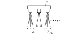
- Fig. 6E shows a shot process using a shot blasting machine 39 for ejecting media. Yes.
- the blanking process 30 uses the press apparatus 40 shown in FIG.
- the press device 40 includes an upper die 41 and a lower die 42.
- the upper die 41 has a punch 43 and a work presser 44.
- the work holder 44 is attached to the lower end of a rod 46 that is movable up and down on the substrate 45 of the upper mold 41 and is elastically pressed downward by an elastic member 47.
- the outer diameter dimension of the punch 43 and the inner diameter dimension of the punch insertion hole 42a of the lower mold 42 are set to be substantially the same.
- substantially the same means that the punch 43 can be inserted into and removed from the punch insertion hole 42a, and when inserted, there is no gap between the outer diameter surface of the punch 43 and the inner diameter surface of the punch insertion hole 42a.
- the inner diameter dimension is set larger than the outer diameter dimension of the punch 43, but when the upper die 41 is lowered, as shown in FIG. The presser can be pressed.
- the coil member 24 as shown in FIG. 8A is set on the work placement surface of the lower die 42 as shown in FIG. 7A.
- the upper mold 41 is lowered as shown in FIG. 7B.
- the end of the workpiece is pressed by the workpiece presser 44.
- the punch 43 is inserted into the punch insertion hole 42a of the lower die 42 as shown in FIGS. 7C and 8D. .
- the work retainer 44 rises against the elastic force of the elastic member 47 and maintains the state in which the end of the work W (in this case, the coil material 24) is retained by the work retainer 44.
- the disc-shaped blank 25 can be punched out.
- a blank residue 48 is sandwiched between the work holder 44 and the work placement surface of the lower mold 42.
- the piercing process uses a press device 50 shown in FIG.
- the press device 50 also includes an upper die 51 and a lower die 52.
- the upper die 51 has a punch 53 and a work presser 54.
- the work retainer 54 is attached to the lower end of a rod 56 that is movable up and down on the substrate 55 of the upper mold 51, and is elastically pressed downward by an elastic member 57.
- the outer diameter of the punch 53 and the inner diameter of the punch insertion hole 52a of the lower mold 52 are set to be substantially the same.
- substantially the same means that the punch 53 can be inserted into and removed from the punch insertion hole 52a, and when inserted, there is no gap between the outer diameter surface of the punch 53 and the inner diameter surface of the punch insertion hole 52a.
- the inner diameter dimension is set larger than the outer diameter dimension of the punch 43, but when the upper die 51 is lowered, as shown in FIG. 9B and FIG. The end can be pressed.
- a press working method using the press apparatus shown in FIG. 9 will be described.
- a blank material 25 as shown in FIGS. 8C and 10A is set on the work placement surface of the lower mold 52 as shown in FIG. 9A.
- the upper mold 51 is lowered as shown in FIG. 9B.
- the end of the blank 25 is pressed by the work holder 54.
- the punch 53 is inserted into the punch insertion hole 52a of the lower die 52 as shown in FIGS. 9C and 10D.
- the work retainer 54 rises against the elastic force of the elastic member 57 and maintains the state in which the end of the work W (the blank material 25 in this case) is pressed by the work retainer 54.
- a hole 25a is formed as shown in FIG. 10C.
- the pierce casks 58 are formed, and the pierce casks 58 enter the punch insertion holes 52 a of the lower mold 52 together with the punch 53.
- the workpiece W of the present invention is composed of the coil material 24, the blank material 25, and the like.
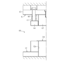
- the burring process uses a press device 60 shown in FIG.
- the press device 60 includes an upper die 61 and a lower die 62.
- the lower die 62 has a punch 63 and a work presser 64.
- the work presser 64 is attached to the upper end of a rod 66 that is movable up and down on the substrate 65 of the lower mold 62, and is elastically pressed upward by an elastic member 67.
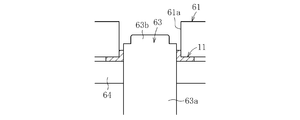
- the punch 63 is composed of a columnar main body 63a and a protruding portion 63b that is connected to the upper end of the main body 63a. Further, the outer diameter of the main body 63a is set to be substantially the same as the inner diameter of the work holder 64. Here, substantially the same means that, as shown in FIG. 11, it can be slidably inserted into the through hole of the work retainer 64, and no gap is formed between the outer diameter surface of the main body 63 a and the inner diameter surface of the work retainer 64. To the extent. Further, the inner diameter dimension of the punch insertion hole 61 a of the upper die 61 is set larger than the outer diameter dimension of the main body portion 63 a of the punch 63. In this case, a gap between the inner diameter surface of the punch insertion hole 61 a of the upper die 61 and the outer diameter surface of the main body portion 63 a of the punch 63 is set to be approximately the thickness of the blank material 25.
- the punch 63 is inserted into the punch insertion hole 61a of the upper die 61 as shown in FIGS. 11C and 12D.
- the work presser 64 descends against the elastic force of the elastic member 67 and maintains the state where the work presser 64 holds the end of the work W (in this case, the blank material 25).
- the outer peripheral part of the hole 25a of the blank material 25 can be bent upward, the short cylindrical part 11a can be formed, and the inner ring
- a staking step (caulking step) is required as shown in FIG.
- a staking part 22 is formed in the short cylindrical part 11 a of the inner ring 11 so that a part thereof bulges toward the outer diameter side.
- a leveler process is performed before the blank process, and a deburring process is performed between the piercing process 31 and the burring process 32.
- the leveler process is a process in which the material (coil material 24) sent from the uncoiler is put into the leveler and corrected.
- the polishing process is foil processing.
- the piercing process 31, the burring process 32, and the staking process are comprised with a press machine.
- FIG. 15 shows a molding process of the race 12 constituting the outer ring.
- a blank process 30 for forming a blank material 25 (see FIGS. 16A and 17A) from the coil material 24 and a piercing process for making a hole 25a (see FIGS. 16B and 17B) at a predetermined position with respect to the blank material 25.
- the molded race 12 is subjected to heat treatment, and temper color removal (polishing step) as shown in FIG. 1 is performed.
- a polishing step (polishing step) 33 can be introduced before the blank step 30 and between the piercing step 31 and the draw step 34 after the blank step 30.
- a polishing surface 25 b is formed on the surface of the blank material 25.
- the surface polishing process 33 even before the blank process 30, or only between the piercing process 31 and the draw process 34, two processes before the blank process 30 and between the piercing process 31 and the draw process 34 are performed. There may be.
- two steps between the blank process 30 and after the blank process 30 and the piercing process 31 may be used.
- the press process 70 shown in FIG. 18 is used for the drawing process.
- the press device 70 includes an upper die 71 and a lower die 72.
- the lower mold 72 has a punch 73 and a work presser 74.
- the work retainer 74 is attached to the upper end of a rod 76 that is movable up and down on the substrate 75 of the lower mold 72, and is elastically pressed upward by an elastic member 77.
- the punch 73 is composed of a columnar main body 73a and a protruding portion 73b that is connected to the upper end of the main body 73a.
- the outer diameter of the main body 73a is set to be substantially the same as the inner diameter of the work retainer 74.
- it can be slidably inserted into the through hole of the work retainer 74, and there is no gap between the outer diameter surface of the main body 73 a and the inner diameter surface of the work retainer 74. To the extent.
- a work presser 78 is disposed in the insertion hole 71 a of the upper mold 71 via an elastic member 79.
- the work retainer 78 is formed of a disk-shaped body, and a concave portion 78a is provided on the lower surface thereof. As shown in FIGS. 18B and 18C, the protruding portion 73b of the punch 73 can be fitted into the concave portion 78a. It has become.
- the outer diameter dimension of the work retainer 78 and the inner diameter dimension of the fitting hole 71a of the upper die 71 are set to be substantially the same.
- substantially the same means that the work retainer 78 can be slidably inserted into the insertion hole 71a of the upper mold 71, and a gap is formed between the outer diameter surface of the work retainer 78 and the inner diameter surface of the insertion hole 71a of the upper mold 71. Do not generate.
- the inner diameter dimension of the recessed portion 78a and the outer diameter dimension of the bulging portion 73b of the punch 73 are set to be substantially the same.
- the substantially same means that the bulged portion 73b of the punch 73 can be fitted into the recessed portion 78a of the work retainer 78, and the outer diameter surface of the bulged portion 73b of the punch 73 and the inner diameter surface of the recessed portion 78a of the work retainer 78 are It is set so as not to cause a gap between them.
- the outer diameter dimension of the work retainer 78 is set larger than the outer diameter dimension of the main body 73 a of the punch 73. That is, the gap between the inner diameter surface of the fitting hole 71 a of the upper die 71 and the outer diameter surface of the main body portion 73 a of the punch 73 is set to be approximately the thickness of the blank material 25.
- the blank 25 (see FIGS. 16B, 17B, and 19A) in which the holes 25a are formed is set on the work placement surface of the lower die 72 as shown in FIG. 18A.
- the bulging portion 73 b of the punch 73 is fitted into the hole 25 a of the blank material 25, and the blank material 25 is placed on the upper surface of the main body portion 73 a of the punch 73. That is, the upper surface of the work holder 74 and the upper surface of the main body 73a of the punch 73 are disposed on the same surface.
- the upper mold 71 is lowered as shown in FIGS. 18B and 19B. That is, the blank material 25 is sandwiched between the work retainer 78 and the upper die 71, and the upper surface of the main body 73 a of the punch 73 and the upper surface of the work retainer 74.
- the upper die 71 is further lowered from the state shown in FIGS. 18B and 19B.
- the outer peripheral portion of the blank member 25 is bent downward to form the short cylindrical portion 12a and the outer ring 12 is formed.
- the heat treatment and the post-process are performed in the same manner as the molding method of the inner ring 11 in FIG. For this reason, the polishing surface 25b is formed as shown in FIGS. 16C and 17C.
- the staking part 23 is provided like the outer ring
- FIG. 20 shows a molding process of the washer-shaped race rings 17 and 18.
- a blank process 30 for forming a blank material 25 (see FIGS. 21A and 22A) from the coil material 24 and a piercing process for making a hole 25a (see FIGS. 21B and 22B) at a predetermined position with respect to the blank material 25. 31.
- a polishing step (polishing step) 33 can be introduced before the blanking step 30, before the piercing step 31 after the blanking step 30, and after the piercing step 31.
- the polishing surface 80 is formed as shown in FIGS. 21C and 22C.
- the surface polishing process 33 even before the blank process 30, only before the piercing process 31 after the blank process 30, and only after the piercing process 32, the piercing process before the blank process 30 and after the blank process 30. It may be any two steps before 31 and after piercing step 31, or all three steps. In the process of forming the washer-shaped races 17 and 18, there is no need to provide a burring process or a drawing process.
- the workpiece W has a flat plate shape during the surface polishing step, the entire workpiece surface can be uniformly and rapidly polished. That is, even if the coil material 24 (for example, Ra 3 ⁇ m or less) having a rough material is used, polishing can be performed in a short time (for example, several seconds). Moreover, it becomes possible to form without having an intermediate stock by putting a polishing process between the press lines and making it into a line. For this reason, cost reduction and productivity improvement can be aimed at.
- the coil material 24 for example, Ra 3 ⁇ m or less
- the bearing ring to be molded may be a bearing inner ring, a bearing outer ring, a washer-shaped inner ring or an outer ring.
- the polishing process includes wheel polishing, brush polishing, belt polishing, and shot processing.
Landscapes
- Engineering & Computer Science (AREA)
- General Engineering & Computer Science (AREA)
- Mechanical Engineering (AREA)
- Manufacturing & Machinery (AREA)
- Rolling Contact Bearings (AREA)
- Grinding And Polishing Of Tertiary Curved Surfaces And Surfaces With Complex Shapes (AREA)
Abstract
単一または複数種のプレス工程を有するプレスライン内において、平板形状のワークに対して表面研磨工程を行う。プレス工程としてブランク工程を有し、このブランク工程前に前記表面研磨工程を有する。
Description
本発明は、軌道輪成形方法に関し、特に、スラスト軸受の軌道輪を成形する方法に関する。
従来のスラスト軸受の軌道輪に対するプレス生産ラインの構成は、一般には、コイル材(Rz1.5μm以下、Ra0.2μm程度)からトランスファープレスにより、ワッシャー形状または、ワッシャーの外周または内周を曲げ加工した形状に加工するものである。その後に、製品精度として必要な面粗さまで、図23に示すように仕上げ加工(バレル加工等)が必要であった。
バレル加工(バレル研磨)は、図23に示すように、バレル1とよばれる研磨槽内にワーク2とバレルメディア3を投入し、それらの相互摩擦作用させる研磨加工技術である。スラスト軸受の軌道輪に対して、このようなバレル加工の仕上げを行うことは特許文献1に記載されている。また、仕上げとして、ブラスト処理を行うものもある(特許文献2)。
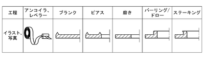
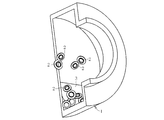
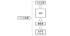
すなわち、スラスト軸受の軌道輪等は、図24に示すように、コイル材からブランク工程、ピアス工程、及びバーリング工程等の成形工程を行った後、熱処理工程を行い、次に、仕上げとして、磨き加工(例えば、バレル加工)を行うことになる。すなわち、成形工程からバレル工程までのバッチ処理を行うことになる。
従来の製造法では、成形した複雑な形状のワークの面粗さを改善させる必要があるため、処理時間が数時間と長く、図24に示すように、バッチ処理を行う必要があった。それにより、中間在庫を持つ必要があり、前後工程とのライン化もできなかった。
そこで、本発明では、材料表面粗さに依存することなく軌道輪の成形が可能であり、ライン化することにより中間在庫の削減が可能である軌道輪成形方法を提供する。
本発明のスラスト軸受用の軌道輪成形方法は、複数種のプレス工程を有するプレスライン内において、平板形状のワークに対して表面研磨工程を行うものである。
本発明のスラスト軸受用の軌道輪成形方法によれば、表面研磨工程の際には、ワークが平板形状であるので、ワーク表面全体を均一かつ高速に研磨加工することができる。
プレス工程としてブランク工程を有し、このブランク工程前に前記表面研磨工程を有するのもであったり、プレス工程としてピアス工程を有し、このピアス工程前に前記表面研磨工程を有するものであったり、プレス工程としてバーリング工程又はドロー工程を有し、バーリング工程又はドロー工程前に前記表面研磨工程を有するものであったりする。
成形する軌道輪が内輪であったり、成形する軌道輪が外輪であったり、成形する軌道輪がワッシャー形状の内輪であったり、成形する軌道輪がワッシャー形状の外輪であったりする。
前記表面研磨工程が、ホイール研磨加工、ブラシ研磨加工、ベルト研磨加工、及びショット加工の少なくともいずれか一つ工程を含むものとすることができる。
本発明では、ワーク表面全体を均一かつ高速に研磨加工することができる。すなわち、素材粗さが粗いコイル材(例えば、Ra3μm以下)を使用しても、短時間(例えば、数秒)で研磨加工ができる。また、研磨工程をプレスラインの間に入れることによって、ライン化することができて、中間在庫を持つことなく成形できるようになる。このため、低コスト化及び生産性の向上を図ることができる。
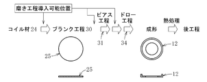
以下本発明の実施の形態を図1~図22に基づいて説明する。図1はスラスト軸受の軌道輪成形方法の簡略ブロック図を示す。この図1では、コイル材24を、みがき工程(研磨工程)を含む複数のプレス工程(成形工程)を行った後、熱処理を行い、次にみがき工程(研磨工程、例えば、テンパーカラー取り)を行うものである。なお、テンパーカラーとは、焼き戻しで発生する色のことである。すなわち、本発明の軌道輪成形方法は、単一または複数種のプレス工程を有するプレスライン内において、平板形状のワークに対して表面研磨工程を行うものである。
ところで、スラスト軸受としては、図2Aは三位一体型のスラスト軸受を示し、図2Bは二位外輪一体型のスラスト軸受を示し、図2Cは二位内輪一体型のスラスト軸受を示し、図2Cは軌道輪がワッシャー形状のスラスト軸受を示している。
すなわち、図2Aに示す三位一体型のスラスト軸受は、内輪を構成する軌道輪11と、外輪を構成する軌道輪12と、軌道輪11と軌道輪12との間に介在されるころからなる複数の転動体13と、この複数の転動体13を保持する保持器14とを備える。
内輪を構成する軌道輪11は、短円筒部11aと、この短円筒部11aに一方の開口端部から外径側に延びる外鍔部11bとからなる。また、外輪を構成する軌道輪12は、短円筒部12aと、この短円筒部12aに一方の開口端部から内径側に延びる内鍔部12bとからなる。保持器14は、リング体からなり、周方向に沿って所定ピッチで複数個のポケット16が形成され、各ポケット16に転動体13が保持されている。この図2Aに示すスラスト軸受では、軌道輪11の短円筒部11a及び軌道輪12の短円筒部12aには、それぞれ、複数個のステーキング部22,23を設けている。
図2Bの二位外輪一体型のスラスト軸受は、前記図2Aの三位一体型のスラスト軸受に対して、軌道輪11を有さないものであり、外輪を構成する軌道輪12と、複数個の転動体13と、この転動体13を保持する保持器14とを備える。図2Cの二位内輪一体型のスラスト軸受は、前記図2Aの三位一体型のスラスト軸受に対して、軌道輪12を有さないものであり、外輪を構成する軌道輪12と、複数個の転動体13と、この転動体13を保持する保持器14とを備える。
図2Eに示すスラスト軸受では、貫孔17a、18aを有するワッシャ形状(平板リング体)の一対の軌道輪17,18と、この軌道輪17,18間に介在される複数個の転動体19と、この転動体19を保持する保持器20とを備える。この場合、保持器20は、リング体からなり、周方向に沿って所定ピッチで複数個のポケット21が形成され、各ポケット21に転動体19が保持されている。
ところで、前記軌道輪11を成形する場合、図3に示すように、複数のプレス加工を経ることになる。プレス加工として、コイル材24からワークWとしてのブランク材25を形成するブランク工程30と、ブランク材25に対して所定位置に穴25a(図4B、図4C、図5A、図5C、及び図6参照)をあけるピアス工程31と、ピアス工程31にてピアス加工を施されたブランク材25にバーリング加工(突起を作る)を行うバーリング工程32とを備える。なお、図3では、バーリング工程32終了後に、成形された軌道輪11(図4D及び図5D参照)に対して、熱処理を行って、図1に示すような、テンパーカラー取り(みがき工程)を行うことになる。
この際、ブランク工程30前、及び、ブランク工程30後のピアス工程31とバーリング工程32間において、磨き工程(表面研磨工程)33を導入することができる。図4C及び図5Cに示すように、ブランク材25表面に研磨面25bを形成している。この表面研磨工程33は、平板形状のワークW(ブランク材25)を研磨することになる。なお、表面研磨工程33としては、ブランク工程30前のみであっても、ピアス工程31とバーリング工程32間のみであっても、ブランク工程30前及びピアス工程31とバーリング工程32間の2工程であってもよい。また、ブランク工程30前及びブランク工程30後とピアス工程31間の2工程であってもよい。
磨き工程(研磨工程)33には図6に示すような方法がある。図6Aは表面が研磨布または砥石で構成されたホイール35を用いたホイール研磨加工を示し、図6Bは研磨布からなるブラシ36を用いたブラシ研磨加工を示し、図6Cは研磨布からなるベルト37を用いたベルト研磨加工を示し、図6Dは複数個の砥石を有するセグメントブラシ38を用いたブラシ研磨加工を示し、図6Eはメディアを噴射するショットブラスト機39を用いたショット加工を示している。
ブランク工程30は図7に示すプレス装置40を用いる。プレス装置40は、上型41と下型42とを備える。上型41はパンチ43とワーク押え44とを有する。ワーク押え44は、上型41の基板45に上下動自在なロッド46の下端に付設され、弾性部材47にて、弾性的に下方へ押圧されている。
パンチ43の外径寸法と下型42のパンチ嵌入孔42aの内径寸法とを略同一に設定している。ここで、略同一とは、パンチ43のパンチ嵌入孔42aへの嵌脱が可能で、嵌入された際に、パンチ43の外径面とパンチ嵌入孔42aの内径面との間に隙間が生じない程度とする。また、ワーク押え44としては、その内径寸法をパンチ43の外径寸法よりも大きく設定しているが、上型41が下降した際に、図7Bに示すように、コイル材24の端部の押えが可能とする。
次に、この図7に示すプレス装置40にてプレス加工方法を説明する。まず、図8Aに示すようなコイル材24を図7Aに示すように、下型42のワーク載置面にセットする。この状態で、図7Bに示すように、上型41を下降させる。これによって、ワーク押え44にてワーク(コイル材24)の端部を押えた状態とする。この図7B及び図8Bに示す状態からさらに上型41(パンチ43)を下降させることによって、図7C及び図8Dに示すように、パンチ43が下型42のパンチ嵌入孔42aに嵌入していく。この際、ワーク押え44は、弾性部材47の弾性力に抗して上昇し、ワーク押え44にてワークW(この場合はコイル材24である)の端部を押えた状態を維持する。これによって、図8Cに示すように、円盤状のブランク材25を打ち抜くことができる。この際、ワーク押え44と下型42のワーク載置面との間にブランクカス48が挟持されている。
ピアス工程は図9に示すプレス装置50を用いる。プレス装置50も、上型51と下型52とを備える。上型51はパンチ53とワーク押え54とを有する。ワーク押え54は、上型51の基板55に上下動自在なロッド56の下端に付設され、弾性部材57にて、弾性的に下方へ押圧されている。
パンチ53の外径寸法と下型52のパンチ嵌入孔52aの内径寸法とを略同一に設定している。ここで、略同一とは、パンチ53のパンチ嵌入孔52aへの嵌脱が可能で、嵌入された際に、パンチ53の外径面とパンチ嵌入孔52aの内径面との間に隙間が生じない程度とする。また、ワーク押え54としては、その内径寸法をパンチ43の外径寸法よりも大きく設定しているが、上型51が下降した際に、図9B及び図10Bに示すように、ブランク材25の端部の押えが可能となる。
次に、この図9に示すプレス装置を用いたプレス加工方法を説明する。まず、図8C及び図10Aに示すようなブランク材25を図9Aに示すように、下型52のワーク載置面にセットする。この状態で、図9Bに示すように、上型51を下降させる。これにワーク押え54にてブランク材25の端部を押えた状態とする。この図9Bに示す状態からさらに上型51(パンチ43)を下降させることによって、図9C及び図10Dに示すように、パンチ53が下型52のパンチ嵌入孔52aに嵌入していく。この際、ワーク押え54は、弾性部材57の弾性力に抗して上昇し、ワーク押え54にてワークW(この場合はブランク材25である)の端部を押えた状態を維持する。これによって、図10Cに示すように孔部25aが形成される。この場合、ピアスカス58が形成され、このピアスカス58が下型52のパンチ嵌入孔52aにパンチ53とともに侵入していく。このため、本発明のワークWとしては、コイル材24及びブランク材25等で構成することになる
バーリング工程は図11に示すプレス装置60を用いる。プレス装置60は、上型61と下型62とを備える。下型62にはパンチ63とワーク押え64とを有する。ワーク押え64は、下型62の基板65に上下動自在なロッド66の上端に付設され、弾性部材67にて、弾性的に上方へ押圧されている。
パンチ63は、円柱状の本体部63aと、この本体部63aの上端に連設される突隆部63bとからなる。また、本体部63aの外径寸法は、ワーク押え64の内径寸法と略同一に設定される。ここで、略同一とは、図11に示すように、ワーク押え64の貫通孔にスライド自在に嵌入でき、本体部63aの外径面とワーク押え64の内径面との間に隙間が生じない程度とする。また、上型61のパンチ嵌入孔61aの内径寸法はパンチ63の本体部63aの外径寸法よりも大きく設定される。この場合、上型61のパンチ嵌入孔61aの内径面とパンチ63の本体部63aの外径面との間の隙間を、ブランク材25の肉厚程度とする。
次に、この図11に示すプレス装置60にてプレス加工する方法を説明する。まず、ピアス工程が終了して、穴25aが形成されたブランク材25(図12A等参照)を図11Aに示すように、下型62のワーク載置面にセットする。この状態では、パンチ63の膨出部63bが、ブランク材25の穴25aに嵌入されている。この状態で、図11Bに示すように、上型61を下降させる。すなわち、ワーク押え64にてブランク材25の端部を押えた状態とする (図12B参照) 。この図11Bに示す状態からさらに上型61を下降させることによって、図11C及び図12Dに示すように、パンチ63が上型61のパンチ嵌入孔61aに嵌入していく。この際、ワーク押え64は、弾性部材67の弾性力に抗して下降し、ワーク押え64にてワークW(この場合はブランク材25である)の端部を押えた状態を維持する。これによって、ブランク材25の穴25aの外周部を上方へ折り曲げることができて、短円筒部11aが形成され内輪11(図12C参照)を形成することができる。
ところで、図2Aおよび図2Bに示すように、内輪11にステーキング部22が形成される場合、図13に示すように、ステーキング工程(加締工程)を必要とする。このステーキング工程を有することによって、図14に示すように、内輪11の短円筒部11aに、その一部が外径側へくちばし状に膨出するステーキング部22が形成される。
なお、この図13では、ブランク工程前にレベラー工程を行い、ピアス工程31とバーリング工程32との間に、バリ取り工程を行う。レベラー工程とは、アンコイラから送出された材料(コイル材24)をレベラーに投入して矯正する工程である。また、磨き工程としては、ホイル加工である。また、この図13では、ピアス工程31、バーリング工程32、ステーキング工程は、プレス機により構成する。
また、成形後の焼入れとしては、公知公用の浸炭焼入れや高周波焼入れ等の熱処理を行うことになる。このように、熱処理を行うと、テンパーカラーが付着する。このため、図1では、このテンパーカラーを取るための磨き工程(研磨工程)を行っている。
次に、図15は外輪を構成する軌道輪12の成形工程を示している。プレス加工として、コイル材24からブランク材25(図16A及び図17A照)を形成するブランク工程30と、ブランク材25に対して所定位置に穴25a(図16B及び図17B参照)をあけるピアス工程31と、ピアス工程31にてピアス工程を施されたブランク材25にドロー加工を行うドロー工程34とを備える。なお、図15では、ドロー工程34終了後に、成形された軌道輪12に対して、熱処理を行って、図1に示すような、テンパーカラー取り(みがき工程)を行うことになる。
この際、ブランク工程30前、及び、ブランク工程30後のピアス工程31とドロー工程34間において、磨き工程(研磨工程)33を導入することができる。図5C及び図6Cに示すように、ブランク材25表面に研磨面25bを形成している。なお、表面研磨工程33としては、ブランク工程30前のみであっても、ピアス工程31とドロー工程34間のみであっても、ブランク工程30前及びピアス工程31とドロー工程34間の2工程であってもよい。また、ブランク工程30前及びブランク工程30後とピアス工程31間の2工程であってもよい。
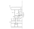
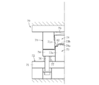
ドロー工程は図18に示すプレス装置70を用いる。プレス装置70は、上型71と下型72とを備える。下型72はパンチ73とワーク押え74とを有する。ワーク押え74は、下型72の基板75に上下動自在なロッド76の上端に付設され、弾性部材77にて、弾性的に上方へ押圧されている。
パンチ73は、円柱状の本体部73aと、この本体部73aの上端に連設される突隆部73bとからなる。また、本体部73aの外径寸法は、ワーク押え74の内径寸法と略同一に設定される。ここで、略同一とは、図18に示すように、ワーク押え74の貫通孔にスライド自在に嵌入でき、本体部73aの外径面とワーク押え74の内径面との間に隙間が生じない程度とする。
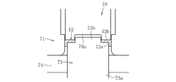
また、上型71の嵌入孔71aにはワーク押え78が弾性部材79を介して配設されている。このワーク押え78は円盤形状体からなり、その下面には凹窪部78aが設けられ、この凹窪部78aに、図18Bおよび図18Cに示すように、パンチ73の突隆部73bが嵌入可能となっている。ワーク押え78の外径寸法と上型71の嵌入孔71aの内径寸法とを略同一に設定している。ここで、略同一とは、上型71の嵌入孔71aにワーク押え78がスライド自在に嵌入でき、ワーク押え78の外径面と上型71の嵌入孔71aの内径面との間に隙間が生じない程度とする。
さらに、凹窪部78aの内径寸法とパンチ73の膨出部73bの外径寸法とは略同一に設定している。略同一とは、パンチ73の膨出部73bをワーク押え78の凹窪部78aに嵌入でき、パンチ73の膨出部73bの外径面とワーク押え78の凹窪部78aの内径面との間に隙間が生じない程度とする。ワーク押え78の外径寸法をパンチ73の本体部73aの外径寸法よりも大きく設定している。すなわち、上型71の嵌入孔71aの内径面とパンチ73の本体部73aの外径面との間の隙間を、ブランク材25の肉厚程度とする。
ピアス工程が終了して、穴25aが形成されたブランク材25(図16B、図17B、及び図19A参照)を図18Aに示すように、下型72のワーク載置面にセットする。この状態では、パンチ73の膨出部73bが、ブランク材25の穴25aに嵌入されているとともに、パンチ73の本体部73aの上面にブランク材25が載置された状態となっている。すなわち、ワーク押え74の上面とパンチ73の本体部73aの上面とが同一面上に配設されている。
この状態で、図18B及び図19Bに示すように、上型71を下降させる。すなわち、ワーク押え78及び上型71と、パンチ73の本体部73aの上面及びワーク押え74の上面とで、ブランク材25を挟持する。この図18B及び図19Bに示す状態からさらに上型71を下降させる。これによって、図16D、図18C、及び図19Dに示すように、ブランク材25の外周部が下方へ折り曲げられて、短円筒部12aが形成されて外輪12が形成される。
そして、このドロー工程後は、図3に内輪11の成形方法と同様、熱処理及び後工程(みがき工程等)を行うことになる。このため、図16C及び図17Cに示すように研磨面25bが形成される。また、図2Aおよび図2Bに示す外輪12のように、ステーキング部23が設けられるものであれば、ステーキング工程(加締工程)を必要とする。このステーキング工程を有することによって、外輪12の短円筒部12aに、その一部がくちばし状に膨出するステーキング部23が形成される。
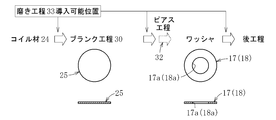
次に、図20はワッシャ形状の軌道輪17,18の成形工程を示している。プレス加工として、コイル材24からブランク材25(図21A及び図22A参照)を形成するブランク工程30と、ブランク材25に対して所定位置に穴25a(図21B及び図22B参照)をあけるピアス工程31とを備える。
この際、ブランク工程30前、ブランク工程30後のピアス工程31前、及びピアス工程31後等に磨き工程(研磨工程)33を導入することができる。これにより、図21C及び図22Cに示すように、研磨面80が形成される。表面研磨工程33としては、ブランク工程30前のみであっても、ブランク工程30後のピアス工程31前のみ、ピアス工程32後のみであっても、ブランク工程30前、ブランク工程30後のピアス工程31前、及びピアス工程31後のいずれか2工程、又はすべての3工程であってもよい。なお、ワッシャ形状の軌道輪17,18の成形工程では、バーリング工程やドロー工程を設ける必要が無い。
本発明では、表面研磨工程の際には、ワークWが平板形状であるので、ワーク表面全体を均一かつ高速に研磨加工することができる。すなわち、素材粗さが粗いコイル材24(例えば、Ra3μm以下)を使用しても、短時間(例えば、数秒)で研磨加工ができる。また、研磨工程をプレスラインの間に入れ、ライン化することで中間在庫を持つことなく成形できるようになる。このため、低コスト化及び生産性の向上を図ることができる。
成形する軌道輪として、軸受の内輪であっても、軸受の外輪であっても、ワッシャー形状の内輪や外輪であってもよい。磨き工程(表面研磨工程)には、ホイール研磨加工、ブラシ研磨加工、ベルト研磨加工、及びショット加工がある。
11 軌道輪(内輪)
12 軌道輪(外輪)
17,18 軌道輪
30 ブランク工程
31 ピアス工程
32 バーリング工程
33 表面研磨工程
34 ドロー工程
W ワーク
12 軌道輪(外輪)
17,18 軌道輪
30 ブランク工程
31 ピアス工程
32 バーリング工程
33 表面研磨工程
34 ドロー工程
W ワーク
Claims (10)
- 単一または複数種のプレス工程を有するプレスライン内において、平板形状のワークに対して表面研磨工程を行うことを特徴とするスラスト軸受用の軌道輪成形方法。
- プレス工程としてブランク工程を有し、このブランク工程前に前記表面研磨工程を有することを特徴とする請求項1に記載のスラスト軸受用の軌道輪成形方法。
- プレス工程としてピアス工程を有し、このピアス工程前に前記表面研磨工程を有することを特徴とする請求項1に記載のスラスト軸受用の軌道輪成形方法。
- プレス工程としてバーリング工程を有し、バーリング工程前に前記表面研磨工程を有することを特徴とする請求項1に記載のスラスト軸受用の軌道輪成形方法。
- プレス工程としてドロー工程を有し、ドロー工程前に前記表面研磨工程を有することを特徴とする請求項1に記載のスラスト軸受用の軌道輪成形方法。
- 成形する軌道輪が内輪であることを特徴とする請求項1~請求項4のいずれか1項に記載のスラスト軸受用の軌道輪成形方法。
- 成形する軌道輪が外輪であることを特徴とする請求項1~請求項3のいずれか1項、又は請求項5に記載のスラスト軸受用の軌道輪成形方法。
- 成形する軌道輪がワッシャー形状の内輪であることを特徴とする請求項1~請求項3のいずれか1項に記載のスラスト軸受用の軌道輪成形方法。
- 成形する軌道輪がワッシャー形状の外輪であることを特徴とする請求項1~請求項3のいずれか1項に記載のスラスト軸受用の軌道輪成形方法。
- 前記表面研磨工程が、ホイール研磨加工、ブラシ研磨加工、ベルト研磨加工、及びショット加工の少なくともいずれか一つ工程を含むことを特徴とする請求項1~請求項9のいずれか1項に記載のスラスト軸受用の軌道輪成形方法。
Applications Claiming Priority (2)
| Application Number | Priority Date | Filing Date | Title |
|---|---|---|---|
| JP2016-070932 | 2016-03-31 | ||
| JP2016070932A JP6694310B2 (ja) | 2016-03-31 | 2016-03-31 | 軌道輪成形方法 |
Publications (1)
| Publication Number | Publication Date |
|---|---|
| WO2017169937A1 true WO2017169937A1 (ja) | 2017-10-05 |
Family
ID=59965236
Family Applications (1)
| Application Number | Title | Priority Date | Filing Date |
|---|---|---|---|
| PCT/JP2017/011070 Ceased WO2017169937A1 (ja) | 2016-03-31 | 2017-03-17 | 軌道輪成形方法 |
Country Status (2)
| Country | Link |
|---|---|
| JP (1) | JP6694310B2 (ja) |
| WO (1) | WO2017169937A1 (ja) |
Cited By (1)
| Publication number | Priority date | Publication date | Assignee | Title |
|---|---|---|---|---|
| CN108906949A (zh) * | 2018-09-14 | 2018-11-30 | 苏州轴承厂股份有限公司 | 冲压外圈一次成型翻边装置 |
Citations (6)
| Publication number | Priority date | Publication date | Assignee | Title |
|---|---|---|---|---|
| US4696083A (en) * | 1984-11-09 | 1987-09-29 | Skf Gmbh, Schweinfurt | Method for making machine parts and machine parts produced thereby |
| JP2003103449A (ja) * | 2001-09-27 | 2003-04-08 | Nsk Ltd | 軸受部品の研削加工方法 |
| JP2007170448A (ja) * | 2005-12-19 | 2007-07-05 | Ntn Corp | スラストころ軸受の軌道輪およびスラストころ軸受 |
| JP2008088995A (ja) * | 2006-09-29 | 2008-04-17 | Ntn Corp | スラストころ軸受用軌道輪の製造方法およびスラストころ軸受の軌道輪形成用リング部材 |
| JP2013164093A (ja) * | 2012-02-09 | 2013-08-22 | Nsk Ltd | スラストニードル軸受用レースの製造方法 |
| JP2015208852A (ja) * | 2014-04-25 | 2015-11-24 | アクティエボラゲット・エスコーエッフ | 軸受リングのための研磨機及び当該研磨機における接触状態を設定するための方法 |
-
2016
- 2016-03-31 JP JP2016070932A patent/JP6694310B2/ja not_active Expired - Fee Related
-
2017
- 2017-03-17 WO PCT/JP2017/011070 patent/WO2017169937A1/ja not_active Ceased
Patent Citations (6)
| Publication number | Priority date | Publication date | Assignee | Title |
|---|---|---|---|---|
| US4696083A (en) * | 1984-11-09 | 1987-09-29 | Skf Gmbh, Schweinfurt | Method for making machine parts and machine parts produced thereby |
| JP2003103449A (ja) * | 2001-09-27 | 2003-04-08 | Nsk Ltd | 軸受部品の研削加工方法 |
| JP2007170448A (ja) * | 2005-12-19 | 2007-07-05 | Ntn Corp | スラストころ軸受の軌道輪およびスラストころ軸受 |
| JP2008088995A (ja) * | 2006-09-29 | 2008-04-17 | Ntn Corp | スラストころ軸受用軌道輪の製造方法およびスラストころ軸受の軌道輪形成用リング部材 |
| JP2013164093A (ja) * | 2012-02-09 | 2013-08-22 | Nsk Ltd | スラストニードル軸受用レースの製造方法 |
| JP2015208852A (ja) * | 2014-04-25 | 2015-11-24 | アクティエボラゲット・エスコーエッフ | 軸受リングのための研磨機及び当該研磨機における接触状態を設定するための方法 |
Cited By (2)
| Publication number | Priority date | Publication date | Assignee | Title |
|---|---|---|---|---|
| CN108906949A (zh) * | 2018-09-14 | 2018-11-30 | 苏州轴承厂股份有限公司 | 冲压外圈一次成型翻边装置 |
| CN108906949B (zh) * | 2018-09-14 | 2023-09-15 | 苏州轴承厂股份有限公司 | 冲压外圈一次成型翻边装置 |
Also Published As
| Publication number | Publication date |
|---|---|
| JP6694310B2 (ja) | 2020-05-13 |
| JP2017180736A (ja) | 2017-10-05 |
Similar Documents
| Publication | Publication Date | Title |
|---|---|---|
| JP5121168B2 (ja) | 転動部材の製造方法および転がり軸受の製造方法 | |
| JP6689151B2 (ja) | 円筒状リング部材の製造方法、ラジアル転がり軸受の製造方法、及び一方向クラッチの製造方法 | |
| CN103415361A (zh) | 用于制造特别是用于圆锥滚子轴承的轴承环的方法 | |
| CN104169020B (zh) | 保持器的制造方法和保持器 | |
| JP5845746B2 (ja) | 軸受用内外輪の製造方法 | |
| JP4080182B2 (ja) | シェル形針状ころ軸受用軌道輪およびその製造方法 | |
| WO2017169937A1 (ja) | 軌道輪成形方法 | |
| JP2003154432A (ja) | ベアリング用外輪および内輪の製造方法 | |
| GB2273749A (en) | Making race rings for rolling bearings | |
| JP2009125780A (ja) | プレス成形品のプレス成形方法 | |
| KR101132638B1 (ko) | 테이퍼 롤러 베어링 리테이너 제조시스템용 리테이너 파지장치 | |
| CN101368597B (zh) | 制造对开式轴承座圈的方法 | |
| JP2006123003A (ja) | 高精度リングの製造方法及び製造装置 | |
| JP2020193652A (ja) | スラストころ軸受、及び、スラストころ軸受の軌道輪の製造方法 | |
| JP4978552B2 (ja) | リング状軌道輪素材の製造方法 | |
| EP4091734B1 (en) | Method for manufacturing press-molded article, method for manufacturing rolling bearing, method for manufacturing vehicle, and method for manufacturing machine | |
| JP2010196774A (ja) | ベアリング外輪素形材の製造方法 | |
| JP2007092766A (ja) | ころ軸受用保持器およびその製造方法 | |
| US1441892A (en) | Cups and cones and the like | |
| JP6464946B2 (ja) | 金属製円筒状部材の余肉部除去方法、軌道輪の製造方法、及び、ラジアル転がり軸受の製造方法 | |
| JP4510270B2 (ja) | 球面ころ軸受用保持器の製造方法 | |
| JP4840085B2 (ja) | 円すいころの製造方法 | |
| JP4320156B2 (ja) | 無段変速機用伝動ベルトのエレメントの製造方法 | |
| JP2023161392A (ja) | 軸受用保持器、及び軸受用保持器の製造方法 | |
| WO2017047327A1 (ja) | 円すいころ軸受用保持器及びその製造方法 |
Legal Events
| Date | Code | Title | Description |
|---|---|---|---|
| NENP | Non-entry into the national phase |
Ref country code: DE |
|
| 121 | Ep: the epo has been informed by wipo that ep was designated in this application |
Ref document number: 17774478 Country of ref document: EP Kind code of ref document: A1 |
|
| 122 | Ep: pct application non-entry in european phase |
Ref document number: 17774478 Country of ref document: EP Kind code of ref document: A1 |