WO2017169841A1 - 表示装置および表示制御方法 - Google Patents
表示装置および表示制御方法 Download PDFInfo
- Publication number
- WO2017169841A1 WO2017169841A1 PCT/JP2017/010635 JP2017010635W WO2017169841A1 WO 2017169841 A1 WO2017169841 A1 WO 2017169841A1 JP 2017010635 W JP2017010635 W JP 2017010635W WO 2017169841 A1 WO2017169841 A1 WO 2017169841A1
- Authority
- WO
- WIPO (PCT)
- Prior art keywords
- display
- unit
- moving body
- speed
- display unit
- Prior art date
Links
- 238000000034 method Methods 0.000 title claims abstract description 41
- 238000001514 detection method Methods 0.000 claims description 33
- 238000004891 communication Methods 0.000 description 10
- 230000000007 visual effect Effects 0.000 description 8
- 210000003128 head Anatomy 0.000 description 5
- 238000010586 diagram Methods 0.000 description 4
- 230000003287 optical effect Effects 0.000 description 4
- 230000001133 acceleration Effects 0.000 description 3
- 238000013459 approach Methods 0.000 description 3
- 230000003247 decreasing effect Effects 0.000 description 2
- 238000005516 engineering process Methods 0.000 description 2
- 230000005540 biological transmission Effects 0.000 description 1
- 239000011521 glass Substances 0.000 description 1
- 239000007787 solid Substances 0.000 description 1
Images


Classifications
-
- B—PERFORMING OPERATIONS; TRANSPORTING
- B64—AIRCRAFT; AVIATION; COSMONAUTICS
- B64C—AEROPLANES; HELICOPTERS
- B64C39/00—Aircraft not otherwise provided for
- B64C39/02—Aircraft not otherwise provided for characterised by special use
- B64C39/024—Aircraft not otherwise provided for characterised by special use of the remote controlled vehicle type, i.e. RPV
-
- G—PHYSICS
- G02—OPTICS
- G02B—OPTICAL ELEMENTS, SYSTEMS OR APPARATUS
- G02B27/00—Optical systems or apparatus not provided for by any of the groups G02B1/00 - G02B26/00, G02B30/00
- G02B27/01—Head-up displays
- G02B27/017—Head mounted
-
- H—ELECTRICITY
- H04—ELECTRIC COMMUNICATION TECHNIQUE
- H04N—PICTORIAL COMMUNICATION, e.g. TELEVISION
- H04N23/00—Cameras or camera modules comprising electronic image sensors; Control thereof
- H04N23/60—Control of cameras or camera modules
- H04N23/63—Control of cameras or camera modules by using electronic viewfinders
-
- H—ELECTRICITY
- H04—ELECTRIC COMMUNICATION TECHNIQUE
- H04N—PICTORIAL COMMUNICATION, e.g. TELEVISION
- H04N23/00—Cameras or camera modules comprising electronic image sensors; Control thereof
- H04N23/60—Control of cameras or camera modules
- H04N23/69—Control of means for changing angle of the field of view, e.g. optical zoom objectives or electronic zooming
-
- H—ELECTRICITY
- H04—ELECTRIC COMMUNICATION TECHNIQUE
- H04N—PICTORIAL COMMUNICATION, e.g. TELEVISION
- H04N7/00—Television systems
- H04N7/18—Closed-circuit television [CCTV] systems, i.e. systems in which the video signal is not broadcast
- H04N7/183—Closed-circuit television [CCTV] systems, i.e. systems in which the video signal is not broadcast for receiving images from a single remote source
- H04N7/185—Closed-circuit television [CCTV] systems, i.e. systems in which the video signal is not broadcast for receiving images from a single remote source from a mobile camera, e.g. for remote control
-
- B—PERFORMING OPERATIONS; TRANSPORTING
- B64—AIRCRAFT; AVIATION; COSMONAUTICS
- B64U—UNMANNED AERIAL VEHICLES [UAV]; EQUIPMENT THEREFOR
- B64U10/00—Type of UAV
- B64U10/10—Rotorcrafts
- B64U10/13—Flying platforms
-
- B—PERFORMING OPERATIONS; TRANSPORTING
- B64—AIRCRAFT; AVIATION; COSMONAUTICS
- B64U—UNMANNED AERIAL VEHICLES [UAV]; EQUIPMENT THEREFOR
- B64U2101/00—UAVs specially adapted for particular uses or applications
- B64U2101/30—UAVs specially adapted for particular uses or applications for imaging, photography or videography
-
- B—PERFORMING OPERATIONS; TRANSPORTING
- B64—AIRCRAFT; AVIATION; COSMONAUTICS
- B64U—UNMANNED AERIAL VEHICLES [UAV]; EQUIPMENT THEREFOR
- B64U2201/00—UAVs characterised by their flight controls
- B64U2201/20—Remote controls
-
- G—PHYSICS
- G02—OPTICS
- G02B—OPTICAL ELEMENTS, SYSTEMS OR APPARATUS
- G02B27/00—Optical systems or apparatus not provided for by any of the groups G02B1/00 - G02B26/00, G02B30/00
- G02B27/01—Head-up displays
- G02B27/0101—Head-up displays characterised by optical features
- G02B2027/0138—Head-up displays characterised by optical features comprising image capture systems, e.g. camera
-
- H—ELECTRICITY
- H04—ELECTRIC COMMUNICATION TECHNIQUE
- H04N—PICTORIAL COMMUNICATION, e.g. TELEVISION
- H04N5/00—Details of television systems
- H04N5/64—Constructional details of receivers, e.g. cabinets or dust covers
Definitions
- the present disclosure relates to a display device that can display an image, such as a head mounted display, and a display control method using the display device.
- a camera is mounted on a mobile object that is remotely operated wirelessly, such as a drone that is a small unmanned airplane, and an image captured by the camera is displayed on a ground display in real time.
- a display is provided in the operation controller that operates the moving body, the operator cannot confirm the image displayed on the display when viewing the flying moving body, and on the other hand, I can't see moving objects.
- the operator since the operator cannot visually recognize the moving body and the photographed image at the same time, there is a risk of an accident due to an operation mistake or the loss of the moving body somewhere.
- a transmissive display device has been known as a technology capable of simultaneously displaying an image taken with a camera and an actual scene of the outside world.
- the display operation unit glasses of Patent Document 1 incorporate an angle sensor and a viewpoint sensor, and the direction of the camera to be displayed is controlled in accordance with the direction of the line of sight of the viewer detected by these sensors.
- the focus of the electric zoom lens of the camera is controlled according to the focal length of the viewer's eyes detected by the viewpoint sensor.
- Patent Document 2 discloses an HMD (Head Mounted ⁇ Display, hereinafter referred to as “HMD”) capable of switching images from a plurality of cameras provided around the vehicle and displaying them on the outside scene. ing.
- the HMD includes a detection unit that detects the orientation of the head of the driver wearing the HMD, and a camera that captures the blind spot of the vehicle is selected according to the detection result of the detection unit, that is, the driver's line-of-sight direction.
- the present disclosure has been made in view of such circumstances, and in a display device or a display control method for displaying an image captured by a moving object on a display unit, an operator can visually recognize the moving object without being confused by the captured image. It is an object to provide a technology with improved convenience, such as being able to be found or easily discoverable even if a mobile object is lost.
- the present disclosure is a display device capable of displaying an image captured by a camera mounted on a remotely operated mobile body, and can be worn on a user's head.
- a display unit that can display an image on the display unit, a display unit that controls image display on the display unit, a receiving unit that receives a captured image and position information of the moving body transmitted from the moving body, and a position of the display device
- a position detection unit for detecting, and the display control unit is information according to a relative position based on the position information of the moving body received from the reception unit with respect to the position of the display device detected by the position detection unit. Is a display device capable of displaying on the display unit.
- the operator can easily know the position of the moving body by displaying information according to the relative position of the moving body on the display unit. Further, the operator can be prevented from being confused with the image displayed on the display unit.
- the direction detection unit that detects the direction of the display unit, the direction of the display unit detected by the direction detection unit, and the position of the display unit detected by the position detection unit
- a determination unit that determines whether or not the moving body exists within the range
- the display control unit determines whether or not the moving body exists within the specific range. It is preferable to switch the image to be displayed.
- the display on the display unit is switched depending on whether or not the moving body is within a specific range, an unnecessary image is displayed while the operator operates the moving body. The operator can be prevented from being confused.
- the display control unit may turn off display of the captured image on the display unit. preferable.
- the captured image is not displayed when the moving body does not exist within a specific range, so that the operator can be prevented from being confused and erroneous operation can be prevented.
- the captured image does not get in the way when searching for a moving object that does not exist within a specific range.
- the display control unit when the determination unit determines that there is no moving object within the specific range and the display unit is in a specific direction, the display control unit is configured to display the display unit. It is preferable to switch the display to a predetermined image.
- the display device having this configuration, when the operator tries to look at another image, for example, by looking away from the moving body, it is switched to a predetermined image, so that convenience for the operator can be improved.
- the display control means is based on the orientation of the display unit and the relative position of the moving body. Thus, it is preferable to display information on the direction of the moving body on the display unit.
- the display device having this configuration, even if the operator loses sight of the moving object, information on the direction of the moving object is displayed, so that the moving object can be easily found and convenience can be improved.
- the display device having the above-described configuration may further include an operation restriction unit that restricts operation of the operation unit that inputs operation information for performing remote operation on the moving body when the moving body does not exist within the specific range. preferable.
- the display device having this configuration, for example, when a moving body exists outside the operator's field of view, the moving body moves in an unexpected direction or place when the operator operates the operation unit by mistake. Can be prevented.
- the display device having the above-described configuration includes a speed calculation unit that calculates the speed of the moving body based on the position information of the moving body received from the receiving unit, and the speed of the moving body calculated by the speed calculation unit When the speed is equal to or higher than a predetermined speed, it is preferable that the display control unit turns off the display of the captured image on the display unit.
- the display device of this configuration for example, when the moving body is moved to the target value at high speed, the display of the captured image is automatically turned off, thereby ensuring the visibility of the operator who is operating the moving body. And convenience can be improved.
- the display device having the above configuration includes a speed calculation unit that calculates the speed of the moving body based on the position information of the moving body received from the receiving unit, and the display control means is within the specific range. If there is a moving body, the display of the captured image is turned on, and when it is determined that the speed of the moving body calculated by the speed calculation unit is slower than a predetermined speed, the captured image in a wider range than the predetermined range It is preferable to switch to the wide angle mode for displaying.
- the display device having this configuration for example, when the moving body approaches the destination, the speed is decreased and the rough position of the object to be photographed can be captured in the wide-angle mode, so that convenience can be improved.
- the display control means has a range narrower than a predetermined range when the speed of the moving body calculated by the speed calculation unit is equal to or lower than a stop determination speed that is slower than the predetermined speed. It is preferable to switch to the zoom mode for displaying the captured image.
- the details of the photographing object can be captured in the zoom mode, so that convenience can be improved.
- the present disclosure is a display control method for displaying an image captured by a camera mounted on a remotely operated mobile body on a display unit that can be mounted on the user's head, and is transmitted from the mobile body.
- Receiving the captured image and the position information of the moving body from the receiving unit, detecting the position of the display device from the position detecting unit, and the position of the display device detected by the position detecting unit The display control method includes a step of calculating a relative position based on the position information of the moving body received from a receiving unit, and a step of displaying information according to the calculated relative position on the display unit.
- the operator can easily know the position of the moving body by displaying information according to the relative position of the moving body on the display unit. Further, the operator can be prevented from being confused with the image displayed on the display unit.
- the step of detecting the direction of the display unit from the direction detection unit, the direction of the display unit detected by the direction detection unit, and the position of the display unit detected by the position detection unit Determining whether or not the moving object exists within a specific range; and switching an image to be displayed on the display unit depending on whether or not the moving object exists within the specific range. It is preferable to include.
- the display control method includes a step of turning off the display of the captured image on the display unit when it is determined that there is no moving object within the specific range.
- the captured image since the captured image is not displayed when the moving body is not within a specific range, the operator can be prevented from being confused and erroneous operation can be prevented. In addition, the captured image does not get in the way when searching for a moving object that does not exist within a specific range.
- the step of determining that there is no moving object within the specific range and switching the display on the display unit to a predetermined image when the display unit is in a specific direction is preferable to contain.
- this display control method for example, when the operator tries to look at another image while looking away from the moving body, the image is switched to a predetermined image, so that the convenience of the operator can be improved.
- the display control method when it is determined that there is no moving object within the specific range, the information on the direction of the moving object is obtained based on the orientation of the display unit and the relative position of the moving object. It is preferable to include a step of displaying on the display unit.
- the display control method includes a step of restricting an operation of an operation unit for inputting operation information for performing a remote operation on the moving body when the moving body does not exist within the specific range.
- this display control method for example, when a moving body exists outside the operator's field of view, the moving body moves in an unexpected direction or place when the operator accidentally operates the operation unit. Can be prevented.
- the method when calculating the speed of the moving body based on the position information of the moving body received from the receiving unit, and when the calculated speed of the moving body is equal to or higher than a predetermined speed, the method includes a step of turning off display of the captured image on the display unit.
- the display of the captured image is automatically turned off, thereby ensuring the visibility of the operator who is operating the moving body. , Can increase convenience.
- the step of calculating the speed of the moving body based on the position information of the moving body received from the receiving unit and the display when it is determined that the moving body exists within the specific range
- Switching on the display of the captured image on the screen and switching to the wide angle mode for displaying a captured image in a range wider than the predetermined range when it is determined that the calculated speed of the moving body is slower than the predetermined speed Preferably including steps.
- the speed is decreased and the rough position of the object to be photographed can be captured in the wide-angle mode, so that convenience can be improved.
- the step of switching to a zoom mode that displays a captured image in a range narrower than the predetermined range it is preferable to include.
- the details of the object to be photographed can be captured in the zoom mode, so that convenience can be improved.
- the operator of the moving body can surely visually recognize the position of the moving body without being confused by the captured image. Moreover, even if the moving body is lost, the moving body can be easily found. Thus, a highly convenient display device and display control method can be provided.
- FIG. 3 is a diagram illustrating an embodiment of the present disclosure. It is a circuit block diagram including the whole image display system by embodiment of FIG.
- FIG. 6 is a diagram illustrating another embodiment of the present disclosure.
- 5 is a flowchart for describing a display control method according to an embodiment of the present disclosure.
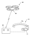
- FIG. 1 shows an embodiment of the present disclosure.
- the display device according to the present embodiment is, for example, an HMD 10 including a transmissive display unit 11, and displays a photographed image of a camera 80 mounted on a drone 90 that is a remotely operated mobile body and a small unmanned airplane. Displayed on the unit 11.
- the display device according to the present disclosure is not necessarily limited to the HMD illustrated in FIG.
- the display unit may not be a transmissive type as long as an image can be displayed.
- a drone flying in the air will be described as an example of the moving body, but the moving body may be any remotely operated drone such as a small helicopter or an airship.
- the moving body is not necessarily a flying body, for example, an unmanned vehicle that can travel in a dangerous environment where humans cannot approach, or a work robot equipped with a special undercarriage that can move even in complicated terrain such as rubble. Good. That is, it is not limited to a specific model as long as it is assumed that the viewer wearing the display device moves within a range that can be traced with eyes.
- the flight of the drone 90 is remotely controlled by the operation controller 30 by radio.
- the “user” of the HMD 10 refers to a person who wears the HMD 10 (or the display unit 11) on the head (hereinafter, referred to as “HMD wearer”).
- the operator is also an operator who controls the flight of the drone 90 by operating the operation controller 30.
- FIG. 2 is a circuit block diagram including the entire image display system according to the present embodiment.
- the drone 90 includes a microcomputer system in which a CPU 91, a ROM 92, and a RAM 93 are connected to an internal bus 99.
- a control command signal transmitted wirelessly from the operation controller 30 is received by the wireless connection IF 96.
- the CPU 91 analyzes the received control command signal, and the aircraft control unit 94 controls the flight of the drone 90 in accordance with the control command signal.
- the drone 90 is equipped with a GPS (Global Positioning System, hereinafter referred to as “GPS”) as the position information acquisition unit 95.
- GPS Global Positioning System
- the position information acquisition unit 95 may include an azimuth sensor such as an electronic compass that detects the orientation of the altimeter, the drone 90, or the camera 80 in addition to the GPS.
- the position information acquired by the position information acquisition unit 95 can include information on the three-dimensional position of the drone 90 and the orientation of the drone 90 or the camera 80.
- the position information of the drone 90 acquired by the position information acquisition unit 95 is transmitted to the operation controller 30 via the wireless connection IF 96.
- the camera 80 mounted on the drone 90 is controlled by the camera control unit 81.
- An image data signal of an image taken by the camera 80 is temporarily stored in the image RAM of the camera control unit 81 and transmitted to the operation controller 30 through the wireless connection IF 96 as needed.
- the camera control unit 81 may control the optical system of the camera 80 or the like under the control of the CPU 91 or in response to a zoom command signal transmitted from the operation controller 30.
- the optical mode of the camera 80 is divided into a standard mode, a wide-angle mode, and a zoom mode.
- the standard mode is a mode in which the lens is controlled at a focal position for photographing a predetermined range
- the wide-angle mode is a mode in which the focal position of the lens is controlled so as to photograph a wider range than the standard mode.
- the zoom mode is a mode in which the focal position of the lens is controlled so as to capture a range narrower than the standard mode.
- the camera control unit 81 can also perform digital zoom processing on an image captured by the camera 80.
- the wide-angle mode in the digital zoom processing is a mode in which an image captured by the camera 80 is output as it is, and the zoom mode is a part of the wide-angle mode image captured by the camera 80, which is enlarged and output.
- Means mode is a mode in which an image captured by the camera 80 is output as it is, and the zoom mode is a part of the wide-angle mode image captured by the camera 80, which is enlarged and output.
- the drone 90 is equipped with a battery 97 having a power supply capacity necessary for flight and a power supply circuit 98 for distributing power from the battery 97 to the flight drive unit, the camera 80 and various control units.
- the operation controller 30 includes an operation unit 32 that inputs operation information for remotely operating the drone 90.
- the operation unit 32 includes various operation switches such as a joystick and a push button provided in the casing of the operation controller 30.
- the operation controller 30 is a transmission / reception unit that transmits a control command signal or the like corresponding to the operation information input to the operation unit 32 to the drone 90 and receives position information from the drone 90, captured image data, and the like.
- a certain wireless connection IF 31 is provided.
- the position controller 45, the image generator 44, and a communication IF 46 that performs data communication with the HMD 10 are connected to the internal bus 49 of the operation controller 30.
- the CPU 41 functions as a display control unit that controls the display of the captured image from the camera 80 on the display unit 11 of the HMD 10 according to the present disclosure, in addition to the operation limiting unit of the drone 90. Note that the CPU 41 executes a program stored in the ROM 42, thereby realizing processing such as a relative position calculation unit, a visual field presence / absence determination unit, and a speed calculation unit, which will be described later.
- the position detector 45 is a GPS, for example, and detects the current position of the operation controller 30.
- the position detection unit 45 can be regarded as the position of the HMD 10 and the display unit 11.
- the image generation unit 44 performs processing such as generation, processing, and display mode switching of an image to be displayed on the display unit 11 under the control of the CPU 41. Specifically, as will be described later, an image that displays the relative position and direction of the drone 90 on the display unit 11, and a predetermined display that is displayed on the display unit 11 when the operator looks down to see another image, for example. An image can be generated.
- the image generation unit 44 can also perform digital zoom processing for reconstructing an image by enlarging or reducing the image.
- the image generation unit 44 may output the generated image data to the display unit 11 as an analog or digital video signal.
- the image generation unit may be provided in the HMD 10. In this case, under the control of the CPU 12, generation of an image to be displayed on the display unit 11, processing, switching of the display mode (digital zoom for switching to the wide-angle mode / zoom mode) (Including processing).
- the communication IF 46 is an interface for performing mutual information communication with the HMD 10 connected by wire or wireless.
- Image data captured by the camera 80 is transmitted from the operation controller 30 to the HMD 10.
- the data imaged by the image generation unit 44 is transmitted to the HMD 10 via the communication IF 46.
- the data includes, for example, numerical values, characters, direction / speed / distance markers, and the like.
- direction information detected by a direction detection unit 12 described later is output and received by the operation controller 30 via the communication IF 46.
- a battery 47 and a power supply circuit 48 for supplying power necessary for the operation of the operation controller 30 to the circuit are provided.
- the HMD 10 includes a microcomputer system in which a CPU 12, a ROM 13, a RAM 14, and a communication IF 16 are connected to an internal bus 19.
- a transmissive display unit 11 is also connected to the internal bus 19.
- An image data signal including a video signal transmitted from the CPU 12 and the operation controller 30 and received by the communication IF 16 is displayed on the display unit 11.
- the HMD 10 includes an orientation detection unit 15.
- the orientation detection unit 15 is preferably incorporated in, for example, the wearing tool 10a (see FIG. 1) in order to accurately detect the orientation of the head of the HMD wearer who is the operator of the drone 90.
- the direction detection unit 15 is preferably a sensor unit that combines an orientation sensor such as an electronic compass and a three-axis acceleration sensor. That is, it is possible to accurately detect the three-dimensional direction by detecting the direction in which the HMD 10 is directed by the azimuth sensor and taking into account the gravitational acceleration detected by the three-axis acceleration sensor.
- the HMD 10 is also provided with a battery 17 and a power supply circuit 18 for supplying power necessary for an image display operation to the circuit and the display unit 11.
- the display control means for controlling the image display on the HMD 10 is incorporated in the operation controller 30 of the drone 90 has been described.
- all or part of the system elements of the display device surrounded by the broken line 10 ′ in FIG. 2 may be separated from the operation controller 30.
- the main elements constituting the display control means such as the CPU 41, ROM 42, RAM 43, image generation unit 44, and position detection unit 45 are assigned to a dedicated CB (Control box, hereinafter referred to as “CB”) 20 shown in FIG. May be installed.
- CB Control box, hereinafter referred to as “CB”
- the display control means can be made into one chip by ASIC or the like, it may be incorporated in the display unit 11 of the HMD 10.
- the display control method described below is performed by arithmetic processing according to a control program stored in advance in the ROM 42 by the CPU 41.
- CPU41 detects the present position of the operation controller 30 by GPS which is the position detection part 45, for example (step S10).
- the CPU 41 acquires the position information of the drone 90 received from the wireless connection IF 31 (step S11).
- the relative position calculation unit of the CPU 41 calculates the relative position of the drone 90 with respect to the position of the operation controller 30 detected by the position detection unit 45 (step S12).
- the orientation detection unit 15 of the HMD 10 detects the orientation of the HMD 10.
- the detection value of the orientation detection unit 15 of the HMD 10 is output to the operation controller 30 as needed.
- CPU41 of the operation controller 30 acquires the orientation information of the said HMD10 based on the detected value from the orientation detection part 15 (step S13).
- the CPU 41 determines that the drone 90 is within a specific range based on the HMD 10 based on the relationship between the orientation of the HMD 10 acquired based on the detection value of the orientation detector 15 and the relative position of the drone 90 calculated by the relative position calculator. Determine if it exists.
- the “specific range” can be, for example, the field of view of the operator wearing the HMD 10.
- the field of view of the operator who is the HMD wearer is a solid angle set by applying a standard human viewing angle (for example, 120 degrees up and down, 200 degrees on the left and right) based on the position of the HMD 10. It can be a range.
- the in-view presence / absence determination unit of the CPU 41 determines whether the drone 90 exists in the view of the HMD wearer, that is, the operator (step S14).
- the CPU 41 turns off the display of the captured image from the drone 90 on the display unit 11 (step S14). S15).
- the CPU 41 turns on the display of the photographed image on the display unit 11. Even when the drone 90 is out of the operator's field of view, if the operator inputs an operation for turning on image display to the operation controller 30 or the CB 20, a captured image is displayed on the display unit 11. Also good.
- the CPU 41 When the visual field presence / absence determining unit determines that the drone 90 does not exist in the operator's visual field, and the direction of the HMD 10 detected by the direction detecting unit 15 is a specific direction (step S16: Yes), the CPU 41 The display on the display unit 11 is switched to a predetermined image (step S17).
- the “specific orientation” corresponds to, for example, a case where the operator tries to look at an image other than the drone 90, such as turning the line of sight toward the operation controller 30 at hand. In such a case, for example, by displaying predetermined images such as a help menu, a setting menu, and a manual guide on the display unit 11, the convenience for the operator can be improved.
- the CPU 41 displays information on the direction of the drone 90 based on the orientation of the HMD 10 and the relative position of the drone 90. 11 is displayed as a guide (step S18).
- an arrow indicates the direction in which the drone 90 exists based on the current position of the HMD 10, plotting the position of the drone 90 on the simulated radar screen, and the relative position of the drone It may be displayed with numerical values, characters, markers, etc. Further, information that assists in searching for the drone 90 such as the distance to the drone 90 and the speed may be displayed together with the information related to the direction.
- the drone 90 can be quickly and easily found even when the eye is away from the drone 90, and visual tracking can be resumed.
- the CPU 41 may restrict the operation of the operation unit 32 of the operation controller 30 that performs remote operation of the drone 90 during a period when the drone 90 does not exist in the operator's field of view (step S19). At this time, the CPU 41 may output a control command signal for stopping and hovering the drone 90 on the spot to the drone 90.
- the drone 90 when the drone 90 is out of the operator's field of view, the drone 90 may cause an accident due to an erroneous operation by the operator, or may move to an unexpected place and become uncontrollable. The situation can be prevented.
- step S14 when the visual field presence / absence determining unit determines that the drone 90 exists in the operator's visual field (step S14: Yes), the speed calculation unit of the CPU 41 is based on the position information of the drone 90 received from the wireless connection IF 31. Then, the speed V of the drone 90 is calculated (step S20). Then, when the calculated speed V of the drone 90 is equal to or higher than the predetermined speed V1 (V ⁇ V1) (step S22: Yes), the CPU 41 turns off the display of the captured image on the display unit 11 (step S15). ).
- the speed V of the drone 90 when the drone 90 is moved to a target location at high speed, the operator performs a remote operation while watching the drone 90. For this reason, it is not necessary to display captured images on the display unit 11, but rather these images may interfere with the operation.
- the speed V of the drone 90 when the speed V of the drone 90 is higher than the predetermined speed V1, the display of the captured image is turned off, thereby ensuring the visibility when the operator tracks the drone 90 with eyes. Increases sex.
- the speed V of the drone 90 may be a speed in the horizontal direction component or a speed in the height direction component.
- the speed V of the drone 90 may be a speed obtained by combining the horizontal direction component and the height direction component.
- step S23 when the speed V of the drone 90 is slower than the predetermined speed V1 (step S22: No), the CPU 41 switches the captured image on the display unit 11 to the wide angle mode (step S23).
- the wide-angle mode image data of a size captured by the camera 80 is output to the display unit 11 as it is, and a captured image in a range wider than a predetermined range is displayed.
- the CPU 41 may transmit a command signal to the drone 90 to control the optical system of the camera 80 to the wide angle mode.
- the drone 90 when the drone 90 is moving at a speed lower than a certain speed, the drone 90 is often located around the destination to be photographed. Therefore, by automatically switching to the wide-angle mode, it is possible to catch the rough position of the object to be photographed, and the convenience for the operator is improved.
- step S24 when the speed V of the drone 90 is equal to or lower than the stop determination speed V2 (V2 ⁇ V1) at which the CPU 41 is determined to be substantially stopped (step S24: Yes), the CPU 41 changes the display mode of the display unit 11 to the zoom mode. (Step S25). In the zoom mode, the CPU 41 cuts out a part of the image captured by the camera 80 and causes the display unit 11 to display an enlarged image in a range narrower than a predetermined range. Note that the CPU 41 may transmit a command signal to the drone 90 to control the optical system of the camera 80 to the zoom mode.
- the drone 90 when the drone 90 is at or below the stop determination speed V2, that is, when it is almost stopped, the drone 90 often reaches the destination to be photographed. Therefore, by automatically switching to the zoom mode, the details of the object to be photographed can be captured, and the convenience for the operator is improved.
Abstract
移動体からの撮影画像を表示する表示装置または表示制御方法において、操作者が画像に混乱することなく移動体を視認できる等の利便性を高めること。表示装置(HMD)10は、移動体(ドローン)90に搭載したカメラ80が撮影した画像を表示部11に表示させる。移動体90を制御する操作コントローラ30は、移動体90から送信される情報を受信する受信部31と、表示装置10の位置を検出する位置検出部45とを備える。表示制御手段41は、表示装置10に対する移動体90の相対位置に応じた情報を表示部11に表示する。例えば、表示制御手段41は、操作者の視界に移動体90がないと判断したとき表示部11への撮影画像の表示をOFFにする。
Description
本開示は、画像を表示可能な例えばヘッドマウントディスプレイ等の表示装置および表示装置を用いた表示制御方法に関する。
近年、例えば小型の無人飛行機であるドローンなど無線で遠隔操作される移動体にカメラを搭載し、カメラで撮影した画像をリアルタイムで地上のディスプレイに表示することが行われている。このようなディスプレイを、移動体を操作する操作コントローラに設けた場合、操作者は、飛行する移動体を見ているとディスプレイに表示される画像を確認できず、他方、ディスプレイを見ていると移動体を見ることができない。このように操作者は、移動体と撮影画像とを同時には視認できないため、操作ミスによる事故の危険性や移動体を何処かに見失ってしまう等の恐れがある。
カメラで撮影した画像と外界の実景とを同時に表示できる技術に関しては、従来、透過型(シースルー)の表示装置が知られている。例えば特許文献1の表示操作部メガネは、角度センサと視点センサとを内蔵し、これらのセンサにより検出される観者の視線の向きに合わせて表示するカメラの向きが制御される。また視点センサにより検知される観者の目の焦点距離に応じてカメラの電動ズームレンズの焦点も制御される。
また、例えば特許文献2には、車両の周囲に設けた複数台のカメラからの画像を切り換えて外界の景色に重ねて表示可能なHMD(Head Mounted Display、以下、「HMD」という)が開示されている。HMDは、それを装着する運転者の頭部の向きを検出する検出部を備え、検出部の検出結果つまり運転者の視線方向に応じて車両の死角を写すカメラが選択される。
しかし、ドローンのように位置が常時変化する移動体からの撮影画像は、移動体が操作者の視界から外れたときに操作者に混乱を招く場合がある。また、操作者の誤操作により移動体が事故を引き起こし、または移動体が予期しない場所に移動して制御不能に陥る危険性も否定できない。
本開示は、こうした事情に鑑みてなされたものであり、移動体で撮影された画像を表示部に表示する表示装置または表示制御方法において、操作者が撮影画像に混乱することなく移動体を視認できること、または仮に移動体を見失ったとしても容易に発見できる等の利便性を高めた技術を提供することを目的としている。
上述した課題を解決するため、本開示は、遠隔操作される移動体に搭載されたカメラで撮影される画像を表示可能な表示装置であって、使用者の頭部に装着可能であって画像を表示可能な表示部と、前記表示部における画像表示を制御する表示制御手段と、移動体から送信されてくる撮影画像および移動体の位置情報を受信する受信部と、当該表示装置の位置を検出する位置検出部とを備え、前記表示制御手段は、前記位置検出部より検出された当該表示装置の位置に対する、前記受信部より受信した前記移動体の位置情報に基づく相対位置に応じた情報を前記表示部に表示可能な表示装置である。
この構成の表示装置によれば、移動体の相対位置に応じた情報を表示部に表示することにより、操作者は移動体の位置を容易に知ることができる。また表示部が表示する画像に操作者が混乱しないようにすることができる。
上記構成の表示装置において、前記表示部の向きを検出する向き検出部と、前記向き検出部より検出される当該表示部の向き、および前記位置検出部より検出される当該表示部の位置に対する特定の範囲内に前記移動体が存在するか否かを判断する判断部を備え、前記表示制御手段は、前記移動体が前記特定の範囲内に存在するか否かに応じて、前記表示部へ表示する画像を切り換えることが好ましい。
この構成の表示装置によれば、移動体が特定の範囲内に存在するか否かに応じて表示部への表示を切り換えるので、操作者が移動体を操作中に不要な画像が表示されて操作者が混乱しないようにすることができる。
また、上記構成の表示装置において、前記判断部が前記特定の範囲内に移動体が存在しないと判断したとき、前記表示制御手段は前記表示部への前記撮影画像の表示をOFFにすることが好ましい。
この構成の表示装置によれば、移動体が特定の範囲内に存在しない場合に撮像画像を表示しないので、操作者を混乱させないようにし、誤操作を防ぐことができる。また、特定の範囲内に存在しない移動体を探す際に、撮影画像が邪魔になることもない。
また、上記構成の表示装置において、前記判断部が前記特定の範囲内に移動体が存在しないと判断し、かつ、前記表示部の向きが特定向きであるとき、前記表示制御手段は前記表示部への表示を所定の画像に切り換えることが好ましい。
この構成の表示装置によれば、操作者が例えば移動体から目を離して他の画像を見ようとした場合に所定の画像に切り換わるので、操作者の利便性を高めることができる。
また、上記構成の表示装置において、前記判断部が前記特定の範囲内に移動体が存在しないと判断したとき、前記表示制御手段は、前記表示部の向きと前記移動体の相対位置とに基づいて、当該移動体の方向に関する情報を前記表示部に表示することが好ましい。
この構成の表示装置によれば、操作者が仮に移動体を見失ったとしても移動体の方向に関する情報が表示されるので、移動体の発見を容易にし、利便性を高めることができる。
また、上記構成の表示装置において、前記特定の範囲内に移動体が存在しないとき、移動体に対する遠隔操作を行うための操作情報を入力する操作部の操作を制限する操作制限手段を備えることが好ましい。
この構成の表示装置によれば、例えば操作者の視界の外に移動体が存在する場合に、操作者が誤って操作部を操作することにより、移動体が予期せぬ方向や場所に移動してしまうのを防ぐことができる。
また、上記構成の表示装置において、前記受信部より受信した前記移動体の位置情報に基づいて当該移動体の速度を演算する速度演算部を備え、前記速度演算部より演算された移動体の速度が所定の速度以上であるとき、前記表示制御手段は前記表示部への前記撮影画像の表示をOFFにすることが好ましい。
この構成の表示装置によれば、例えば移動体を目的値にまで高速で移動させる際に撮影画像の表示を自動的にOFFにすることにより、移動体を操作中の操作者の視認性を確保し、利便性を高めることができる。
また、上記構成の表示装置において、前記受信部より受信した前記移動体の位置情報に基づいて当該移動体の速度を演算する速度演算部を備え、前記表示制御手段は、前記特定の範囲内に移動体が存在すれば前記撮影画像の表示をONにするとともに、前記速度演算部より演算された移動体の速度が所定の速度よりも遅いと判断したとき、所定範囲よりも広い範囲の撮影画像を表示する広角モードに切り換えることが好ましい。
この構成の表示装置によれば、例えば移動体が目的地に近づいたときには速度を遅くし、広角モードで撮影対象物の大まかな位置をとらえることができるので、利便性を高めることができる。
また、上記構成の表示装置において、前記表示制御手段は、前記速度演算部より演算された移動体の速度が、前記所定の速度よりも遅い停止判断速度以下であるとき、所定範囲よりも狭い範囲の撮影画像を表示するズームモードに切り換えることが好ましい。
この構成の表示装置によれば、例えば移動体が目的地に到着し停止したときにはズームモードで撮影対象物の詳細をとらえることができるので、利便性を高めることができる。
また、本開示は、遠隔操作される移動体に搭載されたカメラで撮影される画像を、使用者の頭部に装着可能な表示部に表示する表示制御方法であって、移動体から送信されてくる撮影画像および移動体の位置情報を受信部より受信するステップと、位置検出部より当該表示装置の位置を検出するステップと、前記位置検出部より検出された当該表示装置の位置に対する、前記受信部より受信した前記移動体の位置情報に基づく相対位置を演算するステップと、演算した相対位置に応じた情報を前記表示部に表示するステップとを含む表示制御方法である。
この表示制御方法によれば、移動体の相対位置に応じた情報を表示部に表示することにより、操作者は移動体の位置を容易に知ることができる。また表示部が表示する画像に操作者が混乱しないようにすることができる。
上記表示制御方法において、向き検出部より前記表示部の向きを検出するステップと、前記向き検出部より検出される当該表示部の向き、および前記位置検出部より検出される当該表示部の位置に対する特定の範囲内に前記移動体が存在するか否かを判断するステップと、前記特定の範囲内に前記移動体が存在するか否かに応じて前記表示部へ表示する画像を切り換えるステップとを含むことが好ましい。
この表示制御方法によれば、移動体が特定の範囲内に存在するか否かに応じて表示部への表示を切り換えるので、操作者が移動体を操作中に不要な画像が表示されて操作者が混乱しないようにすることができる。
また、上記表示制御方法において、前記特定の範囲内に移動体が存在しないと判断したとき、前記表示部への前記撮影画像の表示をOFFにするステップを含むことが好ましい。
この表示制御方法によれば、移動体が特定の範囲内に存在しない場合に撮像画像を表示しないので、操作者を混乱させないようにし、誤操作を防ぐことができる。また、特定の範囲内に存在しない移動体を探す際に、撮影画像が邪魔になることもない。
また、上記表示制御方法において、前記特定の範囲内に移動体が存在しないと判断し、かつ、前記表示部の向きが特定向きであるとき、前記表示部への表示を所定の画像に切り換えるステップを含むことが好ましい。
この表示制御方法によれば、操作者が例えば移動体から目を離して他の画像を見ようとした場合に所定の画像に切り換わるので、操作者の利便性を高めることができる。
また、上記表示制御方法において、前記特定の範囲内に移動体が存在しないと判断したとき、前記表示部の向きと前記移動体の相対位置とに基づいて、当該移動体の方向に関する情報を前記表示部に表示するステップを含むことが好ましい。
この表示制御方法によれば、操作者が仮に移動体を見失ったとしても移動体の方向に関する情報が表示されるので、移動体の発見を容易にし、利便性を高めることができる。
また、上記表示制御方法において、前記特定の範囲内に移動体が存在しないとき、移動体に対する遠隔操作を行うための操作情報を入力する操作部の操作を制限するステップを含むことが好ましい。
この表示制御方法によれば、例えば操作者の視界の外に移動体が存在する場合に、操作者が誤って操作部を操作することにより、移動体が予期せぬ方向や場所に移動してしまうのを防ぐことができる。
また、上記表示制御方法において、前記受信部より受信した前記移動体の位置情報に基づいて当該移動体の速度を演算するステップと、演算された移動体の速度が所定の速度以上であるとき、前記表示部への前記撮影画像の表示をOFFにするステップを含むことが好ましい。
この表示制御方法によれば、例えば移動体を目的値にまで高速で移動させる際に撮影画像の表示を自動的にOFFにすることにより、移動体を操作中の操作者の視認性を確保し、利便性を高めることができる。
また、上記表示制御方法において、前記受信部より受信した前記移動体の位置情報に基づいて当該移動体の速度を演算するステップと、前記特定の範囲内に移動体が存在すると判断したとき前記表示部への前記撮影画像の表示をONにするステップと、演算された移動体の速度が所定の速度よりも遅いと判断したとき、所定範囲よりも広い範囲の撮影画像を表示する広角モードに切り換えるステップとを含むことが好ましい。
この表示制御方法によれば、例えば移動体が目的地に近づいたときには速度を遅くし、広角モードで撮影対象物の大まかな位置をとらえることができるので、利便性を高めることができる。
また、上記表示制御方法において、演算された移動体の速度が、前記所定の速度よりも遅い停止判断速度以下であるとき、所定範囲よりも狭い範囲の撮影画像を表示するズームモードに切り換えるステップを含むことが好ましい。
この表示制御方法によれば、例えば移動体が目的地に到着し停止したときにはズームモードで撮影対象物の詳細をとらえることができるので、利便性を高めることができる。
本開示によれば、移動体の操作者が撮影画像に混乱することなく移動体の位置を確実に視認することができる。また、仮に移動体を見失ったとしても容易に移動体を発見することができる。これらにより、利便性の高い表示装置および表示制御方法を提供することができる。
図1に本開示の一実施態様を示す。本実施形態の表示装置は、例えば透過型の表示部11を備えるHMD10であって、遠隔操作される移動体であって小型の無人飛行機である ドローン90に搭載されたカメラ80の撮影画像が表示部11に表示される。ただし、本開示に係る表示装置は、必ずしも図1に示すHMDに限定されるものではない。また、表示部は、画像が表示可能であれば透過型でなくてもよい。また、ここでは、移動体の例として空中を飛行するドローンを挙げて説明するが、移動体は、例えば小型ヘリコプターまたは飛行船などの遠隔操作される任意の無人機であってもよい。また、移動体は、必ずしも飛行体でなくても、例えば人が近づけない危険な環境で走行可能な無人車両や、瓦礫などの複雑な地形でも移動できる特殊な足回りを備えた作業ロボットなどでもよい。つまり、表示装置を装着する観者が目で追跡可能な範囲で移動することが想定される移動体であれば、特定の機種に限定されない。
図1に示す実施形態において、ドローン90は、操作コントローラ30により、その飛行が無線で遠隔操作される。ここで、HMD10の「使用者」とは、HMD10(または表示部11)を頭部に装着する者(以下、「HMD装着者」という。)をいうが、本実施形態ではその使用者自身が、操作コントローラ30を操作してドローン90の飛行をコントロールする操作者でもある。
図2は、本実施形態による画像表示システムの全体を含む回路ブロック図である。
先ず、ドローン90の構成について説明する。ドローン90には、CPU91、ROM92およびRAM93が内部バス99に接続されたマイクロコンピュータシステムが内部に構成されている。操作コントローラ30から無線で送信される制御指令信号は、無線接続IF96により受信される。受信した制御指令信号をCPU91が解析し、その制御指令信号に従って機体制御部94によりドローン90の飛行が制御される。
先ず、ドローン90の構成について説明する。ドローン90には、CPU91、ROM92およびRAM93が内部バス99に接続されたマイクロコンピュータシステムが内部に構成されている。操作コントローラ30から無線で送信される制御指令信号は、無線接続IF96により受信される。受信した制御指令信号をCPU91が解析し、その制御指令信号に従って機体制御部94によりドローン90の飛行が制御される。
ドローン90は、位置情報取得部95としてGPS(Global Positioning System、以下、「GPS」という)を搭載している。位置情報取得部95は、GPSに加えて、高度計やドローン90またはカメラ80の向きを検出する電子コンパスなどの方位センサを含むものでもよい。位置情報取得部95により取得される位置情報は、ドローン90の三次元位置およびドローン90またはカメラ80の向きの情報を含むことができる。位置情報取得部95により取得されたドローン90の位置情報は、無線接続IF96を介して操作コントローラ30に送信される。
ドローン90に搭載されるカメラ80は、カメラ制御部81により制御される。カメラ80で撮影された画像の画像データ信号は、一旦、カメラ制御部81の画像RAMに格納され、無線接続IF96を介して操作コントローラ30に随時送信される。
また、カメラ制御部81は、CPU91の制御下で、または操作コントローラ30から送信されるズーム指令信号に応じて、カメラ80の光学系等を制御してもよい。ここで、カメラ80の光学モードは、標準モード、広角モードおよびズームモードに分けられる。標準モードが所定範囲を撮影する焦点位置にレンズが制御されたモードであるとした場合、広角モードは、標準モードよりも広い範囲を撮影するようにレンズの焦点位置が制御されたモードである。また、ズームモードは、標準モードよりも狭い範囲を撮影するようにレンズの焦点位置が制御されたモードである。
また、カメラ制御部81は、カメラ80が撮影した画像をデジタルズーム処理することもできる。この場合、デジタルズーム処理における広角モードとは、カメラ80が撮影した画像をそのまま出力するモードであり、ズームモードとは、カメラ80が撮影した広角モードの画像の一部を切り出し、拡大して出力するモードを意味する。
また、カメラ制御部81は、カメラ80が撮影した画像をデジタルズーム処理することもできる。この場合、デジタルズーム処理における広角モードとは、カメラ80が撮影した画像をそのまま出力するモードであり、ズームモードとは、カメラ80が撮影した広角モードの画像の一部を切り出し、拡大して出力するモードを意味する。
これらの他、ドローン90は、飛行に必要な電源容量のバッテリ97およびバッテリ97からの電力を飛行駆動部、カメラ80および各種制御部に配電する電源回路98を搭載している。
次に、操作コントローラ30の構成を説明する。操作コントローラ30は、ドローン90の遠隔操作を行うための操作情報を入力する操作部32を備えている。操作部32は、具体的には操作コントローラ30の筐体に設けたジョイスティック、押しボタン等の各種操作スイッチ類により構成される。また、操作コントローラ30には、操作部32に入力された操作情報に応じた制御指令信号等をドローン90に対して送信し、ドローン90からの位置情報や撮影画像データ等を受信する送受信部である無線接続IF31が備えられている。
操作コントローラ30の内部バス49には、CPU41、ROM42、RAM43の他に、位置検出部45、画像生成部44、およびHMD10とのデータ通信を行う通信IF46などが接続されている。
CPU41は、ドローン90の操作制限手段である他に、本開示に係るHMD10の表示部11にカメラ80からの撮影画像を表示する制御を行う表示制御手段としても機能する。なお、CPU41がROM42に記憶されるプログラムを実行することで、後述する相対位置演算部、視界内有無判断部、速度演算部等の処理が実現される。
位置検出部45は、例えばGPSであり、操作コントローラ30の現在位置を検出する。本実施形態では、HMD装着者が操作コントローラ30を操作してドローン90をコントロールすることから、HMD10と操作コントローラ30との距離は非常に近い。そのため、位置検出部45により検出した操作コントローラ30の位置を、HMD10および表示部11の位置とみなすことができる。
画像生成部44は、CPU41の制御下で、表示部11に表示させる画像の生成、加工、表示モードの切り換え等の処理を行う。具体的には、後述するように、ドローン90の相対位置や方向を表示部11に表示させる画像や、操作者が例えば他の画像を見ようと下を向いた時に表示部11に表示させる所定の画像を生成することができる。また、画像生成部44は、画像を拡大または縮小して再構成するデジタルズーム処理を行うこともできる。画像生成部44は、生成した画像データをアナログまたはデジタルのビデオ信号として表示部11に出力するものでもよい。なお、画像生成部はHMD10内に設けられていてもよく、この場合はCPU12の制御下で、表示部11に表示させる画像の生成、加工、表示モードの切り換え(広角モード/ズームモードに切り換えるデジタルズーム処理を含む)等の処理を行ってもよい。
通信IF46は、有線または無線により接続されるHMD10との間の相互の情報通信を行うインタフェースである。操作コントローラ30からHMD10へは、カメラ80で撮影された撮影データが送信される。また、ドローン90から送信された移動体位置情報に基づいて、画像生成部44により画像化されたデータなどが、通信IF46を介してHMD10に送信される。なおデータは、例えば数値、文字、方位・速度・距離マーカ等を含む。
他方、HMD10からは、後述する向き検出部12で検出される向きの情報が出力され、通信IF46を介して操作コントローラ30に受信される。
他方、HMD10からは、後述する向き検出部12で検出される向きの情報が出力され、通信IF46を介して操作コントローラ30に受信される。
これらの他に、操作コントローラ30の動作に必要な電力を回路に供給するバッテリ47および電源回路48が設けられている。
次に、HMD10の構成を説明する。HMD10には、CPU12、ROM13、RAM14および通信IF16が内部バス19に接続されたマイクロコンピュータシステムが搭載されている。内部バス19にはまた、透過型の表示部11が接続されている。CPU12、操作コントローラ30から送信され、通信IF16により受信したビデオ信号を含む画像データ信号を表示部11に表示させる。
HMD10には、向き検出部15が備えられている。向き検出部15は、ドローン90の操作者であるHMD装着者の頭の向きを的確に検出するため、例えば装着具10a(図1参照)に内蔵されることが好ましい。向き検出部15は、例えば電子コンパスなどの方位センサと3軸加速度センサを組み合わせたセンサユニットであることが好ましい。つまり、方位センサによりHMD10が向いている方角を検出し、3軸加速度センサにより検出される重力加速度をそれに加味することで、三次元の向きを正確に検出することができる。
HMD10にはまた、画像の表示動作に必要な電力を回路や表示部11に供給するバッテリ17および電源回路18が設けられている。
なお、ここでは、HMD10への画像表示を制御する表示制御手段が、ドローン90の操作コントローラ30に組み込まれた実施形態を説明した。その他の態様として、図2の破線10’で囲む表示装置のシステム要素の全部または一部を、操作コントローラ30から分離して構成してもよい。例えば、CPU41、ROM42、RAM43、画像生成部44、位置検出部45などの表示制御手段を構成する主要な要素を、例えば図3に示す専用のCB(Control box、以下「CB」という)20に搭載してもよい。更には、表示制御手段をASIC等によりワンチップ化できれば、HMD10の表示部11にそれを組み込んでもよい。
次に、図4のフローチャートを参照して、表示制御手段による表示制御方法を説明する。なお、以下説明する表示制御方法は、CPU41がROM42に予め記憶された制御プログラムに従って演算処理により行われる。
CPU41は、位置検出部45である例えばGPSにより、操作コントローラ30の現在の位置を検出する(ステップS10)。
続いてCPU41は、無線接続IF31より受信したドローン90の位置情報を取得する(ステップS11)。
CPU41の相対位置演算部は、位置検出部45より検出された操作コントローラ30の位置に対するドローン90の相対位置を演算する(ステップS12)。
HMD10の向き検出部15は、HMD10の向きを検出する。HMD10の向き検出部15の検出値は、操作コントローラ30に随時出力されている。これにより、操作コントローラ30のCPU41は、向き検出部15からの検出値に基づいて、当該HMD10の向き情報を取得する(ステップS13)。
CPU41は、向き検出部15の検出値に基づいて取得したHMD10の向きと、相対位置演算部が演算したドローン90の相対位置との関係から、HMD10を基準にした特定の範囲内にドローン90が存在するか否か判断する。ここで、「特定の範囲」とは、例えばHMD10を装着する操作者の視界とすることができる。この場合のHMD装着者である操作者の視界の範囲は、HMD10の位置を基点に、標準的な人の視野角(例えば上下120度、左右200度など)を当てはめて設定される立体角の範囲とすることができる。
本実施形態では、CPU41の視界内有無判断部が、HMD装着者、つまり操作者の視界内にドローン90が存在するか判断する(ステップS14)。視界内有無判断部が、操作者の視界内にドローン90が存在しないと判断すると(ステップS14:No)、CPU41は、ドローン90からの撮影画像の表示部11への表示をOFFにする(ステップS15)。
このように、ドローン90が視界から外れたときに撮影画像をOFFにすることで、操作者に混乱を生じさせないようにすることができ、またドローン90への操作ミスを防ぐことができる。また、ドローン90を探す際に、撮影画像が邪魔になることもない。
なお、フローチャートには示していないが、操作者の視界内にドローン90が戻った時点で、CPU41は、撮影画像の表示部11への表示をONにする。また、ドローン90が操作者の視界から外れた期間であっても、操作者が操作コントローラ30またはCB20に画像表示ONの操作入力を行った場合には、表示部11に撮影画像を表示してもよい。
視界内有無判断部が操作者の視界内にドローン90が存在しないと判断し、かつ、向き検出部15より検出されたHMD10の向きが特定向きであるとき(ステップS16:Yes)、CPU41は、表示部11への表示を所定の画像に切り換える(ステップS17)。
ここで、「特定向き」であるときとは、例えば、操作者が手元の操作コントローラ30に視線を向けるなど、ドローン90以外の他の画像を見ようとする場合などが相当する。そのような場合には、例えばヘルプメニュー、設定メニュー、マニュアルガイドなどの所定の画像を表示部11に表示することで、操作者の利便性を高めることができる。
ここで、「特定向き」であるときとは、例えば、操作者が手元の操作コントローラ30に視線を向けるなど、ドローン90以外の他の画像を見ようとする場合などが相当する。そのような場合には、例えばヘルプメニュー、設定メニュー、マニュアルガイドなどの所定の画像を表示部11に表示することで、操作者の利便性を高めることができる。
また、視界内有無判断部が操作者の視界内にドローン90が存在しないと判断したとき、CPU41は、HMD10の向きとドローン90の相対位置とに基づいて、ドローン90の方向に関する情報を表示部11にガイド表示する(ステップS18)。ドローン90の方向に関する情報を表示する態様としては、HMD10の現在位置を基準としてドローン90が存在する方向を矢印で示すこと、模擬レーダー画面にドローン90の位置をプロットすること、ドローンの相対位置を数値、文字、マーカ等で表示することなどがある。また、ドローン90までの距離や速度など、ドローン90を探すために補助となる情報も、方向に関する情報に併せて表示してもよい。
このように、ドローン90の方向に関する情報を表示することで、ドローン90から目を離した場合でも迅速かつ容易にドローン90を発見することができ、目視による追跡を再開させることができる。
更に、CPU41は、操作者の視界内にドローン90が存在しない期間、ドローン90の遠隔操作を行う操作コントローラ30の操作部32の操作を制限してもよい(ステップS19)。また、このときCPU41は、ドローン90をその場で停止させホバリングさせる制御指令信号をドローン90に対して出力してもよい。
このような操作制限処理を設けることにより、操作者の視界からドローン90が外れた場合に、操作者の誤操作によりドローン90が事故を起こしたり、予期しない場所へ移動して制御不能となるような事態を防ぐことができる。
一方、視界内有無判断部が操作者の視界内にドローン90が存在すると判断したとき(ステップS14:Yes)、CPU41の速度演算部は、無線接続IF31より受信したドローン90の位置情報に基づいて、ドローン90の速度Vを演算する(ステップS20)。そして、演算されたドローン90の速度Vが所定の速度V1以上(V≧V1)であるとき(ステップS22:Yes)、CPU41は、表示部11への撮影画像の表示をOFFにする(ステップS15)。
例えば、ドローン90を目的の場所まで高速で移動させる場合には、操作者はドローン90を注視しながら遠隔操作する。そのため、表示部11には撮像画像を表示する必要がなく、むしろこれらの画像が操作の邪魔になる場合もある。本実施形態では、ドローン90の速度Vが所定の速度V1以上に速いときに撮影画像の表示をOFFにすることにより、操作者がドローン90を目で追跡する際の視認性を確保し、利便性を高めている。なお、ドローン90の速度Vは水平方向成分における速度でもよく、高さ方向成分における速度を用いてもよい。また、ドローン90の速度Vは水平方向成分と高さ方向成分を合成した速度を用いてもよい。
次に、CPU41は、ドローン90の速度Vが所定の速度V1よりも遅いとき(ステップS22:No)、CPU41は、表示部11への撮影画像を広角モードに切り換える(ステップS23)。広角モードでは、カメラ80が撮影したサイズの画像データが表示部11にそのまま出力され、所定範囲よりも広い範囲の撮影画像が表示される。なお、CPU41は、ドローン90に指令信号を送信して、カメラ80の光学系を広角モードに制御してもよい。
例えば、ドローン90がある速度未満のスピードで移動しているときには、撮影すべき目的地周辺にドローン90が位置している場合が多い。そのため、自動的に広角モードに切り換えることにより、撮影対象物の大まかな位置をとらえることができ、操作者の利便性が向上する。
更に、CPU41は、ドローン90の速度Vがほぼ停止と判断される停止判断速度V2(V2<<V1)以下であるとき(ステップS24:Yes)、CPU41は、表示部11の表示モードをズームモードに切り換える(ステップS25)。ズームモードでは、CPU41は、カメラ80が撮影した画像の一部を切り出し、所定範囲よりも狭い範囲の拡大した画像を表示部11に表示させる。なお、CPU41は、ドローン90に指令信号を送信し、カメラ80の光学系をズームモードに制御してもよい。
例えば、ドローン90が停止判断速度V2以下、つまりほぼ停止しているときは、撮影すべき目的地にドローン90が到達している場合が多い。そのため、自動的にズームモードに切り換えることにより、撮影対象物の詳細をとらえることができ、操作者の利便性が向上する。
10、10’ HMD(ヘッドマウントディスプレイ)
10a 装着具
11 表示部
12 向き検出部
16 通信IF
20 CB(コントロールボックス)
30 操作ボックス
31 無線接続IF
32 操作部
41 CPU
44 画像生成部
45 位置検出部
46 通信IF
80 カメラ
90 ドローン(移動体)
96 無線接続IF
10a 装着具
11 表示部
12 向き検出部
16 通信IF
20 CB(コントロールボックス)
30 操作ボックス
31 無線接続IF
32 操作部
41 CPU
44 画像生成部
45 位置検出部
46 通信IF
80 カメラ
90 ドローン(移動体)
96 無線接続IF
Claims (18)
- 遠隔操作される移動体に搭載されたカメラで撮影される画像を表示可能な表示装置であって、
使用者の頭部に装着可能であって画像を表示可能な表示部と、
前記表示部における画像表示を制御する表示制御手段と、
移動体から送信されてくる撮影画像および移動体の位置情報を受信する受信部と、
当該表示装置の位置を検出する位置検出部とを備え、
前記表示制御手段は、前記位置検出部より検出された当該表示装置の位置に対する、前記受信部より受信した前記移動体の位置情報に基づく相対位置に応じた情報を前記表示部に表示可能な表示装置。 - 前記表示部の向きを検出する向き検出部と、
前記向き検出部より検出される当該表示部の向き、および前記位置検出部より検出される当該表示部の位置に対する特定の範囲内に前記移動体が存在するか否かを判断する判断部を備え、
前記表示制御手段は、前記移動体が前記特定の範囲内に存在するか否かに応じて、前記表示部へ表示する画像を切り換える、請求項1に記載の表示装置。 - 前記判断部が前記特定の範囲内に移動体が存在しないと判断したとき、前記表示制御手段は前記表示部への前記撮影画像の表示をOFFにする、請求項2に記載の表示装置。
- 前記判断部が前記特定の範囲内に移動体が存在しないと判断し、かつ、前記表示部の向きが特定向きであるとき、前記表示制御手段は前記表示部への表示を所定の画像に切り換える、請求項2に記載の表示装置。
- 前記判断部が前記特定の範囲内に移動体が存在しないと判断したとき、前記表示制御手段は、前記表示部の向きと前記移動体の相対位置とに基づいて、当該移動体の方向に関する情報を前記表示部に表示する、請求項2に記載の表示装置。
- 前記特定の範囲内に移動体が存在しないとき、移動体に対する遠隔操作を行うための操作情報を入力する操作部の操作を制限する操作制限手段を備える、請求項2~5の何れか1項に記載の表示装置。
- 前記受信部より受信した前記移動体の位置情報に基づいて当該移動体の速度を演算する速度演算部を備え、
前記速度演算部より演算された移動体の速度が所定の速度以上であるとき、前記表示制御手段は前記表示部への前記撮影画像の表示をOFFにする、請求項1~6の何れか1項に記載の表示装置。 - 前記受信部より受信した前記移動体の位置情報に基づいて当該移動体の速度を演算する速度演算部を備え、
前記表示制御手段は、前記特定の範囲内に移動体が存在すれば前記撮影画像の表示をONにするとともに、前記速度演算部より演算された移動体の速度が所定の速度よりも遅いと判断したとき、所定範囲よりも広い範囲の撮影画像を表示する広角モードに切り換える、請求項1~6の何れか1項に記載の表示装置。 - 前記表示制御手段は、前記速度演算部より演算された移動体の速度が、前記所定の速度よりも遅い停止判断速度以下であるとき、所定範囲よりも狭い範囲の撮影画像を表示するズームモードに切り換える、請求項8に記載の表示装置。
- 遠隔操作される移動体に搭載されたカメラで撮影される画像を、使用者の頭部に装着可能な表示部に表示する表示制御方法であって、
移動体から送信されてくる撮影画像および移動体の位置情報を受信部より受信するステップと、
位置検出部より当該表示装置の位置を検出するステップと、
前記位置検出部より検出された当該表示装置の位置に対する、前記受信部より受信した前記移動体の位置情報に基づく相対位置を演算するステップと、
演算した相対位置に応じた情報を前記表示部に表示するステップと
を含む表示制御方法。 - 向き検出部より前記表示部の向きを検出するステップと、
前記向き検出部より検出される当該表示部の向き、および前記位置検出部より検出される当該表示部の位置に対する特定の範囲内に前記移動体が存在するか否かを判断するステップと、
前記特定の範囲内に前記移動体が存在するか否かに応じて前記表示部へ表示する画像を切り換えるステップと
を含む、請求項10に記載の表示制御方法。 - 前記特定の範囲内に移動体が存在しないと判断したとき、前記表示部への前記撮影画像の表示をOFFにするステップを含む、請求項11に記載の表示制御方法。
- 前記特定の範囲内に移動体が存在しないと判断し、かつ、前記表示部の向きが特定向きであるとき、前記表示部への表示を所定の画像に切り換えるステップを含む、請求項11に記載の表示制御方法。
- 前記特定の範囲内に移動体が存在しないと判断したとき、前記表示部の向きと前記移動体の相対位置とに基づいて、当該移動体の方向に関する情報を前記表示部に表示するステップを含む、請求項11に記載の表示制御方法。
- 前記特定の範囲内に移動体が存在しないとき、移動体に対する遠隔操作を行うための操作情報を入力する操作部の操作を制限するステップを含む、請求項11~14に記載の表示制御方法。
- 前記受信部より受信した前記移動体の位置情報に基づいて当該移動体の速度を演算するステップと、
演算された移動体の速度が所定の速度以上であるとき、前記表示部への前記撮影画像の表示をOFFにするステップを含む、請求項1~15に記載の表示制御方法。 - 前記受信部より受信した前記移動体の位置情報に基づいて当該移動体の速度を演算するステップと、
前記特定の範囲内に移動体が存在すると判断したとき前記表示部への前記撮影画像の表示をONにするステップと、
演算された移動体の速度が所定の速度よりも遅いと判断したとき、所定範囲よりも広い範囲の撮影画像を表示する広角モードに切り換えるステップとを含む、請求項1~15に記載の表示制御方法。 - 演算された移動体の速度が、前記所定の速度よりも遅い停止判断速度以下であるとき、所定範囲よりも狭い範囲の撮影画像を表示するズームモードに切り換えるステップを含む、請求項17に記載の表示制御方法。
Priority Applications (2)
| Application Number | Priority Date | Filing Date | Title |
|---|---|---|---|
| EP17774385.3A EP3439297A4 (en) | 2016-03-29 | 2017-03-16 | DISPLAY DEVICE AND DISPLAY CONTROL METHOD |
| US15/851,826 US10377487B2 (en) | 2016-03-29 | 2017-12-22 | Display device and display control method |
Applications Claiming Priority (2)
| Application Number | Priority Date | Filing Date | Title |
|---|---|---|---|
| JP2016-064824 | 2016-03-29 | ||
| JP2016064824A JP6540572B2 (ja) | 2016-03-29 | 2016-03-29 | 表示装置および表示制御方法 |
Related Child Applications (1)
| Application Number | Title | Priority Date | Filing Date |
|---|---|---|---|
| US15/851,826 Continuation US10377487B2 (en) | 2016-03-29 | 2017-12-22 | Display device and display control method |
Publications (1)
| Publication Number | Publication Date |
|---|---|
| WO2017169841A1 true WO2017169841A1 (ja) | 2017-10-05 |
Family
ID=59965445
Family Applications (1)
| Application Number | Title | Priority Date | Filing Date |
|---|---|---|---|
| PCT/JP2017/010635 WO2017169841A1 (ja) | 2016-03-29 | 2017-03-16 | 表示装置および表示制御方法 |
Country Status (4)
| Country | Link |
|---|---|
| US (1) | US10377487B2 (ja) |
| EP (1) | EP3439297A4 (ja) |
| JP (1) | JP6540572B2 (ja) |
| WO (1) | WO2017169841A1 (ja) |
Families Citing this family (6)
| Publication number | Priority date | Publication date | Assignee | Title |
|---|---|---|---|---|
| WO2017206042A1 (zh) * | 2016-05-31 | 2017-12-07 | 中国科学院深圳先进技术研究院 | 基于智能眼镜的遮挡物透视方法及装置 |
| JP6919222B2 (ja) * | 2017-02-27 | 2021-08-18 | セイコーエプソン株式会社 | 表示装置、及び、表示装置の制御方法 |
| JP2020005146A (ja) * | 2018-06-28 | 2020-01-09 | 株式会社リコー | 出力制御装置、表示端末、情報処理装置、移動体、遠隔制御システム、出力制御方法、プログラムおよび撮影制御装置 |
| TWI693829B (zh) * | 2018-12-24 | 2020-05-11 | 緯創資通股份有限公司 | 電子裝置及其影像測距方法 |
| JP2020155923A (ja) * | 2019-03-20 | 2020-09-24 | ソニー株式会社 | リモートコントロール装置と撮像制御装置およびその方法 |
| WO2023137758A1 (zh) * | 2022-01-24 | 2023-07-27 | 深圳市大疆创新科技有限公司 | 可移动平台的控制方法、头戴式设备、系统和存储介质 |
Citations (6)
| Publication number | Priority date | Publication date | Assignee | Title |
|---|---|---|---|---|
| JP2000333161A (ja) | 1999-05-21 | 2000-11-30 | Hitachi Denshi Ltd | 監視用cctvシステム |
| JP2009278234A (ja) | 2008-05-13 | 2009-11-26 | Konica Minolta Holdings Inc | 表示システム |
| JP2013038622A (ja) * | 2011-08-09 | 2013-02-21 | Topcon Corp | 遠隔操作システム |
| WO2014077046A1 (ja) * | 2012-11-13 | 2014-05-22 | ソニー株式会社 | 画像表示装置及び画像表示方法、移動体装置、画像表示システム、並びにコンピューター・プログラム |
| WO2015014116A1 (en) * | 2013-07-31 | 2015-02-05 | SZ DJI Technology Co., Ltd | Remote control method and terminal |
| WO2017022179A1 (ja) * | 2015-08-06 | 2017-02-09 | パナソニック インテレクチュアル プロパティ コーポレーション オブ アメリカ | 無人飛行体、飛行制御方法、飛行制御プログラム及び操縦器 |
Family Cites Families (7)
| Publication number | Priority date | Publication date | Assignee | Title |
|---|---|---|---|---|
| US5905525A (en) | 1995-07-13 | 1999-05-18 | Minolta Co., Ltd. | Image display apparatus having a display controlled by user's head movement |
| JPH0937137A (ja) | 1995-07-25 | 1997-02-07 | Minolta Co Ltd | 移動型立体カメラ装置 |
| WO2014007873A2 (en) * | 2012-03-20 | 2014-01-09 | Wagreich David | Image monitoring and display from unmanned vehicle |
| JP5983547B2 (ja) * | 2013-07-02 | 2016-08-31 | 株式会社デンソー | ヘッドアップディスプレイ及びプログラム |
| US8903568B1 (en) | 2013-07-31 | 2014-12-02 | SZ DJI Technology Co., Ltd | Remote control method and terminal |
| US10762795B2 (en) * | 2016-02-08 | 2020-09-01 | Skydio, Inc. | Unmanned aerial vehicle privacy controls |
| JP6919222B2 (ja) * | 2017-02-27 | 2021-08-18 | セイコーエプソン株式会社 | 表示装置、及び、表示装置の制御方法 |
-
2016
- 2016-03-29 JP JP2016064824A patent/JP6540572B2/ja not_active Expired - Fee Related
-
2017
- 2017-03-16 EP EP17774385.3A patent/EP3439297A4/en not_active Withdrawn
- 2017-03-16 WO PCT/JP2017/010635 patent/WO2017169841A1/ja unknown
- 2017-12-22 US US15/851,826 patent/US10377487B2/en not_active Expired - Fee Related
Patent Citations (6)
| Publication number | Priority date | Publication date | Assignee | Title |
|---|---|---|---|---|
| JP2000333161A (ja) | 1999-05-21 | 2000-11-30 | Hitachi Denshi Ltd | 監視用cctvシステム |
| JP2009278234A (ja) | 2008-05-13 | 2009-11-26 | Konica Minolta Holdings Inc | 表示システム |
| JP2013038622A (ja) * | 2011-08-09 | 2013-02-21 | Topcon Corp | 遠隔操作システム |
| WO2014077046A1 (ja) * | 2012-11-13 | 2014-05-22 | ソニー株式会社 | 画像表示装置及び画像表示方法、移動体装置、画像表示システム、並びにコンピューター・プログラム |
| WO2015014116A1 (en) * | 2013-07-31 | 2015-02-05 | SZ DJI Technology Co., Ltd | Remote control method and terminal |
| WO2017022179A1 (ja) * | 2015-08-06 | 2017-02-09 | パナソニック インテレクチュアル プロパティ コーポレーション オブ アメリカ | 無人飛行体、飛行制御方法、飛行制御プログラム及び操縦器 |
Non-Patent Citations (1)
| Title |
|---|
| See also references of EP3439297A4 |
Also Published As
| Publication number | Publication date |
|---|---|
| JP6540572B2 (ja) | 2019-07-10 |
| JP2017183852A (ja) | 2017-10-05 |
| EP3439297A4 (en) | 2019-12-11 |
| US10377487B2 (en) | 2019-08-13 |
| US20180120900A1 (en) | 2018-05-03 |
| EP3439297A1 (en) | 2019-02-06 |
Similar Documents
| Publication | Publication Date | Title |
|---|---|---|
| WO2017169841A1 (ja) | 表示装置および表示制御方法 | |
| US11106203B2 (en) | Systems and methods for augmented stereoscopic display | |
| US20130038692A1 (en) | Remote Control System | |
| JP5775632B2 (ja) | 飛行体の飛行制御システム | |
| TWI615301B (zh) | 自動輔助駕駛系統及其方法 | |
| JP4012749B2 (ja) | 遠隔操縦システム | |
| US11025826B2 (en) | Display system, display device, and control method for display device | |
| KR20190094115A (ko) | 원격 조작 시스템, 및 그 통신 방법 | |
| US11625037B2 (en) | Methods and systems for searchlight control for aerial vehicles | |
| US20230097676A1 (en) | Tactical advanced robotic engagement system | |
| JP2017169170A (ja) | 撮像装置、移動装置、撮像システム、撮像方法およびプログラム | |
| US11804052B2 (en) | Method for setting target flight path of aircraft, target flight path setting system, and program for setting target flight path | |
| KR101682797B1 (ko) | 체감형 무인항공기 제어 장치 및 그 제어 방법 | |
| JP6482855B2 (ja) | 監視システム | |
| JP6831949B2 (ja) | 表示制御システム、表示制御装置及び表示制御方法 | |
| JP7024997B2 (ja) | 飛行体操縦システム及び飛行体操縦システムを用いて飛行体を操縦する方法 | |
| JP7428461B2 (ja) | 無人航空機システムおよび飛行制御方法 | |
| KR20180025416A (ko) | 모션 인식 및 가상 현실을 이용한 드론 비행 제어 시스템 및 방법 | |
| JP6699944B2 (ja) | 表示システム | |
| JP6890759B2 (ja) | 飛行経路案内システム、飛行経路案内装置及び飛行経路案内方法 | |
| JP6821864B2 (ja) | 表示制御システム、表示制御装置及び表示制御方法 | |
| EP3865984B1 (en) | Methods and systems for searchlight control for aerial vehicles | |
| KR102011471B1 (ko) | 3d항로 디스플레이 시스템을 통한 3d항로 디스플레이 방법 | |
| KR20180072928A (ko) | 헤드트래커 기능을 구비하는 고글형 디스플레이 장치 및 이에 의한 카메라 짐벌 제어방법 | |
| JP2021091276A (ja) | 移動体用操縦支援方法及び移動体用操縦支援システム |
Legal Events
| Date | Code | Title | Description |
|---|---|---|---|
| NENP | Non-entry into the national phase |
Ref country code: DE |
|
| 121 | Ep: the epo has been informed by wipo that ep was designated in this application |
Ref document number: 17774385 Country of ref document: EP Kind code of ref document: A1 |