WO2017169782A1 - 距離画像処理装置、距離画像取得装置、及び距離画像処理方法 - Google Patents
距離画像処理装置、距離画像取得装置、及び距離画像処理方法 Download PDFInfo
- Publication number
- WO2017169782A1 WO2017169782A1 PCT/JP2017/010386 JP2017010386W WO2017169782A1 WO 2017169782 A1 WO2017169782 A1 WO 2017169782A1 JP 2017010386 W JP2017010386 W JP 2017010386W WO 2017169782 A1 WO2017169782 A1 WO 2017169782A1
- Authority
- WO
- WIPO (PCT)
- Prior art keywords
- distance
- unit
- pixel
- value
- distance image
- Prior art date
Links
- 238000012545 processing Methods 0.000 title claims abstract description 82
- 238000003672 processing method Methods 0.000 title claims abstract description 12
- 230000002159 abnormal effect Effects 0.000 claims abstract description 128
- 238000003384 imaging method Methods 0.000 claims description 32
- 238000009499 grossing Methods 0.000 claims description 7
- 230000003287 optical effect Effects 0.000 claims description 6
- 230000035945 sensitivity Effects 0.000 claims description 3
- 238000005259 measurement Methods 0.000 abstract description 23
- 238000004891 communication Methods 0.000 description 16
- 238000002366 time-of-flight method Methods 0.000 description 7
- 238000010586 diagram Methods 0.000 description 6
- 238000000034 method Methods 0.000 description 6
- 230000002093 peripheral effect Effects 0.000 description 6
- 230000005856 abnormality Effects 0.000 description 3
- 238000012935 Averaging Methods 0.000 description 1
- 238000006243 chemical reaction Methods 0.000 description 1
- 239000003086 colorant Substances 0.000 description 1
- 230000000295 complement effect Effects 0.000 description 1
- 238000007796 conventional method Methods 0.000 description 1
- 238000012937 correction Methods 0.000 description 1
- 238000005516 engineering process Methods 0.000 description 1
- 239000004973 liquid crystal related substance Substances 0.000 description 1
- 238000000691 measurement method Methods 0.000 description 1
- 229910044991 metal oxide Inorganic materials 0.000 description 1
- 150000004706 metal oxides Chemical class 0.000 description 1
- 238000012986 modification Methods 0.000 description 1
- 230000004048 modification Effects 0.000 description 1
- 239000004065 semiconductor Substances 0.000 description 1
- 230000009466 transformation Effects 0.000 description 1
Images

Classifications
-
- G—PHYSICS
- G01—MEASURING; TESTING
- G01C—MEASURING DISTANCES, LEVELS OR BEARINGS; SURVEYING; NAVIGATION; GYROSCOPIC INSTRUMENTS; PHOTOGRAMMETRY OR VIDEOGRAMMETRY
- G01C3/00—Measuring distances in line of sight; Optical rangefinders
- G01C3/02—Details
- G01C3/06—Use of electric means to obtain final indication
-
- G—PHYSICS
- G01—MEASURING; TESTING
- G01S—RADIO DIRECTION-FINDING; RADIO NAVIGATION; DETERMINING DISTANCE OR VELOCITY BY USE OF RADIO WAVES; LOCATING OR PRESENCE-DETECTING BY USE OF THE REFLECTION OR RERADIATION OF RADIO WAVES; ANALOGOUS ARRANGEMENTS USING OTHER WAVES
- G01S17/00—Systems using the reflection or reradiation of electromagnetic waves other than radio waves, e.g. lidar systems
- G01S17/02—Systems using the reflection of electromagnetic waves other than radio waves
- G01S17/06—Systems determining position data of a target
- G01S17/08—Systems determining position data of a target for measuring distance only
-
- G—PHYSICS
- G01—MEASURING; TESTING
- G01S—RADIO DIRECTION-FINDING; RADIO NAVIGATION; DETERMINING DISTANCE OR VELOCITY BY USE OF RADIO WAVES; LOCATING OR PRESENCE-DETECTING BY USE OF THE REFLECTION OR RERADIATION OF RADIO WAVES; ANALOGOUS ARRANGEMENTS USING OTHER WAVES
- G01S17/00—Systems using the reflection or reradiation of electromagnetic waves other than radio waves, e.g. lidar systems
- G01S17/88—Lidar systems specially adapted for specific applications
- G01S17/89—Lidar systems specially adapted for specific applications for mapping or imaging
- G01S17/894—3D imaging with simultaneous measurement of time-of-flight at a 2D array of receiver pixels, e.g. time-of-flight cameras or flash lidar
-
- G—PHYSICS
- G01—MEASURING; TESTING
- G01S—RADIO DIRECTION-FINDING; RADIO NAVIGATION; DETERMINING DISTANCE OR VELOCITY BY USE OF RADIO WAVES; LOCATING OR PRESENCE-DETECTING BY USE OF THE REFLECTION OR RERADIATION OF RADIO WAVES; ANALOGOUS ARRANGEMENTS USING OTHER WAVES
- G01S7/00—Details of systems according to groups G01S13/00, G01S15/00, G01S17/00
- G01S7/48—Details of systems according to groups G01S13/00, G01S15/00, G01S17/00 of systems according to group G01S17/00
- G01S7/483—Details of pulse systems
- G01S7/486—Receivers
- G01S7/487—Extracting wanted echo signals, e.g. pulse detection
- G01S7/4876—Extracting wanted echo signals, e.g. pulse detection by removing unwanted signals
-
- G—PHYSICS
- G01—MEASURING; TESTING
- G01S—RADIO DIRECTION-FINDING; RADIO NAVIGATION; DETERMINING DISTANCE OR VELOCITY BY USE OF RADIO WAVES; LOCATING OR PRESENCE-DETECTING BY USE OF THE REFLECTION OR RERADIATION OF RADIO WAVES; ANALOGOUS ARRANGEMENTS USING OTHER WAVES
- G01S7/00—Details of systems according to groups G01S13/00, G01S15/00, G01S17/00
- G01S7/48—Details of systems according to groups G01S13/00, G01S15/00, G01S17/00 of systems according to group G01S17/00
- G01S7/491—Details of non-pulse systems
- G01S7/493—Extracting wanted echo signals
-
- G—PHYSICS
- G06—COMPUTING; CALCULATING OR COUNTING
- G06T—IMAGE DATA PROCESSING OR GENERATION, IN GENERAL
- G06T5/00—Image enhancement or restoration
- G06T5/70—Denoising; Smoothing
-
- G—PHYSICS
- G06—COMPUTING; CALCULATING OR COUNTING
- G06T—IMAGE DATA PROCESSING OR GENERATION, IN GENERAL
- G06T7/00—Image analysis
- G06T7/50—Depth or shape recovery
-
- G—PHYSICS
- G06—COMPUTING; CALCULATING OR COUNTING
- G06V—IMAGE OR VIDEO RECOGNITION OR UNDERSTANDING
- G06V10/00—Arrangements for image or video recognition or understanding
- G06V10/20—Image preprocessing
- G06V10/30—Noise filtering
-
- G—PHYSICS
- G06—COMPUTING; CALCULATING OR COUNTING
- G06T—IMAGE DATA PROCESSING OR GENERATION, IN GENERAL
- G06T2207/00—Indexing scheme for image analysis or image enhancement
- G06T2207/10—Image acquisition modality
- G06T2207/10028—Range image; Depth image; 3D point clouds
-
- G—PHYSICS
- G06—COMPUTING; CALCULATING OR COUNTING
- G06T—IMAGE DATA PROCESSING OR GENERATION, IN GENERAL
- G06T2207/00—Indexing scheme for image analysis or image enhancement
- G06T2207/20—Special algorithmic details
- G06T2207/20024—Filtering details
- G06T2207/20032—Median filtering
-
- G—PHYSICS
- G06—COMPUTING; CALCULATING OR COUNTING
- G06V—IMAGE OR VIDEO RECOGNITION OR UNDERSTANDING
- G06V2201/00—Indexing scheme relating to image or video recognition or understanding
- G06V2201/12—Acquisition of 3D measurements of objects
Definitions
- the present invention relates to a distance image processing apparatus, a distance image acquisition apparatus, and a distance image processing method for performing processing on a distance image including a plurality of distance values corresponding to the time of flight of light, and in particular, with high accuracy in the case of short distance measurement.
- the present invention relates to a technology that makes it possible to acquire a distance image with high visibility.
- the light emitted from the light emitting unit and reflected by the distance measuring area is guided to the light receiving surface of the imaging unit by the lens, and the flight time (TOF: time of flight) of light from the light emission to the light reception based on the imaging result of the imaging unit
- TOF time of flight
- Patent Document 1 describes that a distance value exceeding the short-range range is excluded in the distance measurement using the TOF method.
- Patent Document 2 describes that in the TOF method of ranging, the parameters of the smoothing filter are determined according to the size of the object, and the pixel values of the distance image are smoothed.
- Patent Document 3 a distance image and surface shape information (which is the azimuth angle of the surface normal) are simultaneously acquired for the problem of multiple reflection in the distance measurement of the TOF method. It is described that an area that is discontinuous and has a continuous surface shape is determined to be a disturbance area and is removed, and is complemented with a median value of distance values of surrounding pixels.
- JP 7-71957 A Japanese Patent Laying-Open No. 2015-157552 JP 2010-256138 A
- correct distance values may not be obtained due to multiple reflections.
- the distance measurement range is limited to a short distance, the abnormality of the distance value due to multiple reflection becomes remarkable.
- many outliers indicating a long distance are generated in the distance image with respect to a measurement distance range of about several tens of centimeters. It may end up.
- the cause of the abnormality of the distance value is not only the multiple reflection, but, for example, in the case of high-sensitivity imaging, the occurrence of minute noise as an electrical factor in the distance image becomes significant.
- Patent Document 1 only describes that a distance value exceeding the short distance range is excluded.
- Patent Document 2 only describes a noise removal technique for smoothing pixel values of a distance image. Therefore, in the case of short distance measurement, an abnormality in the distance value due to multiple reflection becomes obvious, and there is a possibility that a highly accurate and highly visible distance image cannot be output. This is because if more than half of the surrounding pixels have an abnormal value due to multiple reflection, the abnormal value cannot be corrected to an appropriate value even if it is smoothed based on the distance value of the surrounding pixels.
- Patent Documents 1 to 3 do not disclose a technique for discriminating between abnormal pixels caused by multiple reflections and minute noise pixels due to electrical factors based only on distance images, and also caused by multiple reflections. There is also no disclosure of a technique for presenting a highly visible distance image by different image processing between abnormal pixels and minute noise pixels. Therefore, even if a plurality of conventional techniques described above can be combined, it can be said that it is difficult to acquire a highly accurate and highly visible distance image.
- the present invention has been made in view of such circumstances, and a distance image processing apparatus, a distance image acquisition apparatus, and a distance that can acquire a highly accurate and highly visible distance image in the case of short distance measurement.
- An object is to provide an image processing method.
- the distance image processing apparatus inputs a distance image composed of a plurality of pixels having distance values corresponding to the light flight time from light emission to light reception.
- a distance image input unit a first determination unit for determining a pixel having a distance value exceeding a certain distance range among a plurality of pixels as an abnormal pixel, and an abnormal pixel determined by the first determination unit,
- a second discriminating unit that discriminates between a first abnormal pixel that is continuous and a second abnormal pixel that is not continuous; and a clip processing unit that changes a distance value of the first abnormal pixel to a constant value.
- the constant value is the upper limit value of the constant distance range
- the clip processing unit changes the distance value of the first abnormal pixel to the upper limit value of the distance range.
- the distance image processing apparatus includes a noise processing unit that changes the distance value of the second abnormal pixel based on the distance values of the pixels around the second abnormal pixel.
- a noise processing unit that changes the distance value of the second abnormal pixel based on the distance values of the pixels around the second abnormal pixel.
- the second determination unit determines the number of abnormal pixels in a region of a certain size with reference to each abnormal pixel determined by the first determination unit. Based on this, it is determined whether or not the pixel is the first abnormal pixel. According to this aspect, it is possible to appropriately determine abnormal pixels due to multiple reflection.
- the second determination unit switches a threshold used for determining whether or not the pixel is the first abnormal pixel according to the upper limit value of the distance range.
- the second determination unit uses a threshold value for determining whether or not the pixel is the first abnormal pixel according to the imaging sensitivity when the distance image is acquired. Switch.
- the range image processing apparatus includes a setting input unit that receives a setting input of a constant value.
- the noise processing unit performs noise processing using a smoothing filter or a median filter.
- the distance image acquisition device includes a display control unit that displays a plurality of pixels of the distance image on a display device in a color corresponding to each distance value.
- a distance image acquisition device includes a light emitting unit that emits light, an imaging unit having a light receiving surface in which a plurality of light receiving elements are arranged, and light emitted from the light emitting unit and reflected by a distance measuring region.
- An optical system that guides the emitted light to the light receiving surface of the imaging unit, and a plurality of pixels having distance values corresponding to the light flight time from the light emission of the light emitting unit to the light receiving surface of the imaging unit based on the imaging result of the imaging unit
- a distance image generation unit that generates a configured distance image, a first determination unit that determines a pixel having a distance value exceeding a certain distance range among a plurality of pixels as an abnormal pixel, and a first determination unit
- a second discriminating unit that discriminates the discriminated abnormal pixel into a first abnormal pixel that is continuous and a second abnormal pixel that is not continuous; and a distance value between the first abnormal pixels is set to a constant value.
- a clip processing unit to be changed.
- the fixed value is an upper limit value of a fixed distance range.
- the distance image acquisition apparatus includes a noise processing unit that changes the distance value of the second abnormal pixel based on the distance values of the pixels around the second abnormal pixel.
- a distance image processing method includes a step of inputting a distance image composed of a plurality of pixels having a distance value corresponding to a light flight time from light emission to light reception; A step of discriminating a pixel having a distance value exceeding a certain distance range as an abnormal pixel, and the discriminating abnormal pixel as a further continuous first abnormal pixel and a non-continuous second abnormal pixel Determining, and changing the distance value of the first abnormal pixel to a constant value.
- the fixed value is an upper limit value of a fixed distance range.
- the distance image processing method includes a step of changing the distance value of the second abnormal pixel based on the distance values of the pixels around the second abnormal pixel.
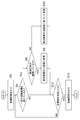
- FIG. 1 is a block diagram illustrating a configuration example of a system including a distance image acquisition device and a distance image processing device according to the first embodiment.
- FIG. 2 is a flowchart showing the flow of the distance image processing example in the first embodiment.
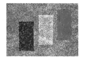
- FIG. 3 shows an example of a distance image including multiple reflection pixels and noise pixels.
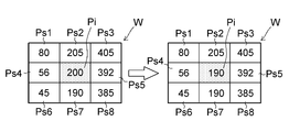
- FIG. 4 is an explanatory diagram used for explaining a clip processing example.
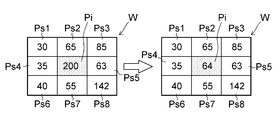
- FIG. 5 is an explanatory diagram used for explaining an example of noise processing.
- FIG. 6 is a block diagram illustrating a configuration example of the distance image acquisition apparatus according to the second embodiment.
- FIG. 7 is a flowchart illustrating a flow of a distance image processing example according to the second embodiment.
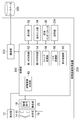
- FIG. 1 is a block diagram illustrating a configuration example of a system including a distance image acquisition device and a distance image processing device according to the first embodiment.
- the distance image acquisition device 10 includes a light emitting unit 12 that emits light, an optical system 16 that includes a lens 14 and a diaphragm 15, and an imaging unit 20 that includes an image sensor 18 having a light receiving surface in which a plurality of light receiving elements are two-dimensionally arranged.
- a client communication unit 22 that outputs and inputs information to and from an external device (distance image processing device 100 in this example), a client storage unit 24 that stores various types of information, and a program stored in the client storage unit 24 And a client control unit 40 that controls each unit of the distance image acquisition device 10.
- the light emitting unit 12 is configured by, for example, an LED (light emitting diode) that emits infrared light. Other light emitting devices may be used.
- the lens 14 of the optical system 16 guides the light emitted from the light emitting unit 12 and reflected by the distance measuring area corresponding to the angle of view of the lens 14 to the light receiving surface of the imaging element 18 of the imaging unit 20.
- the lens 14 may be composed of a plurality of lenses.
- CMOS complementary metal oxide semiconductor
- CCD charge coupled device
- Other imaging devices may be used.
- the imaging element 18 has a light receiving surface on which a plurality of light receiving elements are arranged.
- photoelectric conversion elements having a filter that allows infrared light to pass through are two-dimensionally arranged as light receiving elements on the light receiving surface.
- the client communication unit 22 is configured by a wired or wireless communication device.
- the client storage unit 24 includes, for example, a ROM (read only memory), a RAM (random access memory), and an EEPROM (electrically erasable programmable read only memory). Other storage devices may be used.
- the client control unit 40 is configured by, for example, a CPU (central processing unit).
- the client control unit 40 of this example includes a distance image generation unit 42 that generates a distance image based on the imaging result of the imaging unit 20.
- the distance image is an image composed of a plurality of pixels having distance values corresponding to the light flight time from the light emission of the light emitting unit 12 to the light reception of the imaging unit 20.
- the distance image processing apparatus 100 includes a display unit 32 that performs display for a user, an instruction input unit 34 that receives an instruction input from the user, a medium interface 36 that is an interface with a recording medium such as a memory card, and an external device ( In this example, the distance image acquisition device 10 and the database 300), a server communication unit 122 that outputs and inputs information, a server storage unit 124 that stores various types of information, and a distance image according to a program stored in the server storage unit 124 And a server control unit 140 that controls each unit of the processing apparatus 100.
- the display unit 32 is a display device, and is composed of, for example, an LCD (liquid crystal display).
- An OLED (Organic / Light / Emitting / Diode) display may be used.
- the instruction input unit 34 is configured by a touch panel arranged to cover the screen of the display unit 32, for example. You may comprise with a keyboard and a pointing device (for example, mouse). Other input devices such as a voice input device and a gesture input device may be used.
- the medium interface 36 reads information from the recording medium and writes information to the recording medium.
- the server communication unit 122 is configured by a wired or wireless communication device.
- the server communication unit 122 of this example is a form of a “distance image input unit” in the present invention, and inputs a distance image from the distance image acquisition device 10.
- the server storage unit 124 includes, for example, a ROM, a RAM, and an EEPROM. Other storage devices may be used.
- the server control unit 140 of this example includes a first determination unit 52 that determines a pixel having a distance value exceeding a certain distance range among a plurality of pixels of the distance image as an abnormal pixel, and a first determination unit 52
- a second discrimination unit 54 that discriminates the identified abnormal pixel into a first abnormal pixel that is continuous and a second abnormal pixel that is not continuous; and a distance value between the first abnormal pixels is a constant value
- a clip processing unit 56 that changes the distance value of the second abnormal pixel, a noise processing unit 58 that changes the distance value of the second abnormal pixel based on the distance value of the pixels around the second abnormal pixel, and a distance image displayed on the display unit 32
- Display control unit 60 to be configured.
- the first determination unit 52 of this example determines whether or not the distance value of each pixel of the distance image exceeds the upper limit value (for example, 1.0 m) of the short-distance measurement range, and the distance value exceeding the upper limit value. Is determined as an abnormal pixel.
- the upper limit value for example, 1.0 m
- the second discriminating unit 54 in this example discriminates the abnormal pixels discriminated by the first discriminating unit 52 into the first abnormal pixels that are continuous and the second abnormal pixels that are not continuous. That is, it is determined whether or not the pixel is an abnormal pixel (first abnormal pixel) due to multiple reflection.
- the pixel is a “first abnormal pixel” by counting the number of abnormal pixels in an area of a certain size with reference to each abnormal pixel in the distance image. For example, it is determined whether or not there are many abnormal pixels (for example, half or more) around the abnormal pixel of interest. That is, if the number of abnormal pixels counted in an area of a certain size based on the noticed abnormal pixel is a majority, the noticed abnormal pixel is determined to be the “first abnormal pixel”.
- the “constant size region” is, for example, a region having a predetermined pixel size centered on the abnormal pixel of interest (the abnormal pixel determined by the first determination unit 52).
- the “predetermined pixel size” is preferably N ⁇ N pixels (N is 3 to 7), and more preferably 3 ⁇ 3 pixels.
- first abnormal pixel is not limited to the above-described mode. What is necessary is just to detect that the abnormal pixel continues over several pixels as discrimination
- the clip processing unit 56 of this example changes the distance value of the first abnormal pixel to the upper limit value of the distance range of the short distance measurement.
- the noise processing unit 58 in this example performs noise removal processing using a filter such as a smoothing filter or a median filter.
- a filter such as a smoothing filter or a median filter.
- the smoothing filter include an averaging filter that gives an average value of peripheral pixels to abnormal pixels, and a Gaussian filter that increases the weight of peripheral pixels closer to the target pixel.
- the median filter gives a median value of peripheral pixels to abnormal pixels.
- the noise removal filter is not particularly limited to the above example.
- the “peripheral pixel” is a pixel located within a predetermined number of pixels from the abnormal pixel of interest (the abnormal pixel determined by the first determination unit 52).
- the “predetermined number of pixels” is preferably 1 to 3 pixels, and more preferably 1 pixel.
- the display control unit 60 of this example causes the display unit 32 to display a plurality of pixels of the distance image in a color corresponding to each distance value.
- the display control unit 60 indicates the distance value as a pixel value representing a color in which R (red), G (green), and B (blue) are the three primary colors.
- the database 300 of this example can store a distance image and correction information for correcting the distance image.
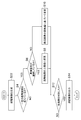
- FIG. 2 is a flowchart showing the flow of the distance image processing example in the first embodiment.
- the distance image processing of this example is executed by the server control unit 140 according to a program stored in the server storage unit 124.
- a distance image is input from the distance image acquisition device 10 by the server communication unit 122 (step S2).
- the distance image stored in the database 300 may be input from the database 300 by the server communication unit 122.
- the distance image is composed of a plurality of pixels having distance values corresponding to the light flight time from light emission of the light emitting unit 12 to light reception on the light receiving surface of the imaging unit 20.
- An example of the distance image illustrated in FIG. 3 includes multiple reflection pixels and noise pixels.
- the distance image in this example can be displayed in color on the display unit 32, and each pixel value of the distance image corresponds to the magnitude of the distance value. It is a value that indicates the attached color.
- a white continuous region is a region of the first abnormal pixel (which is an abnormal pixel due to multiple reflection).
- a minute white point is a second abnormal pixel (noise pixel).
- the first determination unit 52 determines whether or not the distance value exceeds the short-range measurement range for each pixel constituting the distance image (step S4). That is, the first determination unit 52 determines that a pixel having a distance value exceeding a certain distance range is an abnormal pixel. For example, when the short-range measurement range is 1.0 m or less, a pixel having a distance value exceeding 1.0 m is determined as an abnormal pixel.
- the second determination unit 54 determines whether the abnormal pixel is a continuous first abnormal pixel or a non-continuous second abnormal pixel. (Step S6).
- the clip processing unit 56 Then, clip processing is performed to change the distance value of the first abnormal pixel to a constant value in the distance range (in this example, the upper limit value of the measurement distance range) (step S8).
- the distance value (“200” in this example) of the target pixel Pi exceeds the upper limit value (eg, “190”) of the distance measurement range, and has a certain size (in this example).
- the pixels in the target window W (3 ⁇ 3 pixels) (the target pixel Pi and the peripheral pixels Ps1, Ps2, Ps3, Ps4, Ps5, Ps6, Ps7, Ps8), the same as the target pixel Pi (which is an abnormal pixel)
- the distance value of the target pixel Pi is set to the upper limit value (for example, “190”) of the measurement distance range. change.
- the noise processing unit 58 When it is determined that the pixel is the second abnormal pixel, that is, when it is determined that the abnormal pixel determined by the first determination unit 52 is not continuous (NO in step S6), the noise processing unit 58 Then, the distance value of the abnormal pixel is changed based on the distance value of the surrounding pixels (step S10).
- the noise processing unit 58 in this example performs smoothing on the second abnormal pixel.
- the distance value (for example, “200”) of the target pixel Pi exceeds the upper limit value (for example, “190”) of the distance measurement range, and the pixel (target pixel) in the target window W Among the pixels Pi and the surrounding pixels Ps1 to Ps8), the number of pixels having a distance value exceeding the upper limit “190” is less than half (four or less in this example) as in the target pixel Pi (is an abnormal pixel).
- the pixel value (eg, “200”) of the pixel of interest Pi is changed to the average value (eg, “64”) of the distance values of the surrounding pixels Ps1 to Ps8.
- the median value of the distance values of the peripheral pixels Ps1 to Ps8 may be changed.
- step S12 It is determined whether or not all pixels of the distance image have been determined (step S12). If there are pixels that have not yet been determined (NO in step S12), the process returns to step S4, and all pixels have been determined (step In the case of YES in S12), the distance image is output to the display unit 32 by the display control unit 60 (step S14). The plurality of pixels of the distance image are displayed on the display unit 32 in a color corresponding to each distance value.
- the server communication unit 122 may output the distance image to the database 300. A distance image may be output to the recording medium by the medium interface 36.
- FIG. 6 is a block diagram illustrating a configuration example of the distance image acquisition apparatus according to the second embodiment.
- symbol is attached
- the distance image acquisition apparatus 200 of the present embodiment includes a light emitting unit 12, an optical system 16, an imaging unit 20, a display unit 32, an instruction input unit 34, a medium interface 36, a communication unit 222, a storage unit 224, and a control unit 240. It consists of
- the communication unit 222 is configured by a wired or wireless communication device, and outputs and inputs information with an external device (in this example, the database 300).
- the storage unit 224 includes, for example, a ROM, a RAM, and an EEPROM, and stores various types of information.
- the control unit 240 is configured by a CPU, for example.
- the control unit 240 includes a distance image generation unit 42, a first determination unit 52, a second determination unit 54, a clip processing unit 56, a noise processing unit 58, and a display control unit 60. Generation processing, discrimination processing, clip processing, noise processing, and display control processing are executed.
- FIG. 7 is a flowchart showing a flow of a distance image processing example in the second embodiment.
- the distance image processing of this example is executed by the control unit 240 of the distance image acquisition device 200 according to a program stored in the storage unit 224 of the distance image acquisition device 200.
- the same steps as those in the distance image processing example of the first embodiment shown in FIG. 2 are denoted by the same reference numerals, and detailed description thereof is omitted.
- the distance image generation unit 42 of the distance image acquisition device 200 generates a distance image (step S22).
- the subsequent processing is the same as steps S4 to S14 in the first embodiment shown in FIG.
- Discrimination processing step S4 and step S6
- clip processing step S8
- noise processing step S10
- step S12 It is determined whether or not all pixels of the distance image have been determined (step S12). If there are pixels that have not yet been determined (NO in step S12), the process returns to step S4, and all pixels have been determined (step In the case of YES in S12), a distance image in which the pixel value of the abnormal pixel is changed is output (step S14).
- the determination threshold values of the first determination unit 52 and the second determination unit 54 are fixed is taken as an example.
- the determination threshold value may be variable.
- the determination threshold value of the first determination unit 52 may be variable. That is, the threshold value for determining whether or not the target pixel of the distance image is an abnormal pixel (hereinafter referred to as “abnormal pixel determination threshold value”) is variable.
- the setting input of the upper limit value of the measurement distance range is accepted by the instruction input unit 34.
- the instruction input unit 34 in this example is one form of the “setting input unit” in the present invention.
- the first determination unit 52 uses the upper limit value received by the instruction input unit 34 as an abnormal pixel determination threshold, and when the pixel value of the target pixel exceeds the upper limit value input by the instruction, the target pixel is an abnormal pixel. Determine that there is.
- the determination threshold value of the second determination unit 54 may be variable. That is, a threshold for determining whether or not to perform clipping processing on an abnormal pixel (hereinafter referred to as “processing determination threshold”) is variable. In other words, the second determination unit 54 switches the threshold used for determining whether or not the pixel is the first abnormal pixel.
- the second determination unit 54 switches the processing determination threshold according to the upper limit value of the measurement distance range.
- the second determination unit 54 switches the processing determination threshold according to the imaging sensitivity when the distance image is acquired.
Landscapes
- Engineering & Computer Science (AREA)
- Physics & Mathematics (AREA)
- General Physics & Mathematics (AREA)
- Radar, Positioning & Navigation (AREA)
- Remote Sensing (AREA)
- Computer Networks & Wireless Communication (AREA)
- Electromagnetism (AREA)
- Theoretical Computer Science (AREA)
- Multimedia (AREA)
- Computer Vision & Pattern Recognition (AREA)
- Optical Radar Systems And Details Thereof (AREA)
- Measurement Of Optical Distance (AREA)
- Image Processing (AREA)
- Image Analysis (AREA)
Abstract
近距離測定の場合に高精度且つ高視認性の距離画像を取得することができる距離画像処理装置、距離画像取得装置、及び距離画像処理方法を提供する。距離画像の複数の画素のうち一定の距離範囲を超えた距離値を持つ画素を異常画素と判別する第1の判別部(52)と、第1の判別部(52)により判別された異常画素を、更に連続している第1の異常画素と連続していない第2の異常画素とに判別する第2の判別部(54)と、第1の異常画素の距離値を一定値に変更するクリップ処理部(56)を備える。
Description
本発明は、光の飛行時間に対応した複数の距離値を含む距離画像に対する処理を行う距離画像処理装置、距離画像取得装置、及び距離画像処理方法に関し、特に近距離測定の場合に高精度且つ高視認性の距離画像を取得することを可能にする技術に関する。
発光部から発光して測距領域で反射された光をレンズにより撮像部の受光面に導き、その撮像部の撮像結果に基づいて、発光から受光までの光の飛行時間(TOF: time of flight)に対応した複数ポイントの距離値を算出し、視認可能な距離画像を取得するTOF方式の測距技術が知られている。
特許文献1には、TOF方式の測距において、近距離範囲を超えた距離値を排除することが記載されている。
特許文献2には、TOF方式の測距において、対象物の大きさに応じて平滑化フィルタのパラメータを決定し、距離画像の画素値を平滑化することが記載されている。
特許文献3には、TOF方式の測距において、多重反射の問題に対し、距離画像及び表面形状情報(表面の法線の方位角である)を同時に取得し、距離画像のうち距離値が空間的に不連続であり且つ表面形状が連続した領域を外乱領域と判定して除去し、その周囲の画素の距離値の中央値で補完することが記載されている。
TOF方式の測距では、多重反射に起因して正しい距離値を得られない場合がある。特に距離の測定範囲が近距離に限定されている場合、多重反射に起因した距離値の異常が顕著になる。例えば、TOF方式の測距を内視鏡装置に適用して距離画像を取得した場合、数十cm程度の測定距離範囲に対して、距離画像内に遠距離を示す外れ値が多数発生してしまうことがある。また、距離値の異常の発生原因は多重反射だけではなく、例えば高感度撮像の場合、距離画像内に電気的要因の微小ノイズの発生が顕著になる。
特許文献1には、近距離範囲を超えた距離値を排除することが記載されているにすぎない。
特許文献2には、距離画像の画素値を平滑化するノイズ除去技術が記載されているにすぎない。従って、近距離測定の場合には、多重反射に起因した距離値の異常が顕在化するため、高精度且つ高視認性の距離画像を出力できない可能性がある。なぜなら、多重反射に因り周辺の画素の半数以上が異常値を持つような場合には、異常値を周辺の画素の距離値に基づいて平滑化しても適切な値に補正できないからである。
特許文献3の技術では、距離画像を取得するための第1の撮像手段だけでなく、表面形状情報を取得するための第2の撮像手段が必要であるため、装置サイズ及び装置コストが増大する。また、多重反射が顕著である場合、高視認性の距離画像を出力できない可能性がある。なぜなら、多重反射に因り周辺の画素の半数以上が異常値を持つような場合には、外乱領域と判定された領域を周辺の画素の中央値で補完しても適切な距離値で補完できないからである。
上述の特許文献1~3には、距離画像のみに基づいて多重反射に起因した異常画素と電気的要因の微小ノイズ画素とを判別する技術が開示されておらず、また、多重反射に起因した異常画素と微小ノイズ画素とで画像処理を異ならせて高視認性の距離画像を提示するための技術についても開示されていない。従って、仮に上述の複数の従来技術を組み合わせることができたとしても、高精度且つ高視認性の距離画像を取得することは困難であるといえる。
本発明はこのような事情に鑑みてなされたもので、近距離測定の場合に高精度且つ高視認性の距離画像を取得することを可能にする距離画像処理装置、距離画像取得装置、及び距離画像処理方法を提供することを目的とする。
上述した目的を達成するため、本発明の第1の態様に係る距離画像処理装置は、発光から受光までの光飛行時間に対応した距離値を持つ複数の画素によって構成された距離画像を入力する距離画像入力部と、複数の画素のうち一定の距離範囲を超えた距離値を持つ画素を異常画素と判別する第1の判別部と、第1の判別部により判別された異常画素を、更に連続している第1の異常画素と連続していない第2の異常画素とに判別する第2の判別部と、第1の異常画素の距離値を一定値に変更するクリップ処理部と、を備える。
本態様によれば、複数の画素のうち一定の距離範囲を超えた距離値を持つ画素が異常画素と判別され、更に連続している第1の異常画素であると判別された場合に第1の異常画素の距離値が一定値に変更されるので、近距離測定で多重反射が顕在化した場合に従来よりも高精度且つ高視認性の距離画像を取得することが可能になる。
本発明の第2の態様に係る距離画像処理装置では、一定値は、一定の距離範囲の上限値であり、クリップ処理部は、第1の異常画素の距離値を距離範囲の上限値に変更する。本態様によれば、近距離測定で多重反射が顕在化した場合に、多重反射に因る外れ値が測定範囲である一定の距離範囲の上限値にクリップされるので、見易い距離画像を取得することが可能になる。
本発明の第3の態様に係る距離画像処理装置は、第2の異常画素の距離値を第2の異常画素の周辺にある画素の距離値に基づいて変更するノイズ処理部を備える。本態様によれば、多重反射に因る異常値の発生と共に、例えば高感度撮像に因る微小ノイズの発生が顕在化した場合に、微小ノイズの画素は周辺の画素の距離値に基づいて変更されるので、更に高精度且つ高視認性の距離画像を取得することができる。
本発明の第4の態様に係る距離画像処理装置では、第2の判別部は、第1の判別部により判別された各異常画素を基準とした一定サイズの領域内の異常画素の画素数に基づいて、第1の異常画素であるか否かの判別を行う。本態様によれば、多重反射に因る異常画素を適切に判別することが可能になる。
本発明の第5の態様に係る距離画像処理装置では、第2の判別部は、距離範囲の上限値に応じて、第1の異常画素であるか否かの判別に用いる閾値を切り換える。
本発明の第6の態様に係る距離画像処理装置では、第2の判別部は、距離画像を取得した際の撮像感度に応じて、第1の異常画素であるか否かの判別に用いる閾値を切り換える。
本発明の第7の態様に係る距離画像処理装置は、一定値の設定入力を受け付ける設定入力部を備える。
本発明の第8の態様に係る距離画像処理装置では、ノイズ処理部は、平滑化フィルタ、又はメディアンフィルタを用いてノイズ処理を行う。
本発明の第9の態様に係る距離画像取得装置は、距離画像の複数の画素をそれぞれの距離値に応じた色で表示デバイスに表示させる表示制御部を備える。
本発明の第10の態様に係る距離画像取得装置は、光を発光する発光部と、複数の受光素子が配列された受光面を有する撮像部と、発光部から発光されて測距領域で反射された光を撮像部の受光面に導く光学系と、撮像部の撮像結果に基づいて、発光部の発光から撮像部の受光面までの光飛行時間に対応した距離値を持つ複数の画素によって構成された距離画像を生成する距離画像生成部と、複数の画素のうち一定の距離範囲を超えた距離値を持つ画素を異常画素と判別する第1の判別部と、第1の判別部により判別された異常画素を、更に連続している第1の異常画素と連続していない第2の異常画素とに判別する第2の判別部と、第1の異常画素の距離値を一定値に変更するクリップ処理部と、を備える。
本発明の第11の態様に係る距離画像取得装置では、一定値は、一定の距離範囲の上限値である。
本発明の第12の態様に係る距離画像取得装置は、第2の異常画素の距離値を第2の異常画素の周辺にある画素の距離値に基づいて変更するノイズ処理部を備える。
本発明の第13の態様に係る距離画像処理方法は、発光から受光までの光飛行時間に対応した距離値を持つ複数の画素によって構成された距離画像を入力するステップと、複数の画素のうち一定の距離範囲を超えた距離値を持つ画素を異常画素と判別するステップと、判別された異常画素を、更に連続している第1の異常画素と連続していない第2の異常画素とに判別するステップと、第1の異常画素の距離値を一定値に変更するステップと、を含む。
本発明の第14の態様に係る距離画像処理方法では、一定値は、一定の距離範囲の上限値である。
本発明の第15の態様に係る距離画像処理方法は、第2の異常画素の距離値を第2の異常画素の周辺にある画素の距離値に基づいて変更するステップを含む。
本発明よれば、近距離測定の場合に高精度且つ高視認性の距離画像を取得することが可能になる。
以下、添付図面に従って、本発明に係る距離画像処理装置、距離画像取得装置、及び距離画像処理方法を実施するための形態について説明する。
[第1の実施形態]
図1は、第1の実施形態における距離画像取得装置及び距離画像処理装置を含むシステムの構成例を示すブロック図である。
図1は、第1の実施形態における距離画像取得装置及び距離画像処理装置を含むシステムの構成例を示すブロック図である。
距離画像取得装置10は、光を発光する発光部12と、レンズ14及び絞り15を含む光学系16と、複数の受光素子が二次元配列された受光面を有する撮像素子18を含む撮像部20と、外部の装置(本例では距離画像処理装置100)と情報の出力及び入力を行うクライアント通信部22と、各種の情報を記憶するクライアント記憶部24と、クライアント記憶部24に記憶されたプログラムに従って距離画像取得装置10の各部を制御するクライアント制御部40とを備える。
発光部12は、例えば赤外光を発光するLED(light emitting diode)によって構成される。他の発光デバイスを用いてもよい。
光学系16のレンズ14は、発光部12から発光されてレンズ14の画角に対応する測距領域で反射された光を、撮像部20の撮像素子18の受光面に導く。レンズ14は、複数枚のレンズで構成されていてもよい。
撮像部20の撮像素子18として、例えばCMOS(complementary metal oxide semiconductor)撮像センサ、又はCCD(charge coupled device)撮像センサを用いる。他の撮像デバイスを用いてもよい。撮像素子18は、複数の受光素子が配列された受光面を有する。本例の撮像素子18は、その受光面に、赤外光を通過させるフィルタを持つ光電変換素子が、受光素子として二次元配列されている。
クライアント通信部22は、有線又は無線の通信デバイスによって構成される。
クライアント記憶部24は、例えばROM(read only memory)、RAM(random access memory)及びEEPROM(electrically erasable programmable read only memory)を含んで構成される。他の記憶デバイスを用いてもよい。
クライアント制御部40は、例えばCPU(central processing unit)によって構成される。
本例のクライアント制御部40は、撮像部20の撮像結果に基づいて、距離画像を生成する距離画像生成部42を含んで構成される。距離画像は、発光部12の発光から撮像部20の受光までの光飛行時間に対応した距離値を持つ複数の画素によって構成された画像である。
距離画像処理装置100は、ユーザに対する表示を行う表示部32と、ユーザからの指示入力を受け付ける指示入力部34と、メモリカードなどの記録媒体とのインターフェースである媒体インターフェース36と、外部の装置(本例では距離画像取得装置10及びデータベース300)と情報の出力及び入力を行うサーバ通信部122と、各種の情報を記憶するサーバ記憶部124と、サーバ記憶部124に記憶されたプログラムに従って距離画像処理装置100の各部を制御するサーバ制御部140とを備える。
表示部32は、表示デバイスであり、例えばLCD(liquid crystal display)によって構成される。OLED(Organic Light Emitting Diode)ディスプレイを用いてもよい。
指示入力部34は、例えば表示部32の画面を覆うように配置されたタッチパネルによって構成される。キーボード及びポインティングデバイス(例えばマウス)によって構成してもよい。音声入力デバイス、ジェスチャー入力デバイス等、他の入力デバイスを用いてもよい。
媒体インターフェース36は、記録媒体からの情報の読込み及び記録媒体に対する情報の書込みを行う。
サーバ通信部122は、有線又は無線の通信デバイスによって構成される。本例のサーバ通信部122は、本発明における「距離画像入力部」の一形態であり、距離画像取得装置10から距離画像を入力する。
サーバ記憶部124は、例えばROM、RAM及びEEPROMを含んで構成される。他の記憶デバイスを用いてもよい。
本例のサーバ制御部140は、距離画像の複数の画素のうち一定の距離範囲を超えた距離値を持つ画素を異常画素と判別する第1の判別部52と、第1の判別部52により判別された異常画素を、更に連続している第1の異常画素と連続していない第2の異常画素とに判別する第2の判別部54と、第1の異常画素の距離値を一定値に変更するクリップ処理部56と、第2の異常画素の距離値を第2の異常画素の周辺にある画素の距離値に基づいて変更するノイズ処理部58と、距離画像を表示部32に表示させる表示制御部60とを含んで構成される。
本例の第1の判別部52は、距離画像の各画素の距離値が近距離の測定範囲の上限値(例えば1.0m)を超えたか否かを判定し、上限値を超えた距離値を持つ画素を異常画素であると判別する。
本例の第2の判別部54は、第1の判別部52により判別された異常画素を、更に連続している第1の異常画素と連続していない第2の異常画素とに判別する。つまり、多重反射に起因した異常画素(第1の異常画素)であるか否かを判別する。
「第1の異常画素」であるか否かの判別には、各種の態様がある。
例えば、距離画像における各異常画素を基準とした一定サイズの領域内の異常画素の画素数をカウントすることにより、「第1の異常画素」であるか否かを判別する態様がある。例えば、注目した異常画素の周辺にも異常画素が多数(例えば半数以上)存在するか否かを判別する。つまり、注目した異常画素を基準とした一定サイズの領域内における異常画素のカウント数が過半数であるならば、注目した異常画素を「第1の異常画素」であると判別する。ここで、「一定サイズの領域」とは、例えば、注目する異常画素(第1の判別部52により判別された異常画素である)を中心とした所定の画素サイズの領域である。「所定の画素サイズ」は、好ましくはN×N画素(Nは3から7)であり、より好ましくは3×3画素であればよい。
尚、「第1の異常画素」の判別態様は、前述の態様には限定されない。「第1の異常画素」の判別として、複数画素に亘り異常画素が連続していることを検出すればよい。
本例のクリップ処理部56は、第1の異常画素の距離値を、近距離測定の距離範囲の上限値に変更する。
本例のノイズ処理部58は、平滑化フィルタ、メディアンフィルタなどのフィルタを用いて、ノイズ除去処理を行う。平滑化フィルタとして、周辺画素の平均値を異常画素に対して与える平均化フィルタや、注目画素に近い周辺画素ほど重み付けを大きくするガウシアンフィルタなどが挙げられる。メディアンフィルタは、周辺画素の中央値を異常画素に対して与える。尚、ノイズ除去フィルタは、前述の例には特に限定されない。
ここで、「周辺画素」とは、注目する異常画素(第1の判別部52により判別された異常画素である)から所定の画素数以内に位置する画素である。「所定の画素数」は、好ましくは1画素から3画素であり、より好ましくは1画素であればよい。
本例の表示制御部60は、距離画像の複数の画素をそれぞれの距離値に応じた色で表示部32に表示させる。本例の表示制御部60は、距離値をR(赤),G(緑),B(青)を三原色とした色を表す画素値で示す。
本例のデータベース300は、距離画像、及び距離画像を補正するための補正情報を記憶することができる。
次に、本発明に係る距離画像処理方法を適用した距離画像処理例を説明する。
図2は、第1の実施形態における距離画像処理例の流れを示すフローチャートである。本例の距離画像処理は、サーバ制御部140により、サーバ記憶部124に記憶されたプログラムに従って実行される。
まず、サーバ通信部122により、距離画像取得装置10から、距離画像を入力する(ステップS2)。データベース300に記憶された距離画像を、サーバ通信部122によりデータベース300から入力してもよい。距離画像は、発光部12の発光から撮像部20の受光面での受光までの光飛行時間に対応した距離値を持つ複数の画素によって構成されている。図3に示す距離画像の一例は、多重反射画素及びノイズ画素を含む。尚、図3では、図示の便宜上グレイスケールで表されているが、本例の距離画像は、表示部32にカラーで表示可能であり、距離画像の各画素値は距離値の大きさに対応付けられた色を示す値である。図中、白色の連続した領域が第1の異常画素(多重反射に起因した異常画素である)の領域である。また、図中、白色の微小な点が第2の異常画素(ノイズ画素)である。
次に、第1の判別部52により、距離画像を構成する画素ごとに、距離値が近距離の測定範囲を超えているか否かを判別する(ステップS4)。つまり、第1の判別部52により、一定の距離範囲を超えた距離値を持つ画素を異常画素であると判別する。例えば、近距離の測定範囲が1.0m以下である場合、その1.0mを超える距離値を持つ画素を異常画素と判別する。
異常画素と判別された場合(ステップS4でYESの場合)、第2の判別部54により、異常画素が、連続している第1の異常画素であるか、連続していない第2の異常画素であるかを判別する(ステップS6)。第1の異常画素であると判別された場合、つまり第1の判別部52により判別された異常画素が連続していると判別された場合(ステップS6でYESの場合)、クリップ処理部56により、第1の異常画素の距離値を距離範囲の一定値(本例では測定距離範囲の上限値)に変更するクリップ処理を行う(ステップS8)。
例えば、図4に示すように、注目画素Piの距離値(本例では「200」)が測距範囲の上限値(例えば「190」)を超えており、且つ、一定のサイズ(本例では3×3画素)である注目ウィンドウW内の画素(注目画素Pi及び周辺画素Ps1、Ps2、Ps3、Ps4、Ps5、Ps6、Ps7、Ps8)のうち、注目画素Pi(異常画素である)と同様に上限値である「190」を超えた距離値を持つ画素が過半数(本例では5個以上)である場合、注目画素Piの距離値を測定距離範囲の上限値(例えば「190」)に変更する。
第2の異常画素であると判別された場合、つまり第1の判別部52により判別された異常画素が連続してないと判別された場合(ステップS6でNOの場合)、ノイズ処理部58により、異常画素の距離値を周辺画素の距離値に基づいて変更する(ステップS10)。
本例のノイズ処理部58は、第2の異常画素に対して、平滑化を行う。例えば、図5に示すように、注目画素Piの距離値(例えば「200」)が測距範囲の上限値(例えば「190」)を超えており、且つ、注目ウィンドウW内の画素(注目画素Pi及び周辺画素Ps1~Ps8)のうち、注目画素Pi(異常画素である)と同様に上限値である「190」を超えた距離値を持つ画素が半数以下(本例では4個以下)である場合、注目画素Piの画素値(例えば「200」)を周辺画素Ps1~Ps8の距離値の平均値(例えば「64」)に変更する。周辺画素Ps1~Ps8の距離値の中央値に変更してもよい。
距離画像の全画素を判別したか否かを判定し(ステップS12)、まだ判別していない画素が有る場合(ステップS12でNOの場合)、ステップS4に戻り、全画素を判別した場合(ステップS12でYESの場合)、表示制御部60により、距離画像を表示部32に対し出力する(ステップS14)。距離画像の複数の画素は、それぞれの距離値に応じた色で表示部32に表示される。サーバ通信部122により、距離画像をデータベース300に対して出力してもよい。媒体インターフェース36により、距離画像を記録媒体に対して出力してもよい。
[第2の実施形態]
図6は、第2の実施形態における距離画像取得装置の構成例を示すブロック図である。尚、図1に示した第1の実施形態の構成例と同じ構成要素には、同じ符号を付してあり、詳細な説明を省略する。
図6は、第2の実施形態における距離画像取得装置の構成例を示すブロック図である。尚、図1に示した第1の実施形態の構成例と同じ構成要素には、同じ符号を付してあり、詳細な説明を省略する。
本実施形態の距離画像取得装置200は、発光部12、光学系16、撮像部20、表示部32、指示入力部34、媒体インターフェース36、通信部222、記憶部224、及び制御部240を含んで構成されている。
通信部222は、有線又は無線の通信デバイスによって構成されており、外部の装置(本例ではデータベース300)と情報の出力及び入力を行う。記憶部224は、例えばROM、RAM及びEEPROMを含んで構成されており、各種の情報を記憶する。制御部240は、例えばCPUによって構成される。制御部240は、距離画像生成部42、第1の判別部52、第2の判別部54、クリップ処理部56、ノイズ処理部58、及び表示制御部60を含んで構成されており、距離画像生成処理、判別処理、クリップ処理、ノイズ処理及び表示制御処理を実行する。
図7は、第2の実施形態における距離画像処理例の流れを示すフローチャートである。本例の距離画像処理は、距離画像取得装置200の制御部240により、距離画像取得装置200の記憶部224に記憶されたプログラムに従って実行される。尚、図2に示した第1の実施形態の距離画像処理例と同じステップには、同じ符号を付してあり、詳細な説明を省略する。
本実施形態では、距離画像取得装置200の距離画像生成部42により、距離画像を生成する(ステップS22)。その後の処理は図2に示した第1の実施形態におけるステップS4~S14と同様である。距離画像に対して、判別処理(ステップS4及びステップS6)、クリップ処理(ステップS8)、ノイズ処理(ステップS10)が実行される。距離画像の全画素を判別したか否かを判定し(ステップS12)、まだ判別していない画素が有る場合(ステップS12でNOの場合)、ステップS4に戻り、全画素を判別した場合(ステップS12でYESの場合)、異常画素の画素値が変更された距離画像を出力する(ステップS14)。
[判別の変形例]
第1の判別部52及び第2の判別部54による判別の変形例について、説明する。
第1の判別部52及び第2の判別部54による判別の変形例について、説明する。
上述の第1の実施形態及び第2の実施形態では、本発明の理解を容易にするため、第1の判別部52及び第2の判別部54の判別用閾値が固定である場合を例に説明したが、判別用閾値を可変としてもよい。
<第1の判別部用の閾値>
第1の判別部52の判別用閾値を可変としてよい。つまり、距離画像の注目画素が異常画素であるか否かを判別するための閾値(以下「異常画素判別用閾値」という)を可変とする。
第1の判別部52の判別用閾値を可変としてよい。つまり、距離画像の注目画素が異常画素であるか否かを判別するための閾値(以下「異常画素判別用閾値」という)を可変とする。
例えば、指示入力部34により、測定距離範囲の上限値の設定入力を受け付ける。本例の指示入力部34は、本発明における「設定入力部」の一形態である。第1の判別部52は、指示入力部34により受け付けた上限値を異常画素判別用閾値として用い、注目画素の画素値が、指示入力された上限値を超えた場合、注目画素が異常画素であると判別する。
<第2の判別部用の閾値>
第2の判別部54の判別用閾値を可変としてよい。つまり、異常画素に対してクリップ処理を行うか否かを判別するための閾値(以下「処理判別用閾値」という)を可変とする。言い換えると、第2の判別部54は、第1の異常画素であるか否かの判別に用いる閾値を切り換える。
第2の判別部54の判別用閾値を可変としてよい。つまり、異常画素に対してクリップ処理を行うか否かを判別するための閾値(以下「処理判別用閾値」という)を可変とする。言い換えると、第2の判別部54は、第1の異常画素であるか否かの判別に用いる閾値を切り換える。
第1に、第2の判別部54は、測定距離範囲の上限値に応じて、処理判別用閾値を切り換えることが、好ましい。
第2に、第2の判別部54は、距離画像を取得した際の撮像感度に応じて、処理判別用閾値を切り換えることが、好ましい。
以上、本発明を実施するための形態に関して説明してきたが、本発明は上述した実施形態及び変形例に限定されず、本発明の主旨を逸脱しない範囲で種々の変形が可能である。
10、200 距離画像取得装置
12 発光部
14 レンズ
15 絞り
16 光学系
18 撮像素子
20 撮像部
22 クライアント通信部
24 クライアント記憶部
32 表示部
34 指示入力部
36 媒体インターフェース
40 クライアント制御部
42 距離画像生成部
52 第1の判別部
54 第2の判別部
56 クリップ処理部
58 ノイズ処理部
60 表示制御部
100 距離画像処理装置
122 サーバ通信部
124 サーバ記憶部
140 サーバ制御部
222 通信部
224 記憶部
240 制御部
300 データベース
Pi 注目画素
Ps1、Ps2、Ps3、Ps4、Ps5、Ps6、Ps7、Ps8 周辺画素
W 注目ウィンドウ
Claims (15)
- 発光から受光までの光飛行時間に対応した距離値を持つ複数の画素によって構成された距離画像を入力する距離画像入力部と、
前記複数の画素のうち一定の距離範囲を超えた距離値を持つ画素を異常画素と判別する第1の判別部と、
前記第1の判別部により判別された前記異常画素を、更に連続している第1の異常画素と連続していない第2の異常画素とに判別する第2の判別部と、
前記第1の異常画素の距離値を一定値に変更するクリップ処理部と、
を備える距離画像処理装置。 - 前記一定値は、前記一定の距離範囲の上限値であり、
前記クリップ処理部は、前記第1の異常画素の距離値を前記距離範囲の上限値に変更する、
請求項1に記載の距離画像処理装置。 - 前記第2の異常画素の距離値を前記第2の異常画素の周辺にある画素の距離値に基づいて変更するノイズ処理部を備える、
請求項1または2に記載の距離画像処理装置。 - 前記第2の判別部は、前記第1の判別部により判別された各前記異常画素を基準とした一定サイズの領域内の前記異常画素の画素数に基づいて、前記第1の異常画素であるか否かの判別を行う、
請求項1から3のうちいずれか一項に記載の距離画像処理装置。 - 前記第2の判別部は、前記距離範囲の上限値に応じて、前記第1の異常画素であるか否かの判別に用いる閾値を切り換える、
請求項1から4のうちいずれか一項に記載の距離画像処理装置。 - 前記第2の判別部は、前記距離画像を取得した際の撮像感度に応じて、前記第1の異常画素であるか否かの判別に用いる閾値を切り換える、
請求項1から4のうちいずれか一項に記載の距離画像処理装置。 - 前記一定値の設定入力を受け付ける設定入力部を備える、
請求項1から6のうちいずれか一項に記載の距離画像処理装置。 - 前記ノイズ処理部は、平滑化フィルタ、又はメディアンフィルタを用いてノイズ処理を行う、
請求項3に記載の距離画像処理装置。 - 前記距離画像の前記複数の画素をそれぞれの前記距離値に応じた色で表示デバイスに表示させる表示制御部を備える、
請求項1から8のうちいずれか一項に記載の距離画像処理装置。 - 光を発光する発光部と、
複数の受光素子が配列された受光面を有する撮像部と、
前記発光部から発光されて測距領域で反射された光を前記撮像部の前記受光面に導く光学系と、
前記撮像部の撮像結果に基づいて、前記発光部の発光から前記撮像部の前記受光面までの光飛行時間に対応した距離値を持つ複数の画素によって構成された距離画像を生成する
距離画像生成部と、
前記複数の画素のうち一定の距離範囲を超えた距離値を持つ画素を異常画素と判別する第1の判別部と、
前記第1の判別部により判別された前記異常画素を、更に連続している第1の異常画素と連続していない第2の異常画素とに判別する第2の判別部と、
前記第1の異常画素の距離値を一定値に変更するクリップ処理部と、
を備える距離画像取得装置。 - 前記一定値は、前記一定の距離範囲の上限値である、
請求項10に記載の距離画像取得装置。 - 前記第2の異常画素の距離値を前記第2の異常画素の周辺にある画素の距離値に基づいて変更するノイズ処理部を備える、
請求項10または11に記載の距離画像取得装置。 - 発光から受光までの光飛行時間に対応した距離値を持つ複数の画素によって構成された距離画像を入力するステップと、
前記複数の画素のうち一定の距離範囲を超えた距離値を持つ画素を異常画素と判別するステップと、
前記判別された前記異常画素を、更に連続している第1の異常画素と連続していない第2の異常画素とに判別するステップと、
前記第1の異常画素の距離値を一定値に変更するステップと、
を含む距離画像処理方法。 - 前記一定値は、前記一定の距離範囲の上限値である、
請求項13に記載の距離画像処理方法。 - 前記第2の異常画素の距離値を前記第2の異常画素の周辺にある画素の距離値に基づいて変更するステップを含む、
請求項13または14に記載の距離画像処理方法。
Priority Applications (3)
| Application Number | Priority Date | Filing Date | Title |
|---|---|---|---|
| CN201780019927.1A CN108885265A (zh) | 2016-03-31 | 2017-03-15 | 距离图像处理装置、距离图像获取装置及距离图像处理方法 |
| JP2018508994A JP6630432B2 (ja) | 2016-03-31 | 2017-03-15 | 距離画像処理装置、距離画像取得装置、及び距離画像処理方法 |
| US16/138,026 US20190026911A1 (en) | 2016-03-31 | 2018-09-21 | Distance image processing device, distance image acquisition device, and distance image processing method |
Applications Claiming Priority (2)
| Application Number | Priority Date | Filing Date | Title |
|---|---|---|---|
| JP2016071923 | 2016-03-31 | ||
| JP2016-071923 | 2016-03-31 |
Related Child Applications (1)
| Application Number | Title | Priority Date | Filing Date |
|---|---|---|---|
| US16/138,026 Continuation US20190026911A1 (en) | 2016-03-31 | 2018-09-21 | Distance image processing device, distance image acquisition device, and distance image processing method |
Publications (1)
| Publication Number | Publication Date |
|---|---|
| WO2017169782A1 true WO2017169782A1 (ja) | 2017-10-05 |
Family
ID=59965433
Family Applications (1)
| Application Number | Title | Priority Date | Filing Date |
|---|---|---|---|
| PCT/JP2017/010386 WO2017169782A1 (ja) | 2016-03-31 | 2017-03-15 | 距離画像処理装置、距離画像取得装置、及び距離画像処理方法 |
Country Status (4)
| Country | Link |
|---|---|
| US (1) | US20190026911A1 (ja) |
| JP (1) | JP6630432B2 (ja) |
| CN (1) | CN108885265A (ja) |
| WO (1) | WO2017169782A1 (ja) |
Cited By (2)
| Publication number | Priority date | Publication date | Assignee | Title |
|---|---|---|---|---|
| JP2020193957A (ja) * | 2019-05-30 | 2020-12-03 | ファナック株式会社 | 測距異常を補正する距離画像生成装置 |
| WO2020255598A1 (ja) * | 2019-06-20 | 2020-12-24 | ヌヴォトンテクノロジージャパン株式会社 | 測距撮像装置 |
Families Citing this family (2)
| Publication number | Priority date | Publication date | Assignee | Title |
|---|---|---|---|---|
| CN115643809A (zh) * | 2019-09-26 | 2023-01-24 | 深圳市大疆创新科技有限公司 | 点云探测系统的信号处理方法和点云探测系统 |
| CN112824933A (zh) * | 2019-11-19 | 2021-05-21 | 北京小米移动软件有限公司 | 测距方法、测距装置及电子设备 |
Citations (3)
| Publication number | Priority date | Publication date | Assignee | Title |
|---|---|---|---|---|
| JP2002277239A (ja) * | 2001-03-19 | 2002-09-25 | Matsushita Electric Works Ltd | 距離測定装置 |
| JP2011016421A (ja) * | 2009-07-08 | 2011-01-27 | Higashi Nippon Transportec Kk | 支障物検知装置及びこれを備えたプラットホームドアシステム並びに支障物検知方法 |
| US20120134598A1 (en) * | 2010-11-26 | 2012-05-31 | Samsung Electronics Co., Ltd. | Depth Sensor, Method Of Reducing Noise In The Same, And Signal Processing System Including The Same |
Family Cites Families (18)
| Publication number | Priority date | Publication date | Assignee | Title |
|---|---|---|---|---|
| JPH04291127A (ja) * | 1991-03-20 | 1992-10-15 | Hitachi Ltd | 画像処理型状態監視装置の異常判定面積表示方法 |
| JPH05135181A (ja) * | 1991-11-08 | 1993-06-01 | Mitsubishi Electric Corp | 異常検出装置 |
| JP2007240275A (ja) * | 2006-03-07 | 2007-09-20 | Olympus Corp | 距離計測装置・撮像装置、距離計測方法・撮像方法、距離計測プログラム・撮像プログラムおよび記憶媒体 |
| JP2010193178A (ja) * | 2009-02-18 | 2010-09-02 | Olympus Corp | 画像処理装置及び方法並びにプログラム |
| KR101722641B1 (ko) * | 2010-12-23 | 2017-04-04 | 삼성전자주식회사 | 3차원 영상 획득 장치 및 상기 3차원 영상 획득 장치에서 깊이 정보를 추출하는 방법 |
| US9426444B2 (en) * | 2011-06-24 | 2016-08-23 | Softkinetic Software | Depth measurement quality enhancement |
| CN103988490B (zh) * | 2011-12-13 | 2018-05-22 | 索尼公司 | 图像处理装置、图像处理方法和记录介质 |
| JP5791155B2 (ja) * | 2012-04-23 | 2015-10-07 | 富士フイルム株式会社 | 画像処理方法、画像処理装置、画像形成装置及びインクジェット記録装置 |
| JP2014053783A (ja) * | 2012-09-07 | 2014-03-20 | Nikon Corp | 画像処理装置および撮像装置 |
| JP5540217B2 (ja) * | 2012-09-19 | 2014-07-02 | オプテックス株式会社 | レーザースキャンセンサ |
| KR101977711B1 (ko) * | 2012-10-12 | 2019-05-13 | 삼성전자주식회사 | 깊이 센서, 이의 이미지 캡쳐 방법, 및 상기 깊이 센서를 포함하는 이미지 처리 시스템 |
| JP6367827B2 (ja) * | 2012-12-28 | 2018-08-01 | ノキア テクノロジーズ オサケユイチア | 距離センサ・カメラからのデータをノイズ除去する方法および装置 |
| JP5802858B2 (ja) * | 2013-03-05 | 2015-11-04 | 富士フイルム株式会社 | 撮像装置、画像処理装置、画像処理方法及びプログラム |
| KR102136850B1 (ko) * | 2013-11-12 | 2020-07-22 | 삼성전자 주식회사 | 깊이 센서, 및 이의 동작 방법 |
| KR102198852B1 (ko) * | 2014-03-24 | 2021-01-05 | 삼성전자 주식회사 | 홍채 인식 장치 및 이를 포함하는 모바일 장치 |
| KR101661850B1 (ko) * | 2014-04-17 | 2016-09-30 | 가부시키가이샤 모르포 | 화상 처리 장치, 화상 처리 방법, 화상 처리 프로그램 및 기록 매체 |
| JP6507529B2 (ja) * | 2014-08-29 | 2019-05-08 | 株式会社デンソー | 光飛行型測距装置 |
| JP2020022135A (ja) * | 2018-08-03 | 2020-02-06 | オリンパス株式会社 | 欠陥画素補正装置、撮像装置、欠陥画素補正方法 |
-
2017
- 2017-03-15 JP JP2018508994A patent/JP6630432B2/ja active Active
- 2017-03-15 WO PCT/JP2017/010386 patent/WO2017169782A1/ja active Application Filing
- 2017-03-15 CN CN201780019927.1A patent/CN108885265A/zh not_active Withdrawn
-
2018
- 2018-09-21 US US16/138,026 patent/US20190026911A1/en not_active Abandoned
Patent Citations (3)
| Publication number | Priority date | Publication date | Assignee | Title |
|---|---|---|---|---|
| JP2002277239A (ja) * | 2001-03-19 | 2002-09-25 | Matsushita Electric Works Ltd | 距離測定装置 |
| JP2011016421A (ja) * | 2009-07-08 | 2011-01-27 | Higashi Nippon Transportec Kk | 支障物検知装置及びこれを備えたプラットホームドアシステム並びに支障物検知方法 |
| US20120134598A1 (en) * | 2010-11-26 | 2012-05-31 | Samsung Electronics Co., Ltd. | Depth Sensor, Method Of Reducing Noise In The Same, And Signal Processing System Including The Same |
Cited By (3)
| Publication number | Priority date | Publication date | Assignee | Title |
|---|---|---|---|---|
| JP2020193957A (ja) * | 2019-05-30 | 2020-12-03 | ファナック株式会社 | 測距異常を補正する距離画像生成装置 |
| WO2020255598A1 (ja) * | 2019-06-20 | 2020-12-24 | ヌヴォトンテクノロジージャパン株式会社 | 測距撮像装置 |
| JP7411656B2 (ja) | 2019-06-20 | 2024-01-11 | ヌヴォトンテクノロジージャパン株式会社 | 測距撮像装置 |
Also Published As
| Publication number | Publication date |
|---|---|
| US20190026911A1 (en) | 2019-01-24 |
| JP6630432B2 (ja) | 2020-01-15 |
| CN108885265A (zh) | 2018-11-23 |
| JPWO2017169782A1 (ja) | 2019-02-14 |
Similar Documents
| Publication | Publication Date | Title |
|---|---|---|
| US10085002B2 (en) | RGB-IR sensor, and method and apparatus for obtaining 3D image by using same | |
| WO2017169782A1 (ja) | 距離画像処理装置、距離画像取得装置、及び距離画像処理方法 | |
| US10824906B2 (en) | Image processing device, non-transitory computer readable storage medium, and image processing system | |
| JP6555811B2 (ja) | 顕微鏡システム、特定方法、及び、プログラム | |
| KR20160073866A (ko) | 홍채 인식 장치, 이를 포함하는 홍채 인식 시스템 및 상기 홍채 인식 시스템의 동작 방법 | |
| US20180184071A1 (en) | Photographing device and method for obtaining depth information | |
| US10931933B2 (en) | Calibration guidance system and operation method of a calibration guidance system | |
| EP3035104A2 (en) | Microscope system and setting value calculation method | |
| EP2728392A1 (en) | Microscope system | |
| US9521397B2 (en) | System and method for selecting a two-dimensional region of interest using a range sensor | |
| US10880540B2 (en) | 3D depth image acquiring method and apparatus, and image acquisition device | |
| JP2015173891A (ja) | 測定装置、画像表示装置、及びその制御方法 | |
| US8655024B2 (en) | Displacement detection device and displacement detection method thereof | |
| US20180203116A1 (en) | Distance measurement device, distance measurement method, and distance measurement program | |
| CN103376897A (zh) | 用于确定在所投影的图像的光锥中执行的手势的方法和设备 | |
| JP5251841B2 (ja) | 画像処理装置および画像処理プログラム | |
| US20220294990A1 (en) | Information processing device, imaging device, information processing method, and program | |
| CN109300091B (zh) | 辐射亮度校正方法及装置 | |
| JP6482589B2 (ja) | カメラ校正装置 | |
| US20130162601A1 (en) | Optical touch system | |
| JP6422761B2 (ja) | 顕微鏡システム、及び、z位置と補正装置の設定値との関係算出方法 | |
| KR20230098661A (ko) | 다중 디스플레이 밝기 모드를 위한 원활한 전환 | |
| JP2012185030A (ja) | 色ムラ判別装置、色ムラ判別方法及び表示装置 | |
| CN114365189A (zh) | 影像配准装置、图像生成系统、影像配准方法及影像配准程序 | |
| JP2016114796A (ja) | 顕微鏡システム、関数算出方法、及び、プログラム |
Legal Events
| Date | Code | Title | Description |
|---|---|---|---|
| WWE | Wipo information: entry into national phase |
Ref document number: 2018508994 Country of ref document: JP |
|
| NENP | Non-entry into the national phase |
Ref country code: DE |
|
| 121 | Ep: the epo has been informed by wipo that ep was designated in this application |
Ref document number: 17774326 Country of ref document: EP Kind code of ref document: A1 |
|
| 122 | Ep: pct application non-entry in european phase |
Ref document number: 17774326 Country of ref document: EP Kind code of ref document: A1 |