WO2017169530A1 - プレッシャレギュレータ及び燃料供給装置 - Google Patents
プレッシャレギュレータ及び燃料供給装置 Download PDFInfo
- Publication number
- WO2017169530A1 WO2017169530A1 PCT/JP2017/008695 JP2017008695W WO2017169530A1 WO 2017169530 A1 WO2017169530 A1 WO 2017169530A1 JP 2017008695 W JP2017008695 W JP 2017008695W WO 2017169530 A1 WO2017169530 A1 WO 2017169530A1
- Authority
- WO
- WIPO (PCT)
- Prior art keywords
- fuel
- valve body
- space
- communication hole
- branched
- Prior art date
- Legal status (The legal status is an assumption and is not a legal conclusion. Google has not performed a legal analysis and makes no representation as to the accuracy of the status listed.)
- Ceased
Links
Images


Classifications
-
- F—MECHANICAL ENGINEERING; LIGHTING; HEATING; WEAPONS; BLASTING
- F02—COMBUSTION ENGINES; HOT-GAS OR COMBUSTION-PRODUCT ENGINE PLANTS
- F02M—SUPPLYING COMBUSTION ENGINES IN GENERAL WITH COMBUSTIBLE MIXTURES OR CONSTITUENTS THEREOF
- F02M37/00—Apparatus or systems for feeding liquid fuel from storage containers to carburettors or fuel-injection apparatus; Arrangements for purifying liquid fuel specially adapted for, or arranged on, internal-combustion engines
- F02M37/0011—Constructional details; Manufacturing or assembly of elements of fuel systems; Materials therefor
- F02M37/0023—Valves in the fuel supply and return system
- F02M37/0029—Pressure regulator in the low pressure fuel system
-
- F—MECHANICAL ENGINEERING; LIGHTING; HEATING; WEAPONS; BLASTING
- F02—COMBUSTION ENGINES; HOT-GAS OR COMBUSTION-PRODUCT ENGINE PLANTS
- F02M—SUPPLYING COMBUSTION ENGINES IN GENERAL WITH COMBUSTIBLE MIXTURES OR CONSTITUENTS THEREOF
- F02M37/00—Apparatus or systems for feeding liquid fuel from storage containers to carburettors or fuel-injection apparatus; Arrangements for purifying liquid fuel specially adapted for, or arranged on, internal-combustion engines
- F02M37/0047—Layout or arrangement of systems for feeding fuel
- F02M37/0052—Details on the fuel return circuit; Arrangement of pressure regulators
-
- F—MECHANICAL ENGINEERING; LIGHTING; HEATING; WEAPONS; BLASTING
- F16—ENGINEERING ELEMENTS AND UNITS; GENERAL MEASURES FOR PRODUCING AND MAINTAINING EFFECTIVE FUNCTIONING OF MACHINES OR INSTALLATIONS; THERMAL INSULATION IN GENERAL
- F16K—VALVES; TAPS; COCKS; ACTUATING-FLOATS; DEVICES FOR VENTING OR AERATING
- F16K17/00—Safety valves; Equalising valves, e.g. pressure relief valves
- F16K17/02—Safety valves; Equalising valves, e.g. pressure relief valves opening on surplus pressure on one side; closing on insufficient pressure on one side
- F16K17/04—Safety valves; Equalising valves, e.g. pressure relief valves opening on surplus pressure on one side; closing on insufficient pressure on one side spring-loaded
- F16K17/06—Safety valves; Equalising valves, e.g. pressure relief valves opening on surplus pressure on one side; closing on insufficient pressure on one side spring-loaded with special arrangements for adjusting the opening pressure
-
- F—MECHANICAL ENGINEERING; LIGHTING; HEATING; WEAPONS; BLASTING
- F02—COMBUSTION ENGINES; HOT-GAS OR COMBUSTION-PRODUCT ENGINE PLANTS
- F02M—SUPPLYING COMBUSTION ENGINES IN GENERAL WITH COMBUSTIBLE MIXTURES OR CONSTITUENTS THEREOF
- F02M63/00—Other fuel-injection apparatus having pertinent characteristics not provided for in groups F02M39/00 - F02M57/00 or F02M67/00; Details, component parts, or accessories of fuel-injection apparatus, not provided for in, or of interest apart from, the apparatus of groups F02M39/00 - F02M61/00 or F02M67/00; Combination of fuel pump with other devices, e.g. lubricating oil pump
- F02M63/0012—Valves
- F02M63/0031—Valves characterized by the type of valves, e.g. special valve member details, valve seat details, valve housing details
- F02M63/005—Pressure relief valves
-
- F—MECHANICAL ENGINEERING; LIGHTING; HEATING; WEAPONS; BLASTING
- F02—COMBUSTION ENGINES; HOT-GAS OR COMBUSTION-PRODUCT ENGINE PLANTS
- F02M—SUPPLYING COMBUSTION ENGINES IN GENERAL WITH COMBUSTIBLE MIXTURES OR CONSTITUENTS THEREOF
- F02M63/00—Other fuel-injection apparatus having pertinent characteristics not provided for in groups F02M39/00 - F02M57/00 or F02M67/00; Details, component parts, or accessories of fuel-injection apparatus, not provided for in, or of interest apart from, the apparatus of groups F02M39/00 - F02M61/00 or F02M67/00; Combination of fuel pump with other devices, e.g. lubricating oil pump
- F02M63/02—Fuel-injection apparatus having several injectors fed by a common pumping element, or having several pumping elements feeding a common injector; Fuel-injection apparatus having provisions for cutting-out pumps, pumping elements, or injectors; Fuel-injection apparatus having provisions for variably interconnecting pumping elements and injectors alternatively
- F02M63/0225—Fuel-injection apparatus having a common rail feeding several injectors ; Means for varying pressure in common rails; Pumps feeding common rails
- F02M63/023—Means for varying pressure in common rails
-
- F—MECHANICAL ENGINEERING; LIGHTING; HEATING; WEAPONS; BLASTING
- F02—COMBUSTION ENGINES; HOT-GAS OR COMBUSTION-PRODUCT ENGINE PLANTS
- F02M—SUPPLYING COMBUSTION ENGINES IN GENERAL WITH COMBUSTIBLE MIXTURES OR CONSTITUENTS THEREOF
- F02M63/00—Other fuel-injection apparatus having pertinent characteristics not provided for in groups F02M39/00 - F02M57/00 or F02M67/00; Details, component parts, or accessories of fuel-injection apparatus, not provided for in, or of interest apart from, the apparatus of groups F02M39/00 - F02M61/00 or F02M67/00; Combination of fuel pump with other devices, e.g. lubricating oil pump
- F02M63/02—Fuel-injection apparatus having several injectors fed by a common pumping element, or having several pumping elements feeding a common injector; Fuel-injection apparatus having provisions for cutting-out pumps, pumping elements, or injectors; Fuel-injection apparatus having provisions for variably interconnecting pumping elements and injectors alternatively
- F02M63/0225—Fuel-injection apparatus having a common rail feeding several injectors ; Means for varying pressure in common rails; Pumps feeding common rails
- F02M63/023—Means for varying pressure in common rails
- F02M63/0235—Means for varying pressure in common rails by bleeding fuel pressure
Definitions
- the present disclosure relates to a pressure regulator and a fuel supply device.
- a fuel supply device that is widely known is provided with a fuel pump that discharges fuel into a fuel flow passage toward an internal combustion engine, and a pressure regulator that adjusts fuel pressure in the fuel flow passage.
- Patent Document 1 discloses a pressure regulator for such a fuel supply apparatus, in which a valve body nozzle is supported by a diaphragm as a partition that partitions an inlet portion and an outlet portion.
- a valve body nozzle is supported by a diaphragm as a partition that partitions an inlet portion and an outlet portion.
- the branched fuel branched from the fuel flow passage to the inlet portion is jetted to the outlet portion through the valve body nozzle, so that the negative pressure acts on the diaphragm and the valve body nozzle resists the elastic member in the axial direction.
- the valve is driven to open. Therefore, when the branch flow rate of the branched fuel increases from the fuel flow passage, the valve-opening drive of the valve body nozzle is assisted by the use of the negative pressure, thereby suppressing an increase in the adjusted fuel pressure. According to this, it is possible to improve the fuel consumption by reducing the load applied to the fuel pump.
- the outlet portion includes a cover in which an elastic member is accommodated in an inner space where a negative pressure is applied to the diaphragm.
- the branched fuel ejected from the valve element nozzle is discharged from the inner space of the cover.
- the branch fuel can be discharged from the opposite location facing the valve element nozzle in the axial direction by being ejected, but the branch fuel stays outside the opposite location in the radial direction. Resulting in.
- the staying branched fuel may change its properties and corrode or deteriorate the cover and the elastic member, thereby reducing the durability.
- the present disclosure has been made in view of the above-described problems, and an object thereof is to provide a pressure regulator and a fuel supply device that can ensure durability.
- the valve body nozzle As a pressure regulator that adjusts the fuel pressure in the fuel flow path from the fuel pump to the internal combustion engine, the valve body nozzle is supported by a partition that partitions the inlet portion and the outlet portion, and the branch branched from the fuel flow passage to the inlet portion
- a pressure regulator in which the valve body nozzle is driven to open in the axial direction against the elastic member by negative pressure acting on the partition body by jetting fuel to the outlet portion through the valve body nozzle,
- An elastic member is housed in the inner space where negative pressure is applied to the partition, and the first series of through holes are formed opposite to the valve body nozzle in the axial direction, but more radially than the first through holes.
- An inner cover forming a second communication hole on the outside of A fuel space communicating with the inner space through the first communication hole and the second communication hole between the inner cover and the outer cover for discharging the branched fuel from the fuel space;
- the A pressure regulator is provided.
- a fuel pump that discharges fuel into a fuel flow path toward the internal combustion engine;
- the valve body nozzle is supported by a partition that partitions the inlet portion and the outlet portion, and the branched fuel branched from the fuel flow passage to the inlet portion passes through the valve body nozzle.
- a pressure regulator in which the valve nozzle is driven to open in the axial direction against the elastic member due to the negative pressure acting on the partition by being jetted to the part,
- a fuel supply device provided,
- the outlet section An elastic member is housed in the inner space where negative pressure is applied to the partition, and the first series of through holes are formed opposite to the valve body nozzle in the axial direction, but more radially than the first through holes.
- An inner cover forming a second communication hole on the outside of A fuel space communicating with the inner space through the first communication hole and the second communication hole between the inner cover and the outer cover for discharging the branched fuel from the fuel space;
- the A fuel supply device is provided.
- the inner cover that forms the first and second communication holes by accommodating the elastic member in the inner space in which the negative pressure acts on the partition body
- the outer cover is covering.
- the fuel space formed between the two covers passes through the first through hole facing the valve body nozzle in the axial direction and the second communication hole radially outside the first through hole.
- the negative pressure is applied.
- the branched fuel ejected from the valve element nozzle is sucked into the fuel space through the first series of holes located at the ejection destination.
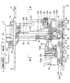
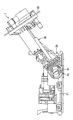
- FIG. 3 is a cross-sectional view showing a fuel supply device according to an embodiment, and is a cross-sectional view taken along line III-III in FIG. 1.
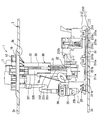
- FIG. 4 is a cross-sectional view showing a fuel supply device according to an embodiment, and is a cross-sectional view taken along line IV-IV in FIG. 3.
- a fuel supply device 1 is applied to an internal combustion engine 3 of a vehicle by being mounted on a fuel tank 2.
- the fuel supply device 1 supplies the fuel stored in the fuel tank 2 in the vehicle to the internal combustion engine 3 outside the fuel tank 2.
- the fuel tank 2 is formed of resin or metal and has a hollow shape as a whole.
- An insertion hole 2 b passes through the upper wall 2 a of the fuel tank 2.
- the fuel supply device 1 is inserted into the fuel tank 2 through the insertion hole 2b.
- the internal combustion engine 3 that is the fuel supply destination from the fuel supply device 1 may be a gasoline engine or a diesel engine. 1 and 2 showing the state of the fuel supply device 1 inserted into the fuel tank 2, the vertical direction and the horizontal direction substantially coincide with the vertical direction and horizontal direction of the vehicle on the horizontal plane, respectively.
- the fuel supply device 1 is constructed including a lid body 10, a pump unit 20, and a connecting column 30.
- the lid 10 is made of resin and has a disk shape.
- the lid 10 is attached to the upper wall 2 a of the fuel tank 2. With this attachment, the lid body 10 closes the insertion hole 2b.
- the lid 10 integrally includes a fuel supply pipe 11 and an electrical connector 12.
- the fuel supply pipe 11 communicates with the pump unit 20 in the fuel tank 2. As shown in FIG. 1, the fuel supply pipe 11 communicates with the fuel path 4 between the fuel tank 2 and the internal combustion engine 3 outside the fuel tank 2. Under such a communication state, the pump unit 20 discharges the fuel in the fuel tank 2 toward the internal combustion engine 3 outside the fuel tank 2, so that the discharged fuel is sent from the fuel supply pipe 11 to the internal combustion engine 3 through the fuel path 4. Supplied.
- the electrical connector 12 includes a plurality of metal terminals 12a. Each metal terminal 12 a is electrically connected to the fuel pump 22 of the pump unit 20 in the fuel tank 2. Each metal terminal 12 a is electrically connected to a control circuit system 5 such as an ECU outside the fuel tank 2. Under such an electrical connection state, the fuel pump 22 is controlled in accordance with a control signal sent from the control circuit system 5 through each metal terminal 12a.
- a control circuit system 5 such as an ECU outside the fuel tank 2.
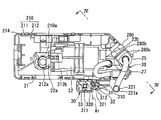
- the pump unit 20 is accommodated in the fuel tank 2 below the lid 10. As shown in FIGS. 1 to 4, the pump unit 20 includes a unit main body 21, a fuel pump 22, a passage member 25, and a pressure regulator 26.
- the unit main body 21 has a flat rectangular box shape as a whole.
- the unit main body 21 is placed on the bottom wall 2 c of the fuel tank 2.
- the unit main body 21 is provided with a sub tank 210 and a filter screen 214.
- the sub tank 210 is configured by combining a lower member 211 and an upper member 212.
- the lower member 211 is made of resin and has a flat plate shape.
- the lower member 211 has a plurality of inflow holes 211a penetrating in the vertical direction. From the lower member 211, a plurality of protrusions 211b protrude downward. Each protrusion 211b ensures an inflow gap 2d between the lower member 211 and the bottom wall 2c by contacting the bottom wall 2c of the fuel tank 2 from above. The fuel in the fuel tank 2 flows into each inflow hole 211a through this inflow gap 2d.
- the upper member 212 is made of resin and has an inverted cup shape.
- the outer peripheral edge portion of the upper member 212 is fixed to the outer peripheral edge portion of the lower member 211, thereby forming a storage space 210 a of the sub tank 210 in cooperation with the lower member 211.
- the upper member 212 is provided with a through hole 212a so as to penetrate in the vertical direction. The fuel in the fuel tank 2 flows into the upper member 212 through the through hole 212a, and is stored in the storage space 210a of the sub tank 210.
- the filter screen 214 shown in FIGS. 1 to 3 is formed of a material that exhibits a filtering function, such as porous resin, woven fabric, non-woven fabric, resin mesh, and metal mesh.
- the filter screen 214 has a flat rectangular bag shape, and an outer peripheral edge portion is sandwiched between the lower member 211 and the upper member 212. In such a sandwiched state, the inflow fuel from the fuel tank 2 into the inflow holes 211 a and the upper member 212 is filtered through the filter screen 214. The filtered fuel is sucked into the fuel pump 22 from the filter screen 214.
- the fuel pump 22 is an electric pump such as a vane pump or a trochoid pump.
- the fuel pump 22 has a cylindrical shape facing in the lateral direction.
- the fuel pump 22 is held on the upper part 212 b of the upper member 212 in the unit main body 21.
- the fuel pump 22 is electrically connected to each metal terminal 12a through a flexible wiring that can be bent.
- the suction port 22a of the fuel pump 22 communicates with the filter screen 214 while being inserted into the upper member 212 through the through hole 212a.
- the discharge port 22b of the fuel pump 22 communicates with the fuel supply pipe 11 through the fuel flow passage 25a of the passage member 25 and the communication passage 221a of the flexible tube 221 that can be bent.
- the fuel pump 22 is driven according to a control signal from the control circuit system 5 to suck in the filtered fuel in the filter screen 214.
- the fuel pump 22 discharges the fuel thus sucked into the fuel flow passage 25a toward the internal combustion engine 3.
- the passage member 25 is configured by combining two resin materials, and has a hollow shape as a whole.
- the passage member 25 is held by the upper part 212 b of the upper member 212 in the unit main body 21.
- the passage member 25 forms a fuel flow passage 25a inside.
- the fuel flow passage 25a allows the fuel discharged from the fuel pump 22 to flow from the fuel pump 22 toward the internal combustion engine 3 by communicating between the discharge port 22b and the communication passage 221a.
- the pressure regulator 26 is a diaphragm type fuel pressure adjustment valve.
- the pressure regulator 26 is held on the upper part 212 b of the upper member 212 of the unit main body 21 via the passage member 25.
- the pressure regulator 26 is provided with an inlet portion 27 and an outlet portion 28.
- the inlet portion 27 forms a branch passage 27a that branches from a middle portion of the fuel flow passage 25a.
- the outlet portion 28 forms a discharge passage 28 a that communicates with the storage space 210 a of the sub tank 210 through the upper member 212.
- a part of the fuel flowing through the fuel flow passage 25a branches to the branch passage 27a according to the consumed flow rate of the consumed fuel.
- the branch fuel to the branch passage 27a is controlled by the valve opening drive of the pressure regulator 26 for the branch flow rate returned to the storage space 210a by the discharge through the discharge passage 28a.
- the fuel pressure in the fuel flow passage 25a is adjusted to a pressure corresponding to the consumption flow rate in the internal combustion engine 3.
- the connecting column 30 is accommodated in the fuel tank 2.
- pillar 30 has connected independently between the cover body 10 and the pump unit 20 as a whole.
- the pump unit 20 is mounted on the single connecting column 30 so as to be rotatable around the rotation axis Ar along the lateral direction.
- the rotation position around the rotation axis Ar with respect to the connecting column 30 is defined in the pump unit 20 as a use rotation position Ru shown in FIGS. 1 and 2 and an insertion rotation position Ri shown in FIG.
- the use rotation position Ru corresponds to the unit main body 21 with respect to the connecting column 30 that extends in the longitudinal direction as a whole under the insertion state of the fuel supply device 1 into the fuel tank 2 as shown in FIGS. Is a rotational position in which it is bent at a substantially right angle and placed on the bottom wall 2c.
- the insertion rotation position Ri is a rotation position at which the bending of the unit main body 21 with respect to the connecting column 30 is reduced from the use rotation position Ru before the fuel supply device 1 is inserted into the fuel tank 2 as shown in FIG. At the insertion rotation position Ri, the entire fuel supply device 1 can be inserted into the fuel tank 2 through the insertion hole 2b from the pump unit 20 side.
- the connecting column 30 includes a lower column 31, an upper column 32, and an urging spring 33.
- the lower column 31 is configured by combining a rotating plate part 310, a lower column part 311, and a lower cylinder part 312.
- the rotating plate portion 310 is made of resin and has a flat plate shape that extends in the vertical direction and the horizontal direction.
- the rotating plate portion 310 is attached to the side portion 212c of the upper member 212 in the unit main body portion 21 so as to be rotatable around the rotation axis Ar.
- the lower column portion 311 is formed of resin and has a rectangular column shape along the vertical direction.
- the lower cylinder portion 312 is made of resin and has a rectangular cylinder shape along the vertical direction.
- the upper support column 32 is configured by combining the upper tube portion 320 and the upper column portion 321.
- the upper cylinder part 320 is formed of resin and has a rectangular cylinder shape along the vertical direction.
- the upper cylinder part 320 extends downward from the lid body 10.
- a lower column portion 311 is slidably fitted from below.
- the upper column part 321 is made of resin and has a rectangular column shape along the vertical direction.
- the upper column part 321 extends downward from the lid body 10.
- the upper column part 321 is slidably fitted into the lower cylinder part 312 from above.
- the urging spring 33 is made of metal and has a coil spring shape.
- the urging spring 33 is accommodated between the upper cylinder part 320 and the lower column part 311 so as to be sandwiched between the upper cylinder part 320 and the lower column part 311.
- the urging spring 33 causes the lower column part 311 to have a restoring force directed downward while being locked by the upper cylinder part 320. With this restoring force, each protrusion 211 b of the unit main body 21 is pressed against the bottom wall 2 c in the fuel tank 2. As a result, the relative position between the lower support column 31 and the upper support column 32 changes according to the expansion / contraction of the fuel tank 2, so that the connection support column 30 is prevented from being damaged.
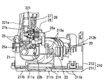
- the inlet 27 of the pressure regulator 26 includes a fixed cover 270, a fixed holder 271, a valve seat plate 272, a diaphragm 273, a movable holder 274, and a valve body nozzle 275.
- the fixed cover 270 is made of metal and has a stepped cylindrical shape facing in the horizontal direction.
- the small-diameter portion 270 b enters the passage member 25 with the large-diameter portion 270 a fitted and fixed to the passage member 25 via the rubber O-ring 276.
- the flange 270c formed by the large-diameter portion 270a at the edge opposite to the small-diameter portion 270b has an annular plate shape substantially perpendicular to the lateral direction.
- an inflow port 270e penetrates the step 270d connecting the large diameter portion 270a and the small diameter portion 270b in the lateral direction.
- the branch passage 27a formed in the large diameter portion 270a communicates with the fuel flow passage 25a through the inflow port 270e. According to such a communication mode, branched fuel branched from the fuel flow passage 25a (hereinafter, also simply referred to as “branched fuel”) flows into the branch passage 27a.
- the fixed holder 271 is made of metal and has a stepped columnar shape facing in the horizontal direction.
- the fixed holder 271 enters the branch passage 27a while being fitted and fixed to the small diameter portion 270b of the fixed cover 270.
- the valve seat plate 272 is made of metal and has a disk shape substantially perpendicular to the lateral direction.
- the valve seat plate 272 is coaxially mounted on the fixed holder 271 via a ball-shaped joint 277. With this mounting configuration, the valve seat plate 272 can tilt within a predetermined angle range while being accommodated in the branch passage 27a.
- the valve seat plate 272 has a flat valve seat surface 272 a extending in the vertical and horizontal directions on the side opposite to the fixed holder 271.
- the diaphragm 273 is formed of a composite material of rubber and a base cloth, and has an annular film shape that partitions the inlet portion 27 and the outlet portion 28 in the lateral direction.
- the diaphragm 273 is flexible and elastically deformable.
- the outer peripheral edge portion of the diaphragm 273 is caulked and fixed coaxially by the flange 270 c of the fixed cover 270.
- the diaphragm 273 is exposed to the branch passage 27 a on the side opposite to the outlet portion 28.
- the diaphragm 273 corresponds to a “partition body”.
- the movable holder 274 is made of metal and has an annular plate shape that faces in the lateral direction.
- the movable holder 274 is coaxially mounted on the inner peripheral edge of the diaphragm 273.
- the movable holder 274 supported by the diaphragm 273 can reciprocate in the axial direction (that is, the lateral direction in FIG. 6) while being coaxially exposed in the branch passage 27a.
- the valve body nozzle 275 is made of metal and has a cylindrical shape facing in the lateral direction.
- the valve body nozzle 275 is coaxially mounted on the inner peripheral portion of the movable holder 274.
- the valve element nozzle 275 supported by the diaphragm 273 can reciprocate in the axial direction (that is, the lateral direction in FIG. 6) while being coaxially projected into the branch passage 27a.
- the valve body nozzle 275 has a cylindrical hole-shaped nozzle passage 275a that opens toward the valve seat plate 272 side.
- the valve body nozzle 275 realizes on-off valve driving to be separated from and seated on the valve seat surface 272a of the valve seat plate 272 by reciprocating movement. Specifically, the valve body nozzle 275 blocks between the branch passage 27a and the nozzle passage 275a in the valve-closing drive seated on the valve seat surface 272a.
- the valve body nozzle 275 causes the branch passage 27a and the nozzle passage 275a to communicate with each other in the valve opening drive in which the valve body surface 272a is separated from the valve seat surface 272a.
- the outlet portion 28 of the pressure regulator 26 with respect to the inlet portion 27 includes an outer cover 280, a discharge pipe 281, an inner cover 282, a spring receiver 283, and an adjustment spring 284.
- the outer cover 280 is made of resin and has a bottomed cylindrical shape facing in the horizontal direction.
- the outer cover 280 covers the inner cover 282, so that a fuel space 280a is formed between the outer cover 280 and the inner cover 282.
- a pair of fixing portions 280c protruding from the peripheral wall 280b toward the inlet portion 27 are fitted and fixed to the passage member 25 by snap fitting.
- the peripheral wall 280b is in coaxial contact with the portion 270f of the flange 270c of the fixed cover 270 shown in FIG. 6 where the diaphragm 273 is caulked and fixed, on the opposite side to the bottom wall 280d. . That is, in the present embodiment, the flange 270c of the fixed cover 270 corresponds to the “contact wall”.
- the discharge pipe 281 is integrally formed with the bottom wall 280d of the outer cover 280 with resin.
- the discharge pipe 281 has an L-shaped cylindrical shape that is bent and extended in the vertical direction from the horizontal direction.
- the discharge pipe 281 has a discharge passage 28a that is located coaxially with the nozzle passage 275a in the laterally extending portion and communicates with the fuel space 280a.
- the discharge pipe 281 has an internal discharge passage 28 a opened downward toward the storage space 210 a of the sub tank 210 in the longitudinally extending portion.
- the opening-shaped discharge passage 28a can discharge the branched fuel from the fuel space 280a and return it to the storage space 210a.
- the inner cover 282 is made of metal and has a bottomed cylindrical shape facing in the horizontal direction.
- the inner cover 282 has an outer diameter that is smaller than the inner diameter of the outer cover 280 and an axial length that is shorter than the outer cover 280.
- the inner cover 282 is accommodated coaxially within the outer cover 280.
- the flange 282 c formed by the peripheral wall 282 b on the side opposite to the bottom wall 282 d is caulked and fixed by a caulking fixing portion 270 f of the flange 270 c of the fixed cover 270.
- a diaphragm 273 is exposed on the side opposite to the valve seat plate 272 in an inner space 282 a formed with a peripheral wall 282 b inside.
- the valve body nozzle 275 protrudes coaxially into the inner space 282a, and the nozzle passage 275a communicates with the valve seat plate 272 on the opposite side.
- the peripheral wall 282b that surrounds the valve body nozzle 275 from the radially outer side in the inner cover 282 has a radial gap 280ar that functions as a part of the fuel space 280a, and the peripheral wall 280b of the outer cover 280 that is radially outward. And formed between.
- the bottom wall 282d surrounded by the peripheral wall 282b from the outside in the radial direction in the inner cover 282 has an axial gap 280aa that functions as the remaining portion of the fuel space 280a with the bottom wall 280d of the outer cover 280 that faces the axial direction. Formed in between.
- a first series of through holes 285 are formed in a cylindrical hole shape at one location facing the valve body nozzle 275 in the axial direction.
- the first through hole 285 passes through the bottom wall 282d in the axial direction (that is, in the lateral direction in FIG. 6).
- the first through hole 285 has a larger inner diameter than the nozzle passage 275a located on the same axis, so that negative pressure can be generated in the inner space 282a described in detail later.
- the inner space 282a communicates with the axial gap 280aa in the fuel space 280a through the first series of through holes 285.
- second communication holes 286 are respectively formed in a cylindrical hole shape at a plurality of positions shifted from the bottom wall 282d to the separation side that is separated in the axial direction.
- Each second communication hole 286 passes through the peripheral wall 282b in the radial direction (for example, the vertical direction enabling water drainage in FIG. 6), and is located on the outer side in the radial direction with respect to the first continuous hole 285. Yes.
- the inner diameter of each of the second communication holes 286 has a predetermined magnitude relationship according to the specification with respect to the inner diameter of the first communication hole 285.
- the inner space 282a communicates with the radial gap 280ar in the fuel space 280a through the second communication hole 286.
- the spring receiver 283 is made of metal and has an annular plate shape that faces in the lateral direction.
- the spring receiver 283 is coaxially attached to the outer periphery of the movable holder 274.
- the spring receiver 283 supported by the diaphragm 273 can reciprocate in the axial direction (that is, the lateral direction in FIG. 6) while being coaxially exposed in the inner space 282a.
- the adjustment spring 284 is made of metal and has a coil spring shape facing in the lateral direction.
- the adjustment spring 284 is accommodated coaxially in the inner space 282a.
- the adjustment spring 284 is sandwiched between the spring receiver 283 and the bottom wall 282d of the inner cover 282 in the axial direction (that is, the lateral direction in FIG. 6).
- the adjustment spring 284 applies a restoring force toward the seating side with the valve seat plate 272 to the valve body nozzle 275 while being locked by the inner cover 282.
- the valve opening drive for increasing the branch flow rate of the branched fuel branched from the fuel flow passage 25a to the branch passage 27a of the inlet portion 27 as the consumption flow rate in the internal combustion engine 3 decreases. Is required. Accordingly, the pressure regulator 26 opens the valve body nozzle 275 in the axial direction against the restoring force of the adjustment spring 284 by the positive pressure action from the branched fuel flowing into the branched passage 27a, thereby causing the branched fuel to flow. It is ejected to the inner space 282a of the outlet portion 28.
- the pressure regulator 26 As a result, as the branch flow rate of the branched fuel increases, the pressure regulator 26 generates a negative pressure in the inner space 282a that increases the differential pressure from the atmospheric pressure. As a result, when a negative pressure following the increase in the branch flow rate acts on the diaphragm 273, the valve element nozzle 275 is further driven to open in the axial direction against the restoring force of the adjustment spring 284. Therefore, as the branch flow rate increases, the valve-opening drive of the valve body nozzle 275 is assisted and more branch fuel is discharged from the inner space 282a and the fuel space 280a to the discharge passage 28a. Therefore, the fuel flow passage 25a is adjusted. The increase in fuel pressure is suppressed.
- the adjustment spring 284 corresponds to an “elastic member”.
- the positive pressure is applied from the branched fuel flowing into the branch passage 27a, whereby the flange 270c of the fixed cover 270 is biased toward the outlet portion 28 side.
- the outer cover 280 is biased toward the inlet portion 27 side by applying a negative pressure from the inner space 282a to the fuel space 280a through the communication holes 285 and 286. Due to the urging to both sides, the contact interface between the flange 270c and the outer cover 280 is sealed. Under such a seal contact state, the fuel space 280a and the inner space 282a are isolated from the outside of the outer cover 280 and are kept airtight.
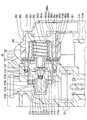
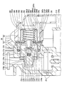
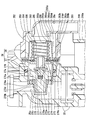
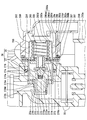
- the outer cover 280 covers the inner cover 282 in which the adjustment spring 284 is accommodated in the inner space 282a for applying a negative pressure to the diaphragm 273 to form the communication holes 285 and 286.
- the fuel space 280a formed between the covers 280 and 282 includes a first communication hole 285 that is axially opposed to the valve body nozzle 275, and a second communication hole 286 that is radially outside of the first communication hole 285. By communicating with the inner space 282a, the negative pressure is applied.
- the branched fuel jetted from the valve element nozzle 275 is sucked into the fuel space 280a through the first through hole 285 located at the jet destination. Then, a part of the branched fuel is discharged from the outer cover 280, but the branched fuel that has not been discharged is sucked into the inner space 282a through the second communication hole 286 on the radially outer side. Since the branched fuel until it is discharged from the outer cover 280 can be circulated between the inner space 282a and the fuel space 280a, it does not easily stay in the outlet portion 28. Therefore, it is possible to prevent the two covers 280, 282 and the adjustment spring 284 from corroding or deteriorating due to the property change of the branched fuel staying at the outlet portion 28, so that durability can be ensured. It becomes.
- the second communication hole 286 is formed in the peripheral wall 282b surrounding the valve body nozzle 275 from the outer side in the radial direction, while the peripheral wall 282b surrounds the second communication hole 286 from the outer side in the radial direction.
- a first through hole 285 is formed in the bottom wall 282d.
- the second communication hole 286 is formed in the peripheral wall 282b that is shifted from the bottom wall 282d to the axially separated side.
- branch fuel can be circulated from the radial gap 280ar between the outer cover 280 and the peripheral wall 282b to the inner space 282a through the second communication hole 286 spaced from the bottom wall 282d. It can be avoided in the widest possible area of 280ar. Therefore, it is possible to reliably suppress the corrosion or deterioration of both covers 280 and 282 due to the change in the properties of the branched fuel staying in the radial gap 280ar, and to increase the reliability of securing the durability.
- the outer cover 280 urged toward the inlet portion 27 side by negative pressure in the outlet portion 28 of the present embodiment is a flange urged toward the outlet portion 28 side due to the positive pressure of the branched fuel in the inlet portion 27. 270c is in sealing contact.
- the outer cover 280 can keep the fuel space 280a and the inner space 282a airtight even if no seal member is provided between the outer cover 280 and the flange 270c. Therefore, the circulating action of circulating the branched fuel from the fuel space 280a to the inner space 282a by negative pressure suction can be surely exerted even under a simple configuration without a seal member, and the reliability of ensuring durability can be increased. Become.
- the second communication hole 286 is formed in the corner portion 282e formed by the peripheral wall 282b and the bottom wall 282d on the outer side in the radial direction from the first series of communication holes 285. May be formed.
- a second communication hole 286 may be formed at a location on the bottom wall 282 d that is radially outward from the first serial hole 285.
- a seal such as a rubber O-ring is provided between the peripheral wall 280b of the outer cover 280 and the caulking fixing portion 270f of the flange 270c of the fixing cover 270 as shown in FIGS.
- the member 287 may be clamped in the axial direction.
- a seal member 288 such as a rubber O-ring is provided between the peripheral wall 280 b of the outer cover 280 and the peripheral wall 282 b of the inner cover 282 in the axial direction. It may be pinched.
- a fifth modified example as shown in FIG.
- the peripheral wall 282 b of the inner cover 282 is press-fitted into the press-fit portion 280 e of the peripheral wall 280 b of the outer cover 280, so May be.
- the fuel space 280a and the inner space 282a are not connected to the outside of the outer cover 280 regardless of whether or not the outer cover 280 is in sealing contact with the flange 270c as a “contact wall”. It will be isolated and kept airtight.
- a discharge pipe 281 may be formed in a cylindrical shape facing the horizontal direction in the outlet portion 28 as shown in FIG.
- the discharge passage 28 a that is formed coaxially with the nozzle passage 275 a inside the discharge pipe 281 and communicates with the fuel space 280 a faces the storage space 210 a of the sub tank 210. Thus, it is opened in the axial direction (that is, the lateral direction in FIG. 13).
- the components 270 to 275 of the inlet portion 27 and the components 280 to 284 of the outlet portion 28 may be arranged with their axial directions along the vertical direction.
- the function of the adjustment spring 284 may be achieved by various “elastic members” such as a spring having a shape other than the coil spring shape or a rubber member having a predetermined shape.
- the valve body nozzle 275 is driven to close, and the fuel pressure discharged from the fuel pump 22 is checked when the pressure sensor for detecting the fuel pressure in the fuel flow passage 25a is checked. May be temporarily raised and the valve body nozzle 275 may be driven to open. Also in the case of Modification 9, the fuel pressure in the fuel flow passage 25a is adjusted by the valve-opening drive of the valve body nozzle 275.
- a piston 1273 that exhibits the function of a “partition body” may be employed instead of the diaphragm 273.
- the cylindrical piston 1273 is supported by the large diameter portion 270a of the fixed cover 270 so as to be slidable in the axial direction, so that the inlet portion 27 and the outlet portion 28 are partitioned.
- the valve body nozzle 275 is mounted on the inner peripheral portion of the piston 1273 via the movable holder 274 so that the valve body nozzle 275 is supported by the piston 1273 so as to be capable of reciprocating in the axial direction (that is, the lateral direction in FIG. 14). Yes.
Landscapes
- Engineering & Computer Science (AREA)
- General Engineering & Computer Science (AREA)
- Mechanical Engineering (AREA)
- Chemical & Material Sciences (AREA)
- Combustion & Propulsion (AREA)
- Fuel-Injection Apparatus (AREA)
Abstract
プレッシャレギュレータ(26)では、インレット部(27)とアウトレット部(28)とを仕切るダイヤフラム(273)に弁体ノズル(275)が支持され、燃料流通路(25a)からインレット部(27)への分岐燃料が弁体ノズル(275)を通してアウトレット部(28)に噴出されることで、調整スプリング(284)に抗して弁体ノズル(275)が開弁駆動される。アウトレット部(28)は、負圧をダイヤフラム(273)に作用させる内側空間(282a)に調整スプリング(284)が収容され、弁体ノズル(275)と対向させて第一連通孔(285)を形成し、第一連通孔(285)よりも径方向外側に第二連通孔(286)を形成の内カバー(282)と、内カバー(282)を覆うことで、連通孔(285,286)を通じて内側空間(282a)に連通の燃料空間(280a)を内カバー(282)との間に形成し、燃料空間(280a)から分岐燃料を排出させる外カバー(280)とを備える。
Description
本願は、2016年3月30日に出願された日本国特許出願第2016-69318号に基づくものであり、この開示をもってその内容を本明細書中に開示したものとする。
本開示は、プレッシャレギュレータ及び燃料供給装置に関する。
従来、広く知られている燃料供給装置には、内燃機関へ向かう燃料流通路に燃料を吐出する燃料ポンプと、当該燃料流通路において燃料圧力を調整するプレッシャレギュレータとが、設けられている。
こうした燃料供給装置のプレッシャレギュレータとして特許文献1には、インレット部とアウトレット部とを仕切る仕切体としてのダイヤフラムにより弁体ノズルを支持したものが、開示されている。このような構成では、燃料流通路からインレット部へ分岐した分岐燃料が弁体ノズルを通してアウトレット部に噴出されることで、ダイヤフラムに負圧が作用して弁体ノズルが弾性部材に抗した軸方向に開弁駆動される。故に、燃料流通路から分岐燃料の分岐流量が増加する際には、弁体ノズルの開弁駆動が負圧の利用によりアシストされることで、調整される燃料圧力の上昇が抑えられる。これによれば、燃料ポンプに掛かる負荷を下げて、燃費の向上を図ることが可能となる。
さて、特許文献1に開示のプレッシャレギュレータにおいてアウトレット部は、負圧をダイヤフラムに作用させる内側空間に弾性部材が収容されるカバーを、備えている。このカバーの内側空間からは、弁体ノズルから噴出された分岐燃料が排出される。しかし、カバーの内側空間のうち、弁体ノズルと軸方向に対向する対向箇所からは、噴出流に乗せて分岐燃料を排出できるが、当該対向箇所よりも径方向の外側では、分岐燃料が滞留してしまう。その結果としてカバーの内側空間では、滞留した分岐燃料が性状変化してカバーや弾性部材を腐食乃至は劣化等させることで、耐久性を低下させるおそれがあった。
本開示は、以上説明した問題に鑑みてなされたものであって、その目的は、耐久性の確保されるプレッシャレギュレータ及び燃料供給装置を、提供することにある。
上記の目的を達成するために、本開示の第一の態様では、
燃料ポンプから内燃機関へ向かう燃料流通路において燃料圧力を調整するプレッシャレギュレータとして、インレット部とアウトレット部とを仕切る仕切体により弁体ノズルが支持されており、燃料流通路からインレット部へ分岐した分岐燃料が弁体ノズルを通してアウトレット部に噴出されることにより、仕切体に負圧が作用して弾性部材に抗した軸方向に弁体ノズルが開弁駆動されるプレッシャレギュレータであって、
アウトレット部は、
負圧を仕切体に作用させる内側空間に弾性部材が収容されており、弁体ノズルと軸方向に対向させて第一連通孔を形成している一方、第一連通孔よりも径方向の外側に第二連通孔を形成している内カバーと、
内カバーを覆っていることにより、第一連通孔及び第二連通孔を通じて内側空間に連通する燃料空間を内カバーとの間に形成しており、燃料空間から分岐燃料を排出させる外カバーとを、
備えるプレッシャレギュレータを提供する。
燃料ポンプから内燃機関へ向かう燃料流通路において燃料圧力を調整するプレッシャレギュレータとして、インレット部とアウトレット部とを仕切る仕切体により弁体ノズルが支持されており、燃料流通路からインレット部へ分岐した分岐燃料が弁体ノズルを通してアウトレット部に噴出されることにより、仕切体に負圧が作用して弾性部材に抗した軸方向に弁体ノズルが開弁駆動されるプレッシャレギュレータであって、
アウトレット部は、
負圧を仕切体に作用させる内側空間に弾性部材が収容されており、弁体ノズルと軸方向に対向させて第一連通孔を形成している一方、第一連通孔よりも径方向の外側に第二連通孔を形成している内カバーと、
内カバーを覆っていることにより、第一連通孔及び第二連通孔を通じて内側空間に連通する燃料空間を内カバーとの間に形成しており、燃料空間から分岐燃料を排出させる外カバーとを、
備えるプレッシャレギュレータを提供する。
更に、上記の目的を達成するために、本開示の第二の態様では、
内燃機関へ向かう燃料流通路に燃料を吐出する燃料ポンプと、
燃料流通路において燃料圧力を調整するプレッシャレギュレータとして、インレット部とアウトレット部とを仕切る仕切体により弁体ノズルが支持されており、燃料流通路からインレット部へ分岐した分岐燃料が弁体ノズルを通してアウトレット部に噴出されることにより、仕切体に負圧が作用して弾性部材に抗した軸方向に弁体ノズルが開弁駆動されるプレッシャレギュレータとが、
設けられている燃料供給装置であって、
アウトレット部は、
負圧を仕切体に作用させる内側空間に弾性部材が収容されており、弁体ノズルと軸方向に対向させて第一連通孔を形成している一方、第一連通孔よりも径方向の外側に第二連通孔を形成している内カバーと、
内カバーを覆っていることにより、第一連通孔及び第二連通孔を通じて内側空間に連通する燃料空間を内カバーとの間に形成しており、燃料空間から分岐燃料を排出させる外カバーとを、
備える燃料供給装置を提供する。
内燃機関へ向かう燃料流通路に燃料を吐出する燃料ポンプと、
燃料流通路において燃料圧力を調整するプレッシャレギュレータとして、インレット部とアウトレット部とを仕切る仕切体により弁体ノズルが支持されており、燃料流通路からインレット部へ分岐した分岐燃料が弁体ノズルを通してアウトレット部に噴出されることにより、仕切体に負圧が作用して弾性部材に抗した軸方向に弁体ノズルが開弁駆動されるプレッシャレギュレータとが、
設けられている燃料供給装置であって、
アウトレット部は、
負圧を仕切体に作用させる内側空間に弾性部材が収容されており、弁体ノズルと軸方向に対向させて第一連通孔を形成している一方、第一連通孔よりも径方向の外側に第二連通孔を形成している内カバーと、
内カバーを覆っていることにより、第一連通孔及び第二連通孔を通じて内側空間に連通する燃料空間を内カバーとの間に形成しており、燃料空間から分岐燃料を排出させる外カバーとを、
備える燃料供給装置を提供する。
このような第一の態様及び第二の態様のアウトレット部では、負圧を仕切体に作用させる内側空間に弾性部材を収容して第一及び第二連通孔を形成している内カバーを、外カバーが覆っている。これにより、両カバー間に形成の燃料空間は、弁体ノズルと軸方向対向する第一連通孔と、第一連通孔よりも径方向外側の第二連通孔とを通じて、内カバーの内側空間に連通することで、負圧の作用を受けることとなる。その結果、弁体ノズルから噴出された分岐燃料は、当該噴出先に位置する第一連通孔を通じて燃料空間へと負圧吸引される。すると、分岐燃料の一部は外カバーから排出されるが、排出されなかった分岐燃料については、径方向外側の第二連通孔を通じて内側空間へと負圧吸引される。こうして外カバーから排出されるまでの分岐燃料は、内側空間と燃料空間との間で循環され得るので、アウトレット部には滞留し難くなる。故に、アウトレット部にて滞留した分岐燃料が性状変化するのに起因して両カバーや弾性部材が腐食乃至は劣化等するのを抑制できるので、耐久性を確保することが可能となる。
本開示についての上記目的およびその他の目的、特徴や利点は、添付の図面を参照しながら下記の詳細な記述により、より明確になる。
以下、本開示の一実施形態を図面に基づいて説明する。
図1に示すように、本開示の一実施形態による燃料供給装置1は、燃料タンク2に搭載されることで、車両の内燃機関3に適用される。燃料供給装置1は、車両において燃料タンク2内に貯留された燃料を、燃料タンク2外の内燃機関3へと供給する。ここで、図1,2に示すように燃料タンク2は、樹脂又は金属により形成され、全体として中空状を呈している。燃料タンク2の上壁2aには、挿入孔2bが貫通している。燃料供給装置1は、この挿入孔2bを通じて燃料タンク2内に挿入される。こうした挿入状態下、燃料供給装置1からの燃料供給先となる内燃機関3は、ガソリンエンジンであってもよいし、ディーゼルエンジンであってもよい。尚、燃料タンク2内への燃料供給装置1の挿入状態を示す図1,2において縦方向と横方向とはそれぞれ、水平面上における車両の鉛直方向と水平方向とに実質一致している。
(全体構成)
まず、燃料供給装置1の全体構成を説明する。燃料供給装置1は、蓋体10、ポンプユニット20及び連結支柱30を含んで構築されている。
まず、燃料供給装置1の全体構成を説明する。燃料供給装置1は、蓋体10、ポンプユニット20及び連結支柱30を含んで構築されている。
蓋体10は、樹脂により形成され、円板状を呈している。蓋体10は、燃料タンク2の上壁2aに取り付けられる。かかる取り付けにより蓋体10は、挿入孔2bを閉塞する。蓋体10は、燃料供給管11及び電気コネクタ12を一体に有している。燃料供給管11は、燃料タンク2内においてポンプユニット20に連通している。図1に示すように燃料供給管11は、燃料タンク2外において内燃機関3との間の燃料経路4に連通する。こうした連通状態下、ポンプユニット20が燃料タンク2内の燃料を燃料タンク2外の内燃機関3へと向けて吐出することで、当該吐出燃料が燃料供給管11から燃料経路4を通じて内燃機関3に供給される。
電気コネクタ12は、複数の金属ターミナル12aを内包している。各金属ターミナル12aは、燃料タンク2内においてポンプユニット20の燃料ポンプ22に電気接続されている。各金属ターミナル12aは、燃料タンク2外においてECU等の制御回路系5に電気接続される。こうした電気接続状態下、制御回路系5から各金属ターミナル12aを通じて送られる制御信号に従って、燃料ポンプ22が制御される。
ポンプユニット20は、燃料タンク2内において蓋体10の下方に収容されている。図1~4に示すようにポンプユニット20は、ユニット本体部21、燃料ポンプ22、通路部材25及びプレッシャレギュレータ26を備えている。ユニット本体部21は、全体として偏平した矩形箱状を、呈している。ユニット本体部21は、燃料タンク2の底壁2c上に載置される。ユニット本体部21には、サブタンク210及びフィルタスクリーン214が設けられている。
サブタンク210は、ロア部材211とアッパ部材212とを組み合わせて構成されている。ロア部材211は、樹脂により形成され、平板状を呈している。ロア部材211には、複数の流入孔211aが縦方向に貫通している。ロア部材211からは、複数の突部211bが下方へと向かって突出している。各突部211bは、燃料タンク2の底壁2cに上方から接触することで、ロア部材211と当該底壁2cとの間に流入隙間2dを確保する。燃料タンク2内の燃料は、この流入隙間2dを通じて各流入孔211aへと流入する。
アッパ部材212は、樹脂により形成され、逆カップ状を呈している。アッパ部材212の外周縁部は、ロア部材211の外周縁部に固定されることで、当該ロア部材211と共同してサブタンク210の貯留空間210aを形成している。アッパ部材212には、縦方向に貫通するように貫通孔212aが設けられている。燃料タンク2内の燃料は、この貫通孔212aを通じてアッパ部材212内へと流入することで、サブタンク210の貯留空間210aに貯留される。
図1~3に示すフィルタスクリーン214は、例えば多孔質樹脂、織布、不織布、樹脂メッシュ及び金属メッシュ等の濾過機能を発揮する素材により、形成されている。フィルタスクリーン214は、偏平した矩形袋状を呈し、ロア部材211とアッパ部材212との間に外周縁部を挟持されている。こうした挟持状態下、燃料タンク2内から各流入孔211a及びアッパ部材212内への流入燃料は、フィルタスクリーン214を通して濾過される。こうして濾過された燃料は、フィルタスクリーン214内から燃料ポンプ22に吸入される。
燃料ポンプ22は、例えばベーンポンプ又はトロコイドポンプ等の電動ポンプである。燃料ポンプ22は、横方向を向く円柱状を呈している。燃料ポンプ22は、ユニット本体部21のうちアッパ部材212の上部212bに、保持されている。燃料ポンプ22は、湾曲自在なフレキシブル配線を介して、各金属ターミナル12aと電気接続されている。燃料ポンプ22の吸入口22aは、貫通孔212aを通じてアッパ部材212内に挿入された状態下、フィルタスクリーン214内に連通している。燃料ポンプ22の吐出口22bは、通路部材25の燃料流通路25a及び湾曲自在なフレキシブルチューブ221の連通路221aを通じて、燃料供給管11に連通している。燃料ポンプ22は、制御回路系5からの制御信号に従って駆動することで、フィルタスクリーン214内の濾過された燃料を吸入する。燃料ポンプ22は、こうして吸入した燃料を、内燃機関3へと向かう燃料流通路25aに吐出する。
通路部材25は、二つの樹脂材を組み合わせて構成され、全体として中空状を呈している。通路部材25は、ユニット本体部21のうちアッパ部材212の上部212bに、保持されている。通路部材25は、燃料流通路25aを内部に形成している。燃料流通路25aは、吐出口22bと連通路221aとの間を連通することで、燃料ポンプ22からの吐出燃料を燃料ポンプ22から内燃機関3へ向かって流通させることが可能となっている。
プレッシャレギュレータ26は、ダイヤフラム式の燃料圧力調整バルブである。プレッシャレギュレータ26は、ユニット本体部21のうちアッパ部材212の上部212bに、通路部材25を介して保持されている。図4に示すようにプレッシャレギュレータ26には、インレット部27及びアウトレット部28が設けられている。インレット部27は、燃料流通路25aの中途部から分岐する分岐通路27aを、形成している。アウトレット部28は、アッパ部材212を通じてサブタンク210の貯留空間210aに連通する排出通路28aを、形成している。
こうしたプレッシャレギュレータ26では、内燃機関3の通常運転中は消費される燃料の消費流量に応じて、燃料流通路25aを流通する燃料の一部が分岐通路27aへと分岐する。このとき分岐通路27aへの分岐燃料は、排出通路28aを通した排出により貯留空間210aへとリターンされる分岐流量につき、プレッシャレギュレータ26の開弁駆動によって制御される。その結果、燃料流通路25aにおける燃料圧力は、内燃機関3での消費流量に応じた圧力に調整されることとなる。
図1に示すように連結支柱30は、燃料タンク2内に収容されている。連結支柱30は、蓋体10とポンプユニット20との間を、全体として単独で連結している。ここで単独の連結支柱30には、横方向に沿う回転軸線Arまわりに回転可能となるように、ポンプユニット20が装着されている。こうした装着状態下、連結支柱30に対する回転軸線Arまわりの回転位置としてポンプユニット20には、図1,2に示す使用回転位置Ruと、図5に示す挿入回転位置Riとが規定されている。
具体的に使用回転位置Ruは、図1,2の如き燃料タンク2内への燃料供給装置1の挿入状態下、全体として縦方向に延伸することになる連結支柱30に対し、ユニット本体部21が略直角に折り曲げられて底壁2c上に載置される回転位置である。一方で挿入回転位置Riは、図5の如き燃料タンク2内への燃料供給装置1の挿入前において、連結支柱30に対するユニット本体部21の折り曲げが使用回転位置Ruより減らされる回転位置である。かかる挿入回転位置Riでは、ポンプユニット20側から燃料供給装置1の全体を、挿入孔2bを通じて燃料タンク2内へ挿入可能となる。
図1~3に示すように連結支柱30は、ロア支柱31、アッパ支柱32及び付勢スプリング33を備えている。ロア支柱31は、回転板部310とロア柱部311とロア筒部312とを組み合わせて構成されている。回転板部310は、樹脂により形成され、縦方向且つ横方向に広がる平板状を呈している。回転板部310は、ユニット本体部21のうちアッパ部材212の側部212cに対して、回転軸線Arまわりに回転可能に装着されている。ロア柱部311は、樹脂により形成され、縦方向に沿う矩形柱状を呈している。ロア筒部312は、樹脂により形成され、縦方向に沿う矩形筒状を呈している。
アッパ支柱32は、アッパ筒部320とアッパ柱部321とを組み合わせて構成されている。アッパ筒部320は、樹脂により形成され、縦方向に沿う矩形筒状を呈している。アッパ筒部320は、蓋体10から下方に延伸している。アッパ筒部320内には、ロア柱部311が下方からスライド嵌合している。アッパ柱部321は、樹脂により形成され、縦方向に沿う矩形柱状を呈している。アッパ柱部321は、蓋体10から下方に延伸している。アッパ柱部321は、ロア筒部312内に上方からスライド嵌合している。
付勢スプリング33は、金属により形成され、コイルスプリング状を呈している。付勢スプリング33は、アッパ筒部320内とロア柱部311内とに跨って収容されることで、それらアッパ筒部320とロア柱部311との間に挟持されている。付勢スプリング33は、アッパ筒部320により係止された状態下、下方へ向かう復原力をロア柱部311に作用させる。かかる復原力によりユニット本体部21の各突部211bは、燃料タンク2内にて底壁2cに押し付けられる。その結果、ロア支柱31とアッパ支柱32との相対位置が燃料タンク2の膨縮に応じて変化することで、連結支柱30の破損が抑制される。
(プレッシャレギュレータの詳細構成)
次に、プレッシャレギュレータ26の詳細構成を説明する。
次に、プレッシャレギュレータ26の詳細構成を説明する。
図6に示すように、プレッシャレギュレータ26のインレット部27は、固定カバー270、固定ホルダ271、弁座プレート272、ダイヤフラム273、可動ホルダ274及び弁体ノズル275を備えている。
固定カバー270は、金属により形成され、横方向を向く段付円筒状を呈している。固定カバー270では、ゴム製Oリング276を介して大径部270aが通路部材25に嵌合固定された状態下、小径部270bが通路部材25内に突入している。固定カバー270において、大径部270aが小径部270bとは反対側縁部に形成しているフランジ270cは、横方向に対して実質垂直な円環板状を呈している。固定カバー270において、大径部270a及び小径部270bの間を接続している段差部270dには、流入口270eが横方向に貫通している。固定カバー270において、大径部270aが内部に形成している分岐通路27aは、流入口270eを通じて燃料流通路25aに連通している。かかる連通形態により分岐通路27aには、燃料流通路25aから分岐した分岐燃料(以下、単に「分岐燃料」ともいう)が流入する。
固定ホルダ271は、金属により形成され、横方向を向く段付円柱状を呈している。固定ホルダ271は、固定カバー270のうち小径部270bに嵌合固定された状態下、分岐通路27aに突入している。弁座プレート272は、金属により形成され、横方向に対して実質垂直な円板状を呈している。弁座プレート272は、ボール状の継ぎ手277を介して、固定ホルダ271に同軸上に装着されている。かかる装着形態により弁座プレート272は、分岐通路27aに収容された状態下、所定角度範囲内では傾動可能となっている。弁座プレート272は、縦方向且つ横方向に広がる平面状の弁座面272aを、固定ホルダ271とは反対側にて形成している。
ダイヤフラム273は、ゴムと基布との複合材により形成され、インレット部27とアウトレット部28とを横方向に仕切る円環膜状を呈している。ダイヤフラム273は、可撓性を与えられて弾性変形可能となっている。ダイヤフラム273の外周縁部は、固定カバー270のフランジ270cによって同軸上にカシメ固定されている。ダイヤフラム273は、アウトレット部28とは反対側にて分岐通路27aに露出している。このような本実施形態では、ダイヤフラム273が「仕切体」に相当している。
可動ホルダ274は、金属により形成され、横方向を向く円環板状を呈している。可動ホルダ274は、ダイヤフラム273の内周縁部に同軸上に装着されている。こうしてダイヤフラム273により支持されている可動ホルダ274は、分岐通路27aに同軸上に露出した状態下、軸方向(即ち、図6では横方向)にて往復移動可能となっている。
弁体ノズル275は、金属により形成され、横方向を向く円筒状を呈している。弁体ノズル275は、可動ホルダ274の内周部に同軸上に装着されている。こうしてダイヤフラム273により支持されている弁体ノズル275は、分岐通路27aに同軸上に突入した状態下、軸方向(即ち、図6では横方向)にて往復移動可能となっている。
弁体ノズル275は、弁座プレート272側へ向かって開口した円筒孔状のノズル通路275aを、内部に形成している。弁体ノズル275は、弁座プレート272の弁座面272aに対して離着座する開閉弁駆動を、往復移動により実現する。具体的に弁体ノズル275は、弁座面272aに着座する閉弁駆動では、分岐通路27a及びノズル通路275aの間を遮断する。一方で弁体ノズル275は、弁座面272aから離座する開弁駆動では、分岐通路27a及びノズル通路275aの間を連通させる。
このようなインレット部27に対してプレッシャレギュレータ26のアウトレット部28は、外カバー280、排出パイプ281、内カバー282、スプリング受け283及び調整スプリング284を備えている。
外カバー280は、樹脂により形成され、横方向を向く有底円筒状を呈している。外カバー280は、内カバー282を覆っていることで、当該内カバー282との間に燃料空間280aを形成している。外カバー280において、図3に示すように周壁280bからインレット部27側へと突出している一対の固定部280cは、スナップフィットによって通路部材25に嵌合固定されている。外カバー280において周壁280bは、図6に示す固定カバー270のフランジ270cのうちダイヤフラム273をカシメ固定している部分270fに対し、底壁280dとは反対側にて同軸上に面接触している。即ち本実施形態では、固定カバー270のフランジ270cが「接触壁」に相当している。
排出パイプ281は、樹脂により外カバー280の底壁280dと一体形成されている。排出パイプ281は、横方向から縦方向に屈曲されて延伸するL字形円筒状を、呈している。排出パイプ281は、横方向の延伸部分ではノズル通路275aと同軸上に位置して燃料空間280aと連通する排出通路28aを、内部に形成している。排出パイプ281は、縦方向の延伸部分では内部の排出通路28aを、サブタンク210の貯留空間210aへと向かって下方に開口させている。かかる開口形態の排出通路28aは、燃料空間280aから分岐燃料を排出させて貯留空間210aへとリターン可能となっている。
内カバー282は、金属により形成され、横方向を向く有底円筒状を呈している。内カバー282は、外カバー280の内径よりも小さな外径と、外カバー280よりも短い軸方向長とを、有している。内カバー282は、外カバー280の内部に同軸上に収容されている。内カバー282において、周壁282bが底壁282dとは反対側にて形成しているフランジ282cは、固定カバー270のフランジ270cのうちカシメ固定部分270fによってカシメ固定されている。内カバー282において、周壁282bが内部に形成している内側空間282aには、ダイヤフラム273が弁座プレート272とは反対側にて露出している。それと共に内側空間282aには、弁体ノズル275が同軸上に突入してノズル通路275aが弁座プレート272とは反対側にて連通している。
こうした構造により、内カバー282において弁体ノズル275を径方向外側から囲んでいる周壁282bは、燃料空間280aの一部として機能する径方向隙間280arを、径方向外側にある外カバー280の周壁280bとの間に形成している。一方、内カバー282において周壁282bにより径方向外側から囲まれている底壁282dは、燃料空間280aの残部として機能する軸方向隙間280aaを、軸方向に対向した外カバー280の底壁280dとの間に形成している。
内カバー282における底壁282dのうち、弁体ノズル275と軸方向に対向した一箇所には、第一連通孔285が円筒孔状に形成されている。第一連通孔285は、底壁282dを軸方向(即ち、図6では横方向)に貫通している。第一連通孔285は、同軸上に位置するノズル通路275aよりも大きい内径を有することで、後に詳述する内側空間282aでの負圧の発生を可能にしている。燃料空間280aのうち軸方向隙間280aaには、こうした第一連通孔285を通じて内側空間282aが連通している。
一方、内カバー282における周壁282bのうち、底壁282dから軸方向に離間する離間側へとずれた複数箇所には、それぞれ第二連通孔286が円筒孔状に形成されている。各第二連通孔286は、周壁282bを径方向(例えば、図6では水抜きを可能にする縦方向)に貫通することで、第一連通孔285よりも径方向の外側に位置している。各第二連通孔286の内径は、第一連通孔285の内径に対して仕様に応じた所定の大小関係を、有している。燃料空間280aのうち径方向隙間280arには、こうした第二連通孔286を通じて内側空間282aが連通している。
スプリング受け283は、金属により形成され、横方向を向く円環板状を呈している。スプリング受け283は、可動ホルダ274の外周部に同軸上に装着されている。こうしてダイヤフラム273により支持されているスプリング受け283は、内側空間282aに同軸上に露出した状態下、軸方向(即ち、図6では横方向)にて往復移動可能となっている。
調整スプリング284は、金属により形成され、横方向を向くコイルスプリング状を呈している。調整スプリング284は、内側空間282aに同軸上に収容されている。調整スプリング284は、スプリング受け283と内カバー282の底壁282dとの間に、軸方向(即ち、図6では横方向)にて挟持されている。調整スプリング284は、内カバー282により係止された状態下、弁座プレート272との着座側へと向かう復原力を弁体ノズル275に作用させる。
ここまで説明の如きプレッシャレギュレータ26では、燃料流通路25aからインレット部27の分岐通路27aへと分岐させる分岐燃料の分岐流量を、内燃機関3での消費流量が減少するほど、増加させる開弁駆動が求められる。そこでプレッシャレギュレータ26は、分岐通路27aに流入した分岐燃料からの正圧作用により、弁体ノズル275を調整スプリング284の復原力に抗して軸方向に開弁駆動することで、当該分岐燃料をアウトレット部28の内側空間282aへと噴出させる。
その結果、分岐燃料の分岐流量が増加するほど、大気圧との差圧が増加する負圧を、プレッシャレギュレータ26が内側空間282aに発生させる。これにより、分岐流量の増加に追従した負圧がダイヤフラム273に作用すると、弁体ノズル275が調整スプリング284の復原力に抗した軸方向へとさらに開弁駆動される。故に分岐流量が増加するほど、弁体ノズル275の開弁駆動がアシストされて多くの分岐燃料が内側空間282a及び燃料空間280aから排出通路28aへと排出されるので、燃料流通路25aでは調整される燃料圧力の上昇が抑えられる。このように本実施形態では、調整スプリング284が「弾性部材」に相当している。
ここで開弁駆動時のインレット部27では、分岐通路27aに流入した分岐燃料から正圧が作用することで、固定カバー270のフランジ270cがアウトレット部28側へと付勢される。一方で開弁駆動時のアウトレット部28では、内側空間282aから燃料空間280aに連通孔285,286を通じて負圧が作用することで、外カバー280がインレット部27側へと付勢される。これら両側への付勢により、フランジ270cと外カバー280との接触界面はシールされた状態となる。こうしたシール接触状態下にて燃料空間280a及び内側空間282aは、外カバー280の外部とは隔離されて気密に保持されるのである。
以上説明したことから本実施形態では、以下の作用効果が発現する。本実施形態のアウトレット部28では、負圧をダイヤフラム273に作用させる内側空間282aに調整スプリング284を収容して連通孔285,286を形成している内カバー282を、外カバー280が覆っている。これにより、両カバー280,282間に形成の燃料空間280aは、弁体ノズル275と軸方向対向する第一連通孔285と、第一連通孔285より径方向外側の第二連通孔286とを通じて、内側空間282aに連通することで、負圧の作用を受けることとなる。その結果、弁体ノズル275から噴出された分岐燃料は、当該噴出先に位置する第一連通孔285を通じて燃料空間280aへと負圧吸引される。すると、分岐燃料の一部は外カバー280から排出されるが、排出されなかった分岐燃料については、径方向外側の第二連通孔286を通じて内側空間282aへと負圧吸引される。こうして外カバー280から排出されるまでの分岐燃料は、内側空間282aと燃料空間280aとの間で循環され得るので、アウトレット部28には滞留し難くなる。故に、アウトレット部28にて滞留した分岐燃料が性状変化するのに起因して両カバー280,282や調整スプリング284が腐食乃至は劣化等するのを抑制できるので、耐久性を確保することが可能となる。
また、本実施形態において有底筒状の内カバー282では、弁体ノズル275を径方向外側から囲む周壁282bに第二連通孔286が形成されている一方、当該周壁282bにより径方向外側から囲まれる底壁282dに第一連通孔285が形成されている。その結果、外カバー280及び底壁282d間にて第一連通孔285と連通した軸方向隙間280aaと、外カバー280及び周壁282b間にて第二連通孔286と連通した径方向隙間280arとは、燃料空間280aとして機能することになる。これによれば、弁体ノズル275と軸方向対向する第一連通孔285から隙間280aa,280arへと順次に負圧吸引された分岐燃料であっても、第二連通孔286を通じて内側空間282aに循環し得るので、当該径方向隙間280arには滞留し難くなる。故に、特に径方向隙間280arにて滞留した分岐燃料の性状変化による両カバー280,282の腐食乃至は劣化等を抑制して、耐久性を確保することが可能となる。
さらに、本実施形態の内カバー282では、周壁282bにおいて底壁282dから軸方向の離間側へとずれて、第二連通孔286が形成されている。これにより外カバー280及び周壁282b間の径方向隙間280arからは、底壁282dと離間した第二連通孔286を通じて分岐燃料を内側空間282aに循環させ得るので、分岐燃料の滞留を当該径方向隙間280arの可及的に広い領域にて回避できる。故に、特に径方向隙間280arにて滞留した分岐燃料の性状変化による両カバー280,282の腐食乃至は劣化等を確実に抑制して、耐久性確保の信頼度を高めることが可能となる。
またさらに、本実施形態のアウトレット部28において負圧によりインレット部27側へと付勢される外カバー280は、インレット部27において分岐燃料の正圧によりアウトレット部28側へと付勢されるフランジ270cにシール接触している。これにより外カバー280は、フランジ270cとの間にシール部材が設けられていなくても、燃料空間280a及び内側空間282aを気密に保持し得る。故に、負圧吸引によって分岐燃料を燃料空間280aから内側空間282aへ循環させる循環作用につき、シール部材のない簡素な構成下でも確実に発揮させて、耐久性確保の信頼度を高めることが可能となる。
(他の実施形態)
以上、本開示の一実施形態について説明したが、本開示は、当該実施形態に限定して解釈されるものではなく、本開示の要旨を逸脱しない範囲内において種々の実施形態に適用することができる。
以上、本開示の一実施形態について説明したが、本開示は、当該実施形態に限定して解釈されるものではなく、本開示の要旨を逸脱しない範囲内において種々の実施形態に適用することができる。
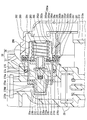
具体的に変形例1として、図7に示すように内カバー282では、第一連通孔285よりも径方向外側にて周壁282bが底壁282dとなす角部282eに、第二連通孔286が形成されていてもよい。変形例2として、図8に示すように内カバー282では、底壁282dのうち第一連通孔285よりも径方向外側となる箇所に、第二連通孔286が形成されていてもよい。
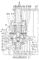
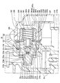
変形例3として、図9,10に示すようにアウトレット部28では、外カバー280の周壁280bと、固定カバー270のフランジ270cのうちカシメ固定部分270fとの間に、ゴム製Oリング等のシール部材287が軸方向にて挟持されていてもよい。変形例4として、図10,11に示すようにアウトレット部28では、外カバー280の周壁280bと、内カバー282の周壁282bとの間に、ゴム製Oリング等のシール部材288が軸方向にて挟持されていてもよい。変形例5として、図12に示すようにアウトレット部28では、外カバー280の周壁280bにおける圧入部280eに内カバー282の周壁282bが圧入されていることで、それら周壁280b,282bの間がシールされていてもよい。こうした変形例3~5の場合には、「接触壁」としてのフランジ270cに外カバー280がシール接触しているか否かに拘らず、燃料空間280a及び内側空間282aが外カバー280の外部とは隔離されて気密に保持されることとなる。
変形例6として、図13に示すようにアウトレット部28では、横方向を向く円筒状に、排出パイプ281が形成されていてもよい。かかる変形例6の場合には、排出パイプ281の内部にてノズル通路275aと同軸上に形成されることで燃料空間280aに連通している排出通路28aが、サブタンク210の貯留空間210aへと向かって軸方向(即ち、図13では横方向)に開口させられる。
変形例7としては、インレット部27の構成要素270~275及びアウトレット部28の構成要素280~284が、それぞれの軸方向を縦方向に沿わせて配置されていてもよい。変形例8としては、コイルスプリング状以外の形状のスプリング又は所定形状のゴム部材等といった各種の「弾性部材」により、調整スプリング284の機能が果たされていてもよい。
変形例9としては、内燃機関3の通常運転中は弁体ノズル275が閉弁駆動され、燃料流通路25aの燃料圧力を検出する圧力センサのチェック時等に、燃料ポンプ22から吐出の燃料圧力が一時的に高められて弁体ノズル275が開弁駆動されてもよい。かかる変形例9の場合にも、弁体ノズル275の開弁駆動により燃料流通路25aの燃料圧力が調整されることとなる。
変形例10としては、図14に示すように、「仕切体」の機能を発揮するピストン1273が、ダイヤフラム273の代わりに採用されていてもよい。かかる変形例10の場合には、固定カバー270の大径部270aにより円筒状のピストン1273が軸方向に往復摺動可能に支持されることで、インレット部27とアウトレット部28とが仕切られている。ここで弁体ノズル275は、ピストン1273の内周部に可動ホルダ274を介して装着されることで、当該ピストン1273によって軸方向(即ち、図14では横方向)に往復移動可能に支持されている。
Claims (5)
- 燃料ポンプ(22)から内燃機関(3)へ向かう燃料流通路(25a)において燃料圧力を調整するプレッシャレギュレータとして、インレット部(27)とアウトレット部(28)とを仕切る仕切体(273,1273)により弁体ノズル(275)が支持されており、前記燃料流通路(25a)から前記インレット部(27)へ分岐した分岐燃料が前記弁体ノズル(275)を通して前記アウトレット部(28)に噴出されることにより、前記仕切体(273,1273)に負圧が作用して弾性部材(284)に抗した軸方向に前記弁体ノズル(275)が開弁駆動されるプレッシャレギュレータであって、
前記アウトレット部(28)は、
前記負圧を前記仕切体(273,1273)に作用させる内側空間(282a)に前記弾性部材(284)が収容されており、前記弁体ノズル(275)と前記軸方向に対向させて第一連通孔(285)を形成している一方、前記第一連通孔(285)よりも径方向の外側に第二連通孔(286)を形成している内カバー(282)と、
前記内カバー(282)を覆っていることにより、前記第一連通孔(285)及び前記第二連通孔(286)を通じて前記内側空間(282a)に連通する燃料空間(280a)を前記内カバー(282)との間に形成しており、前記燃料空間(280a)から前記分岐燃料を排出させる外カバー(280)とを、
備えるプレッシャレギュレータ。 - 有底筒状の前記内カバー(282)は、
前記弁体ノズル(275)を前記径方向の外側から囲んで第二連通孔(286)を形成している周壁(282b)と、
前記周壁(282b)により前記径方向の外側から囲まれて前記第一連通孔(285)を形成している底壁(282d)とを、
有し、
前記外カバー(280)は、前記軸方向における前記底壁(282d)との間の隙間(280aa)と、前記径方向における前記周壁(282b)との間の隙間(280ar)とを、前記燃料空間(280a)として機能させている請求項1に記載のプレッシャレギュレータ。 - 前記第二連通孔(286)は、前記周壁(282b)において前記底壁(282d)から前記軸方向の離間側にずれて形成されている請求項2に記載のプレッシャレギュレータ。
- 前記インレット部(27)は、前記分岐燃料の正圧により前記アウトレット部(28)側へ付勢される接触壁(270c)を、備え、
前記アウトレット部(28)において前記外カバー(280)は、前記負圧により前記インレット部(27)側へ付勢されて前記接触壁(270c)にシール接触している請求項1~3のいずれか一項に記載のプレッシャレギュレータ。 - 内燃機関(3)へ向かう燃料流通路(25a)に燃料を吐出する燃料ポンプ(22)と、
前記燃料流通路(25a)において燃料圧力を調整するプレッシャレギュレータ(26)として、インレット部(27)とアウトレット部(28)とを仕切る仕切体(273,1273)により弁体ノズル(275)が支持されており、前記燃料流通路(25a)から前記インレット部(27)へ分岐した分岐燃料が前記弁体ノズル(275)を通して前記アウトレット部(28)に噴出されることにより、前記仕切体(273,1273)に負圧が作用して弾性部材(284)に抗した軸方向に前記弁体ノズル(275)が開弁駆動されるプレッシャレギュレータ(26)とが、
設けられている燃料供給装置であって、
前記アウトレット部(28)は、
前記負圧を前記仕切体(273,1273)に作用させる内側空間(282a)に前記弾性部材(284)が収容されており、前記弁体ノズル(275)と前記軸方向に対向させて第一連通孔(285)を形成している一方、前記第一連通孔(285)よりも径方向の外側に第二連通孔(286)を形成している内カバー(282)と、
前記内カバー(282)を覆っていることにより、前記第一連通孔(285)及び前記第二連通孔(286)を通じて前記内側空間(282a)に連通する燃料空間(280a)を前記内カバー(282)との間に形成しており、前記燃料空間(280a)から前記分岐燃料を排出させる外カバー(280)とを、
備える燃料供給装置。
Priority Applications (2)
| Application Number | Priority Date | Filing Date | Title |
|---|---|---|---|
| CN201780018045.3A CN108884797B (zh) | 2016-03-30 | 2017-03-06 | 压力调节器及燃料供给装置 |
| US16/077,849 US11193463B2 (en) | 2016-03-30 | 2017-03-06 | Pressure regulator and fuel supply device |
Applications Claiming Priority (2)
| Application Number | Priority Date | Filing Date | Title |
|---|---|---|---|
| JP2016069318A JP6387998B2 (ja) | 2016-03-30 | 2016-03-30 | プレッシャレギュレータ及び燃料供給装置 |
| JP2016-069318 | 2016-03-30 |
Publications (1)
| Publication Number | Publication Date |
|---|---|
| WO2017169530A1 true WO2017169530A1 (ja) | 2017-10-05 |
Family
ID=59964042
Family Applications (1)
| Application Number | Title | Priority Date | Filing Date |
|---|---|---|---|
| PCT/JP2017/008695 Ceased WO2017169530A1 (ja) | 2016-03-30 | 2017-03-06 | プレッシャレギュレータ及び燃料供給装置 |
Country Status (4)
| Country | Link |
|---|---|
| US (1) | US11193463B2 (ja) |
| JP (1) | JP6387998B2 (ja) |
| CN (1) | CN108884797B (ja) |
| WO (1) | WO2017169530A1 (ja) |
Families Citing this family (4)
| Publication number | Priority date | Publication date | Assignee | Title |
|---|---|---|---|---|
| JP6390681B2 (ja) * | 2016-03-14 | 2018-09-19 | 株式会社デンソー | 燃料供給装置 |
| JP6918733B2 (ja) * | 2018-03-28 | 2021-08-11 | 愛三工業株式会社 | 燃料タンク用蓋 |
| JP6968738B2 (ja) * | 2018-03-28 | 2021-11-17 | 愛三工業株式会社 | 燃料タンク用蓋 |
| JP7083734B2 (ja) * | 2018-10-15 | 2022-06-13 | 愛三工業株式会社 | 燃料供給装置 |
Citations (4)
| Publication number | Priority date | Publication date | Assignee | Title |
|---|---|---|---|---|
| JPS63170669U (ja) * | 1987-04-27 | 1988-11-07 | ||
| JP2003278618A (ja) * | 2002-03-26 | 2003-10-02 | Denso Corp | 燃料圧力調整弁 |
| US20130056098A1 (en) * | 2011-09-01 | 2013-03-07 | Continental Automotive Systems Us, Inc. | Compact fuel pressure regulator |
| JP2013174183A (ja) * | 2012-02-24 | 2013-09-05 | Aisan Industry Co Ltd | 燃料供給装置 |
Family Cites Families (14)
| Publication number | Priority date | Publication date | Assignee | Title |
|---|---|---|---|---|
| DE4336061B4 (de) | 1993-10-22 | 2005-03-03 | Siemens Ag | Druckbegrenzungsventil |
| DE4430472A1 (de) * | 1994-08-27 | 1996-02-29 | Bosch Gmbh Robert | Druckregelventil |
| US5873349A (en) | 1997-03-07 | 1999-02-23 | Walbro Corporation | Fuel pressure regulator |
| US5830348A (en) | 1997-03-17 | 1998-11-03 | Siemens Automotive Corporation | Fuel filter module with integral regulator |
| US6006781A (en) | 1998-07-01 | 1999-12-28 | Parr Manufacturing, Inc. | Fuel pressure regulator |
| US6293259B1 (en) | 1999-05-14 | 2001-09-25 | Siemens Automotive Corporation | Automotive fuel system having a pressure regulator without a movable diaphragm |
| US6286486B1 (en) | 1999-12-06 | 2001-09-11 | Siemens Automotive Corporation | Fuel system including a pressure regulator |
| US6318405B1 (en) | 2000-03-08 | 2001-11-20 | Mahle-Parr Filter Systems, Inc. | Fuel pressure regulator with fluidic assist |
| US6629543B2 (en) | 2001-08-03 | 2003-10-07 | Siemens Automotive Corporation | Fuel system including a self-contained flow-through pressure regulator |
| DE60302104T2 (de) | 2002-06-06 | 2006-06-14 | Siemens Vdo Automotive Corp | Ein Durchflussdruckregler mit einem perforierten Federteller, der eine Membran auf einem Sitz befestigt |
| JP2007146669A (ja) * | 2005-11-24 | 2007-06-14 | Keihin Corp | 燃料供給圧力調整装置 |
| JP4489711B2 (ja) * | 2006-02-20 | 2010-06-23 | 愛三工業株式会社 | 燃料供給装置 |
| WO2007097195A1 (ja) * | 2006-02-20 | 2007-08-30 | Aisan Kogyo Kabushiki Kaisha | 燃料供給装置 |
| JP5337911B2 (ja) * | 2011-08-01 | 2013-11-06 | トヨタ自動車株式会社 | 燃料供給装置 |
-
2016
- 2016-03-30 JP JP2016069318A patent/JP6387998B2/ja active Active
-
2017
- 2017-03-06 US US16/077,849 patent/US11193463B2/en active Active
- 2017-03-06 CN CN201780018045.3A patent/CN108884797B/zh active Active
- 2017-03-06 WO PCT/JP2017/008695 patent/WO2017169530A1/ja not_active Ceased
Patent Citations (4)
| Publication number | Priority date | Publication date | Assignee | Title |
|---|---|---|---|---|
| JPS63170669U (ja) * | 1987-04-27 | 1988-11-07 | ||
| JP2003278618A (ja) * | 2002-03-26 | 2003-10-02 | Denso Corp | 燃料圧力調整弁 |
| US20130056098A1 (en) * | 2011-09-01 | 2013-03-07 | Continental Automotive Systems Us, Inc. | Compact fuel pressure regulator |
| JP2013174183A (ja) * | 2012-02-24 | 2013-09-05 | Aisan Industry Co Ltd | 燃料供給装置 |
Also Published As
| Publication number | Publication date |
|---|---|
| US20190024615A1 (en) | 2019-01-24 |
| CN108884797B (zh) | 2021-08-24 |
| US11193463B2 (en) | 2021-12-07 |
| CN108884797A (zh) | 2018-11-23 |
| JP2017180310A (ja) | 2017-10-05 |
| JP6387998B2 (ja) | 2018-09-12 |
Similar Documents
| Publication | Publication Date | Title |
|---|---|---|
| JP6387998B2 (ja) | プレッシャレギュレータ及び燃料供給装置 | |
| EP0959241B1 (en) | Fuel feeder for vehicles | |
| JP6275634B2 (ja) | 流量制御弁及び蒸発燃料処理装置 | |
| US10704514B2 (en) | Fuel supply device | |
| US9528478B2 (en) | Fuel feeding system for vehicle | |
| JPWO1999025975A1 (ja) | 車両用燃料供給装置 | |
| JP6162078B2 (ja) | 燃料供給装置 | |
| US9915234B2 (en) | Valve structure and fuel supply device | |
| US10907593B2 (en) | Fuel supply device | |
| US20210206257A1 (en) | Fluid Control Valve and Evaporated Fuel Processing Device | |
| US10443552B2 (en) | Fuel supply device | |
| CN112020605A (zh) | 燃料供给装置 | |
| US20160363103A1 (en) | Fuel supply system | |
| US20180257006A1 (en) | Suction filter and fuel supply device | |
| US11396856B2 (en) | Fuel supply device | |
| CN108779746B (zh) | 燃料供给装置及其制造方法 | |
| JP2001018667A (ja) | 燃料タンクモジュール | |
| JP5859375B2 (ja) | 燃料供給装置 | |
| US7753033B2 (en) | Fuel module with orifice upstream from regulator | |
| GB2533363A (en) | Strainer assembly for an in-tank fuel pump | |
| JP5652074B2 (ja) | 燃料供給装置 | |
| JP3326242B2 (ja) | 液体タンクの内部配設ポンプの支持構造 | |
| US11125196B2 (en) | Bottom mount fuel pump assembly | |
| JPS6024934Y2 (ja) | 自動車用燃料フイルタ | |
| US20090194075A1 (en) | By-pass regulator assembly for dual ERFS/MRFS fuel pump module |
Legal Events
| Date | Code | Title | Description |
|---|---|---|---|
| NENP | Non-entry into the national phase |
Ref country code: DE |
|
| 121 | Ep: the epo has been informed by wipo that ep was designated in this application |
Ref document number: 17774075 Country of ref document: EP Kind code of ref document: A1 |
|
| 122 | Ep: pct application non-entry in european phase |
Ref document number: 17774075 Country of ref document: EP Kind code of ref document: A1 |