WO2017169104A1 - ハニカム成形体の乾燥方法及びハニカム構造体の製造方法 - Google Patents
ハニカム成形体の乾燥方法及びハニカム構造体の製造方法 Download PDFInfo
- Publication number
- WO2017169104A1 WO2017169104A1 PCT/JP2017/003953 JP2017003953W WO2017169104A1 WO 2017169104 A1 WO2017169104 A1 WO 2017169104A1 JP 2017003953 W JP2017003953 W JP 2017003953W WO 2017169104 A1 WO2017169104 A1 WO 2017169104A1
- Authority
- WO
- WIPO (PCT)
- Prior art keywords
- honeycomb
- drying
- formed body
- honeycomb formed
- dried
- Prior art date
- Legal status (The legal status is an assumption and is not a legal conclusion. Google has not performed a legal analysis and makes no representation as to the accuracy of the status listed.)
- Ceased
Links
Images



Classifications
-
- B—PERFORMING OPERATIONS; TRANSPORTING
- B28—WORKING CEMENT, CLAY, OR STONE
- B28B—SHAPING CLAY OR OTHER CERAMIC COMPOSITIONS; SHAPING SLAG; SHAPING MIXTURES CONTAINING CEMENTITIOUS MATERIAL, e.g. PLASTER
- B28B11/00—Apparatus or processes for treating or working the shaped or preshaped articles
- B28B11/24—Apparatus or processes for treating or working the shaped or preshaped articles for curing, setting or hardening
- B28B11/241—Apparatus or processes for treating or working the shaped or preshaped articles for curing, setting or hardening using microwave heating means
-
- B—PERFORMING OPERATIONS; TRANSPORTING
- B28—WORKING CEMENT, CLAY, OR STONE
- B28B—SHAPING CLAY OR OTHER CERAMIC COMPOSITIONS; SHAPING SLAG; SHAPING MIXTURES CONTAINING CEMENTITIOUS MATERIAL, e.g. PLASTER
- B28B11/00—Apparatus or processes for treating or working the shaped or preshaped articles
- B28B11/24—Apparatus or processes for treating or working the shaped or preshaped articles for curing, setting or hardening
- B28B11/243—Setting, e.g. drying, dehydrating or firing ceramic articles
Definitions
- the present invention relates to a method for drying a honeycomb formed body and a method for manufacturing a honeycomb structure. More specifically, the present invention relates to a method for drying a honeycomb molded body and a honeycomb structure, in which the temperature distribution in the honeycomb molded body during drying is small and the honeycomb molded body can be dried uniformly and a good quality honeycomb dried body can be obtained with high productivity.
- the present invention relates to a body manufacturing method.
- honeycomb structures have been widely used for catalyst carriers and various filters.
- the honeycomb structure made of ceramic is also used as a diesel particulate filter (DPF) for capturing particulate matter (particulate matter (PM)) discharged from a diesel engine.
- DPF diesel particulate filter
- Such a honeycomb structure can generally be obtained by extruding a kneaded material to produce a honeycomb-shaped formed body (honeycomb formed body), drying the honeycomb formed body, and firing the honeycomb formed body.
- the clay is obtained by kneading a raw material obtained by adding various additives such as water and a binder to a ceramic material.
- the following methods are known as means for drying the honeycomb formed body. Specifically, there are known natural drying methods that are simply allowed to stand at room temperature, hot air drying methods that dry by introducing hot air generated by a gas burner, dielectric drying methods, microwave drying methods that use microwaves, and the like. (For example, refer to Patent Documents 1 and 2).
- the dielectric drying method is a method of drying using high-frequency energy generated by passing a current between electrodes provided above and below the honeycomb formed body.
- the method of drying using only dielectric drying or microwave drying like the drying method of the honeycomb structure described in Patent Documents 1 and 2 has the following problems. That is, for example, in the drying process of the cordierite honeycomb formed body, in the dielectric drying and the microwave drying, the drying progresses with a heating distribution. Therefore, drying proceeds in a state in which there is a large difference in the dimensions of one end, the other end, and the intermediate portion of the honeycomb formed body. As a result, the obtained honeycomb dried body may not fit within the specified dimensions.
- the present invention has been made in view of the above-described problems.
- the present invention relates to a method for drying a honeycomb molded body and a method for manufacturing a honeycomb structured body that can be uniformly dried with little variation in temperature distribution in the honeycomb molded body during drying, and can obtain a good quality honeycomb dried body with high productivity. Is to provide.
- An unfired structure comprising a ceramic raw material and a raw material composition containing water, and comprising a cell wall defining a plurality of cells extending from a first end face as one end face to a second end face as the other end face
- a dielectric drying step for obtaining a primary dried honeycomb molded body from which 30 to 70% of the total moisture contained in the body has been removed is removed, and the primary dried honeycomb molded body obtained by the dielectric drying step is microscopic.
- a microwave drying step of obtaining a honeycomb dried body from which residual moisture has been removed by performing wave drying.
- the unfired honeycomb formed body to be subjected to the dielectric drying step has a columnar shape, the diameter of the end surface of the unfired honeycomb formed body is 50 to 200 mm, and the cells of the unfired honeycomb formed body
- the produced honeycomb molded body is dried by the method for drying a honeycomb molded body according to any one of [1] to [3] to obtain a honeycomb dried body, and the obtained honeycomb dried body is fired. And a firing process for obtaining the honeycomb structure.
- variation in temperature distribution in the honeycomb formed body during drying can be reduced uniformly, and a honeycomb dried body of good quality can be obtained with high productivity.
- a honeycomb structure having a good quality can be obtained with high productivity.
- FIG. 10 is a graph showing measured values of the outer diameter and height of a dried honeycomb body after drying the formed honeycomb body in Example 5.
- FIG. 6 is a graph showing measured values of the outer diameter and height of a dried honeycomb body after drying of the formed honeycomb body in Comparative Example 1.
- FIG. 10 is a graph showing measured values of the outer diameter and height of a dried honeycomb body after drying the formed honeycomb body in Comparative Example 3.
- the method for drying a honeycomb formed body of the present invention includes a ceramic raw material and a raw material composition containing water, and a plurality of cells extending from a first end face 11 as one end face to a second end face 12 as the other end face.
- 2 is a method for drying an unfired honeycomb formed body 100 including the cell walls 1 that define 2. That is, the method for drying a honeycomb formed body of the present invention is a method for drying an unfired honeycomb formed body.
- the method for drying a honeycomb formed body according to the present invention includes a method for drying an unfired honeycomb formed body (that is, a honeycomb structure including moisture and a clay-like honeycomb formed body).
- FIG. 1 is a perspective view schematically showing an embodiment of an object to be dried in the method for drying a honeycomb formed body of the present invention.
- the method for drying a honeycomb formed body of the present invention includes a dielectric drying step and a microwave drying step.
- dielectric drying step dielectric drying is performed on the unfired honeycomb formed body while maintaining the temperature of the center portion of the unfired honeycomb formed body at 100 ° C. or less, and 30 to 70% of the total moisture of the unfired honeycomb formed body
- This is a step of obtaining a primary dried honeycomb formed body containing the above water.
- the microwave drying step is a step of obtaining a honeycomb dried body by performing microwave drying on the primary dried honeycomb formed body obtained by the dielectric drying step.
- Dielectric drying process In this step, a primary dried honeycomb formed body from which 30 to 70% of the total moisture contained in the unfired honeycomb formed body has been removed is obtained. In other words, this process ends when the unfired honeycomb formed body has removed 30 to 70% of the total moisture contained before drying, and the process proceeds to the microwave drying process. Dielectric drying is heated from the center of the product, and microwave drying is heated from the outer surface. When only one of the drying methods is used, heating is concentrated on the central portion or the outer surface. Therefore, by combining both drying methods, the temperature difference between the central portion and the outer surface can be reduced. However, if microwave drying is performed first, the outer surface is heated first, causing drying shrinkage from the outer skin (outer surface), so pressure is applied inside the product (honeycomb molded body) and cell deformation occurs. To do.
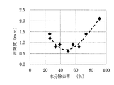
- FIG. 2 is a graph showing the relationship between the moisture content and cylindricity of the primary dried honeycomb molded body in the method for drying a honeycomb molded body of the present invention.
- the cylindricity is the maximum dimension when the dried honeycomb body is measured at a plurality of positions (outer diameter (see symbol Y in FIG. 1)) in the cell extending direction (X direction in FIG. 1). And the difference between the minimum dimensions.
- the moisture content of the primary dried honeycomb formed body is within the above range is determined as follows.
- the moisture content of the green honeycomb molded body before drying is calculated by measuring the wet mixed powder with an infrared heating moisture meter.
- the weight of the unfired honeycomb formed body before drying and the weight of the honeycomb formed body after dielectric drying were measured. Calculate from quantity. In this way, it is possible to obtain a primary dried honeycomb formed body from which 30 to 70% of the total moisture contained in the unfired honeycomb formed body has been removed. It should be noted that dielectric drying is performed in advance under a plurality of drying conditions, and conditions under which the moisture content of the primary dried honeycomb formed body is within the above range can be confirmed.
- the primary dried honeycomb formed body needs to be obtained by removing moisture of 30 to 70% of the total moisture contained in the unfired honeycomb formed body before drying.
- the primary dried honeycomb formed body is preferably obtained by removing 40 to 60% of the total moisture contained in the unfired honeycomb formed body before drying. Further, it is more preferable that the primary dried honeycomb formed body is obtained by removing 40 to 50% of the total moisture contained in the unfired honeycomb formed body before drying.
- the unfired honeycomb formed body it is necessary to perform dielectric drying on the unfired honeycomb formed body while maintaining the temperature at the center of the unfired honeycomb formed body at 100 ° C. or lower.
- the temperature of the central portion of the unfired honeycomb formed body is maintained at 100 ° C. or less, it is possible to prevent the occurrence of a portion that is locally dried in the unfired honeycomb formed body. This is because when a portion that is locally dried occurs, thermal stress is generated in the portion, and cracks are likely to occur.
- the reason why the temperature of the central portion of the unfired honeycomb formed body is measured is that this central portion has the highest temperature in dielectric drying. That is, if the central portion is 100 ° C. or lower, the other portions are also 100 ° C. or lower.
- the temperature at the center of the unfired honeycomb formed body is a value measured with an optical fiber thermometer.
- the conditions for performing dielectric drying on the unfired honeycomb formed body while maintaining the temperature of the central portion of the unfired honeycomb formed body at 100 ° C. or less can be appropriately determined. Specifically, in a preliminary test, a small temperature measuring device was embedded in the product (an unfired honeycomb molded body before drying), and the output and drying time of the dryer capable of keeping the temperature at the center at 100 ° C or lower were determined. To do. The conditions for performing dielectric drying can be set in this way.
- the moisture content of the “unfired honeycomb formed body” is a value obtained by measuring the wet mixed powder with an infrared heating moisture meter.
- a frequency of 10 to 50 MHz is generally used.
- the unfired honeycomb formed body can be manufactured by a conventionally known method. Specifically, first, a cell wall that forms a raw material composition containing a ceramic raw material and water and defines a plurality of cells extending from a first end surface that is one end surface to a second end surface that is the other end surface. To form an unfired honeycomb formed body.
- the ceramic raw material contained in the raw material composition is preferably at least one selected from the group consisting of cordierite forming raw material, cordierite, silicon carbide, silicon-silicon carbide based composite material, mullite, and aluminum titanate.
- the cordierite forming raw material is a ceramic raw material blended so as to have a chemical composition in the range of 42 to 56% by mass of silica, 30 to 45% by mass of alumina, and 12 to 16% by mass of magnesia. And the cordierite-forming raw material is fired to become cordierite.
- the raw material composition can be prepared by mixing a dispersion medium, an organic binder, an inorganic binder, a pore former, a surfactant and the like in addition to the ceramic raw material and water.
- the composition ratio of each raw material is not particularly limited, and is preferably a composition ratio in accordance with the structure and material of the honeycomb structure to be manufactured.
- the raw material composition When forming the raw material composition, first, the raw material composition is kneaded to form a clay, and the obtained clay is formed into a honeycomb shape.
- a method for kneading the raw material composition to form a clay include a method using a kneader, a vacuum kneader, or the like.
- a method for forming a kneaded clay to form a honeycomb formed body for example, a known forming method such as extrusion molding or injection molding can be used.
- a preferable example includes a method of forming a honeycomb formed body by extrusion using a die having a desired cell shape, partition wall (cell wall) thickness, and cell density.
- a cemented carbide that does not easily wear can be used.
- the cell shape of the unfired honeycomb molded body is not particularly limited. Examples of the cell shape include a triangle, a quadrangle, a hexagon, an octagon, a circle, or a combination thereof.
- Examples of the shape of the honeycomb formed body include a columnar shape, an elliptical columnar shape, and a polygonal columnar shape whose end faces are “square, rectangular, triangular, pentagonal, hexagonal, octagonal, etc.”.
- the unfired honeycomb formed body can have a cylindrical shape.
- the diameter of the end face of the unfired honeycomb formed body is preferably 50 to 200 mm.
- the unfired honeycomb formed body preferably has a length in the cell extending direction of 150 to 350 mm.
- the green honeycomb formed body preferably has a cell wall thickness of 50 to 350 ⁇ m.
- the microwave output in the microwave drying in this step is set so that the temperature of the honeycomb dried body does not exceed 150 ° C. in consideration of the possibility of ignition of the binder contained in the honeycomb molded body.
- the drying time is set by measuring the weight of the honeycomb formed body so that the remaining moisture falls to a level that does not affect the firing process.
- One embodiment of the method for manufacturing a honeycomb structure of the present invention includes a honeycomb formed body manufacturing step, a drying step, and a firing step.
- a honeycomb structure can be manufactured by these steps.
- a honeycomb structure having a good quality that is, a difference (cylindricity) between the maximum dimension and the minimum dimension of the entire side surface of the honeycomb structure is small
- a clay can be manufactured as described above. That is, a raw material obtained by adding various additives such as water and a binder to a ceramic raw material (ceramic material) is kneaded to obtain a clay. Thereafter, the kneaded material is extruded to produce a honeycomb-shaped formed body (honeycomb formed body).
- the honeycomb formed body manufactured in the honeycomb formed body manufacturing step is dried by the above-described method for drying a honeycomb formed body of the present invention to obtain a dried honeycomb body.
- the honeycomb dried body obtained in the drying step is fired to obtain a honeycomb structure.
- Conventionally known conditions can be appropriately adopted as the firing conditions.
- Example 1 First, a cordierite forming raw material in which alumina, kaolin and talc are mixed as a ceramic raw material is mixed with a binder containing an organic binder, a pore former, and water (73% by mass) as a dispersion medium, and kneaded to prepare a clay. Obtained.
- the obtained clay was extruded to obtain an unfired honeycomb formed body having cells having a square cross section perpendicular to the cell extending direction.
- This unfired honeycomb formed body has a diameter (maximum length in the Y direction in FIG. 1) 126 mm and a length (length in the cell extending direction (length in the X direction in FIG. 1)) 220 mm.
- the outer shape was cylindrical.
- the obtained unfired honeycomb formed body had a moisture content of 42%, a cell density of 40 cells / cm 2 , a cell wall thickness of 210 ⁇ m, and a mass of 1250 g.
- Two such unfired honeycomb formed bodies were prepared, and these were dried as follows.
- the obtained unfired honeycomb formed body was subjected to dielectric drying in batches using a dielectric drying apparatus at a frequency of 13 MHz, an output of 5 kW, and a heating time of 500 seconds (dielectric drying step).
- a primary dried honeycomb formed body from which 64% of the total moisture contained in the unfired honeycomb formed body was removed before drying was obtained.
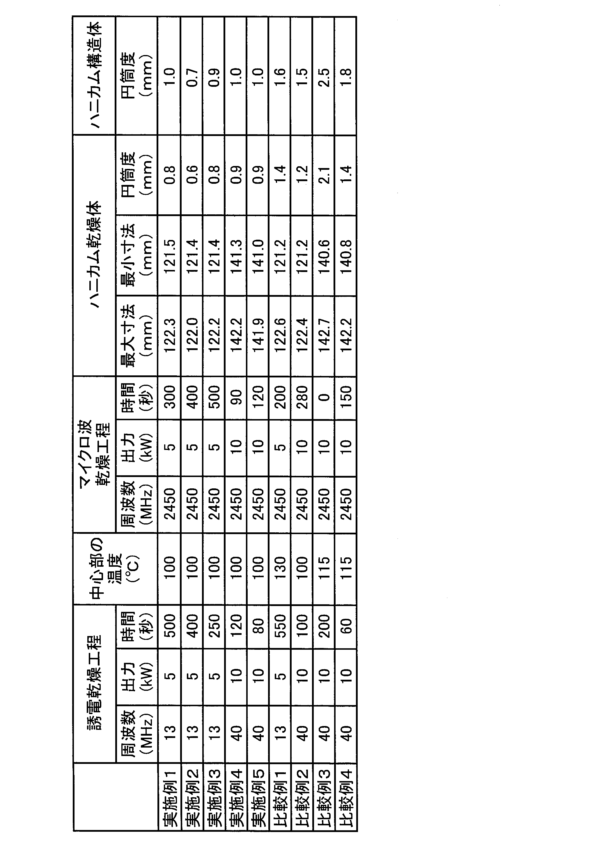
- Table 1 the ratio of moisture removed from the total moisture contained in the unfired honeycomb formed body before drying is shown as “moisture removal rate (%)”.
- the primary dried honeycomb formed body was subjected to microwave drying in batches at a frequency of 2450 MHz, an output of 5 kW, and a heating time of 300 seconds to remove residual moisture (microwave Drying step).
- the moisture content of the primary dried honeycomb formed body (honeycomb dried body) after microwave drying was measured, and it was confirmed that the honeycomb dried body was dried.
- the moisture content of the dried honeycomb body was 2%.
- FIG. 3 shows the measurement results for the two dried honeycomb bodies. Show).
- the cylindricity is shown as an average value in a plurality of honeycomb dried bodies.
- “height” indicates the position in the cell extending direction (position in the X direction in FIG. 1).
- “outer diameter” indicates the diameter of the honeycomb dried body (the maximum length in the Y direction in FIG. 1). The same applies to FIGS.
- the cylindricity is preferably 1 mm or less.
- the obtained dried honeycomb body was fired, and the difference (cylindricity) between the maximum dimension and the minimum dimension of the entire side face of the honeycomb fired body was calculated.
- the result was 1.0 mm.
- the baking conditions were conventionally known conditions (specifically, the maximum temperature was 1400 ° C. for 5 hours).
- Examples 2 to 5 Comparative Examples 1 to 4
- An unfired honeycomb formed body was dried in the same manner as in Example 1 except that the conditions were changed as shown in Tables 1 and 2.
- the results of this drying method are shown in Tables 1 and 2.
- Example 4 the moisture content of the unfired honeycomb formed body was 23%.
- Comparative Example 2 the same honeycomb formed body as the unfired honeycomb formed body used in Example 1 was used, and 26% of the total moisture contained in the unfired honeycomb formed body before drying was removed. A dried honeycomb formed body was obtained.
- Comparative Example 2 there was a crack in the honeycomb formed body when the dielectric drying process was shifted to the microwave drying process.
- “clear” refers to a state in which a part of the partition walls of the honeycomb formed body is torn.
- Example 2 In Examples 2 to 5 and Comparative Examples 1 to 4, as in the case of Example 1, the obtained honeycomb dried body was measured for cylindricity after firing. The results are shown in Table 2.
- the obtained honeycomb structure has a good cylindricity, and it can be seen that according to the method for manufacturing a honeycomb structure of the present invention, a good quality honeycomb structure can be obtained with high productivity.
- the method for drying a honeycomb formed body of the present invention can be suitably used as a manufacturing process for a filter that purifies exhaust gas from an automobile or the like.
- the method for manufacturing a honeycomb structure of the present invention can be employed as a method for manufacturing a filter that purifies exhaust gas from an automobile or the like.
- 1 cell wall
- 2 cell
- 11 first end face
- 12 second end face
- 100 honeycomb formed body
- X cell extending direction (height)
- Y diameter (outer diameter).
Landscapes
- Engineering & Computer Science (AREA)
- Ceramic Engineering (AREA)
- Structural Engineering (AREA)
- Chemical & Material Sciences (AREA)
- Mechanical Engineering (AREA)
- Devices For Post-Treatments, Processing, Supply, Discharge, And Other Processes (AREA)
- Press-Shaping Or Shaping Using Conveyers (AREA)
Abstract
乾燥中におけるハニカム成形体内の温度分布のバラツキが小さく均一に乾燥でき、良好な品質のハニカム乾燥体を生産性良く得るハニカム成形体の乾燥方法を提供するものであり、セラミック原料、及び水を含有する原料組成物から構成され、一方の端面から他方の端面まで延びる複数のセルを区画形成するセル壁を備える未焼成のハニカム成形体の乾燥方法であって、未焼成のハニカム成形体の中心部の温度を100℃以下に維持しながら未焼成のハニカム成形体について誘電乾燥を行い、未焼成のハニカム成形体が乾燥前に含む全水分の30~70%の水分を除去した第1次乾燥ハニカム成形体を得る誘電乾燥工程と、誘電乾燥工程によって得られた第1次乾燥ハニカム成形体についてマイクロ波乾燥を行って残余の水分を除去したハニカム乾燥体を得るマイクロ波乾燥工程と、を有するハニカム成形体の乾燥方法。
Description
本発明は、ハニカム成形体の乾燥方法及びハニカム構造体の製造方法に関する。更に詳しくは、本発明は、乾燥中におけるハニカム成形体内の温度分布のバラツキが小さく均一に乾燥でき、良好な品質のハニカム乾燥体を生産性良く得ることができるハニカム成形体の乾燥方法及びハニカム構造体の製造方法に関する。
従来、セラミックス製のハニカム構造体は、触媒担体や各種フィルタ等に広く用いられている。また、このセラミックス製のハニカム構造体は、ディーゼルエンジンから排出される粒子状物質(パティキュレートマター(PM))を捕捉するためのディーゼルパティキュレートフィルタ(DPF)としても使用されている。
このようなハニカム構造体は、一般に、坏土を押出成形して、ハニカム形状の成形体(ハニカム成形体)を作製し、このハニカム成形体を乾燥した後に、焼成して、得ることができる。なお、坏土は、セラミックス材料に、水、バインダ等の各種添加剤を加えて得られた原料を混練して得られる。
そして、ハニカム成形体を乾燥する手段としては、以下の方法が知られている。具体的には、単に室温条件下に放置する自然乾燥法、ガスバーナで発生させた熱風を導入して乾燥を行う熱風乾燥法、誘電乾燥法、マイクロ波を利用したマイクロ波乾燥法等が知られている(例えば、特許文献1、2を参照)。なお、誘電乾燥法は、ハニカム成形体の上方と下方とに設けた電極間に電流を流すことによって発生させた高周波エネルギーを利用して乾燥を行う方法である。
しかしながら、特許文献1、2に記載のハニカム構造体の乾燥方法のように誘電乾燥またはマイクロ波乾燥のみを用いて乾燥させる方法であると、以下の問題がある。即ち、例えばコージェライト製のハニカム成形体の乾燥工程において、誘電乾燥及びマイクロ波乾燥では各々加熱分布を持って乾燥が進行していく。そのため、ハニカム成形体の一方の端部、他方の端部、及び、これらの中間部における寸法に大きな差異が生じた状態で乾燥が進むことになる。その結果、得られるハニカム乾燥体は、規定の寸法に収まらないことがある。そのため、ハニカム乾燥体において外周部を研削するなどの方法により寸法を調整する手間が増え、最終的な製品であるハニカム構造体の生産性の低下や生産が困難となるという問題が生じてしまうことがある。
本発明は、上述した問題に鑑みてなされたものである。本発明は、乾燥中におけるハニカム成形体内の温度分布のバラツキが小さく均一に乾燥でき、良好な品質のハニカム乾燥体を生産性良く得ることができるハニカム成形体の乾燥方法及びハニカム構造体の製造方法を提供するものである。
[1] セラミック原料、及び水を含有する原料組成物から構成され、一方の端面である第1端面から他方の端面である第2端面まで延びる複数のセルを区画形成するセル壁を備える未焼成のハニカム成形体の乾燥方法であって、前記未焼成のハニカム成形体の中心部の温度を100℃以下に維持しながら前記未焼成のハニカム成形体について誘電乾燥を行い、前記未焼成のハニカム成形体が乾燥前に含む全水分の30~70%の水分を除去した第1次乾燥ハニカム成形体を得る誘電乾燥工程と、前記誘電乾燥工程によって得られた前記第1次乾燥ハニカム成形体についてマイクロ波乾燥を行って残余の水分を除去したハニカム乾燥体を得るマイクロ波乾燥工程と、を有するハニカム成形体の乾燥方法。
[2] 前記誘電乾燥工程に供する前記未焼成のハニカム成形体の乾燥前の含水率が、20~60%である前記[1]に記載のハニカム成形体の乾燥方法。
[3] 前記誘電乾燥工程に供する前記未焼成のハニカム成形体は円柱状であり、前記未焼成のハニカム成形体の端面における直径が50~200mmであり、前記未焼成のハニカム成形体の前記セルの延びる方向の長さが150~350mmであり、前記未焼成のハニカム成形体の前記セル壁の厚さが50~350μmである前記[1]または[2]に記載のハニカム成形体の乾燥方法。
[4] セラミックス材料に添加剤を加えて得られた原料を混練し、坏土とした後、前記坏土をハニカム形状に押出成形して、ハニカム成形体を作製するハニカム成形体作製工程と、作製した前記ハニカム成形体を、前記[1]~[3]のいずれかに記載のハニカム成形体の乾燥方法によって乾燥してハニカム乾燥体を得る乾燥工程と、得られた前記ハニカム乾燥体を焼成し、ハニカム構造体を得る焼成工程と、を有するハニカム構造体の製造方法。
本発明のハニカム成形体の乾燥方法によれば、乾燥中におけるハニカム成形体内の温度分布のバラツキが小さく均一に乾燥でき、良好な品質のハニカム乾燥体を生産性良く得ることができる。
本発明のハニカム構造体の製造方法によれば、良好な品質のハニカム構造体を生産性良く得ることができる。
以下、本発明の実施の形態について、図面を参照しながら具体的に説明する。本発明は以下の実施の形態に限定されるものではない。本発明の趣旨を逸脱しない範囲で、当業者の通常の知識に基づいて、以下の実施の形態に対し適宜変更、改良等が加えられたものも本発明の範囲に入ることが理解されるべきである。
(1)ハニカム成形体の乾燥方法:
本発明のハニカム成形体の乾燥方法は、セラミック原料、及び水を含有する原料組成物から構成され、一方の端面である第1端面11から他方の端面である第2端面12まで延びる複数のセル2を区画形成するセル壁1を備える未焼成のハニカム成形体100の乾燥方法である。つまり、本発明のハニカム成形体の乾燥方法は、未焼成のハニカム成形体に対して、乾燥を行う方法である。具体的には、本発明のハニカム成形体の乾燥方法は、乾燥していない未焼成のハニカム成形体(即ち、水分を含み粘土状のハニカム成形体)から乾燥した未焼成のハニカム成形体(ハニカム乾燥体)を製造する方法である。なお、未焼成のハニカム成形体とは、セラミック原料の粒子が、原料組成物をハニカム形状に成形したときの粒子形状を維持した状態で存在し、セラミック原料が焼結していない状態のものをいう。図1は、本発明のハニカム成形体の乾燥方法における乾燥対象の一実施形態を模式的に示す斜視図である。
本発明のハニカム成形体の乾燥方法は、セラミック原料、及び水を含有する原料組成物から構成され、一方の端面である第1端面11から他方の端面である第2端面12まで延びる複数のセル2を区画形成するセル壁1を備える未焼成のハニカム成形体100の乾燥方法である。つまり、本発明のハニカム成形体の乾燥方法は、未焼成のハニカム成形体に対して、乾燥を行う方法である。具体的には、本発明のハニカム成形体の乾燥方法は、乾燥していない未焼成のハニカム成形体(即ち、水分を含み粘土状のハニカム成形体)から乾燥した未焼成のハニカム成形体(ハニカム乾燥体)を製造する方法である。なお、未焼成のハニカム成形体とは、セラミック原料の粒子が、原料組成物をハニカム形状に成形したときの粒子形状を維持した状態で存在し、セラミック原料が焼結していない状態のものをいう。図1は、本発明のハニカム成形体の乾燥方法における乾燥対象の一実施形態を模式的に示す斜視図である。
本発明のハニカム成形体の乾燥方法は、誘電乾燥工程とマイクロ波乾燥工程とを有している。誘電乾燥工程は、未焼成のハニカム成形体の中心部の温度を100℃以下に維持しながら未焼成のハニカム成形体について誘電乾燥を行い、未焼成のハニカム成形体の全水分の30~70%の水分を含む第1次乾燥ハニカム成形体を得る工程である。また、マイクロ波乾燥工程は、誘電乾燥工程によって得られた第1次乾燥ハニカム成形体についてマイクロ波乾燥を行ってハニカム乾燥体を得る工程である。
このようなハニカム成形体の乾燥方法によれば、誘電乾燥とマイクロ波乾燥の配分を最適に決定することで、乾燥中におけるハニカム成形体内の温度分布のバラツキが小さくなる。そのため、得られるハニカム乾燥体の寸法(セルの延びる方向の寸法)のバラツキが改善される。その結果、製品の品質が確保し易くなり、生産性が向上する。
(1-1)誘電乾燥工程:
本工程においては、未焼成のハニカム成形体が乾燥前に含む全水分の30~70%の水分を除去した第1次乾燥ハニカム成形体を得る。即ち、未焼成のハニカム成形体が乾燥前に含む全水分の30~70%の水分が除去された段階で本工程は終了となり、マイクロ波乾燥工程に移行することになる。誘電乾燥は、製品の中央部から加熱し、マイクロ波乾燥は外表面から加熱される。どちらか一方の乾燥方法のみで乾燥させると、加熱が中央部又は外表面に集中する。そこで、両乾燥方法を組合せることにより、中央部と外表面との温度差を小さくすることができる。但し、先にマイクロ波乾燥を行うと、外表面が先に加熱されることによって外皮(外表面)からの乾燥収縮が生じるので、製品(ハニカム成形体)内部に圧力が加わりセルの変形が発生する。
本工程においては、未焼成のハニカム成形体が乾燥前に含む全水分の30~70%の水分を除去した第1次乾燥ハニカム成形体を得る。即ち、未焼成のハニカム成形体が乾燥前に含む全水分の30~70%の水分が除去された段階で本工程は終了となり、マイクロ波乾燥工程に移行することになる。誘電乾燥は、製品の中央部から加熱し、マイクロ波乾燥は外表面から加熱される。どちらか一方の乾燥方法のみで乾燥させると、加熱が中央部又は外表面に集中する。そこで、両乾燥方法を組合せることにより、中央部と外表面との温度差を小さくすることができる。但し、先にマイクロ波乾燥を行うと、外表面が先に加熱されることによって外皮(外表面)からの乾燥収縮が生じるので、製品(ハニカム成形体)内部に圧力が加わりセルの変形が発生する。
図2は、本発明のハニカム成形体の乾燥方法における第1次乾燥ハニカム成形体の含水率と円筒度との関係を示すグラフである。なお、円筒度は、ハニカム乾燥体を、そのセルの延びる方向(図1中のX方向)に複数の位置で寸法(外径(図1中の符号Y参照))を測定したときの最大寸法と最小寸法との差を意味する。
第1次乾燥ハニカム成形体の含水率が上記範囲内であるか否かについては、以下のように判断する。乾燥前の未焼成のハニカム成形体の含水率は、湿式混合粉を赤外線加熱式水分計で測定することにより算出する。第一次乾燥ハニカム成形体の含水率については、乾燥前の未焼成ハニカム成形体の重量及び誘電乾燥後のハニカム成形体(第1次乾燥ハニカム成形体)の重量を測定し、飛散した水分の量から計算する。このようにして未焼成のハニカム成形体が乾燥前に含む全水分の30~70%の水分が除去された第1次乾燥ハニカム成形体を得ることができる。なお、予め複数の乾燥条件で誘電乾燥を行い、第1次乾燥ハニカム成形体の含水率が上記範囲内となる条件を確認しておくことができる。
第1次乾燥ハニカム成形体は、上記のように、未焼成のハニカム成形体が乾燥前に含む全水分の30~70%の水分を除去したものであることが必要である。そして、第1次乾燥ハニカム成形体は、未焼成のハニカム成形体が乾燥前に含む全水分の40~60%の水分を除去したものであることが好ましい。更に、第1次乾燥ハニカム成形体は、未焼成のハニカム成形体が乾燥前に含む全水分の40~50%の水分を除去したものであることが更に好ましい。
本工程においては、未焼成のハニカム成形体の中心部の温度を100℃以下に維持しながら未焼成のハニカム成形体について誘電乾燥を行うことが必要である。このように未焼成のハニカム成形体の中心部の温度を100℃以下に維持することにより、未焼成のハニカム成形体において局所的に乾燥してしまう部分の発生を防止することができる。局所的に乾燥してしまう部分が発生すると、その部分において熱応力が生じてクラックが発生し易くなるためである。なお、未焼成のハニカム成形体の中心部の温度を測定するのは、誘電乾燥においてこの中心部が最も温度が高いためである。即ち、この中心部が100℃以下であれば、その他の部分も100℃以下となるためである。未焼成のハニカム成形体の中心部の温度は、光ファイバー温度計により測定した値である。
本工程において、未焼成のハニカム成形体の中心部の温度を100℃以下に維持しながら未焼成のハニカム成形体について誘電乾燥を行う条件は、適宜決定することができる。具体的には、予備試験で小型測温装置を製品(乾燥前の未焼成のハニカム成形体)に埋め込み、中心部の温度を100℃以下に保つことができる乾燥機の出力及び乾燥時間を決定する。誘電乾燥を行う条件は、このようにして設定することができる。
含水率は、製品の要求特性によって異なるので、含水率に応じて乾燥機の出力及び乾燥時間を設定する。対応可能な含水率は20~60%の範囲にある。なお、「未焼成のハニカム成形体」の含水率は、湿式混合粉を赤外線加熱式水分計にて測定した値である。
本工程である未焼成のハニカム成形体の誘電乾燥では、一般的に10~50MHzの周波数が用いられる。
(1-1-1)未焼成のハニカム成形体の成形:
未焼成のハニカム成形体は、従来公知の方法で作製できる。具体的には、まず、セラミック原料及び水を含有する原料組成物を成形して、一方の端面である第1端面から他方の端面である第2端面まで延びる複数のセルを区画形成するセル壁を備える未焼成のハニカム成形体を形成する。
未焼成のハニカム成形体は、従来公知の方法で作製できる。具体的には、まず、セラミック原料及び水を含有する原料組成物を成形して、一方の端面である第1端面から他方の端面である第2端面まで延びる複数のセルを区画形成するセル壁を備える未焼成のハニカム成形体を形成する。
原料組成物に含有されるセラミック原料としては、コージェライト化原料、コージェライト、炭化珪素、珪素-炭化珪素系複合材料、ムライト、及びチタン酸アルミニウムからなる群より選択される少なくとも1種が好ましい。なお、コージェライト化原料とは、シリカが42~56質量%、アルミナが30~45質量%、マグネシアが12~16質量%の範囲に入る化学組成となるように配合されたセラミック原料である。そして、コージェライト化原料は、焼成されてコージェライトになるものである。
原料組成物は、上記セラミック原料と水以外に、分散媒、有機バインダ、無機バインダ、造孔材、界面活性剤等を混合して調製することができる。各原料の組成比は、特に限定されず、作製しようとするハニカム構造体の構造、材質等に合わせた組成比とすることが好ましい。
原料組成物を成形する際には、まず、原料組成物を混練して坏土とし、得られた坏土をハニカム形状に成形する。原料組成物を混練して坏土を形成する方法としては、例えば、ニーダー、真空土練機等を用いる方法を挙げることができる。坏土を成形してハニカム成形体を形成する方法としては、例えば、押出成形、射出成形等の公知の成形方法を用いることができる。具体的には、所望のセル形状、隔壁(セル壁)の厚さ、セル密度を有する口金を用いて押出成形してハニカム成形体を形成する方法等を好適例として挙げることができる。口金の材質としては、摩耗し難い超硬合金を用いることができる。
未焼成のハニカム成形体のセル形状(セルが延びる方向に直交する断面におけるセル形状)としては、特に制限はない。セル形状としては、三角形、四角形、六角形、八角形、円形、あるいはこれらの組合せを挙げることができる。
ハニカム成形体の形状としては、円柱状、楕円柱状、端面が「正方形、長方形、三角形、五角形、六角形、八角形等」の多角柱状等を挙げることができる。
未焼成のハニカム成形体は、上記の通り、円柱状とすることができ、この場合、未焼成のハニカム成形体の端面における直径は50~200mmとすることが好ましい。また、未焼成のハニカム成形体は、セルの延びる方向の長さが150~350mmであることが好ましい。未焼成のハニカム成形体は、セル壁の厚さが50~350μmであることが好ましい。上記のような条件を満たす未焼成のハニカム成形体を乾燥する場合、乾燥中におけるハニカム成形体内の温度分布のバラツキが更に小さく均一に乾燥できる。そのため、更に良好な品質のハニカム乾燥体を生産性良く得ることができる。
(1-2)マイクロ波乾燥工程:
本工程であるハニカム成形体のマイクロ波乾燥では、一般的に1,000~10,000MHzの周波数が用いられる。
本工程であるハニカム成形体のマイクロ波乾燥では、一般的に1,000~10,000MHzの周波数が用いられる。
本工程におけるマイクロ波乾燥におけるマイクロ波の出力は、ハニカム成形体に含まれるバインダ等の発火の可能性を考慮して、ハニカム乾燥体の温度が150℃を超えないように設定する。乾燥時間は、残存する水分が焼成工程に影響しないレベルに下がるようにハニカム成形体の重量を測定して設定する。
(2)ハニカム構造体の製造方法:
本発明のハニカム構造体の製造方法の一実施形態としては、ハニカム成形体作製工程と、乾燥工程と、焼成工程と、を有している。これらの工程により、ハニカム構造体を製造することができる。本発明のハニカム構造体の製造方法によれば、良好な品質の(即ち、ハニカム構造体の側面全体での最大寸法と最小寸法との差(円筒度)が小さい)ハニカム構造体を生産性良く得ることができる。
本発明のハニカム構造体の製造方法の一実施形態としては、ハニカム成形体作製工程と、乾燥工程と、焼成工程と、を有している。これらの工程により、ハニカム構造体を製造することができる。本発明のハニカム構造体の製造方法によれば、良好な品質の(即ち、ハニカム構造体の側面全体での最大寸法と最小寸法との差(円筒度)が小さい)ハニカム構造体を生産性良く得ることができる。
ハニカム成形体作製工程では、まず、上述したように坏土を作製できる。即ち、セラミック原料(セラミックス材料)に、水、バインダ等の各種添加剤を加えて得られた原料を混練し、坏土とする。その後、この坏土を押出成形して、ハニカム形状の成形体(ハニカム成形体)を作製する。
乾燥工程では、ハニカム成形体作製工程で作製したハニカム成形体を上述した本発明のハニカム成形体の乾燥方法によって乾燥して、ハニカム乾燥体を得る。
焼成工程では、乾燥工程で得られたハニカム乾燥体を焼成してハニカム構造体を得る。焼成条件は、従来公知の条件を適宜採用することができる。
以下、本発明を、実施例により更に具体的に説明する。本発明は、これらの実施例によって何ら限定されるものではない。
(実施例1)
まず、セラミック原料としてアルミナ、カオリン及びタルクを混合したコージェライト化原料を用い、有機バインダを含む結合材、造孔材、分散媒として水(73質量%)を混合し、混練して坏土を得た。
まず、セラミック原料としてアルミナ、カオリン及びタルクを混合したコージェライト化原料を用い、有機バインダを含む結合材、造孔材、分散媒として水(73質量%)を混合し、混練して坏土を得た。
得られた坏土を押出成形し、セルの延びる方向に直交する断面形状が正方形であるセルを有する未焼成のハニカム成形体を得た。この未焼成のハニカム成形体は、直径(図1中のY方向の最大長さ)126mm、長さ(セルの延びる方向の長さ(図1中のX方向の長さ))220mmであり、外形が円柱状であった。
得られた未焼成のハニカム成形体は、含水率が42%であり、セル密度が40個/cm2であり、セル壁の厚さが210μmであり、質量が1250gであった。このような未焼成のハニカム成形体を2個用意し、これらについて以下のようにして乾燥操作を行った。
得られた未焼成のハニカム成形体に対して、誘電乾燥装置を使用して、周波数13MHz、出力5kW、加熱時間500秒間として、バッチで誘電乾燥を行った(誘電乾燥工程)。このようにして、未焼成のハニカム成形体が乾燥前に含む全水分の64%の水分を除去した第1次乾燥ハニカム成形体を得た。なお、上記乾燥条件によれば、未焼成のハニカム成形体の中心部の温度は100℃となることを光ファイバー温度計による測定で予め確認した。なお、表1中、未焼成のハニカム成形体が乾燥前に含む全水分から除去された水分の割合を「水分除去率(%)」と示す。
次に、マイクロ波乾燥装置を使用して、第1次乾燥ハニカム成形体について、周波数2450MHz、出力5kW、加熱時間300秒間として、バッチでマイクロ波乾燥を行い、残余の水分を除去した(マイクロ波乾燥工程)。
次に、マイクロ波乾燥後の第1次乾燥ハニカム成形体(ハニカム乾燥体)について、含水率を測定して、ハニカム乾燥体が乾燥されていることを確認した。その結果、ハニカム乾燥体の含水率は、2%であった。
また、ハニカム乾燥体について、一方の端面である第1端面から他方の端面である第2端面までの間の複数個所における寸法を測定した(図3は、2つのハニカム乾燥体についての測定結果を示す)。その結果、ハニカム乾燥体の側面全体での最大寸法と最小寸法との差(円筒度)は、0.8mmであり、良好な品質のハニカム乾燥体を生産性良く得ることができた。なお、円筒度は、複数のハニカム乾燥体における平均値で示す。図3中、「高さ」は、セルの延びる方向の位置(図1中のX方向の位置)を示す。また、図3中、「外径」は、ハニカム乾燥体の直径(図1中のY方向の最大長さ)を示す。図4~図6も同様である。円筒度は、1mm以下であることがよい。
また、得られたハニカム乾燥体について焼成を行い、ハニカム焼成体の側面全体での最大寸法と最小寸法との差(円筒度)を算出した。その結果は、1.0mmであった。本実施例では、一方の端部、他方の端部、及び、これらの中間部における寸法の差異が小さい良好な品質のハニカム構造体を生産性良く得ることができた。なお、焼成条件は、従来公知の条件で行った(具体的には、最高温度1400℃で5時間)。

(実施例2~5、比較例1~4)
表1、表2に示すように条件を変更した以外は、実施例1と同様にして未焼成のハニカム成形体を乾燥した。この乾燥方法における結果を表1、表2に示す。
表1、表2に示すように条件を変更した以外は、実施例1と同様にして未焼成のハニカム成形体を乾燥した。この乾燥方法における結果を表1、表2に示す。
実施例4、5では、未焼成のハニカム成形体の含水率は23%であった。また、比較例2では、実施例1で使用した未焼成のハニカム成形体と同じハニカム成形体を使用し、未焼成のハニカム成形体が乾燥前に含む全水分の26%の水分が除去された乾燥ハニカム成形体を得た。この比較例2では、誘電乾燥工程からマイクロ波乾燥工程に移行した際にハニカム成形体にキレの発生があった。なお、「キレ」とは、ハニカム成形体の隔壁の一部が裂けた状態のことをいう。
なお、実施例2~5、比較例1~4においても、実施例1の場合と同様に、得られたハニカム乾燥体について焼成を行った後の円筒度を測定した。その結果を表2に示す。
表1、表2から、実施例1~5のハニカム成形体の乾燥方法によれば、比較例1~4のハニカム成形体の乾燥方法に比べて、乾燥分布が小さくて均一に乾燥でき、良好な品質のハニカム乾燥体を生産性良く得ることができることが分かる。
また、得られるハニカム構造体においても円筒度が良好であり、本発明のハニカム構造体の製造方法によれば、良好な品質のハニカム構造体を生産性良く得ることができることが分かる。
本発明のハニカム成形体の乾燥方法は、自動車等の排ガスを浄化するフィルタの製造工程として好適に利用することができる。本発明のハニカム構造体の製造方法は、自動車等の排ガスを浄化するフィルタの製造方法として採用することができる。
1:セル壁、2:セル、11:第1端面、12:第2端面、100:ハニカム成形体、X:セルの延びる方向(高さ)、Y:直径(外径)。
Claims (4)
- セラミック原料、及び水を含有する原料組成物から構成され、一方の端面である第1端面から他方の端面である第2端面まで延びる複数のセルを区画形成するセル壁を備える未焼成のハニカム成形体の乾燥方法であって、
前記未焼成のハニカム成形体の中心部の温度を100℃以下に維持しながら前記未焼成のハニカム成形体について誘電乾燥を行い、前記未焼成のハニカム成形体が乾燥前に含む全水分の30~70%の水分を除去した第1次乾燥ハニカム成形体を得る誘電乾燥工程と、
前記誘電乾燥工程によって得られた前記第1次乾燥ハニカム成形体についてマイクロ波乾燥を行って残余の水分を除去したハニカム乾燥体を得るマイクロ波乾燥工程と、を有するハニカム成形体の乾燥方法。 - 前記誘電乾燥工程に供する前記未焼成のハニカム成形体の乾燥前の含水率が、20~60%である請求項1に記載のハニカム成形体の乾燥方法。
- 前記誘電乾燥工程に供する前記未焼成のハニカム成形体は円柱状であり、前記未焼成のハニカム成形体の端面における直径が50~200mmであり、前記未焼成のハニカム成形体の前記セルの延びる方向の長さが150~350mmであり、前記未焼成のハニカム成形体の前記セル壁の厚さが50~350μmである請求項1または2に記載のハニカム成形体の乾燥方法。
- セラミックス材料に添加剤を加えて得られた原料を混練し、坏土とした後、前記坏土をハニカム形状に押出成形して、ハニカム成形体を作製するハニカム成形体作製工程と、
作製した前記ハニカム成形体を、請求項1~3のいずれか一項に記載のハニカム成形体の乾燥方法によって乾燥してハニカム乾燥体を得る乾燥工程と、
得られた前記ハニカム乾燥体を焼成し、ハニカム構造体を得る焼成工程と、を有するハニカム構造体の製造方法。
Priority Applications (4)
| Application Number | Priority Date | Filing Date | Title |
|---|---|---|---|
| DE112017001714.9T DE112017001714T5 (de) | 2016-03-30 | 2017-02-03 | Verfahren zum Trocknen eines Wabenformkörpers und Verfahren zur Herstellung einer Wabenstruktur |
| CN201780013425.8A CN109070384A (zh) | 2016-03-30 | 2017-02-03 | 蜂窝成型体的干燥方法及蜂窝结构体的制造方法 |
| JP2018508486A JP6811769B2 (ja) | 2016-03-30 | 2017-02-03 | ハニカム成形体の乾燥方法及びハニカム構造体の製造方法 |
| US16/106,183 US11607824B2 (en) | 2016-03-30 | 2018-08-21 | Method for drying honeycomb formed body and method for manufacturing honeycomb structure |
Applications Claiming Priority (2)
| Application Number | Priority Date | Filing Date | Title |
|---|---|---|---|
| JP2016-067010 | 2016-03-30 | ||
| JP2016067010 | 2016-03-30 |
Related Child Applications (1)
| Application Number | Title | Priority Date | Filing Date |
|---|---|---|---|
| US16/106,183 Continuation US11607824B2 (en) | 2016-03-30 | 2018-08-21 | Method for drying honeycomb formed body and method for manufacturing honeycomb structure |
Publications (1)
| Publication Number | Publication Date |
|---|---|
| WO2017169104A1 true WO2017169104A1 (ja) | 2017-10-05 |
Family
ID=59963907
Family Applications (1)
| Application Number | Title | Priority Date | Filing Date |
|---|---|---|---|
| PCT/JP2017/003953 Ceased WO2017169104A1 (ja) | 2016-03-30 | 2017-02-03 | ハニカム成形体の乾燥方法及びハニカム構造体の製造方法 |
Country Status (5)
| Country | Link |
|---|---|
| US (1) | US11607824B2 (ja) |
| JP (1) | JP6811769B2 (ja) |
| CN (1) | CN109070384A (ja) |
| DE (1) | DE112017001714T5 (ja) |
| WO (1) | WO2017169104A1 (ja) |
Families Citing this family (2)
| Publication number | Priority date | Publication date | Assignee | Title |
|---|---|---|---|---|
| JP6989723B1 (ja) * | 2021-06-09 | 2022-01-05 | 日本碍子株式会社 | セラミックス成形体の誘電乾燥方法及び誘電乾燥装置、並びにセラミックス構造体の製造方法 |
| CN113547625A (zh) * | 2021-07-27 | 2021-10-26 | 江苏省宜兴非金属化工机械厂有限公司 | 一种蜂窝陶泥坯微波干燥的方法 |
Citations (5)
| Publication number | Priority date | Publication date | Assignee | Title |
|---|---|---|---|---|
| JP2009226633A (ja) * | 2008-03-19 | 2009-10-08 | Ngk Insulators Ltd | セラミックス成形体の乾燥方法 |
| JP2010076328A (ja) * | 2008-09-26 | 2010-04-08 | Ngk Insulators Ltd | ハニカム成形体の乾燥方法 |
| JP2011195344A (ja) * | 2010-03-17 | 2011-10-06 | Ngk Insulators Ltd | ハニカム成形体の乾燥方法 |
| WO2014054167A1 (ja) * | 2012-10-05 | 2014-04-10 | イビデン株式会社 | ハニカム成形体の乾燥方法、及び、ハニカム構造体の製造方法 |
| JP2014198446A (ja) * | 2013-03-29 | 2014-10-23 | 日本碍子株式会社 | ハニカム構造体及びその製造方法 |
Family Cites Families (5)
| Publication number | Priority date | Publication date | Assignee | Title |
|---|---|---|---|---|
| JPH061150B2 (ja) | 1986-12-27 | 1994-01-05 | 日本碍子株式会社 | ハニカム構造体の誘電乾燥法 |
| JP2002283329A (ja) | 2001-01-16 | 2002-10-03 | Denso Corp | ハニカム成形体の製造方法及び乾燥装置 |
| US6932932B2 (en) | 2001-01-16 | 2005-08-23 | Denso Corporation | Method of fabricating honeycomb body |
| JP4713342B2 (ja) * | 2003-09-02 | 2011-06-29 | 日本碍子株式会社 | ハニカム成形体の乾燥方法及び乾燥装置 |
| EP2070892B1 (en) * | 2006-09-25 | 2015-02-25 | Hitachi Metals, Limited | Method for producing ceramic honeycomb structure |
-
2017
- 2017-02-03 CN CN201780013425.8A patent/CN109070384A/zh active Pending
- 2017-02-03 DE DE112017001714.9T patent/DE112017001714T5/de active Pending
- 2017-02-03 WO PCT/JP2017/003953 patent/WO2017169104A1/ja not_active Ceased
- 2017-02-03 JP JP2018508486A patent/JP6811769B2/ja active Active
-
2018
- 2018-08-21 US US16/106,183 patent/US11607824B2/en active Active
Patent Citations (5)
| Publication number | Priority date | Publication date | Assignee | Title |
|---|---|---|---|---|
| JP2009226633A (ja) * | 2008-03-19 | 2009-10-08 | Ngk Insulators Ltd | セラミックス成形体の乾燥方法 |
| JP2010076328A (ja) * | 2008-09-26 | 2010-04-08 | Ngk Insulators Ltd | ハニカム成形体の乾燥方法 |
| JP2011195344A (ja) * | 2010-03-17 | 2011-10-06 | Ngk Insulators Ltd | ハニカム成形体の乾燥方法 |
| WO2014054167A1 (ja) * | 2012-10-05 | 2014-04-10 | イビデン株式会社 | ハニカム成形体の乾燥方法、及び、ハニカム構造体の製造方法 |
| JP2014198446A (ja) * | 2013-03-29 | 2014-10-23 | 日本碍子株式会社 | ハニカム構造体及びその製造方法 |
Also Published As
| Publication number | Publication date |
|---|---|
| CN109070384A (zh) | 2018-12-21 |
| DE112017001714T5 (de) | 2018-12-20 |
| US20180354157A1 (en) | 2018-12-13 |
| US11607824B2 (en) | 2023-03-21 |
| JPWO2017169104A1 (ja) | 2019-02-07 |
| JP6811769B2 (ja) | 2021-01-13 |
Similar Documents
| Publication | Publication Date | Title |
|---|---|---|
| JP5388916B2 (ja) | ハニカム成形体の乾燥方法 | |
| JP4842986B2 (ja) | セラミックス成形体の乾燥方法 | |
| EP2910291B1 (en) | Honeycomb structure | |
| JPH05330943A (ja) | ディーゼル粒子フィルターとして好適な多孔質セラミックの製造方法 | |
| JP2003238271A (ja) | 多孔質セラミック体の製造方法 | |
| JP6726634B2 (ja) | ハニカム構造体の製造方法 | |
| US9950964B2 (en) | Ceramic honeycomb structure and its production method | |
| JP4222600B2 (ja) | セラミックハニカム構造体の焼成方法 | |
| JP5875997B2 (ja) | ハニカム構造体及びハニカム構造体の製造方法 | |
| JP6562960B2 (ja) | ハニカム構造体の製造方法 | |
| US11607824B2 (en) | Method for drying honeycomb formed body and method for manufacturing honeycomb structure | |
| JP6559727B2 (ja) | ハニカム構造体の製造方法 | |
| CN108568209A (zh) | 蜂窝结构体 | |
| JP2017171565A (ja) | ハニカム構造体 | |
| JP5345437B2 (ja) | ハニカム成形体の乾燥方法 | |
| JP7422853B2 (ja) | セラミックス成形体の誘電乾燥方法及び誘電乾燥装置、並びにセラミックス構造体の製造方法 | |
| JP2003089575A (ja) | セラミックス構造体の製造方法 | |
| JP6767891B2 (ja) | ハニカム構造体の製造方法及びハニカム構造体 | |
| JP7154931B2 (ja) | ハニカム構造体 | |
| JP7730777B2 (ja) | ハニカムフィルタ | |
| CN117298764A (zh) | 蜂窝过滤器 | |
| JP4899814B2 (ja) | 排ガス浄化フィルタの製造方法 | |
| JP2014188400A (ja) | ハニカムフィルタ | |
| JP2018162180A (ja) | ハニカム構造体の製造方法 | |
| JP2016175789A (ja) | ハニカム構造体 |
Legal Events
| Date | Code | Title | Description |
|---|---|---|---|
| WWE | Wipo information: entry into national phase |
Ref document number: 2018508486 Country of ref document: JP |
|
| 121 | Ep: the epo has been informed by wipo that ep was designated in this application |
Ref document number: 17773653 Country of ref document: EP Kind code of ref document: A1 |
|
| 122 | Ep: pct application non-entry in european phase |
Ref document number: 17773653 Country of ref document: EP Kind code of ref document: A1 |