WO2017168564A1 - プログラム作成装置、プログラム作成方法及びプログラム - Google Patents
プログラム作成装置、プログラム作成方法及びプログラム Download PDFInfo
- Publication number
- WO2017168564A1 WO2017168564A1 PCT/JP2016/060123 JP2016060123W WO2017168564A1 WO 2017168564 A1 WO2017168564 A1 WO 2017168564A1 JP 2016060123 W JP2016060123 W JP 2016060123W WO 2017168564 A1 WO2017168564 A1 WO 2017168564A1
- Authority
- WO
- WIPO (PCT)
- Prior art keywords
- program
- label
- formula
- list
- variable
- Prior art date
- Legal status (The legal status is an assumption and is not a legal conclusion. Google has not performed a legal analysis and makes no representation as to the accuracy of the status listed.)
- Ceased
Links
Images


Classifications
-
- G—PHYSICS
- G05—CONTROLLING; REGULATING
- G05B—CONTROL OR REGULATING SYSTEMS IN GENERAL; FUNCTIONAL ELEMENTS OF SUCH SYSTEMS; MONITORING OR TESTING ARRANGEMENTS FOR SUCH SYSTEMS OR ELEMENTS
- G05B19/00—Programme-control systems
- G05B19/02—Programme-control systems electric
- G05B19/04—Programme control other than numerical control, i.e. in sequence controllers or logic controllers
- G05B19/05—Programmable logic controllers, e.g. simulating logic interconnections of signals according to ladder diagrams or function charts
Definitions
- the present invention relates to a program creation device, a program creation method, and a program for creating a program executed by a control device that controls equipment used in factories and various social infrastructure facilities.
- a control program that sends operation instructions to equipment used in factories and various social infrastructure facilities is executed in a control device that controls the equipment.
- the control system is composed of a large number of devices, the user needs to select a number of input / output variable labels, that is, character strings attached to the data items of the input / output variables when creating the control program.
- a lot of work is required.
- Patent Document 1 assigns tags to logical data such as constants, variables, functions, history data, and average values that are calculated / sequenced using physical data.
- tags to logical data such as constants, variables, functions, history data, and average values that are calculated / sequenced using physical data.
- a monitoring control system is described that can be used for description (programming) of a decision table and a production rule incorporated in an instrumented sequencer or the like in the same manner as a physical tag.
- Patent Document 1 requires a user to define a logical tag assigned to logical data. For this reason, the man-hour for creating a program may be increased.
- the present invention has been made in view of the above, and an object thereof is to suppress the man-hours for creating a program executed by a control device.
- a program creation device includes a label management unit, a mathematical expression management unit, and a program creation unit.
- the label management unit manages the input / output variable of the control program executed by the control device that controls the device in association with the variable label.
- the mathematical expression management unit manages mathematical expressions used in a calculation program executed by the control device.
- the program creation unit selects a formula managed by the formula management unit, selects a variable label to be used in the selected formula from the variable label managed by the label management unit, and creates a calculation program based on the selected formula and variable label To do.
- the program creation device has an effect that man-hours for creating a program executed by the control device can be reduced.
- the figure which shows an example of the control system to which the control program produced by the program production apparatus which concerns on Embodiment 1 is applied Functional block diagram of the program creation device according to the first embodiment
- wrist which concerns on Embodiment 1 The figure which shows the data structure of the calculation program setting data which concerns on Embodiment 1.
- the flowchart which shows an example of the process which the program creation apparatus concerning Embodiment 1 produces a control program Functional block diagram of a program creation device according to Embodiment 2
- the figure which shows the numerical formula frame list which concerns on Embodiment 2.
- the figure which shows the label list which concerns on Embodiment 3. The figure which shows the label list which filtered the label list which concerns on Embodiment 3.
- the figure which shows the label list which sorted the label list which concerns on Embodiment 3 The figure which shows the label list which sorted the label list which concerns on Embodiment 3
- FIG. 10 is a block diagram showing application source project data, application destination project data, and a library stored in a nonvolatile storage device according to Embodiment 5; The figure which shows the label list which concerns on Embodiment 6. The figure which shows the numerical formula frame list
- FIG. 1 is a diagram illustrating an example of a control system 1 to which a control program created by the program creation device according to the first embodiment is applied.
- the control system 1 according to the first embodiment is a supervisory control system called SCADA (Supervisory Control And Data Acquisition).
- SCADA Supervisory Control And Data Acquisition
- the supervisory control system is a kind of industrial control system, and performs system monitoring and process control by a computer.
- the object of the monitoring control system is related to the production process of the factory and various infrastructure facilities.
- the control system 1 is not limited to the monitoring control system.
- the control system 1 is used in a factory and various infrastructure facilities to control the devices 14 constituting them.
- the control system 1 includes a monitoring control device 11, a program creation device 12, a control device 13, a device 14, and a communication line 15.
- the monitoring control device 11 controls the device 14 via the control device 13, acquires information related to the state of the device 14 from the control device 13, and monitors the device 14.
- the program creation device 12 creates a computer program that the control device 13 executes to control the device 14.
- the monitoring control device 11 and the program creation device 12 are general-purpose computers such as personal computers.
- the monitoring control device 11 and the program creation device 12 are separate computers, but both may be realized by the same computer. That is, one computer may realize the monitoring control device 11 and the program creation device 12.
- the control device 13 is a programmable controller (Programmable Logic Controllers (PLC)).
- the programmable controller is defined by JIS (Japanese Industrial Standards) B 3502: 2011.
- the control device 13 may be any device that controls the device 14 and is not limited to a programmable controller.
- the control device 13 is connected to the device 14 via the communication line 15.
- the control device 13 controls the device 14 by executing a program created by the program creation device 12.
- the device 14 is a device constituting the production process of the factory and various infrastructure facilities. Examples of the device 14 include, but are not limited to, a machine tool, an assembly device, a transfer device, a sorting device, an outdoor unit, an indoor unit, a pump, a valve, and a fan.
- one control device 13 controls a plurality of devices 14, but is not limited to this.
- One control device 13 may control one device 14. In this case, only one control device 13 and one device 14 may be provided, or a plurality of control devices 13 and the same number of devices 14 may be provided.
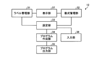
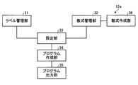
- FIG. 2 is a functional block diagram of the program creation device 12 according to the first embodiment.
- the program creation device 12 includes a label management unit 31, a mathematical expression management unit 32, a setting unit 33, a program creation unit 34, and a program output unit 35.
- the program creation device 12 further includes a display unit 37 and an input unit 38.
- the label management unit 31 manages input / output variables of a control program executed by the control device 13 that controls the device 14 to control the device 14 in association with variable labels. More specifically, the label management unit 31 combines the name of the device 14 and a list of variable labels corresponding to the input / output variables of the control program according to the configuration of the device 14 constituting the factory or various infrastructure facilities. Create an I / O label list.
- the input / output variables vary depending on the type of the device 14, but when the device 14 is a pump, driving horsepower, power consumption, and discharge amount are exemplified.
- the valve opening command and the valve opening are For example, when the device 14 is a fan, a rotation speed command is illustrated, and when the device 14 is an electric motor, a torque command and a rotation speed command are illustrated.
- the input / output variables are not limited to these.
- the label management unit 31 causes the display unit 37 to display the created input / output label list.
- the input / output variables of the control program include both variables given to the control program and variables output from the control program by calculation or calculation by the control program.
- the variable label is a character string attached to the data item of the input / output variable in order to distinguish the input / output variable.
- the mathematical expression management unit 32 manages mathematical expression frames constituting mathematical expressions used in the calculation program executed by the control device 13. More specifically, the formula management unit 32 causes the display unit 37 to display a list of formulas including a plurality of formulas. Formulas included in the list of formulas are used when the control device 13 performs calculation processing on input / output variables of the control program executed by the control device 13.
- the mathematical formula includes a mathematical formula frame.
- the mathematical expression frame is a mathematical expression described using operators, function names, and variables used in the calculation.
- the formula list is referred to as a formula frame list as appropriate.
- the setting unit 33 selects a variable label and a mathematical expression based on a command input via the input unit 38.
- the input unit 38 is a device for inputting commands and data to the program creation device 12.
- the program creation unit 34 creates a calculation program executed by the control device 13 based on the variable label and the selection information of the mathematical formula. Specifically, the program creation unit 34 selects a formula managed by the formula management unit 32, selects a variable label to be used in the selected formula from the variable labels managed by the label management unit 31, and selects the selected formula and variable label. Create a calculation program based on The program creation unit 34 creates a control program that is executed when the control device 13 controls the device 14.
- the selection information is information indicating which variable label and mathematical expression the user of the program creation device 12 has selected from a plurality of variable labels and a plurality of mathematical expressions.
- selection information is generated.
- the program output unit 35 outputs the created calculation program to the control program of the control device 13. Specifically, the program output unit 35 stores the created calculation program in the storage unit of the program creation device 12 as a part of the control program of the control device 13.
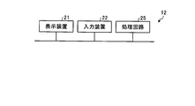
- the program creation device 12 includes a display device 21 that is a display unit 37, an input device 22 that is an input unit 38, a processor 23, and a memory 24.
- the display device 21 is a device that displays information, and is exemplified by a liquid crystal display, but is not limited thereto.
- the input device 22 is a device that inputs commands and data to the program creation device 12. Examples include, but are not limited to, a keyboard, a mouse, a pointing device, and a touch panel.
- the functions of the label management unit 31, the mathematical expression management unit 32, the setting unit 33, the program creation unit 34, and the program output unit 35 of the program creation device 12 are realized by the processor 23.
- the processor 23 is also referred to as a CPU (Central Processing Unit), a processing device, an arithmetic device, a microprocessor, a microcomputer, or a DSP (Digital Signal Processor).
- the functions of the label management unit 31, the mathematical expression management unit 32, the setting unit 33, the program creation unit 34, and the program output unit 35 are realized by software, firmware, or a combination of software and firmware.
- Software and firmware are described as programs and stored in the memory 24.
- the processor 23 reads out and executes the program stored in the memory 24, thereby realizing the functions of the label management unit 31, the mathematical expression management unit 32, the setting unit 33, the program creation unit 34, and the program output unit 35.
- These programs cause the computer to execute the procedure executed by the label management unit 31, the mathematical expression management unit 32, the setting unit 33, the program creation unit 34, and the program output unit 35 and the program creation method according to the first embodiment. It can be said.
- the memory 24 is a volatile or non-volatile semiconductor memory such as RAM (Random Access Memory), ROM (Read Only Memory), flash memory, EPROM (Erasable Programmable Read Only Memory), and EEPROM (Electrically Erasable Programmable Read Only Memory), Magnetic disks, flexible disks, optical disks, compact disks, mini disks, and DVDs (Digital Versatile Discs) are applicable.
- RAM Random Access Memory
- ROM Read Only Memory
- flash memory EPROM (Erasable Programmable Read Only Memory), and EEPROM (Electrically Erasable Programmable Read Only Memory), Magnetic disks, flexible disks, optical disks, compact disks, mini disks, and DVDs (Digital Versatile Discs) are applicable.
- the memory 24 includes a volatile storage device 24V such as a RAM and a nonvolatile storage device 24UV such as a ROM.
- the nonvolatile storage device 24UV is used when creating a program for realizing the functions of the label management unit 31, the mathematical formula management unit 32, the setting unit 33, the program creation unit 34, and the program output unit 35, and a control program and a calculation program. Setting data to be stored.
- a volatile storage device 24V is appropriately used as a work memory when the processor 23 executes processing.
- the functions of the label management unit 31, the mathematical expression management unit 32, the setting unit 33, the program creation unit 34, and the program output unit 35 of the program creation device 12 may be realized by a processing circuit 25 that is dedicated hardware.
- the processing circuit 25 corresponds to a single circuit, a composite circuit, a programmed processor, a parallel programmed processor, an ASIC (Application Specific Integrated Circuit), an FPGA (Field Programmable Gate Array), or a combination thereof. To do.
- Different processing circuits 25 may realize the functions of the label management unit 31, the mathematical expression management unit 32, the setting unit 33, the program creation unit 34, and the program output unit 35, or the functions may be combined into one processing circuit. 25 may be realized.
- Each function of the label management unit 31, the mathematical expression management unit 32, the setting unit 33, the program creation unit 34, and the program output unit 35 is partially realized by dedicated hardware, and partly realized by software or firmware. Good.
- the program creation device 12 realizes the functions of the label management unit 31, the formula management unit 32, the setting unit 33, the program creation unit 34, and the program output unit 35 by hardware, software, firmware, or a combination thereof. can do.
- the hardware configuration of the monitoring control device 11 is the same as that of the program creation device 12.
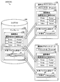
- FIG. 5 is a diagram showing the library 41 stored in the memory 24 of the program creation device 12 according to the first embodiment.
- 6 and 7 are diagrams illustrating an example of a screen displayed on the display device 21 by the program creation device 12 according to the first embodiment.
- FIG. 8 is a diagram showing a calculation program 48 and a calculation result label 49 created by the program creation device 12 according to the first embodiment.
- the library 41 stored in the nonvolatile storage device 24UV of the memory 24 includes a control program 42 and an input / output label list 43.
- the control program 42 is a program executed when the control device 13 shown in FIG.
- the input / output label list 43 is a list of variable labels LV corresponding to the input / output variables of the control program 42.
- the variable label LV is a character string such as Status or Power included in the input / output label list 43.
- the input / output variable represented by% 1 is the operating state of the device 14, and the input / output variable represented by% 2 represents the power consumption of the device 14.
- the input / output label list 43 stores variable labels LV and input / output variables in association with each other.
- the input / output label list 43 includes one or more variable labels and input / output variables.
- the library 41 includes control programs 42P and 42V for controlling the plurality of devices 14 and input / output label lists 43P and 43V for the plurality of devices 14.
- the library 41 includes a pump control program 42 ⁇ / b> P and a valve control program 42 ⁇ / b> V. When these are not distinguished, they are referred to as a control program 42.
- the control program 42 is prepared for each device 14. Devices 14 of the same type are controlled by the same control program 42.
- the control program 42 is versatile for the same type of device 14.
- the control program 42 is appropriately referred to as a general-purpose control program 42.
- the library 41 includes an input / output label list 43 ⁇ / b> P of a pump and an input / output label list 43 ⁇ / b> V of a valve (Valve). When these are not distinguished, they are referred to as an input / output label list 43.
- the input / output label list 43 is prepared for each device 14. The same input / output label list 43 is applied to the devices 14 of the same type. As described above, the input / output label list 43 is versatile for the same type of device 14.
- the input / output label list 43 is appropriately referred to as a general-purpose input / output label list 43.
- the processor 23 of the program creation device 12 causes the display device 21 to display a device configuration setting screen 21MS shown in FIG.
- the user operates the input device 22 in a state in which the device configuration setting screen 21MS is displayed on the display device 21, and inputs the device type MS and the device name MN in an inputable area of the device configuration setting screen 21MS.
- Configuration 44 is set.
- the device configuration 44 is a list of devices 14 included in the control system 1 shown in FIG. 1, and is represented by a combination of the device type MS and the name of the device 14, that is, the device name MN.
- the device name MN is used to distinguish each device 14 when there are a plurality of devices 14 of the same type.
- the processor 23 temporarily stores the set device configuration 44 in the storage area of the volatile storage device 24V of the memory 24.
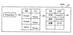
- the processor 23 causes the display device 21 to display the calculation program setting screen 21PS shown in FIG.
- the calculation program setting screen 21PS includes a calculation name 45, a label list 46, and a formula list 47.
- the calculation name 45 is a character string input to the program creation device 12 by the user, and becomes an output data name of the calculation program created by the program creation device 12.
- the label list 46 is a list in which the relationship between the device name MN of the device 14 included in the control system 1 and the variable label LV corresponding to the device name MN is described.
- the label management unit 31 configures a device name MN and a list of variable labels LV corresponding to input / output variables of the general-purpose control program 42 executed by the control device 13 that controls the device 14, that is, a general-purpose input / output label list 43. By combining them according to 44, a label list 46 is created. At this time, the label management unit 31 reads the device configuration 44 from the volatile storage device 24 ⁇ / b> V, and acquires the general-purpose input / output label list 43 of the device type MS corresponding to the device name MN of the device configuration 44 from the library 41. Then, the label management unit 31 combines the acquired general-purpose input / output label list 43 with the corresponding device name MN.
- the label management unit 31 creates the label list 46 by acquiring the general-purpose input / output label list 43 from the library 41 for all the device names MN included in the device configuration 44 and combining them to create a list.
- the label management unit 31 displays the created label list 46 on the display device 21.
- the formula list 47 is a list of formulas used in a calculation program executed by the control device 13.
- the formula list 47 is a list in which the formula name EN and the formula EXP are associated with each other.
- the mathematical expression list 47 is stored in the nonvolatile storage device 24UV of the memory 24.
- the expression EXP may be an expression frame, that is, an expression including an operator, a function name, and variables used in the calculation.
- the expression EXP may be one in which arithmetic calculation is described, or one in which logical calculation is described.
- the user selects the formula EXP included in the formula list 47 displayed on the calculation program setting screen 21PS, and inputs the character string indicating the selected formula EXP to the program creation device 12 via the input device 22.
- the setting unit 33 selects the formula EXP based on a command input via the input device 22, that is, a command for selecting the formula EXP.
- the program creation unit 34 creates a control program PGC. Specifically, the program creation unit 34 reads the general-purpose control program 42 of the device type MS corresponding to the device name MN from the library 41 and associates the device name MN with the above-described device name MN. The program creation unit 34 associates the device name MN with the general-purpose input / output label list 43 corresponding to the device name MN. In this way, the program creation unit 34 can identify the general-purpose control program 42 and the general-purpose input / output label list 43 as the individual control program 42 and the input / output label list 43. Further, the program creation unit 34 creates a calculation program 48 and a calculation result label 49 based on the calculation name 45 and the variable label LV and the selection information of the expression EXP. The calculation result label 49 is a calculation name 45, that is, a character string representing the calculation name 45.
- the program output unit 35 outputs the general-purpose control program 42 and the general-purpose input / output label list 43 associated with the device name MN to the control program PGC.
- the program output unit 35 outputs the calculation program 48 and the calculation result label 49 created by the program creation unit 34 to the control program PGC.
- the program creation device 12 creates a control program PGC for the control device 13 to control the device 14 included in the control system 1.
- the input / output variables of the control program PGC are also input / output variables of the general-purpose control program 42.
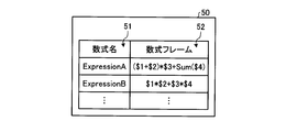
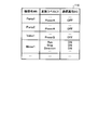
- FIG. 9 is a diagram showing the mathematical expression frame list 50 according to the first embodiment.
- the formula frame list 50 includes a formula frame 52.
- the formula frame list 50 is a list including a plurality of combinations of formula names 51 and formula frames 52.
- a mathematical expression frame 52 in which a mathematical expression name 51 is expressed by a character string of Expression A has an addition operator + and a multiplication operator * as operators, a total function Sum as a function, and a variable used in calculation. $ 1, $ 2, $ 3, and $ 4.
- a mathematical expression frame 52 in which a mathematical expression name 51 is expressed by a string of Expression B has an addition operator + and a multiplication operator * as operators, and $ 1, $ 2, $ 3 as variables used in the calculation. $ 4.
- the mathematical expression frame 52 is stored in the nonvolatile storage device 24UV of the memory 24 included in the program creation device 12.
- the variables used in the calculation will be referred to as mathematical variables as appropriate in the following.
- the formula frame list 50 may include a formula EXP.
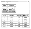
- FIG. 10 is a diagram showing a data configuration of the calculation program setting data 60 according to the first embodiment.
- the calculation program setting data 60 includes calculation name data 61, mathematical formula data 62, and a mathematical formula parameter list 63.
- the calculation name data 61 is information indicating the calculation name 45 input to the program creation device 12 by the user.
- the formula data 62 is information including at least one of the formula EXP and the formula frame 52 selected by the user.
- the formula parameter list 63 is information including formula data 62 and selection information of variables and variable labels LV used in the formula EXP.
- the formula parameter list 63 is configured in a data format that can select a plurality of formula variables for one formula variable, for example, an array, in order to calculate a function having a plurality of inputs.
- a plurality of formula variables for one formula variable for example, an array
- three formula variables $ 4, $ 4 [0], $ 4 [1], and $ 4 [2] are set.
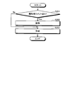
- FIG. 11 is a flowchart showing an example of processing in which the program creation device 12 according to the first embodiment creates a control program.
- This process is a program creation method according to the first embodiment.
- the processor 23 of the program creation device 12 causes the display device 21 to display a device configuration setting screen 21MS shown in FIG.
- the user operates the input device 22 in a state where the device configuration setting screen 21MS is displayed on the display device 21, and inputs the device type MS and the device name MN in the inputable area of the device configuration setting screen 21MS.
- 6 is input to the program creation device 12 to set the device configuration 44 shown in FIG.
- the processor 23 of the program creation device 12 receives this input, and temporarily stores the set device configuration 44 in the storage area of the volatile storage device 24V of the memory 24.
- step S102 the processor 23 causes the display device 21 to display the calculation program setting screen 21PS shown in FIG.
- the user inputs a character string that becomes the output data name of the calculation program to the calculation name 45 of the calculation program setting screen 21PS by the input device 22.
- the mathematical expression management unit 32 sets the input character string in the calculation name 45 of the calculation name data 61 of the calculation program setting data 60 shown in FIG.
- step S103 the mathematical formula management unit 32 displays the mathematical formula frame list 50 stored in the nonvolatile storage device 24UV of the memory 24 on the calculation program setting screen 21PS.
- the formula management unit 32 may also display the formula list 47 on the calculation program setting screen 21PS.
- the user selects at least one of the formula frame 52 and the formula EXP calculated by the calculation program 48 from the formula frame list 50.
- the formula list 47 is displayed on the calculation program setting screen 21PS, the user may select the formula EXP calculated by the calculation program 48 from the formula list 47, or by combining the selected formulas with the formula frame. 52 may be created.
- step S104 the setting unit 33 adds at least one of the selected formula frame 52 and the formula EXP to the formula data 62 of the calculation program setting data 60 and its formula. Name 51 is set.
- the setting unit 33 sets the selected formula EXP and its formula name EN in the formula data 62 of the calculation program setting data 60.
- step S105 the label management unit 31 combines the device name MN and the general-purpose input / output label list 43 corresponding to the input / output variables of the general-purpose control program 42 in accordance with the set device configuration 44, thereby providing a label list. 46 is created and displayed on the calculation program setting screen 21PS.
- Step S105 may be between step S101 and step S102.
- step S106 the setting unit 33 sets the selected variable label LV in the formula parameter list 63 in association with the formula variable.
- the program creation unit 34 specifies the device name MN for the general-purpose control program 42 and the general-purpose input / output label list 43 stored in the library 41 according to the device configuration 44, or specifies the device name MN. Given a unique name based on.
- step S108 the program creation unit 34 creates a calculation program 48 based on the mathematical expression parameter list 63 of the calculation program setting data 60.
- the calculation program 48 receives the specified variable label LV, that is, the variable label LV given the device name MN, and outputs the calculation result label 49 of the character string of the calculation name 45 set in the calculation name data 61. It is a program.
- a calculation program 48 is obtained by assigning the variable label LV associated with the mathematical expression parameter list 63 to the mathematical expression variable of the mathematical expression frame 52 and the mathematical expression EXP set in the mathematical expression data 62.
- the control device 13 executes the calculation program 48, the formula frame 52 and the formula EXP set in the formula data 62 are calculated using the variable label LV given the device name MN as the formula variable. This calculation result is associated with the calculation result label 49.
- step S109 the program output unit 35 sends the general-purpose control program 42, the general-purpose input / output label list 43, the created calculation program 48, and the created calculation result label 49 associated with the device name MN to the control program PGC. Output.
- the program creation device 12 creates the control program PGC.
- the program creation device 12 stores at least one of the formula frame 52 and the formula EXP used for the calculation program 48 and the variable label LV in the memory 24, and at least the formula frame 52 and the formula EXP used by the calculation program 48.
- One and the variable label LV are selected by the user.
- the program creation device 12 creates the calculation program 48 based on the selection information of at least one of the formula frame 52 and the formula EXP, the variable label LV, and the configuration of the device 14 of the control system 1. That is, the program creation device 12 causes the user to select the formula frame 52 and the formula EXP stored in the memory 24 in advance and the variable label LV to be a formula variable, and creates the calculation program 48 based on the selection result.
- the program creation device 12 can suppress the man-hours for creating the program executed by the control device 13, and can suppress a mistake in the program due to a user input error.
- the formula frame 52 and the formula EXP are elements constituting the calculation program 48, and formula variables can be set according to the configuration of the device 14 of the control system 1. Since the program creation device 12 stores a plurality of mathematical expression frames 52 and mathematical expressions EXP in the memory 24, it can correspond to various calculation programs 48. For this reason, the program creation apparatus 12 can respond to the configuration of various devices 14 and is highly versatile. Unlike the C language, it is difficult to easily create the calculation program 48 for the ladder program used in the PLC, but the program creation device 12 can easily create the calculation program 48 in the ladder program and make mistakes. Can be suppressed.
- FIG. FIG. 12 is a functional block diagram of the program creation device 12a according to the second embodiment.
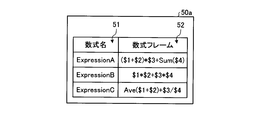
- FIG. 13 is a diagram showing the mathematical expression frame list 50a according to the second embodiment.
- the program creation device 12a includes a formula creation unit 36 in addition to the program creation device 12 of the first embodiment. Other configurations are the same as those in the first embodiment.
- the hardware configuration of the program creation device 12a is the same as that of the program creation device 12 of the first embodiment.
- the formula generator 36 is realized by the processor 23 and the memory 24 shown in FIG. 3 or the processing circuit 25 shown in FIG.
- the formula creation unit 36 creates or edits the formula frame 52 according to the input, more specifically, the user's input.
- the formula creating unit 36 may create or edit the formula EXP.
- the formula management unit 32 adds the formula frame 52 or the formula EXP created or edited by the formula creation unit 36 to the formula frame list 50a.
- a formula frame 52 having a formula name 51 represented by a character string ExpressionC is added to the formula frame list 50a.
- the formula frame 52 or the formula EXP held in the formula frame list 50a is edited using the input device 22 shown in FIG. 3 or FIG.
- the formula frame 52 or the formula EXP is created.
- the formula creating unit 36 edits the formula frame 52 or the formula EXP according to the acquired command, or creates a new formula frame 52 or Or create an expression EXP.
- the formula management unit 32 writes the formula frame 52 or the formula EXP that has been edited to the formula frame list 50a, or writes the newly created formula frame 52 formula EXP to the formula frame list 50a.
- the formula creation unit 36 displays the formula frame 52 or the formula EXP to be edited on the screen of the display device 21. In this way, the user can easily edit the formula frame 52 or the formula EXP.
- the formula management unit 32 includes the formula frame 52 and the formula EXP defined by the user as candidates for the formula frame 52 and the formula EXP used in the calculation program 48 on the calculation program setting screen 21PS.
- the list 50a can be displayed.
- the setting unit 33 can set this in the formula data 62.
- the program creation unit 34 can create a calculation program 48 using the mathematical expression frame 52 and the mathematical expression EXP defined by the user. As a result, the program creation device 12a can create the calculation program 48 for performing the calculation set by the user.
- the label management unit 31 of the above-described program creation devices 12 and 12a filters and displays a plurality of variable labels LV on the display device 21 and sorts and displays them on the display device 21. Do at least one. For filtering and sorting the variable label LV, at least one of the device name MN, the name of the variable label LV, and the device type MS is used.
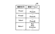
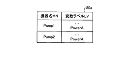
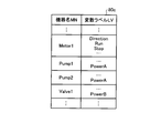
- FIG. 14 is a diagram showing a label list 80 according to the third embodiment.
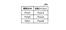
- 15 and 16 are diagrams showing label lists 80a and 80b obtained by filtering the label list 80 according to the third embodiment.
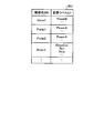
- 17 and 18 are diagrams showing label lists 80c and 80d obtained by sorting the label list 80 according to the third embodiment. Next, examples of filtering and sorting will be described.
- the label management unit 31 filters the label list 80 shown in FIG. 14 with the device type MS Pump, thereby extracting the variable label LV with the device type MS Pump, and the label list 80a shown in FIG. create.
- the label management unit 31 causes the display device 21 to display the created label list 80a when the user selects the variable label LV.
- the device type MS is a character string portion excluding the number of the device name MN.
- the label management unit 31 extracts the variable label LV including “Power” in the name by filtering the label list 80 illustrated in FIG. 14 with the name of the variable label LV including “Power”, and is illustrated in FIG.
- a label list 80b is created.
- the label management unit 31 displays the created label list 80b on the display device 21 when the user selects the variable label LV.
- the label management unit 31 creates the label list 80c shown in FIG. 17 by sorting the label list 80 shown in FIG. 14 in ascending order of the first character of the character string indicating the device name MN.
- the label management unit 31 causes the display device 21 to display the created label list 80c when the user selects the variable label LV.
- the label management unit 31 creates the label list 80d shown in FIG. 18 by sorting the label list 80 shown in FIG. 14 in descending order of the first character of the character string indicating the device name MN.
- the label management unit 31 causes the display device 21 to display the created label list 80d when the user selects the variable label LV.
- the label management unit 31 can narrow down the items in the label list 80 and change the arrangement. As a result, the label management unit 31 can change the label list 80 into a form that is easy for the user to select, so that it is possible to improve convenience when the user selects the variable label LV, and the variable label LV. The selection error can be reduced.
- FIG. 19 is a diagram showing control programs PGCb and PGCa according to the fourth embodiment.
- the control programs 91b and 91a, the calculation programs 98b and 98a, and the label lists 92b and 92a included in the control programs PGCb and PGCa created by the program creation unit 34 of the program creation devices 12 and 12a described above include Comment CM can be added.
- the comment CM also includes an identifier indicating that it has been created by the program creation unit 34. Therefore, the control program 91b, 91a, the calculation program 98b, 98a, and the label list 92b, 92a can be given an identifier indicating that the program has been created by the program creation unit 34.
- this identifier is referred to as an identification comment as appropriate.
- the identification comment is shown in FIG. ! ].
- the program output unit 35 uses an identification comment [! ! ],
- the control programs 91b and 91a created by the program creation unit 34 can be distinguished from the user program 95 which is a control program created by the user.
- the calculation programs 98b and 98a and the label lists 92b and 92a are distinguished from a user calculation program which is a calculation program created by the user and a user label list 92i which is a label list created by the user.
- the program output unit 35 of the program creation devices 12 and 12a uses the identification comment [! ! ] Is deleted from the control program PGCb, the control program 91b, the calculation program 98b, and the label list 92b.
- the user program 95 and the user label list 92i remain in the control program PGCi after deletion. If the user calculation program is included in the control program PGCb, the user calculation program remains in the deleted control program PGCi.
- the program output unit 35 outputs the new control program 91a, the calculation program 98a, and the label list 92a created by the program creation unit 34 to the control program PGCi in which the user program 95 and the user label list 92i remain. In this way, the program creation devices 12 and 12a create a new control program PGCa.
- FIG. 20 is a flowchart showing a procedure of processing executed by the program creation devices 12 and 12a in the fourth embodiment.
- the program output unit 35 adds an identification comment [! To the already created control program PGCb. ! ] (Yes in step S201), an identification comment [! ! ] Is deleted from the control program PGCb, the control program 91b, the calculation program 98b, and the label list 92b.
- the program output unit 35 creates a new control program PGCa using the deleted control program PGCi.
- the program output unit 35 adds an identification comment [!] To the already created control program PGCb. !
- step S201 a new control program 91a, a calculation program 98a and a label list 92a created by the program creation unit 34 are output to the control program PGCb already created in step S203, A new control program PGCa is created. In this way, the program creation devices 12 and 12a create a new control program PGCa.
- the program creation devices 12 and 12a can create a new control program PGCa by using the already created control program PGCb.
- the program creation devices 12 and 12a delete the existing calculation program 98b and the control program 91b to make a new calculation program 98b and a control program 98b. For this reason, the program creation devices 12 and 12a can easily change the existing calculation program 98b and the control program 91b.
- FIG. FIG. 21 is a block diagram showing the application source project data 104, the application destination project data 107, and the library 100 stored in the nonvolatile storage device 24UV according to the fifth embodiment.
- the program creation devices 12 and 12a store the template 101 in which the variable label LV used for generating the calculation program 48, the mathematical expression frame 52, and the configuration of the device 14 are associated.
- the storage unit is a memory 24, and more specifically, a nonvolatile storage device 24UV.
- the formula frame 52 of the template 101 may be a formula EXP.
- the user creates all the data required by the program creation devices 12 and 12a as the application project data 104 in order to create the control program PGC.
- the application source project data 104 is stored in the nonvolatile storage device 24UV of the memory 24.
- the setting unit 33 stores the device configuration 105 and the calculation program setting data 106 input to the application source project data 104 as the template 101 of the library 100.
- the template 101 includes a device configuration 102 and calculation program setting data 103.
- the created template 101 is written into the library 100 stored in the nonvolatile storage device 24UV of the memory 24.
- the device configurations 105 and 102 are combinations of the device type MS and the device name MN, and are the same as the device configuration 44 described in the first embodiment.
- the calculation program setting data 106 and 103 have the same configuration as the calculation program setting data 60 described in the first embodiment.
- the setting unit 33 compares the application project data 107 with the template 101. As a result of the comparison, when the device configuration 102 of the template 101 and the device configuration 108 of the application project data 107 are the same, the setting unit 33 converts the calculation program setting data 103 of the template 101 into the calculation program setting data 109 of the application project data 107. Read from the library 100. Then, the setting unit 33 sets the read calculation program setting data 103 of the template 101 in the calculation program setting data 109 of the application project data 107.
- the information regarding the setting of the calculation program 48 once input to the program creation devices 12 and 12a, more specifically, the calculation program setting data 103 can be reused.
- the input effort is reduced.
- the configuration disclosed in the fifth embodiment can be appropriately applied to the following embodiments.
- FIG. 22 is a diagram showing a label list 110 according to the sixth embodiment.
- the label list 110 is obtained by adding a communication attribute BG to the label list 46 according to the first to fifth embodiments.
- the communication attribute BG is information indicating whether or not to transmit the variable label LV used in the calculation program 48 created by the program creation unit 34 to the monitoring control device 11.
- the communication attribute BG is added to the label list 46, and the label management unit 31 assigns the communication attribute BG to the variable label LV, so that the monitoring control device 11 transmits and receives the variable label LV. Allow setting whether or not.
- the program creation devices 12 and 12 a transmit the variable label LV to the monitoring control device 11.
- the program creation devices 12 and 12a do not transmit the variable label LV to the monitoring control device 11.
- transmission / reception of unnecessary information can be reduced by the communication attribute BG, the performance of data communication between the control device 13 and the monitoring control device 11 can be improved.
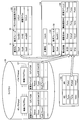
- FIG. 23 is a diagram showing the mathematical expression frame list 123 and the calculation program setting data 126 according to the seventh embodiment.
- the formula frame list 123 according to the seventh embodiment includes a parameter selection condition CDC that is information for selecting the variable label LV used in the formula frame 52 and the formula EXP in the formula frame list 50 according to the first embodiment. It is added. That is, the formula frame list 123 includes the parameter selection condition CDC. Specifically, the formula frame list 123 is a list including combinations of the formula name 51, the formula frame 52, and the parameter selection condition CDC. The formula frame 52 in the formula frame list 123 may be a formula EXP.
- the mathematical expression frame list 123 is stored in the nonvolatile storage device 24UV of the memory 24 that is a storage unit.
- the parameter selection condition CDC includes names of comment CM, variable label LV, and variable label LV, but is not limited thereto.
- the label list 121 stored in the library 120 is obtained by adding a comment CM to the input / output label list 43 according to the first embodiment.
- a comment CM can be attached to the variable label LV.
- the setting unit 33 When the formula frame 52 or the formula EXP is selected by the user from the formula frame list 123, the setting unit 33 adds the selected formula frame 52 or formula EXP and its formula name 51 to the formula data 124 of the calculation program setting data 126. Set. Next, the setting unit 33 uses the parameter selection condition CDC corresponding to the selected formula frame 52 or the formula EXP and the formula name 51 to set the variables in the label list 121 stored in the library 120 based on the device configuration 122. A keyword search is performed on at least one of the name of the label LV and the comment CM. Then, the setting unit 33 selects the variable label LV corresponding to the keyword from the label list 121 and sets it in the formula parameter list 125 as a formula variable used in the formula frame 52 or the formula EXP.
- the parameter selection condition CDC associated with the formula frame 52 is “comment”. “Comment” is an item to be searched for keywords.
- the setting unit 33 acquires “comment”, which is the parameter selection condition CDC corresponding to the selected formula frame 52 in which the formula name 51 is represented by the character string ExpA, from the formula frame list 123.
- the setting unit 33 searches the comment CM in the label list 121 of the device type MS corresponding to the device name MN with reference to the device configuration 122.
- the device name MN is Pump1
- the setting unit 33 performs a keyword search for the comment CM in the pump (Pump) label list 121.
- the keyword used for the keyword search includes the formula name 51 and the operator, function name, and formula variable included in the formula frame 52 or the formula EXP.
- the setting unit 33 can select the variable label LV represented by the character string Power. .
- the keyword is the formula name 51 in the formula frame list 123.
- the setting unit 33 sets the variable label LV represented by the character string Power selected by the search to the variable label LV of the mathematical expression parameter list 125 as a mathematical variable corresponding to the device name MN represented by the character string Pump1.
- the parameter selection condition CDC associated with the formula frame 52 is “variable label”.
- the setting unit 33 acquires “variable label”, which is the parameter selection condition CDC corresponding to the selected formula frame 52 in which the formula name 51 is represented by the character string ExpB, from the formula frame list 123.
- the setting unit 33 refers to the device configuration 122 and performs a keyword search for the variable label LV of the label list 121 of the device type MS corresponding to the device name MN.
- the device name MN is Pump1
- the setting unit 33 performs a keyword search for the variable label LV of the pump label list 121.
- the keyword used for the keyword search includes the formula name 51 and the operator, function name, and formula variable included in the formula frame 52 or the formula EXP.
- the setting unit 33 may select the variable label LV represented by the character string ExpB_Param1. it can.
- the setting unit 33 sets the variable label LV represented by the character string Power selected by the search as the variable label LV of the formula parameter list 125 as the formula variable used in the formula frame 52 corresponding to the character string Exp.
- the setting unit 33 sets the variable label LV selected by performing a keyword search for the item in the label list 121 corresponding to the parameter selection condition CDC to the mathematical expression frame 52 set in the mathematical expression data 124 of the calculation program setting data 126 or It is set as a formula variable used in the formula EXP.
- the user of the program creation devices 12 and 12a can create the calculation program 48 only by selecting the formula frame 52 or the formula EXP.
- the configuration described in the above embodiment shows an example of the contents of the present invention, and can be combined with another known technique, and can be combined with other configurations without departing from the gist of the present invention. It is also possible to omit or change the part.
Landscapes
- Physics & Mathematics (AREA)
- General Physics & Mathematics (AREA)
- Engineering & Computer Science (AREA)
- Automation & Control Theory (AREA)
- Programmable Controllers (AREA)
Abstract
制御装置が実行するプログラムを作成する工数を抑制することを目的とする。プログラム作成装置(12)は、ラベル管理部(31)と、数式管理部(32)と、プログラム作成部(34)とを含む。ラベル管理部(31)は、機器を制御する制御装置が実行する制御プログラムの入出力変数を変数ラベルと対応付けて管理する。数式管理部(32)は、制御装置が実行する計算プログラムに使用される数式を管理する。プログラム作成部(34)は、数式管理部が管理する数式を選択し、選択した数式で使用する変数ラベルをラベル管理部が管理する変数ラベルから選択し、選択した数式及び変数ラベルに基づいて計算プログラムを作成する。
Description
本発明は、工場及び各種の社会インフラ設備で用いられる機器を制御する制御装置が実行するプログラムを作成するためのプログラム作成装置、プログラム作成方法及びプログラムに関する。
工場及び各種の社会インフラ設備で用いられる機器に動作指示を送る制御プログラムは、機器を制御する制御装置内で実行される。制御システムが多くの機器から構成される場合、制御プログラムが作成されるにあたっては、ユーザが多数の入出力変数のラベル、すなわち入出力変数のデータの項目に付される文字列の中から必要とするラベルを探し、そのラベルから所望のデータを計算するプログラムを手作業で作成するため、多くの手間を要していた。
プログラムを手作業で作成する手間を軽減する技術として、特許文献1には、物理データを使用して演算/シーケンス処理した定数・変数・関数・履歴データ・平均値等の論理データにタグを割り付け、物理タグと同様の取扱いで、計装シーケンサ等に組み込まれるデシジョンテーブルやプロダクションルールの記述(プログラミング)に利用できるようにする監視制御システムが記載されている。
特許文献1に記載されている技術は、論理データに割り付けられる論理タグをユーザが定義する必要がある。このため、プログラムを作成する工数の増加を招くことがある。
本発明は、上記に鑑みてなされたものであって、制御装置が実行するプログラムを作成する工数を抑制することを目的とする。
上述した課題を解決し、目的を達成するために、本発明に係るプログラム作成装置は、ラベル管理部と、数式管理部と、プログラム作成部とを含む。ラベル管理部は、機器を制御する制御装置が実行する制御プログラムの入出力変数を変数ラベルと対応付けて管理する。数式管理部は、制御装置が実行する計算プログラムに使用される数式を管理する。プログラム作成部は、数式管理部が管理する数式を選択し、選択した数式で使用する変数ラベルをラベル管理部が管理する変数ラベルから選択し、選択した数式及び変数ラベルに基づいて計算プログラムを作成する。
本発明に係るプログラム作成装置は、制御装置が実行するプログラムを作成する工数を抑制することができるという効果を奏する。
以下に、本発明の実施の形態に係るプログラム作成装置、プログラム作成方法及びプログラムを図面に基づいて詳細に説明する。なお、この実施の形態によりこの発明が限定されるものではない。
実施の形態1.
図1は、実施の形態1に係るプログラム作成装置によって作成された制御プログラムが適用される制御システム1の一例を示す図である。実施の形態1に係る制御システム1は、SCADA(Supervisory Control And Data Acquisition)と呼ばれる監視制御システムである。監視制御システムは、産業制御システムの一種であり、コンピュータによるシステム監視とプロセス制御とを行う。監視制御システムの対象は、工場の生産工程及び各種のインフラ設備に関するものである。制御システム1は、監視制御システムに限定されるものではない。
図1は、実施の形態1に係るプログラム作成装置によって作成された制御プログラムが適用される制御システム1の一例を示す図である。実施の形態1に係る制御システム1は、SCADA(Supervisory Control And Data Acquisition)と呼ばれる監視制御システムである。監視制御システムは、産業制御システムの一種であり、コンピュータによるシステム監視とプロセス制御とを行う。監視制御システムの対象は、工場の生産工程及び各種のインフラ設備に関するものである。制御システム1は、監視制御システムに限定されるものではない。
制御システム1は、工場及び各種のインフラ設備において、これらを構成する機器14を制御するために用いられる。制御システム1は、監視制御装置11、プログラム作成装置12、制御装置13、機器14及び通信回線15を含む。監視制御装置11は、制御装置13を介して機器14を制御するとともに、制御装置13から機器14の状態に関する情報を取得して、機器14を監視する。
プログラム作成装置12は、制御装置13が機器14を制御するために実行するコンピュータプログラムを作成する。実施の形態1において、監視制御装置11及びプログラム作成装置12は、パーソナルコンピュータのような汎用のコンピュータである。実施の形態1において、監視制御装置11及びプログラム作成装置12はそれぞれ別個のコンピュータであるが、両者は同一のコンピュータで実現されてもよい。すなわち、1台のコンピュータが、監視制御装置11及びプログラム作成装置12を実現してもよい。
実施の形態1において、制御装置13は、プログラマブルコントローラ(Programmable Logic Controllers(PLC))である。プログラマブルコントローラは、JIS(日本工業規格) B 3502:2011により規定されたものである。制御装置13は、機器14を制御する装置であればよく、プログラマブルコントローラに限定されるものではない。
制御装置13は、通信回線15を介して機器14と接続されている。実施の形態1において、制御装置13は、プログラム作成装置12によって作成されたプログラムを実行することにより、機器14を制御する。機器14は、工場の生産工程及び各種のインフラ設備を構成する機器である。機器14としては、工作機械、組立装置、搬送装置、仕分装置、室外機、室内機、ポンプ、バルブ及びファンが例示されるが、これらに限定されるものではない。実施の形態1において、1台の制御装置13が複数の機器14を制御するが、これに限定されない。1台の制御装置13が1台の機器14を制御してもよい。この場合、制御装置13と機器14とがそれぞれ1台のみであってもよいし、制御装置13と機器14とがそれぞれ複数かつ同数であってもよい。
図2は、実施の形態1に係るプログラム作成装置12の機能ブロック図である。プログラム作成装置12は、ラベル管理部31、数式管理部32、設定部33、プログラム作成部34及びプログラム出力部35を含む。プログラム作成装置12は、さらに表示部37及び入力部38を含む。ラベル管理部31は、機器14を制御する制御装置13が機器14を制御するために実行する制御プログラムの入出力変数を変数ラベルと対応付けて管理する。より詳細には、ラベル管理部31は、工場又は各種のインフラ設備を構成する機器14の構成に応じて、機器14の名前と制御プログラムの入出力変数に対応する変数ラベルのリストとを組み合わせた入出力ラベルリストを作成する。
入出力変数は、機器14の種類によって異なるが、機器14がポンプである場合、駆動馬力、消費電力及び吐出量が例示され、機器14がバルブである場合、バルブ開度指令及びバルブ開度が例示され、機器14がファンである場合、回転速度指令が例示され、機器14が電動機である場合、トルク指令及び回転速度指令が例示される。入出力変数はこれらに限定されるものではない。ラベル管理部31は、作成した入出力ラベルリストを、表示部37に表示させる。
実施の形態1において、制御プログラムの入出力変数とは、制御プログラムに与えられる変数と、制御プログラムによる演算又は計算により制御プログラムから出力される変数との両方を含む。変数ラベルとは、入出力変数を区別するために、入出力変数のデータの項目に付される文字列である。
数式管理部32は、制御装置13が実行する計算プログラムに使用される数式を構成する数式フレームを管理する。より詳細には、数式管理部32は、複数の数式を含む数式のリストを表示部37に表示させる。数式のリストに含まれる数式は、制御装置13が実行する制御プログラムの入出力変数を、制御装置13が計算処理する際に用いられる。実施の形態1において、数式は、数式フレームを含む。実施の形態1において、数式フレームとは、演算子、関数名及び計算で使用する変数を用いて記述された数式である。以下において、数式のリストを、適宜数式フレームリストと称する。
設定部33は、入力部38を介して入力された指令に基づいて、変数ラベル及び数式を選択する。入力部38は、プログラム作成装置12へ指令及びデータを入力するための装置である。
プログラム作成部34は、変数ラベル及び数式の選択情報を元に、制御装置13が実行する計算プログラムを作成する。詳細には、プログラム作成部34は、数式管理部32が管理する数式を選択し、選択した数式で使用する変数ラベルをラベル管理部31が管理する変数ラベルから選択し、選択した数式及び変数ラベルに基づいて計算プログラムを作成する。また、プログラム作成部34は、制御装置13が機器14を制御する際に実行する制御プログラムを作成する。
選択情報は、プログラム作成装置12のユーザが、複数の変数ラベル及び複数の数式から、どの変数ラベル及び数式を選択したかを示す情報である。ラベル管理部31が作成したラベルリスト及び数式管理部32が作成した数式フレームリストから、ユーザが変数ラベル及び数式を選択すると、選択情報が生成される。
プログラム出力部35は、作成した計算プログラムを、制御装置13の制御プログラムに出力する。詳細には、プログラム出力部35は、作成した計算プログラムを、プログラム作成装置12の記憶部に制御装置13の制御プログラムの一部として記憶させる。
図3及び図4は、実施の形態1に係るプログラム作成装置12のハードウェア構成を示す図である。プログラム作成装置12は、表示部37である表示装置21、入力部38である入力装置22、プロセッサ23及びメモリ24を含む。表示装置21は、情報を表示する装置であり、液晶ディスプレイが例示されるがこれに限定されるものではない。入力装置22は、プログラム作成装置12に指令及びデータを入力する装置である。キーボード、マウス、ポインティングデバイス及びタッチパネルが例示されるが、これらに限定されるものではない。
プログラム作成装置12が有するラベル管理部31、数式管理部32、設定部33、プログラム作成部34及びプログラム出力部35の機能は、プロセッサ23によって実現される。プロセッサ23は、CPU(Central Processing Unit:中央処理装置)、処理装置、演算装置、マイクロプロセッサ、マイクロコンピュータ、又はDSP(Digital Signal Processor)ともいう。
この場合、ラベル管理部31、数式管理部32、設定部33、プログラム作成部34及びプログラム出力部35の機能は、ソフトウェア、ファームウェア、又はソフトウェアとファームウェアとの組合せにより実現される。ソフトウェア及びファームウェアはプログラムとして記述され、メモリ24に記憶される。プロセッサ23は、メモリ24に記憶されたプログラムを読み出して実行することにより、ラベル管理部31、数式管理部32、設定部33、プログラム作成部34及びプログラム出力部35の機能を実現する。
これらのプログラムは、ラベル管理部31、数式管理部32、設定部33、プログラム作成部34及びプログラム出力部35が実行する手順及び実施の形態1に係るプログラム作成方法をコンピュータに実行させるものであるともいえる。
メモリ24は、RAM(Random Access Memory)、ROM(Read Only Memory)、フラッシュメモリー、EPROM(Erasable Programmable Read Only Memory)、及びEEPROM(Electrically Erasable Programmable Read Only Memory)といった揮発性又は不揮発性の半導体メモリ、磁気ディスク、フレキシブルディスク、光ディスク、コンパクトディスク、ミニディスク、及びDVD(Digital Versatile Disc)が該当する。
実施の形態1において、メモリ24は、RAMのような揮発性記憶装置24Vと、ROMのような不揮発性記憶装置24UVとを有する。不揮発性記憶装置24UVには、ラベル管理部31、数式管理部32、設定部33、プログラム作成部34及びプログラム出力部35の機能を実現するためのプログラムと、制御プログラム及び計算プログラムの作成時に用いられる設定データとが記憶される。プロセッサ23が処理を実行する際のワークメモリとして、揮発性記憶装置24Vが適宜使用される。
プログラム作成装置12が有するラベル管理部31、数式管理部32、設定部33、プログラム作成部34及びプログラム出力部35の機能は、専用のハードウェアである処理回路25によって実現されてもよい。この場合、処理回路25は、単一回路、複合回路、プログラム化したプロセッサ、並列プログラム化したプロセッサ、ASIC(Application Specific Integrated Circuit)、FPGA(Field Programmable Gate Array)、又はこれらを組み合わせたものが該当する。ラベル管理部31、数式管理部32、設定部33、プログラム作成部34及びプログラム出力部35のそれぞれの機能を異なる処理回路25が実現してもよいし、それぞれの機能をまとめて1つの処理回路25が実現してもよい。
ラベル管理部31、数式管理部32、設定部33、プログラム作成部34及びプログラム出力部35の各機能は、一部が専用のハードウェアで実現され、一部がソフトウェア又はファームウェアで実現されてもよい。このように、プログラム作成装置12は、ハードウェア、ソフトウェア、ファームウェア又はこれらの組合せによって、ラベル管理部31、数式管理部32、設定部33、プログラム作成部34及びプログラム出力部35の各機能を実現することができる。監視制御装置11のハードウェア構成は、プログラム作成装置12と同様である。
図5は、実施の形態1に係るプログラム作成装置12のメモリ24が記憶するライブラリ41を示す図である。図6及び図7は、実施の形態1に係るプログラム作成装置12が表示装置21に表示する画面の一例を示す図である。図8は、実施の形態1に係るプログラム作成装置12によって作成された計算プログラム48及び計算結果ラベル49を示す図である。
メモリ24の不揮発性記憶装置24UV内に記憶されるライブラリ41は、制御プログラム42及び入出力ラベルリスト43を含む。制御プログラム42は、図1に示される制御装置13が機器14を制御する際に実行するプログラムである。入出力ラベルリスト43は、制御プログラム42の入出力変数に対応する変数ラベルLVのリストである。実施の形態1において、変数ラベルLVは、入出力ラベルリスト43に含まれる、Status,Powerといった文字列である。実施の形態1において、%1で表される入出力変数は機器14の運転状態であり、%2で表される入出力変数は機器14の消費電力を示す。入出力ラベルリスト43は、変数ラベルLVと入出力変数とを対応付けて格納さする。入出力ラベルリスト43は、1以上の変数ラベル及び入出力変数を含む。
実施の形態1においては、複数の機器14を制御するための制御プログラム42P,42V及び複数の機器14の入出力ラベルリスト43P,43Vがライブラリ41に含まれている。図5に示される例では、ポンプ(Pump)の制御プログラム42Pと、バルブ(Valve)の制御プログラム42Vとがライブラリ41に含まれる。これらを区別しない場合、制御プログラム42と称する。制御プログラム42は、機器14毎に用意される。同じ種別の機器14は、同じ制御プログラム42によって制御される。このように、制御プログラム42は、同じ種別の機器14に対して汎用性を有する。以下において、制御プログラム42を、適宜、汎用制御プログラム42と称する。
図5に示される例では、ポンプ(Pump)の入出力ラベルリスト43Pと、バルブ(Valve)の入出力ラベルリスト43Vとがライブラリ41に含まれる。これらを区別しない場合、入出力ラベルリスト43と称する。入出力ラベルリスト43は、機器14毎に用意される。同じ種別の機器14は、同じ入出力ラベルリスト43が適用される。このように、入出力ラベルリスト43は、同じ種別の機器14に対して汎用性を有する。以下において、入出力ラベルリスト43を、適宜、汎用入出力ラベルリスト43と称する。
プログラム作成装置12がプログラムを作成する場合、プログラム作成装置12のプロセッサ23は、図6に示される機器構成設定画面21MSを表示装置21に表示させる。ユーザは、機器構成設定画面21MSが表示装置21に表示された状態で入力装置22を操作し、機器構成設定画面21MSの入力可能な領域に機器種別MS及び機器名MNを入力することにより、機器構成44を設定する。機器構成44は、図1に示される制御システム1に含まれる機器14の一覧であり、機器種別MSと機器14の名前、すなわち機器名MNとの組合せで表される。機器名MNは、同一種類の機器14が複数存在する場合、それぞれの機器14を区別するためのものである。機器構成44が設定されたら、プロセッサ23は、設定された機器構成44を、メモリ24の揮発性記憶装置24Vの記憶領域に一時的に記憶させる。
プロセッサ23は、図7に示される計算プログラム設定画面21PSを表示装置21に表示させる。計算プログラム設定画面21PSは、計算名45と、ラベルリスト46と、数式リスト47とを含む。計算名45は、ユーザによってプログラム作成装置12に入力される文字列であり、プログラム作成装置12が作成する計算プログラムの出力データ名となる。ラベルリスト46は、制御システム1に含まれる機器14の機器名MNと、機器名MNに対応する変数ラベルLVとの関係が記述されたリストである。
ラベル管理部31は、機器名MNと、機器14を制御する制御装置13が実行する汎用制御プログラム42の入出力変数に対応する変数ラベルLVのリスト、すなわち汎用入出力ラベルリスト43とを機器構成44に応じて組み合わせることにより、ラベルリスト46を作成する。このとき、ラベル管理部31は、揮発性記憶装置24Vから機器構成44を読み出し、機器構成44の機器名MNに対応する機器種別MSの汎用入出力ラベルリスト43を、ライブラリ41から取得する。そしてラベル管理部31は、取得した汎用入出力ラベルリスト43とこれに対応する機器名MNとを組み合わせる。ラベル管理部31は、機器構成44に含まれるすべての機器名MNに対して汎用入出力ラベルリスト43をライブラリ41から取得して組み合わせて一覧を作成することにより、ラベルリスト46を作成する。ラベル管理部31は、作成したラベルリスト46を、表示装置21に表示させる。
数式リスト47は、制御装置13が実行する計算プログラムに使用される数式のリストである。数式リスト47は、数式名ENと数式EXPとが対応付けられたリストである。数式リスト47は、メモリ24の不揮発性記憶装置24UVに記憶されている。前述したように、数式EXPは、数式フレーム、すなわち演算子、関数名及び計算で使用される変数を含む数式であってもよい。数式EXPは、算術計算が記述されたものであってもよいし、論理計算が記述されたものであってもよい。
ユーザは、計算プログラム設定画面21PSに表示された数式リスト47に含まれる数式EXPを選択し、入力装置22を介して選択した数式EXPを示す文字列をプログラム作成装置12に入力する。設定部33は、入力装置22を介して入力された指令、すなわち数式EXPを選択する指令に基づいて数式EXPを選択する。
プログラム作成部34は、制御プログラムPGCを作成する。詳細には、プログラム作成部34は、機器名MNに対応する機器種別MSの汎用制御プログラム42をライブラリ41から読み出して前述の機器名MNを対応付ける。また、プログラム作成部34は、機器名MNに対応する汎用入出力ラベルリスト43に前述の機器名MNと対応付ける。このようにして、プログラム作成部34は、汎用制御プログラム42及び汎用入出力ラベルリスト43を、個別の制御プログラム42及び入出力ラベルリスト43として識別できるようにする。また、プログラム作成部34は、計算名45と、変数ラベルLV及び数式EXPの選択情報とに基づき、計算プログラム48及び計算結果ラベル49を作成する。計算結果ラベル49は計算名45、すなわち計算名45を表す文字列である。
プログラム出力部35は、機器名MNと対応付けられた汎用制御プログラム42及び汎用入出力ラベルリスト43を制御プログラムPGCに出力する。また、プログラム出力部35は、プログラム作成部34によって作成された計算プログラム48及び計算結果ラベル49を制御プログラムPGCに出力する。このようにして、プログラム作成装置12は、制御装置13が制御システム1に含まれる機器14を制御するための制御プログラムPGCを作成する。制御プログラムPGCの入出力変数は、汎用制御プログラム42の入出力変数でもある。
図9は、実施の形態1に係る数式フレームリスト50を示す図である。数式フレームリスト50は、数式フレーム52を含む。詳細には、数式フレームリスト50は、数式名51と数式フレーム52との組合せを複数含むリストである。数式名51がExpressionAの文字列で表される数式フレーム52は、演算子として加算の演算子+、乗算の演算子*を有し、関数として合計の関数Sumを有し、計算で使用する変数として$1,$2,$3,$4を有する。数式名51がExpressionBの文字列で表される数式フレーム52は、演算子として加算の演算子+、乗算の演算子*を有し、計算で使用する変数として$1,$2,$3,$4を有する。数式フレーム52は、プログラム作成装置12が有するメモリ24の不揮発性記憶装置24UVに記憶される。計算で使用する変数を、以下においては適宜、数式変数と称する。実施の形態1において、数式フレームリスト50は、数式EXPを含んでいてもよい。
図10は、実施の形態1に係る計算プログラム設定データ60のデータ構成を示す図である。計算プログラム設定データ60は、計算名データ61と、数式データ62と、数式パラメータリスト63とを有する。計算名データ61は、ユーザによってプログラム作成装置12に入力される計算名45を示す情報である。数式データ62は、ユーザによって選択された数式EXP及び数式フレーム52の少なくとも一方を含む情報である。数式パラメータリスト63は、数式データ62と、数式EXPで使用する変数及び変数ラベルLVの選択情報とを含む情報である。
数式パラメータリスト63は、複数の入力を持つ関数を計算するため、1つの数式変数について複数の数式変数を選択することができるデータ形式、例えば、配列で構成される。図10に示される例では、数式変数$4については$4[0],$4[1],$4[2]の3個が設定されている。
図11は、実施の形態1に係るプログラム作成装置12が制御プログラムを作成する処理の一例を示すフローチャートである。この処理は、実施の形態1に係るプログラム作成方法である。工程S101において、プログラム作成装置12のプロセッサ23は、図6に示される機器構成設定画面21MSを表示装置21に表示させる。ユーザは、機器構成設定画面21MSが表示装置21に表示された状態で入力装置22を操作し、機器構成設定画面21MSの入力可能な領域に機器種別MS及び機器名MNを入力することにより、図1に示される制御システム1に含まれる機器14をプログラム作成装置12に入力することにより、図6に示される機器構成44を設定する。プログラム作成装置12のプロセッサ23は、この入力を受け付けて、設定された機器構成44を、メモリ24の揮発性記憶装置24Vの記憶領域に一時的に記憶させる。
工程S102において、プロセッサ23は、図7に示される計算プログラム設定画面21PSを表示装置21に表示させる。ユーザは、入力装置22により計算プログラム設定画面21PSの計算名45に計算プログラムの出力データ名となる文字列を入力する。この入力を受け付けて、数式管理部32は、図10に示される計算プログラム設定データ60の計算名データ61の計算名45に、入力された文字列を設定する。
工程S103において、数式管理部32は、メモリ24の不揮発性記憶装置24UVに記憶された数式フレームリスト50を、計算プログラム設定画面21PSに表示させる。このとき、数式管理部32は、数式リスト47も計算プログラム設定画面21PSに表示させてもよい。数式フレームリスト50が計算プログラム設定画面21PSに表示されると、ユーザは、計算プログラム48が計算する数式フレーム52及び数式EXPの少なくとも一方を、数式フレームリスト50から選択する。数式リスト47が計算プログラム設定画面21PSに表示されている場合、ユーザは、計算プログラム48が計算する数式EXPを、数式リスト47から選択してもよいし、選択した複数の数式を組み合わせて数式フレーム52を作成してもよい。
数式フレーム52及び数式EXPの少なくとも一方が選択されると、工程S104において、設定部33は、計算プログラム設定データ60の数式データ62に、選択された数式フレーム52及び数式EXPの少なくとも一方とその数式名51とを設定する。数式EXPが選択された場合、設定部33は、計算プログラム設定データ60の数式データ62に、選択された数式EXPとその数式名ENとを設定する。
工程S105において、ラベル管理部31は、設定された機器構成44に応じて、機器名MNと、汎用制御プログラム42の入出力変数に対応する汎用入出力ラベルリスト43とを組み合わせることにより、ラベルリスト46を作成し、計算プログラム設定画面21PSに表示する。
ラベルリスト46が表示されると、ユーザは、数式フレーム52又は数式EXPで使用される数式変数として、ラベルリスト46から変数ラベルLVを選択する。このとき、ユーザは、どの数式変数にどの変数ラベルLVを用いるか、すなわち数式変数と変数ラベルLVとの対応関係をプログラム作成装置12に与える。工程S105は、工程S101と工程S102との間であってもよい。
工程S106において、設定部33は、選択された変数ラベルLVを、数式変数に対応付けて数式パラメータリスト63に設定する。工程S107において、プログラム作成部34は、機器構成44に従い、ライブラリ41に記憶されている汎用制御プログラム42及び汎用入出力ラベルリスト43に対し、機器名MNを与えて特定するか、又は機器名MNに基づく唯一の名前を与えて特定する。
工程S108において、プログラム作成部34は、計算プログラム設定データ60の数式パラメータリスト63に基づき、計算プログラム48を作成する。計算プログラム48は、特定された変数ラベルLV、すなわち機器名MNが与えられた変数ラベルLVを入力とし、計算名データ61に設定された計算名45の文字列の計算結果ラベル49を出力とするプログラムである。数式データ62に設定された数式フレーム52及び数式EXPの数式変数に、数式パラメータリスト63で対応付けられた変数ラベルLVが与えられたものが、計算プログラム48となる。制御装置13が計算プログラム48を実行すると、機器名MNが与えられた変数ラベルLVを数式変数として、数式データ62に設定された数式フレーム52及び数式EXPが計算される。この計算結果は、計算結果ラベル49と対応付けられる。
工程S109において、プログラム出力部35は、機器名MNと対応付けられた汎用制御プログラム42、汎用入出力ラベルリスト43、作成された計算プログラム48、及び作成された計算結果ラベル49を制御プログラムPGCに出力する。このようにして、プログラム作成装置12は、制御プログラムPGCを作成する。
プログラム作成装置12は、計算プログラム48に用いられる数式フレーム52及び数式EXPの少なくとも一方と、変数ラベルLVとをメモリ24に記憶しておき、計算プログラム48で用いられる数式フレーム52及び数式EXPの少なくとも一方と、変数ラベルLVとをユーザに選択させる。そして、プログラム作成装置12は、数式フレーム52及び数式EXPの少なくとも一方と、変数ラベルLVとの選択情報、及び制御システム1の機器14の構成に基づき、計算プログラム48を作成する。すなわち、プログラム作成装置12は、予めメモリ24に記憶された数式フレーム52及び数式EXPと、数式変数となる変数ラベルLVとをユーザに選択させ、選択結果に基づいて計算プログラム48を作成する。このため、制御プログラムPGCを作成する毎又は計算プログラム48を作成する毎に、ユーザ自身が数式フレーム52又は数式EXPを作成する必要はない。その結果、プログラム作成装置12は、制御装置13が実行するプログラムを作成する工数を抑制し、ユーザの入力間違いによるプログラムの間違いを抑制することができる。
数式フレーム52及び数式EXPは、計算プログラム48を構成する要素であり、制御システム1の機器14の構成に応じて数式変数を設定できる。プログラム作成装置12は、複数の数式フレーム52及び数式EXPをメモリ24に記憶しているので、様々な計算プログラム48に対応することができる。このため、プログラム作成装置12は、様々な機器14の構成に対応することができ、汎用性が高い。PLCで用いられるラダープログラムは、C言語とは異なり、計算プログラム48を簡単に作成することは困難であるが、プログラム作成装置12は、ラダープログラムにおける計算プログラム48を容易に作成できるとともに、間違いを抑制することができる。
実施の形態1で開示された構成は、以下の実施の形態においても適宜適用できる。
実施の形態2.
図12は、実施の形態2に係るプログラム作成装置12aの機能ブロック図である。図13は、実施の形態2に係る数式フレームリスト50aを示す図である。プログラム作成装置12aは、実施の形態1のプログラム作成装置12に加えて、数式作成部36を有する。他の構成は実施の形態1と同様である。プログラム作成装置12aのハードウェア構成も、実施の形態1のプログラム作成装置12と同様である。数式作成部36は、図3に示されるプロセッサ23及びメモリ24又は図4に示される処理回路25により実現される。
図12は、実施の形態2に係るプログラム作成装置12aの機能ブロック図である。図13は、実施の形態2に係る数式フレームリスト50aを示す図である。プログラム作成装置12aは、実施の形態1のプログラム作成装置12に加えて、数式作成部36を有する。他の構成は実施の形態1と同様である。プログラム作成装置12aのハードウェア構成も、実施の形態1のプログラム作成装置12と同様である。数式作成部36は、図3に示されるプロセッサ23及びメモリ24又は図4に示される処理回路25により実現される。
数式作成部36は、入力、より詳細にはユーザの入力に応じて数式フレーム52を作成又は編集する。数式作成部36は、数式EXPを作成又は編集してもよい。数式管理部32は、数式作成部36が作成又は編集した数式フレーム52又は数式EXPを数式フレームリスト50aに追加する。図13に示される例では、文字列ExpressionCで表される数式名51の数式フレーム52が数式フレームリスト50aに追加されている。
ユーザが数式フレーム52又は数式EXPを定義する場合、図3又は図4に示される入力装置22を用いて、数式フレームリスト50aに保持されている数式フレーム52又は数式EXPを編集したり、新たな数式フレーム52又は数式EXPを作成したりする。数式作成部36は、ユーザによる編集又は新規のフレーム52の作成についての指令を入力装置22から取得すると、取得した指令に応じて数式フレーム52又は数式EXPを編集したり、新たな数式フレーム52又は数式EXPを作成したりする。数式管理部32は、編集が完了した数式フレーム52又は数式EXPを数式フレームリスト50aに書き込んだり、新たに作成した数式フレーム52数式EXPを、数式フレームリスト50aに書き込んだりする。
ユーザが数式フレーム52又は数式EXPを編集する場合、数式作成部36は、表示装置21の画面に編集対象の数式フレーム52又は数式EXPを表示させる。このようにすることで、ユーザは数式フレーム52又は数式EXPを容易に編集できる。
このような処理により、数式管理部32は、計算プログラム設定画面21PSに、計算プログラム48に用いられる数式フレーム52及び数式EXPの候補として、ユーザによって定義された数式フレーム52及び数式EXPを含む数式フレームリスト50aを表示させることができる。設定部33は、ユーザによって定義された数式フレーム52又は数式EXPが選択された場合、これを数式データ62に設定することができる。プログラム作成部34はユーザによって定義された数式フレーム52及び数式EXPを用いる計算プログラム48を作成することができる。その結果、プログラム作成装置12aは、ユーザによって設定された計算を行わせるための計算プログラム48を作成することができる。
実施の形態2で開示された構成は、以下の実施の形態においても適宜適用できる。
実施の形態3.
実施の形態3において、前述したプログラム作成装置12,12aのラベル管理部31は、複数の変数ラベルLVをフィルタリングして表示装置21に表示させること、及びソートして表示装置21に表示させることの少なくとも一方を実行する。変数ラベルLVのフィルタリング及びソートには、機器名MN、変数ラベルLVの名前及び機器種別MSの少なくとも1つが用いられる。
実施の形態3において、前述したプログラム作成装置12,12aのラベル管理部31は、複数の変数ラベルLVをフィルタリングして表示装置21に表示させること、及びソートして表示装置21に表示させることの少なくとも一方を実行する。変数ラベルLVのフィルタリング及びソートには、機器名MN、変数ラベルLVの名前及び機器種別MSの少なくとも1つが用いられる。
図14は、実施の形態3に係るラベルリスト80を示す図である。図15及び図16は、実施の形態3に係るラベルリスト80をフィルタリングしたラベルリスト80a,80bを示す図である。図17及び図18は、実施の形態3に係るラベルリスト80をソートしたラベルリスト80c,80dを示す図である。次に、フィルタリング及びソートの例を説明する。
ラベル管理部31は、図14に示されるラベルリスト80を、機器種別MSがPumpでフィルタリングすることにより、機器種別MSがPumpの変数ラベルLVを抽出して、図15に示されるラベルリスト80aを作成する。ラベル管理部31は、作成されたラベルリスト80aを、ユーザが変数ラベルLVを選択する際に表示装置21に表示させる。実施の形態3において、機器種別MSは、機器名MNの数字を除いた文字列の部分である。また、ラベル管理部31は、図14に示されるラベルリスト80を、Powerを含む変数ラベルLVの名前でフィルタリングすることにより、名前にPowerを含む変数ラベルLVを抽出して、図16に示されるラベルリスト80bを作成する。ラベル管理部31は、作成されたラベルリスト80bを、ユーザが変数ラベルLVを選択する際に表示装置21に表示させる。
ラベル管理部31は、図14に示されるラベルリスト80を、機器名MNを示す文字列の最初の文字の昇順にソートすることにより、図17に示されるラベルリスト80cを作成する。ラベル管理部31は、作成されたラベルリスト80cを、ユーザが変数ラベルLVを選択する際に表示装置21に表示させる。また、ラベル管理部31は、図14に示されるラベルリスト80を、機器名MNを示す文字列の最初の文字の降順にソートすることにより、図18に示されるラベルリスト80dを作成する。ラベル管理部31は、作成されたラベルリスト80dを、ユーザが変数ラベルLVを選択する際に表示装置21に表示させる。
実施の形態3のラベル管理部31は、ラベルリスト80の項目の絞込み及び並びの変更を可能とする。その結果、ラベル管理部31は、ラベルリスト80をユーザが選択しやすい形態に変更することができるので、ユーザが変数ラベルLVを選択する際の利便性を向上させることができ、また変数ラベルLVの選択の間違いを低減させることができる。
実施の形態3で開示された構成は、以下の実施の形態においても適宜適用できる。
実施の形態4.
図19は、実施の形態4に係る制御プログラムPGCb,PGCaを示す図である。実施の形態4において、前述したプログラム作成装置12,12aのプログラム作成部34によって作成された制御プログラムPGCb,PGCaに含まれる制御プログラム91b,91a、計算プログラム98b,98a及びラベルリスト92b,92aには、コメントCMを付すことができるようになっている。コメントCMには、プログラム作成部34によって作成されたことを示す識別子も含まれる。このため、制御プログラム91b,91a、計算プログラム98b,98a及びラベルリスト92b,92aには、プログラム作成部34によって作成されたことを示す識別子を付すことができるようになっている。この識別子を、以下においては適宜、識別用コメントと称する。実施の形態4においては、少なくとも計算プログラム98b,98aに識別用コメントが付されるようになっていればよい。
図19は、実施の形態4に係る制御プログラムPGCb,PGCaを示す図である。実施の形態4において、前述したプログラム作成装置12,12aのプログラム作成部34によって作成された制御プログラムPGCb,PGCaに含まれる制御プログラム91b,91a、計算プログラム98b,98a及びラベルリスト92b,92aには、コメントCMを付すことができるようになっている。コメントCMには、プログラム作成部34によって作成されたことを示す識別子も含まれる。このため、制御プログラム91b,91a、計算プログラム98b,98a及びラベルリスト92b,92aには、プログラム作成部34によって作成されたことを示す識別子を付すことができるようになっている。この識別子を、以下においては適宜、識別用コメントと称する。実施の形態4においては、少なくとも計算プログラム98b,98aに識別用コメントが付されるようになっていればよい。
識別用コメントは、図19に示される[!!]である。プログラム出力部35は、識別用コメント[!!]により、プログラム作成部34によって作成された制御プログラム91b、91aを、ユーザが作成した制御プログラムであるユーザプログラム95と区別することができる。計算プログラム98b,98a及びラベルリスト92b,92aも同様に、ユーザが作成した計算プログラムであるユーザ計算プログラム及びユーザが作成したラベルリストであるユーザラベルリスト92iと区別される。
実施の形態4において、制御プログラムPGCbが作成された後に、新たな制御プログラムPGCaが作成される場合、プログラム作成装置12,12aのプログラム出力部35は、識別用コメント[!!]が付されている制御プログラム91b、計算プログラム98b及びラベルリスト92bを制御プログラムPGCbから削除する。削除後の制御プログラムPGCiには、ユーザプログラム95及びユーザラベルリスト92iが残る。ユーザ計算プログラムが制御プログラムPGCbに含まれていれば、削除後の制御プログラムPGCiにはユーザ計算プログラムも残る。
プログラム出力部35は、ユーザプログラム95及びユーザラベルリスト92iが残る制御プログラムPGCiに、プログラム作成部34によって作成された新たな制御プログラム91a、計算プログラム98a及びラベルリスト92aを出力する。このようにして、プログラム作成装置12,12aは、新たな制御プログラムPGCaを作成する。
図20は、実施の形態4において、プログラム作成装置12,12aが実行する処理の手順を示すフローチャートである。工程S201において、プログラム出力部35は、既に作成された制御プログラムPGCbに識別用コメント[!!]があった場合(工程S201においてYes)、工程S202において、識別用コメント[!!]が付されている制御プログラム91b、計算プログラム98b及びラベルリスト92bを制御プログラムPGCbから削除する。工程S203において、プログラム出力部35は、削除後の制御プログラムPGCiを用いて、新たな制御プログラムPGCaを作成する。プログラム出力部35は、既に作成された制御プログラムPGCbに識別用コメント[!!]がない場合(工程S201においてNo)、工程S203において、既に作成された制御プログラムPGCbに、プログラム作成部34によって作成された新たな制御プログラム91a、計算プログラム98a及びラベルリスト92aを出力して、新たな制御プログラムPGCaを作成する。このようにして、プログラム作成装置12,12aは、新たな制御プログラムPGCaを作成する。
このように、プログラム作成装置12,12aは、既に作成された制御プログラムPGCbを利用して新たな制御プログラムPGCaを作成することができる。また、プログラム作成装置12,12aは、計算プログラム98b及び制御プログラム98bを変更する場合、既存の計算プログラム98b及び制御プログラム91bを削除して新たな計算プログラム98b及び制御プログラム98bとする。このため、プログラム作成装置12,12aは、既存の計算プログラム98b及び制御プログラム91bを容易に変更できる。
実施の形態4で開示された構成は、以下の実施の形態においても適宜適用できる。
実施の形態5.
図21は、実施の形態5に係る不揮発性記憶装置24UVに記憶されている適用元プロジェクトデータ104、適用先プロジェクトデータ107及びライブラリ100を示すブロック図である。実施の形態5において、プログラム作成装置12,12aは、計算プログラム48の生成に用いられた変数ラベルLVと、数式フレーム52と、機器14の構成とが対応付けられたテンプレート101を記憶する記憶部を有する。この記憶部は、メモリ24であり、より詳細には不揮発性記憶装置24UVである。テンプレート101の数式フレーム52は、数式EXPであってもよい。
図21は、実施の形態5に係る不揮発性記憶装置24UVに記憶されている適用元プロジェクトデータ104、適用先プロジェクトデータ107及びライブラリ100を示すブロック図である。実施の形態5において、プログラム作成装置12,12aは、計算プログラム48の生成に用いられた変数ラベルLVと、数式フレーム52と、機器14の構成とが対応付けられたテンプレート101を記憶する記憶部を有する。この記憶部は、メモリ24であり、より詳細には不揮発性記憶装置24UVである。テンプレート101の数式フレーム52は、数式EXPであってもよい。
ユーザは、制御プログラムPGCを作成するため、プログラム作成装置12,12aが必要とするすべてのデータを適用元プロジェクトデータ104として作成する。適用元プロジェクトデータ104は、メモリ24の不揮発性記憶装置24UVに記憶される。設定部33は、適用元プロジェクトデータ104に入力された機器構成105と計算プログラム設定データ106とを、ライブラリ100のテンプレート101として記憶させる。テンプレート101は、機器構成102と計算プログラム設定データ103とを有する。作成されたテンプレート101は、メモリ24の不揮発性記憶装置24UVに記憶されているライブラリ100に書き込まれる。
機器構成105,102は、機器種別MSと機器名MNとの組合せであり、実施の形態1で説明された機器構成44と同様の構成である。計算プログラム設定データ106,103は、実施の形態1で説明された計算プログラム設定データ60と同様の構成である。
設定部33は、適用先プロジェクトデータ107とテンプレート101とを比較する。比較の結果、テンプレート101の機器構成102と適用先プロジェクトデータ107の機器構成108とが同じ場合、設定部33は、テンプレート101の計算プログラム設定データ103を適用先プロジェクトデータ107の計算プログラム設定データ109としてライブラリ100から読み出す。そして、設定部33は、読み出したテンプレート101の計算プログラム設定データ103を、適用先プロジェクトデータ107の計算プログラム設定データ109に設定する。
このような処理により、実施の形態5においては、プログラム作成装置12,12aに一度入力された計算プログラム48の設定に関する情報、より詳細には計算プログラム設定データ103を再利用することができるので、入力の手間が低減される。実施の形態5で開示された構成は、以下の実施の形態においても適宜適用できる。
実施の形態6.
図22は、実施の形態6に係るラベルリスト110を示す図である。ラベルリスト110は、実施の形態1から実施の形態5に係るラベルリスト46に、通信属性BGが追加されたものである。通信属性BGは、プログラム作成部34によって作成された計算プログラム48に用いられた変数ラベルLVを監視制御装置11へ送信するか否かを示す情報である。
図22は、実施の形態6に係るラベルリスト110を示す図である。ラベルリスト110は、実施の形態1から実施の形態5に係るラベルリスト46に、通信属性BGが追加されたものである。通信属性BGは、プログラム作成部34によって作成された計算プログラム48に用いられた変数ラベルLVを監視制御装置11へ送信するか否かを示す情報である。
図1に示される監視制御装置11は、計算プログラム48からの計算結果が得られれば、数式フレーム52又は数式EXPで使用した変数ラベルLVは不要となる場合がある。そのため、実施の形態6は、ラベルリスト46に通信属性BGを追加して、ラベル管理部31が通信属性BGを変数ラベルLVに付与することで、監視制御装置11が変数ラベルLVを送受信するか否かを設定できるようにする。
図22に示される例では、通信属性BGがONである場合、プログラム作成装置12,12aは変数ラベルLVを監視制御装置11へ送信する。通信属性BGがOFFである場合、プログラム作成装置12,12aは変数ラベルLVを監視制御装置11へ送信しない。実施の形態6は、通信属性BGにより不要な情報の送受信を低減できるので、制御装置13と監視制御装置11との間におけるデータ通信のパフォーマンスを向上させることができる。
実施の形態6で開示された構成は、以下の実施の形態においても適宜適用できる。
実施の形態7.
図23は、実施の形態7に係る数式フレームリスト123及び計算プログラム設定データ126を示す図である。実施の形態7に係る数式フレームリスト123は、実施の形態1に係る数式フレームリスト50に、数式フレーム52及び数式EXPで使用される変数ラベルLVを選択するための情報であるパラメータ選択条件CDCを加えたものである。すなわち、数式フレームリスト123は、パラメータ選択条件CDCを含む。詳細には、数式フレームリスト123は、数式名51と、数式フレーム52と、パラメータ選択条件CDCとの組合せを含むリストである。数式フレームリスト123の数式フレーム52は、数式EXPであってもよい。数式フレームリスト123は、記憶部であるメモリ24の不揮発性記憶装置24UVに記憶される。パラメータ選択条件CDCは、コメントCM、変数ラベルLV及び変数ラベルLVの名前が挙げられるが、これらに限定されるものではない。
図23は、実施の形態7に係る数式フレームリスト123及び計算プログラム設定データ126を示す図である。実施の形態7に係る数式フレームリスト123は、実施の形態1に係る数式フレームリスト50に、数式フレーム52及び数式EXPで使用される変数ラベルLVを選択するための情報であるパラメータ選択条件CDCを加えたものである。すなわち、数式フレームリスト123は、パラメータ選択条件CDCを含む。詳細には、数式フレームリスト123は、数式名51と、数式フレーム52と、パラメータ選択条件CDCとの組合せを含むリストである。数式フレームリスト123の数式フレーム52は、数式EXPであってもよい。数式フレームリスト123は、記憶部であるメモリ24の不揮発性記憶装置24UVに記憶される。パラメータ選択条件CDCは、コメントCM、変数ラベルLV及び変数ラベルLVの名前が挙げられるが、これらに限定されるものではない。
ライブラリ120に記憶されているラベルリスト121は、実施の形態1に係る入出力ラベルリスト43にコメントCMが追加されたものである。ラベルリスト121を用いることにより、変数ラベルLVにコメントCMを付すことができる。
設定部33は、数式フレームリスト123から数式フレーム52又は数式EXPがユーザに選択されると、計算プログラム設定データ126の数式データ124に、選択された数式フレーム52又は数式EXPとその数式名51とを設定する。次に、設定部33は、選択された数式フレーム52又は数式EXP及びその数式名51に対応するパラメータ選択条件CDCを用いて、機器構成122に基づき、ライブラリ120に記憶されたラベルリスト121の変数ラベルLVの名前及びコメントCMの少なくとも一方をキーワード検索する。そして、設定部33は、キーワードに対応する変数ラベルLVをラベルリスト121から選択して、数式フレーム52又は数式EXPで使用される数式変数として数式パラメータリスト125に設定する。
数式名51が文字列ExpAで表される数式フレーム52が選択された場合、この数式フレーム52に対応付けられたパラメータ選択条件CDCは「コメント」になる。「コメント」は、キーワード検索する対象の項目である。設定部33は、選択された、数式名51が文字列ExpAで表される数式フレーム52に対応するパラメータ選択条件CDCである「コメント」を数式フレームリスト123から取得する。
設定部33は、機器構成122を参照し、機器名MNに対応する機器種別MSのラベルリスト121のコメントCMをキーワード検索する。機器名MNがPump1である場合、これに対応する機器種別MSはPumpであるので、設定部33は、ポンプ(Pump)のラベルリスト121のコメントCMをキーワード検索する。キーワード検索に用いられるキーワードは、数式名51、並びに数式フレーム52又は数式EXPに含まれる演算子、関数名及び数式変数が挙げられる。
設定部33は、キーワードとして数式名51である文字列ExpAを用いてポンプ(Pump)のラベルリスト121のコメントCMをキーワード検索すると、文字列Powerで表される変数ラベルLVを選択することができる。この場合、キーワードは数式フレームリスト123中の数式名51である。設定部33は、検索により選択した文字列Powerで表される変数ラベルLVを、文字列Pump1で表される機器名MNに対応する数式変数として、数式パラメータリスト125の変数ラベルLVに設定する。
数式名51が文字列ExpBで表される数式フレーム52が選択された場合、この数式フレーム52に対応付けられたパラメータ選択条件CDCは「変数ラベル」になる。設定部33は、選択された、数式名51が文字列ExpBで表される数式フレーム52に対応するパラメータ選択条件CDCである「変数ラベル」を数式フレームリスト123から取得する。
設定部33は、機器構成122を参照し、機器名MNに対応する機器種別MSのラベルリスト121の変数ラベルLVをキーワード検索する。機器名MNがPump1である場合、これに対応する機器種別MSはPumpであるので、設定部33は、ポンプ(Pump)のラベルリスト121の変数ラベルLVをキーワード検索する。キーワード検索に用いられるキーワードは、数式名51、並びに数式フレーム52又は数式EXPに含まれる演算子、関数名及び数式変数が挙げられる。
設定部33は、キーワードとして数式名51である文字列ExpBを用いてポンプ(Pump)のラベルリスト121の変数ラベルLVをキーワード検索すると、文字列ExpB_Param1で表される変数ラベルLVを選択することができる。設定部33は、検索により選択した文字列Powerで表される変数ラベルLVを、文字列Expに対応した数式フレーム52で用いられる数式変数として、数式パラメータリスト125の変数ラベルLVに設定する。
このように、設定部33は、パラメータ選択条件CDCに対応したラベルリスト121の項目をキーワード検索して選択した変数ラベルLVを、計算プログラム設定データ126の数式データ124に設定された数式フレーム52又は数式EXPで用いられる数式変数として設定する。このような処理により、プログラム作成装置12,12aのユーザは、数式フレーム52又は数式EXPの選択のみで、計算プログラム48を作成することができる。
以上の実施の形態に示した構成は、本発明の内容の一例を示すものであり、別の公知の技術と組み合わせることも可能であるし、本発明の要旨を逸脱しない範囲で、構成の一部を省略、変更することも可能である。
1 制御システム、11 監視制御装置、12,12a プログラム作成装置、13 制御装置、14 機器、15 通信回線、21MS 機器構成設定画面、21PS 計算プログラム設定画面、21 表示装置、22 入力装置、23 プロセッサ、24 メモリ、24V 揮発性記憶装置、24UV 不揮発性記憶装置、25 処理回路、31 ラベル管理部、32 数式管理部、33 設定部、34 プログラム作成部、35 プログラム出力部、36 数式作成部、41,100,120 ライブラリ、42,42P,42V,91a,91b,PGC,PGCa,PGCb,PGCi 制御プログラム、43,43P,43V 入出力ラベルリスト、44,102,105,108,122 機器構成、45 計算名、46,80,80a,80b,80c,80d,92a,92b,110,121 ラベルリスト、47 数式リスト、48,98a,98b 計算プログラム、49 計算結果ラベル、50,50a,123 数式フレームリスト、51 数式名、52 数式フレーム、60,103,106,109,126 計算プログラム設定データ、61 計算名データ、62,124 数式データ、63,125 数式パラメータリスト、92i ユーザラベルリスト、95 ユーザプログラム、101 テンプレート、104 適用元プロジェクトデータ、107 適用先プロジェクトデータ、BG 通信属性、CDC パラメータ選択条件、CM コメント、EN 数式名、EXP 数式、LV 変数ラベル、MN 機器名、MS 機器種別。
Claims (11)
- 機器を制御する制御装置が実行する制御プログラムの入出力変数を変数ラベルと対応付けて管理するラベル管理部と、
前記制御装置が実行する計算プログラムに使用される数式を管理する数式管理部と、
前記数式管理部が管理する数式を選択し、選択した前記数式で使用する変数ラベルを前記ラベル管理部が管理する変数ラベルから選択し、選択した前記数式及び前記変数ラベルに基づいて前記計算プログラムを作成するプログラム作成部と、
を含むことを特徴とする、プログラム作成装置。 - 前記ラベル管理部は、
前記機器の構成に応じて、前記機器の名前と前記制御プログラムの入出力変数に対応する前記変数ラベルのリストとを組み合わせたラベルリストを作成することを特徴とする、請求項1に記載のプログラム作成装置。 - 機器の名前と、前記機器を制御する制御装置が実行する制御プログラムの入出力変数に対応する変数ラベルのリストとを組み合わせたラベルリストを、前記機器の構成に応じて作成して表示装置に表示させるラベル管理部と、
前記制御装置が実行する計算プログラムに使用される数式を含む数式のリストを、前記表示装置に表示させる数式管理部と、
前記数式のリストから選択された数式、及び前記ラベルリストから選択された、前記数式で使用される変数に対応した前記変数ラベルに基づいて、前記計算プログラムを作成するプログラム作成部と、
を含むことを特徴とする、プログラム作成装置。 - 入力に応じて前記数式を作成又は編集する数式作成部を有し、
前記数式管理部は、前記数式作成部が作成又は編集した前記数式を、前記数式のリストに追加することを特徴とする、請求項1から請求項3のいずれか1項に記載のプログラム作成装置。 - 前記ラベル管理部は、
複数の前記変数ラベルをフィルタリングして表示させること、及び複数の前記変数ラベルをソートして表示させることのうち少なくとも一方を実行することを特徴とする、請求項1から請求項4のいずれか1項に記載のプログラム作成装置。 - 前記プログラム作成部によって作成された前記計算プログラムには、前記プログラム作成部によって作成されたことを示す識別子が付され、
前記制御プログラムを生成する際に、前記識別子が付された前記計算プログラムを削除するプログラム出力部を有することを特徴とする、請求項1から請求項5のいずれか1項に記載のプログラム作成装置。 - 前記計算プログラムの生成に用いられた前記変数ラベルと、前記数式と、前記機器の構成とが応付けられたテンプレートを記憶する記憶部を有することを特徴とする、請求項1から請求項6のいずれか1項に記載のプログラム作成装置。
- 前記ラベル管理部は、
前記プログラム作成部によって作成された前記計算プログラムに用いられた前記変数ラベルを、前記制御装置を介して前記機器を制御する監視制御装置へ送信するか否かを示す通信属性を、前記変数ラベルに付与することを特徴とする、請求項1から請求項7のいずれか1項に記載のプログラム作成装置。 - 前記数式を含むリストを記憶する記憶部を有し、
前記数式のリストは、前記数式で使用される前記変数ラベルを選択するための情報を含むことを特徴とする、請求項1から請求項8のいずれか1項に記載のプログラム作成装置。 - 機器を制御する制御装置が実行する計算プログラムに使用される数式を構成する数式を含む数式のリストを表示する工程と、
前記機器の名前と、前記機器を制御する制御装置が実行する制御プログラムの入出力変数に対応する変数ラベルのリストとを組み合わせたラベルリストを、前記機器の構成に応じて作成して表示する工程と、
前記数式のリストから選択された前記数式、及び前記ラベルリストから選択された、前記数式で使用される変数に対応した前記変数ラベルに基づいて、前記計算プログラムを作成する工程と、
を含むことを特徴とする、プログラム作成方法。 - 請求項10に記載のプログラム作成方法をコンピュータに実行させることを特徴とする、プログラム。
Priority Applications (2)
| Application Number | Priority Date | Filing Date | Title |
|---|---|---|---|
| PCT/JP2016/060123 WO2017168564A1 (ja) | 2016-03-29 | 2016-03-29 | プログラム作成装置、プログラム作成方法及びプログラム |
| JP2016564291A JP6081041B1 (ja) | 2016-03-29 | 2016-03-29 | プログラム作成装置、プログラム作成方法及びプログラム |
Applications Claiming Priority (1)
| Application Number | Priority Date | Filing Date | Title |
|---|---|---|---|
| PCT/JP2016/060123 WO2017168564A1 (ja) | 2016-03-29 | 2016-03-29 | プログラム作成装置、プログラム作成方法及びプログラム |
Publications (1)
| Publication Number | Publication Date |
|---|---|
| WO2017168564A1 true WO2017168564A1 (ja) | 2017-10-05 |
Family
ID=58043275
Family Applications (1)
| Application Number | Title | Priority Date | Filing Date |
|---|---|---|---|
| PCT/JP2016/060123 Ceased WO2017168564A1 (ja) | 2016-03-29 | 2016-03-29 | プログラム作成装置、プログラム作成方法及びプログラム |
Country Status (2)
| Country | Link |
|---|---|
| JP (1) | JP6081041B1 (ja) |
| WO (1) | WO2017168564A1 (ja) |
Cited By (1)
| Publication number | Priority date | Publication date | Assignee | Title |
|---|---|---|---|---|
| JP6779418B1 (ja) * | 2020-01-20 | 2020-11-04 | 三菱電機株式会社 | 設計支援装置、設計支援方法および設計支援プログラム |
Citations (6)
| Publication number | Priority date | Publication date | Assignee | Title |
|---|---|---|---|---|
| JPH10260709A (ja) * | 1997-03-18 | 1998-09-29 | Takaoka Electric Mfg Co Ltd | プログラマブルコントローラのプログラミング装置 |
| JP2001022434A (ja) * | 1999-07-09 | 2001-01-26 | Fujitsu Ten Ltd | 負荷の制御状態表示装置 |
| JP2002140105A (ja) * | 2000-10-31 | 2002-05-17 | Yaskawa Electric Corp | プログラマブルコントローラのプログラミング装置 |
| JP2003029806A (ja) * | 2001-07-17 | 2003-01-31 | Yokogawa Electric Corp | 入出力装置及び入出力装置を持つプロセス制御システム |
| JP2013143096A (ja) * | 2012-01-12 | 2013-07-22 | Yokogawa Electric Corp | ラダープログラム作成装置 |
| WO2015170408A1 (ja) * | 2014-05-09 | 2015-11-12 | 三菱電機株式会社 | 監視制御システム、監視端末及び監視プログラム |
-
2016
- 2016-03-29 WO PCT/JP2016/060123 patent/WO2017168564A1/ja not_active Ceased
- 2016-03-29 JP JP2016564291A patent/JP6081041B1/ja not_active Expired - Fee Related
Patent Citations (6)
| Publication number | Priority date | Publication date | Assignee | Title |
|---|---|---|---|---|
| JPH10260709A (ja) * | 1997-03-18 | 1998-09-29 | Takaoka Electric Mfg Co Ltd | プログラマブルコントローラのプログラミング装置 |
| JP2001022434A (ja) * | 1999-07-09 | 2001-01-26 | Fujitsu Ten Ltd | 負荷の制御状態表示装置 |
| JP2002140105A (ja) * | 2000-10-31 | 2002-05-17 | Yaskawa Electric Corp | プログラマブルコントローラのプログラミング装置 |
| JP2003029806A (ja) * | 2001-07-17 | 2003-01-31 | Yokogawa Electric Corp | 入出力装置及び入出力装置を持つプロセス制御システム |
| JP2013143096A (ja) * | 2012-01-12 | 2013-07-22 | Yokogawa Electric Corp | ラダープログラム作成装置 |
| WO2015170408A1 (ja) * | 2014-05-09 | 2015-11-12 | 三菱電機株式会社 | 監視制御システム、監視端末及び監視プログラム |
Cited By (4)
| Publication number | Priority date | Publication date | Assignee | Title |
|---|---|---|---|---|
| JP6779418B1 (ja) * | 2020-01-20 | 2020-11-04 | 三菱電機株式会社 | 設計支援装置、設計支援方法および設計支援プログラム |
| WO2021149116A1 (ja) * | 2020-01-20 | 2021-07-29 | 三菱電機株式会社 | 設計支援装置、設計支援方法および設計支援プログラム |
| CN114981743A (zh) * | 2020-01-20 | 2022-08-30 | 三菱电机株式会社 | 设计辅助装置、设计辅助方法及设计辅助程序 |
| CN114981743B (zh) * | 2020-01-20 | 2023-09-29 | 三菱电机株式会社 | 设计辅助装置、设计辅助方法及计算机可读取的存储介质 |
Also Published As
| Publication number | Publication date |
|---|---|
| JP6081041B1 (ja) | 2017-02-15 |
| JPWO2017168564A1 (ja) | 2018-04-05 |
Similar Documents
| Publication | Publication Date | Title |
|---|---|---|
| JP5850033B2 (ja) | フィールド機器管理装置、機器情報表示方法、コンピュータプログラムおよび記録媒体 | |
| JP4462449B2 (ja) | 制御システム設定装置 | |
| TWI464558B (zh) | 程式作成支援裝置 | |
| CN105573236B (zh) | 信息处理装置、信息处理方法及记录介质 | |
| CN103384858B (zh) | 工程设计装置 | |
| JP5619328B1 (ja) | シーケンスプログラム作成支援装置 | |
| CN105144004B (zh) | 程序图显示装置以及程序图显示方法 | |
| US12169801B2 (en) | Flexible work breakdown structure | |
| CN107408001A (zh) | 数据编辑装置、数据编辑方法以及数据编辑程序 | |
| US20120185065A1 (en) | Device information display apparatus, storage device storing device information display program, and device information display method | |
| JP6904994B2 (ja) | 画面作成装置及び画面作成システム | |
| JP6081041B1 (ja) | プログラム作成装置、プログラム作成方法及びプログラム | |
| CN113885937A (zh) | 一种基于通用性的rpa元素修复方法 | |
| JPWO2017179177A1 (ja) | 情報管理装置、情報管理方法および情報管理システム | |
| US7613593B2 (en) | Methods for configuring an electrical system | |
| JP6337810B2 (ja) | 情報処理装置、情報処理方法、およびプログラム | |
| CN105122157B (zh) | 程序编辑装置以及程序编辑方法 | |
| CN110447028B (zh) | 系统设计辅助装置及系统设计辅助方法 | |
| CN105408826A (zh) | 系统构建辅助装置、方法以及记录介质 | |
| CN107003649B (zh) | 系统设计辅助工具 | |
| JP7204054B1 (ja) | プログラム、設定装置及び表示方法 | |
| KR101718086B1 (ko) | Hmi의 태그 처리 장치 및 방법 | |
| JP2016042386A (ja) | フィールド機器管理装置、機器情報表示方法、コンピュータプログラムおよび記録媒体 | |
| JP4001458B2 (ja) | タグ名共有化装置、タグ名共有化方法およびその方法をコンピュータに実行させるプログラムを記録したコンピュータ読み取り可能な記録媒体 | |
| US20220027346A1 (en) | Framework for managing tag bundles |
Legal Events
| Date | Code | Title | Description |
|---|---|---|---|
| ENP | Entry into the national phase |
Ref document number: 2016564291 Country of ref document: JP Kind code of ref document: A |
|
| NENP | Non-entry into the national phase |
Ref country code: DE |
|
| 121 | Ep: the epo has been informed by wipo that ep was designated in this application |
Ref document number: 16896784 Country of ref document: EP Kind code of ref document: A1 |
|
| 122 | Ep: pct application non-entry in european phase |
Ref document number: 16896784 Country of ref document: EP Kind code of ref document: A1 |