WO2017168564A1 - Dispositif de génération de programmes, procédé de génération de programmes, et programme - Google Patents
Dispositif de génération de programmes, procédé de génération de programmes, et programme Download PDFInfo
- Publication number
- WO2017168564A1 WO2017168564A1 PCT/JP2016/060123 JP2016060123W WO2017168564A1 WO 2017168564 A1 WO2017168564 A1 WO 2017168564A1 JP 2016060123 W JP2016060123 W JP 2016060123W WO 2017168564 A1 WO2017168564 A1 WO 2017168564A1
- Authority
- WO
- WIPO (PCT)
- Prior art keywords
- program
- label
- formula
- list
- variable
- Prior art date
- Legal status (The legal status is an assumption and is not a legal conclusion. Google has not performed a legal analysis and makes no representation as to the accuracy of the status listed.)
- Ceased
Links
Images


Classifications
-
- G—PHYSICS
- G05—CONTROLLING; REGULATING
- G05B—CONTROL OR REGULATING SYSTEMS IN GENERAL; FUNCTIONAL ELEMENTS OF SUCH SYSTEMS; MONITORING OR TESTING ARRANGEMENTS FOR SUCH SYSTEMS OR ELEMENTS
- G05B19/00—Programme-control systems
- G05B19/02—Programme-control systems electric
- G05B19/04—Programme control other than numerical control, i.e. in sequence controllers or logic controllers
- G05B19/05—Programmable logic controllers, e.g. simulating logic interconnections of signals according to ladder diagrams or function charts
Definitions
- the present invention relates to a program creation device, a program creation method, and a program for creating a program executed by a control device that controls equipment used in factories and various social infrastructure facilities.
- a control program that sends operation instructions to equipment used in factories and various social infrastructure facilities is executed in a control device that controls the equipment.
- the control system is composed of a large number of devices, the user needs to select a number of input / output variable labels, that is, character strings attached to the data items of the input / output variables when creating the control program.
- a lot of work is required.
- Patent Document 1 assigns tags to logical data such as constants, variables, functions, history data, and average values that are calculated / sequenced using physical data.
- tags to logical data such as constants, variables, functions, history data, and average values that are calculated / sequenced using physical data.
- a monitoring control system is described that can be used for description (programming) of a decision table and a production rule incorporated in an instrumented sequencer or the like in the same manner as a physical tag.
- Patent Document 1 requires a user to define a logical tag assigned to logical data. For this reason, the man-hour for creating a program may be increased.
- the present invention has been made in view of the above, and an object thereof is to suppress the man-hours for creating a program executed by a control device.
- a program creation device includes a label management unit, a mathematical expression management unit, and a program creation unit.
- the label management unit manages the input / output variable of the control program executed by the control device that controls the device in association with the variable label.
- the mathematical expression management unit manages mathematical expressions used in a calculation program executed by the control device.
- the program creation unit selects a formula managed by the formula management unit, selects a variable label to be used in the selected formula from the variable label managed by the label management unit, and creates a calculation program based on the selected formula and variable label To do.
- the program creation device has an effect that man-hours for creating a program executed by the control device can be reduced.
- the figure which shows an example of the control system to which the control program produced by the program production apparatus which concerns on Embodiment 1 is applied Functional block diagram of the program creation device according to the first embodiment
- wrist which concerns on Embodiment 1 The figure which shows the data structure of the calculation program setting data which concerns on Embodiment 1.
- the flowchart which shows an example of the process which the program creation apparatus concerning Embodiment 1 produces a control program Functional block diagram of a program creation device according to Embodiment 2
- the figure which shows the numerical formula frame list which concerns on Embodiment 2.
- the figure which shows the label list which concerns on Embodiment 3. The figure which shows the label list which filtered the label list which concerns on Embodiment 3.
- the figure which shows the label list which sorted the label list which concerns on Embodiment 3 The figure which shows the label list which sorted the label list which concerns on Embodiment 3
- FIG. 10 is a block diagram showing application source project data, application destination project data, and a library stored in a nonvolatile storage device according to Embodiment 5; The figure which shows the label list which concerns on Embodiment 6. The figure which shows the numerical formula frame list
- FIG. 1 is a diagram illustrating an example of a control system 1 to which a control program created by the program creation device according to the first embodiment is applied.
- the control system 1 according to the first embodiment is a supervisory control system called SCADA (Supervisory Control And Data Acquisition).
- SCADA Supervisory Control And Data Acquisition
- the supervisory control system is a kind of industrial control system, and performs system monitoring and process control by a computer.
- the object of the monitoring control system is related to the production process of the factory and various infrastructure facilities.
- the control system 1 is not limited to the monitoring control system.
- the control system 1 is used in a factory and various infrastructure facilities to control the devices 14 constituting them.
- the control system 1 includes a monitoring control device 11, a program creation device 12, a control device 13, a device 14, and a communication line 15.
- the monitoring control device 11 controls the device 14 via the control device 13, acquires information related to the state of the device 14 from the control device 13, and monitors the device 14.
- the program creation device 12 creates a computer program that the control device 13 executes to control the device 14.
- the monitoring control device 11 and the program creation device 12 are general-purpose computers such as personal computers.
- the monitoring control device 11 and the program creation device 12 are separate computers, but both may be realized by the same computer. That is, one computer may realize the monitoring control device 11 and the program creation device 12.
- the control device 13 is a programmable controller (Programmable Logic Controllers (PLC)).
- the programmable controller is defined by JIS (Japanese Industrial Standards) B 3502: 2011.
- the control device 13 may be any device that controls the device 14 and is not limited to a programmable controller.
- the control device 13 is connected to the device 14 via the communication line 15.
- the control device 13 controls the device 14 by executing a program created by the program creation device 12.
- the device 14 is a device constituting the production process of the factory and various infrastructure facilities. Examples of the device 14 include, but are not limited to, a machine tool, an assembly device, a transfer device, a sorting device, an outdoor unit, an indoor unit, a pump, a valve, and a fan.
- one control device 13 controls a plurality of devices 14, but is not limited to this.
- One control device 13 may control one device 14. In this case, only one control device 13 and one device 14 may be provided, or a plurality of control devices 13 and the same number of devices 14 may be provided.
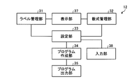
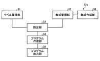
- FIG. 2 is a functional block diagram of the program creation device 12 according to the first embodiment.
- the program creation device 12 includes a label management unit 31, a mathematical expression management unit 32, a setting unit 33, a program creation unit 34, and a program output unit 35.
- the program creation device 12 further includes a display unit 37 and an input unit 38.
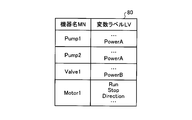
- the label management unit 31 manages input / output variables of a control program executed by the control device 13 that controls the device 14 to control the device 14 in association with variable labels. More specifically, the label management unit 31 combines the name of the device 14 and a list of variable labels corresponding to the input / output variables of the control program according to the configuration of the device 14 constituting the factory or various infrastructure facilities. Create an I / O label list.
- the input / output variables vary depending on the type of the device 14, but when the device 14 is a pump, driving horsepower, power consumption, and discharge amount are exemplified.
- the valve opening command and the valve opening are For example, when the device 14 is a fan, a rotation speed command is illustrated, and when the device 14 is an electric motor, a torque command and a rotation speed command are illustrated.
- the input / output variables are not limited to these.
- the label management unit 31 causes the display unit 37 to display the created input / output label list.
- the input / output variables of the control program include both variables given to the control program and variables output from the control program by calculation or calculation by the control program.
- the variable label is a character string attached to the data item of the input / output variable in order to distinguish the input / output variable.
- the mathematical expression management unit 32 manages mathematical expression frames constituting mathematical expressions used in the calculation program executed by the control device 13. More specifically, the formula management unit 32 causes the display unit 37 to display a list of formulas including a plurality of formulas. Formulas included in the list of formulas are used when the control device 13 performs calculation processing on input / output variables of the control program executed by the control device 13.
- the mathematical formula includes a mathematical formula frame.
- the mathematical expression frame is a mathematical expression described using operators, function names, and variables used in the calculation.
- the formula list is referred to as a formula frame list as appropriate.
- the setting unit 33 selects a variable label and a mathematical expression based on a command input via the input unit 38.
- the input unit 38 is a device for inputting commands and data to the program creation device 12.
- the program creation unit 34 creates a calculation program executed by the control device 13 based on the variable label and the selection information of the mathematical formula. Specifically, the program creation unit 34 selects a formula managed by the formula management unit 32, selects a variable label to be used in the selected formula from the variable labels managed by the label management unit 31, and selects the selected formula and variable label. Create a calculation program based on The program creation unit 34 creates a control program that is executed when the control device 13 controls the device 14.
- the selection information is information indicating which variable label and mathematical expression the user of the program creation device 12 has selected from a plurality of variable labels and a plurality of mathematical expressions.
- selection information is generated.
- the program output unit 35 outputs the created calculation program to the control program of the control device 13. Specifically, the program output unit 35 stores the created calculation program in the storage unit of the program creation device 12 as a part of the control program of the control device 13.
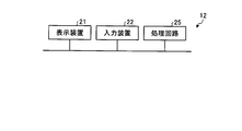
- the program creation device 12 includes a display device 21 that is a display unit 37, an input device 22 that is an input unit 38, a processor 23, and a memory 24.
- the display device 21 is a device that displays information, and is exemplified by a liquid crystal display, but is not limited thereto.
- the input device 22 is a device that inputs commands and data to the program creation device 12. Examples include, but are not limited to, a keyboard, a mouse, a pointing device, and a touch panel.
- the functions of the label management unit 31, the mathematical expression management unit 32, the setting unit 33, the program creation unit 34, and the program output unit 35 of the program creation device 12 are realized by the processor 23.
- the processor 23 is also referred to as a CPU (Central Processing Unit), a processing device, an arithmetic device, a microprocessor, a microcomputer, or a DSP (Digital Signal Processor).
- the functions of the label management unit 31, the mathematical expression management unit 32, the setting unit 33, the program creation unit 34, and the program output unit 35 are realized by software, firmware, or a combination of software and firmware.
- Software and firmware are described as programs and stored in the memory 24.
- the processor 23 reads out and executes the program stored in the memory 24, thereby realizing the functions of the label management unit 31, the mathematical expression management unit 32, the setting unit 33, the program creation unit 34, and the program output unit 35.
- These programs cause the computer to execute the procedure executed by the label management unit 31, the mathematical expression management unit 32, the setting unit 33, the program creation unit 34, and the program output unit 35 and the program creation method according to the first embodiment. It can be said.
- the memory 24 is a volatile or non-volatile semiconductor memory such as RAM (Random Access Memory), ROM (Read Only Memory), flash memory, EPROM (Erasable Programmable Read Only Memory), and EEPROM (Electrically Erasable Programmable Read Only Memory), Magnetic disks, flexible disks, optical disks, compact disks, mini disks, and DVDs (Digital Versatile Discs) are applicable.
- RAM Random Access Memory
- ROM Read Only Memory
- flash memory EPROM (Erasable Programmable Read Only Memory), and EEPROM (Electrically Erasable Programmable Read Only Memory), Magnetic disks, flexible disks, optical disks, compact disks, mini disks, and DVDs (Digital Versatile Discs) are applicable.
- the memory 24 includes a volatile storage device 24V such as a RAM and a nonvolatile storage device 24UV such as a ROM.
- the nonvolatile storage device 24UV is used when creating a program for realizing the functions of the label management unit 31, the mathematical formula management unit 32, the setting unit 33, the program creation unit 34, and the program output unit 35, and a control program and a calculation program. Setting data to be stored.
- a volatile storage device 24V is appropriately used as a work memory when the processor 23 executes processing.
- the functions of the label management unit 31, the mathematical expression management unit 32, the setting unit 33, the program creation unit 34, and the program output unit 35 of the program creation device 12 may be realized by a processing circuit 25 that is dedicated hardware.
- the processing circuit 25 corresponds to a single circuit, a composite circuit, a programmed processor, a parallel programmed processor, an ASIC (Application Specific Integrated Circuit), an FPGA (Field Programmable Gate Array), or a combination thereof. To do.
- Different processing circuits 25 may realize the functions of the label management unit 31, the mathematical expression management unit 32, the setting unit 33, the program creation unit 34, and the program output unit 35, or the functions may be combined into one processing circuit. 25 may be realized.
- Each function of the label management unit 31, the mathematical expression management unit 32, the setting unit 33, the program creation unit 34, and the program output unit 35 is partially realized by dedicated hardware, and partly realized by software or firmware. Good.
- the program creation device 12 realizes the functions of the label management unit 31, the formula management unit 32, the setting unit 33, the program creation unit 34, and the program output unit 35 by hardware, software, firmware, or a combination thereof. can do.
- the hardware configuration of the monitoring control device 11 is the same as that of the program creation device 12.
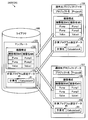
- FIG. 5 is a diagram showing the library 41 stored in the memory 24 of the program creation device 12 according to the first embodiment.
- 6 and 7 are diagrams illustrating an example of a screen displayed on the display device 21 by the program creation device 12 according to the first embodiment.
- FIG. 8 is a diagram showing a calculation program 48 and a calculation result label 49 created by the program creation device 12 according to the first embodiment.
- the library 41 stored in the nonvolatile storage device 24UV of the memory 24 includes a control program 42 and an input / output label list 43.
- the control program 42 is a program executed when the control device 13 shown in FIG.
- the input / output label list 43 is a list of variable labels LV corresponding to the input / output variables of the control program 42.
- the variable label LV is a character string such as Status or Power included in the input / output label list 43.
- the input / output variable represented by% 1 is the operating state of the device 14, and the input / output variable represented by% 2 represents the power consumption of the device 14.
- the input / output label list 43 stores variable labels LV and input / output variables in association with each other.
- the input / output label list 43 includes one or more variable labels and input / output variables.
- the library 41 includes control programs 42P and 42V for controlling the plurality of devices 14 and input / output label lists 43P and 43V for the plurality of devices 14.
- the library 41 includes a pump control program 42 ⁇ / b> P and a valve control program 42 ⁇ / b> V. When these are not distinguished, they are referred to as a control program 42.
- the control program 42 is prepared for each device 14. Devices 14 of the same type are controlled by the same control program 42.
- the control program 42 is versatile for the same type of device 14.
- the control program 42 is appropriately referred to as a general-purpose control program 42.
- the library 41 includes an input / output label list 43 ⁇ / b> P of a pump and an input / output label list 43 ⁇ / b> V of a valve (Valve). When these are not distinguished, they are referred to as an input / output label list 43.
- the input / output label list 43 is prepared for each device 14. The same input / output label list 43 is applied to the devices 14 of the same type. As described above, the input / output label list 43 is versatile for the same type of device 14.
- the input / output label list 43 is appropriately referred to as a general-purpose input / output label list 43.
- the processor 23 of the program creation device 12 causes the display device 21 to display a device configuration setting screen 21MS shown in FIG.
- the user operates the input device 22 in a state in which the device configuration setting screen 21MS is displayed on the display device 21, and inputs the device type MS and the device name MN in an inputable area of the device configuration setting screen 21MS.
- Configuration 44 is set.
- the device configuration 44 is a list of devices 14 included in the control system 1 shown in FIG. 1, and is represented by a combination of the device type MS and the name of the device 14, that is, the device name MN.
- the device name MN is used to distinguish each device 14 when there are a plurality of devices 14 of the same type.
- the processor 23 temporarily stores the set device configuration 44 in the storage area of the volatile storage device 24V of the memory 24.
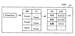
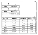
- the processor 23 causes the display device 21 to display the calculation program setting screen 21PS shown in FIG.
- the calculation program setting screen 21PS includes a calculation name 45, a label list 46, and a formula list 47.
- the calculation name 45 is a character string input to the program creation device 12 by the user, and becomes an output data name of the calculation program created by the program creation device 12.
- the label list 46 is a list in which the relationship between the device name MN of the device 14 included in the control system 1 and the variable label LV corresponding to the device name MN is described.
- the label management unit 31 configures a device name MN and a list of variable labels LV corresponding to input / output variables of the general-purpose control program 42 executed by the control device 13 that controls the device 14, that is, a general-purpose input / output label list 43. By combining them according to 44, a label list 46 is created. At this time, the label management unit 31 reads the device configuration 44 from the volatile storage device 24 ⁇ / b> V, and acquires the general-purpose input / output label list 43 of the device type MS corresponding to the device name MN of the device configuration 44 from the library 41. Then, the label management unit 31 combines the acquired general-purpose input / output label list 43 with the corresponding device name MN.
- the label management unit 31 creates the label list 46 by acquiring the general-purpose input / output label list 43 from the library 41 for all the device names MN included in the device configuration 44 and combining them to create a list.
- the label management unit 31 displays the created label list 46 on the display device 21.
- the formula list 47 is a list of formulas used in a calculation program executed by the control device 13.
- the formula list 47 is a list in which the formula name EN and the formula EXP are associated with each other.
- the mathematical expression list 47 is stored in the nonvolatile storage device 24UV of the memory 24.
- the expression EXP may be an expression frame, that is, an expression including an operator, a function name, and variables used in the calculation.
- the expression EXP may be one in which arithmetic calculation is described, or one in which logical calculation is described.
- the user selects the formula EXP included in the formula list 47 displayed on the calculation program setting screen 21PS, and inputs the character string indicating the selected formula EXP to the program creation device 12 via the input device 22.
- the setting unit 33 selects the formula EXP based on a command input via the input device 22, that is, a command for selecting the formula EXP.
- the program creation unit 34 creates a control program PGC. Specifically, the program creation unit 34 reads the general-purpose control program 42 of the device type MS corresponding to the device name MN from the library 41 and associates the device name MN with the above-described device name MN. The program creation unit 34 associates the device name MN with the general-purpose input / output label list 43 corresponding to the device name MN. In this way, the program creation unit 34 can identify the general-purpose control program 42 and the general-purpose input / output label list 43 as the individual control program 42 and the input / output label list 43. Further, the program creation unit 34 creates a calculation program 48 and a calculation result label 49 based on the calculation name 45 and the variable label LV and the selection information of the expression EXP. The calculation result label 49 is a calculation name 45, that is, a character string representing the calculation name 45.
- the program output unit 35 outputs the general-purpose control program 42 and the general-purpose input / output label list 43 associated with the device name MN to the control program PGC.
- the program output unit 35 outputs the calculation program 48 and the calculation result label 49 created by the program creation unit 34 to the control program PGC.
- the program creation device 12 creates a control program PGC for the control device 13 to control the device 14 included in the control system 1.
- the input / output variables of the control program PGC are also input / output variables of the general-purpose control program 42.
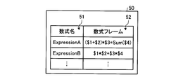
- FIG. 9 is a diagram showing the mathematical expression frame list 50 according to the first embodiment.
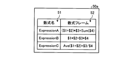
- the formula frame list 50 includes a formula frame 52.
- the formula frame list 50 is a list including a plurality of combinations of formula names 51 and formula frames 52.
- a mathematical expression frame 52 in which a mathematical expression name 51 is expressed by a character string of Expression A has an addition operator + and a multiplication operator * as operators, a total function Sum as a function, and a variable used in calculation. $ 1, $ 2, $ 3, and $ 4.
- a mathematical expression frame 52 in which a mathematical expression name 51 is expressed by a string of Expression B has an addition operator + and a multiplication operator * as operators, and $ 1, $ 2, $ 3 as variables used in the calculation. $ 4.
- the mathematical expression frame 52 is stored in the nonvolatile storage device 24UV of the memory 24 included in the program creation device 12.
- the variables used in the calculation will be referred to as mathematical variables as appropriate in the following.
- the formula frame list 50 may include a formula EXP.
- FIG. 10 is a diagram showing a data configuration of the calculation program setting data 60 according to the first embodiment.
- the calculation program setting data 60 includes calculation name data 61, mathematical formula data 62, and a mathematical formula parameter list 63.
- the calculation name data 61 is information indicating the calculation name 45 input to the program creation device 12 by the user.
- the formula data 62 is information including at least one of the formula EXP and the formula frame 52 selected by the user.
- the formula parameter list 63 is information including formula data 62 and selection information of variables and variable labels LV used in the formula EXP.
- the formula parameter list 63 is configured in a data format that can select a plurality of formula variables for one formula variable, for example, an array, in order to calculate a function having a plurality of inputs.
- a plurality of formula variables for one formula variable for example, an array
- three formula variables $ 4, $ 4 [0], $ 4 [1], and $ 4 [2] are set.
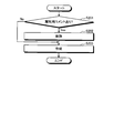
- FIG. 11 is a flowchart showing an example of processing in which the program creation device 12 according to the first embodiment creates a control program.
- This process is a program creation method according to the first embodiment.
- the processor 23 of the program creation device 12 causes the display device 21 to display a device configuration setting screen 21MS shown in FIG.
- the user operates the input device 22 in a state where the device configuration setting screen 21MS is displayed on the display device 21, and inputs the device type MS and the device name MN in the inputable area of the device configuration setting screen 21MS.
- 6 is input to the program creation device 12 to set the device configuration 44 shown in FIG.
- the processor 23 of the program creation device 12 receives this input, and temporarily stores the set device configuration 44 in the storage area of the volatile storage device 24V of the memory 24.
- step S102 the processor 23 causes the display device 21 to display the calculation program setting screen 21PS shown in FIG.
- the user inputs a character string that becomes the output data name of the calculation program to the calculation name 45 of the calculation program setting screen 21PS by the input device 22.
- the mathematical expression management unit 32 sets the input character string in the calculation name 45 of the calculation name data 61 of the calculation program setting data 60 shown in FIG.
- step S103 the mathematical formula management unit 32 displays the mathematical formula frame list 50 stored in the nonvolatile storage device 24UV of the memory 24 on the calculation program setting screen 21PS.
- the formula management unit 32 may also display the formula list 47 on the calculation program setting screen 21PS.
- the user selects at least one of the formula frame 52 and the formula EXP calculated by the calculation program 48 from the formula frame list 50.
- the formula list 47 is displayed on the calculation program setting screen 21PS, the user may select the formula EXP calculated by the calculation program 48 from the formula list 47, or by combining the selected formulas with the formula frame. 52 may be created.
- step S104 the setting unit 33 adds at least one of the selected formula frame 52 and the formula EXP to the formula data 62 of the calculation program setting data 60 and its formula. Name 51 is set.
- the setting unit 33 sets the selected formula EXP and its formula name EN in the formula data 62 of the calculation program setting data 60.
- step S105 the label management unit 31 combines the device name MN and the general-purpose input / output label list 43 corresponding to the input / output variables of the general-purpose control program 42 in accordance with the set device configuration 44, thereby providing a label list. 46 is created and displayed on the calculation program setting screen 21PS.
- Step S105 may be between step S101 and step S102.
- step S106 the setting unit 33 sets the selected variable label LV in the formula parameter list 63 in association with the formula variable.
- the program creation unit 34 specifies the device name MN for the general-purpose control program 42 and the general-purpose input / output label list 43 stored in the library 41 according to the device configuration 44, or specifies the device name MN. Given a unique name based on.
- step S108 the program creation unit 34 creates a calculation program 48 based on the mathematical expression parameter list 63 of the calculation program setting data 60.
- the calculation program 48 receives the specified variable label LV, that is, the variable label LV given the device name MN, and outputs the calculation result label 49 of the character string of the calculation name 45 set in the calculation name data 61. It is a program.
- a calculation program 48 is obtained by assigning the variable label LV associated with the mathematical expression parameter list 63 to the mathematical expression variable of the mathematical expression frame 52 and the mathematical expression EXP set in the mathematical expression data 62.
- the control device 13 executes the calculation program 48, the formula frame 52 and the formula EXP set in the formula data 62 are calculated using the variable label LV given the device name MN as the formula variable. This calculation result is associated with the calculation result label 49.
- step S109 the program output unit 35 sends the general-purpose control program 42, the general-purpose input / output label list 43, the created calculation program 48, and the created calculation result label 49 associated with the device name MN to the control program PGC. Output.
- the program creation device 12 creates the control program PGC.
- the program creation device 12 stores at least one of the formula frame 52 and the formula EXP used for the calculation program 48 and the variable label LV in the memory 24, and at least the formula frame 52 and the formula EXP used by the calculation program 48.
- One and the variable label LV are selected by the user.
- the program creation device 12 creates the calculation program 48 based on the selection information of at least one of the formula frame 52 and the formula EXP, the variable label LV, and the configuration of the device 14 of the control system 1. That is, the program creation device 12 causes the user to select the formula frame 52 and the formula EXP stored in the memory 24 in advance and the variable label LV to be a formula variable, and creates the calculation program 48 based on the selection result.
- the program creation device 12 can suppress the man-hours for creating the program executed by the control device 13, and can suppress a mistake in the program due to a user input error.
- the formula frame 52 and the formula EXP are elements constituting the calculation program 48, and formula variables can be set according to the configuration of the device 14 of the control system 1. Since the program creation device 12 stores a plurality of mathematical expression frames 52 and mathematical expressions EXP in the memory 24, it can correspond to various calculation programs 48. For this reason, the program creation apparatus 12 can respond to the configuration of various devices 14 and is highly versatile. Unlike the C language, it is difficult to easily create the calculation program 48 for the ladder program used in the PLC, but the program creation device 12 can easily create the calculation program 48 in the ladder program and make mistakes. Can be suppressed.
- FIG. FIG. 12 is a functional block diagram of the program creation device 12a according to the second embodiment.
- FIG. 13 is a diagram showing the mathematical expression frame list 50a according to the second embodiment.
- the program creation device 12a includes a formula creation unit 36 in addition to the program creation device 12 of the first embodiment. Other configurations are the same as those in the first embodiment.
- the hardware configuration of the program creation device 12a is the same as that of the program creation device 12 of the first embodiment.
- the formula generator 36 is realized by the processor 23 and the memory 24 shown in FIG. 3 or the processing circuit 25 shown in FIG.
- the formula creation unit 36 creates or edits the formula frame 52 according to the input, more specifically, the user's input.
- the formula creating unit 36 may create or edit the formula EXP.
- the formula management unit 32 adds the formula frame 52 or the formula EXP created or edited by the formula creation unit 36 to the formula frame list 50a.
- a formula frame 52 having a formula name 51 represented by a character string ExpressionC is added to the formula frame list 50a.
- the formula frame 52 or the formula EXP held in the formula frame list 50a is edited using the input device 22 shown in FIG. 3 or FIG.
- the formula frame 52 or the formula EXP is created.
- the formula creating unit 36 edits the formula frame 52 or the formula EXP according to the acquired command, or creates a new formula frame 52 or Or create an expression EXP.
- the formula management unit 32 writes the formula frame 52 or the formula EXP that has been edited to the formula frame list 50a, or writes the newly created formula frame 52 formula EXP to the formula frame list 50a.
- the formula creation unit 36 displays the formula frame 52 or the formula EXP to be edited on the screen of the display device 21. In this way, the user can easily edit the formula frame 52 or the formula EXP.
- the formula management unit 32 includes the formula frame 52 and the formula EXP defined by the user as candidates for the formula frame 52 and the formula EXP used in the calculation program 48 on the calculation program setting screen 21PS.
- the list 50a can be displayed.
- the setting unit 33 can set this in the formula data 62.
- the program creation unit 34 can create a calculation program 48 using the mathematical expression frame 52 and the mathematical expression EXP defined by the user. As a result, the program creation device 12a can create the calculation program 48 for performing the calculation set by the user.
- the label management unit 31 of the above-described program creation devices 12 and 12a filters and displays a plurality of variable labels LV on the display device 21 and sorts and displays them on the display device 21. Do at least one. For filtering and sorting the variable label LV, at least one of the device name MN, the name of the variable label LV, and the device type MS is used.
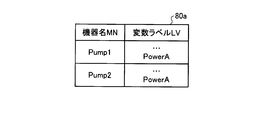
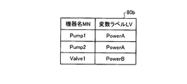
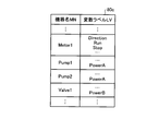
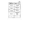
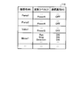
- FIG. 14 is a diagram showing a label list 80 according to the third embodiment.
- 15 and 16 are diagrams showing label lists 80a and 80b obtained by filtering the label list 80 according to the third embodiment.
- 17 and 18 are diagrams showing label lists 80c and 80d obtained by sorting the label list 80 according to the third embodiment. Next, examples of filtering and sorting will be described.
- the label management unit 31 filters the label list 80 shown in FIG. 14 with the device type MS Pump, thereby extracting the variable label LV with the device type MS Pump, and the label list 80a shown in FIG. create.
- the label management unit 31 causes the display device 21 to display the created label list 80a when the user selects the variable label LV.
- the device type MS is a character string portion excluding the number of the device name MN.
- the label management unit 31 extracts the variable label LV including “Power” in the name by filtering the label list 80 illustrated in FIG. 14 with the name of the variable label LV including “Power”, and is illustrated in FIG.
- a label list 80b is created.
- the label management unit 31 displays the created label list 80b on the display device 21 when the user selects the variable label LV.
- the label management unit 31 creates the label list 80c shown in FIG. 17 by sorting the label list 80 shown in FIG. 14 in ascending order of the first character of the character string indicating the device name MN.
- the label management unit 31 causes the display device 21 to display the created label list 80c when the user selects the variable label LV.
- the label management unit 31 creates the label list 80d shown in FIG. 18 by sorting the label list 80 shown in FIG. 14 in descending order of the first character of the character string indicating the device name MN.
- the label management unit 31 causes the display device 21 to display the created label list 80d when the user selects the variable label LV.
- the label management unit 31 can narrow down the items in the label list 80 and change the arrangement. As a result, the label management unit 31 can change the label list 80 into a form that is easy for the user to select, so that it is possible to improve convenience when the user selects the variable label LV, and the variable label LV. The selection error can be reduced.
- FIG. 19 is a diagram showing control programs PGCb and PGCa according to the fourth embodiment.
- the control programs 91b and 91a, the calculation programs 98b and 98a, and the label lists 92b and 92a included in the control programs PGCb and PGCa created by the program creation unit 34 of the program creation devices 12 and 12a described above include Comment CM can be added.
- the comment CM also includes an identifier indicating that it has been created by the program creation unit 34. Therefore, the control program 91b, 91a, the calculation program 98b, 98a, and the label list 92b, 92a can be given an identifier indicating that the program has been created by the program creation unit 34.
- this identifier is referred to as an identification comment as appropriate.
- the identification comment is shown in FIG. ! ].
- the program output unit 35 uses an identification comment [! ! ],
- the control programs 91b and 91a created by the program creation unit 34 can be distinguished from the user program 95 which is a control program created by the user.
- the calculation programs 98b and 98a and the label lists 92b and 92a are distinguished from a user calculation program which is a calculation program created by the user and a user label list 92i which is a label list created by the user.
- the program output unit 35 of the program creation devices 12 and 12a uses the identification comment [! ! ] Is deleted from the control program PGCb, the control program 91b, the calculation program 98b, and the label list 92b.
- the user program 95 and the user label list 92i remain in the control program PGCi after deletion. If the user calculation program is included in the control program PGCb, the user calculation program remains in the deleted control program PGCi.
- the program output unit 35 outputs the new control program 91a, the calculation program 98a, and the label list 92a created by the program creation unit 34 to the control program PGCi in which the user program 95 and the user label list 92i remain. In this way, the program creation devices 12 and 12a create a new control program PGCa.
- FIG. 20 is a flowchart showing a procedure of processing executed by the program creation devices 12 and 12a in the fourth embodiment.
- the program output unit 35 adds an identification comment [! To the already created control program PGCb. ! ] (Yes in step S201), an identification comment [! ! ] Is deleted from the control program PGCb, the control program 91b, the calculation program 98b, and the label list 92b.
- the program output unit 35 creates a new control program PGCa using the deleted control program PGCi.
- the program output unit 35 adds an identification comment [!] To the already created control program PGCb. !
- step S201 a new control program 91a, a calculation program 98a and a label list 92a created by the program creation unit 34 are output to the control program PGCb already created in step S203, A new control program PGCa is created. In this way, the program creation devices 12 and 12a create a new control program PGCa.
- the program creation devices 12 and 12a can create a new control program PGCa by using the already created control program PGCb.
- the program creation devices 12 and 12a delete the existing calculation program 98b and the control program 91b to make a new calculation program 98b and a control program 98b. For this reason, the program creation devices 12 and 12a can easily change the existing calculation program 98b and the control program 91b.
- FIG. FIG. 21 is a block diagram showing the application source project data 104, the application destination project data 107, and the library 100 stored in the nonvolatile storage device 24UV according to the fifth embodiment.
- the program creation devices 12 and 12a store the template 101 in which the variable label LV used for generating the calculation program 48, the mathematical expression frame 52, and the configuration of the device 14 are associated.
- the storage unit is a memory 24, and more specifically, a nonvolatile storage device 24UV.
- the formula frame 52 of the template 101 may be a formula EXP.
- the user creates all the data required by the program creation devices 12 and 12a as the application project data 104 in order to create the control program PGC.
- the application source project data 104 is stored in the nonvolatile storage device 24UV of the memory 24.
- the setting unit 33 stores the device configuration 105 and the calculation program setting data 106 input to the application source project data 104 as the template 101 of the library 100.
- the template 101 includes a device configuration 102 and calculation program setting data 103.
- the created template 101 is written into the library 100 stored in the nonvolatile storage device 24UV of the memory 24.
- the device configurations 105 and 102 are combinations of the device type MS and the device name MN, and are the same as the device configuration 44 described in the first embodiment.
- the calculation program setting data 106 and 103 have the same configuration as the calculation program setting data 60 described in the first embodiment.
- the setting unit 33 compares the application project data 107 with the template 101. As a result of the comparison, when the device configuration 102 of the template 101 and the device configuration 108 of the application project data 107 are the same, the setting unit 33 converts the calculation program setting data 103 of the template 101 into the calculation program setting data 109 of the application project data 107. Read from the library 100. Then, the setting unit 33 sets the read calculation program setting data 103 of the template 101 in the calculation program setting data 109 of the application project data 107.
- the information regarding the setting of the calculation program 48 once input to the program creation devices 12 and 12a, more specifically, the calculation program setting data 103 can be reused.
- the input effort is reduced.
- the configuration disclosed in the fifth embodiment can be appropriately applied to the following embodiments.
- FIG. 22 is a diagram showing a label list 110 according to the sixth embodiment.
- the label list 110 is obtained by adding a communication attribute BG to the label list 46 according to the first to fifth embodiments.
- the communication attribute BG is information indicating whether or not to transmit the variable label LV used in the calculation program 48 created by the program creation unit 34 to the monitoring control device 11.
- the communication attribute BG is added to the label list 46, and the label management unit 31 assigns the communication attribute BG to the variable label LV, so that the monitoring control device 11 transmits and receives the variable label LV. Allow setting whether or not.
- the program creation devices 12 and 12 a transmit the variable label LV to the monitoring control device 11.
- the program creation devices 12 and 12a do not transmit the variable label LV to the monitoring control device 11.
- transmission / reception of unnecessary information can be reduced by the communication attribute BG, the performance of data communication between the control device 13 and the monitoring control device 11 can be improved.
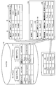
- FIG. 23 is a diagram showing the mathematical expression frame list 123 and the calculation program setting data 126 according to the seventh embodiment.
- the formula frame list 123 according to the seventh embodiment includes a parameter selection condition CDC that is information for selecting the variable label LV used in the formula frame 52 and the formula EXP in the formula frame list 50 according to the first embodiment. It is added. That is, the formula frame list 123 includes the parameter selection condition CDC. Specifically, the formula frame list 123 is a list including combinations of the formula name 51, the formula frame 52, and the parameter selection condition CDC. The formula frame 52 in the formula frame list 123 may be a formula EXP.
- the mathematical expression frame list 123 is stored in the nonvolatile storage device 24UV of the memory 24 that is a storage unit.
- the parameter selection condition CDC includes names of comment CM, variable label LV, and variable label LV, but is not limited thereto.
- the label list 121 stored in the library 120 is obtained by adding a comment CM to the input / output label list 43 according to the first embodiment.
- a comment CM can be attached to the variable label LV.
- the setting unit 33 When the formula frame 52 or the formula EXP is selected by the user from the formula frame list 123, the setting unit 33 adds the selected formula frame 52 or formula EXP and its formula name 51 to the formula data 124 of the calculation program setting data 126. Set. Next, the setting unit 33 uses the parameter selection condition CDC corresponding to the selected formula frame 52 or the formula EXP and the formula name 51 to set the variables in the label list 121 stored in the library 120 based on the device configuration 122. A keyword search is performed on at least one of the name of the label LV and the comment CM. Then, the setting unit 33 selects the variable label LV corresponding to the keyword from the label list 121 and sets it in the formula parameter list 125 as a formula variable used in the formula frame 52 or the formula EXP.
- the parameter selection condition CDC associated with the formula frame 52 is “comment”. “Comment” is an item to be searched for keywords.
- the setting unit 33 acquires “comment”, which is the parameter selection condition CDC corresponding to the selected formula frame 52 in which the formula name 51 is represented by the character string ExpA, from the formula frame list 123.
- the setting unit 33 searches the comment CM in the label list 121 of the device type MS corresponding to the device name MN with reference to the device configuration 122.
- the device name MN is Pump1
- the setting unit 33 performs a keyword search for the comment CM in the pump (Pump) label list 121.
- the keyword used for the keyword search includes the formula name 51 and the operator, function name, and formula variable included in the formula frame 52 or the formula EXP.
- the setting unit 33 can select the variable label LV represented by the character string Power. .
- the keyword is the formula name 51 in the formula frame list 123.
- the setting unit 33 sets the variable label LV represented by the character string Power selected by the search to the variable label LV of the mathematical expression parameter list 125 as a mathematical variable corresponding to the device name MN represented by the character string Pump1.
- the parameter selection condition CDC associated with the formula frame 52 is “variable label”.
- the setting unit 33 acquires “variable label”, which is the parameter selection condition CDC corresponding to the selected formula frame 52 in which the formula name 51 is represented by the character string ExpB, from the formula frame list 123.
- the setting unit 33 refers to the device configuration 122 and performs a keyword search for the variable label LV of the label list 121 of the device type MS corresponding to the device name MN.
- the device name MN is Pump1
- the setting unit 33 performs a keyword search for the variable label LV of the pump label list 121.
- the keyword used for the keyword search includes the formula name 51 and the operator, function name, and formula variable included in the formula frame 52 or the formula EXP.
- the setting unit 33 may select the variable label LV represented by the character string ExpB_Param1. it can.
- the setting unit 33 sets the variable label LV represented by the character string Power selected by the search as the variable label LV of the formula parameter list 125 as the formula variable used in the formula frame 52 corresponding to the character string Exp.
- the setting unit 33 sets the variable label LV selected by performing a keyword search for the item in the label list 121 corresponding to the parameter selection condition CDC to the mathematical expression frame 52 set in the mathematical expression data 124 of the calculation program setting data 126 or It is set as a formula variable used in the formula EXP.
- the user of the program creation devices 12 and 12a can create the calculation program 48 only by selecting the formula frame 52 or the formula EXP.
- the configuration described in the above embodiment shows an example of the contents of the present invention, and can be combined with another known technique, and can be combined with other configurations without departing from the gist of the present invention. It is also possible to omit or change the part.
Landscapes
- Physics & Mathematics (AREA)
- General Physics & Mathematics (AREA)
- Engineering & Computer Science (AREA)
- Automation & Control Theory (AREA)
- Programmable Controllers (AREA)
Abstract
Le but de la présente invention est de réduire les heures de travail pour générer un programme devant être exécuté par un dispositif de commande. Le dispositif de génération de programme (12) comprend une unité de gestion d'étiquette (31), une unité de gestion d'expression numérique (32), et une unité de génération de programme (34). L'unité de gestion d'étiquettes (31) gère des variables d'entrée/sortie d'un programme de commande, qui est exécuté par un dispositif de commande pour commander des dispositifs, en association avec des étiquettes variables. L'unité de gestion d'expression numérique (32) gère des expressions numériques utilisées par un programme de calcul devant être exécuté par le dispositif de commande. L'unité de génération de programme (34) sélectionne des expressions numériques devant être gérées par l'unité de gestion d'expression numérique, sélectionne des étiquettes variables devant être utilisées par les expressions numériques sélectionnées parmi les étiquettes variables gérées par l'unité de gestion d'étiquettes, et génère le programme de calcul sur la base des expressions numériques sélectionnées et des étiquettes variables.
Priority Applications (2)
| Application Number | Priority Date | Filing Date | Title |
|---|---|---|---|
| PCT/JP2016/060123 WO2017168564A1 (fr) | 2016-03-29 | 2016-03-29 | Dispositif de génération de programmes, procédé de génération de programmes, et programme |
| JP2016564291A JP6081041B1 (ja) | 2016-03-29 | 2016-03-29 | プログラム作成装置、プログラム作成方法及びプログラム |
Applications Claiming Priority (1)
| Application Number | Priority Date | Filing Date | Title |
|---|---|---|---|
| PCT/JP2016/060123 WO2017168564A1 (fr) | 2016-03-29 | 2016-03-29 | Dispositif de génération de programmes, procédé de génération de programmes, et programme |
Publications (1)
| Publication Number | Publication Date |
|---|---|
| WO2017168564A1 true WO2017168564A1 (fr) | 2017-10-05 |
Family
ID=58043275
Family Applications (1)
| Application Number | Title | Priority Date | Filing Date |
|---|---|---|---|
| PCT/JP2016/060123 Ceased WO2017168564A1 (fr) | 2016-03-29 | 2016-03-29 | Dispositif de génération de programmes, procédé de génération de programmes, et programme |
Country Status (2)
| Country | Link |
|---|---|
| JP (1) | JP6081041B1 (fr) |
| WO (1) | WO2017168564A1 (fr) |
Cited By (1)
| Publication number | Priority date | Publication date | Assignee | Title |
|---|---|---|---|---|
| JP6779418B1 (ja) * | 2020-01-20 | 2020-11-04 | 三菱電機株式会社 | 設計支援装置、設計支援方法および設計支援プログラム |
Citations (6)
| Publication number | Priority date | Publication date | Assignee | Title |
|---|---|---|---|---|
| JPH10260709A (ja) * | 1997-03-18 | 1998-09-29 | Takaoka Electric Mfg Co Ltd | プログラマブルコントローラのプログラミング装置 |
| JP2001022434A (ja) * | 1999-07-09 | 2001-01-26 | Fujitsu Ten Ltd | 負荷の制御状態表示装置 |
| JP2002140105A (ja) * | 2000-10-31 | 2002-05-17 | Yaskawa Electric Corp | プログラマブルコントローラのプログラミング装置 |
| JP2003029806A (ja) * | 2001-07-17 | 2003-01-31 | Yokogawa Electric Corp | 入出力装置及び入出力装置を持つプロセス制御システム |
| JP2013143096A (ja) * | 2012-01-12 | 2013-07-22 | Yokogawa Electric Corp | ラダープログラム作成装置 |
| WO2015170408A1 (fr) * | 2014-05-09 | 2015-11-12 | 三菱電機株式会社 | Système de commande de surveillance, terminal de surveillance, et programme de surveillance |
-
2016
- 2016-03-29 WO PCT/JP2016/060123 patent/WO2017168564A1/fr not_active Ceased
- 2016-03-29 JP JP2016564291A patent/JP6081041B1/ja not_active Expired - Fee Related
Patent Citations (6)
| Publication number | Priority date | Publication date | Assignee | Title |
|---|---|---|---|---|
| JPH10260709A (ja) * | 1997-03-18 | 1998-09-29 | Takaoka Electric Mfg Co Ltd | プログラマブルコントローラのプログラミング装置 |
| JP2001022434A (ja) * | 1999-07-09 | 2001-01-26 | Fujitsu Ten Ltd | 負荷の制御状態表示装置 |
| JP2002140105A (ja) * | 2000-10-31 | 2002-05-17 | Yaskawa Electric Corp | プログラマブルコントローラのプログラミング装置 |
| JP2003029806A (ja) * | 2001-07-17 | 2003-01-31 | Yokogawa Electric Corp | 入出力装置及び入出力装置を持つプロセス制御システム |
| JP2013143096A (ja) * | 2012-01-12 | 2013-07-22 | Yokogawa Electric Corp | ラダープログラム作成装置 |
| WO2015170408A1 (fr) * | 2014-05-09 | 2015-11-12 | 三菱電機株式会社 | Système de commande de surveillance, terminal de surveillance, et programme de surveillance |
Cited By (4)
| Publication number | Priority date | Publication date | Assignee | Title |
|---|---|---|---|---|
| JP6779418B1 (ja) * | 2020-01-20 | 2020-11-04 | 三菱電機株式会社 | 設計支援装置、設計支援方法および設計支援プログラム |
| WO2021149116A1 (fr) * | 2020-01-20 | 2021-07-29 | 三菱電機株式会社 | Dispositif d'aide à la conception, procédé d'aide à la conception, et programme d'aide à la conception |
| CN114981743A (zh) * | 2020-01-20 | 2022-08-30 | 三菱电机株式会社 | 设计辅助装置、设计辅助方法及设计辅助程序 |
| CN114981743B (zh) * | 2020-01-20 | 2023-09-29 | 三菱电机株式会社 | 设计辅助装置、设计辅助方法及计算机可读取的存储介质 |
Also Published As
| Publication number | Publication date |
|---|---|
| JP6081041B1 (ja) | 2017-02-15 |
| JPWO2017168564A1 (ja) | 2018-04-05 |
Similar Documents
| Publication | Publication Date | Title |
|---|---|---|
| JP5850033B2 (ja) | フィールド機器管理装置、機器情報表示方法、コンピュータプログラムおよび記録媒体 | |
| JP4462449B2 (ja) | 制御システム設定装置 | |
| TWI464558B (zh) | 程式作成支援裝置 | |
| CN105573236B (zh) | 信息处理装置、信息处理方法及记录介质 | |
| CN103384858B (zh) | 工程设计装置 | |
| JP5619328B1 (ja) | シーケンスプログラム作成支援装置 | |
| CN105144004B (zh) | 程序图显示装置以及程序图显示方法 | |
| US12169801B2 (en) | Flexible work breakdown structure | |
| CN107408001A (zh) | 数据编辑装置、数据编辑方法以及数据编辑程序 | |
| US20120185065A1 (en) | Device information display apparatus, storage device storing device information display program, and device information display method | |
| JP6904994B2 (ja) | 画面作成装置及び画面作成システム | |
| JP6081041B1 (ja) | プログラム作成装置、プログラム作成方法及びプログラム | |
| CN113885937A (zh) | 一种基于通用性的rpa元素修复方法 | |
| JPWO2017179177A1 (ja) | 情報管理装置、情報管理方法および情報管理システム | |
| US7613593B2 (en) | Methods for configuring an electrical system | |
| JP6337810B2 (ja) | 情報処理装置、情報処理方法、およびプログラム | |
| CN105122157B (zh) | 程序编辑装置以及程序编辑方法 | |
| CN110447028B (zh) | 系统设计辅助装置及系统设计辅助方法 | |
| CN105408826A (zh) | 系统构建辅助装置、方法以及记录介质 | |
| CN107003649B (zh) | 系统设计辅助工具 | |
| JP7204054B1 (ja) | プログラム、設定装置及び表示方法 | |
| KR101718086B1 (ko) | Hmi의 태그 처리 장치 및 방법 | |
| JP2016042386A (ja) | フィールド機器管理装置、機器情報表示方法、コンピュータプログラムおよび記録媒体 | |
| JP4001458B2 (ja) | タグ名共有化装置、タグ名共有化方法およびその方法をコンピュータに実行させるプログラムを記録したコンピュータ読み取り可能な記録媒体 | |
| US20220027346A1 (en) | Framework for managing tag bundles |
Legal Events
| Date | Code | Title | Description |
|---|---|---|---|
| ENP | Entry into the national phase |
Ref document number: 2016564291 Country of ref document: JP Kind code of ref document: A |
|
| NENP | Non-entry into the national phase |
Ref country code: DE |
|
| 121 | Ep: the epo has been informed by wipo that ep was designated in this application |
Ref document number: 16896784 Country of ref document: EP Kind code of ref document: A1 |
|
| 122 | Ep: pct application non-entry in european phase |
Ref document number: 16896784 Country of ref document: EP Kind code of ref document: A1 |