WO2017168552A1 - 画像伝送システム、画像受信装置、画像送信装置、画像伝送方法、画像受信方法、画像送信方法、およびプログラム - Google Patents
画像伝送システム、画像受信装置、画像送信装置、画像伝送方法、画像受信方法、画像送信方法、およびプログラム Download PDFInfo
- Publication number
- WO2017168552A1 WO2017168552A1 PCT/JP2016/060075 JP2016060075W WO2017168552A1 WO 2017168552 A1 WO2017168552 A1 WO 2017168552A1 JP 2016060075 W JP2016060075 W JP 2016060075W WO 2017168552 A1 WO2017168552 A1 WO 2017168552A1
- Authority
- WO
- WIPO (PCT)
- Prior art keywords
- image
- synchronization signal
- communication data
- display
- data
- Prior art date
- Legal status (The legal status is an assumption and is not a legal conclusion. Google has not performed a legal analysis and makes no representation as to the accuracy of the status listed.)
- Ceased
Links
Images
















Classifications
-
- H—ELECTRICITY
- H04—ELECTRIC COMMUNICATION TECHNIQUE
- H04N—PICTORIAL COMMUNICATION, e.g. TELEVISION
- H04N21/00—Selective content distribution, e.g. interactive television or video on demand [VOD]
- H04N21/20—Servers specifically adapted for the distribution of content, e.g. VOD servers; Operations thereof
- H04N21/23—Processing of content or additional data; Elementary server operations; Server middleware
- H04N21/242—Synchronisation processes, e.g. processing of PCR [Programme Clock References]
-
- H—ELECTRICITY
- H04—ELECTRIC COMMUNICATION TECHNIQUE
- H04N—PICTORIAL COMMUNICATION, e.g. TELEVISION
- H04N5/00—Details of television systems
- H04N5/04—Synchronising
- H04N5/06—Generation of synchronising signals
- H04N5/067—Arrangements or circuits at the transmitter end
- H04N5/073—Arrangements or circuits at the transmitter end for mutually locking plural sources of synchronising signals, e.g. studios or relay stations
-
- H—ELECTRICITY
- H04—ELECTRIC COMMUNICATION TECHNIQUE
- H04N—PICTORIAL COMMUNICATION, e.g. TELEVISION
- H04N21/00—Selective content distribution, e.g. interactive television or video on demand [VOD]
- H04N21/40—Client devices specifically adapted for the reception of or interaction with content, e.g. set-top-box [STB]; Operations thereof
- H04N21/43—Processing of content or additional data, e.g. demultiplexing additional data from a digital video stream; Elementary client operations, e.g. monitoring of home network or synchronising decoder's clock; Client middleware
- H04N21/4302—Content synchronisation processes, e.g. decoder synchronisation
-
- H—ELECTRICITY
- H04—ELECTRIC COMMUNICATION TECHNIQUE
- H04N—PICTORIAL COMMUNICATION, e.g. TELEVISION
- H04N21/00—Selective content distribution, e.g. interactive television or video on demand [VOD]
- H04N21/40—Client devices specifically adapted for the reception of or interaction with content, e.g. set-top-box [STB]; Operations thereof
- H04N21/43—Processing of content or additional data, e.g. demultiplexing additional data from a digital video stream; Elementary client operations, e.g. monitoring of home network or synchronising decoder's clock; Client middleware
- H04N21/436—Interfacing a local distribution network, e.g. communicating with another STB or one or more peripheral devices inside the home
- H04N21/4363—Adapting the video stream to a specific local network, e.g. a Bluetooth® network
- H04N21/43637—Adapting the video stream to a specific local network, e.g. a Bluetooth® network involving a wireless protocol, e.g. Bluetooth®, RF or wireless LAN [IEEE 802.11]
-
- H—ELECTRICITY
- H04—ELECTRIC COMMUNICATION TECHNIQUE
- H04N—PICTORIAL COMMUNICATION, e.g. TELEVISION
- H04N21/00—Selective content distribution, e.g. interactive television or video on demand [VOD]
- H04N21/60—Network structure or processes for video distribution between server and client or between remote clients; Control signalling between clients, server and network components; Transmission of management data between server and client, e.g. sending from server to client commands for recording incoming content stream; Communication details between server and client
- H04N21/63—Control signaling related to video distribution between client, server and network components; Network processes for video distribution between server and clients or between remote clients, e.g. transmitting basic layer and enhancement layers over different transmission paths, setting up a peer-to-peer communication via Internet between remote STB's; Communication protocols; Addressing
- H04N21/633—Control signals issued by server directed to the network components or client
- H04N21/6332—Control signals issued by server directed to the network components or client directed to client
- H04N21/6336—Control signals issued by server directed to the network components or client directed to client directed to decoder
-
- H—ELECTRICITY
- H04—ELECTRIC COMMUNICATION TECHNIQUE
- H04N—PICTORIAL COMMUNICATION, e.g. TELEVISION
- H04N21/00—Selective content distribution, e.g. interactive television or video on demand [VOD]
- H04N21/60—Network structure or processes for video distribution between server and client or between remote clients; Control signalling between clients, server and network components; Transmission of management data between server and client, e.g. sending from server to client commands for recording incoming content stream; Communication details between server and client
- H04N21/63—Control signaling related to video distribution between client, server and network components; Network processes for video distribution between server and clients or between remote clients, e.g. transmitting basic layer and enhancement layers over different transmission paths, setting up a peer-to-peer communication via Internet between remote STB's; Communication protocols; Addressing
- H04N21/637—Control signals issued by the client directed to the server or network components
- H04N21/6377—Control signals issued by the client directed to the server or network components directed to server
- H04N21/6379—Control signals issued by the client directed to the server or network components directed to server directed to encoder, e.g. for requesting a lower encoding rate
-
- H—ELECTRICITY
- H04—ELECTRIC COMMUNICATION TECHNIQUE
- H04N—PICTORIAL COMMUNICATION, e.g. TELEVISION
- H04N21/00—Selective content distribution, e.g. interactive television or video on demand [VOD]
- H04N21/80—Generation or processing of content or additional data by content creator independently of the distribution process; Content per se
- H04N21/85—Assembly of content; Generation of multimedia applications
- H04N21/854—Content authoring
- H04N21/8547—Content authoring involving timestamps for synchronizing content
-
- H—ELECTRICITY
- H04—ELECTRIC COMMUNICATION TECHNIQUE
- H04N—PICTORIAL COMMUNICATION, e.g. TELEVISION
- H04N5/00—Details of television systems
- H04N5/04—Synchronising
-
- H—ELECTRICITY
- H04—ELECTRIC COMMUNICATION TECHNIQUE
- H04N—PICTORIAL COMMUNICATION, e.g. TELEVISION
- H04N5/00—Details of television systems
- H04N5/04—Synchronising
- H04N5/12—Devices in which the synchronising signals are only operative if a phase difference occurs between synchronising and synchronised scanning devices, e.g. flywheel synchronising
-
- H—ELECTRICITY
- H04—ELECTRIC COMMUNICATION TECHNIQUE
- H04W—WIRELESS COMMUNICATION NETWORKS
- H04W56/00—Synchronisation arrangements
Definitions
- the present invention relates to an image transmission system, an image reception device, an image transmission device, an image transmission method, an image reception method, an image transmission method, and a program.
- WiFi registered trademark
- IEEE Institute of Electrical and Electronics Engineers 802.11
- An image transmission system for wirelessly transmitting captured image data to and from has been put into practical use.
- the image transmission device transmits captured image data captured by the imaging unit included in the image transmission device to the image reception device, and the image reception device displays an image according to the transmitted captured image data.
- the image is displayed on a display unit provided in the image receiving apparatus.
- each of the image transmission device and the image reception device generates a synchronization signal such as a vertical synchronization signal based on a reference clock signal generated by a crystal oscillation IC, for example, and generates the generated synchronization signal. Operates according to signal timing. That is, in the image transmission device, an image is captured by the imaging unit in accordance with the timing of the synchronization signal generated in the image transmission device. In the image receiving apparatus, an image corresponding to the transmitted captured image data is displayed on the display unit in accordance with the timing of the synchronization signal generated in the image receiving apparatus.
- the delay in wireless transmission fluctuates due to the influence of radio signal interference, environmental changes between the image transmitting apparatus and the image receiving apparatus performing wireless communication, and the like. That is, in wireless communication, the transmission time when wirelessly transmitting captured image data varies. Therefore, in the image transmission system, the captured image data is not always transmitted at the same timing (cycle) even after the wireless connection between the image transmission device and the image reception device is established. The time until the captured image data transmitted by the camera reaches the image receiving device fluctuates.
- the variation in the arrival time of the captured image data is, for example, when the image transmission apparatus transmits captured image data of successive frames such as a moving image, for each frame corresponding to the captured image data received by the image reception apparatus. This is a factor that disturbs the timing (cycle) of displaying an image. This disorder in the timing (cycle) at which the images of the respective frames are displayed becomes a factor that makes the moving image displayed by the image receiving device feel uncomfortable.
- Patent Document 1 a technique of an image transmission device that performs feedback control so as to suppress fluctuations in arrival time of captured image data has been proposed.
- the image transmission apparatus transmits a captured image data with a vertical synchronization marker added thereto, and the image reception apparatus determines the position of the vertical synchronization marker added to the received captured image data. It is monitored whether it is in the range.
- the image receiving apparatus adjusts the timing so that the position of the vertical synchronization marker is within the predetermined range. The amount of synchronization adjustment for transmitting is transmitted to the image transmission apparatus.
- the position of the vertical synchronization marker monitored by the image reception device is feedback-controlled, and the image transmission device can transmit the captured image data at the same timing. It is thought that it will become. That is, with the technique disclosed in Patent Document 1, it is considered that an image transmission device in which an image transmission device and an image reception device are synchronized can be realized.
- the image transmission apparatus adjusts the timing of transmitting the captured image data even though the arrival time of the captured image data is not long. become.
- Patent Document 1 in an image transmission system that uses wireless communication technology, it is disclosed in Patent Document 1 although there is no need to adjust the timing for transmitting captured image data for sudden changes in arrival time. With the technology that has been adopted, timing adjustment is performed in accordance with sudden fluctuations in arrival time. In other words, the technique disclosed in Patent Document 1 reacts sensitively to fluctuations in arrival time and frequently makes unnecessary timing adjustments. Frequent timing adjustment according to this sudden change in arrival time becomes a factor that increases the processing load in the image transmission system. Further, in an image transmission system in which an image transmission apparatus transmits captured image data of continuous frames (for example, moving images), frequent timing adjustment according to sudden changes in arrival time is provided in the image transmission apparatus. Disturbances in the imaging timing (cycle) in the imaging unit, that is, disturbances of moving images.
- the present invention has been made based on the above problem recognition, and in an image transmission system that wirelessly transmits captured image data between an image transmission device and an image reception device, without performing unnecessary timing adjustment, Provided are an image transmission system, an image reception device, an image transmission device, an image transmission method, an image reception method, an image transmission method, and a program capable of stably displaying captured image data captured by the image transmission device.
- the purpose is to do.
- an image transmission system is an image transmission system having an image transmission device and an image reception device, and the image transmission device includes a communication device, an imaging device, a synchronization signal generation function, One or a plurality of processors, the image reception device includes a communication device, a monitor, a synchronization signal generation function, and one or a plurality of processors, and the synchronization signal generation function of the image transmission device generates an imaging synchronization signal
- the one or more processors of the image transmission device cause the imaging device to perform new imaging every time the imaging synchronization signal is generated, and correspond to captured image data output from the imaging device.
- Communication data is transmitted from the communication device of the image transmission device to the image reception device by radio waves, and the synchronization signal generation function of the image reception device generates a display synchronization signal.
- the one or more processors of the image receiving device generate a display image corresponding to the captured image data from the communication data received by radio waves in the communication device of the image receiving device, and the display synchronization signal is Each time the image is generated, the newly generated display image is displayed on the monitor, and one of the processors of the image transmission device and the image reception device is preliminarily configured with the image transmission device and the image reception device. Specific communication data negotiated between the one communication signal after the one synchronization signal generation function generates the display synchronization signal each time the imaging synchronization signal or the display synchronization signal is generated.
- One of the image transmitting device and the image receiving device is transmitted by radio waves from the machine to the other, the image transmitting device or the image From the time when the imaging synchronization signal or the display synchronization signal is generated, for each of the imaging synchronization signal or the display synchronization signal generated by the synchronization signal generation function of the transmission device, the image transmission device or the image reception device
- the synchronization shift time until the reception time of the specific communication data to the communication device is calculated, and one of the processors of the image transmission device and the image reception device has a plurality of calculated synchronization shift times.
- the specific communication data two specific communication data are extracted from the specific communication data excluding the specific communication data having the maximum synchronization shift time, and the image transmission device and the image are extracted.
- One of the processors with the receiving device generates the imaging synchronization signal or the display synchronization signal of the two extracted specific communication data.
- the imaging synchronization signal generated by the one or the other synchronization signal generation function based on the interval and the difference between the synchronization shift times corresponding to each of the two extracted specific communication data Alternatively, an adjustment value of a period of the display synchronization signal is calculated, and the processor of one of the image transmission device and the image reception device is configured to perform the one imaging synchronization signal or the display synchronization based on the adjustment value.
- a communication packet for adjusting a cycle of a signal or adjusting a cycle of the other imaging synchronization signal or the display synchronization signal is transmitted from the one communication device to the other by radio waves.
- the processor that extracts two pieces of communication data may extract the specific communication data having the minimum synchronization shift time as one of the specific communication data to be extracted.
- the identification among the one or more processors of the image transmission device and the one or more processors of the image reception device is divided by the frame interval in the relationship with the one particular communication data extracted as the other one of the particular communication data to be extracted.
- the specific communication data with the minimum value may be extracted.
- the specific communication data is based on a predetermined standard among communication data corresponding to the captured image data constituting one frame.
- One piece of communication data to be satisfied, and the processor of the image transmission device causes the specific communication data to be transmitted from the communication device of the image transmission device to the image reception device, and the processor of the image reception device.
- the synchronization shift time may be calculated.
- the specific communication data is communication data transmitted at a timing when the display synchronization signal is generated, and the image reception
- the processor of the apparatus may cause the specific communication data to be transmitted from the communication device of the image receiving apparatus to the image transmitting apparatus, and the processor of the image transmitting apparatus may calculate the synchronization shift time. .
- the adjustment of the one or more processors of the image transmission device and the one or more processors of the image reception device is based on a value obtained by dividing a difference between the synchronization shift times of the two extracted specific communication data by a frame interval of the captured image data corresponding to the specific communication data.
- a period adjustment value may be calculated.
- the period among the one or more processors of the image transmission device and the one or more processors of the image reception device The processor that calculates the adjustment value of the phase based on the synchronization shift time of each of the two extracted specific communication data and a frame interval of the two specific communication data extracted. An adjustment value may be calculated.
- the period among the one or more processors of the image transmission device and the one or more processors of the image reception device is multiplied by a weight value based on a frame interval of the captured image data corresponding to the specific communication data
- the adjustment value of the phase is calculated based on the result and the frame interval between the two extracted specific communication data, and is smaller than the synchronization shift time at the reception time of the two specific communication data
- a value larger than the weight value multiplied by the larger synchronization shift time may be set as the weight value multiplied by the greater synchronization shift time.
- the image receiving device receives the communication data corresponding to the captured image data that is newly captured and output every time the imaging synchronization signal is generated, from the image transmitting device by radio waves.
- An image receiving device for displaying a display image corresponding to the captured image data comprising a communication device, a monitor, a synchronization signal generation function, and one or more processors, wherein the synchronization signal generation function generates a display synchronization signal And generating a display image corresponding to the captured image data from the communication data received by radio waves in the communication device, and each time the display synchronization signal is generated, the newly generated display image is displayed on the monitor.
- the one or more processors define one piece of communication data satisfying a predetermined standard as specific communication data among the communication data corresponding to the captured image data. For each of the display synchronization signals generated by the synchronization signal generation function, calculating a synchronization shift time from the generation time of the display synchronization signal to the reception time of the specific communication data to the communication device, Among the plurality of specific communication data for which the synchronization shift time is calculated, two of the specific communication data are excluded from the specific communication data excluding the specific communication data having the maximum synchronization shift time.
- the image transmission device transmits the communication data corresponding to the display image to the image reception device that displays the display image newly generated every time the display synchronization signal is generated.
- An image transmission apparatus that transmits a radio wave, and includes a communication device, an imaging device, a synchronization signal generation function, and one or more processors, wherein the synchronization signal generation function generates an imaging synchronization signal, and The processor causes the imaging device to perform new imaging every time the imaging synchronization signal is generated, and transmits communication data corresponding to captured image data output from the imaging device from the communication device to the image receiving device.
- the one or more processors transmit communication data transmitted at a timing when the display synchronization signal is generated by the image receiving device as specific communication data.
- a synchronization shift time from the generation time of the imaging synchronization signal to the reception time of the specific communication data to the communication device is calculated.
- the specific communication data is selected from the specific communication data excluding the specific communication data having the maximum synchronization shift time among the plurality of specific communication data for which the synchronization shift time is calculated.
- the adjustment value of the period of the imaging synchronization signal or the display synchronization signal is calculated based on the adjustment value, and the period of the imaging synchronization signal is adjusted based on the adjustment value, or the display
- an image transmission method is an image transmission method in an image transmission system having an image transmission device and an image reception device, and the image synchronization is performed by a synchronization signal generation function of the image transmission device.
- a signal is generated, and each time the imaging synchronization signal is generated by one or more processors of the image transmission device, the imaging device of the image transmission device performs a new imaging and is output from the imaging device.
- Communication data corresponding to captured image data is transmitted from the communication device of the image transmission device to the image reception device by radio waves, and a display synchronization signal is generated by a synchronization signal generation function of the image reception device, and the image reception is performed.
- the captured image data is converted.
- the one of the synchronization signal generation functions generates the imaging synchronization signal or the display synchronization signal based on the specific communication data previously determined by the processor of the image transmission device and the image reception device. After generating the display synchronization signal every time, the image transmission device or the image is transmitted by the processor of one of the image transmission device and the image reception device.
- the imaging synchronization signal For each of the imaging synchronization signal or the display synchronization signal generated by the synchronization signal generation function of the receiving device, the imaging synchronization signal Alternatively, a synchronization shift time from the generation time of the display synchronization signal to the reception time of the specific communication data to the communication device of the image transmission device or the image reception device is calculated, and the image transmission device and the image reception are calculated.
- the specific communication data excluding the specific communication data having the maximum synchronization shift time from among the plurality of specific communication data whose synchronization shift time has been calculated by one of the processors. Two of the specific communication data are extracted from the imaging synchronization signal or the display synchronization of the two specific communication data extracted by the processor of one of the image transmission device and the image reception device.
- an image receiving method receives a communication data corresponding to captured image data that is newly captured and output every time an imaging synchronization signal is generated, from the image transmission device by radio waves.
- a display image corresponding to the captured image data is generated, and each time the display synchronization signal is generated, the newly generated display image is displayed on a monitor, and the captured image data is supported by one or more processors.
- the display generated by the synchronization signal generation function when one communication data satisfying a predetermined standard is defined as specific communication data among communication data to be transmitted For each period signal, a synchronization shift time from the generation time of the display synchronization signal to the reception time of the specific communication data to the communication device is calculated, and the plurality of the specific times for which the synchronization shift time has been calculated Among the communication data, two of the specific communication data are extracted from the specific communication data excluding the specific communication data having the maximum synchronization shift time, and the two specific communication data thus extracted are extracted. A period of the display synchronization signal or the imaging synchronization signal based on the generation time interval of the display synchronization signal and the difference between the synchronization shift times corresponding to the two extracted specific communication data. An adjustment value is calculated and a communication packet for adjusting the period of the display synchronization signal based on the adjustment value or adjusting the period of the imaging synchronization signal is transmitted from the communication device. Serial to transmit radio waves to the image transmission apparatus.
- the program receives communication data corresponding to the captured image data that is newly captured and output every time the imaging synchronization signal is generated, from the image transmission device by radio waves, and A program for causing a computer to execute an image receiving method in an image receiving apparatus that displays a display image corresponding to captured image data, wherein a display synchronization signal is generated by a synchronization signal generation function and received by radio waves in a communication device A display image corresponding to the captured image data is generated from communication data, and each time the display synchronization signal is generated, the newly generated display image is displayed on a monitor, and the imaging is performed by one or a plurality of processors.
- communication data corresponding to image data when one communication data satisfying a predetermined standard is defined as specific communication data, for each of the display synchronization signals generated by the signal generation function, a synchronization shift time from the generation time of the display synchronization signal to the reception time of the specific communication data to the communication device is calculated, and the synchronization shift time
- the two specific communication data are extracted from the specific communication data excluding the specific communication data with the maximum synchronization shift time among the plurality of specific communication data for which the calculation is performed,
- the display based on the generation time interval of the display synchronization signal of the two extracted specific communication data and the difference between the synchronization shift times corresponding to the two extracted specific communication data, respectively.
- the fourteenth aspect of the present invention in the image transmission method, communication data corresponding to the display image is transmitted to an image reception device that displays a display image newly generated every time a display synchronization signal is generated.
- An image transmission method in an image transmission apparatus that transmits by radio waves, wherein an imaging synchronization signal is generated by a synchronization signal generation function, and each time the imaging synchronization signal is generated by one or a plurality of processors, a new one is added to the imaging device.
- the communication data corresponding to the captured image data output from the imaging device is transmitted from the communication device to the image receiving device by radio waves, and the display synchronization signal is transmitted by the one or more processors.
- synchronization shift time is calculated from the generation time of the imaging synchronization signal to the reception time of the specific communication data to the communication device of the image receiving device, and the synchronization shift time is calculated.
- two specific communication data are extracted from the specific communication data excluding the specific communication data having the maximum synchronization shift time, and the extracted 2 Based on the generation time interval of the imaging synchronization signal of the two specific communication data and the difference between the synchronization shift times corresponding to the two extracted specific communication data, the imaging synchronization signal or A communication parameter that calculates an adjustment value of the cycle of the display synchronization signal and adjusts the cycle of the imaging synchronization signal based on the adjustment value or adjusts the cycle of the display synchronization signal.
- the Tsu retrieved from the communication device to transmit a radio wave to the image receiving apparatus.
- the program transmits the communication data corresponding to the display image to the image receiving device that displays the display image newly generated every time the display synchronization signal is generated.
- communication data transmitted at a timing when a display synchronization signal is generated by the image receiving device is defined as specific communication data
- the specific communication data is calculated from the specific
- the adjustment value of the period of the imaging synchronization signal or the display synchronization signal is calculated, and the period of the imaging synchronization signal is adjusted based on the adjustment value, or
- the captured image data captured by the image transmission device can be obtained without performing unnecessary timing adjustment.
- An effect is obtained that an image transmission system, an image reception device, an image transmission device, an image transmission method, an image reception method, an image transmission method, and a program that can be stably displayed by the image reception device can be provided.
- 1 is a block diagram illustrating a schematic configuration of an image transmission system according to a first embodiment of the present invention.
- 4 is a timing chart illustrating an example of reception time of captured image data wirelessly transmitted in the image transmission system according to the first embodiment of the present invention. It is the figure which showed an example of the relationship between the order of the captured image data transmitted by radio
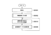
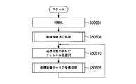
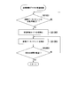
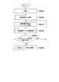
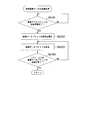
- the processing procedure of the wireless connection process in which the communication part with which the image transmission apparatus which comprises the image transmission system in the 1st Embodiment of this invention was equipped establishes the wireless connection between the image reception apparatuses which comprise an image transmission system is shown. It is a flowchart. It is the flowchart which showed the process sequence of the communication part with which the image receiver which comprises the image transmission system in the 1st Embodiment of this invention was equipped.
- the processing procedure of the wireless connection process in which the communication part with which the image receiving apparatus which comprises the image transmission system in the 1st Embodiment of this invention was equipped establishes the wireless connection between the image transmission apparatuses which comprise an image transmission system is shown. It is a flowchart.
- FIG. 1 is a diagram for explaining the schematic operation of the image transmission system according to the first embodiment of the present invention.
- FIG. 1 is a bird's-eye view of an image transmission device 100 and an image reception device 200 that constitute the image transmission system 1 according to the first embodiment of the present invention.
- the image transmission device 100 wirelessly transmits (transmits) captured image data of an image captured by the imaging unit to the image reception device 200 using wireless communication technology, and the image reception device 200 transmits the image.
- the image display system displays an image (display image) corresponding to captured image data wirelessly transmitted (transmitted) from the apparatus 100 on a display unit.
- the image transmission system 1 first, an operation of establishing a wireless connection is performed between the image transmission device 100 and the image reception device 200. At this time, the image receiving apparatus 200 transmits a response signal corresponding to the connection request from the image transmitting apparatus 100 to the image transmitting apparatus 100 until the wireless connection with the image transmitting apparatus 100 is established.
- the image reception device 200 waits for reception of the captured image data until wireless transmission (transmission) of the captured image data by the image transmission device 100 is started. .
- the image receiving apparatus 200 uses the time when the wireless connection with the image transmitting apparatus 100 is established as a reference time (for example, time 0), and based on a reference clock signal (hereinafter referred to as “reference clock signal”). Then, the measurement of the elapsed time is started.
- each of the image transmission device 100 and the image reception device 200 monitors interference by another wireless communication device with respect to the currently used wireless communication channel after the wireless connection is established, that is, the quality of the wireless communication.
- the wireless communication channel is always selected and switched so that wireless transmission can be performed using a channel with good communication quality.
- the image receiving device 200 receives the transmitted captured image data.
- the image transmission device 100 transmits captured image data captured by the imaging unit included in the image transmission device 100 and a vertical synchronization signal indicating the start or end of the effective period of the captured image data. Therefore, the image receiving device 200 receives the captured image data and the vertical synchronization signal transmitted from the image transmitting device 100.
- the image transmission apparatus 100 is not limited to a configuration that transmits captured image data in units of each frame captured by the imaging unit. For example, the image transmission device 100 captures captured image data of one frame captured by the imaging unit.
- a configuration may be employed in which a plurality of blocks are divided and packets corresponding to the divided blocks (hereinafter referred to as “image data packets”) are sequentially transmitted.
- the image transmission device 100 sequentially transmits one synchronization packet indicating one specific time point during the effective period of the captured image data instead of the vertical synchronization signal, and sequentially transmits the image data packet.
- the transmission is performed at the timing (for example, the timing at which transmission of the first image data packet is started or the timing at which transmission of the last image data packet is ended).
- FIG. 1 shows a state in which the image transmission device 100 is transmitting transmission image data TrD to the image reception device 200.
- the image reception device 200 When receiving the transmission image data TrD transmitted from the image transmission device 100, the image reception device 200 estimates the timing at which the image transmission device 100 captures an image by the imaging unit according to the following procedure, and the estimation result Based on the above, an adjustment instruction signal for adjusting the imaging timing in the image transmission device 100 is transmitted to the image transmission device 100.
- FIG. 1 shows a state in which the image receiving device 200 is transmitting the adjustment instruction signal TrA to the image transmitting device 100.
- the received time is set as the reception time of each captured image data. More specifically, the image reception device 200 receives the vertical synchronization signal included in the transmission image data TrD from the time when the wireless connection with the image transmission device 100 is established as a reference time (for example, time 0). The elapsed time until the reception is set as the reception time of the captured image data received this time.
- the image receiving apparatus 200 associates the order of the captured image data transmitted from the image transmitting apparatus 100 with the transmission image data TrD (hereinafter referred to as “captured image data order”) with the reception time.
- the image reception device 200 is transmitted from the image transmission device 100.
- the elapsed time until the synchronization packet included in the transmission image data TrD is received is the reception time when the captured image data is received.
- the elapsed time until the predetermined number of image data packets are received may be the reception time when the captured image data is received.
- the image receiving apparatus 200 determines the minimum reception time (hereinafter, “the order of the captured image data of each captured image data) and the reception time associated with the captured image data order”. “Minimum reception time”) and the reception time of the captured image data with the smallest change in reception time (hereinafter referred to as “minimum change reception time”). More specifically, when the image receiving device 200 receives the captured image data of the first frame, the reception time of the captured image data of the first frame is set as the minimum reception time. Thereafter, when the image receiving device 200 receives the captured image data of the second frame, the reception time of the captured image data of the second frame, the reception time of the captured image data of the first frame, and Is the minimum change reception time.
- the image receiving apparatus 200 receives the captured image data of the third frame, the reception time of the captured image data of the third frame, the reception time of the captured image data of the second frame, Is compared with the minimum change reception time.
- the image receiving apparatus 200 The reception time is updated to the time difference between the reception time of the captured image data of the third frame and the reception time of the captured image data of the second frame, and this minimum change reception time is selected.
- the image reception device 200 has the minimum change. Do not update the reception time. That is, the time difference between the reception time of the captured image data of the second frame and the reception time of the captured image data of the first frame remains the minimum change reception time, and this minimum change reception time is selected.
- the image receiving apparatus 200 is based on the respective information of the selected reception time of the minimum reception time and the minimum change reception time and the order of the captured image data associated with each reception time.
- the period and phase at which the image transmission device 100 captures an image by the imaging unit is estimated.
- the image receiving apparatus 200 transmits an adjustment instruction signal TrA for instructing the adjustment of the period and phase at which the image transmitting apparatus 100 captures each image based on the estimated period and phase to the image transmitting apparatus 100.
- the image reception device 200 receives the captured image data of each frame on the time axis representing the elapsed time with the reference time when the wireless connection with the image transmission device 100 is established as the origin.
- Is represented based on the information of the captured image data order, and the selected minimum reception time and minimum change reception time are connected by a straight line.
- the slope of this straight line represents the period of the vertical synchronization signal included in each transmission image data TrD.
- the intercept between the straight line and the time axis indicates the phase of the vertical synchronization signal included in the transmission image data TrD that transmits the captured image data of the first frame after the wireless connection with the image transmission device 100 is established.
- the image reception device 200 is included when capturing an image of a frame other than the image of the frame represented by the captured image data corresponding to each of the selected minimum reception time and minimum change reception time, for example, image transmission
- the influence of factors other than the delay of wireless transmission such as an error between the reference clock signal generated by the crystal oscillation IC provided in the apparatus 100 and the reference clock signal generated by the crystal oscillation IC provided in the image receiving apparatus 200, is estimated. That is, the image reception device 200 represents the reception time of each captured image data on the time axis, and transmits the image based on the slope and intercept of the straight line connecting the selected minimum reception time and the minimum change reception time.
- the period and phase of the vertical synchronization signal in the apparatus 100 are estimated.
- the image receiving apparatus 200 generates an adjustment instruction signal TrA for adjusting the period and phase of the vertical synchronizing signal generated by the image transmitting apparatus 100 based on the estimated period and phase of the vertical synchronizing signal. Send to.
- the image transmission device 100 generates a vertical synchronization signal based on the reference clock signal generated by the crystal oscillation IC included in the image transmission device 100 in accordance with the adjustment instruction signal TrA transmitted from the image reception device 200. , And the timing at which the image receiving apparatus 200 displays the captured image data wirelessly transmitted on the display unit.
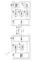
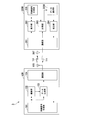
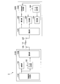
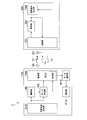
- FIG. 2 is a block diagram showing a schematic configuration of the image transmission system 1 according to the first embodiment of the present invention.
- the image transmission system 1 includes the image transmission device 100 and the image reception device 200.
- the image transmission apparatus 100 includes a synchronization signal generation unit 101, an imaging unit 102, a data generation unit 103, a communication unit 104, and an antenna 105.
- the image receiving apparatus 200 includes a communication unit 201, a display unit 202, a measurement unit 203, an estimation unit 204, a synchronization signal generation unit 205, a data selection unit 206, and an antenna 207.
- the synchronization signal generation unit 101 starts or ends the effective period of the captured image data that the imaging unit 102 captures and outputs based on a reference clock signal generated by a crystal oscillation IC (not illustrated) provided in the image transmission apparatus 100.
- the vertical synchronization signal shown is generated.
- the synchronization signal generation unit 101 outputs the generated vertical synchronization signal to each of the imaging unit 102 and the data generation unit 103.
- the synchronization signal generation unit 101 is input when an instruction to adjust the cycle or phase of the vertical synchronization signal is input from the communication unit 104 by the adjustment instruction signal TrA transmitted from the image reception device 200.
- the synchronization signal generation unit 101 may include a crystal oscillation IC (not shown) that generates a reference clock signal.
- the imaging unit 102 sequentially performs imaging processing at a timing based on (synchronized with) the vertical synchronization signal output from the synchronization signal generation unit 101. More specifically, the imaging unit 102 is connected to a solid-state imaging device (not shown) such as a CMOS (Complementary Metal-Oxide Semiconductor) image sensor. The imaging unit 102 controls the driving of the connected solid-state imaging device (not shown) based on the vertical synchronization signal output from the synchronization signal generation unit 101, that is, the imaging operation of the solid-state imaging device (not shown) is performed. Controlled, and sequentially outputs captured image data of each frame image captured by a solid-state imaging device (not shown) to the data generation unit 103. In the following description, for ease of explanation, it is assumed that the imaging unit 102 performs imaging and sequentially outputs captured image data of each frame image to the data generation unit 103.
- CMOS Complementary Metal-Oxide Semiconductor
- the data generation unit 103 generates captured image data for wireless transmission of one frame including the vertical synchronization signal output from the synchronization signal generation unit 101 in the captured image data output from the imaging unit 102.
- the data generation unit 103 outputs the generated captured image data for wireless transmission of one frame to the communication unit 104.
- the image transmission device 100 is configured to wirelessly transmit captured image data of one frame into a plurality of image data packets
- the data generation unit 103 outputs each frame output from the imaging unit 102.
- Each of the image data packet obtained by dividing the captured image data and one synchronization packet indicating a specific point in time during the effective period of the captured image data represented by the vertical synchronization signal output from the synchronization signal generation unit 101 are generated.
- the data generation unit 103 outputs the generated synchronization packet to the communication unit 104 immediately before outputting the first image data packet to the communication unit 104 or immediately after outputting the last image data packet to the communication unit 104. To do.
- the communication unit 104 performs wireless communication as transmission image data TrD for transmitting the captured image data for wireless transmission output from the data generation unit 103 by wireless transmission using a wireless connection established with the image receiving device 200.
- the image is transmitted to the image receiving apparatus 200 via the antenna 105.
- the communication unit 104 is for wireless transmission output from the data generation unit 103.
- Each transmission image data TrD corresponding to the synchronization packet or the image data packet included in the captured image data is transmitted as one packet to the image receiving apparatus 200 via the antenna 105 for wireless communication.
- the communication unit 104 receives the adjustment instruction signal TrA transmitted from the image receiving apparatus 200 via the antenna 105 during the period when the transmission image data TrD is not transmitted to the image receiving apparatus 200, and receives the received adjustment.
- An instruction to adjust the cycle or phase of the vertical synchronization signal represented by the instruction signal TrA is output to the synchronization signal generation unit 101.
- the antenna 105 is an antenna for wireless communication for performing wireless communication with the image receiving apparatus 200.
- the antenna 105 transmits a radio signal corresponding to the transmission image data TrD output from the communication unit 104 to the image reception device 200. Further, the antenna 105 receives a radio signal corresponding to the adjustment instruction signal TrA transmitted from the image receiving apparatus 200 and outputs the received adjustment instruction signal TrA to the communication unit 104.
- the image transmission device 100 transmits captured image data of an image captured by the imaging unit 102 to the image reception device 200.
- the functions of the synchronization signal generation unit 101 and the data generation unit 103 included in the image transmission device 100 and the function of controlling the connected solid-state imaging device (not shown) in the imaging unit 102 are partly or entirely.
- the processor is realized by one processor or individual processors corresponding to the respective functions, that is, a plurality of processors.
- a part or all of the above-described functions of the image transmitting apparatus 100 may be realized by an integrated circuit such as a dedicated LSI (Large Scale Integration), so-called ASIC (Application Specific Integrated Circuit).
- the synchronization signal generation unit 205 processes one whole frame of captured image data transmitted from the image transmission device 100 based on a reference clock signal generated by a crystal oscillation IC (not shown) provided in the image reception device 200.
- a timing signal (hereinafter referred to as a “display timing signal”) serving as a reference for displaying an image, such as a clock signal having a frequency resolution of a refresh rate resolution capable of being displayed and a synchronization signal for display, is generated.
- the synchronization signal generation unit 205 outputs the generated display timing signal to each of the display unit 202 and the measurement unit 203.
- the synchronization signal generation unit 205 captures captured images included in each image data packet.
- Display timing signals such as a clock signal having a frequency resolution that can be processed for each block of data and a synchronization signal for display are generated and output to the display unit 202 and the measurement unit 203, respectively.
- the synchronization signal generation unit 205 may include a crystal oscillation IC (not shown) that generates a reference clock signal.
- the communication unit 201 receives the transmission image data TrD transmitted from the image transmission device 100 via the antenna 207.
- the communication unit 201 outputs captured image data included in the received transmission image data TrD to the display unit 202.
- the communication unit 201 outputs a vertical synchronization signal included in the received transmission image data TrD to the measurement unit 203.
- the communication unit 201 transmits each image included in the received transmission image data TrD.
- the data packet is output to the display unit 202, and the synchronization packet included in the received transmission image data TrD is output to the measurement unit 203.
- the communication unit 201 wirelessly transmits an adjustment instruction signal instructing adjustment of the period and phase of the vertical synchronization signal output from the estimation unit 204 in a period in which the transmission image data TrD is not received from the image transmission device 100.
- Adjustment instruction signal TrA is transmitted to the image transmission apparatus 100 via the antenna 207.
- the communication unit 201 performs an operation of establishing a wireless connection in response to a connection request transmitted from the communication unit 104 included in the image transmission device 100, and the wireless connection is established with the image transmission device 100. In some cases, a connection establishment signal indicating that a wireless connection has been established is output to the measurement unit 203.
- the antenna 207 is an antenna for wireless communication for performing wireless communication with the image transmission apparatus 100.
- the antenna 207 receives a radio signal corresponding to the transmission image data TrD transmitted from the image transmission apparatus 100, and outputs the received transmission image data TrD to the communication unit 201. Further, the antenna 207 transmits a radio signal corresponding to the adjustment instruction signal TrA output from the communication unit 201 to the image transmission device 100.
- the display unit 202 displays an image (display image) corresponding to the captured image data output from the communication unit 201 based on the display timing signal output from the synchronization signal generation unit 205. More specifically, the display unit 202 is connected to a display device (not shown) such as a liquid crystal display (LCD). The display unit 202 outputs the display image data corresponding to the captured image data output from the communication unit 201 to a liquid crystal display (not illustrated) at the timing of the display timing signal output from the synchronization signal generation unit 205, thereby A display image corresponding to the captured image data is displayed on the illustrated liquid crystal display. In the following description, for ease of explanation, the display unit 202 will be described as displaying a display image corresponding to the captured image data.
- the measurement unit 203 uses the timing at which the connection establishment signal is input as a reference time, and transmits an image based on the display timing signal output from the synchronization signal generation unit 205.
- the measurement of elapsed time after the wireless connection with the apparatus 100 is established is started.
- the measuring unit 203 then establishes the time until the vertical synchronization signal is input from the communication unit 201 after the wireless connection with the image transmission apparatus 100 is established, that is, after the measurement of the elapsed time is started, that is, the image transmission.
- the time until receiving the captured image data transmitted from the apparatus 100 is measured.
- the measurement unit 203 outputs the time until each measured vertical synchronization signal is input to the data selection unit 206 as information on the reception time of the captured image data.
- the measurement unit 203 determines the number of vertical synchronization signals output from the communication unit 201 after establishing a wireless connection with the image transmission device 100, that is, the number of captured image data transmitted from the image transmission device 100. Count. Then, the measuring unit 203 outputs the counted number of captured image data to the data selection unit 206 in association with the reception time information as information of the captured image data order.
- the measurement unit 203 can establish a wireless connection with the image transmission device 100.
- the time until the synchronization packet is input from the communication unit 201 is measured, and is output to the data selection unit 206 as information on the reception time of the captured image data.
- the measurement unit 203 counts the number of synchronization packets output from the communication unit 201 after the wireless connection with the image transmission apparatus 100 is established, and associates the information with the reception time information as the captured image data order information. To the data selection unit 206.
- the data selection unit 206 selects the minimum reception time from the information of the predetermined number of reception times output from the measurement unit 203 and associated with the information of the captured image data order. Further, the data selection unit 206, for each of the remaining reception times excluding the selected minimum reception time, when connecting the selected minimum reception time and each of the other reception times with a straight line, the slope of this line The reception time that minimizes the magnitude of the reception time, that is, the minimum change reception time that minimizes the period of the reception time is selected. Then, the data selection unit 206 selects each piece of information of the selected minimum reception time and minimum change reception time and the order of the captured image data corresponding to each of the minimum reception time and the minimum change reception time.
- the data selection unit 206 selects one set of captured image data with a small wireless transmission delay from the captured image data transmitted from the image transmitting apparatus 100, and corresponds to the selected set of captured image data. Each information of the reception time and the captured image data order is output to the estimation unit 204 as selection data.
- the estimation unit 204 Based on the information (selection data) of the reception time and the order of the captured image data corresponding to the set of captured image data output from the data selection unit 206, the estimation unit 204 causes the image transmission apparatus 100 to perform the imaging unit 102. To estimate the period and phase of the vertical synchronization signal representing the timing when the image is captured. Based on the estimated period and phase of the vertical synchronization signal, the estimation unit 204 subsequently uses the synchronization provided in the image transmission device 100 as a reference when the image transmission device 100 captures an image by the imaging unit 102. An adjustment instruction signal for adjusting the period and phase of the vertical synchronization signal generated by the signal generation unit 101 is output to the communication unit 201.
- the adjustment instruction signal output from the estimation unit 204 to the communication unit 201 includes a period adjustment instruction signal for instructing adjustment of the period of the vertical synchronization signal and a phase for instructing adjustment of the phase of the vertical synchronization signal. And an adjustment instruction signal. Therefore, the estimation unit 204 can instruct adjustment of one or both of the period and phase of the vertical synchronization signal.
- the adjustment instruction signal TrA is wirelessly transmitted to the image transmission apparatus 100 via the antenna 207 by the communication unit 201, and the image transmission apparatus 100 is synchronized according to the adjustment instruction signal TrA transmitted from the image reception apparatus 200.
- the signal generation unit 101 adjusts the period and phase of the vertical synchronization signal when the imaging unit 102 captures an image thereafter.
- the timing of the vertical synchronization signal generated by the synchronization signal generation unit 101 and the timing at which the display unit 202 displays the display image corresponding to the captured image data transmitted from the image transmission device 100 on the display unit 202. Can be matched.
- the display image according to the captured image data that the image transmission device 100 has captured and transmitted by the image capturing unit 102 is stably displayed by the display unit 202 provided in the image receiving device 200. can do.
- the image reception device 200 displays the captured image data of the image captured by the imaging unit 102 included in the image transmission device 100 on the display unit 202 (more specifically, the non-connection connected to the display unit 202). (Displayed on the liquid crystal display).
- the function of the synchronization signal generation unit 205 provided in the image receiving device 200, the function of the measurement unit 203, the data selection unit 206, and the estimation unit 204, and a liquid crystal display (not shown) connected to the display unit 202 are also provided.
- the function of outputting display image data in accordance with the captured image data to be output is realized by a part or all of the processor, and one processor or individual processors corresponding to the respective functions, that is, a plurality of processors. It may be. Further, a part or all of the above-described functions of the image receiving apparatus 200 may be realized by an integrated circuit such as a dedicated LSI (so-called ASIC).
- FIG. 3 is a timing chart showing an example of reception time of captured image data wirelessly transmitted in the image transmission system 1 according to the first embodiment of the present invention.
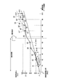
- FIG. 4 is a diagram illustrating an example of the relationship between the order of captured image data to be wirelessly transmitted and the reception time in the image transmission system 1 according to the first embodiment of the present invention.
- FIG. 3 shows an example of a state in which the image transmission apparatus 100 is transmitting ten pieces of transmission image data TrD including a vertical synchronization signal and captured image data.
- the measurement unit 203 included in the image reception device 200 uses each transmission image as a reference time based on the timing at which the connection establishment signal is input, that is, the timing at which the wireless connection with the image transmission device 100 is established. The time until the vertical synchronization signal included in the data TrD is received is measured as the reception time.
- the times are the reception time D1 to reception time D10 of the captured image data X1 to captured image data X10 included in the respective transmission image data TrD. More specifically, the reception time of the first vertical synchronization signal is the reception time D of the captured image data X1, the reception time of the second vertical synchronization signal is the reception time D2 of the captured image data X2,. Is the reception time D10 of the captured image data X10.
- the measurement unit 203 counts the number of received vertical synchronization signals as the order of the captured image data X included in each transmission image data TrD from the timing when the connection establishment signal is input.
- the number of received vertical synchronization signals is sequentially counted, and the counted number of vertical synchronization signals is taken as the captured image data X1 to captured image data X10 included in each transmission image data TrD.
- the measurement unit 203 associates each reception time D with the captured image data order N and outputs the result to the data selection unit 206.
- the data selection unit 206 based on the information associated with the reception time D output from the measurement unit 203 and the captured image data order N, the captured image data of the minimum reception time, and the minimum Each of the captured image data at the change reception time is selected. For example, consider a case where the data selection unit 206 receives the transmission image data TrD corresponding to the five captured image data X1 to the captured image data X5 as the period of the vertical synchronization signal or the phase estimation period. In this case, from the reception time D1 to reception time D5 and the captured image data order N1 to the captured image data order N5 corresponding to each of the five captured image data X1 to captured image data X5, Each of the captured image data at the minimum change reception time is selected. In the example shown in FIG. 3, the first captured image data X1 is selected as the captured image data at the minimum reception time, and the third captured image data X3 with a small delay is selected as the captured image data at the minimum change reception time.
- the data selection unit 206 includes a reception time D1 and captured image data order N1 corresponding to the selected first captured image data X1, and a reception time D3 and captured image data order N3 corresponding to the third captured image data X3. Each is output to the estimation unit 204 as selection data.
- the estimation unit 204 includes the minimum reception time and the captured image data order included in the selection data output from the data selection unit 206, and the minimum change reception time and the captured image data order. Based on this, the period and phase of the vertical synchronization signal when the image transmission apparatus 100 captures an image of each frame by the imaging unit 102 are estimated.
- the estimation unit 204 receives the reception time D1 and the captured image data order N1 corresponding to the first captured image data X1 output from the data selection unit 206, and the reception time D3 corresponding to the third captured image data X3.
- the period and phase of a vertical synchronizing signal are estimated based on each information with captured image data order N3.
- the estimation unit 204 estimates the period and phase of the vertical synchronization signal generated by the synchronization signal generation unit 101 included in the image transmission device 100. At this time, the estimation unit 204 represents the selection data on a graph as shown in FIG. 4 with the captured image data order as the X axis and the reception time as the Y axis.
- FIG. 4 in order to make it easy to understand the relationship between the reception time D and the captured image data order N in each received captured image data X, the reception times of the 10 captured image data X1 to captured image data X10. An example showing D1 to reception time D10 is shown.
- the estimation unit 204 obtains an inclination ⁇ of the straight line ⁇ represented by the following expression (1) and an intercept ⁇ between the Y axis and (N1, D1) and (N3, D3).
- the calculation process of the period and phase of the reception time is performed.
- the straight line ⁇ represented by the following expression (1) is the reception time in the selection data.
- N represents the order of captured image data.
- the slope ⁇ of the straight line ⁇ represented by the above equation (1) represents a change in the reception time D with respect to the number of the captured image data X
- the intercept ⁇ of the straight line ⁇ with respect to the Y axis represents the captured image data order.
- Represents the phase of the reception time when 0.
- the slope ⁇ of the straight line ⁇ represents the estimated period of the vertical synchronization signal
- the time difference of the reception time D that is, the difference of the synchronization shift time
- N is obtained by dividing by the frame interval.
- the slope ⁇ of the straight line ⁇ is expressed by the following equation (2).
- equation (2) by dividing the difference between the reception time D3 and the reception time D1 (time difference between the reception times D) by the difference (frame interval) between the captured image data order N3 and the captured image data order N1, The slope ⁇ is obtained.
- the intercept ⁇ of the straight line ⁇ with respect to the Y axis represents the phase of the estimated vertical synchronization signal, and each received time D is weighted by the captured image data order N corresponding to the other received time D.
- the difference obtained as a result of multiplying by (frame interval weight) is divided by the difference (frame interval) in the captured image data order N.
- the intercept ⁇ of the straight line ⁇ with the Y axis is expressed by the following equation (3).
- the intercept ⁇ is obtained by dividing the difference from the result obtained by multiplying the order N1 by the frame interval weight by the difference (frame interval) between the captured image data order N3 and the captured image data order N1.
- the slope ⁇ of the straight line ⁇ is also referred to as “period ⁇ ”, and the intercept ⁇ of the straight line ⁇ with respect to the Y axis is also referred to as “phase ⁇ ”.
- the estimation unit 204 calculates a difference between the calculated period ⁇ and a predetermined target period ⁇ t based on the following equation (4), and instructs the adjustment of the period of the vertical synchronization signal based on the calculated difference value.
- the period adjustment instruction signal ⁇ for this purpose is used.
- the phase adjustment instruction signal ⁇ for instructing the adjustment of.
- each of the target cycle ⁇ t and the phase ⁇ t corresponds to captured image data at a cycle of 60 frames / second (fps) on the display unit 202 provided in the image receiving device 200, for example.
- the estimation unit 204 outputs the period adjustment instruction signal ⁇ calculated by the above equation (4) and the phase adjustment instruction signal ⁇ calculated by the above equation (5) to the communication unit 201.
- the communication unit 201 transmits the adjustment instruction signal TrA including the period adjustment instruction signal ⁇ and the phase adjustment instruction signal ⁇ output from the estimation unit 204 to the image transmission apparatus 100 via the antenna 207. .
- the synchronization signal generation unit 101 included in the image transmission device 100 generates according to each of the period adjustment instruction signal ⁇ and the phase adjustment instruction signal ⁇ included in the adjustment instruction signal TrA transmitted from the image reception device 200. Adjust the period and phase of the vertical sync signal.
- the image transmission system 1 the period and phase of the display image of each frame corresponding to the captured image data X displayed on the display unit 202 by the image receiving device 200 and the adjustment instruction signal TrA are transmitted.
- the period and phase of the captured image data X of the frame that the image transmission apparatus 100 captures and transmits with the imaging unit 102 are synchronized.
- the timing at which the image transmission device 100 captures each image by the imaging unit 102 is the target for the image receiving device 200 to display a display image corresponding to the captured image data on the display unit 202.
- the image receiving apparatus 200 can stably display a display image corresponding to the captured image data on the display unit 202.
- the image receiving apparatus 200 transmits the adjustment instruction signal TrA to the image transmitting apparatus 100 at time T ⁇ b> 5 after receiving the fifth captured image data X ⁇ b> 5.
- the synchronization signal generation unit 101 generates the period of the vertical synchronization signal generated according to each of the period adjustment instruction signal ⁇ and the phase adjustment instruction signal ⁇ included in the adjustment instruction signal TrA, and When the phase is adjusted, the transmission image data TrD corresponding to each captured image data X is transmitted at an earlier timing than when the period and phase of the vertical synchronization signal are not adjusted.
- the period or phase is set to be higher than the reception time at which the image receiving apparatus 200 receives the captured image data X7 ′ captured with reference to the vertical synchronization signal whose period and phase are not adjusted.
- the image reception device 200 receives the captured image data X8 ′ to the captured image data X10 ′ captured with reference to a vertical synchronization signal whose period and phase are not adjusted.
- the reception time D8 to the reception time D10 for receiving the captured image data X8 to the captured image data X10 captured with reference to the vertical synchronization signal whose period and phase are adjusted is earlier than the reception time by the time d8 to the time d10. Shows the case.
- FIG. 4 in order to make it easier to understand when the image receiving apparatus 200 does not adjust the period and phase of the vertical synchronization signal and when the period and phase of the vertical synchronization signal are adjusted, reception in each case is performed.
- An example of transition at time D is shown. More specifically, in FIG. 4, when the image receiving apparatus 200 receives captured image data X7 ′ to captured image data X10 ′ captured with reference to a vertical synchronization signal whose period or phase is not adjusted, in graph G1.
- An example of transition of reception time D in FIG. 4 an example of transition of the reception time D when the image reception device 200 receives the captured image data X7 to the captured image data X10 captured with reference to the vertical synchronization signal whose period and phase are adjusted is shown in the graph G2.
- the synchronization signal generation unit 101 provided in the image receiving apparatus 200 generates vertical synchronization according to each of the period adjustment instruction signal ⁇ and the phase adjustment instruction signal ⁇ included in the adjustment instruction signal TrA.
- the reception time D7 to the reception time D10 of the captured image data X7 to the captured image data X10 become closer to the straight line ⁇ .
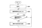
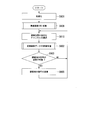
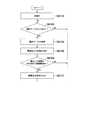
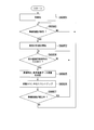
- FIG. 5 is a flowchart illustrating a processing procedure of the synchronization signal generation unit 101 included in the image transmission device 100 included in the image transmission system 1 according to the first embodiment of the present invention.
- the synchronization signal generation unit 101 generates and outputs a vertical synchronization signal by the following processing procedure.
- the synchronization signal generation unit 101 When the image transmission apparatus 100 is activated, the synchronization signal generation unit 101 first initializes the components in the synchronization signal generation unit 101 (step S201).
- the synchronization signal generation unit 101 generates a vertical synchronization signal based on a reference clock signal generated by a crystal oscillation IC (not shown) provided in the image transmission apparatus 100. Then, the synchronization signal generation unit 101 outputs the generated vertical synchronization signal to each of the imaging unit 102 and the data generation unit 103 (step S202). At this time, the vertical synchronization signal generated and output by the synchronization signal generation unit 101 is a vertical synchronization signal corresponding to a predetermined period or phase setting.
- the synchronization signal generation unit 101 confirms whether or not the adjustment instruction signal TrA is transmitted from the image reception device 200 (step S203). That is, the synchronization signal generation unit 101 confirms whether or not it is necessary to correct the cycle and phase of the generated vertical synchronization signal.
- step S203 If the adjustment instruction signal TrA has not been transmitted as a result of the confirmation in step S203 (“NO” in step S203), the synchronization signal generation unit 101 returns to step S202 and responds to a predetermined cycle or phase setting. The next vertical synchronization signal is generated, and the generated next vertical synchronization signal is output to each of the imaging unit 102 and the data generation unit 103.
- the synchronization signal generation unit 101 adjusts the cycle and phase settings of the generated vertical synchronization signal.
- the setting is changed according to the period adjustment instruction signal ⁇ and the phase adjustment instruction signal ⁇ included in the instruction signal TrA (step S204).
- the synchronization signal generation unit 101 returns to step S202 to generate the next vertical synchronization signal according to the changed cycle and phase settings, and the imaging unit 102 and the data generation unit for the generated next vertical synchronization signal.
- the output to each of 103 is repeated.
- the synchronization signal generation unit 101 sequentially generates the vertical synchronization signal, and sequentially outputs the generated vertical synchronization signal to each of the imaging unit 102 and the data generation unit 103.
- FIG. 6 is a flowchart illustrating a processing procedure of the imaging unit 102 provided in the image transmission device 100 configuring the image transmission system 1 according to the first embodiment of the present invention.
- the imaging unit 102 captures an image by the following processing procedure and outputs captured image data.
- the imaging unit 102 When the image transmitting apparatus 100 is activated, first, the imaging unit 102 initializes the components in the imaging unit 102 (step S301).
- the imaging unit 102 checks whether or not the vertical synchronization signal is output from the synchronization signal generation unit 101 (step S303). That is, the imaging unit 102 confirms whether or not it is time to capture an image.
- step S303 when the vertical synchronization signal is not output from the synchronization signal generation unit 101 ("NO" in step S303), the imaging unit 102 returns to step S303 and receives the vertical signal from the synchronization signal generation unit 101. Wait for sync signal output.
- step S303 when the vertical synchronization signal is output from the synchronization signal generation unit 101 (“YES” in step S303), the imaging unit 102 captures an image (step S304). More specifically, the imaging unit 102 drives a solid-state imaging device (not shown) at a timing based on the vertical synchronization signal, and executes an image imaging operation by the solid-state imaging device (not shown).
- the imaging unit 102 generates captured image data corresponding to the captured image. Then, the imaging unit 102 outputs the generated captured image data to the data generation unit 103 (step S302). Thereafter, the imaging unit 102 returns to step S303 and repeats imaging of an image at a timing based on the vertical synchronization signal, generation of captured image data corresponding to the captured image, and output to the data generation unit 103. .
- the imaging unit 102 sequentially repeats imaging of images at a timing based on the vertical synchronization signal, and sequentially outputs the generated captured image data to the data generation unit 103.
- FIG. 7 is a flowchart illustrating a processing procedure of the data generation unit 103 included in the image transmission device 100 included in the image transmission system 1 according to the first embodiment of the present invention.
- the data generation unit 103 generates and outputs captured image data for wireless transmission in the following processing procedure.
- the data generation unit 103 initializes the components in the data generation unit 103 (step S401).
- the data generation unit 103 acquires the vertical synchronization signal output from the synchronization signal generation unit 101 (step S402).
- the data generation unit 103 acquires the captured image data output from the imaging unit 102, and generates captured image data for wireless transmission of one frame including the vertical synchronization signal acquired in step S402. The data generation unit 103 then outputs the generated captured image data for wireless transmission of one frame to the communication unit 104 (step S404).
- the data generation unit 103 outputs one frame output from the imaging unit 102.
- Each of the image data packet obtained by dividing the captured image data and one synchronization packet representing the timing of the vertical synchronization signal output from the synchronization signal generation unit 101 are generated.
- the data generation unit 103 sequentially outputs captured image data for wireless transmission of one frame obtained by adding a synchronization packet to the generated image data packet to the communication unit 104.
- the data generation unit 103 checks whether or not all the output of the generated captured image data for wireless transmission of one frame has been completed (step S403). That is, it is confirmed whether or not the output of all the captured image data for one frame imaged by the imaging unit 102 is completed with the vertical synchronization signal generated by the synchronization signal generation unit 101 as a reference.
- step S403 if all the output of the generated captured image data for wireless transmission of one frame has not been completed (“NO” in step S403), the data generation unit 103 returns to step S404. Then, output of the generated image data for wireless transmission of one frame to the communication unit 104 is continued.
- step S403 if all the output of the generated captured image data for wireless transmission of one frame has been completed (“YES” in step S403), the data generation unit 103 proceeds to step S402. Returning, the vertical synchronization signal corresponding to the next frame is acquired from the synchronization signal generation unit 101. That is, the data generation unit 103 generates and outputs captured image data for wireless transmission of the next frame in steps S402 and S404.
- the data generation unit 103 includes the captured image data for wireless transmission of each frame including the vertical synchronization signal output from the synchronization signal generation unit 101 in the captured image data output from the imaging unit 102.
- the generation and output to the communication unit 104 are repeated.
- FIG. 8 is a flowchart illustrating a processing procedure of the communication unit 104 included in the image transmission device 100 included in the image transmission system 1 according to the first embodiment of the present invention.
- the communication unit 104 transmits captured image data for wireless transmission, that is, transmission image data TrD to the image receiving apparatus 200 and an adjustment instruction signal TrA transmitted from the image receiving apparatus 200 in the following processing procedure. And receive.
- the communication unit 104 When the image transmission device 100 is activated, the communication unit 104 first initializes the components in the communication unit 104 (step S501).
- the communication unit 104 performs wireless connection (TX) processing on a channel of wireless communication with the image reception device 200 (more specifically, the communication unit 201 included in the image reception device 200) via the antenna 105. This is performed (step S502).
- TX wireless connection
- the communication unit 104 can be used at present, that is, a channel with good (relatively good) communication quality from among available channels. Is selected (step S510).
- the communication unit 104 wirelessly transmits the captured image data for wireless transmission output from the data generation unit 103 to the communication unit 201 via the antenna 105 using the selected wireless communication channel.
- Data TrD transmission processing is performed (step S508).
- the communication unit 104 uses the wireless communication channel with good communication quality for the captured image data captured and output by the imaging unit 102 and the vertical synchronization signal generated by the synchronization signal generation unit 101. Over the air. Detailed description regarding the processing procedure of the transmission processing of the transmission image data TrD performed by the communication unit 104 in step S508 will be described later.
- the communication unit 104 determines whether or not the adjustment instruction signal TrA transmitted from the image receiving device 200 (more specifically, the communication unit 201 provided in the image receiving device 200) can be received. (Step S503). That is, the communication unit 104 confirms whether or not the present time is a period during which the transmission image data TrD is not transmitted to the image reception device 200.
- step S503 when the adjustment instruction signal TrA transmitted from the communication unit 201 cannot be received (“NO” in step S503), the communication unit 104 returns to step S510 and has good communication quality. Select a channel. That is, the communication unit 104 performs transmission processing of the transmission image data TrD corresponding to the captured image data of the next frame in the wireless communication channel with good communication quality in step S510 and step S508.
- step S503 when the adjustment instruction signal TrA transmitted from the communication unit 201 can be received (“YES” in step S503), the communication unit 104 has been transmitted from the communication unit 201.
- the adjustment instruction signal TrA is received (step S504).
- the communication unit 104 outputs to the synchronization signal generation unit 101 the adjustment instruction for the period and phase of the vertical synchronization signal included in the received adjustment instruction signal TrA, that is, the period adjustment instruction signal ⁇ and the phase adjustment instruction signal ⁇ . . Thereafter, the communication unit 104 returns to step S510.
- the synchronization signal generation unit 101 sets the cycle and phase of the vertical synchronization signal to be generated in step S204 in the processing procedure of the synchronization signal generation unit 101 illustrated in FIG.
- the setting is changed according to each of the signals ⁇ , and the period and phase of the generated vertical synchronization signal are set to the period and phase according to the period adjustment instruction signal ⁇ and the phase adjustment instruction signal ⁇ .
- the communication unit 104 wirelessly transmits the captured image data for wireless transmission output from the data generation unit 103 as transmission image data TrD, and the adjustment instruction signal transmitted from the image receiving device 200.
- the process of receiving TrA and outputting it to the synchronization signal generator 101 is repeated.
- the communication unit 104 may receive the adjustment instruction signal TrA in step S503.
- a process for receiving the transmitted adjustment instruction signal TrA in step S504 The procedure was shown. That is, the processing procedure in the case where the communication unit 104 receives the adjustment instruction signal TrA transmitted from the image receiving device 200 during the period when the transmission image data TrD is not transmitted to the image receiving device 200 is shown.
- the transmission of the transmission image data TrD and the reception of the adjustment instruction signal TrA can be performed at the same time.
- the channel for transmitting the transmission image data TrD from the image transmission device 100 to the image reception device 200 and the channel for transmitting the adjustment instruction signal TrA from the image reception device 200 to the image transmission device 100 are different wireless communication channels.
- the communication unit 104 transmits the transmission image data TrD and the adjustment instruction signal TrA at the same time in the process of transmitting the captured image data (transmission image data TrD) for wireless transmission to the image reception device 200. You may go.
- FIG. 9 is a flowchart illustrating a processing procedure of transmission processing in which the communication unit 104 included in the image transmission device 100 included in the image transmission system 1 according to the first embodiment of the present invention transmits the transmission image data TrD.
- the communication unit 104 transmits the transmission image data TrD to the image reception device 200 by the following processing procedure.
- the image transmission device 100 divides the captured image data of one frame into a plurality of image data packets in order to describe the processing procedure of the transmission processing of the transmission image data TrD in the communication unit 104 in detail.
- the wireless transmission is configured.
- the captured image data for wireless transmission output from the data generation unit 103 is output from an image data packet obtained by dividing one frame of captured image data output from the imaging unit 102 and the synchronization signal generation unit 101.
- one synchronization packet representing the timing of the vertical synchronization signal is included.
- the communication unit 104 When the communication unit 104 starts transmission processing of the transmission image data TrD in step S508, first, the communication unit 104 transmits the synchronization packet included in the wireless transmission captured image data output from the data generation unit 103 to the image reception device 200 (more specifically, In step S1205, it is checked whether preparation for transmission to the communication unit 201 provided in the image receiving apparatus 200 is completed.
- step S1205 when preparation for transmitting the synchronization packet included in the captured image data for wireless transmission output from the data generation unit 103 to the communication unit 201 is not completed ("NO" in step S1205), the communication unit 104 ends the transmission process of the transmission image data TrD, and continues to step S503 in the process of transmitting the captured image data for wireless transmission (transmission image data TrD) illustrated in FIG. 8 to the image reception device 200.
- step S503 in the process of transmitting the captured image data for wireless transmission (transmission image data TrD) illustrated in FIG. 8 to the image reception device 200.
- step S1205 when preparation for transmitting the synchronization packet included in the captured image data for wireless transmission output from the data generation unit 103 to the communication unit 201 is completed (“YES” in step S1205), the communication unit 104 transmits the transmission image data TrD corresponding to the synchronization packet included in the captured image data for wireless transmission output from the data generation unit 103 to the communication unit 201 as one packet (step S1206).
- the communication unit 104 confirms whether or not the preparation for transmitting the image data packet included in the captured image data for wireless transmission output from the data generation unit 103 is completed to the communication unit 201 (step S1201). .
- step S1201 when preparation for transmitting the image data packet included in the captured image data for wireless transmission output from the data generation unit 103 to the communication unit 201 is not completed ("NO" in step S1201)
- the communication unit 104 returns to step S1201 and waits for completion of preparation for transmission of the image data packet.
- step S1201 when preparation for transmitting the image data packet included in the captured image data for wireless transmission output from the data generation unit 103 to the communication unit 201 is completed (“YES” in step S1201).
- the communication unit 104 starts transmitting the transmission image data TrD corresponding to the image data packet included in the captured image data for wireless transmission output from the data generation unit 103 (step S1202).
- the communication unit 104 transmits the transmission image data TrD corresponding to the image data packet included in the captured image data for wireless transmission output from the data generation unit 103 to the communication unit 201 as one packet (step S1203).
- the communication unit 104 sequentially transmits the packets of the transmission image data TrD to the communication unit 201 from the first image data packet included in the captured image data for wireless transmission output from the data generation unit 103.
- the communication unit 104 confirms whether or not the transmission of the transmission image data TrD corresponding to all the image data packets included in the wireless transmission captured image data output from the data generation unit 103 is completed (Ste S1204). That is, it is confirmed whether or not transmission of all the captured image data for one frame imaged by the imaging unit 102 to the communication unit 201 has been completed using the vertical synchronization signal generated by the synchronization signal generation unit 101 as a reference.
- step S1204 when transmission of the transmission image data TrD corresponding to all the image data packets included in the captured image data for wireless transmission output from the data generation unit 103 has not been completed (“ NO "), the communication unit 104 returns to step S1203 and transmits the packet of the transmission image data TrD corresponding to the next image data packet to the communication unit 201.
- step S1204 transmission of the transmission image data TrD corresponding to all the image data packets included in the captured image data for wireless transmission output from the data generation unit 103 is completed (“ YES ”), the communication unit 104 ends the transmission process of the transmission image data TrD and continues the process of transmitting the captured image data for wireless transmission (transmission image data TrD) shown in FIG. The process returns to step S503.
- the communication unit 104 performs transmission processing for wirelessly transmitting the captured image data for wireless transmission output from the data generation unit 103 as transmission image data TrD.
- the image transmission apparatus 100 is configured to divide the captured image data of one frame into a plurality of image data packets and wirelessly transmit the image data packets.
- the image transmission device 100 is configured to wirelessly transmit captured image data in units of one frame image captured by the imaging unit 102 included in the image transmission device 100
- the data is output from the data generation unit 103.
- transmission image data TrD corresponding to the captured image data is transmitted to the communication unit 201. It will be.
- the transmission processing of the transmission image data TrD in the communication unit 104 in this case does not perform, for example, Step S1205 and Step S1206 in the transmission processing of the transmission image data TrD illustrated in FIG. Can be easily understood by considering as captured image data of one frame. More specifically, the communication unit 104 is ready to transmit the captured image data for wireless transmission of one frame including the vertical synchronization signal output from the data generation unit 103 to the communication unit 201 in step S1201. It can be easily understood by confirming whether or not the transmission has been completed and transmitting the transmission image data TrD corresponding to the captured image data of one frame to the communication unit 201 in the subsequent processing. Therefore, detailed description in the case where the image transmission apparatus 100 is configured to wirelessly transmit captured image data in units of one frame image will be omitted.
- FIG. 10 shows that the communication unit 104 included in the image transmission device 100 constituting the image transmission system 1 according to the first embodiment of the present invention establishes a wireless connection with the image reception device 200 constituting the image transmission system 1. It is the flowchart which showed the process sequence of the radio
- the communication unit 104 establishes a wireless connection with the image receiving device 200 in the following processing procedure.
- the communication unit 104 sets a channel number I of a wireless communication channel for which a wireless connection is attempted (step S1301).
- the communication unit 104 transmits a connection request packet for requesting a wireless connection to the image receiving apparatus 200 using the wireless communication channel having the set channel number I (step S1303).
- the communication unit 104 confirms whether or not it has received a connection response packet indicating that a connection request has been received, transmitted from the image receiving apparatus 200 in response to the connection request packet transmitted in step S1303 ( Step S1304).
- step S1304 when a connection response packet is received from the image reception device 200 (“YES” in step S1304), the communication unit 104 determines that a wireless connection with the image reception device 200 has been established. Then, the wireless connection (TX) process is terminated, and the process returns to the subsequent step S510 in the process of transmitting the captured image data (transmission image data TrD) for wireless transmission shown in FIG.
- step S1304 when the connection response packet from the image receiving apparatus 200 has not been received (“NO” in step S1304), the communication unit 104 transmits the connection request packet in step S1303. It is determined whether a predetermined time, a so-called timeout time has elapsed (step S1305).
- step S1305 As a result of the determination in step S1305, when the predetermined time has not elapsed (“NO” in step S1305), the communication unit 104 returns to step S1304 and confirms again whether or not the connection response packet has been received. .
- step S1307 “NO”)
- the communication unit 104 performs wireless connection (TX) processing for establishing a wireless connection with the image reception device 200 (more specifically, the communication unit 201 included in the image reception device 200). I do.
- TX wireless connection
- FIG. 11 is a flowchart illustrating a processing procedure of the communication unit 201 included in the image reception device 200 included in the image transmission system 1 according to the first embodiment of the present invention.
- the communication unit 201 instructs the reception of the transmission image data TrD transmitted from the image transmission apparatus 100 in the following processing procedure, that is, the vertical synchronization signal and the captured image data, and the adjustment of the period and phase of the vertical synchronization signal.
- the adjustment instruction signal TrA for transmission to the image transmission device 100 is transmitted.
- the communication unit 201 initializes the components in the communication unit 201 (step S601).
- the communication unit 201 performs wireless connection (RX) processing in a channel of wireless communication with the image transmission device 100 (more specifically, the communication unit 104 included in the image transmission device 100) via the antenna 207. This is performed (step S608).
- RX wireless connection
- the communication unit 201 can be used at present, that is, a channel with good (relatively good) communication quality from among available channels. Is selected (step S610).
- the process of step S610 is executed in cooperation with the channel selection process of step S510 in the communication unit 104 shown in FIG.
- the communication unit 201 selects a channel to be used based on the information about the channel with good communication quality selected and transmitted by the communication unit 104. Will change.
- the communication unit 201 when the communication unit 201 mainly selects a channel with good communication quality, the communication unit 201 selects a channel with good communication quality and transmits information on the selected channel with good communication quality to the communication unit 104. . Accordingly, the communication unit 104 changes the channel to be used based on the information on the channel with good communication quality transmitted from the communication unit 201 in the channel selection processing in step S510 in the communication unit 104 illustrated in FIG. Will do.
- the communication unit 201 performs reception processing of the transmission image data TrD, which receives the transmission image data TrD transmitted from the communication unit 104 via the antenna 207 using the selected wireless communication channel (Ste S602). That is, the communication unit 201 synchronizes with captured image data that is wirelessly transmitted from the communication unit 104 and captured and output by the imaging unit 102 included in the image transmission apparatus 100 using a wireless communication channel with good communication quality. The vertical synchronization signal generated by the signal generation unit 101 is received. Then, the communication unit 201 outputs captured image data included in the received transmission image data TrD to the display unit 202, and outputs a vertical synchronization signal included in the received transmission image data TrD to the measurement unit 203. A detailed description of the processing procedure of the reception processing of the transmission image data TrD performed by the communication unit 201 in step S602 will be described later.
- the communication unit 201 transmits the adjustment instruction signal output from the estimation unit 204 to the image transmission device 100 (more specifically, the communication unit 104 included in the image transmission device 100) as the adjustment instruction signal TrA. It is determined whether or not it can be performed (step S603). That is, the communication unit 201 confirms whether or not the present time is a period in which the transmission image data TrD transmitted from the image transmission device 100 is not received.
- step S603 If the result of determination in step S603 is that the adjustment instruction signal TrA cannot be transmitted to the communication unit 104 (“NO” in step S603), the communication unit 201 returns to step S610 to select a channel with good communication quality. Do. That is, the communication unit 201 performs the reception process of the transmission image data TrD corresponding to the captured image data of the next frame in the wireless communication channel with good communication quality in step S610 and step S602.
- step S603 when the adjustment instruction signal TrA can be transmitted to the communication unit 104 (“YES” in step S603), the communication unit 201 responds to the adjustment instruction signal output from the estimation unit 204.
- the adjustment instruction signal TrA is transmitted to the communication unit 104 (step S605). More specifically, the communication unit 201 receives an adjustment instruction signal TrA corresponding to the period or phase adjustment instruction of the vertical synchronization signal output from the estimation unit 204, that is, the period adjustment instruction signal ⁇ or the phase adjustment instruction signal ⁇ . To the communication unit 104. Thereafter, the communication unit 201 returns to step S610.
- the synchronization signal generation unit 101 included in the image transmission apparatus 100 adjusts the period and phase setting of the generated vertical synchronization signal in step S204 in the processing procedure of the synchronization signal generation unit 101 illustrated in FIG.
- the setting is changed according to each of the instruction signal ⁇ and the phase adjustment instruction signal ⁇ , and the period and phase of the generated vertical synchronization signal are changed to the period and phase according to the period adjustment instruction signal ⁇ and the phase adjustment instruction signal ⁇ .
- the communication unit 201 receives the transmission image data TrD transmitted from the image transmission device 100, and displays the captured image data included in the received transmission image data TrD on the display unit 202 and a vertical synchronization signal.
- the process of outputting to the measurement unit 203 and the process of wirelessly transmitting the adjustment instruction signal output from the estimation unit 204 as the adjustment instruction signal TrA are repeated.
- the communication unit 201 adjusts the adjustment instruction signal TrA in step S603.
- the adjustment instruction signal output from the estimation unit 204 in step S605 when the adjustment instruction signal TrA can be transmitted (“YES" in step S603).
- the processing procedure in the case of performing processing for transmitting the adjustment instruction signal TrA to the communication unit 104 is shown. That is, the processing procedure in the case where the communication unit 201 transmits the adjustment instruction signal TrA to the communication unit 104 during a period in which the transmission image data TrD transmitted from the image transmission apparatus 100 is not received is shown.
- the communication unit 201 receives the transmission image data TrD and transmits the adjustment instruction signal TrA in the process of receiving the transmission image data TrD (captured image data for wireless transmission) transmitted from the image transmission device 100. May be performed at the same time.
- FIG. 12 shows that the communication unit 201 provided in the image receiving device 200 constituting the image transmission system 1 in the first embodiment of the present invention establishes a wireless connection with the image transmitting device 100 constituting the image transmission system 1. It is the flowchart which showed the process sequence of the radio
- the communication unit 201 establishes a wireless connection with the image transmission device 100 in the following processing procedure.
- the communication unit 201 When the communication unit 201 starts the wireless connection (RX) process in step S608, the communication unit 201 first confirms whether or not a connection request packet transmitted from the image transmission apparatus 100 has been received (step S901).
- connection request packet from the image transmission device 100 is not received as a result of the confirmation in step S901 (“NO” in step S901)
- the communication unit 201 returns to step S901 and is transmitted from the image transmission device 100. Wait for the incoming connection request packet to be received.
- connection request packet from the image transmission apparatus 100 is received as a result of the confirmation in step S901 (“YES” in step S901)
- the communication unit 201 has received a connection request using the received connection request packet.
- a connection response packet is transmitted to the image transmission apparatus 100 (step S902).
- the communication unit 201 outputs a connection establishment signal indicating that a wireless connection with the image transmission apparatus 100 has been established to the measurement unit 203.
- the communication unit 201 establishes a wireless connection (RX) process for establishing a wireless connection with the image transmission device 100 (more specifically, the communication unit 104 included in the image transmission device 100). I do.
- RX wireless connection
- FIG. 13 is a flowchart illustrating a processing procedure of reception processing in which the communication unit 201 included in the image reception device 200 included in the image transmission system 1 according to the first embodiment of the present invention receives transmission image data TrD.
- the communication unit 201 receives the transmission image data TrD transmitted from the communication unit 104 included in the image transmission device 100 in the following processing procedure.
- the image transmission apparatus 100 divides the captured image data of one frame into a plurality of image data packets in order to describe the processing procedure of the reception processing of the transmission image data TrD in the communication unit 201 in detail.
- the wireless transmission is configured.
- the communication unit 201 is an image obtained by dividing each packet in the transmission image data TrD transmitted from the communication unit 104 from the captured image data of one frame captured by the imaging unit 102 included in the image transmission apparatus 100.
- the data packet is either one of the synchronization packets representing the timing of the vertical synchronization signal output from the synchronization signal generation unit 101. Then, in the reception processing of the transmission image data TrD in the communication unit 201, a case where a synchronization packet is received prior to reception of the first image data packet will be described.
- the communication unit 201 starts the reception process of the transmission image data TrD in step S602, first, the transmission image data transmitted from the image transmission device 100 (more specifically, the communication unit 104 included in the image transmission device 100).
- the TrD packet is received, and it is confirmed whether or not the received transmission image data TrD packet is a synchronization packet (step S1015).
- step S1015 when the received packet of the transmission image data TrD is not a synchronization packet (“NO” in step S1015), the communication unit 201 ends the reception processing of the transmission image data TrD, and FIG. The process returns to the subsequent step S603 in the process of receiving the transmission image data TrD (captured image data for wireless transmission) transmitted from the illustrated image transmission apparatus 100.
- step S1015 when the packet of the received transmission image data TrD is a synchronization packet (“YES” in step S1015), the communication unit 201 measures the received synchronization packet, that is, the vertical synchronization signal. It outputs to 203. Then, the communication unit 201 confirms whether or not preparation for receiving the image data packet transmitted from the communication unit 104 as a packet of the next transmission image data TrD is completed (step S1001).
- step S1001 If the result of confirmation in step S1001 is that preparation for receiving an image data packet transmitted as a packet of transmission image data TrD from the communication unit 104 has not been completed (“NO” in step S1001), the communication unit 201 The process returns to S1001 and waits for completion of preparation for receiving an image data packet.
- step S1001 when the preparation for receiving the image data packet transmitted as the transmission image data TrD packet from the communication unit 104 is completed (“YES” in step S1001), the communication unit 201 The reception time timer prepared for measuring the upper limit of the time required for wireless transmission of the captured image data for the frame is initialized (cleared), and measurement of the reception time is started (step S1002).
- the upper limit value of the time required for wireless transmission of captured image data for one frame is, for example, a display image corresponding to the captured image data by the image receiving device 200 at a cycle of 60 frames / second (fps). Is displayed, the time is 16.667 ms.
- the communication unit 201 transmits the first image data packet transmitted as one packet of the transmission image data TrD from the communication unit 104, that is, one frame captured by the imaging unit 102 included in the image transmission device 100.
- the first image data packet obtained by dividing the captured image data is received (step S1003).
- the communication unit 201 starts measuring the reception time in step S1002 based on the reception time measured by the reception time timer, and then determines a predetermined time, that is, one frame of captured image data. It is determined whether an upper limit time that can be used for wireless transmission has elapsed (step S1004). For example, when the image receiving apparatus 200 causes the display unit 202 to display a display image corresponding to the captured image data at a cycle of 60 frames / second (fps), the communication unit 201 determines whether or not the time of 16.667 ms has elapsed. Determine whether.
- step S1004 when the predetermined time has not elapsed (“NO” in step S1004), the communication unit 201 returns to step S1003 and transmits as one packet of transmission image data TrD from the communication unit 104. The next image data packet to be transmitted is received.
- step S1004 if a predetermined time has passed as a result of the determination in step S1004 (“YES” in step S1004), the communication unit 201 captures all the image data packets received in step S1003, that is, a captured image of one frame. Data is output to the display unit 202. And the communication part 201 complete
- the communication unit 201 wirelessly transmits each packet of the transmission image data TrD from the communication unit 104, and the captured image data of one frame captured by the imaging unit 102 included in the image transmission device 100.
- Each of the image data packets obtained by dividing the image data is sequentially received from the first image data packet.
- the image transmission device 100 is configured to wirelessly transmit captured image data of one frame by dividing it into a plurality of image data packets.
- the communication unit 201 includes a communication unit Transmission image data TrD corresponding to captured image data for wireless transmission of one frame including the vertical synchronization signal transmitted from 104 is received.
- the reception processing of the transmission image data TrD in the communication unit 201 is considered, for example, in step S1003 in the reception processing of the transmission image data TrD shown in FIG.
- the communication unit 201 easily understands by thinking that the transmission image data TrD corresponding to the captured image data of one frame is received after starting measurement of the reception time in step S1002. be able to. Therefore, detailed description of the image receiving device 200 when the image transmitting device 100 is configured to wirelessly transmit captured image data in units of one frame image is omitted.
- FIG. 14 is a flowchart illustrating a processing procedure of the synchronization signal generation unit 205 provided in the image reception device 200 included in the image transmission system 1 according to the first embodiment of the present invention.
- the synchronization signal generation unit 205 generates and outputs a display timing signal according to the following processing procedure.
- the synchronization signal generation unit 205 initializes the components in the synchronization signal generation unit 205 (step S1401).
- the synchronization signal generation unit 205 generates a display timing signal based on a reference clock signal generated by a crystal oscillation IC (not shown) provided in the image reception device 200. Then, the synchronization signal generation unit 205 outputs the generated display timing signal to each of the display unit 202 and the measurement unit 203 (step S1402). Thereafter, the synchronization signal generation unit 205 returns to step S1402, and repeats the process of generating and outputting the display timing signal.
- the display timing signal generated and output by the synchronization signal generation unit 205 corresponds to a vertical synchronization signal for a display image corresponding to captured image data displayed on a liquid crystal display (not shown) connected to the display unit 202. It may be a signal having a predetermined cycle or phase.
- the synchronization signal generation unit 205 repeatedly generates a display timing signal serving as a reference for displaying a display image corresponding to captured image data on a liquid crystal display (not illustrated), and generates the generated display timing signal. And output to each of the display unit 202 and the measurement unit 203.
- FIG. 15 is a flowchart showing a processing procedure of the display unit 202 provided in the image receiving device 200 constituting the image transmission system 1 according to the first embodiment of the present invention.
- the display unit 202 displays a display image corresponding to the captured image data in the following processing procedure.
- the display unit 202 When the image receiving apparatus 200 is activated, the display unit 202 first initializes the components in the display unit 202 (step S701).
- the display unit 202 confirms whether the captured image data received from the communication unit 201 is output (step S703). That is, the display unit 202 confirms whether there is captured image data of a display image to be displayed on a connected liquid crystal display (not shown).
- step S703 When the captured image data is not output from the communication unit 201 as a result of the confirmation in step S703 (“NO” in step S703), the display unit 202 returns to step S703 and outputs the captured image data from the communication unit 201. Wait for.
- step S703 when the captured image data is output from the communication unit 201 (“YES” in step S703), the display unit 202 displays 1 corresponding to the captured image data output from the communication unit 201.
- a display image of the frame is generated, and the generated display image data is output to a liquid crystal display (not shown) at a timing based on the display timing signal output from the synchronization signal generation unit 205 (step S704).
- a liquid crystal display displays an image corresponding to display image data output from the display unit 202.
- the display unit 202 returns to step S703 to generate a display image of one frame corresponding to the next captured image data output from the communication unit 201, and to a liquid crystal display (not shown) of the generated display image data. Repeat with the output.
- the display unit 202 generates one frame of display image corresponding to the captured image data output from the communication unit 201 at a timing based on the display timing signal output from the synchronization signal generation unit 205.
- the generated display image data is sequentially output to a liquid crystal display (not shown).
- FIG. 16 is a flowchart showing a processing procedure of the measurement unit 203 provided in the image receiving device 200 constituting the image transmission system 1 according to the first embodiment of the present invention.
- the measurement unit 203 measures the reception time of the captured image data included in the transmission image data TrD transmitted from the communication unit 104 included in the image transmission apparatus 100 and the captured image data order according to the following processing procedure. .
- the time measured by the measurement unit 203 will be described as time T
- the counter that counts the number of vertical synchronization signals for the measurement unit 203 to measure the order of captured image data will be described as an order counter C.
- the measurement unit 203 confirms whether or not a wireless connection with the image transmission device 100 has been established (step S803). More specifically, the measurement unit 203 confirms whether a connection establishment signal is input from the communication unit 201.
- step S803 if the wireless connection with the image transmission device 100 is not established (“NO” in step S803), the measurement unit 203 returns to step S803 and establishes a connection with the image transmission device 100. Wait for the wireless connection to be established.
- the measurement unit 203 confirms whether or not there is an input of a vertical synchronization signal (step S804). More specifically, the measurement unit 203 checks whether a vertical synchronization signal is input from the communication unit 201.
- step S804 If the result of the confirmation in step S804 is that there is no vertical synchronization signal input (“NO” in step S804), the measurement unit 203 returns to step S804 and waits for the vertical synchronization signal to be input.
- the measurement unit 203 measures the reception time and the captured image data order, and measures the received reception time and the captured image.
- the data order is linked and output to the data selection unit 206 (step S805). More specifically, the measurement unit 203 acquires the current time T as the reception time D. Further, the measurement unit 203 acquires the current count value of the order counter C, and sets the acquired count value + 1 of the order counter C as the captured image data order N. Then, the measurement unit 203 associates the reception time D with the captured image data order N and outputs the result to the data selection unit 206.
- the measuring unit 203 counts up the count value of the order counter C (step S806). More specifically, the measurement unit 203 updates the order counter C to the order counter C + 1.
- the measurement unit 203 confirms whether or not a wireless connection with the image transmission apparatus 100 is being established (step S807). That is, the measurement unit 203 confirms whether or not the state where the wireless connection with the image transmission device 100 is established continues.
- step S807 when the wireless connection with the image transmission apparatus 100 is being established (“YES” in step S807), the measurement unit 203 returns to step S804 and inputs the next vertical synchronization signal. Wait for it.
- step S807 if the wireless connection with the image transmission apparatus 100 is not established, that is, the wireless connection with the image transmission apparatus 100 is interrupted ("NO" in step S807), the measurement is performed.
- the unit 203 returns to step S803 and waits for establishment of a wireless connection with the image transmission device 100.
- the measurement unit 203 sequentially repeats measurement of the reception time of the captured image data included in the transmission image data TrD transmitted from the communication unit 104 included in the image transmission device 100 and the order of the captured image data.
- information on the measured reception time and the order of the captured image data is sequentially output to the data selection unit 206.
- one image captured by the image transmission device 100 included in the image transmission device 100 is captured by the image transmission device 100.
- the case where the captured image data is wirelessly transmitted in units of frame images has been described.
- the image transmitting apparatus 100 is configured to divide the captured image data of one frame into a plurality of image data packets and wirelessly transmit the captured image data, based on the synchronization packet output from the communication unit 201, Data reception time and captured image data order are measured.
- the measurement processing of the reception time of the captured image data and the captured image data order in the measurement unit 203 is considered to confirm whether or not a synchronization packet is input from the communication unit 201 in the process of step S804. Can be easily understood. Therefore, detailed description in the case where the image transmission apparatus 100 is configured to wirelessly transmit the captured image data of one frame by dividing it into a plurality of image data packets will be omitted.
- FIG. 17 is a flowchart showing a processing procedure of the data selection unit 206 provided in the image receiving apparatus 200 constituting the image transmission system 1 according to the first embodiment of the present invention.
- the data selection unit 206 selects each piece of information of the selection data from a predetermined number of pieces of reception time information associated with information on the order of captured image data in the following processing procedure.
- the data selection unit 206 initializes the components in the data selection unit 206 (step S1501).
- the data selection unit 206 confirms whether there is an input of a predetermined number of pieces of reception time information associated with information on the order of captured image data from the measurement unit 203 (step S1503). As a result of the confirmation in step S1503, when there is no input of information of a predetermined number of reception times associated with the information of the captured image data order (“NO” in step S1503), the data selection unit 206 proceeds to step S1503. The process waits until a predetermined number of pieces of information on the reception time associated with the information on the order of captured image data are input.
- step S1503 when there is a predetermined number of reception time information inputs associated with the captured image data order information ("YES" in step S1503), the data selection unit 206 performs measurement. Information of a predetermined number of reception times associated with information of the order of captured image data output from the unit 203 is acquired (step S1506).
- the data selection unit 206 determines the minimum reception time and the corresponding captured image data order information based on the predetermined number of reception time information associated with the captured image data order information acquired in step S1506. Then, a reception time selection process for selecting each of the minimum change reception time and the corresponding captured image data order information is performed (step S1504). More specifically, the data selection unit 206 first determines the minimum reception time and the information based on the predetermined number of reception times associated with the information of the captured image data order output from the measurement unit 203. The order of captured image data corresponding to the minimum reception time is selected.
- the data selection unit 206 estimates each information of the minimum reception time and the captured image data order selected in the reception time selection process in step S1504 and the minimum change reception time and the captured image data order as selection data. It outputs to 204 (step S1505). After that, the data selection unit 206 returns to step S1503, and the next minimum based on the information of the predetermined number of reception times associated with the information of the order of the captured image data output from the measurement unit 203 thereafter. The selection of the reception time and the captured image data order, the minimum change reception time and the captured image data order, and the output of the next selection data to the estimation unit 204 are repeated.
- the reception time information associated with the captured image data order information already used for selection of the selection data and the selection of the next selection data The reception time information associated with the predetermined number of pieces of the captured image data order information that is not used for selection of the selection data between the captured image data order information and the reception time information associated with the selected image data. May be provided. As a result, the information on the reception time associated with the information on the order of the captured image data in which the period and phase of the vertical synchronization signal based on the selection data output first is not adjusted is used for the next selection of the selection data. It can be avoided that the information of the image data order is included in the information of the reception time linked.
- the data selection unit 206 receives the minimum reception time and the minimum change reception from the predetermined number of reception time information linked with the information of the captured image data order output from the measurement unit 203. The time and the captured image data order corresponding to each reception time are selected, and each selected information is output to the estimation unit 204 as selection data.
- FIG. 18 is a flowchart illustrating a processing procedure of the estimation unit 204 included in the image reception device 200 included in the image transmission system 1 according to the first embodiment of the present invention.
- the estimation unit 204 estimates the period and phase of the vertical synchronization signal when the imaging unit 102 included in the image transmission device 100 captures an image based on the selection data in the following processing procedure.
- the estimation unit 204 initializes the components in the estimation unit 204 (step S1101).
- the estimation unit 204 confirms whether there is input of selection data from the data selection unit 206 (step S1103). If the selection data is not input as a result of the confirmation in step S1103 (“NO” in step S1103), the estimation unit 204 returns to step S1103 and waits for the selection data to be input.
- step S1103 if selection data is input (“YES” in step S1103), the estimation unit 204 acquires the selection data output from the data selection unit 206 (step S1104).
- the estimation unit 204 calculates the period and phase of the vertical synchronization signal when the image transmission device 100 captures an image with the imaging unit 102 (step S1106). More specifically, the estimation unit 204 includes information on the minimum reception time and the minimum change reception time included in the selection data output from the data selection unit 206, and the order of captured image data corresponding to each reception time. Then, the above equation (2) is applied to calculate the period ⁇ . In addition, the estimation unit 204 performs an operation on each information of the minimum reception time and the minimum change reception time included in the selection data output from the data selection unit 206 and the captured image data order corresponding to each reception time. Equation (3) is applied to calculate the phase ⁇ .
- the estimation unit 204 calculates and calculates each of the period adjustment instruction signal and the phase adjustment instruction signal for instructing the adjustment of the vertical synchronization signal based on the period ⁇ and the phase ⁇ calculated in step S1106.
- Each of the cycle adjustment instruction signal and the phase adjustment instruction signal is output to the communication unit 201 as an adjustment instruction signal (step S1107). More specifically, the estimation unit 204 calculates the cycle adjustment instruction signal ⁇ by applying the above equation (4) to the cycle ⁇ calculated in step S1106. Further, the estimation unit 204 calculates the phase adjustment instruction signal ⁇ by applying the above equation (5) to the phase ⁇ calculated in step S1106.
- the estimation unit 204 outputs each information of the calculated cycle adjustment instruction signal ⁇ and phase adjustment instruction signal ⁇ to the communication unit 201 as an adjustment instruction signal. Thereafter, the estimation unit 204 returns to step S1103, and based on the selection data output from the data selection unit 206 thereafter, a period adjustment instruction signal and a phase adjustment instruction signal for instructing the adjustment of the vertical synchronization signal next time And the output of the next adjustment instruction signal to the communication unit 201 are repeated.
- the estimation unit 204 determines the period and phase of the vertical synchronization signal when the imaging unit 102 included in the image transmission device 100 captures an image based on the selection data output from the data selection unit 206. presume. Then, the estimation unit 204 adjusts the period and phase of the vertical synchronization signal when the image transmission apparatus 100 captures an image by the imaging unit 102 to the target period and phase based on the estimated period and phase.
- the adjustment instruction signal is output to the communication unit 201.
- the communication unit 201 sequentially transmits the adjustment instruction signal TrA including the adjustment instruction signal output from the estimation unit 204 to the image transmission device 100, and the image transmission device 100 captures an image by the imaging unit 102.
- the period and phase of the vertical synchronization signal are sequentially adjusted.
- the configuration has been described in which the reception time of each captured image data is measured as the reference time when the wireless connection between the image transmission device 100 and the image reception device 200 is established.
- various methods other than the time when the wireless connection between the image transmission device 100 and the image reception device 200 is established can be considered.
- the image receiving apparatus 200 receives a display timing signal that is a reference timing signal for causing the display unit 202 to display a display image corresponding to the captured image data on the display unit 202. It may be configured to be a reference time when measuring time.
- FIG. 19 is a timing chart showing another example of the reception time of captured image data wirelessly transmitted in the image transmission system 1 according to the first embodiment of the present invention.
- FIG. 20 is a diagram illustrating another example of the relationship between the order of captured image data to be wirelessly transmitted and the reception time in the image transmission system 1 according to the first embodiment of the present invention.
- the image transmission apparatus 100 transmits ten transmission image data TrD including the vertical synchronization signal and the captured image data.
- An example of the state is shown.
- the measuring unit 203 provided in the image receiving apparatus 200 receives a connection establishment signal indicating that a wireless connection between the image transmitting apparatus 100 and the image receiving apparatus 200 is established from the communication unit 201, and then the synchronization signal generating unit 205
- the measurement unit 203 measures the time from the reference time until reception of the vertical synchronization signal included in each transmission image data TrD as the reception time.
- the example shown in FIG. 19 shows an example of the timing of the display synchronization signal corresponding to the captured image data of each frame generated by the synchronization signal generation unit 205.
- the time at which the vertical synchronization signal included in is received is measured, and the measured time is defined as reception time D1 to reception time D10 of the captured image data X1 to captured image data X10 included in the respective transmission image data TrD.
- the reception time of the first vertical synchronization signal received after the timing of the first display synchronization signal is received after the reception time D1 of the captured image data X1, and the timing of the second display synchronization signal.
- the reception time of the 10th vertical synchronization signal received after the timing of the 10th display synchronization signal is the reception time of the captured image data X10. Time D10 is set.
- the measurement unit 203 receives the display synchronization signal or the first display synchronization signal output from the synchronization signal generation unit 205 after the wireless connection with the image transmission apparatus 100 is established, or the first received vertical synchronization signal.
- the number of received vertical synchronization signals is counted, and the counted number is set as the order of the captured image data X included in each transmission image data TrD, that is, the captured image data order.
- the number of display synchronization signals is sequentially counted from the display synchronization signal first output by the synchronization signal generation unit 205 after the wireless connection with the image transmission device 100 is established.
- the measurement unit 203 associates each reception time D with the captured image data order N in the same manner as in the case of the configuration in which the time when the wireless connection with the image transmission device 100 described above is established is the data.
- the data is output to the selection unit 206.
- the data selection unit 206 receives the reception time D and the captured image data output from the measurement unit 203, as in the case of the configuration in which the time when the wireless connection with the image transmission device 100 is established is set as a reference time. Based on a predetermined number of information associated with the order N, each piece of information of the selection data is selected. For example, in the example shown in FIG. 19 as well, as in the example of the reception time of the captured image data shown in FIG. 3, the data selection unit 206 transmits the transmission images corresponding to the five captured image data X1 to the captured image data X5.
- the period for receiving data TrD is the period or phase estimation period of the vertical synchronization signal.
- the data selection unit 206 has each of the five captured image data X1 to captured image data X5 as in the case of the configuration in which the time when the wireless connection with the image transmission apparatus 100 is established is set as a reference time. From the reception time D1 to reception time D5 and the captured image data order N1 to the captured image data order N5 corresponding to, each information of the selection data is selected.
- the first captured image data X1 is selected as the captured image data at the minimum reception time, as in the example of the captured image data reception time illustrated in FIG.
- the captured image data X3 is selected as captured image data at the minimum change reception time.
- the data selection unit 206 receives the reception time corresponding to the selected first captured image data X1 as in the case of the configuration in which the time when the wireless connection with the image transmission device 100 is established is set as the reference time. D1 and the captured image data order N1, and the reception time D3 and captured image data order N3 corresponding to the third captured image data X3 are output to the estimation unit 204 as selection data.
- the estimation part 204 is each included in the selection data output from the data selection part 206 similarly to the case where the reference
- the image transmission device 100 estimates the period and phase of the vertical synchronization signal when the image capturing unit 102 captures an image of each frame.
- the estimation unit 204 receives the reception time D1 and the captured image data order N1 corresponding to the first captured image data X1 output from the data selection unit 206, and the reception time D3 corresponding to the third captured image data X3.
- the period and phase of the vertical synchronization signal generated by the synchronization signal generation unit 101 included in the image transmission device 100 are estimated based on the information on the captured image data order N3.
- the estimation unit 204 receives the X-axis as the captured image data order and the Y-axis as illustrated in FIG. 20.
- the selected data is represented on the time graph.
- FIG. 20 similarly to the example of the relationship between the order of the captured image data and the reception time shown in FIG.
- an example showing the reception time D1 to reception time D10 of the ten pieces of captured image data X1 to captured image data X10 is shown.
- the estimation unit 204 connects (N1, D1) and (N3, D3) as in the example of the relationship between the order of the captured image data and the reception time shown in FIG.
- the period ⁇ is calculated by applying the above equation (2) to each included information.
- the estimation unit 204 also includes each of the selection data included in the selection data output from the data selection unit 206 as in the case of the configuration in which the time when the wireless connection with the image transmission device 100 is established is set as a reference time.
- the phase ⁇ is calculated by applying the above equation (3) to the information.
- the estimation unit 204 receives the reception time D1 and the captured image data order N1 corresponding to the first captured image data X1 output from the data selection unit 206, and the reception time D3 corresponding to the third captured image data X3.
- the vertical synchronization signal generated by the synchronization signal generation unit 101 included in the image transmitting apparatus 100 by applying the above equations (2) and (3) to the respective information of the captured image data order N3. Is calculated (estimated).
- the estimation unit 204 applies the above equation (4) to the calculated cycle ⁇ in the same manner as in the case of the configuration in which the wireless connection with the image transmission device 100 described above is established as a reference time.
- the adjustment instruction signal ⁇ is calculated, and the above equation (5) is applied to the calculated phase ⁇ to calculate the phase adjustment instruction signal ⁇ .
- the estimation unit 204 then calculates the period adjustment instruction signal ⁇ and the phase adjustment instruction signal ⁇ between the calculated period adjustment instruction signal ⁇ , as in the case of a configuration in which the wireless connection with the image transmission apparatus 100 is established as a reference time. Each information is output to the communication unit 201 as an adjustment instruction signal.
- the communication unit 201 transmits the adjustment instruction signal TrA including the adjustment instruction signal output from the estimation unit 204 to the image transmission device 100, and the vertical when the image transmission device 100 captures an image by the imaging unit 102. Adjust the period and phase of the sync signal. More specifically, as shown in FIGS. 19 and 20, the image reception device 200 transmits the adjustment instruction signal TrA to the image transmission device 100 at time T5 after receiving the fifth captured image data X5. As a result, the image transmission device 100 adjusts the period and phase of the vertical synchronization signal for capturing the seventh captured image data X7 and subsequent images by the imaging unit 102.
- the transmission image data TrD corresponding to each captured image data X is transmitted at an earlier timing than when the period and phase of the vertical synchronization signal are not adjusted. become. More specifically, as in the example shown in FIGS. 19 and 20, the reception time at which the image reception device 200 receives the captured image data X7 ′ captured with reference to the vertical synchronization signal whose period and phase are not adjusted. Rather, the reception time D7 for receiving the captured image data X7 captured with reference to the vertical synchronization signal with the adjusted period and phase is earlier by the time d7. Similarly, as in the example illustrated in FIGS.
- the image receiving device 200 receives the captured image data X8 ′ to the captured image data X10 ′ captured with reference to a vertical synchronization signal whose period and phase are not adjusted.
- the received time D8 to the received time D10 for receiving the captured image data X8 to the captured image data X10 captured with reference to the vertical synchronization signal whose period and phase are adjusted is earlier than the received time by the time d8 to the time d10.
- the image reception apparatus 200 configured to use the display timing signal as a reference time when measuring the reception time of each captured image data is used.
- the reception times D7 to D10 of the data X7 to the captured image data X10 are closer to the straight line ⁇ . That is, in the image transmission system 1, the image receiving apparatus 200 configured to use the display timing signal as a reference time when measuring the reception time of each captured image data is also wirelessly connected to the image transmitting apparatus 100 described above. Similar to the image receiving apparatus 200 configured with the established time as the reference time, the cycle and phase of the display image of each frame and the cycle and phase of the captured image data X of the frame to be captured and transmitted are synchronized. To do. Thereby, in the image transmission system 1, the image receiving apparatus 200 can stably display the display image according to the captured image data captured by the image transmitting apparatus 100 with the imaging unit 102 on the display unit 202.
- FIG. 20 as in the example of the relationship between the order of the captured image data and the reception time shown in FIG. 4, the case where the image reception device 200 does not adjust the period or phase of the vertical synchronization signal
- the graph G1 receives the captured image data X7 ′ to the captured image data X10 ′ captured with reference to the vertical synchronization signal whose period and phase are not adjusted.
- An example of transition of reception time D in the case is shown.
- the transition of the reception time D when the image reception device 200 receives the captured image data X7 to the captured image data X10 captured with reference to the vertical synchronization signal whose period and phase are adjusted is shown in the graph G2. An example is shown.
- the image reception device 200 is transmitted from the image transmission device 100. Based on the vertical synchronization signal or synchronization packet included in the predetermined number of transmission image data TrD, the period and phase of the vertical synchronization signal when the image transmission apparatus 100 captures an image is estimated. In the image transmission system 1 according to the first embodiment, the image reception device 200 adjusts the cycle and phase of the vertical synchronization signal generated by the image transmission device 100 to the target timing based on the estimated cycle and phase. Adjustment instruction signal TrA for transmitting to image transmitting apparatus 100.
- the image receiving apparatus 200 stably displays a display image corresponding to the captured image data included in the transmission image data TrD captured and transmitted by the image transmitting apparatus 100 without adjusting the signal timing. Can do.
- the image transmission system 1 of the first embodiment an unstable situation in which communication quality is poor such that radio transmission is suddenly delayed (communication rate is reduced) such as frequent retransmission of wireless communication.
- the image receiving apparatus 200 estimates the vertical synchronization signal period and phase shift due to factors other than the delay of wireless transmission.
- the image reception device 200 transmits an adjustment instruction signal for adjusting the estimated vertical synchronization signal cycle and phase shift to the image transmission device 100.
- the image receiving apparatus 200 and the image transmitting apparatus 100 capture images by synchronizing the periods and phases of the vertical synchronization signals in the image transmitting apparatus 100 and the image receiving apparatus 200.
- the reception time of each captured image data is measured based on the vertical synchronization signal or the synchronization packet included in the transmission image data TrD transmitted from the image transmission apparatus 100.
- the configuration has been described.
- the reception time of each captured image data is not limited to the configuration of measuring based on the vertical synchronization signal or the synchronization packet described in the first embodiment.
- the data generation unit 103 included in the image transmission apparatus 100 generates captured image data for wireless transmission of one frame including information indicating the start position (leading position) of the captured image data after the vertical synchronization signal. It may be configured to generate and output to the communication unit 104.
- the measurement unit 203 provided in the image receiving apparatus 200 calculates the time until the information indicating the start position of the captured image data is input from the communication unit 201 after starting the measurement of the elapsed time. It can be measured as the reception time.
- the data generation unit 103 included in the image transmission device 100 further generates a captured image data start packet representing the start of captured image data of one frame in addition to the synchronization packet, and transmits the synchronization packet to the communication unit.
- the generated captured image data start packet may be output to the communication unit 104 immediately after being output to 104 and immediately before the first image data packet is output to the communication unit 104.
- the measurement unit 203 provided in the image receiving apparatus 200 measures the time from when the elapsed time is started until the captured image data start packet is input from the communication unit 201 as the reception time of the captured image data. can do.
- FIG. 21 is a block diagram showing a schematic configuration of an image transmission system according to the second embodiment of the present invention.
- the image transmission system 3 includes an image transmission device 100 and an image reception device 3200.
- the image transmission apparatus 100 includes a synchronization signal generation unit 101, an imaging unit 102, a data generation unit 103, a communication unit 104, and an antenna 105.
- the image receiving apparatus 3200 includes a communication unit 201, a display unit 202, a measurement unit 203, an estimation unit 204, a synchronization signal generation unit 205, a data selection unit 3206, and an antenna 207.
- the image transmission system 3 has a configuration in which the data selection unit 206 provided in the image receiving apparatus 200 constituting the image transmission system 1 of the first embodiment shown in FIG. Accordingly, in the image transmission system 3, the image reception device 200 constituting the image transmission system 1 of the first embodiment is replaced with the image reception device 3200.
- the same components as those of the image transmission system 1 according to the first embodiment will be described by assigning the same reference numerals to the components of the image transmission system 3.
- the image transmission system 3 has an adjustment instruction signal for instructing adjustment of the period and phase of the vertical synchronization signal, that is, a selection method of selection data to be selected for calculating the period adjustment instruction signal ⁇ and the phase adjustment instruction signal ⁇ . This is different from the image transmission system 1 of the first embodiment. More specifically, the selection method of the selection data in the data selection unit 3206 provided in the image receiving device 3200 constituting the image transmission system 3 is the same as the image receiving device 200 constituting the image transmission system 1 of the first embodiment. This is different from the selection method of selection data in the provided data selection unit 206.
- the operations and processes of the other components in the image transmission system 3 are the same as the operations and processes of the components of the image transmission system 1 of the first embodiment. That is, the operations and processes of the image transmitting apparatus 100 configuring the image transmission system 3 and the operations and processes of the constituent elements other than the data selection unit 3206 included in the image receiving apparatus 3200 configuring the image transmission system 3 are the first implementation. It is the same as that of the corresponding component in the image transmission system 1 of a form. Accordingly, in the description of the image transmission system 3, only the components different from the image transmission system 1 of the first embodiment, that is, the operation and processing of the data selection unit 3206 will be described, and the operations and processing in other components will be described. The detailed description about is omitted.
- the data selection unit 3206 is associated with information on the order of captured image data output from the measurement unit 203.
- the selection data selected from the information of the predetermined number of reception times is output to the estimation unit 204. That is, similarly to the data selection unit 206, the data selection unit 3206 also stores information on the minimum reception time and the minimum change reception time and the captured image data order corresponding to each of the minimum reception time and the minimum change reception time. It outputs to the estimation part 204 as selection data.
- a predetermined number of times from the reception time of the immediately preceding vertical synchronization signal is output based on information of a predetermined number of reception times output from the measurement unit 203 and associated with information on the order of captured image data.
- a reception time that does not exceed the time range is selected as the minimum change reception time. That is, the data selection unit 3206 selects the captured image data transmitted within a predetermined time range from the captured image data transmitted last time.
- FIG. 22 is a flowchart showing a processing procedure of the data selection unit 3206 provided in the image receiving device 3200 constituting the image transmission system 3 in the second embodiment of the present invention.
- the data selection unit 3206 selects each piece of information of the selected data from among a predetermined number of pieces of reception time information associated with information on the order of captured image data in the following processing procedure.
- the data selection unit 3206 initializes the components in the data selection unit 3206 (step S31501).
- the data selection unit 3206 confirms whether there is an input of a predetermined number of pieces of reception time information associated with information on the order of captured image data from the measurement unit 203 (step S31503). As a result of the confirmation in step S31503, if there is no input of information of a predetermined number of reception times associated with the information of the captured image data order (“NO” in step S31503), the data selection unit 3206 proceeds to step S31503. The process waits until a predetermined number of pieces of information on the reception time associated with the information on the order of captured image data are input.
- step S31503 if there is a predetermined number of reception time information inputs associated with the captured image data order information ("YES" in step S31503), the data selection unit 3206 performs measurement. Information of a predetermined number of reception times associated with information on the order of captured image data output from the unit 203 is acquired (step S31506).
- the data selection unit 3206 determines whether there is a reception time exceeding a predetermined time range for each of a predetermined number of reception time information associated with the information of the captured image data order acquired in step S31506. It is determined whether or not (step S31507).
- the determination of whether or not there is a reception time exceeding the predetermined time range in the data selection unit 3206 is performed as follows, for example.
- the data selection unit 3206 sequentially sets each of a predetermined number of pieces of reception time information associated with the captured image data order information acquired in step S31506 as a reference reception time. Then, the data selection unit 3206 calculates the difference between the reception time used as the reference and the reception time associated with the information of the next captured image data order of the captured image data order associated with the reference reception time. Calculate time. When the calculated difference time is shorter than the predetermined time, the data selection unit 3206 determines that the currently determined captured image data is obtained from the captured image data transmitted at the reference reception time.
- the data selection unit 3206 determines that the currently-captured captured image data is obtained from the captured image data transmitted at the reference reception time. It is determined that the captured image data is transmitted later than a predetermined time, that is, it takes a long time, and information on the reception time corresponding to the captured image data and information on the order of the captured image data are determined in advance. It is assumed that the information is out of the time range.
- step S31507 If the result of determination in step S31507 is that there is no reception time exceeding the predetermined time range ("NO" in step S31507), the data selection unit 3206 proceeds to step S31504.
- step S31507 if there is a reception time exceeding the predetermined time range (“YES” in step S31507), the data selection unit 3206 associates the information of the captured image data order acquired in step S31506. From the predetermined number of reception time information, the reception time information exceeding the predetermined time range and the captured image data order information associated with the reception time are discarded (step S31508). . Then, the data selection unit 3206 proceeds to step S31504.
- the data selection unit 3206 receives information on the reception time determined to be information in a predetermined time range, and information on the order of captured image data associated with the information on the reception time Based on the above, a reception time selection process for selecting each of the minimum reception time and the corresponding captured image data order information, and the minimum change reception time and the corresponding captured image data order information is performed (step S31504).
- the reception time selection process in step S31504 constitutes the image transmission system 1 of the first embodiment shown in FIG. 17 except that the reception time information associated with the information of the order of captured image data used in the process is different. This is the same as the reception time selection processing in step S1504 in the data selection unit 206 provided in the image reception device 200 to be executed.
- the data selection unit 3206 estimates each information of the minimum reception time and the captured image data order selected in the reception time selection process in step S31504, and the minimum change reception time and the captured image data order as selection data. It outputs to 204 (step S31505). Thereafter, the data selection unit 3206 returns to step S31503, and the next minimum based on the information of the predetermined number of reception times associated with the information of the order of the captured image data output from the measurement unit 203 thereafter. The selection of the reception time and the captured image data order, the minimum change reception time and the captured image data order, and the output of the next selection data to the estimation unit 204 are repeated.
- the data selection unit 3206 exceeds the predetermined time range from the predetermined number of reception time information linked with the information of the captured image data order output from the measurement unit 203. Select no reception time and captured image data order, and further, from among each selected information, select the minimum reception time and the minimum change reception time, and the captured image data order corresponding to each reception time, It outputs to the estimation part 204 as selection data.
- the vertical synchronization signal when the image transmission apparatus 100 captures an image is displayed. Adjust the period and phase.
- the image transmission device 100 After the wireless connection between the image transmission device 100 and the image reception device 3200 is established, similarly to the image transmission system 1 of the first embodiment.
- Vertical synchronization when the image transmission apparatus 100 captures an image based on a vertical synchronization signal or a synchronization packet included in a predetermined number of transmission image data TrD transmitted from the image transmission apparatus 100 by the image reception apparatus 3200 Estimate period and phase shifts due to factors other than signal transmission delay.
- the image transmission device 100 generates the image transmission device 100 based on the estimated period and phase, similarly to the image transmission system 1 of the first embodiment.
- An adjustment instruction signal TrA for adjusting the cycle and phase shift of the vertical synchronization signal is transmitted to the image transmission apparatus 100.
- the sudden arrival of the transmission image data TrD in wireless transmission is performed as in the conventional image transmission system. It is possible to adjust the shift of the period and phase of the vertical synchronization signal generated by the image transmitting apparatus 100 without excessively adjusting the timing of the unnecessary vertical synchronization signal in response to the change in time. That is, also in the image transmission system 3 of the second embodiment, as in the image transmission system 1 of the first embodiment, the periods and phases of the vertical synchronization signals in the image transmission device 100 and the image reception device 3200 are synchronized.
- the image reception device 3200 can stably display a display image corresponding to the captured image data included in the transmission image data TrD that is captured and transmitted by the image transmission device 100.
- the shift in the period and phase of the vertical synchronization signal when the image transmission device 100 captures an image is estimated as a shift larger than the normally assumed shift. Can be prevented.
- FIG. 23 is a block diagram showing a schematic configuration of an image transmission system according to the third embodiment of the present invention.
- the image transmission system 4 includes an image transmission device 100 and an image reception device 4200.
- the image transmission apparatus 100 includes a synchronization signal generation unit 101, an imaging unit 102, a data generation unit 103, a communication unit 104, and an antenna 105.
- the image reception device 4200 includes a communication unit 201, a display unit 202, a measurement unit 203, an estimation unit 4204, a synchronization signal generation unit 205, a data selection unit 206, and an antenna 207.
- the image transmission system 4 has a configuration in which the estimation unit 204 included in the image reception device 200 configuring the image transmission system 1 of the first embodiment illustrated in FIG. Accordingly, in the image transmission system 4, the image reception device 200 constituting the image transmission system 1 of the first embodiment is replaced with the image reception device 4200.
- the same components as those of the image transmission system 1 according to the first embodiment are denoted by the same reference numerals in the components of the image transmission system 4.
- the image transmission system 4 estimates the period or phase shift due to factors other than the delay in wireless transmission of the vertical synchronization signal when the image transmission apparatus 100 captures an image, and then the estimated period shift of the vertical synchronization signal is
- the crystal oscillation IC provided in the image transmission apparatus 100 falls within the error range of the reference clock signal generated, an adjustment instruction signal for instructing adjustment of the period and phase of the vertical synchronization signal is transmitted to the image transmission apparatus 100. Therefore, in the image transmission system 4, the adjustment instruction signal for instructing the adjustment of the period and phase of the vertical synchronization signal transmitted to the image transmission apparatus 100, that is, the period adjustment instruction signal ⁇ and the phase adjustment instruction signal ⁇ are This is different from the image transmission system 1 of the first embodiment.
- the image transmission system 1 according to the first embodiment is that a process for determining whether or not to transmit a signal to the image transmission apparatus 100, that is, whether or not to output an adjustment instruction signal to the communication unit 201 is added. It differs from the estimation part 204 with which the image receiving apparatus 200 which comprises this.
- the operations and processes of other components in the image transmission system 4 are the same as the operations and processes of the components of the image transmission system 1 according to the first embodiment. That is, the operations and processes of the image transmitting apparatus 100 constituting the image transmission system 4 and the operations and processes of components other than the estimation unit 4204 included in the image receiving apparatus 4200 constituting the image transmission system 4 are the first embodiment.
- the same components as those in the image transmission system 1 of FIG. Therefore, in the description of the image transmission system 4, only components that are different from those of the image transmission system 1 of the first embodiment, that is, operations and processes of the estimation unit 4204 will be described, and operations and processes in other components will be described. Detailed description is omitted.
- the estimation unit 4204 is picked up by the image transmission device 100 based on the selection data output from the data selection unit 206.
- the period and phase of the vertical synchronization signal representing the timing when the image is captured by the unit 102 are estimated.
- estimation unit 4204 as in the estimation unit 204, estimation is performed only when the estimated period of the vertical synchronization signal is within the error range of the reference clock signal generated by the crystal oscillation IC provided in the image transmission apparatus 100. Thereafter, based on the cycle and phase of the vertical synchronization signal, an adjustment instruction signal for adjusting the cycle and phase of the vertical synchronization signal generated by the synchronization signal generation unit 101 included in the image transmission apparatus 100 is calculated and calculated. The adjusted instruction signal is output to the communication unit 201.
- the adjustment instruction signal TrA is wirelessly transmitted to the image transmission apparatus 100 via the antenna 207 by the communication unit 201, and the image transmission apparatus 100 is synchronized according to the adjustment instruction signal TrA transmitted from the image reception apparatus 200.
- the signal generation unit 101 adjusts the period and phase of the vertical synchronization signal when the imaging unit 102 captures an image later within the error range of the reference clock signal.
- FIG. 24 is a flowchart showing a processing procedure of the estimation unit 4204 provided in the image receiving device 4200 constituting the image transmission system 4 in the third embodiment of the present invention.
- the estimation unit 4204 estimates the period and phase of the vertical synchronization signal when the imaging unit 102 included in the image transmission device 100 captures an image based on the selection data, and estimates the vertical It is determined whether or not an adjustment instruction signal for adjusting the cycle and phase of the synchronization signal is transmitted to the communication unit 201, that is, the image transmission apparatus 100.
- the estimation unit 4204 initializes the components in the estimation unit 4204 (step S41101).
- the estimation unit 4204 confirms whether selection data is input from the data selection unit 206 (step S41103). As a result of the confirmation in step S41103, if there is no selection data input (“NO” in step S41103), the estimation unit 4204 returns to step S41103 and waits for the selection data to be input.
- step S41103 if selection data is input (“YES” in step S41103), the estimation unit 4204 acquires the selection data output from the data selection unit 206 (step S41104).
- the estimation unit 4204 calculates the period and phase of the vertical synchronization signal when the image transmission device 100 captures an image with the imaging unit 102 (step S41106). That is, the estimation unit 4204 is based on each information of the minimum reception time and the minimum change reception time included in the selection data output from the data selection unit 206 and the captured image data order corresponding to each reception time. The period ⁇ and the phase ⁇ are calculated.
- the calculation method of the period ⁇ and the phase ⁇ in step S41106 is the vertical synchronization signal of step S1106 in the estimation unit 204 provided in the image receiving apparatus 200 that constitutes the image transmission system 1 of the first embodiment shown in FIG. This is the same as the method for calculating the period and phase.
- the estimation unit 4204 determines whether or not the cycle ⁇ calculated in step S41106 is a cycle within a predetermined error range (step S41108).
- the predetermined error range is an error range (for example, several ppm) of the reference clock signal generated in the crystal oscillation IC provided in the image transmission apparatus 100.
- step S41108 when the calculated cycle ⁇ is not a cycle within the predetermined error range, that is, a cycle exceeding the predetermined error range (“NO” in step S41108), the estimation unit 4204 The process returns to step S41103 to wait for the next selection data to be input.
- step S41108 determines whether the calculated period ⁇ is a period within a predetermined error range, that is, not a period exceeding the predetermined error range (“YES” in step S41108).
- the estimation unit 4204 Calculates the period adjustment instruction signal ⁇ and the phase adjustment instruction signal ⁇ for instructing the adjustment of the vertical synchronization signal based on the period ⁇ and the phase ⁇ calculated in step S41106. Then, the estimation unit 4204 outputs each information of the calculated cycle adjustment instruction signal ⁇ and phase adjustment instruction signal ⁇ to the communication unit 201 as an adjustment instruction signal (step S41107).
- the calculation method of the period adjustment instruction signal ⁇ and the phase adjustment instruction signal ⁇ in step S41107 is performed by the estimation unit 204 provided in the image receiving apparatus 200 that constitutes the image transmission system 1 of the first embodiment shown in FIG. This is the same as the calculation method of the cycle adjustment instruction signal ⁇ and the phase adjustment instruction signal ⁇ in step S1107. Thereafter, the estimation unit 4204 returns to step S41103, and based on the selection data output from the data selection unit 206 thereafter, the period adjustment instruction signal ⁇ and the phase adjustment instruction for instructing the adjustment of the vertical synchronization signal next time Each calculation of the signal ⁇ and output of the next adjustment instruction signal to the communication unit 201 are repeated.
- the estimation unit 4204 determines the period and phase of the vertical synchronization signal when the imaging unit 102 included in the image transmission device 100 captures an image based on the selection data output from the data selection unit 206. presume. Then, the estimation unit 4204 determines that the image transmission device 100 captures an image with the imaging unit 102 based on the estimated cycle and phase only when the estimated cycle is a cycle within a predetermined error range. An adjustment instruction signal for instructing adjustment of the period and phase of the vertical synchronization signal is output to the communication unit 201.
- the communication unit 201 transmits the adjustment instruction signal TrA including the adjustment instruction signal output from the estimation unit 4204 to the image transmission device 100, and the image transmission device 100 causes the imaging unit 102 to perform
- the period and phase of the vertical synchronizing signal when the image is picked up are adjusted within the error range of the reference clock signal generated by the crystal oscillation IC provided in the image transmitting apparatus 100.
- the image transmission system 4 similarly to the image transmission system 1 according to the first embodiment, after the wireless connection between the image transmission device 100 and the image reception device 4200 is established.
- Vertical synchronization when the image transmission apparatus 100 captures an image based on a vertical synchronization signal or synchronization packet included in a predetermined number of transmission image data TrD transmitted from the image transmission apparatus 100 by the image reception apparatus 4200 Estimate period and phase shifts due to factors other than signal transmission delay.
- the image transmission device 100 generates the image transmission device 100 based on the estimated period and phase as in the image transmission system 1 according to the first embodiment.
- An adjustment instruction signal TrA for adjusting the cycle and phase shift of the vertical synchronization signal is transmitted to the image transmission apparatus 100.
- the image transmission apparatus 100 can The display image corresponding to the captured image data included in the transmission image data TrD that is captured and transmitted by the image transmission device 100 by the image reception device 4200 by synchronizing the period and phase of the vertical synchronization signal with the image reception device 4200. Can be displayed stably.
- the vertical transmission signal is vertical. Adjust the period and phase shift of the sync signal. That is, in the image transmission system 4 of the third embodiment, when the estimated period of the vertical synchronization signal exceeds the error range of the reference clock signal generated by the crystal oscillation IC provided in the image transmission device 100, the vertical synchronization signal Do not adjust the signal period or phase shift.
- the crystal oscillation IC provided in the image transmission device 100 generates a shift in the cycle and phase of the vertical synchronization signal when the image transmission device 100 captures an image. Adjustment is made within the error range of the reference clock signal. That is, in the image transmission system 4 of the third embodiment, it is possible to prevent the period and the phase shift from being adjusted unnecessarily large. Thereby, in the image transmission system 4 of the third embodiment, it is possible to improve the quality of adjusting the period and phase deviation of the vertical synchronization signal and more appropriately adjust the period and phase deviation of the vertical synchronization signal. it can.
- FIG. 25 is a block diagram showing a schematic configuration of an image transmission system according to the fourth embodiment of the present invention.
- the image transmission system 5 includes an image transmission device 5100 and an image reception device 5200.
- the image transmission device 5100 includes a synchronization signal generation unit 5101, an imaging unit 102, a data generation unit 103, a communication unit 5104, and an antenna 105.
- the image reception device 5200 includes a communication unit 5201, a display unit 202, a measurement unit 203, an estimation unit 204, a synchronization signal generation unit 5205, a data selection unit 206, and an antenna 207.
- the synchronization signal generation unit 101 included in the image transmission device 100 included in the image transmission system 1 of the first embodiment illustrated in FIG. 2 is the synchronization signal generation unit 5101
- the communication unit 104 is the communication unit.
- the communication unit 201 provided in the image receiving apparatus 200 is replaced with the communication unit 5201
- the synchronization signal generation unit 205 is replaced with the synchronization signal generation unit 5205.
- the image transmission device 100 constituting the image transmission system 1 of the first embodiment is replaced with the image transmission device 5100
- the image reception device 200 is replaced with the image reception device 5200.
- the same components as those of the image transmission system 1 according to the first embodiment are denoted by the same reference numerals in the components of the image transmission system 5.
- the synchronization signal generation unit 101 included in the image transmission apparatus 100 adjusts the cycle and phase of the generated vertical synchronization signal. More specifically, in the image transmission system 1 according to the first embodiment, the estimation unit 204 included in the image receiving apparatus 200 receives the adjustment instruction signal calculated by estimating the period and phase of the vertical synchronization signal as the communication unit. 201 and the antenna 207 are transmitted to the image transmission apparatus 100, and the synchronization signal generation unit 101 provided in the image transmission apparatus 100 determines the period of the vertical synchronization signal according to the adjustment instruction signal transmitted from the image reception apparatus 200. The phase was adjusted.
- the synchronization signal generation unit 5205 provided in the image reception device 5200 generates in accordance with the adjustment instruction signal calculated by the estimation unit 204 estimating the period and phase of the vertical synchronization signal. In this configuration, the period and phase of the display timing signal are adjusted. For this reason, in the image transmission system 5, the adjustment instruction signals output from the estimation unit 204, that is, the output destinations of the period adjustment instruction signal ⁇ and the phase adjustment instruction signal ⁇ are different from those of the image transmission system 1 of the first embodiment.
- the estimation unit 204 included in the image receiving device 5200 constituting the image transmission system 5 does not output an adjustment instruction signal for instructing adjustment of the cycle or phase of the vertical synchronization signal to the communication unit 5201.
- the output to the synchronization signal generator 5205 is different from the image transmission system 1 of the first embodiment.
- the operations and processes of other components in the image transmission system 5 are the same as the operations and processes of the components of the image transmission system 1 of the first embodiment. That is, the operation and processing of components other than the synchronization signal generation unit 5101 and the communication unit 5104 provided in the image transmission device 5100 constituting the image transmission system 5, and the communication unit provided in the image reception device 5200 constituting the image transmission system 5.
- the operations and processes of the constituent elements other than 5201 and the synchronization signal generation unit 5205 are the same as the corresponding constituent elements in the image transmission system 1 of the first embodiment.
- the synchronization signal generation unit 5101 generates a crystal oscillation IC (not shown) included in the image transmission device 5100, similarly to the synchronization signal generation unit 101 included in the image transmission device 100 in the image transmission system 1 of the first embodiment.
- the imaging unit 102 Based on the reference clock signal, the imaging unit 102 generates a vertical synchronization signal when the image is captured, and outputs the generated vertical synchronization signal to each of the imaging unit 102 and the data generation unit 103.
- the synchronization signal generation unit 5101 does not adjust the period or phase of the vertical synchronization signal, and thus is predetermined based on a reference clock signal generated by a crystal oscillation IC (not shown). Generate a vertical sync signal with period and phase.
- the synchronization signal generation unit 5101 may include a crystal oscillation IC (not shown) that generates a reference clock signal.
- the communication unit 5104 transmits the captured image data for wireless transmission output from the data generation unit 103 to the image reception device.
- the image data is transmitted to the image reception device 5200 via the antenna 105 as transmission image data TrD to be transmitted by wireless transmission through a wireless connection established with the device 5200.
- the synchronization signal generation unit 5101 does not adjust the cycle or phase of the vertical synchronization signal, and therefore does not receive an instruction to adjust the cycle or phase of the vertical synchronization signal.
- the communication unit 5201 transmits the transmission image data TrD transmitted from the image transmission device 5100 via the antenna 207. Receive. Then, similarly to the communication unit 201, the communication unit 5201 outputs the captured image data included in the received transmission image data TrD to the display unit 202 and the vertical synchronization signal to the measurement unit 203.
- the synchronization signal generation unit 5101 does not adjust the cycle or phase of the vertical synchronization signal, and therefore does not transmit an instruction to adjust the cycle or phase of the vertical synchronization signal.
- the synchronization signal generation unit 5205 generates a crystal oscillation IC (not shown) provided in the image reception device 5200, similarly to the synchronization signal generation unit 205 provided in the image reception device 200 in the image transmission system 1 of the first embodiment. Based on the reference clock signal, a display timing signal for displaying a display image corresponding to the captured image data transmitted from the image transmission device 5100 is generated. At this time, when an instruction to adjust the cycle or phase of the vertical synchronization signal is input from the estimation unit 204, the synchronization signal generation unit 5205 has a display timing in which the cycle or phase is corrected according to the input adjustment instruction. Generate a signal.
- the synchronization signal generation unit 5205 outputs the generated display timing signal to each of the display unit 202 and the measurement unit 203, similarly to the synchronization signal generation unit 205.
- the synchronization signal generation unit 5205 may include a crystal oscillation IC (not shown) that generates a reference clock signal.
- the synchronization signal generation unit 5205 adjusts the cycle and phase of the display timing signal to be generated according to the adjustment instruction signal output from the estimation unit 204.
- FIG. 26 is a flowchart showing a processing procedure of the communication unit 5104 provided in the image transmission device 5100 constituting the image transmission system 5 in the fourth embodiment of the present invention.
- the communication unit 5104 transmits captured image data for wireless transmission to the image receiving device 5200 in the following processing procedure.
- the communication unit 5104 initializes the components in the communication unit 5104 (step S50501).
- the communication unit 5104 performs wireless connection (TX) processing on the channel of wireless communication with the image reception device 5200 (more specifically, the communication unit 5201 provided in the image reception device 5200) via the antenna 105.
- the wireless connection (TX) process in step S50502 is the wireless connection (TX) process in step S502 in the communication unit 104 included in the image transmission apparatus 100 included in the image transmission system 1 of the first embodiment shown in FIG. That is, it is the same as the wireless connection (TX) process shown in FIG. Therefore, a detailed description of the processing procedure of the wireless connection (TX) process performed by the communication unit 5104 in step S50502 is omitted.
- the communication unit 5104 has a channel with good (relatively good) communication quality from among the channels (available channels) that can be used at present. Is selected (step S50510).
- the communication unit 5104 wirelessly transmits the captured image data for wireless transmission output from the data generation unit 103 to the communication unit 5201 via the antenna 105 using the selected wireless communication channel.
- Data TrD transmission processing is performed (step S50508).
- the transmission processing of the transmission image data TrD in step S50508 is performed on the transmission image data TrD in step S508 in the communication unit 104 included in the image transmission device 100 included in the image transmission system 1 of the first embodiment shown in FIG.
- the transmission process is the same as the transmission process of the transmission image data TrD shown in FIG. Therefore, a detailed description of the processing procedure of the transmission processing of the transmission image data TrD performed by the communication unit 5104 in step S50508 is omitted.
- the communication unit 5104 repeats the process of wirelessly transmitting the captured image data for wireless transmission output from the data generation unit 103 as the transmission image data TrD.
- FIG. 27 is a flowchart illustrating a processing procedure of the synchronization signal generation unit 5101 included in the image transmission device 5100 included in the image transmission system 5 according to the fourth embodiment of the present invention.
- the synchronization signal generation unit 5101 generates and outputs a vertical synchronization signal by the following processing procedure.
- the synchronization signal generation unit 5101 initializes the components in the synchronization signal generation unit 5101 (step S52001).
- the synchronization signal generation unit 5101 generates a vertical synchronization signal based on a reference clock signal generated by a crystal oscillation IC (not shown) provided in the image transmission apparatus 5100. Then, the synchronization signal generation unit 5101 outputs the generated vertical synchronization signal to each of the imaging unit 102 and the data generation unit 103 (step S5202). At this time, the vertical synchronization signal generated and output by the synchronization signal generation unit 5101 is a vertical synchronization signal corresponding to a predetermined period or phase setting.
- the synchronization signal generation unit 5101 returns to step S5202 to generate a vertical synchronization signal according to a predetermined period and phase setting, and to generate the next generated vertical synchronization signal imaging unit 102 and data generation unit 103. Repeat with each output.
- the synchronization signal generation unit 5101 sequentially repeats the generation of the vertical synchronization signal according to the predetermined period and phase setting, and the generated vertical synchronization signal is sequentially converted into the imaging unit 102 and the data generation unit 103. Output to each of.
- FIG. 28 is a flowchart showing a processing procedure of the communication unit 5201 provided in the image receiving device 5200 constituting the image transmission system 5 in the fourth embodiment of the present invention.
- the communication unit 5201 receives transmission image data TrD transmitted from the image transmission device 5100 in the following processing procedure, that is, a vertical synchronization signal and captured image data corresponding to a predetermined period and phase setting.
- the communication unit 5201 initializes the components in the communication unit 5201 (step S50601).
- the communication unit 5201 performs wireless connection (RX) processing on the channel of wireless communication with the image transmission device 5100 (more specifically, the communication unit 5104 provided in the image transmission device 5100) via the antenna 207. This is performed (step S50608).
- the wireless connection (RX) process in step S50608 is the wireless connection (RX) process in step S608 in the communication unit 201 included in the image receiving apparatus 200 included in the image transmission system 1 of the first embodiment illustrated in FIG. That is, it is the same as the wireless connection (RX) process shown in FIG. Therefore, a detailed description of the processing procedure of the wireless connection (RX) process performed by the communication unit 5104 in step S50608 is omitted.
- the communication unit 5201 has a channel with good (relatively good) communication quality from among the channels (available channels) that can be used at present. Is selected (step S50610).
- the communication unit 5201 performs transmission image data TrD reception processing for receiving the transmission image data TrD transmitted from the communication unit 5104 via the antenna 207 using the selected wireless communication channel ( Step S50602). Thereafter, the communication unit 5201 returns to step S50610.
- the reception processing of the transmission image data TrD in step S50602 is performed by the transmission image data TrD of step S602 in the communication unit 201 included in the image reception device 200 included in the image transmission system 1 of the first embodiment illustrated in FIG.
- the receiving process is the same as the receiving process of the transmission image data TrD shown in FIG. Therefore, detailed description regarding the processing procedure of the reception processing of the transmission image data TrD performed by the communication unit 5201 in step S50602 will be omitted.
- the communication unit 5201 receives the transmission image data TrD transmitted from the image transmission device 5100, and the captured image data included in the received transmission image data TrD is displayed on the display unit 202, and the vertical synchronization signal is transmitted. The process of outputting to the measurement unit 203 is repeated.
- FIG. 29 is a flowchart showing a processing procedure of the synchronization signal generation unit 5205 provided in the image reception device 5200 constituting the image transmission system 5 according to the fourth embodiment of the present invention.
- the synchronization signal generation unit 5205 generates and outputs a display timing signal according to the following processing procedure.
- the synchronization signal generation unit 5205 initializes the components in the synchronization signal generation unit 5205 (step S5401).
- the synchronization signal generation unit 5205 generates a display timing signal based on a reference clock signal generated by a crystal oscillation IC (not shown) provided in the image reception device 5200. Then, the synchronization signal generation unit 5205 outputs the generated display timing signal to each of the display unit 202 and the measurement unit 203 (step S51402). At this time, the display timing signal generated and output by the synchronization signal generation unit 5205 is a display timing signal corresponding to a predetermined period or phase setting.
- the synchronization signal generation unit 5205 confirms whether or not the adjustment instruction signal is output from the estimation unit 204 (step S51403). That is, the synchronization signal generation unit 5205 checks whether or not it is necessary to correct the cycle and phase of the display timing signal to be generated.
- step S51403 If the adjustment instruction signal is not output from the estimation unit 204 as a result of the confirmation in step S51403 (“NO” in step S51403), the synchronization signal generation unit 5205 returns to step S51402 and sets a predetermined cycle and phase. The next display timing signal corresponding to the signal is generated, and the generated next display timing signal is output to each of the display unit 202 and the measurement unit 203.
- the synchronization signal generation unit 5205 sets the cycle and phase of the display timing signal to be generated. Then, the setting is changed according to each of the period adjustment instruction signal ⁇ and the phase adjustment instruction signal ⁇ included in the adjustment instruction signal (step S51404). Then, the synchronization signal generation unit 5205 returns to step S51402 to generate the next display timing signal according to the changed period and phase settings, and the display unit 202 and the measurement unit 203 for the generated next display timing signal. Repeat for each output.
- the synchronization signal generation unit 5205 sequentially repeats generation of a display timing signal serving as a reference for displaying a display image corresponding to captured image data on a liquid crystal display (not shown), and generates the generated display timing signal.
- a display timing signal serving as a reference for displaying a display image corresponding to captured image data on a liquid crystal display (not shown)
- the generated display timing signal are sequentially output to the display unit 202 and the measurement unit 203, respectively.
- the synchronization signal generation unit 5205 determines the period and phase of the display timing signal to be generated according to the adjustment instruction signal calculated by the estimation unit 204 estimating the period and phase of the vertical synchronization signal. adjust. That is, in the image transmission system 5, as in the image transmission system 1 of the first embodiment, the imaging unit 102 included in the image transmission device 100 adjusts the cycle and phase of the vertical synchronization signal when the image is captured. Instead, the estimation unit 204 estimates the display timing signal for displaying the display image corresponding to the captured image data on the display unit 202 provided in the image receiving device 5200, and the vertical when the imaging unit 102 captures an image. Adjust to match the period and phase of the sync signal.
- the image transmission system 5 of the fourth embodiment after the wireless connection between the image transmission device 5100 and the image reception device 5200 is established, as in the image transmission system 1 of the first embodiment.
- Vertical synchronization when the image transmission apparatus 5100 captures an image based on the vertical synchronization signal or the synchronization packet included in the predetermined number of transmission image data TrD transmitted from the image transmission apparatus 5100.
- the period and phase of the vertical synchronization signal generated by the image transmission device 5100 and the image reception device 5200 are generated based on the period and phase estimated by the image reception device 5200.
- the image receiving device 5200 adjusts the deviation from the cycle and phase of the display timing signal to be performed.
- the timing of the unnecessary vertical synchronization signal is not adjusted, and the image transmission device 5100 Synchronizing the period and phase of the vertical synchronizing signal with the image receiving device 5200 so that the image receiving device 5200 can stably display a display image corresponding to the captured image data captured and transmitted by the image transmitting device 5100. Can do.
- FIG. 30 is a block diagram showing a schematic configuration of an image transmission system according to the fifth embodiment of the present invention.
- the image transmission system 6 includes an image transmission device 6100 and an image reception device 6200.
- the image transmission apparatus 6100 includes a synchronization signal generation unit 101, an imaging unit 102, a data generation unit 103, a communication unit 6104, an antenna 105, an estimation unit 6114, and a data selection unit 6116.
- the communication unit 6104 includes a measurement unit 6113.
- the image reception device 6200 includes a communication unit 6201, a display unit 202, a synchronization signal generation unit 205, and an antenna 207.
- the communication unit 104 included in the image transmission device 100 configuring the image transmission system 1 of the first embodiment illustrated in FIG. 2 is replaced with the communication unit 6104 including the measurement unit 6113.
- Unit 6114 and data selection unit 6116, the communication unit 201 included in the image receiving apparatus 200 is replaced with the communication unit 6201, and each of the measurement unit 203, the estimation unit 204, and the data selection unit 206 is deleted. It is.
- the image transmission device 100 constituting the image transmission system 1 of the first embodiment is replaced with the image transmission device 6100, and the image reception device 200 is replaced with the image reception device 6200.
- the same components as those of the image transmission system 1 according to the first embodiment will be described by assigning the same reference numerals to the components of the image transmission system 6.
- the image receiving apparatus 200 estimates the period and phase shift of the vertical synchronization signal and transmits an adjustment instruction signal for adjusting the period and phase shift of the vertical synchronization signal. This is transmitted to the apparatus 100 to synchronize the period and phase of the vertical synchronizing signal in the image transmitting apparatus 100 and the image receiving apparatus 200. More specifically, in the image transmission system 1 of the first embodiment, the synchronization included in the image transmission device 100 is configured by the configuration of the measurement unit 203, the data selection unit 206, and the estimation unit 204 included in the image reception device 200.
- the period or phase shift of the vertical synchronization signal generated by the signal generation unit 101 is estimated, and the synchronization signal generation unit 101 determines the period or phase of the vertical synchronization signal according to the adjustment instruction signal transmitted from the image reception device 200. I was adjusting.
- the image transmission system 6 includes a synchronization signal provided in the image reception device 6200 by the configuration of the measurement unit 6113, the data selection unit 6116, and the estimation unit 6114 in the communication unit 6104 provided in the image transmission device 6100.
- the period or phase of the display timing signal generated by the generation unit 205 is estimated, and the period or phase of the vertical synchronization signal generated by the synchronization signal generation unit 101 according to the adjustment instruction signal calculated based on the estimation result. It is the structure which adjusts. Therefore, in the image transmission system 6, the image receiving device 6200 is configured to transmit the display timing signal generated by the synchronization signal generating unit 205 to the image transmitting device 6100. Different from 1.
- the communication unit 6201 provided in the image receiving device 6200 has a display timing signal generated by the synchronization signal generation unit 205, particularly a liquid crystal display (not shown) connected to the display unit 202.
- a display timing signal corresponding to the vertical synchronization signal for the display image corresponding to the captured image data to be displayed is transmitted to the image transmission device 6100.
- the display timing transmitted from the image reception device 6200 is configured by the configuration of the measurement unit 6113, the data selection unit 6116, and the estimation unit 6114 in the communication unit 6104 provided in the image transmission device 6100.
- the timing at which the image receiving device 6200 displays a display image corresponding to the captured image data on a liquid crystal display (not shown) connected to the display unit 202 is estimated.
- the period and phase of the vertical synchronization signal are not adjusted based on the vertical synchronization signal generated by the synchronization signal generation unit 101.
- the period and phase of the vertical synchronization signal generated by the synchronization signal generation unit 101 are adjusted based on the display timing signal generated by the synchronization signal generation unit 205. .
- the operations and processes of the other components in the image transmission system 6 are the same as the operations and processes of the components of the image transmission system 1 of the first embodiment. That is, the operation and processing of components other than the communication unit 6104 (including the measurement unit 6113), the data selection unit 6116, and the estimation unit 6114 included in the image transmission device 6100 constituting the image transmission system 6, and the image transmission system 6
- the operations and processes of components other than the communication unit 6201 included in the image receiving apparatus 6200 to be configured are the same as the corresponding components in the image transmission system 1 of the first embodiment.
- the communication unit 6104 including the measurement unit 6113 provided in the image transmission device 6100, the data selection unit. Only the operations and processes of 6116, the estimation unit 6114, and the communication unit 6201 included in the image reception device 6200 will be described, and detailed descriptions of operations and processes in other components will be omitted.
- the synchronization signal generation unit 205 displays a display image corresponding to the captured image data transmitted from the image transmission device 6100 based on a reference clock signal generated by a crystal oscillation IC (not shown) provided in the image reception device 6200.
- the display timing signal used as a reference for the output is generated, and the generated display timing signal is output to each of the display unit 202 and the communication unit 6201.
- the display timing signal output from the synchronization signal generation unit 205 to the communication unit 6201 is a display image corresponding to captured image data displayed on a liquid crystal display (not shown) connected to the display unit 202 among the generated display timing signals. Only a display timing signal (hereinafter referred to as a “display vertical synchronization signal”) corresponding to a vertical synchronization signal for.
- the communication unit 6201 transmits the transmission image data TrD transmitted from the image transmission device 6100 via the antenna 207. Receive. Then, the communication unit 6201 outputs captured image data included in the received transmission image data TrD to the display unit 202. In addition, the communication unit 6201 transmits a display timing signal TrV for wirelessly transmitting the display vertical synchronization signal output from the synchronization signal generation unit 205 to the image transmission device 6100 via the antenna 207.
- the communication unit 6104 transmits the captured image data for wireless transmission output from the data generation unit 103 to the image reception device.
- the image data is transmitted to the image receiving device 6200 via the wireless communication antenna 105 as transmission image data TrD to be transmitted by wireless transmission by wireless connection established with the 6200.
- the communication unit 6104 transmits the vertical synchronization signal transmitted to the image receiving device 200 in the communication unit 104 included in the image transmitting device 100 in the image transmission system 1 of the first embodiment to the image receiving device 6200.
- the structure which does not do may be sufficient.
- the communication unit 6104 receives the display timing signal TrV transmitted from the image reception device 6200 via the antenna 105, and the communication unit 6104 includes a display vertical synchronization signal included in the received display timing signal TrV. To the measurement unit 6113. Note that the communication unit 6104 outputs a connection establishment signal indicating that the wireless connection is established to the measurement unit 6113 when the wireless connection is established with the image reception device 6200.
- the display vertical synchronization signal may be generated in the case of packet communication or the like because the signal itself generated by the synchronization signal generation unit 205 included in the image reception device 6200 is transmitted to the image transmission device 6100. Since no delay or retransmission occurs in communication, the period and phase of the display vertical synchronization signal are reduced from fluctuating more than the delay of wireless transmission.
- the measurement unit 6113 receives the connection establishment signal in the same manner as the measurement unit 203 included in the image reception device 200 in the image transmission system 1 of the first embodiment.
- the measurement of the elapsed time after the wireless connection with the image receiving device 6200 is established is started with the timing as a reference time.
- the measuring unit 6113 is the time when the communication unit 6104 receives the display vertical synchronization signal, that is, the image receiving device 6200.
- the display unit 202 included in the above measures the timing for displaying a display image corresponding to the captured image data on a connected liquid crystal display (not shown).
- the measurement unit 6113 outputs the measured time for receiving each display vertical synchronization signal to the data selection unit 6116 as information on the reception time of the display vertical synchronization signal.
- the measuring unit 6113 is connected to the number of display vertical synchronization signals received by the communication unit 6104, that is, the display unit 202 included in the image receiving device 6200.
- the number of display images corresponding to captured image data to be displayed on a liquid crystal display (not shown) is counted.
- the measurement unit 6113 outputs the number of display images corresponding to the counted captured image data to the data selection unit 6116 as display image data order information in association with the reception time information.
- the data selection unit 6116 is associated with the display image data order information output from the measurement unit 6113.
- the minimum reception time is selected from the predetermined number of reception time information. Further, the data selection unit 6116, for each of the remaining reception times excluding the selected minimum reception time, as in the data selection unit 206 provided in the image reception device 200 in the image transmission system 1 of the first embodiment.
- the reception time at which the slope of this straight line is the minimum, that is, the minimum at which the period of the reception time is the minimum Select the change reception time.
- the data selection unit 206 selects each set of information of the selected minimum reception time and minimum change reception time and the display image data order corresponding to each of the minimum reception time and minimum change reception time. It outputs to the estimation part 6114 as data (henceforth "display selection data").
- the display selection data output from the data selection unit 6116 to the estimation unit 6114 is the same as the selection data output from the data selection unit 206 to the estimation unit 204, although the vertical synchronization signal is replaced with the display vertical synchronization signal.
- Information that is, the data selection unit 206 uses, as selection data, information on the minimum reception time and minimum change reception time corresponding to the vertical synchronization signal and the captured image data order corresponding to each of the minimum reception time and minimum change reception time. It outputs to the estimation part 204.
- the data selection unit 6116 displays information on the minimum reception time and minimum change reception time corresponding to the display vertical synchronization signal, and the display image data order corresponding to each of the minimum reception time and minimum change reception time. Is output to the estimation unit 6114 as display selection data.
- the estimation unit 6114 Based on the information (display selection data) of the reception time of a set of display vertical synchronization signals output from the data selection unit 6116 and the display image data order, the estimation unit 6114 displays the display unit The period or phase of the display vertical synchronizing signal representing the timing when the display image corresponding to the captured image data is displayed on the connected liquid crystal display (not shown) is estimated by 202. Then, based on the estimated period and phase of the display vertical synchronization signal, the estimation unit 6114 is generated by the synchronization signal generation unit 101 that is used as a reference when the image transmission device 6100 captures an image by the imaging unit 102 thereafter. An adjustment instruction signal for adjusting the cycle and phase of the vertical synchronization signal to be output is output to the synchronization signal generation unit 101.
- the adjustment instruction signal output from the estimation unit 6114 to the synchronization signal generation unit 101 is a period for instructing adjustment of the period of the vertical synchronization signal, similarly to the adjustment instruction signal output from the estimation unit 204 to the communication unit 201.
- An adjustment instruction signal and a phase adjustment instruction signal for instructing adjustment of the phase of the vertical synchronization signal are included. Accordingly, the estimation unit 6114 also instructs adjustment of one or both of the period and the phase of the vertical synchronization signal, similarly to the estimation unit 204 included in the image reception device 200 in the image transmission system 1 of the first embodiment. can do.
- the method by which the estimation unit 6114 estimates the cycle and phase of the display vertical synchronization signal and the method for calculating the adjustment instruction signal based on the estimated cycle and phase of the display vertical synchronization signal are the image transmission according to the first embodiment. This is the same as the estimation unit 204 provided in the image receiving apparatus 200 in the system 1, and can be easily considered by replacing selection data with display selection data. Therefore, a detailed description of the method by which the estimation unit 6114 estimates the period and phase of the display vertical synchronization signal and the method for calculating the adjustment instruction signal is omitted.
- the synchronization signal generation unit 101 generates and generates a vertical synchronization signal when the imaging unit 102 captures an image based on a reference clock signal generated by a crystal oscillation IC (not shown) provided in the image transmission device 6100.
- the synchronization signal is output to each of the imaging unit 102 and the data generation unit 103.
- the synchronization signal generation unit 101 does not adjust the period or phase of the vertical synchronization signal according to the adjustment instruction signal transmitted from the image reception device 6200 and output from the communication unit 6104, but estimates The period and phase of the vertical synchronization signal are adjusted according to the adjustment instruction signal output from the unit 6114.
- the synchronization signal generation unit 101 adjusts the cycle and phase of the generated vertical synchronization signal in accordance with the adjustment instruction signal output from the estimation unit 6114.
- FIG. 31 is a flowchart showing a processing procedure of the communication unit 6201 provided in the image receiving device 6200 constituting the image transmission system 6 in the fifth embodiment of the present invention.
- the communication unit 6201 receives the transmission image data TrD transmitted from the image transmission device 6100 in the following processing procedure, that is, the vertical synchronization signal and the captured image data, and the display timing output from the synchronization signal generation unit 205.
- the display timing signal TrV corresponding to the signal, that is, the display vertical synchronization signal is transmitted to the image transmission apparatus 6100.
- the communication unit 6201 initializes the components in the communication unit 6201 (step S60601).
- the communication unit 6201 performs wireless connection (RX) processing on the channel of wireless communication with the image transmission device 6100 (more specifically, the communication unit 6104 provided in the image transmission device 6100) via the antenna 207. This is performed (step S60608).
- the wireless connection (RX) process in step S60608 is the wireless connection (RX) process in step S608 in the communication unit 201 included in the image receiving apparatus 200 included in the image transmission system 1 of the first embodiment illustrated in FIG. That is, it is the same as the wireless connection (RX) process shown in FIG. Therefore, a detailed description of the processing procedure of the wireless connection (RX) process performed by the communication unit 6104 in step S60608 is omitted.
- the communication unit 6201 has a channel with good (relatively good) communication quality from among the channels (available channels) that can be used at present. Is selected (step S60610).
- the communication unit 6201 performs transmission image data TrD reception processing for receiving the transmission image data TrD transmitted from the communication unit 6104 via the antenna 207 using the selected wireless communication channel (Ste S60602).
- the reception processing of the transmission image data TrD in step S60602 is performed on the transmission image data TrD in step S602 in the communication unit 201 included in the image reception device 200 included in the image transmission system 1 of the first embodiment illustrated in FIG.
- the receiving process is the same as the receiving process of the transmission image data TrD shown in FIG.
- the communication unit 6104 uses the vertical synchronization signal transmitted to the image reception device 200 in the communication unit 104 included in the image transmission device 100 in the image transmission system 1 of the first embodiment as an image.
- a configuration in which transmission to the reception device 6200 is not possible may be possible. Therefore, when the image transmission apparatus 6100 does not transmit a vertical synchronization signal, detailed description regarding the processing procedure of the reception processing of the transmission image data TrD performed by the communication unit 6201 in step S60602 will be described later.
- the communication unit 6201 uses the display timing signal output from the synchronization signal generation unit 205 as the display timing signal TrV to the image transmission device 6100 (more specifically, the communication unit 6104 provided in the image transmission device 6100). It is determined whether or not transmission is possible (step S60605). That is, the communication unit 6201 checks whether a display timing signal is output from the synchronization signal generation unit 205.
- step S60605 if the display timing signal TrV cannot be transmitted to the communication unit 6104 (“NO” in step S60605), the communication unit 6201 returns to step S60610 and selects a channel with good communication quality. Do. That is, the communication unit 6201 performs a reception process of the transmission image data TrD corresponding to the captured image data of the next frame in the wireless communication channel with good communication quality in step S60610 and step S60602.
- step S60605 when the display timing signal TrV can be transmitted to the communication unit 6104 (“YES” in step S60605), the communication unit 6201 displays the display timing signal output from the synchronization signal generation unit 205.
- the display timing signal TrV corresponding to the above is transmitted to the communication unit 6104 (step S60604). More specifically, the communication unit 6201 transmits a display timing signal TrV corresponding to the display vertical synchronization signal included in the display timing signal output from the synchronization signal generation unit 205 to the communication unit 6104. Thereafter, the communication unit 6201 returns to step S60610.
- the communication unit 6201 receives the transmission image data TrD transmitted from the image transmission device 6100, and outputs captured image data included in the received transmission image data TrD to the display unit 202.
- the process of wirelessly transmitting the display vertical synchronization signal output from the synchronization signal generation unit 205 as the display timing signal TrV is repeated.
- FIG. 32 is a flowchart illustrating a processing procedure of a reception process in which the communication unit 6201 included in the image reception device 6200 constituting the image transmission system 6 according to the fifth embodiment of the present invention receives the transmission image data TrD.
- FIG. 32 shows a processing procedure of reception processing of transmission image data TrD in the communication unit 6201 when the image transmission device 6100 does not transmit a vertical synchronization signal.
- the communication unit 6201 receives the transmission image data TrD transmitted from the communication unit 6104 included in the image transmission device 6100 in the following processing procedure.
- the communication unit is similar to the reception processing of the transmission image data TrD in the communication unit 201 included in the image reception device 200 included in the image transmission system 1 of the first embodiment illustrated in FIG.
- the image transmission device 6100 is configured to wirelessly transmit the captured image data of one frame by dividing it into a plurality of image data packets.
- the communication unit 6201 is an image obtained by dividing each packet in the transmission image data TrD transmitted from the communication unit 6104 from the captured image data of one frame captured by the imaging unit 102 included in the image transmission device 6100.
- step S60602 When the communication unit 6201 starts the reception processing of the transmission image data TrD in step S60602, first, the packet of the transmission image data TrD from the image transmission device 6100 (more specifically, the communication unit 6104 provided in the image transmission device 6100). It is confirmed whether or not the preparation for receiving the image data packet transmitted as is completed (step S61001).
- step S61001 when preparation for receiving the image data packet transmitted as the packet of the transmission image data TrD from the communication unit 6104 is not completed ("NO" in step S61001), the communication unit 6201 The process returns to S61001 and waits for completion of preparation for receiving an image data packet.
- step S61001 when preparation for receiving the image data packet transmitted as the packet of the transmission image data TrD from the communication unit 6104 is completed (“YES” in step S61001), the communication unit 6201 receives the data.
- the time timer is initialized (cleared), and reception time measurement is started (step S61002).
- the communication unit 6201 transmits the first image data packet transmitted as one packet of the transmission image data TrD from the communication unit 6104, that is, one frame captured by the imaging unit 102 included in the image transmission device 6100.
- the first image data packet obtained by dividing the captured image data is received (step S61003).
- the communication unit 6201 starts measuring the reception time in step S61002 based on the reception time measured by the reception time timer, and then determines a predetermined time, that is, one frame of captured image data. It is determined whether or not an upper limit time (for example, 16.667 ms) that can be used for wireless transmission has elapsed (step S61004).
- an upper limit time for example, 16.667 ms
- step S61004 if the predetermined time has not elapsed (“NO” in step S61004), the communication unit 6201 returns to step S61003, and from the communication unit 6104 as one packet of the transmission image data TrD. The next image data packet to be transmitted is received.
- step S61004 if a predetermined time has elapsed (“YES” in step S61004), the communication unit 6201 receives all the image data packets received in step S61003, that is, the captured image of one frame. Data is output to the display unit 202. Then, the communication unit 6201 ends the reception process of the transmission image data TrD, and receives the transmission image data TrD (captured image data for wireless transmission) transmitted from the image transmission device 6100 illustrated in FIG. Return to step S60605 in FIG.
- the communication unit 6201 wirelessly transmits each packet of the transmission image data TrD from the communication unit 6104, and the captured image data of one frame captured by the imaging unit 102 included in the image transmission device 6100.
- Each of the image data packets obtained by dividing the image data is sequentially received from the first image data packet.
- the concept of the processing procedure when the image transmission device 6100 is configured to wirelessly transmit captured image data in units of one frame image captured by the imaging unit 102 included in the image transmission device 6100 is as follows. This is the same as the concept in the communication unit 201 provided in the image receiving apparatus 200 constituting the image transmission system 1 of the embodiment. Therefore, detailed description of the image receiving device 6200 when the image transmitting device 6100 is configured to wirelessly transmit captured image data in units of one frame image is omitted.
- FIG. 33 is a flowchart showing a processing procedure of the communication unit 6104 provided in the image transmission device 6100 constituting the image transmission system 6 in the fifth embodiment of the present invention.
- the communication unit 6104 transmits the captured image data for wireless transmission, that is, the transmission image data TrD to the image reception device 6200 and the display timing signal TrV transmitted from the image reception device 6200 in the following processing procedure. That is, the display vertical synchronization signal is received.
- the communication unit 6104 initializes the components in the communication unit 6104 (step S60501).
- the communication unit 6104 performs wireless connection (TX) processing on the channel of wireless communication with the image reception device 6200 (more specifically, the communication unit 6201 provided in the image reception device 6200) via the antenna 105.
- the wireless connection (TX) process in step S60502 is the wireless connection (TX) process in step S502 in the communication unit 104 included in the image transmission apparatus 100 included in the image transmission system 1 of the first embodiment shown in FIG. That is, it is the same as the wireless connection (TX) process shown in FIG. Accordingly, a detailed description of the processing procedure of the wireless connection (TX) process performed by the communication unit 6104 in step S60502 is omitted.
- the communication unit 6104 has a channel with good (relatively good) communication quality from among the channels (available channels) that can be used at present. Is selected (step S60510).
- the communication unit 6104 wirelessly transmits the captured image data for wireless transmission output from the data generation unit 103 to the communication unit 6201 via the antenna 105 using the selected wireless communication channel.
- Data TrD is transmitted (step S60508).
- the transmission processing of the transmission image data TrD in step S60508 is performed on the transmission image data TrD in step S508 in the communication unit 104 included in the image transmission device 100 included in the image transmission system 1 of the first embodiment shown in FIG.
- the transmission process is the same as the transmission process of the transmission image data TrD shown in FIG.
- the communication unit 6104 uses the vertical synchronization signal transmitted to the image reception device 200 in the communication unit 104 included in the image transmission device 100 in the image transmission system 1 of the first embodiment as an image.
- a configuration in which transmission to the reception device 6200 is not possible may be possible. Therefore, a detailed description of the processing procedure of the transmission processing of the transmission image data TrD performed by the communication unit 6104 in step S60508 when the image transmission device 6100 does not transmit the vertical synchronization signal will be described later.
- the communication unit 6104 determines whether or not the display timing signal TrV transmitted from the image receiving device 6200 (more specifically, the communication unit 6201 provided in the image receiving device 6200) can be received. (Step S60503).
- step S60503 when the display timing signal TrV transmitted from the communication unit 6201 cannot be received (“NO” in step S60503), the communication unit 6104 returns to step S60510 and has good communication quality. Select a channel. That is, the communication unit 6104 performs transmission processing of the transmission image data TrD corresponding to the captured image data of the next frame in the wireless communication channel with good communication quality in steps S60510 and S60508.
- step S60503 when the display timing signal TrV transmitted from the communication unit 6201 can be received as a result of the determination in step S60503 (“YES” in step S60503), the communication unit 6104 has been transmitted from the communication unit 6201. The display timing signal TrV is received (step S60504). Then, the communication unit 6104 outputs a display vertical synchronization signal included in the received display timing signal TrV to the measurement unit 6113 provided in the communication unit 6104. Thereafter, the communication unit 6104 returns to step S60510.
- the communication unit 6104 wirelessly transmits the captured image data for wireless transmission output from the data generation unit 103 as transmission image data TrD, and the display timing signal transmitted from the image reception device 6200. The process of receiving TrV and outputting it to the measurement unit 6113 is repeated.
- FIG. 34 is a flowchart illustrating a processing procedure of a transmission process in which the communication unit 6104 included in the image transmission device 6100 configuring the image transmission system 6 according to the fifth embodiment of the present invention transmits the transmission image data TrD.
- FIG. 34 shows a processing procedure of transmission processing of transmission image data TrD in the communication unit 6104 when the image transmission device 6100 does not transmit a vertical synchronization signal.
- the communication unit 6104 transmits the transmission image data TrD to the image reception device 6200 in the following processing procedure.
- the communication unit is similar to the transmission processing of the transmission image data TrD in the communication unit 104 included in the image transmission device 100 included in the image transmission system 1 of the first embodiment illustrated in FIG.
- the image transmission device 6100 is configured to divide the captured image data of one frame into a plurality of image data packets and wirelessly transmit them.
- the captured image data for wireless transmission output from the data generation unit 103 is output from an image data packet obtained by dividing one frame of captured image data output from the imaging unit 102 and the synchronization signal generation unit 101.
- the transmission image data TrD does not include a synchronization packet. Therefore, in the transmission processing of the transmission image data TrD in the communication unit 6104, a case will be described in which the synchronization packet is not transmitted but the first image data packet is sequentially transmitted.
- the communication unit 6104 When the communication unit 6104 starts the transmission processing of the transmission image data TrD in step S60508, first, the communication unit 6104 transmits an image data packet included in the captured image data for wireless transmission output from the data generation unit 103 to the image reception device 6200 (more specifically, Specifically, it is checked whether preparation for transmission to the communication unit 6201 provided in the image receiving device 6200 is completed (step S61201).
- step S61201 As a result of the confirmation in step S61201, when preparation for transmitting the image data packet included in the captured image data for wireless transmission output from the data generation unit 103 to the communication unit 6201 is not completed ("NO" in step S61201).
- the communication unit 6104 returns to step S61201 and waits for completion of preparation for transmission of the image data packet.
- step S61201 when preparation for transmitting the image data packet included in the captured image data for wireless transmission output from the data generation unit 103 to the communication unit 6201 is completed (“YES” in step S61201).
- the communication unit 6104 starts transmitting the transmission image data TrD corresponding to the image data packet included in the captured image data for wireless transmission output from the data generation unit 103 (step S61202).
- the communication unit 6104 transmits the transmission image data TrD corresponding to the image data packet included in the captured image data for wireless transmission output from the data generation unit 103 as one packet to the communication unit 6201 (step S61203).
- the communication unit 6104 transmits the packets of the transmission image data TrD to the communication unit 6201 sequentially from the first image data packet included in the captured image data for wireless transmission output from the data generation unit 103.
- the communication unit 6104 checks whether or not the transmission of the transmission image data TrD corresponding to all the image data packets included in the captured image data for wireless transmission output from the data generation unit 103 is completed (Ste S61204). That is, it is confirmed whether or not transmission of all the captured image data for one frame imaged by the imaging unit 102 to the communication unit 6201 has been completed using the vertical synchronization signal generated by the synchronization signal generation unit 101 as a reference.
- step S61204 when transmission of the transmission image data TrD corresponding to all the image data packets included in the captured image data for wireless transmission output from the data generation unit 103 has not been completed (“ NO "), the communication unit 6104 returns to step S61203 and transmits the packet of the transmission image data TrD corresponding to the next image data packet to the communication unit 6201.
- step S61204 when transmission of the transmission image data TrD corresponding to all the image data packets included in the captured image data for wireless transmission output from the data generation unit 103 is completed (“ YES ”), the communication unit 6104 finishes the transmission process of the transmission image data TrD, and continues in the process of transmitting the captured image data for wireless transmission (transmission image data TrD) shown in FIG. 33 to the image reception device 6200. The process returns to step S60503.
- the communication unit 6104 outputs the transmission image data TrD corresponding to each image data packet obtained by dividing the captured image data for wireless transmission of one frame output from the data generation unit 103 as the first image. Transmission processing for sequentially transmitting the transmission image data TrD corresponding to the data packet is performed.
- the concept of the processing procedure when the image transmission device 6100 is configured to wirelessly transmit captured image data in units of one frame image captured by the imaging unit 102 included in the image transmission device 6100 is as follows. This is the same as the concept in the communication unit 104 provided in the image transmission device 100 constituting the image transmission system 1 of the embodiment. Therefore, detailed description of the image transmission apparatus 6100 when the image transmission apparatus 6100 is configured to wirelessly transmit captured image data in units of one frame image will be omitted.
- FIG. 35 is a flowchart showing a processing procedure of the measurement unit 6113 provided in the image transmission device 6100 constituting the image transmission system 5 in the fifth embodiment of the present invention.
- the measurement unit 6113 measures the reception time of the display vertical synchronization signal included in the display timing signal TrV transmitted from the image reception device 6200 and the display image data order in the following processing procedure.
- the time measured by the measurement unit 6113 is the time T and the measurement unit 6113 displays the image as in the measurement unit 203 provided in the image receiving apparatus 200 in the image transmission system 1 of the first embodiment.
- a counter that counts the number of display vertical synchronization signals in order to measure the data order will be described as an order counter C.
- the measurement unit 6113 confirms whether or not a wireless connection with the image reception device 6200 has been established (step S60803). More specifically, the measurement unit 6113 checks whether a connection establishment signal is input from the communication unit 6104.
- step S60803 As a result of the confirmation in step S60803, when the wireless connection with the image reception device 6200 has not been established (“NO” in step S60803), the measurement unit 6113 returns to step S60803 and establishes a connection with the image reception device 6200. Wait for the wireless connection to be established.
- step S60803 when the wireless connection with the image receiving apparatus 6200 is established (“YES” in step S60803), the measuring unit 6113 starts measuring time (step S60802). More specifically, the measurement unit 6113 updates the time T at time T + 1 every elapsed time (for example, every time 0.1 ms elapses).
- the measurement unit 6113 checks whether or not there is an input of a display vertical synchronization signal (step S60804). More specifically, the measurement unit 6113 includes a display vertical synchronization signal in the display timing signal TrV transmitted from the image reception device 6200 (more specifically, the communication unit 6201 included in the image reception device 6200). Whether the display vertical synchronization signal is input from the communication unit 6104 or not.
- step S60804 If the result of confirmation in step S60804 is that there is no display vertical synchronization signal input (“NO” in step S60804), the measurement unit 6113 returns to step S60804 and waits for the display vertical synchronization signal to be input.
- the measurement unit 6113 measures the reception time and the display image data order, and measures the received reception time and display.
- the image data order is linked and output to the data selection unit 6116 (step S60805). More specifically, the measurement unit 6113 acquires the current time T as the reception time. In addition, the measurement unit 6113 acquires the current count value of the order counter C, and sets the acquired count value + 1 of the order counter C as the display image data order. Then, the measurement unit 6113 associates the reception time with the display image data order and outputs it to the data selection unit 6116.
- the measuring unit 6113 counts up the count value of the order counter C (step S60806). More specifically, the measurement unit 6113 updates the order counter C to the order counter C + 1.
- the measurement unit 6113 checks whether or not a wireless connection with the image reception device 6200 is being established (step S60807). That is, the measurement unit 6113 checks whether or not the state where the wireless connection with the image reception device 6200 is established continues.
- step S60807 when the wireless connection with the image receiving apparatus 6200 is being established (“YES” in step S60807), the measuring unit 6113 returns to step S60804, and the next display vertical synchronization signal is displayed. Wait for input.
- step S60807 if the wireless connection with the image receiving apparatus 6200 is not established, that is, the wireless connection with the image receiving apparatus 6200 is interrupted ("NO" in step S60807), measurement is performed.
- the unit 6113 returns to step S60803 and waits for establishment of a wireless connection with the image reception device 6200.
- the measurement unit 6113 sequentially measures the reception time of the display vertical synchronization signal included in the display timing signal TrV transmitted from the communication unit 6201 included in the image reception device 6200 and the display image data order.
- the information of the measured reception time and the display image data order is output to the data selection unit 6116 sequentially.
- the data selection unit 6116 receives the display image data order information output from the measurement unit 6113 in the same manner as the data selection unit 206 provided in the image receiving apparatus 200 in the image transmission system 1 of the first embodiment.
- the minimum reception time and the minimum change reception time and the corresponding display image data order are selected from the information associated with a predetermined number of reception times, and output to the estimation unit 6114 as display selection data.
- the estimation unit 6114 estimates a shift in the period and phase of the display vertical synchronization signal generated by the synchronization signal generation unit 205 included in the image reception device 6200.
- an adjustment instruction signal for adjusting the cycle and phase of the vertical synchronization signal generated by the synchronization signal generation unit 101 is output to the synchronization signal generation unit 101.
- the synchronization signal generation unit 101 adjusts the period and phase of the generated vertical synchronization signal in accordance with the adjustment instruction signal output from the estimation unit 6114, and the vertical synchronization signal with the adjusted period and phase is captured by the imaging unit. 102 and the data generation unit 103.
- the synchronization signal generation unit 101 included in the image transmission device 6100 is based on the display vertical synchronization signal included in the display timing signal TrV transmitted from the image reception device 6200.
- 102 adjusts the period and phase of the vertical synchronizing signal when an image is subsequently captured. That is, in the image transmission system 6, as in the image transmission system 1 of the first embodiment, the vertical synchronization signal generated by the synchronization signal generation unit 101 based on the vertical synchronization signal when the imaging unit 102 captures an image.
- a liquid crystal display (not shown) to which a display image corresponding to captured image data generated by the synchronization signal generation unit 205 included in the image receiving device 6200 is connected.
- the image transmission device 6100 estimates the shift in the period and phase of the vertical synchronization signal.
- the period and phase of the vertical synchronization signal generated by the synchronization signal generation unit 101 included in the image transmission device 6100 based on the estimated period and phase of the vertical synchronization signal.
- the image transmission apparatus 6100 adjusts the deviation from the cycle and phase of the display timing signal generated by the synchronization signal generation unit 205 included in the image reception apparatus 6200.
- the timing of the unnecessary vertical synchronization signal is not adjusted, and the image transmission device 6100 Synchronizing the period and phase of the vertical synchronizing signal with the image receiving device 6200 so that the image receiving device 6200 stably displays a display image corresponding to the captured image data captured and transmitted by the image transmitting device 6100. Can do.
- the measurement unit 6113 may be configured to be disposed outside the communication unit 6104, that is, at the same level as the data selection unit 6116 and the estimation unit 6114.
- the functions of the measurement unit 6113, the data selection unit 6116, and the estimation unit 6114 included in the image transmission apparatus 6100 are partly or entirely converted into processors, that is, one processor or an individual processor corresponding to each function, that is,
- the configuration may be realized by a plurality of processors. Further, a part or all of the above-described functions of the image transmission device 6100 may be realized by an integrated circuit such as a dedicated LSI (so-called ASIC).
- FIG. 36 is a block diagram showing a schematic configuration of an image transmission system according to the sixth embodiment of the present invention.
- the image transmission system 7 includes an image transmission device 7100 and an image reception device 7200.
- the image transmission device 7100 includes a synchronization signal generation unit 5101, an imaging unit 102, a data generation unit 103, a communication unit 7104, an antenna 105, an estimation unit 6114, and a data selection unit 6116.
- the communication unit 7104 includes a measurement unit 6113.
- the image reception device 7200 includes a communication unit 7201, a display unit 202, a synchronization signal generation unit 7205, and an antenna 207.
- the synchronization signal generation unit 101 included in the image transmission apparatus 100 included in the image transmission system 1 of the first embodiment illustrated in FIG. 2 is the synchronization signal generation unit 5101
- the communication unit 104 is the measurement unit.
- an estimation unit 6114 and a data selection unit 6116 are further provided.
- the communication unit 201 included in the image receiving apparatus 200 included in the image transmission system 1 of the first embodiment illustrated in FIG. 2 is the communication unit 7201
- the synchronization signal generation unit 205 is the synchronization signal.
- each of the measurement unit 203, the estimation unit 204, and the data selection unit 206 is deleted. Accordingly, in the image transmission system 7, the image transmission device 100 constituting the image transmission system 1 of the first embodiment is replaced with the image transmission device 7100, and the image reception device 200 is replaced with the image reception device 7200.
- the synchronization signal generation unit 5101 provided in the image transmission device 7100 is the same as the synchronization signal generation unit 5101 provided in the image transmission device 5100 in the image transmission system 5 of the fourth embodiment illustrated in FIG. Further, each of the estimation unit 6114 and data selection unit 6116 provided in the image transmission device 7100 and the measurement unit 6113 provided in the communication unit 7104 are images in the image transmission system 6 of the fifth embodiment shown in FIG. The estimation unit 6114 and the data selection unit 6116 provided in the transmission device 6100 are the same as the measurement unit 6113 provided in the communication unit 6104.
- the image transmission system 7 includes the image transmission system 1 according to the first embodiment, the image transmission system 5 according to the fourth embodiment, or the image transmission system 6 according to the fifth embodiment. The same components as those described above will be described with the same reference numerals.
- the image reception device 7200 transmits the display timing signal generated by the synchronization signal generation unit 7205 to the image transmission device 7100, and the image transmission device 7100.
- the configuration of the measurement unit 6113, the data selection unit 6116, and the estimation unit 6114 in the communication unit 7104 included in the configuration estimates the period and phase shift of the display timing signal generated by the synchronization signal generation unit 7205.
- the image transmission system 7 transmits an adjustment instruction signal calculated by the image transmission device 7100 based on the estimated period and phase of the display timing signal to the image reception device 7200, and generates a synchronization signal included in the image reception device 7200.
- the unit 7205 is configured to adjust the cycle and phase of the display timing signal to be generated according to the adjustment instruction signal transmitted from the image transmission device 7100. Therefore, in the image transmission system 7, the image reception device 7200 transmits the display timing signal generated by the synchronization signal generation unit 7205 to the image transmission device 7100, and the image transmission device 7100 receives the adjustment instruction signal as an image.
- the configuration for transmission to the receiving device 7200 is different from that of the image transmission system 1 of the first embodiment.
- the communication unit 7201 included in the image reception device 7200 sends the display timing signal (particularly, the display vertical synchronization signal) generated by the synchronization signal generation unit 7205 to the image transmission device 7100.
- the synchronization signal generation unit provided in the image reception device 7200 is configured by the configuration of the measurement unit 6113, the data selection unit 6116, and the estimation unit 6114 in the communication unit 7104 provided in the image transmission device 7100. The period and phase of the display vertical synchronizing signal generated by 7205 are estimated.
- the communication unit 7104 included in the image transmission device 7100 transmits the adjustment instruction signal calculated based on the cycle and phase of the display timing signal estimated by the estimation unit 6114 to the image reception device 7200.
- the synchronization signal generation unit 7205 provided in the image reception device 7200 adjusts the cycle and phase of the display timing signal to be generated according to the adjustment instruction signal transmitted from the image transmission device 7100. .
- the phase adjustment is different from the image transmission system 1 of the first embodiment.
- the period and phase of the vertical synchronization signal to be generated later are adjusted based on the vertical synchronization signal generated by the synchronization signal generation unit 101. However, it is different from the image transmission system 1 of the first embodiment.
- the constituent elements of the image transmission system 7 include the constituent elements included in the image transmission system 1 of the first embodiment, the image transmission system 5 of the fourth embodiment, or the image transmission system 6 of the fifth embodiment.
- the operations and processes of the components given the same reference numerals are the same as the operations and processes of the corresponding components. That is, the operation and processing of components other than the communication unit 7104 provided in the image transmission device 7100 constituting the image transmission system 7, the communication unit 7201 and the synchronization signal generation unit provided in the image reception device 7200 constituting the image transmission system 7.
- the operations and processes of the components other than 7205 are the same as the corresponding components in the image transmission system 1 of the first embodiment, the image transmission system 5 of the fourth embodiment, or the image transmission system 6 of the fifth embodiment. It is the same.
- the image transmission system 7 the image transmission system 1 according to the first embodiment, the image transmission system 5 according to the fourth embodiment, and the different constituent elements from the image transmission system 6 according to the fifth embodiment, That is, only the operation and processing of the communication unit 7104 provided in the image transmission device 7100, the communication unit 7201 and the synchronization signal generation unit 7205 provided in the image reception device 7200 will be described, and details regarding the operation and processing in the other components. The detailed explanation is omitted.
- the communication unit 7104 includes a communication unit 104 included in the image transmission device 100 in the image transmission system 1 of the first embodiment, and a communication unit 6104 included in the image transmission device 6100 in the image transmission system 6 of the fifth embodiment.
- transmission image data TrD including captured image data for wireless transmission output from the data generation unit 103 is transmitted to the image reception device 7200 via the antenna 105 for wireless communication.
- the communication unit 7104 may be configured not to transmit the vertical synchronization signal generated by the synchronization signal generation unit 5101 to the image reception device 7200.
- the communication unit 7104 receives the display timing signal TrV transmitted from the image reception device 7200 via the antenna 105, and the display vertical synchronization signal included in the received display timing signal TrV. Is output to the measurement unit 6113 provided in the communication unit 7104. Note that, similarly to the communication unit 6104, the communication unit 7104 also outputs a connection establishment signal indicating that a wireless connection has been established with the image reception device 7200 to the measurement unit 6113.
- the communication unit 7104 wirelessly transmits an adjustment instruction for instructing adjustment of the cycle or phase of the display vertical synchronization signal output from the estimation unit 6114, that is, a period adjustment instruction signal ⁇ or a phase adjustment instruction signal ⁇ .
- the adjustment instruction signal TrA is transmitted to the image receiving device 7200 via the antenna 105.
- the interval at which the communication unit 7104 transmits the adjustment instruction signal TrA to the image receiving device 7200 is the interval at which the communication unit 7104 transmits to the transmission image data TrD image receiving device 7200, that is, the frame interval (frame rate) of the captured image data. Therefore, the bandwidth when the adjustment instruction signal TrA is wirelessly transmitted between the image transmission device 7100 and the image reception device 7200 can be kept low.
- the communication unit 7201 includes a communication unit 201 included in the image reception device 200 in the image transmission system 1 of the first embodiment, and a communication unit 6201 included in the image reception device 6200 in the image transmission system 6 of the fifth embodiment.
- the transmission image data TrD transmitted from the image transmission device 7100 is received via the antenna 207.
- the communication unit 7201 outputs captured image data included in the received transmission image data TrD to the display unit 202.
- the communication unit 7201 transmits a display timing signal TrV for wirelessly transmitting the display vertical synchronization signal output from the synchronization signal generation unit 7205 to the image transmission device 7100 via the antenna 207. To do.
- the communication unit 7201 receives the adjustment instruction signal TrA transmitted from the image transmission device 7100 via the antenna 207, and an instruction to adjust the cycle or phase of the display vertical synchronization signal included in the received adjustment instruction signal TrA. That is, the cycle adjustment instruction signal ⁇ and the phase adjustment instruction signal ⁇ are output to the synchronization signal generation unit 7205.
- the synchronization signal generation unit 7205 is included in the synchronization signal generation unit 205 included in the image reception device 200 in the image transmission system 1 of the first embodiment and the image reception device 5200 in the image transmission system 5 of the fourth embodiment. Similarly to the synchronization signal generation unit 5205, a display timing signal serving as a reference for displaying a display image corresponding to the captured image data included in the transmission image data TrD transmitted from the image transmission device 7100 is generated. At this time, similarly to the synchronization signal generation unit 5205, the synchronization signal generation unit 7205 receives an instruction to adjust the cycle and phase of the display vertical synchronization signal included in the adjustment instruction signal TrA transmitted from the image transmission device 7100.
- the adjustment instruction signal input to the synchronization signal generation unit 7205 is the adjustment instruction signal input to the synchronization signal generation unit 5205, that is, the vertical synchronization signal generated by the synchronization signal generation unit 5101 provided in the image transmission device 7100. Is an adjustment instruction signal calculated based on the display vertical synchronization signal generated by the synchronization signal generation unit 7205, not the adjustment instruction calculated based on the above. Then, the synchronization signal generation unit 7205 outputs the generated display timing signal to each of the display unit 202 and the communication unit 7201.
- the display timing signal output from the synchronization signal generation unit 7205 to the communication unit 7201 may be only the display vertical synchronization signal, similar to the synchronization signal generation unit 5205.
- the synchronization signal generation unit 7205 may include a crystal oscillation IC (not shown) that generates a reference clock signal.
- the synchronization signal generation unit 7205 responds to the adjustment instruction signal calculated by the estimation unit 6114 based on the display timing signal (particularly, the display vertical synchronization signal) generated by itself. The period and phase of the display timing signal to be generated are adjusted.
- FIG. 37 is a flowchart showing a processing procedure of the communication unit 7104 provided in the image transmission device 7100 constituting the image transmission system 7 in the sixth embodiment of the present invention.
- the communication unit 7104 transmits the captured image data for wireless transmission, that is, the transmission image data TrD to the image receiving device 7200 and the display timing signal TrV transmitted from the image receiving device 7200 in the following processing procedure. That is, the display vertical synchronization signal is received, and the adjustment instruction signal for instructing the adjustment of the cycle and phase of the display vertical synchronization signal, that is, the adjustment instruction signal TrA is transmitted to the image receiving device 7200.
- the communication unit 7104 initializes the components in the communication unit 7104 (step S70501).
- the communication unit 7104 performs wireless connection (TX) processing on the channel of wireless communication with the image receiving device 7200 (more specifically, the communication unit 7201 provided in the image receiving device 7200) via the antenna 105.
- the wireless connection (TX) process in step S70502 is the wireless connection (TX) process in step S502 in the communication unit 104 included in the image transmission device 100 included in the image transmission system 1 of the first embodiment shown in FIG. That is, it is the same as the wireless connection (TX) process shown in FIG. Accordingly, a detailed description of the processing procedure of the wireless connection (TX) process performed by the communication unit 7104 in step S70502 is omitted.
- the communication unit 7104 has a channel with good (relatively good) communication quality from among the channels (available channels) that can be used at present. Is selected (step S70510).
- the communication unit 7104 wirelessly transmits the captured image data for wireless transmission output from the data generation unit 103 to the communication unit 7201 via the antenna 105 using the selected wireless communication channel.
- Data TrD transmission processing is performed (step S70508).
- the transmission processing of the transmission image data TrD in step S70508 is performed on the transmission image data TrD in step S508 in the communication unit 104 included in the image transmission device 100 included in the image transmission system 1 of the first embodiment shown in FIG.
- the transmission process is the same as the transmission process of the transmission image data TrD shown in FIG.
- the communication unit 7104 uses the vertical synchronization signal transmitted to the image reception device 200 in the communication unit 104 included in the image transmission device 100 in the image transmission system 1 of the first embodiment as an image.
- a configuration in which the data is not transmitted to the reception device 7200 may be possible.
- the transmission processing of the transmission image data TrD in step S70508 in the case of this configuration is performed in step S60508 in the communication unit 6104 included in the image transmission device 6100 that configures the image transmission system 6 of the fifth embodiment illustrated in FIG. This is the same as the transmission processing of the transmission image data TrD, that is, the transmission processing of the transmission image data TrD shown in FIG. Therefore, detailed description regarding the processing procedure of the transmission processing of the transmission image data TrD performed by the communication unit 7104 in step S70508 is omitted.
- the communication unit 7104 determines whether the display timing signal TrV transmitted from the image receiving device 7200 (more specifically, the communication unit 7201 provided in the image receiving device 7200) can be received. (Step S70507).
- step S70507 If it is determined in step S70507 that the display timing signal TrV transmitted from the communication unit 7201 cannot be received (“NO” in step S70507), the communication unit 7104 proceeds to step S70503.
- step S70507 when the display timing signal TrV transmitted from the communication unit 7201 can be received as a result of the determination in step S70507 (“YES” in step S70507), the communication unit 7104 has been transmitted from the communication unit 7201. The display timing signal TrV is received (step S70504). Then, the communication unit 7104 outputs a display vertical synchronization signal included in the received display timing signal TrV to the measurement unit 6113 provided in the communication unit 7104.
- the communication unit 7104 transmits the adjustment instruction signal output from the estimation unit 6114 to the image reception device 7200 (more specifically, the communication unit 7201 included in the image reception device 7200) as the adjustment instruction signal TrA. It is determined whether or not it can be performed (step S70503).
- step S70503 when the adjustment instruction signal TrA cannot be transmitted to the communication unit 7201 (“NO” in step S70503), the communication unit 7104 returns to step S70510 and selects a channel with good communication quality. Do. That is, the communication unit 7104 performs transmission processing of the transmission image data TrD corresponding to the captured image data of the next frame in the wireless communication channel with good communication quality in steps S70510 and S70508.
- step S70503 if the adjustment instruction signal TrA can be transmitted to the communication unit 7201 (“YES” in step S70503), the communication unit 7104 responds to the adjustment instruction signal output from the estimation unit 6114.
- the adjusted instruction signal TrA is transmitted to the communication unit 7201 (step S70509). More specifically, the communication unit 7104 instructs the adjustment of the cycle and phase of the display vertical synchronization signal output from the estimation unit 6114, that is, the adjustment instruction signal TrA according to the cycle adjustment instruction signal ⁇ and the phase adjustment instruction signal ⁇ . Is transmitted to the communication unit 7201. Thereafter, the communication unit 7104 returns to step S70510.
- the communication unit 7104 wirelessly transmits captured image data for wireless transmission output from the data generation unit 103 as transmission image data TrD, and a display timing signal transmitted from the image reception device 7200.
- the process of receiving TrV and outputting it to the measurement unit 6113 and the process of wirelessly transmitting the adjustment instruction signal output from the estimation unit 6114 as the adjustment instruction signal TrA are repeated.
- FIG. 38 is a flowchart illustrating a processing procedure of the communication unit 7201 included in the image receiving device 7200 constituting the image transmission system 7 according to the sixth embodiment of the present invention.
- the communication unit 7201 receives the transmission image data TrD transmitted from the image transmission apparatus 7100 in the following processing procedure, that is, the reception of the captured image data and the display timing signal output from the synchronization signal generation unit 7205.
- Display timing signal TrV that is, an adjustment instruction signal for instructing adjustment of the period and phase of the display vertical synchronization signal transmitted from the image transmission device 7100 and transmission of the display vertical synchronization signal to the image transmission device 7100
- the adjustment instruction signal TrA is received.
- the communication unit 7201 initializes the components in the communication unit 7201 (step S70601).
- the communication unit 7201 performs wireless connection (RX) processing on the channel of wireless communication with the image transmission device 7100 (more specifically, the communication unit 7104 included in the image transmission device 7100) via the antenna 207.
- the wireless connection (RX) process in step S70608 is the wireless connection (RX) process in step S608 in the communication unit 201 included in the image receiving apparatus 200 included in the image transmission system 1 of the first embodiment illustrated in FIG. That is, it is the same as the wireless connection (RX) process shown in FIG. Therefore, a detailed description of the processing procedure of the wireless connection (RX) process performed by the communication unit 7104 in step S70608 is omitted.
- the communication unit 7201 has a channel with good communication quality (relatively good) from among the channels (vacant channels) that can be used at present. Is selected (step S70610).
- the communication unit 7201 performs transmission image data TrD reception processing for receiving the transmission image data TrD transmitted from the communication unit 7104 via the antenna 207 using the selected wireless communication channel (Ste S70602).
- the reception processing of the transmission image data TrD in step S70602 is performed by the transmission image data TrD of step S602 in the communication unit 201 included in the image reception device 200 included in the image transmission system 1 of the first embodiment illustrated in FIG.
- the receiving process is the same as the receiving process of the transmission image data TrD shown in FIG.
- the communication unit 7104 uses the vertical synchronization signal transmitted to the image reception device 200 in the communication unit 104 included in the image transmission device 100 in the image transmission system 1 of the first embodiment as an image.
- a configuration in which the data is not transmitted to the reception device 7200 may be possible.
- the reception processing of the transmission image data TrD in step S70602 in the case of this configuration is performed in step S60602 in the communication unit 6201 included in the image reception device 6200 constituting the image transmission system 6 of the fifth embodiment shown in FIG. This is the same as the reception processing of the transmission image data TrD, that is, the reception processing of the transmission image data TrD shown in FIG. Therefore, detailed description regarding the processing procedure of the reception processing of the transmission image data TrD performed by the communication unit 7201 in step S70602 will be omitted.
- the communication unit 7201 uses the display timing signal output from the synchronization signal generation unit 7205 as the display timing signal TrV to the image transmission device 7100 (more specifically, the communication unit 7104 provided in the image transmission device 7100). It is determined whether or not transmission is possible (step S70607). That is, the communication unit 7201 checks whether a display timing signal is output from the synchronization signal generation unit 7205.
- step S70607 If the result of determination in step S70607 is that the display timing signal TrV cannot be transmitted to the communication unit 7104 (“NO” in step S70607), the communication unit 7201 proceeds to step S70603.
- step S70607 when the display timing signal TrV can be transmitted to the communication unit 7104 (“YES” in step S70607), the communication unit 7201 displays the display timing signal output from the synchronization signal generation unit 7205.
- the display timing signal TrV corresponding to the above is transmitted to the communication unit 7104 (step S70604). More specifically, the communication unit 7201 transmits a display timing signal TrV corresponding to the display vertical synchronization signal included in the display timing signal output from the synchronization signal generation unit 7205 to the communication unit 7104.
- the communication unit 7201 determines whether or not the adjustment instruction signal TrA transmitted from the image transmission device 7100 (more specifically, the communication unit 7104 provided in the image transmission device 7100) can be received. (Step S70603).
- step S7063 When the result of determination in step S7063 is that the adjustment instruction signal TrA transmitted from the communication unit 7104 cannot be received (“NO” in step S70603), the communication unit 7201 returns to step S70610 and returns a channel with good communication quality. Make a selection. That is, the communication unit 7201 performs reception processing of the transmission image data TrD corresponding to the captured image data of the next frame in the wireless communication channel with good communication quality in step S70610 and step S70602.
- step S7063 when the adjustment instruction signal TrA transmitted from the communication unit 7104 can be received (“YES” in step S70603), the communication unit 7201 has been transmitted from the communication unit 7104.
- the adjustment instruction signal TrA is received (step S70609).
- the communication unit 7201 outputs a display vertical synchronization signal cycle or phase adjustment instruction included in the received adjustment instruction signal TrA, that is, a cycle adjustment instruction signal ⁇ or a phase adjustment instruction signal ⁇ to the synchronization signal generation unit 7205. To do. Thereafter, the communication unit 7201 returns to step S70610.
- the communication unit 7201 receives the transmission image data TrD transmitted from the image transmission device 7100 and outputs the captured image data to the display unit 202, and the synchronization signal generation unit 7205 outputs it.
- the process of wirelessly transmitting the display vertical synchronization signal as the display timing signal TrV and the process of receiving the adjustment instruction signal TrA transmitted from the image transmission device 7100 and outputting the adjustment instruction signal to the synchronization signal generation unit 7205 are repeated.
- the synchronization signal generation unit 7205 generates a display timing signal whose period and phase are adjusted in accordance with the input adjustment instruction, that is, the period adjustment instruction signal ⁇ and the phase adjustment instruction signal ⁇ .
- the process of generating the display timing signal by the synchronization signal generating unit 7205 is the same as the process of generating the display timing signal by the synchronization signal generating unit 5205 provided in the image receiving device 5200 in the image transmission system 5 of the fourth embodiment. This can be easily considered by replacing the adjustment instruction signal output from the estimation unit 204 in the synchronization signal generation unit 5205 with the adjustment instruction signal output from the communication unit 7201.
- the synchronization signal generation unit 7205 determines whether or not the adjustment instruction signal is output from the communication unit 7201 in step S51403 in the processing procedure in which the synchronization signal generation unit 5205 illustrated in FIG. 29 generates the display timing signal.
- the setting is changed according to the period adjustment instruction signal ⁇ and the phase adjustment instruction signal ⁇ included in the adjustment instruction signal output from the communication unit 7201. Accordingly, the synchronization signal generation unit 7205 can generate a display timing signal adjusted to a cycle or phase according to the adjustment instruction included in the adjustment instruction signal TrA transmitted from the image transmission device 7100. Therefore, a detailed description of the processing procedure of the process in which the synchronization signal generation unit 7205 generates the display timing signal is omitted.
- the synchronization signal generation unit 7205 included in the image reception device 7200 is based on the display vertical synchronization signal included in the display timing signal TrV transmitted from the image reception device 7200.
- the period and phase of a display vertical synchronizing signal for displaying a display image corresponding to captured image data on a liquid crystal display (not shown) connected to 202 is adjusted. That is, in the image transmission system 7, the synchronization signal generation unit 7205 generates a cycle of the display timing signal generated according to the adjustment instruction signal calculated based on the display timing signal (particularly, the display vertical synchronization signal) generated by itself. And adjust the phase.
- a liquid crystal display (not shown) to which a display image corresponding to captured image data generated by the synchronization signal generation unit 7205 provided in the image receiving device 7200 is connected. Based on the display timing signal for displaying the image, the period and phase of the display vertical synchronization signal are estimated in the image transmission device 7100. In the image transmission system 7 of the sixth embodiment, the period and phase of the display timing signal generated by the synchronization signal generation unit 7205 included in the image receiving device 7200 are based on the estimated period and phase of the vertical synchronization signal. adjust.
- the timing of the unnecessary vertical synchronization signal is not adjusted, and the image transmission device 7100 Synchronizing the period and phase of the vertical synchronizing signal with the image receiving device 7200 so that the image receiving device 7200 stably displays a display image corresponding to the captured image data captured and transmitted by the image transmitting device 7100. Can do.
- the configuration in which the measurement unit 6113 is provided in the communication unit 7104 is the same as the configuration of the image transmission system 6 of the fifth embodiment shown in FIG. Although shown, the measurement unit 6113 may be arranged outside the communication unit 7104.
- FIG. 39 is a block diagram showing a schematic configuration of an image transmission system according to the seventh embodiment of the present invention.
- the image transmission system 8 includes an image transmission device 8100 and an image reception device 8200.
- the image transmission apparatus 8100 includes a synchronization signal generation unit 5101, an imaging unit 102, a data generation unit 103, a communication unit 8104, an antenna 105, and a data selection unit 6116.
- the communication unit 8104 includes a measurement unit 6113.
- the image reception device 8200 includes a communication unit 8201, a display unit 202, an estimation unit 6114, a synchronization signal generation unit 7205, and an antenna 207.
- the image transmission system 8 has a configuration in which the estimation unit 6114 included in the image transmission device 7100 is arranged in the image reception device 7200 in the image transmission system 7 of the sixth embodiment shown in FIG.
- the communication unit 7104 included in the image transmission device 7100 is replaced with the communication unit 8104, and the communication unit 7201 included in the image reception device 7200 is replaced with the communication unit 8201.
- the image transmission device 7100 constituting the image transmission system 7 of the sixth embodiment is replaced with the image transmission device 8100, and the image reception device 7200 is replaced with the image reception device 8200.
- the same components as those of the image transmission system 7 according to the sixth embodiment are denoted by the same reference numerals in the components of the image transmission system 8.
- the image transmission system 8 uses the display timing signal (particularly, the display vertical synchronization signal) generated by the synchronization signal generation unit 7205 included in the image reception device 8200. Based on the adjustment instruction signal calculated by the estimation unit 6114, the period and phase of the display timing signal to be generated are adjusted.
- the image transmission system 8 has a configuration in which the estimation unit 6114 is arranged in the image reception device 8200. Therefore, in the image transmission system 8, the signal related to the adjustment of the cycle and phase of the display timing signal transmitted by the communication unit 8104 included in the image transmission device 8100 is not the adjustment instruction signal TrA but the data selection signal.
- the display selection data selected by the unit 6116 is different from the image transmission system 7 of the sixth embodiment.
- the communication unit 8104 provided in the image transmission device 8100 is selected by the configuration of the measurement unit 6113 and the data selection unit 6116 in the communication unit 8104 provided in the image transmission device 8100.
- the display selection data is transmitted to the image receiving device 8200.
- the estimation unit 6114 included in the image reception device 8200 generates the synchronization signal generation unit 7205 included in the image reception device 8200 based on the display selection data transmitted from the image transmission device 8100.
- the period and phase of the display vertical synchronization signal thus obtained are estimated, and an adjustment instruction signal calculated based on the estimated period and phase of the display timing signal is output to the synchronization signal generation unit 7205.
- the synchronization signal generation unit 7205 adjusts the cycle and phase of the display timing signal to be generated in accordance with the adjustment instruction signal output from the estimation unit 6114.
- the operations and processes of the components given the same reference numerals as the components included in the image transmission system 7 of the sixth embodiment are the operations of the corresponding components. It is the same as the processing. That is, the operation and processing of components other than the communication unit 8104 included in the image transmission device 8100 constituting the image transmission system 8 and the components other than the communication unit 8201 included in the image reception device 8200 included in the image transmission system 8.
- the operation and processing are the same as the corresponding components in the image transmission system 7 of the sixth embodiment. Therefore, in the description of the image transmission system 8, different components from the image transmission system 7 of the sixth embodiment, that is, the communication unit 8104 provided in the image transmission device 8100 and the communication unit provided in the image reception device 8200. Only the operation and processing with 8201 will be described, and detailed description regarding the operation and processing of other components will be omitted.
- the communication unit 8104 transmits a transmission image including captured image data for wireless transmission output from the data generation unit 103. Data TrD is transmitted to the image receiving device 8200 via the antenna 105 for wireless communication.
- the communication unit 8104 may be configured not to transmit the vertical synchronization signal generated by the synchronization signal generation unit 5101 to the image reception device 8200.
- the communication unit 8104 receives the display timing signal TrV transmitted from the image reception device 8200 via the antenna 105, and the display vertical synchronization signal included in the received display timing signal TrV.
- the communication unit 8104 also outputs a connection establishment signal indicating that a wireless connection has been established with the image reception device 8200 to the measurement unit 6113.
- the communication unit 8104 wirelessly transmits display selection data output from the data selection unit 6116, that is, selection data for calculating an adjustment instruction signal for instructing adjustment of the cycle and phase of the display vertical synchronization signal.
- Display selection data TrS for transmission to the image receiving apparatus 8200 via the antenna 105.
- the communication unit 8201 transmits the transmission image data TrD transmitted from the image transmission device 8100 via the antenna 207 in the same manner as the communication unit 7201 included in the image reception device 7200 in the image transmission system 7 of the sixth embodiment. Receive. Then, the communication unit 8201 outputs the captured image data included in the received transmission image data TrD to the display unit 202. Similarly to the communication unit 7201, the communication unit 8201 transmits a display timing signal TrV for wirelessly transmitting the display vertical synchronization signal output from the synchronization signal generation unit 7205 to the image transmission device 8100 via the antenna 207. To do.
- the communication unit 8201 receives the display selection data TrS including the display selection data transmitted from the image transmission apparatus 8100 via the antenna 207, and displays the display selection data included in the received display selection data TrS. It outputs to the estimation part 6114.
- the synchronization signal generation unit 7205 is based on the display timing signal (particularly, the display vertical synchronization signal) generated by itself.
- the period and phase of the display timing signal to be generated are adjusted according to the adjustment instruction signal calculated by the estimation unit 6114.
- the communication unit 8104 transmits the transmission image data TrD to the image reception device 8200, the display timing signal TrV transmitted from the image reception device 8200, and the display selection data output from the data selection unit 6116.
- the process of transmitting the display selection data TrS to the image receiving apparatus 8200 can be considered in the same manner as the process in the communication unit 7104 provided in the image transmitting apparatus 7100 in the image transmission system 7 of the sixth embodiment. That is, the communication unit 8104 can be easily considered by replacing the process in which the communication unit 7104 transmits the adjustment instruction signal TrA to the image receiving device 7200 with the process of transmitting the display selection data TrS to the image receiving device 8200.
- step S70503 in the wireless transmission processing procedure in the communication unit 7104 shown in FIG. 37 is performed using the display selection data output from the data selection unit 6116 by the communication unit 8104 as the display selection data TrS. This is replaced with a determination as to whether or not transmission to the reception device 8200 (more specifically, the communication unit 8201 provided in the image reception device 8200) is possible.
- the processing of step S70509 in the wireless transmission processing procedure in the communication unit 7104 shown in FIG. 37 is performed by communicating the display selection data TrS including the display selection data output from the data selection unit 6116 by the communication unit 8104. It replaces with the process which transmits to the part 8201.
- the communication unit 8104 transmits the transmission image data TrD to the image reception device 8200, the display timing signal TrV transmitted from the image reception device 8200, and the display selection data TrS to the image reception device 8200.
- Each process with transmission can be performed. Therefore, a detailed description of the wireless transmission processing procedure in the communication unit 8104 is omitted.
- the process of receiving TrS can be considered in the same way as the process in the communication unit 7201 provided in the image receiving device 7200 in the image transmission system 7 of the sixth embodiment. That is, the communication unit 8201 replaces the process of receiving the adjustment instruction signal TrA transmitted from the image transmission apparatus 7100 by the communication unit 7201 with the process of receiving the display selection data TrS transmitted from the image transmission apparatus 8100. Can be thought of easily.
- step S7063 in the wireless transmission processing procedure in the communication unit 7201 illustrated in FIG. 38 is performed by the communication unit 8201 using the image transmission device 8100 (more specifically, the image transmission device 8100 includes The display selection data TrS transmitted from the communication unit 8104) is replaced with a determination as to whether or not the display selection data TrS can be received.
- the communication unit 8201 receives the display selection data TrS transmitted from the communication unit 8104, and receives the display selection data TrS received from the communication unit 7201 in the wireless transmission processing procedure shown in FIG.
- the display selection data included in is replaced with a process of outputting to the estimation unit 6114.
- the communication unit 8201 receives the transmission image data TrD transmitted from the image transmission device 8100, transmits the display timing signal TrV to the image transmission device 8100, and the display selection transmitted from the image transmission device 8100. Each process with reception of data TrS can be performed. Therefore, a detailed description of the wireless transmission processing procedure in the communication unit 8201 is omitted.
- the synchronization signal generation unit 7205 included in the image reception device 8200 generates the display timing signal (particularly, the display vertical signal).
- the period and phase of the display timing signal for displaying the display image corresponding to the captured image data on the liquid crystal display (not shown) connected to the display unit 202 according to the adjustment instruction signal calculated based on the synchronization signal) adjust.
- the captured image data generated by the synchronization signal generation unit 7205 included in the image reception device 8200 is the same as the image transmission system 7 according to the sixth embodiment.
- the image transmission device 8100 estimates the period and phase of the display vertical synchronization signal based on a display timing signal for displaying a display image corresponding to the display on a connected liquid crystal display (not shown).
- the synchronization signal provided in the image reception device 8200 is based on the estimated period and phase of the vertical synchronization signal, as in the image transmission system 7 of the sixth embodiment.
- the period and phase of the display timing signal generated by the generation unit 7205 are adjusted.
- the timing of the unnecessary vertical synchronization signal is not adjusted, and the image transmission apparatus 8100 Synchronizing the period and phase of the vertical synchronizing signal with the image receiving device 8200 so that the image receiving device 8200 stably displays a display image corresponding to the captured image data captured and transmitted by the image transmitting device 8100. Can do.
- the estimation unit 6114 included in the image transmission device 7100 in the image transmission system 7 of the sixth embodiment is arranged in the image reception device 8200, thereby transmitting an image.
- the processing load on the apparatus 8100 can be reduced more than the processing load on the image transmission apparatus 7100 in the image transmission system 7 of the sixth embodiment. That is, in the image transmission system 8 of the seventh embodiment, it is possible to avoid the processing load related to the adjustment of the cycle and phase of the display timing signal from being concentrated on the image transmission device 8100.
- the configuration of the image transmission system 8 shown in FIG. 39 the configuration of the image transmission system 6 of the fifth embodiment shown in FIG. 30 and the configuration of the image transmission system 7 of the sixth embodiment shown in FIG.
- the configuration in which the measurement unit 6113 is provided in the communication unit 8104 is shown, but the measurement unit 6113 may be arranged outside the communication unit 8104.
- FIG. 40 is a block diagram showing a schematic configuration of an image transmission system according to the eighth embodiment of the present invention.
- the image transmission system 9 includes an image transmission device 9100 and an image reception device 9200.
- the image transmission apparatus 9100 includes a synchronization signal generation unit 5101, an imaging unit 102, a data generation unit 103, a communication unit 9104, and an antenna 105.
- the communication unit 9104 includes a measurement unit 6113.
- the image reception device 9200 includes a communication unit 9201, a display unit 202, an estimation unit 6114, a synchronization signal generation unit 7205, a data selection unit 6116, and an antenna 207.
- the image transmission system 9 has a configuration in which the estimation unit 6114 and the data selection unit 6116 provided in the image transmission device 7100 are arranged in the image reception device 7200 in the image transmission system 7 of the sixth embodiment shown in FIG. It is.
- the communication unit 7104 included in the image transmission device 7100 is replaced with the communication unit 9104
- the communication unit 7201 included in the image reception device 7200 is replaced with the communication unit 9201.
- the image transmission device 7100 constituting the image transmission system 7 of the sixth embodiment is replaced with the image transmission device 9100
- the image reception device 7200 is replaced with the image reception device 9200.
- the same components as those of the image transmission system 7 according to the sixth embodiment are denoted by the same reference numerals in the components of the image transmission system 9.
- the image transmission system 9 uses the display timing signal (particularly, the display vertical synchronization signal) generated by the synchronization signal generation unit 7205 included in the image reception device 9200. Based on the adjustment instruction signal calculated by the estimation unit 6114, the period and phase of the display timing signal to be generated are adjusted. However, in the image transmission system 9, the estimation unit 6114 and the data selection unit 6116 are arranged in the image reception device 9200. For this reason, in the image transmission system 9, the signal related to the adjustment of the cycle and phase of the display timing signal transmitted by the communication unit 9104 included in the image transmission device 9100 is not the adjustment instruction signal TrA but the measurement unit. It differs from the image transmission system 7 of the sixth embodiment in that it is the reception time information of the display vertical synchronization signal associated with the display image data order information 6113 measured.
- the image transmission system 9 information on the display image data order measured by the communication unit 9104 included in the image transmission device 9100 according to the configuration of the measurement unit 6113 in the communication unit 9104 included in the image transmission device 9100. Is sent to the image receiving apparatus 9200.
- the data selection unit 6116 included in the image reception device 9200 has a predetermined number of display vertical synchronization signals associated with the display image data order information transmitted from the image transmission device 9100. Each piece of information (display selection data) of the reception time of a set of display vertical synchronization signals and the display image data order is selected from the reception time information.
- the estimation unit 6114 included in the image reception device 9200 displays the display generated by the synchronization signal generation unit 7205 included in the image reception device 9200 based on the display selection data selected by the data selection unit 6116.
- the period and phase of the vertical synchronization signal are estimated, and the adjustment instruction signal calculated based on the estimated period and phase of the display timing signal is output to the synchronization signal generation unit 7205. Accordingly, the synchronization signal generation unit 7205 adjusts the cycle and phase of the display timing signal to be generated in accordance with the adjustment instruction signal output from the estimation unit 6114.
- the operations and processes of the components given the same reference numerals as those of the components included in the image transmission system 7 of the sixth embodiment are the operations of the corresponding components. It is the same as the processing. That is, the operation and processing of components other than the communication unit 9104 included in the image transmission device 9100 constituting the image transmission system 9, and the components other than the communication unit 9201 included in the image reception device 9200 included in the image transmission system 9. The operation and processing are the same as the corresponding components in the image transmission system 7 of the sixth embodiment. Accordingly, in the description of the image transmission system 9, different components from the image transmission system 7 of the sixth embodiment, that is, the communication unit 9104 provided in the image transmission device 9100 and the communication unit provided in the image reception device 9200. Only the operation and processing with the 9201 will be described, and detailed description regarding the operation and processing in other components will be omitted.
- the communication unit 9104 transmits a transmission image including captured image data for wireless transmission output from the data generation unit 103. Data TrD is transmitted to the image receiving device 9200 via the antenna 105 for wireless communication.
- the communication unit 9104 may be configured not to transmit the vertical synchronization signal generated by the synchronization signal generation unit 5101 to the image reception device 9200.
- the communication unit 9104 receives the display timing signal TrV transmitted from the image receiving device 9200 via the antenna 105, and the display vertical synchronization signal included in the received display timing signal TrV.
- the communication unit 9104 also outputs a connection establishment signal indicating that a wireless connection has been established with the image reception device 9200 to the measurement unit 6113, as with the communication unit 7104.
- the communication unit 9104 instructs the adjustment of the display vertical synchronization signal reception time information associated with the display image data order information output from the measurement unit 6113, that is, the display vertical synchronization signal cycle and phase.
- Time order information TrTO for wirelessly transmitting information for calculating an adjustment instruction signal for transmission to the image receiving device 9200 via the antenna 105.
- the communication unit 9201 transmits the transmission image data TrD transmitted from the image transmission device 9100 via the antenna 207 in the same manner as the communication unit 7201 included in the image reception device 7200 in the image transmission system 7 of the sixth embodiment. Receive. Then, the communication unit 9201 outputs captured image data included in the received transmission image data TrD to the display unit 202. Similarly to the communication unit 7201, the communication unit 9201 transmits a display timing signal TrV for wirelessly transmitting the display vertical synchronization signal output from the synchronization signal generation unit 7205 to the image transmission apparatus 9100 via the antenna 207. To do.
- the communication unit 9201 transmits the time order information TrTO including the reception time information of the display vertical synchronization signal associated with the display image data order information transmitted from the image transmission device 9100 via the antenna 207.
- the information of the display image data order included in the received time order information TrTO and the information of the reception time of the display vertical synchronization signal are output to the data selection unit 6116.
- the data selection unit 6116 selects display selection data from the information of the display image data order and the information of the reception time of the display vertical synchronization signal, and the estimation unit 6114 Then, the adjustment instruction signal calculated by estimating the period and phase of the display vertical synchronization signal based on the display selection data is output to the synchronization signal generation unit 7205.
- the synchronization signal generation unit 7205 is based on the display timing signal (particularly, the display vertical synchronization signal) generated by itself.
- the period and phase of the display timing signal to be generated are adjusted according to the adjustment instruction signal calculated by the estimation unit 6114.
- the process of transmitting the reception time information of the display vertical synchronization signal associated with the information to the image receiving apparatus 9200 as the time order information TrTO is provided in the image transmitting apparatus 7100 in the image transmission system 7 of the sixth embodiment. It can be considered similar to the processing in the communication unit 7104. That is, in the communication unit 9104, the processing in which the communication unit 7104 transmits the adjustment instruction signal TrA to the image receiving device 7200 can be easily considered by replacing the processing in which the time order information TrTO is transmitted to the image receiving device 9200.
- step S70503 in the wireless transmission processing procedure in the communication unit 7104 shown in FIG. 37 is associated with the display image data order information output from the measurement unit 6113 by the communication unit 9104.
- Information on the reception time of the display vertical synchronization signal is replaced with determination of whether or not it can be transmitted as time order information TrTO to the image receiving device 9200 (more specifically, the communication unit 9201 provided in the image receiving device 9200).
- the processing in step S70509 in the wireless transmission processing procedure in the communication unit 7104 shown in FIG. 37 is performed by using the communication unit 9104 to display the display image data order information output from the measurement unit 6113.
- the time order information TrTO including the reception time information is replaced with a process of transmitting to the communication unit 9201.
- the communication unit 9104 transmits the transmission image data TrD to the image reception device 9200, the display timing signal TrV transmitted from the image reception device 9200, and the time order information TrTO to the image reception device 9200.
- Each process with transmission can be performed. Therefore, a detailed description of the wireless transmission processing procedure in the communication unit 9104 is omitted.
- the process of receiving TrTO can be considered in the same way as the process in the communication unit 7201 provided in the image receiving device 7200 in the image transmission system 7 of the sixth embodiment. That is, in the communication unit 9201, the process of receiving the adjustment instruction signal TrA transmitted from the image transmission apparatus 7100 by the communication unit 7201 is replaced with the process of receiving the time order information TrTO transmitted from the image transmission apparatus 9100. Can be thought of easily.
- the determination in step S70603 in the wireless transmission processing procedure in the communication unit 7201 shown in FIG. 38 is performed by the communication unit 9201 by the image transmission apparatus 9100 (more specifically, the image transmission apparatus 9100 includes The time order information TrTO transmitted from the communication unit 9104) is replaced with a determination as to whether or not it can be received.
- the communication unit 9201 receives the time order information TrTO transmitted from the communication unit 9104, and receives the received time order information TrTO. Is replaced with processing for outputting the reception time information of each display vertical synchronization signal associated with the display image data order information included in the data selection unit 6116.
- the communication unit 9201 receives the transmission image data TrD transmitted from the image transmission device 9100, transmits the display timing signal TrV to the image transmission device 9100, and the time order transmitted from the image transmission device 9100. Each process with reception of information TrTO can be performed. Therefore, a detailed description of the wireless transmission processing procedure in the communication unit 9201 is omitted.
- the synchronization signal generation unit 7205 included in the image reception device 9200 generates the display timing signal (particularly, the display vertical signal).
- the period and phase of the display timing signal for displaying the display image corresponding to the captured image data on the liquid crystal display (not shown) connected to the display unit 202 according to the adjustment instruction signal calculated based on the synchronization signal) adjust.
- the captured image data generated by the synchronization signal generation unit 7205 included in the image reception device 9200 is estimated.
- the image transmission device 9100 estimates the period and phase of the display vertical synchronization signal based on a display timing signal for displaying a display image according to the above on a connected liquid crystal display (not shown).
- the synchronization signal provided in the image receiving device 9200 is based on the estimated period and phase of the vertical synchronization signal, similarly to the image transmission system 7 of the sixth embodiment.
- the period and phase of the display timing signal generated by the generation unit 7205 are adjusted.
- the timing of the unnecessary vertical synchronization signal is not adjusted, and the image transmission device 9100 Synchronizing the period and phase of the vertical synchronizing signal with the image receiving device 9200 so that the image receiving device 9200 stably displays a display image corresponding to the captured image data captured and transmitted by the image transmitting device 9100. Can do.
- the data selection unit 6116 and the estimation unit 6114 provided in the image transmission device 7100 in the image transmission system 7 of the sixth embodiment are arranged in the image reception device 9200.
- the processing load on the image transmission apparatus 9100 can be reduced more than the processing load on the image transmission apparatus 7100 in the image transmission system 7 of the sixth embodiment.
- the processing load on the image transmission apparatus 9100 is further reduced than the processing load on the image transmission apparatus 8100 in the image transmission system 8 according to the seventh embodiment. Can do. That is, in the image transmission system 9 of the eighth embodiment, it is possible to further avoid the processing load related to the adjustment of the cycle and phase of the display timing signal from being concentrated on the image transmission device 9100.
- an image transmission system for example, image transmission system 1 having an image transmission device (for example, image transmission device 100) and an image reception device (for example, image reception device 200).
- the image transmission apparatus includes a communication device (for example, the communication unit 104), an imaging device (the imaging unit 102), a synchronization signal generation function (for example, a function by the synchronization signal generation unit 101), one or more processors (at least data generation)
- the image receiving device may be a processor that realizes the functions of the image capturing unit 102, the measuring unit 6113, the data selecting unit 6116, and the estimating unit 6114).
- synchronization signal generation function (e.g., synchronization signal generation unit 205)
- processors at least the functions of the measurement unit 203, the data selection unit 206, and the estimation unit 204), and the functions of the display unit 202, the data selection unit 6116, and the estimation unit 6114.
- the synchronization signal generation function of the image transmission device generates an imaging synchronization signal (vertical synchronization signal), and one or more processors of the image transmission device generate an imaging synchronization signal.
- communication data captured image data for wireless transmission, that is, transmission image data TrD
- transmission image data TrD transmission image data
- the image is transmitted from the communication device to the image reception device, and the synchronization signal generation function of the image reception device generates a display synchronization signal (display vertical synchronization signal).
- One or more processors of the image receiving device generate a display image corresponding to the captured image data from communication data (transmission image data TrD) received by radio waves in the communication device of the image receiving device, and a display synchronization signal is generated.
- One of the processors of the image transmission device and the image reception device has a specific arrangement previously determined between the image transmission device and the image reception device.
- An image transmission device and an image reception device are configured to transmit communication data to each other by radio waves from one communication device after generating a display synchronization signal every time one synchronization signal generation function generates an imaging synchronization signal or a display synchronization signal.
- One of the processors for each of the imaging synchronization signal or the display synchronization signal generated by the synchronization signal generation function of the image transmission device or the image reception device And calculating a synchronization shift time (reception time) from the generation time of the imaging synchronization signal or the display synchronization signal to the reception time of the specific communication data to the communication device of the image transmission device or the image reception device.
- One processor of the image receiving device includes a specific communication data from a plurality of specific communication data for which the synchronization shift time has been calculated, the specific communication data excluding the specific communication data having the maximum synchronization shift time.
- Two pieces of communication data are extracted (in each embodiment, the minimum reception time and the minimum change reception time are extracted), and one of the processors of the image transmission device and the image reception device extracts the two specific communication data extracted.
- An adjustment value (period adjustment instruction signal ⁇ ) of the period of the imaging synchronization signal or display synchronization signal generated by the signal generation function is calculated, and one of the processor of the image transmission device and the image reception device is based on the adjustment value
- An image transmission system that adjusts the period of one imaging synchronization signal or display synchronization signal or transmits a communication packet for adjusting the period of the other imaging synchronization signal or display synchronization signal from one communication device to the other by radio waves ( For example, an image transmission system 1) is configured.
- the processor that extracts two specific communication data from one or more processors of the image transmission device and one or more processors of the image reception device can extract the specific As one of the communication data, an image transmission system (for example, the image transmission system 1) that extracts specific communication data having a minimum synchronization shift time (in each embodiment, extracts a minimum reception time) is configured.
- an image transmission system for example, the image transmission system 1 that extracts specific communication data having a minimum synchronization shift time (in each embodiment, extracts a minimum reception time) is configured.
- the processor that extracts two specific communication data from one or more processors of the image transmission device and one or more processors of the image reception device can extract the specific As the other of the communication data, the specific communication data in which the value obtained by dividing the difference of the synchronization deviation time by the frame interval in the relationship with the extracted one specific communication data is minimized (in each embodiment, the minimum change reception is performed).
- An image transmission system (for example, the image transmission system 1) that extracts time) is configured.
- the specific communication data is a predetermined reference (for example, in the second embodiment of the present invention, among communication data corresponding to captured image data constituting one frame. (The reception time not exceeding the predetermined time range from the previous reception time), and the processor of the image transmission device sends the specific communication data from the communication device of the image transmission device to the image reception device.
- An image transmission system (for example, the image transmission system 3) is configured in which the processor of the image receiving apparatus calculates the synchronization shift time.
- the specific communication data is communication data transmitted at the timing when the display synchronization signal is generated (display timing signal TrV in the fifth embodiment of the present invention).
- the processor of the image receiving device transmits specific communication data from the communication device of the image receiving device to the image transmitting device, and the processor of the image transmitting device calculates the synchronization shift time (for example, image A transmission system 6) is configured.
- the processor that calculates the adjustment value among the one or more processors of the image transmission device and the one or more processors of the image reception device has two extracted specific communications.
- An image transmission system (for example, an image transmission system) that calculates a period adjustment value (period adjustment instruction signal ⁇ ) based on a value obtained by dividing a difference in data synchronization time by a frame interval of captured image data corresponding to specific communication data.
- a transmission system 1) is configured.
- the processor that calculates the period adjustment value among the one or more processors of the image transmission device and the one or more processors of the image reception device is the two specified identifications.
- An image transmission system (for example, an image transmission system) that calculates a phase adjustment value (phase adjustment instruction signal ⁇ ) based on a synchronization shift time of each of the communication data and a frame interval between two extracted specific communication data 1) is configured.
- the processor that calculates the period adjustment value among the one or more processors of the image transmission device and the one or more processors of the image reception device is the two specified identifications.
- the reception time of each of the communication data is multiplied by the weight value based on the frame interval of the captured image data corresponding to the specific communication data, and the phase of the phase is determined based on the frame interval of the two specific communication data extracted
- An adjustment value (for example, the image transmission system 1) is calculated, and a weight value to be multiplied by the smaller synchronization deviation time among the synchronization deviation times at the time of reception of two specific communication data is set to the larger synchronization deviation time.
- An image transmission system (for example, the image transmission system 1) that sets a value larger than the weight value to be multiplied is configured.
- An image receiving apparatus (for example, image receiving apparatus 200) that receives a radio wave and displays a display image corresponding to captured image data, and includes a communication device (for example, communication unit 201), a monitor (for example, a liquid crystal display (not shown)) ), A synchronization signal generation function (for example, a function of the synchronization signal generation unit 205), one or a plurality of processors (at least a processor that realizes the functions of the measurement unit 203, the data selection unit 206, and the estimation unit 204, and a display unit 202, or a processor that realizes the functions of the data selection unit 6116 and the estimation unit 6114).
- a communication device for example, communication unit 201
- a monitor for example, a liquid crystal display (not shown)
- a synchronization signal generation function for example, a function of the synchronization signal generation unit 205
- processors at least a processor that realizes the functions of the measurement unit 203, the data selection unit 206, and the estimation unit 204,
- a synchronization signal (display vertical synchronization signal) is generated, a display image corresponding to captured image data is generated from communication data (transmission image data TrD) received by radio waves in the communication device, and each time a display synchronization signal is generated
- communication data transmission image data TrD
- TrD transmission image data
- processors define one communication data satisfying a predetermined standard as specific communication data among communication data corresponding to the captured image data
- a synchronization shift time (reception time) from the generation time of the display synchronization signal to the reception time of specific communication data to the communication device is calculated.
- Two specific communication data are extracted from the specific communication data excluding the specific communication data having the maximum synchronization shift time among the plurality of specific communication data whose time has been calculated.
- the minimum reception time and the minimum change reception time are extracted
- the display synchronization signal generation time interval of the two specific communication data extracted and the two specific communication data extracted are respectively corresponded.
- An adjustment value (period adjustment instruction signal ⁇ ) of the period of the display synchronization signal or the imaging synchronization signal is calculated based on the difference between the synchronization shift times, and the period of the display synchronization signal is adjusted based on the adjustment value.
- an image receiving device for example, the image receiving device 200
- a display image can be handled with respect to an image receiving device (for example, the image receiving device 200) that displays a newly generated display image every time a display synchronization signal is generated.
- An image transmission device (for example, the image transmission device 100) that transmits communication data by radio waves, and includes a communication device (for example, the communication unit 104), an image pickup device (the image pickup unit 102), a synchronization signal generation function (for example, a synchronization signal (Function by the generation unit 101)
- One or a plurality of processors at least a processor that realizes the function of the data generation unit 103), and realizes the functions of the imaging unit 102, the measurement unit 6113, the data selection unit 6116, and the estimation unit 6114.
- the synchronization signal generation function generates an imaging synchronization signal (vertical synchronization signal), and one or more processors are configured to capture imaging synchronization.
- the imaging device performs new imaging, and communication data (transmission image data TrD) corresponding to the captured image data output from the imaging device is transmitted from the communication device to the image receiving device by radio waves.
- communication data transmitted at the timing when the display synchronization signal is generated by the image receiving device is defined as specific communication data
- each of the one or more processors can detect each of the imaging synchronization signals generated by the synchronization signal generation function.
- the synchronization deviation time (reception time) from the generation time of the imaging synchronization signal to the reception time of the specific communication data to the communication device is calculated, and among the plurality of specific communication data for which the synchronization deviation time is calculated, Two specific communication data are extracted from the specific communication data excluding the specific communication data having the maximum synchronization time (in each embodiment, the minimum reception time and the minimum change) Based on the difference between the generation time interval of the imaging synchronization signal of the two specific communication data extracted and the synchronization shift time corresponding to each of the two specific communication data extracted Communication that calculates the adjustment value (period adjustment instruction signal ⁇ ) of the period of the imaging synchronization signal or display synchronization signal and adjusts the period of the imaging synchronization signal or adjusts the period of the display synchronization signal based on the adjustment value
- An image transmission device (for example, the image transmission device 100) is configured to transmit a packet from the communication device to the image reception device by radio waves.
- an imaging synchronization signal (vertical synchronization signal) is generated by a synchronization signal generation function of an image transmission device, and each time an imaging synchronization signal is generated by one or more processors of the image transmission device, The imaging device of the image transmission device performs new imaging, and communication data (transmission image data TrD) corresponding to the captured image data output from the imaging device is transmitted by radio waves from the communication device of the image transmission device to the image reception device.
- a display synchronization signal (display vertical synchronization signal) is generated by the synchronization signal generation function of the image reception device, and one or more of the image reception device
- the processor generates a display image corresponding to the captured image data from communication data (transmission image data TrD) received by radio waves in the communication device of the image receiving device, and a new image is generated each time a display synchronization signal is generated.
- the display image to be displayed is displayed on the monitor of the image receiving device, and the specific communication data previously negotiated between the image transmitting device and the image receiving device by one of the processor of the image transmitting device and the image receiving device,
- the synchronization signal generation function generates an imaging synchronization signal or a display synchronization signal
- a display synchronization signal is generated, and then transmitted from one communication device to the other by radio waves, and one of the image transmission device and the image reception device
- a synchronization shift time (reception time) from the generation time of the imaging synchronization signal or the display synchronization signal to the reception time of the specific communication data to the communication device of the image transmission device or the image reception device is calculated, and the image transmission device Specified from the specific communication data excluding the specific communication data with the maximum synchronization shift time among the plurality of specific communication data for which the synchronization shift time is calculated by one of the processor and the image receiving device (In each embodiment, the minimum reception time and the minimum change reception time are extracted), and two specific communication data extracted by one of the image transmission device and the image reception device.
- an adjustment value (period adjustment instruction signal ⁇ ) of the period of the imaging synchronization signal or display synchronization signal generated by the other synchronization signal generation function is calculated by one of the processor of the image transmission device and the image reception device, Based on the adjustment value, a communication packet that adjusts the period of one imaging synchronization signal or display synchronization signal or adjusts the period of the other imaging synchronization signal or display synchronization signal is transmitted from one communication device to the other by radio waves.
- the image transmission method of the image transmission system (for example, the image transmission system 1) is configured.
- communication data corresponding to captured image data that is newly captured and output every time an imaging synchronization signal is generated is transmitted from the image transmission device (for example, the image transmission device 100).
- An image receiving method in an image receiving apparatus (for example, the image receiving apparatus 200) that receives a radio wave and displays a display image corresponding to captured image data, and a display synchronization signal (display vertical synchronization signal) by a synchronization signal generation function
- a display image corresponding to the captured image data is generated from communication data (transmission image data TrD) received by radio waves in the communication device, and a newly generated display image is generated each time a display synchronization signal is generated.
- Is displayed on a monitor and one or more processors specify one piece of communication data that satisfies a predetermined standard from among communication data corresponding to captured image data
- the synchronization time (reception time) from the generation time of the display synchronization signal to the reception time of the specific communication data to the communication device
- the two specific communication data are extracted from the specific communication data excluding the specific communication data having the maximum synchronization shift time among the plurality of specific communication data for which the synchronization shift time is calculated ( In each embodiment, the minimum reception time and the minimum change reception time are extracted), the generation time interval of the display synchronization signal of the two specific communication data extracted, and the synchronization corresponding to each of the two specific communication data extracted
- an adjustment value (period adjustment instruction signal ⁇ ) of the period of the display synchronization signal or the imaging synchronization signal is calculated, and the period of the display synchronization signal is adjusted based on the adjustment value
- communication data corresponding to captured image data that is newly captured and output every time an imaging synchronization signal is generated is transmitted from the image transmission device (for example, the image transmission device 100).
- a program for causing a computer to execute an image receiving method in an image receiving apparatus (for example, the image receiving apparatus 200) that receives a radio wave and displays a display image corresponding to captured image data.
- Display vertical synchronization signal is generated, a display image corresponding to the captured image data (transmission image data TrD) is generated from communication data received by radio waves in the communication device, and a new display synchronization signal is generated each time a display synchronization signal is generated.
- the display image generated on the monitor is displayed on a monitor, and one or a plurality of processors are used to select predetermined communication data corresponding to the captured image data.
- reception of the specific communication data from the time of generation of the display synchronization signal to the communication device Calculate the synchronization deviation time (reception time) up to the point in time, and from among the specific communication data excluding the specific communication data with the largest synchronization deviation time among the plurality of specific communication data for which the synchronization deviation time was calculated
- Two specific communication data are extracted (in each embodiment, the minimum reception time and the minimum change reception time are extracted), the generation time interval of the display synchronization signal of the two specific communication data extracted, and the extracted 2 Based on the difference between the synchronization shift times corresponding to each of the two specific communication data, the adjustment value (period adjustment instruction signal ⁇ ) of the period of the display synchronization signal or the imaging synchronization signal is
- a program for causing a computer to execute the reception method is configured.
- a display image can be handled with respect to an image receiving device (for example, the image receiving device 200) that displays a newly generated display image every time a display synchronization signal is generated.
- An image transmission method in an image transmission apparatus (for example, the image transmission apparatus 100) that transmits communication data to be transmitted by radio waves, wherein an imaging synchronization signal (vertical synchronization signal) is generated by a synchronization signal generation function, and one or a plurality of processors
- an imaging synchronization signal vertical synchronization signal
- the imaging device performs new imaging and communication data (transmission image data TrD) corresponding to the captured image data output from the imaging device is transmitted from the communication device to the image receiving device.
- the specific communication data is calculated from the specific communication data except the specific communication data with the maximum synchronization shift time among the plurality of specific communication data for which the time (reception time) is calculated and the synchronization shift time is calculated.
- An adjustment value (period adjustment instruction signal ⁇ ) of the period of the imaging synchronization signal or display synchronization signal is calculated based on the difference between the corresponding synchronization shift times, and the imaging synchronization signal is calculated based on the adjustment value.
- An image transmission method of an image transmission device (for example, the image transmission device 100) is configured to transmit a communication packet that adjusts the cycle of the signal or adjusts the cycle of the display synchronization signal from the communication device to the image reception device by radio waves.
- a display image can be handled with respect to an image receiving device (for example, the image receiving device 200) that displays a newly generated display image every time a display synchronization signal is generated.
- a program that causes a computer to execute an image transmission method in an image transmission apparatus (for example, the image transmission apparatus 100) that transmits communication data by radio waves, and generates an imaging synchronization signal (vertical synchronization signal) by a synchronization signal generation function
- an imaging synchronization signal vertical synchronization signal
- the imaging device performs new imaging and communicates communication data (transmission image data TrD) corresponding to the captured image data output from the imaging device.
- the display synchronization signal is generated by the image receiving device by one or a plurality of processors.
- communication data transmitted by imming is defined as specific communication data
- a specific signal from the generation point of the imaging synchronization signal to the communication device of the image receiving device is specified.
- a specific communication that calculates the synchronization shift time (reception time) until the reception time of communication data and excludes the specific communication data with the maximum synchronization shift time from a plurality of specific communication data for which the synchronization shift time has been calculated.
- Two pieces of specific communication data are extracted from the data (in each embodiment, a minimum reception time and a minimum change reception time are extracted), and an imaging synchronization signal generation time interval between the two specific communication data extracted Based on the difference between the synchronization deviation times corresponding to the two extracted specific communication data, the adjustment value (period adjustment instruction signal ⁇ ) of the period of the imaging synchronization signal or the display synchronization signal is obtained.
- An image transmission device (for example, an image transmission device) that calculates and adjusts the cycle of the imaging synchronization signal based on the adjustment value or transmits a communication packet for adjusting the cycle of the display synchronization signal from the communication device to the image reception device by radio waves.
- a program for causing a computer to execute the image transmission method of the transmission apparatus 100) is configured.
- the vertical synchronization signal for imaging or display is displayed.
- the reception time and the order are measured, and the minimum reception time and the minimum are selected from a predetermined number of information (a predetermined number of information in which the reception time and the order are linked) representing the measured reception time and order.
- Select information on change reception time is represented by a straight line on the time axis with the reference time as the origin, and the slope of the straight line and the intercept Based on the above, the period and phase of the vertical synchronization signal are estimated.
- the period and phase of the vertical synchronization signal are adjusted according to the adjustment instruction signal calculated based on the estimated period and phase.
- unnecessary timing of the vertical synchronization signal in response to a sudden change in arrival time of captured image data in wireless transmission between the image transmission device and the image reception device are synchronized, and the image receiving device takes the captured image data captured and transmitted by the image transmitting device. The corresponding image can be displayed stably.
- the minimum reception time is selected from the reception times of the vertical synchronization signals corresponding to five frames.
- the case where the reception time of the vertical synchronization signal corresponding to the two frames of the minimum change reception time is selected has been described.
- the minimum reception time and the minimum change reception time can be selected if there is a reception time of the vertical synchronization signal corresponding to at least three frames. This selects at least the vertical synchronization signal corresponding to the two frames of the minimum reception time and the minimum change reception time, except for the vertical synchronization signal corresponding to one frame having the maximum reception time (if not selected). Because it can be said that it was possible.
- the predetermined number (the number of frames) for selecting the minimum reception time and the minimum change reception time is, for example, the reception time of vertical synchronization signals corresponding to many frames within an allowable range such as 10 frames. It is better to choose from. This is because it is considered that the slope of the straight line connecting the selected minimum reception time information and the minimum change reception time information becomes gentle, that is, the period deviation decreases.
- the reception time of the vertical synchronization signal corresponding to the first frame is selected as the minimum reception time from the predetermined number of information indicating the measured reception time and order.
- all the times of the reception times of the vertical synchronization signals corresponding to the respective frames are calculated, and the reception times of the vertical synchronization signals corresponding to the two frames having the smallest time difference are selected as the minimum reception time and the minimum change reception time. May be. More specifically, for example, when selecting from five frames, the time difference between the first frame and the second to fifth frames, the second frame, and the third to fifth frames Calculate the time difference between the third frame and the fourth and fifth frames, and calculate the time difference between the fourth frame and the fifth frame to obtain the two frames with the smallest time difference.
- the reception time of the corresponding vertical synchronization signal may be selected as the minimum reception time and the minimum change reception time.
- the selected minimum reception time information and the minimum change reception time information are each represented by a slope and an intercept of a straight line connected on the time axis with the reference time as the origin.
- this straight line is not limited to the one determined by the method shown in each embodiment of the present invention, that is, the line connecting the selected minimum reception time information and the minimum change reception time information.
- a straight line passing between the selected minimum reception time and the minimum change reception time may be a straight line for estimating the period and phase of the vertical synchronization signal.
- a straight line representing the average of the selected minimum reception time and minimum change reception time may be used as a straight line for estimating the period and phase of the vertical synchronization signal.
- the minimum reception time is not limited to the reception time of the vertical synchronization signal corresponding to the first frame as shown in each embodiment of the present invention. This is because the first frame does not necessarily have a small radio transmission delay. If the delay of the first frame is larger than the normally assumed delay, the slope value of the straight line becomes a negative value. In this case, the minimum reception time may be selected as the minimum reception time among the reception times when the value of the slope of the straight line is a positive value.
- the image transmission system 1 illustrated in FIG. 2 or a part thereof for example, the synchronization signal generation unit 101 or the data generation unit 103 included in the image transmission device 100, or the synchronization signal generation unit 205 included in the image reception device 200.
- a program for realizing processing by the measurement unit 203, the data selection unit 206, and the estimation unit 204 is recorded on a computer-readable recording medium, and the program recorded on the recording medium is read into a computer system.
- the image transmission system 1 of the present embodiment By executing, the image transmission system 1 of the present embodiment, the synchronization signal generation unit 101 and the data generation unit 103 provided in the image transmission device 100, the synchronization signal generation unit 205 provided in the image reception device 200, and the measurement unit 203
- the “computer system” may include an OS and hardware such as peripheral devices.
- the “computer system” includes a homepage providing environment (or display environment) if a WWW system is used.
- the “computer-readable recording medium” refers to a writable nonvolatile memory such as a flexible disk, a magneto-optical disk, a ROM, and a flash memory, a portable medium such as a CD-ROM, a hard disk built in a computer system, and the like. This is a storage device.
- the “computer-readable recording medium” refers to a volatile memory (for example, DRAM (Dynamic) in a computer system serving as a server or a client when a program is transmitted via a network such as the Internet or a communication line such as a telephone line. Random Access Memory)), etc. that hold a program for a certain period of time.
- the program may be transmitted from a computer system storing the program in a storage device or the like to another computer system via a transmission medium or by a transmission wave in the transmission medium.
- the “transmission medium” for transmitting the program refers to a medium having a function of transmitting information, such as a network (communication network) such as the Internet or a communication line (communication line) such as a telephone line.
- the program may be for realizing a part of the functions described above. Furthermore, what implement
- the captured image data captured by the image transmission device without performing unnecessary timing adjustment can be displayed stably by the image receiving apparatus.
- Image transmission system 100, 5100, 6100, 7100, 8100, 9100 Image transmission device (image transmission system, image transmission device) 101, 5101 synchronization signal generation unit (image transmission device, synchronization signal generation function) 102 Imaging unit (image transmission device, imaging machine) 103 Data generation unit (image transmission device, processor) 104, 5104, 6104, 7104, 8104, 9104 Communication unit (image transmission device, communication device) 105 Antenna 200, 3200, 4200, 5200, 6200, 7200, 8200, 9200 Image receiving device (image transmission system, image receiving device) 201, 5201, 6201, 7201, 8201, 9201 Communication unit (image receiving device, communication device) 202 Display unit (image receiving device, processor) 203, 6113 Measuring unit (image receiving device, processor) 204, 4204, 6114 estimation unit (image receiving device, processor) 205, 5205, 7205 Synchronization signal generation unit (image reception device, synchronization signal generation function
Landscapes
- Engineering & Computer Science (AREA)
- Signal Processing (AREA)
- Multimedia (AREA)
- Computer Networks & Wireless Communication (AREA)
- Computer Security & Cryptography (AREA)
- Mobile Radio Communication Systems (AREA)
- Closed-Circuit Television Systems (AREA)
- Synchronizing For Television (AREA)
- Two-Way Televisions, Distribution Of Moving Picture Or The Like (AREA)
Abstract
画像送信装置は、通信機、撮像機、同期信号生成機能、1または複数のプロセッサを備え、画像受信装置は、通信機、モニタ、同期信号生成機能、1または複数のプロセッサを備え、画像送信装置の同期信号生成機能は、撮像同期信号を生成し、画像送信装置の1または複数のプロセッサは、撮像同期信号が生成されるごとに、撮像機に新たな撮像を実施させるとともに、撮像機から出力される撮像画像データに対応する通信データを画像送信装置の通信機から、画像受信装置に電波で送信させ、画像受信装置の同期信号生成機能は、表示同期信号を生成し、画像受信装置の1または複数のプロセッサは、画像受信装置の通信機に電波で受信された通信データから撮像画像データに対応する表示画像を生成し、表示同期信号が生成されるごとに、新たに生成される表示画像をモニタに表示させ、画像送信装置と画像受信装置とのうち一方の1または複数のプロセッサは、予め画像送信装置と画像受信装置との間で取り決められている特定の通信データを、一方の同期信号生成機能が撮像同期信号もしくは表示同期信号を生成するごとに表示同期信号を生成した後に、一方の通信機から他方に電波で送信させ、画像送信装置もしくは画像受信装置の同期信号生成機能で生成される撮像同期信号もしくは表示同期信号それぞれに対して、撮像同期信号もしくは表示同期信号の生成時点から、画像送信装置もしくは画像受信装置の通信機への特定の通信データの受信時点までの同期ズレ時間を算出し、同期ズレ時間が算出された複数の特定の通信データのうち、同期ズレ時間が最大の特定の通信データを除いた特定の通信データの中から、特定の通信データを2つ抽出し、抽出した2つの特定の通信データの撮像同期信号もしくは表示同期信号の生成時間間隔と、抽出した2つの特定の通信データそれぞれに対応する同期ズレ時間の間の差とに基づいて、一方もしくは他方の同期信号生成機能で生成される撮像同期信号もしくは表示同期信号の周期の調整値を算出し、調整値に基づいて、一方の撮像同期信号もしくは表示同期信号の周期を調整する、または他方の撮像同期信号もしくは表示同期信号の周期を調整させる通信パケットを一方の通信機から他方に電波で送信させる。
Description
本発明は、画像伝送システム、画像受信装置、画像送信装置、画像伝送方法、画像受信方法、画像送信方法、およびプログラムに関する。
従来から、例えば、IEEE(Institute of Electrical and Electronics Engineers)802.11などの無線通信規格、いわゆる、WiFi(登録商標)に代表される高速の無線通信技術を用いて、画像送信装置と画像受信装置との間で撮像画像データを無線伝送する画像伝送システムが実用化されている。画像伝送システムでは、画像送信装置が、画像送信装置に備えた撮像部が撮影した撮像画像データを画像受信装置に送信し、画像受信装置が、送信されてきた撮像画像データに応じた画像を、画像受信装置に備えた表示部に表示させる。
このような画像伝送システムでは、画像送信装置と画像受信装置とのそれぞれが、例えば、水晶発振ICなどが発生する基準のクロック信号に基づいた垂直同期信号などの同期信号を生成し、生成した同期信号のタイミングに従って動作している。つまり、画像送信装置では、画像送信装置において生成した同期信号のタイミングに従って、撮像部による画像の撮像を行っている。また、画像受信装置では、画像受信装置において生成した同期信号のタイミングに従って、送信されてきた撮像画像データに応じた画像を表示部に表示させている。
ところで、無線通信では、例えば、無線信号の混信や、無線通信を行っている画像送信装置と画像受信装置との間の環境の変化などの影響によって、無線伝送における遅延が変動してしまう。つまり、無線通信では、撮像画像データを無線伝送する際の伝送時間が変動してしまう。このため、画像伝送システムにおいては、画像送信装置と画像受信装置との間の無線接続が確立した後でも、常に同じタイミング(周期)で撮像画像データの伝送が行われるわけではなく、画像送信装置が送信した撮像画像データが画像受信装置に到達するまでの時間が変動してしまう。この撮像画像データの到達時間の変動は、例えば、動画像など、画像送信装置が連続したフレームの撮像画像データを送信する場合において、画像受信装置が受信した撮像画像データに応じたそれぞれのフレームの画像を表示するタイミング(周期)が乱れる要因となる。このそれぞれのフレームの画像を表示するタイミング(周期)の乱れは、画像受信装置が表示する動画像が違和感のあるものとなってしまう要因となる。
そこで、例えば、特許文献1のように、撮像画像データの到達時間の変動を抑えるようにフィードバック制御を行う画像伝送装置の技術が提案されている。特許文献1に開示された技術では、画像送信装置が、撮像画像データに垂直同期マーカを付与して送信し、画像受信装置が、受信した撮像画像データに付与された垂直同期マーカの位置が所定の範囲内にあるか否かを監視する。そして、特許文献1に開示された技術では、画像受信装置が、監視した垂直同期マーカの位置が所定の範囲内にない場合、垂直同期マーカの位置が所定の範囲内になるようにタイミングを調整するための同期調整量を画像送信装置に送信する。これにより、特許文献1に開示された画像伝送装置では、画像受信装置が監視した垂直同期マーカの位置がフィードバック制御されて、画像送信装置は、同様のタイミングで撮像画像データを送信することができるようになると考えられる。つまり、特許文献1に開示された技術では、画像送信装置と画像受信装置とが同期した画像伝送装置を実現することができると考えられる。
しかしながら、特許文献1に開示された技術では、撮像画像データに付与した垂直同期マーカに基づいて、無線通信における撮像画像データの到達時間の変動を判定し、画像送信装置と画像受信装置とを同期させている。このため、特許文献1に開示された技術では、例えば、特定の撮像画像データのみが突発的に到達時間が長くなった場合においても、画像送信装置が撮像画像データを送信するタイミングの調整が行われることになる。また、特許文献1に開示された技術において、予め定めたタイミング(周期)で垂直同期マーカのみのデータを無線伝送する場合を考えた場合、この垂直同期マーカのみのデータの到達時間は常に短いとは限らず、逆に、垂直同期マーカのみのデータのみが突発的に到達時間が長くなることも考えられる。この場合においても、特許文献1に開示された技術では、画像送信装置が、撮像画像データの到達時間は長くなっていないにもかかわらず、撮像画像データを送信するタイミングの調整を行ってしまうことになる。
つまり、本来、無線通信技術を用いた画像伝送システムでは、突発的な到達時間の変動に対しては撮像画像データを送信するタイミングの調整を行う必要がないにもかかわらず、特許文献1に開示された技術では、突発的な到達時間の変動に応じてタイミング調整を行ってしまう。言い換えれば、特許文献1に開示された技術では、到達時間の変動に過敏に反応し、本来であれば不必要なタイミング調整を頻繁に行ってしまう。この突発的な到達時間の変動に応じた頻繁なタイミング調整は、画像伝送システムにおける処理の負荷が増大する要因となる。また、画像送信装置が連続したフレーム(例えば、動画像)の撮像画像データを送信する画像伝送システムにおいては、突発的な到達時間の変動に応じた頻繁なタイミング調整は、画像送信装置に備えた撮像部における撮像タイミング(周期)の乱れ、つまり、動画像の乱れの要因ともなる。
本発明は、上記の課題認識に基づいてなされたものであり、画像送信装置と画像受信装置との間で撮像画像データを無線伝送する画像伝送システムにおいて、不必要なタイミング調整を行うことなく、画像送信装置が撮影した撮像画像データを画像受信装置が安定して表示することができる画像伝送システム、画像受信装置、画像送信装置、画像伝送方法、画像受信方法、画像送信方法、およびプログラムを提供することを目的としている。
本発明の第1の態様によれば、画像伝送システムは、画像送信装置と画像受信装置とを有する画像伝送システムであって、前記画像送信装置は、通信機、撮像機、同期信号生成機能、1または複数のプロセッサを備え、前記画像受信装置は、通信機、モニタ、同期信号生成機能、1または複数のプロセッサを備え、前記画像送信装置の前記同期信号生成機能は、撮像同期信号を生成し、前記画像送信装置の前記1または複数のプロセッサは、前記撮像同期信号が生成されるごとに、前記撮像機に新たな撮像を実施させるとともに、前記撮像機から出力される撮像画像データに対応する通信データを前記画像送信装置の前記通信機から、前記画像受信装置に電波で送信させ、前記画像受信装置の前記同期信号生成機能は、表示同期信号を生成し、前記画像受信装置の前記1または複数のプロセッサは、前記画像受信装置の前記通信機に電波で受信された前記通信データから前記撮像画像データに対応する表示画像を生成し、前記表示同期信号が生成されるごとに、新たに生成される前記表示画像を前記モニタに表示させ、前記画像送信装置と前記画像受信装置とのうち一方の前記プロセッサは、予め前記画像送信装置と前記画像受信装置との間で取り決められている特定の通信データを、前記一方の前記同期信号生成機能が前記撮像同期信号もしくは前記表示同期信号を生成するごとに前記表示同期信号を生成した後に、前記一方の前記通信機から他方に電波で送信させ、前記画像送信装置と前記画像受信装置とのうち一方の前記プロセッサは、前記画像送信装置もしくは前記画像受信装置の前記同期信号生成機能で生成される前記撮像同期信号もしくは前記表示同期信号それぞれに対して、前記撮像同期信号もしくは前記表示同期信号の生成時点から、前記画像送信装置もしくは前記画像受信装置の前記通信機への前記特定の通信データの受信時点までの同期ズレ時間を算出し、前記画像送信装置と前記画像受信装置とのうち一方の前記プロセッサは、前記同期ズレ時間が算出された複数の前記特定の通信データのうち、前記同期ズレ時間が最大の前記特定の通信データを除いた前記特定の通信データの中から、前記特定の通信データを2つ抽出し、前記画像送信装置と前記画像受信装置とのうち一方の前記プロセッサは、前記抽出した2つの前記特定の通信データの前記撮像同期信号もしくは前記表示同期信号の生成時間間隔と、前記抽出した2つの前記特定の通信データそれぞれに対応する前記同期ズレ時間の間の差とに基づいて、前記一方もしくは前記他方の前記同期信号生成機能で生成される前記撮像同期信号もしくは前記表示同期信号の周期の調整値を算出し、前記画像送信装置と前記画像受信装置とのうち一方の前記プロセッサは、前記調整値に基づいて、前記一方の前記撮像同期信号もしくは前記表示同期信号の周期を調整する、または前記他方の前記撮像同期信号もしくは前記表示同期信号の周期を調整させる通信パケットを前記一方の前記通信機から前記他方に電波で送信させる。
本発明の第2の態様によれば、上記第1の態様の画像伝送システムにおいて、前記画像送信装置の前記1または複数のプロセッサと前記画像受信装置の前記1または複数のプロセッサとのうち前記特定の通信データを2つ抽出するプロセッサは、前記抽出する前記特定の通信データの一方として、前記同期ズレ時間が最小の前記特定の通信データを抽出してもよい。
本発明の第3の態様によれば、上記第2の態様の画像伝送システムにおいて、前記画像送信装置の前記1または複数のプロセッサと前記画像受信装置の前記1または複数のプロセッサとのうち前記特定の通信データを2つ抽出するプロセッサは、前記抽出する前記特定の通信データの他方として、前記抽出した前記一方の前記特定の通信データとの関係において、前記同期ズレ時間の差をフレーム間隔で除算した値が最小となる前記特定の通信データを抽出してもよい。
本発明の第4の態様によれば、上記第1の態様の画像伝送システムにおいて、前記特定の通信データは、1フレームを構成する前記撮像画像データに対応する通信データのうち、所定の基準を満たす1つの通信データであり、前記画像送信装置の前記プロセッサは、前記特定の通信データを、前記画像送信装置の前記通信機から、前記画像受信装置に送信させ、前記画像受信装置の前記プロセッサは、前記同期ズレ時間を算出してもよい。
本発明の第5の態様によれば、上記第1の態様の画像伝送システムにおいて、前記特定の通信データは、前記表示同期信号が生成されたタイミングで送信される通信データであり、前記画像受信装置の前記プロセッサは、前記特定の通信データを、前記画像受信装置の前記通信機から、前記画像送信装置に送信させ、前記画像送信装置の前記プロセッサは、前記同期ズレ時間を算出してもよい。
本発明の第6の態様によれば、上記第1の態様の画像伝送システムにおいて、前記画像送信装置の前記1または複数のプロセッサと前記画像受信装置の前記1または複数のプロセッサとのうち前記調整値を算出する前記プロセッサは、前記抽出された2つの前記特定の通信データの前記同期ズレ時間の差を前記特定の通信データに対応する前記撮像画像データのフレーム間隔で除算した値に基づいて前記周期の調整値を算出してもよい。
本発明の第7の態様によれば、上記第6の態様の画像伝送システムにおいて、前記画像送信装置の前記1または複数のプロセッサと前記画像受信装置の前記1または複数のプロセッサとのうち前記周期の前記調整値を算出する前記プロセッサは、前記抽出された2つの前記特定の通信データそれぞれの前記同期ズレ時間と、前記抽出された2つの前記特定の通信データのフレーム間隔とに基づいて位相の調整値を算出してもよい。
本発明の第8の態様によれば、上記第7の態様の画像伝送システムにおいて、前記画像送信装置の前記1または複数のプロセッサと前記画像受信装置の前記1または複数のプロセッサとのうち前記周期の前記調整値を算出する前記プロセッサは、前記抽出された2つの前記特定の通信データそれぞれの受信時点に、前記特定の通信データに対応する前記撮像画像データのフレーム間隔に基づく重み値を乗算した結果と、前記抽出された2つの前記特定の通信データのフレーム間隔とに基づいて前記位相の調整値を算出し、2つの前記特定の通信データの前記受信時点の前記同期ズレ時間のうち、小さい方の前記同期ズレ時間に乗算する前記重み値として、大きい方の前記同期ズレ時間に乗算する前記重み値よりも大きな値を設定してもよい。
本発明の第9の態様によれば、画像受信装置は、撮像同期信号が生成されるごとに新たに撮像され、出力される撮像画像データに対応する通信データを画像送信装置から電波で受信し、前記撮像画像データに対応する表示画像を表示する画像受信装置であって、通信機、モニタ、同期信号生成機能、1または複数のプロセッサを備え、前記同期信号生成機能は、表示同期信号を生成し、前記通信機に電波で受信された前記通信データから前記撮像画像データに対応する表示画像を生成し、前記表示同期信号が生成されるごとに、新たに生成された前記表示画像を前記モニタに表示させ、前記1または複数のプロセッサは、前記撮像画像データに対応する通信データのうち、所定の基準を満たす1つの通信データを特定の通信データと定義するとき、前記同期信号生成機能で生成される前記表示同期信号それぞれに対して、前記表示同期信号の生成時点から前記通信機への前記特定の通信データの受信時点までの同期ズレ時間を算出し、前記同期ズレ時間が算出された複数の前記特定の通信データのうち、前記同期ズレ時間が最大の前記特定の通信データを除いた前記特定の通信データの中から、前記特定の通信データを2つ抽出し、前記抽出した2つの前記特定の通信データの前記表示同期信号の生成時間間隔と、前記抽出した2つの前記特定の通信データそれぞれに対応する前記同期ズレ時間の間の差と、に基づいて、前記表示同期信号もしくは前記撮像同期信号の周期の調整値を算出し、前記調整値に基づいて、前記表示同期信号の周期を調整する、または、前記撮像同期信号の周期を調整させる通信パケットを前記通信機から前記画像送信装置に電波で送信させる。
本発明の第10の態様によれば、画像送信装置は、表示同期信号が生成されるごとに新たに生成される表示画像を表示する画像受信装置に対して、前記表示画像に対応する通信データを電波で送信する画像送信装置であって、通信機、撮像機、同期信号生成機能、1または複数のプロセッサを備え、前記同期信号生成機能は、撮像同期信号を生成し、前記1または複数のプロセッサは、前記撮像同期信号が生成されるごとに、前記撮像機に新たな撮像を実施させるとともに前記撮像機から出力される撮像画像データに対応する通信データを前記通信機から、前記画像受信装置に電波で送信させ、前記1または複数のプロセッサは、前記表示同期信号が前記画像受信装置で生成されるタイミングで送信される通信データを特定の通信データと定義するとき、前記同期信号生成機能で生成される前記撮像同期信号それぞれに対して、前記撮像同期信号の生成時点から前記通信機への前記特定の通信データの受信時点までの同期ズレ時間を算出し、前記同期ズレ時間が算出された複数の前記特定の通信データのうち、前記同期ズレ時間が最大の前記特定の通信データを除いた前記特定の通信データの中から、前記特定の通信データを2つ抽出し、前記抽出した2つの前記特定の通信データの前記撮像同期信号の生成時間間隔と、前記抽出した2つの前記特定の通信データそれぞれに対応する前記同期ズレ時間の間の差と、に基づいて、前記撮像同期信号もしくは前記表示同期信号の周期の調整値を算出し、前記調整値に基づいて、前記撮像同期信号の周期を調整する、または、前記表示同期信号の周期を調整させる通信パケットを前記通信機から前記画像受信装置に電波で送信させる。
本発明の第11の態様によれば、画像伝送方法は、画像送信装置と画像受信装置とを有する画像伝送システムにおける画像伝送方法であって、前記画像送信装置の同期信号生成機能によって、撮像同期信号を生成し、前記画像送信装置の1または複数のプロセッサによって、前記撮像同期信号が生成されるごとに、前記画像送信装置の撮像機に新たな撮像を実施させるとともに、前記撮像機から出力される撮像画像データに対応する通信データを前記画像送信装置の通信機から、前記画像受信装置に電波で送信させ、前記画像受信装置の同期信号生成機能によって、表示同期信号を生成し、前記画像受信装置の1または複数のプロセッサによって、前記画像受信装置の通信機に電波で受信された前記通信データから前記撮像画像データに対応する表示画像を生成し、前記表示同期信号が生成されるごとに、新たに生成される前記表示画像を前記画像受信装置のモニタに表示させ、前記画像送信装置と前記画像受信装置とのうち一方の前記プロセッサによって、予め前記画像送信装置と前記画像受信装置との間で取り決められている特定の通信データを、前記一方の前記同期信号生成機能が前記撮像同期信号もしくは前記表示同期信号を生成するごとに前記表示同期信号を生成した後に、前記一方の前記通信機から他方に電波で送信させ、前記画像送信装置と前記画像受信装置とのうち一方の前記プロセッサによって、前記画像送信装置もしくは前記画像受信装置の前記同期信号生成機能で生成される前記撮像同期信号もしくは前記表示同期信号それぞれに対して、前記撮像同期信号もしくは前記表示同期信号の生成時点から、前記画像送信装置もしくは前記画像受信装置の前記通信機への前記特定の通信データの受信時点までの同期ズレ時間を算出し、前記画像送信装置と前記画像受信装置とのうち一方の前記プロセッサによって、前記同期ズレ時間が算出された複数の前記特定の通信データのうち、前記同期ズレ時間が最大の前記特定の通信データを除いた前記特定の通信データの中から、前記特定の通信データを2つ抽出し、前記画像送信装置と前記画像受信装置とのうち一方の前記プロセッサによって、前記抽出した2つの前記特定の通信データの前記撮像同期信号もしくは前記表示同期信号の生成時間間隔と、前記抽出した2つの前記特定の通信データそれぞれに対応する前記同期ズレ時間の間の差とに基づいて、前記一方もしくは前記他方の前記同期信号生成機能で生成される前記撮像同期信号もしくは前記表示同期信号の周期の調整値を算出し、前記画像送信装置と前記画像受信装置とのうち一方の前記プロセッサによって、前記調整値に基づいて、前記一方の前記撮像同期信号もしくは前記表示同期信号の周期を調整する、または前記他方の前記撮像同期信号もしくは前記表示同期信号の周期を調整させる通信パケットを前記一方の前記通信機から前記他方に電波で送信させる。
本発明の第12の態様によれば、画像受信方法は、撮像同期信号が生成されるごとに新たに撮像され、出力される撮像画像データに対応する通信データを画像送信装置から電波で受信し、前記撮像画像データに対応する表示画像を表示する画像受信装置における画像受信方法であって、同期信号生成機能によって、表示同期信号を生成し、通信機に電波で受信された前記通信データから前記撮像画像データに対応する表示画像を生成し、前記表示同期信号が生成されるごとに、新たに生成された前記表示画像をモニタに表示させ、1または複数のプロセッサによって、前記撮像画像データに対応する通信データのうち、所定の基準を満たす1つの通信データを特定の通信データと定義するとき、前記同期信号生成機能で生成される前記表示同期信号それぞれに対して、前記表示同期信号の生成時点から前記通信機への前記特定の通信データの受信時点までの同期ズレ時間を算出し、前記同期ズレ時間が算出された複数の前記特定の通信データのうち、前記同期ズレ時間が最大の前記特定の通信データを除いた前記特定の通信データの中から、前記特定の通信データを2つ抽出し、前記抽出した2つの前記特定の通信データの前記表示同期信号の生成時間間隔と、前記抽出した2つの前記特定の通信データそれぞれに対応する前記同期ズレ時間の間の差と、に基づいて、前記表示同期信号もしくは前記撮像同期信号の周期の調整値を算出し、前記調整値に基づいて、前記表示同期信号の周期を調整する、または、前記撮像同期信号の周期を調整させる通信パケットを前記通信機から前記画像送信装置に電波で送信させる。
本発明の第13の態様によれば、プログラムは、撮像同期信号が生成されるごとに新たに撮像され、出力される撮像画像データに対応する通信データを画像送信装置から電波で受信し、前記撮像画像データに対応する表示画像を表示する画像受信装置における画像受信方法をコンピュータに実行させるプログラムであって、同期信号生成機能によって、表示同期信号を生成し、通信機に電波で受信された前記通信データから前記撮像画像データに対応する表示画像を生成し、前記表示同期信号が生成されるごとに、新たに生成された前記表示画像をモニタに表示させ、1または複数のプロセッサによって、前記撮像画像データに対応する通信データのうち、所定の基準を満たす1つの通信データを特定の通信データと定義するとき、前記同期信号生成機能で生成される前記表示同期信号それぞれに対して、前記表示同期信号の生成時点から前記通信機への前記特定の通信データの受信時点までの同期ズレ時間を算出し、前記同期ズレ時間が算出された複数の前記特定の通信データのうち、前記同期ズレ時間が最大の前記特定の通信データを除いた前記特定の通信データの中から、前記特定の通信データを2つ抽出し、前記抽出した2つの前記特定の通信データの前記表示同期信号の生成時間間隔と、前記抽出した2つの前記特定の通信データそれぞれに対応する前記同期ズレ時間の間の差と、に基づいて、前記表示同期信号もしくは前記撮像同期信号の周期の調整値を算出し、前記調整値に基づいて、前記表示同期信号の周期を調整する、または、前記撮像同期信号の周期を調整させる通信パケットを前記通信機から前記画像送信装置に電波で送信させる、プログラムである。
本発明の第14態様によれば、画像送信方法は、表示同期信号が生成されるごとに新たに生成される表示画像を表示する画像受信装置に対して、前記表示画像に対応する通信データを電波で送信する画像送信装置における画像送信方法であって、同期信号生成機能によって、撮像同期信号を生成し、1または複数のプロセッサによって、前記撮像同期信号が生成されるごとに、撮像機に新たな撮像を実施させるとともに前記撮像機から出力される撮像画像データに対応する通信データを通信機から、前記画像受信装置に電波で送信させ、前記1または複数のプロセッサによって、前記表示同期信号が前記画像受信装置で生成されるタイミングで送信される通信データを特定の通信データと定義するとき、前記同期信号生成機能で生成される前記撮像同期信号それぞれに対して、前記撮像同期信号の生成時点から前記画像受信装置の通信機への前記特定の通信データの受信時点までの同期ズレ時間を算出し、前記同期ズレ時間が算出された複数の前記特定の通信データのうち、前記同期ズレ時間が最大の前記特定の通信データを除いた前記特定の通信データの中から、前記特定の通信データを2つ抽出し、前記抽出した2つの前記特定の通信データの前記撮像同期信号の生成時間間隔と、前記抽出した2つの前記特定の通信データそれぞれに対応する前記同期ズレ時間の間の差と、に基づいて、前記撮像同期信号もしくは前記表示同期信号の周期の調整値を算出し、前記調整値に基づいて、前記撮像同期信号の周期を調整する、または、前記表示同期信号の周期を調整させる通信パケットを前記通信機から前記画像受信装置に電波で送信させる。
本発明の第15の態様によれば、プログラムは、表示同期信号が生成されるごとに新たに生成される表示画像を表示する画像受信装置に対して、前記表示画像に対応する通信データを電波で送信する画像送信装置における画像送信方法をコンピュータに実行させるプログラムであって、同期信号生成機能によって、撮像同期信号を生成し、1または複数のプロセッサによって、前記撮像同期信号が生成されるごとに、撮像機に新たな撮像を実施させるとともに前記撮像機から出力される撮像画像データに対応する通信データを通信機から、前記画像受信装置に電波で送信させ、前記1または複数のプロセッサによって、前記表示同期信号が前記画像受信装置で生成されるタイミングで送信される通信データを特定の通信データと定義するとき、前記同期信号生成機能で生成される前記撮像同期信号それぞれに対して、前記撮像同期信号の生成時点から前記画像受信装置の通信機への前記特定の通信データの受信時点までの同期ズレ時間を算出し、前記同期ズレ時間が算出された複数の前記特定の通信データのうち、前記同期ズレ時間が最大の前記特定の通信データを除いた前記特定の通信データの中から、前記特定の通信データを2つ抽出し、前記抽出した2つの前記特定の通信データの前記撮像同期信号の生成時間間隔と、前記抽出した2つの前記特定の通信データそれぞれに対応する前記同期ズレ時間の間の差と、に基づいて、前記撮像同期信号もしくは前記表示同期信号の周期の調整値を算出し、前記調整値に基づいて、前記撮像同期信号の周期を調整する、または、前記表示同期信号の周期を調整させる通信パケットを前記通信機から前記画像受信装置に電波で送信させる、プログラムである。
上記各態様によれば、画像送信装置と画像受信装置との間で撮像画像データを無線伝送する画像伝送システムにおいて、不必要なタイミング調整を行うことなく、画像送信装置が撮影した撮像画像データを画像受信装置が安定して表示することができる画像伝送システム、画像受信装置、画像送信装置、画像伝送方法、画像受信方法、画像送信方法、およびプログラムを提供することができるという効果が得られる。
(第1の実施形態)
以下、本発明の実施形態について、図面を参照して説明する。図1は、本発明の第1の実施形態における画像伝送システムの概略の動作を説明する図である。図1には、本発明の第1の実施形態における画像伝送システム1を構成する画像送信装置100と、画像受信装置200とのそれぞれを鳥瞰図的に示している。
以下、本発明の実施形態について、図面を参照して説明する。図1は、本発明の第1の実施形態における画像伝送システムの概略の動作を説明する図である。図1には、本発明の第1の実施形態における画像伝送システム1を構成する画像送信装置100と、画像受信装置200とのそれぞれを鳥瞰図的に示している。
画像伝送システム1は、画像送信装置100が、撮像部によって撮像した画像の撮像画像データを、無線通信技術を用いて画像受信装置200に無線伝送(送信)し、画像受信装置200が、画像送信装置100から無線伝送(送信)されてきた撮像画像データに応じた画像(表示画像)を表示部に表示させる画像表示システムである。
画像伝送システム1では、まず、画像送信装置100と画像受信装置200との間で、無線接続を確立する動作を行う。このとき、画像受信装置200は、画像送信装置100との間の無線接続が確立するまでの間、画像送信装置100からの接続要求に応じた応答信号を、画像送信装置100に送信する。
その後、画像受信装置200は、画像送信装置100との無線接続が確立すると、画像送信装置100による撮像画像データの無線伝送(送信)が開始されるまでの間、撮像画像データの受信を待機する。このとき、画像受信装置200は、画像送信装置100との無線接続が確立したときを基準の時刻(例えば、時刻0)とし、基準のクロック信号(以下、「基準クロック信号」という)に基づいて、その後の経過時間の計測を開始する。なお、画像送信装置100と画像受信装置200とのそれぞれは、無線接続が確立した後、現在使用している無線通信のチャンネルに対する他の無線通信装置などによる干渉を監視、つまり、無線通信の品質を監視し、通信品質の良いチャンネルを使用して無線伝送が行えるように、常に無線通信のチャンネルの選択や切り替えを行うように動作する。
そして、画像受信装置200は、画像送信装置100から撮像画像データが送信されてくると、送信されてきた撮像画像データを受信する。なお、画像送信装置100からは、画像送信装置100に備えた撮像部によって撮像した撮像画像データと、この撮像画像データの有効期間の開始または終了を示す垂直同期信号とが送信されてくる。従って、画像受信装置200は、画像送信装置100から送信されてきた撮像画像データと垂直同期信号とのそれぞれを受信する。なお、画像送信装置100は、撮像部によって撮像したそれぞれのフレームごとの単位で撮像画像データを送信する構成に限定されるものではなく、例えば、撮像部が撮像した1つのフレームの撮像画像データを複数のブロックに分割し、分割したそれぞれのブロックに対応するパケット(以下、「画像データパケット」という)を順次送信する構成であってもよい。この構成の場合、画像送信装置100は、垂直同期信号の代わりとして、撮像画像データの有効期間中の特定の一時点を示す1つの同期パケットを、画像データパケットを順次送信しているいずれかのタイミング(例えば、最初の画像データパケットの送信を開始するタイミングや、最後の画像データパケットの送信を終了したタイミングなど)で送信する。
なお、以下の説明においては、画像送信装置100が、撮像部によって撮像したそれぞれのフレームごとの単位で撮像画像データを送信する構成であるものとして説明する。また、以下の説明においては、画像送信装置100が送信する撮像画像データと垂直同期信号とを区別せずに表す場合には、「送信画像データ」という。図1には、画像送信装置100が、送信画像データTrDを画像受信装置200に送信している状態を示している。
画像受信装置200は、画像送信装置100から送信されてきた送信画像データTrDを受信すると、以下のような手順によって、画像送信装置100が撮像部によって画像を撮像するタイミングを推定し、推定した結果に基づいて、画像送信装置100における撮像のタイミングを調整するための調整指示信号を、画像送信装置100に送信する。図1には、画像受信装置200が、調整指示信号TrAを画像送信装置100に送信している状態を示している。
(手順P1):画像受信装置200は、画像送信装置100から送信されてきた送信画像データTrDを受信するごとに、送信画像データTrDに含まれる垂直同期信号に基づいて、送信画像データTrDを受信した時刻を、それぞれの撮像画像データの受信時刻とする。より具体的には、画像受信装置200は、画像送信装置100との無線接続が確立したときを基準の時刻(例えば、時刻0)としたときから、送信画像データTrDに含まれる垂直同期信号を受信したときまでの経過時間を、今回受信した撮像画像データの受信時刻とする。このとき、画像受信装置200は、画像送信装置100から送信画像データTrDによって送信されてきた撮像画像データの順番(以下、「撮像画像データ順番」という)を、受信時刻に紐付ける。なお、送信画像データTrDに含まれる撮像画像データが複数の画像データパケットに分割されて画像送信装置100から送信されてくる場合には、画像受信装置200は、画像送信装置100から送信されてきた送信画像データTrDに含まれる同期パケットを受信したときまでの経過時間を、撮像画像データを受信した受信時刻とする。なお、このとき、同期パケットを受信したときまでの経過時間ではなく、予め定めた何番目かの画像データパケットを受信したときまでの経過時間を、撮像画像データを受信した受信時刻としてもよい。
(手順P2):画像受信装置200は、それぞれの撮像画像データの撮像画像データ順番と、この撮像画像データ順番に紐付けられた受信時刻との情報に基づいて、最小の受信時刻(以下、「最小受信時刻」という)と、受信時刻の変化が最小である撮像画像データの受信時刻(以下、「最小変化受信時刻」という)とを選択する。より具体的には、画像受信装置200は、1つ目のフレームの撮像画像データを受信した場合、この1つ目のフレームの撮像画像データの受信時刻を最小受信時刻とする。その後、画像受信装置200は、2つ目のフレームの撮像画像データを受信した場合、この2つ目のフレームの撮像画像データの受信時刻と、1つ目のフレームの撮像画像データの受信時刻との時間差を、最小変化受信時刻とする。その後、画像受信装置200は、3つ目のフレームの撮像画像データを受信した場合、この3つ目のフレームの撮像画像データの受信時刻と、2つ目のフレームの撮像画像データの受信時刻との時間差を、最小変化受信時刻と比較する。そして、画像受信装置200は、3つ目のフレームの撮像画像データの受信時刻と2つ目のフレームの撮像画像データの受信時刻との時間差が最小変化受信時刻よりも少ない場合には、最小変化受信時刻を、3つ目のフレームの撮像画像データの受信時刻と2つ目のフレームの撮像画像データの受信時刻との時間差に更新し、この最小変化受信時刻を選択する。一方、画像受信装置200は、3つ目のフレームの撮像画像データの受信時刻と2つ目のフレームの撮像画像データの受信時刻との時間差が最小変化受信時刻よりも多い場合には、最小変化受信時刻を更新しない。つまり、2つ目のフレームの撮像画像データの受信時刻と1つ目のフレームの撮像画像データの受信時刻との時間差を、最小変化受信時刻のままとし、この最小変化受信時刻を選択する。
(手順P3):画像受信装置200は、選択した最小受信時刻および最小変化受信時刻のそれぞれの受信時刻と、それぞれの受信時刻に紐付けられた撮像画像データ順番とのそれぞれの情報に基づいて、画像送信装置100が撮像部によって画像を撮像した周期や位相を推定する。そして、画像受信装置200は、推定した周期や位相に基づいて、画像送信装置100がそれぞれの画像を撮像する周期や位相の調整を指示するための調整指示信号TrAを、画像送信装置100に送信する。より具体的には、画像受信装置200は、画像送信装置100との無線接続が確立したときの基準時刻を原点として経過時間を表した時間軸上に、それぞれのフレームの撮像画像データの受信時刻を撮像画像データ順番の情報に基づいて表し、選択した最小受信時刻と最小変化受信時刻とを直線で結ぶ。なお、この直線の傾きは、それぞれの送信画像データTrDに含まれる垂直同期信号の周期を表す。また、この直線と時間軸との切片は、画像送信装置100との無線接続が確立した後の1つ目のフレームの撮像画像データを送信する送信画像データTrDに含まれる垂直同期信号の位相を表す。これにより、画像受信装置200は、選択した最小受信時刻と最小変化受信時刻とのそれぞれに対応する撮像画像データが表すフレームの画像以外のフレームの画像を撮像するときに含まれる、例えば、画像送信装置100に備えた水晶発振ICが発生する基準クロック信号と、画像受信装置200に備えた水晶発振ICが発生する基準クロック信号との誤差など、無線伝送の遅延以外の要因による影響を推定する。すなわち、画像受信装置200は、時間軸上にそれぞれの撮像画像データの受信時刻を表して、選択した最小受信時刻と最小変化受信時刻とを結んだ直線の傾きと切片とに基づいて、画像送信装置100における垂直同期信号の周期や位相を推定する。そして、画像受信装置200は、推定した垂直同期信号の周期や位相に基づいて、画像送信装置100が生成する垂直同期信号の周期や位相を調整するための調整指示信号TrAを、画像送信装置100に送信する。
これにより、画像送信装置100は、画像受信装置200から送信されてきた調整指示信号TrAに応じて、画像送信装置100に備えた水晶発振ICが発生する基準クロック信号に基づいて生成する垂直同期信号の周期や位相を調整し、画像受信装置200が無線伝送されてきた撮像画像データを表示部に表示するタイミングと合わせることができる。
次に、画像伝送システム1の構成について説明する。図2は、本発明の第1の実施形態における画像伝送システム1の概略構成を示したブロック図である。上述したように、画像伝送システム1は、画像送信装置100と画像受信装置200と、を備えている。画像送信装置100は、同期信号生成部101と、撮像部102と、データ生成部103と、通信部104と、アンテナ105とを備えている。また、画像受信装置200は、通信部201と、表示部202と、計測部203と、推定部204と、同期信号生成部205と、データ選択部206と、アンテナ207とを備えている。
まず、画像送信装置100に備えたそれぞれの構成要素について説明する。
同期信号生成部101は、画像送信装置100に備えた不図示の水晶発振ICが発生する基準クロック信号に基づいて、撮像部102が撮像して出力する撮像画像データの有効期間の開始または終了を示す垂直同期信号を生成する。同期信号生成部101は、生成した垂直同期信号を、撮像部102とデータ生成部103とのそれぞれに出力する。なお、同期信号生成部101は、通信部104から、画像受信装置200から送信されてきた調整指示信号TrAによって垂直同期信号の周期や位相を調整する指示が入力されている場合には、入力された調整指示に応じて、生成する垂直同期信号の周期や位相を修正し、修正した垂直同期信号を、撮像部102とデータ生成部103とのそれぞれに出力する。同期信号生成部101は、基準クロック信号を発生する不図示の水晶発振ICを含んだ構成であってもよい。
撮像部102は、同期信号生成部101から出力された垂直同期信号を基準とした(同期した)タイミングで順次、撮像の処理を行う。より具体的には、撮像部102には、例えば、CMOS(Complementary Metal-Oxide Semiconductor:相補型金属酸化膜半導体)イメージセンサなどの不図示の固体撮像装置が接続されている。撮像部102は、同期信号生成部101から出力された垂直同期信号に基づいて、接続された不図示の固体撮像装置の駆動を制御し、つまり、不図示の固体撮像装置における画像の撮像動作を制御し、不図示の固体撮像装置が撮像したそれぞれのフレームの画像の撮像画像データを順次、データ生成部103に出力する。なお、以下の説明においては、説明を容易にするため、撮像部102が撮像を行って、それぞれのフレームの画像の撮像画像データをデータ生成部103に順次出力するものとして説明する。
データ生成部103は、撮像部102から出力された撮像画像データに、同期信号生成部101から出力された垂直同期信号を含めた1つのフレームの無線伝送用の撮像画像データを生成する。データ生成部103は、生成した1つのフレームの無線伝送用の撮像画像データを、通信部104に出力する。なお、画像送信装置100が、1つのフレームの撮像画像データを複数の画像データパケットに分割して無線伝送する構成である場合、データ生成部103は、撮像部102から出力されたそれぞれのフレームの撮像画像データを分割した画像データパケットと、同期信号生成部101から出力された垂直同期信号が表す撮像画像データの有効期間中の特定の一時点を示す1つの同期パケットとのそれぞれを生成する。そして、データ生成部103は、最初の画像データパケットを通信部104に出力する直前、または最後の画像データパケットを通信部104に出力した直後のタイミングで、生成した同期パケットを通信部104に出力する。
通信部104は、データ生成部103から出力された無線伝送用の撮像画像データを、画像受信装置200との間で確立した無線接続による無線伝送によって伝送するための送信画像データTrDとして、無線通信用のアンテナ105を介して画像受信装置200に送信する。なお、画像送信装置100が、1つのフレームの撮像画像データを複数の画像データパケットに分割して無線伝送する構成である場合、通信部104は、データ生成部103から出力された無線伝送用の撮像画像データに含まれる同期パケットまたは画像データパケットに対応したそれぞれの送信画像データTrDを1つのパケットとして、無線通信用のアンテナ105を介して画像受信装置200に送信する。
また、通信部104は、送信画像データTrDを画像受信装置200に送信していない期間において、画像受信装置200から送信されてきた調整指示信号TrAを、アンテナ105を介して受信し、受信した調整指示信号TrAが表す垂直同期信号の周期や位相の調整指示を、同期信号生成部101に出力する。
アンテナ105は、画像受信装置200との間で無線通信を行うための無線通信用のアンテナである。アンテナ105は、通信部104から出力された送信画像データTrDに応じた無線信号を画像受信装置200に送信する。また、アンテナ105は、画像受信装置200から送信されてきた調整指示信号TrAに応じた無線信号を受信し、受信した調整指示信号TrAを通信部104に出力する。
このような構成によって、画像送信装置100は、撮像部102によって撮像した画像の撮像画像データを、画像受信装置200に送信する。なお、画像送信装置100に備えた同期信号生成部101やデータ生成部103の機能、さらには、撮像部102における接続された不図示の固体撮像装置を制御する機能は、その一部または全部をプロセッサ化し、1つのプロセッサまたはそれぞれの機能に対応した個別のプロセッサ、つまり、複数のプロセッサによって実現する構成にしてもよい。また、画像送信装置100における上述したそれぞれの機能の一部または全部を、専用のLSI(Large Scale Integration)、いわゆる、ASIC(Application Specific Integrated Circuit)などの集積回路で実現する構成にしてもよい。
続いて、画像受信装置200に備えたそれぞれの構成要素について説明する。
同期信号生成部205は、画像受信装置200に備えた不図示の水晶発振ICが発生する基準クロック信号に基づいて、画像送信装置100から送信されてきた撮像画像データの1つのフレーム全体を処理することが可能なリフレッシュレート分解能の周波数分解能を有するクロック信号や表示用の同期信号など、画像を表示する際の基準となるタイミング信号(以下、「表示タイミング信号」という)を生成する。同期信号生成部205は、生成した表示タイミング信号を、表示部202と計測部203とのそれぞれに出力する。なお、画像送信装置100が、1つのフレームの撮像画像データを複数の画像データパケットに分割して無線伝送する構成である場合、同期信号生成部205は、それぞれの画像データパケットに含まれる撮像画像データのブロックごとに処理することが可能な周波数分解能を有するクロック信号や表示用の同期信号などの表示タイミング信号を生成して、表示部202と計測部203とのそれぞれに出力する。同期信号生成部205は、基準クロック信号を発生する不図示の水晶発振ICを含んだ構成であってもよい。
通信部201は、画像送信装置100から送信されてきた送信画像データTrDを、アンテナ207を介して受信する。通信部201は、受信した送信画像データTrDに含まれる撮像画像データを表示部202に出力する。また、通信部201は、受信した送信画像データTrDに含まれる垂直同期信号を計測部203に出力する。なお、画像送信装置100が、1つのフレームの撮像画像データを複数の画像データパケットに分割して無線伝送する構成である場合、通信部201は、受信した送信画像データTrDに含まれるそれぞれの画像データパケットを表示部202に出力し、受信した送信画像データTrDに含まれる同期パケットを計測部203に出力する。
また、通信部201は、画像送信装置100から送信画像データTrDを受信していない期間において、推定部204から出力された垂直同期信号の周期や位相の調整を指示する調整指示信号を無線伝送するための調整指示信号TrAを、アンテナ207を介して画像送信装置100に送信する。なお、通信部201は、画像送信装置100に備えた通信部104から送信されてきた接続要求に応じて無線接続を確立する動作を行い、画像送信装置100との間で無線接続が確立されたときに、無線接続が確立されたことを表す接続確立信号を、計測部203に出力する。
アンテナ207は、画像送信装置100との間で無線通信を行うための無線通信用のアンテナである。アンテナ207は、画像送信装置100から送信されてきた送信画像データTrDに応じた無線信号を受信し、受信した送信画像データTrDを通信部201に出力する。また、アンテナ207は、通信部201から出力された調整指示信号TrAに応じた無線信号を画像送信装置100に送信する。
表示部202は、通信部201から出力された撮像画像データに応じた画像(表示画像)を、同期信号生成部205から出力された表示タイミング信号に基づいて表示する。より具体的には、表示部202には、例えば、液晶ディスプレイ(LCD:Liquid Crystal Display)などの不図示の表示装置が接続されている。表示部202は、通信部201から出力された撮像画像データに応じた表示画像のデータを同期信号生成部205から出力された表示タイミング信号のタイミングで不図示の液晶ディスプレイに出力することによって、不図示の液晶ディスプレイに撮像画像データに応じた表示画像を表示させる。なお、以下の説明においては、説明を容易にするため、表示部202が撮像画像データに応じた表示画像を表示するものとして説明する。
計測部203は、通信部201から接続確立信号が入力されると、接続確立信号が入力されたタイミングを基準の時刻とし、同期信号生成部205から出力された表示タイミング信号に基づいて、画像送信装置100との無線接続が確立した後の経過時間の計測を開始する。そして、計測部203は、画像送信装置100との無線接続が確立した後、つまり、経過時間の計測を開始した後、通信部201から垂直同期信号が入力されるまでの時間、すなわち、画像送信装置100から送信されてきた撮像画像データを受信するまでの時間を計測する。そして、計測部203は、計測したそれぞれの垂直同期信号が入力されるまでの時間を、撮像画像データの受信時刻の情報としてデータ選択部206に出力する。また、計測部203は、画像送信装置100との無線接続が確立した後、通信部201から出力された垂直同期信号の数、すなわち、画像送信装置100から送信されてきた撮像画像データの数を計数する。そして、計測部203は、計数した撮像画像データの数を撮像画像データ順番の情報として、受信時刻の情報と紐付けてデータ選択部206に出力する。
なお、画像送信装置100が、1つのフレームの撮像画像データを複数の画像データパケットに分割して無線伝送する構成である場合、計測部203は、画像送信装置100との無線接続が確立した後、通信部201から同期パケットが入力されるまでの時間を計測し、撮像画像データの受信時刻の情報としてデータ選択部206に出力する。また、計測部203は、画像送信装置100との無線接続が確立した後、通信部201から出力された同期パケットの数を計数し、撮像画像データ順番の情報として、受信時刻の情報と紐付けてデータ選択部206に出力する。
データ選択部206は、計測部203から出力された、撮像画像データ順番の情報が紐付けられた予め定めた数の受信時刻の情報の中から、最小受信時刻を選択する。さらに、データ選択部206は、選択した最小受信時刻を除いた残りの受信時刻のそれぞれについて、選択した最小受信時刻と、他のそれぞれの受信時刻とを直線で結んだ際に、この直線の傾きの大きさが最小となる受信時刻、すなわち、受信時刻の周期の大きさが最小となる最小変化受信時刻を選択する。そして、データ選択部206は、選択した最小受信時刻および最小変化受信時刻と、最小受信時刻および最小変化受信時刻のそれぞれに対応する撮像画像データ順番とのそれぞれの情報を、選択した1組の情報(以下、「選択データ」という)として推定部204に出力する。つまり、データ選択部206は、画像送信装置100から送信されてきた撮像画像データの内、無線伝送の遅延が少ない1組の撮像画像データを選択し、選択した1組の撮像画像データに対応する受信時刻と撮像画像データ順番とのそれぞれの情報を、選択データとして推定部204に出力する。
推定部204は、データ選択部206から出力された1組の撮像画像データに対応する受信時刻と撮像画像データ順番とのそれぞれの情報(選択データ)に基づいて、画像送信装置100が撮像部102によって画像を撮像したときのタイミングを表す垂直同期信号の周期や位相を推定する。そして、推定部204は、推定した垂直同期信号の周期や位相に基づいて、以降に、画像送信装置100が撮像部102によって画像を撮像する際に基準とする、画像送信装置100に備えた同期信号生成部101が生成する垂直同期信号の周期や位相を調整するための調整指示信号を、通信部201に出力する。ここで、推定部204が通信部201に出力する調整指示信号には、垂直同期信号の周期の調整を指示するための周期調整指示信号と、垂直同期信号の位相の調整を指示するための位相調整指示信号とが含まれている。従って、推定部204は、垂直同期信号の周期および位相のいずれか一方、または両方の調整を指示することができる。
これにより、調整指示信号TrAが通信部201によってアンテナ207を介して画像送信装置100に無線伝送され、画像送信装置100は、画像受信装置200から送信されてきた調整指示信号TrAに応じて、同期信号生成部101が、撮像部102によって以降に画像を撮像する際の垂直同期信号の周期や位相を調整する。これにより、同期信号生成部101が生成する垂直同期信号のタイミングと、表示部202が、画像送信装置100から送信されてきた撮像画像データに応じた表示画像を表示部202に表示するタイミングとを合わせることができる。このことにより、画像伝送システム1では、画像送信装置100が撮像部102によって撮像して送信してきた撮像画像データに応じた表示画像を、画像受信装置200に備えた表示部202によって安定して表示することができる。
このような構成によって、画像受信装置200は、画像送信装置100に備えた撮像部102によって撮像した画像の撮像画像データを、表示部202(より具体的には、表示部202に接続された不図示の液晶ディスプレイ)に表示する。なお、画像受信装置200に備えた同期信号生成部205の機能や、計測部203、データ選択部206、および推定部204の機能、さらには、表示部202における接続された不図示の液晶ディスプレイに出力する撮像画像データに応じた表示画像のデータを出力する機能は、その一部または全部をプロセッサ化し、1つのプロセッサまたはそれぞれの機能に対応した個別のプロセッサ、つまり、複数のプロセッサによって実現する構成にしてもよい。また、画像受信装置200における上述したそれぞれの機能の一部または全部を、専用のLSI(いわゆる、ASIC)などの集積回路で実現する構成にしてもよい。
ここで、画像受信装置200における受信時刻の計測方法、および垂直同期信号の周期や位相の推定方法について説明する。図3は、本発明の第1の実施形態における画像伝送システム1において無線伝送する撮像画像データの受信時刻の一例を示したタイミングチャートである。また、図4は、本発明の第1の実施形態における画像伝送システム1において無線伝送する撮像画像データの順番と受信時刻との関係の一例を示した図である。
図3には、画像送信装置100が、垂直同期信号と撮像画像データとを含んだ10個の送信画像データTrDを送信している状態の一例を示している。画像受信装置200に備えた計測部203は、上述したように、接続確立信号が入力されたタイミング、つまり画像送信装置100との無線接続が確立されたタイミングを基準の時刻として、それぞれの送信画像データTrDに含まれる垂直同期信号を受信するまでの時間を受信時刻として計測をする。
図3に示した一例では、画像送信装置100との無線接続が確立されたタイミングを基準時刻=0として、それぞれの送信画像データTrDに含まれる垂直同期信号を受信した時刻を計測し、計測した時刻を、それぞれの送信画像データTrDに含まれる撮像画像データX1~撮像画像データX10の受信時刻D1~受信時刻D10としている。より具体的には、1番目の垂直同期信号の受信時刻を撮像画像データX1の受信時刻D1、2番目の垂直同期信号の受信時刻を撮像画像データX2の受信時刻D2、・・・、10番目の垂直同期信号の受信時刻を撮像画像データX10の受信時刻D10としている。
また、計測部203は、上述したように、接続確立信号が入力されたタイミングから、受信した垂直同期信号の数を、それぞれの送信画像データTrDに含まれる撮像画像データXの順番として計数する。図3に示した一例では、受信した垂直同期信号の数を順次計数し、計数した垂直同期信号の数を、それぞれの送信画像データTrDに含まれる撮像画像データX1~撮像画像データX10の撮像画像データ順番N1~撮像画像データ順番N10としている。より具体的には、1番目の垂直同期信号の計数値=1を撮像画像データX1の撮像画像データ順番N1、2番目の垂直同期信号の計数値=2を撮像画像データX2の撮像画像データ順番N2、・・・、10番目の垂直同期信号の計数値=10を撮像画像データX10の撮像画像データ順番N10としている。
計測部203は、上述したように、それぞれの受信時刻Dと撮像画像データ順番Nとを紐付けてデータ選択部206に出力する。
そして、データ選択部206は、上述したように、計測部203から出力された受信時刻Dと撮像画像データ順番Nとが紐付けられた情報に基づいて、最小受信時刻の撮像画像データと、最小変化受信時刻の撮像画像データとのそれぞれを選択する。例えば、データ選択部206は、5つの撮像画像データX1~撮像画像データX5に対応した送信画像データTrDを受信する期間を垂直同期信号の周期や位相の推定期間とした場合を考える。この場合、5つの撮像画像データX1~撮像画像データX5のそれぞれに対応する受信時刻D1~受信時刻D5と撮像画像データ順番N1~撮像画像データ順番N5とから、最小受信時刻の撮像画像データと、最小変化受信時刻の撮像画像データとのそれぞれを選択する。図3に示した一例では、1番目の撮像画像データX1を最小受信時刻の撮像画像データとして選択し、遅延が小さい3番目の撮像画像データX3を最小変化受信時刻の撮像画像データとして選択する。
データ選択部206は、選択した1番目の撮像画像データX1に対応する受信時刻D1および撮像画像データ順番N1と、3番目の撮像画像データX3に対応する受信時刻D3および撮像画像データ順番N3とのそれぞれを、選択データとして推定部204に出力する。
そして、推定部204は、上述したように、データ選択部206から出力された選択データに含まれる最小受信時刻および撮像画像データ順番と、最小変化受信時刻および撮像画像データ順番とのそれぞれの情報に基づいて、画像送信装置100が撮像部102によってそれぞれのフレームの画像を撮像したときの垂直同期信号の周期や位相を推定する。ここでは、推定部204は、データ選択部206から出力された1番目の撮像画像データX1に対応する受信時刻D1および撮像画像データ順番N1と、3番目の撮像画像データX3に対応する受信時刻D3および撮像画像データ順番N3とのそれぞれの情報に基づいて、垂直同期信号の周期や位相を推定する。つまり、推定部204は、画像送信装置100に備えた同期信号生成部101が生成した垂直同期信号の周期や位相を推定する。このとき、推定部204は、図4に示したような、撮像画像データ順番をX軸とし、受信時刻をY軸としたグラフ上に、選択データを表す。
より具体的には、推定部204は、1番目の撮像画像データX1に対応する(撮像画像データ順番,受信時刻)=(N1,D1)と、3番目の撮像画像データX3に対応する(撮像画像データ順番,受信時刻)=(N3,D3)とのそれぞれの位置を、図4に示したようなグラフ上に表す。なお、図4においては、受信したそれぞれの撮像画像データXにおける受信時刻Dと撮像画像データ順番Nとの関係をわかりやすくするために、10個の撮像画像データX1~撮像画像データX10の受信時刻D1~受信時刻D10を表した一例を示している。
そして、推定部204は、(N1,D1)と(N3,D3)とを結んだ、下式(1)によって表される直線θの傾きαとY軸との切片βとを求める、選択データにおける受信時刻の周期および位相の算出処理を行う。ここで、下式(1)で表される直線θは、選択データにおける受信時刻である。
θ=α×N+β ・・・(1)
上式(1)において、Nは撮像画像データ順番を表す。また、上式(1)によって表される直線θの傾きαは、撮像画像データXの個数に対する受信時刻Dの変化を表しており、直線θのY軸との切片βは、撮像画像データ順番=0であるときの受信時刻の位相を表している。ここで、直線θの傾きαは、上述したように、推定した垂直同期信号の周期を表し、受信時刻Dの時間差、つまり、同期ズレ時間の差を、撮像画像データ順番Nの差、つまり、フレーム間隔で除算することによって求められる。図3に示した一例において、直線θの傾きαは、下式(2)で表される。下式(2)では、受信時刻D3と受信時刻D1との差(受信時刻Dの時間差)を、撮像画像データ順番N3と撮像画像データ順番N1との差(フレーム間隔)で除算することによって、傾きαを求めている。また、直線θのY軸との切片βは、上述したように、推定した垂直同期信号の位相を表し、それぞれの受信時刻Dに、他方の受信時刻Dに対応する撮像画像データ順番Nを重み(フレーム間隔の重み)として乗算した結果の差を、撮像画像データ順番Nの差(フレーム間隔)で除算することによって求められる。図3に示した一例において、直線θのY軸との切片βは、下式(3)で表される。下式(3)では、小さい受信時刻D1に大きい受信時刻D3に対応する撮像画像データ順番N3をフレーム間隔の重みとして乗算した結果と、大きい受信時刻D3に小さい受信時刻D1に対応する撮像画像データ順番N1をフレーム間隔の重みとして乗算した結果との差を、撮像画像データ順番N3と撮像画像データ順番N1との差(フレーム間隔)で除算することによって、切片βを求めている。
α=(D3-D1)/(N3-N1) ・・・(2)
β=(N3×D1-N1×D3)/(N3-N1) ・・・(3)
以下の説明においては、直線θの傾きαを「周期α」ともいい、直線θのY軸との切片βを「位相β」ともいう。
その後、推定部204は、算出した周期αと予め定めた目標の周期αtとの差分を下式(4)に基づいて算出し、算出した差分の値を、垂直同期信号の周期の調整を指示するための周期調整指示信号γとする。また、推定部204は、算出した位相βと予め定めた目標の位相βt(=0)との差分を下式(5)に基づいて算出し、算出した差分の値を、垂直同期信号の位相の調整を指示するための位相調整指示信号δとする。
γ=α-αt ・・・(4)
δ=β-βt=β ・・・(5)
ここで、目標の周期αtと位相βtとのそれぞれは、例えば、画像伝送システム1が、画像受信装置200に備えた表示部202に60フレーム/秒(fps)の周期で撮像画像データに応じた表示画像を表示する場合、画像送信装置100は、撮像部102によって16.667msの周期で撮像したそれぞれの撮像画像データXを画像受信装置200に送信することになる。従って、この場合における目標は、周期αt=16.667ms、位相βt=0msである。
推定部204は、上式(4)によって算出した周期調整指示信号γと、上式(5)によって算出した位相調整指示信号δとのそれぞれを、通信部201に出力する。
これにより、通信部201が、推定部204から出力された周期調整指示信号γと位相調整指示信号δとのそれぞれを含んだ調整指示信号TrAを、アンテナ207を介して画像送信装置100に送信する。そして、画像送信装置100に備えた同期信号生成部101は、画像受信装置200から送信されてきた調整指示信号TrAに含まれる周期調整指示信号γと位相調整指示信号δとのそれぞれに応じて生成する垂直同期信号の周期および位相を調整する。これにより、画像伝送システム1では、画像受信装置200が表示部202に表示する撮像画像データXに応じたそれぞれのフレームの表示画像の周期や位相と、調整指示信号TrAが送信されてきた以降に画像送信装置100が撮像部102によって撮像して送信するフレームの撮像画像データXの周期や位相とが同期する。これにより、画像伝送システム1では、画像送信装置100が撮像部102によってそれぞれの画像を撮像するタイミングが、画像受信装置200が表示部202に撮像画像データに応じた表示画像を表示させるための目標のタイミングにより近づき、画像受信装置200が撮像画像データに応じた表示画像を安定して表示部202に表示することができる。
図3および図4には、画像受信装置200が、5番目の撮像画像データX5を受信した後の時刻T5において調整指示信号TrAを画像送信装置100に送信したことにより、画像送信装置100が撮像部102によって7番目の撮像画像データX7以降を撮像するための垂直同期信号の周期や位相が調整された場合の一例を示している。図3および図4に示したように、同期信号生成部101が、調整指示信号TrAに含まれる周期調整指示信号γと位相調整指示信号δとのそれぞれに応じて生成する垂直同期信号の周期および位相を調整すると、垂直同期信号の周期および位相を調整しない場合によりも早いタイミングで、それぞれの撮像画像データXに対応する送信画像データTrDが送信されてくるようになる。図3および図4に示した一例には、画像受信装置200が周期や位相を調整していない垂直同期信号を基準として撮像した撮像画像データX7’を受信する受信時刻よりも、周期や位相を調整した垂直同期信号を基準として撮像した撮像画像データX7を受信する受信時刻D7の方が、時間d7だけ早くなった場合を示している。同様に、図3および図4に示した一例には、画像受信装置200が周期や位相を調整していない垂直同期信号を基準として撮像した撮像画像データX8’~撮像画像データX10’を受信する受信時刻よりも、周期や位相を調整した垂直同期信号を基準として撮像した撮像画像データX8~撮像画像データX10を受信する受信時刻D8~受信時刻D10の方が、時間d8~時間d10だけ早くなった場合を示している。
なお、図4には、画像受信装置200が垂直同期信号の周期や位相を調整していない場合と垂直同期信号の周期や位相を調整した場合とをよりわかりやすくするため、それぞれの場合における受信時刻Dの遷移の一例を示している。より具体的には、図4において、グラフG1に、画像受信装置200が周期や位相を調整していない垂直同期信号を基準として撮像した撮像画像データX7’~撮像画像データX10’を受信した場合における受信時刻Dの遷移の一例を示している。また、図4において、グラフG2に、画像受信装置200が周期や位相を調整した垂直同期信号を基準として撮像した撮像画像データX7~撮像画像データX10を受信した場合における受信時刻Dの遷移の一例を示している。図4に示したように、画像受信装置200に備えた同期信号生成部101が、調整指示信号TrAに含まれる周期調整指示信号γと位相調整指示信号δとのそれぞれに応じて生成する垂直同期信号の周期および位相を調整することによって、撮像画像データX7~撮像画像データX10のそれぞれの受信時刻D7~受信時刻D10が、直線θにより近づく。
次に、画像伝送システム1を構成するそれぞれの構成要素の動作について説明する。まず、画像伝送システム1を構成する画像送信装置100に備えたそれぞれの構成要素の動作について説明する。
最初に、画像送信装置100に備えた同期信号生成部101の動作について説明する。図5は、本発明の第1の実施形態における画像伝送システム1を構成する画像送信装置100に備えた同期信号生成部101の処理手順を示したフローチャートである。同期信号生成部101は、以下のような処理手順で垂直同期信号を生成して出力する。
画像送信装置100が起動されると、まず、同期信号生成部101は、同期信号生成部101内の構成要素を初期化する(ステップS201)。
続いて、同期信号生成部101は、画像送信装置100に備えた不図示の水晶発振ICが発生する基準クロック信号に基づいて、垂直同期信号を生成する。そして、同期信号生成部101は、生成した垂直同期信号を撮像部102とデータ生成部103とのそれぞれに出力する(ステップS202)。なお、このとき、同期信号生成部101が生成して出力する垂直同期信号は、予め定めた周期や位相の設定に応じた垂直同期信号である。
続いて、同期信号生成部101は、画像受信装置200から調整指示信号TrAが送信されてきているか否かを確認する(ステップS203)。つまり、同期信号生成部101は、生成する垂直同期信号の周期や位相を修正する必要があるか否かを確認する。
ステップS203における確認の結果、調整指示信号TrAが送信されてきていない場合(ステップS203の“NO”)、同期信号生成部101は、ステップS202に戻って、予め定めた周期や位相の設定に応じた次の垂直同期信号を生成し、生成した次の垂直同期信号を撮像部102とデータ生成部103とのそれぞれに出力する。
一方、ステップS203における確認の結果、調整指示信号TrAが送信されてきている場合(ステップS203の“YES”)、同期信号生成部101は、生成する垂直同期信号の周期や位相の設定を、調整指示信号TrAに含まれる周期調整指示信号γや位相調整指示信号δのそれぞれに従った設定に変更する(ステップS204)。そして、同期信号生成部101は、ステップS202に戻って、変更された周期や位相の設定に応じた次の垂直同期信号の生成と、生成した次の垂直同期信号の撮像部102およびデータ生成部103のそれぞれへの出力とを繰り返す。
このような処理によって、同期信号生成部101は、垂直同期信号の生成を順次繰り返して、生成した垂直同期信号を順次、撮像部102とデータ生成部103とのそれぞれに出力する。
次に、画像送信装置100に備えた撮像部102の動作について説明する。図6は、本発明の第1の実施形態における画像伝送システム1を構成する画像送信装置100に備えた撮像部102の処理手順を示したフローチャートである。撮像部102は、以下のような処理手順で画像を撮像して、撮像画像データを出力する。
画像送信装置100が起動されると、まず、撮像部102は、撮像部102内の構成要素を初期化する(ステップS301)。
続いて、撮像部102は、同期信号生成部101から垂直同期信号が出力されているか否かを確認する(ステップS303)。つまり、撮像部102は、画像を撮像するタイミングであるか否かを確認する。
ステップS303における確認の結果、同期信号生成部101から垂直同期信号が出力されていない場合(ステップS303の“NO”)、撮像部102は、ステップS303に戻って、同期信号生成部101からの垂直同期信号の出力を待つ。
一方、ステップS303における確認の結果、同期信号生成部101から垂直同期信号が出力されている場合(ステップS303の“YES”)、撮像部102は、画像の撮像を行う(ステップS304)。より具体的には、撮像部102は、垂直同期信号を基準としたタイミングで不図示の固体撮像装置を駆動し、不図示の固体撮像装置による画像の撮像動作を実行する。
続いて、撮像部102は、撮像した画像に応じた撮像画像データを生成する。そして、撮像部102は、生成した撮像画像データを、データ生成部103に出力する(ステップS302)。その後、撮像部102は、ステップS303に戻って、垂直同期信号を基準としたタイミングでの画像の撮像と、撮像した画像に応じた撮像画像データの生成およびデータ生成部103への出力とを繰り返す。
このような処理によって、撮像部102は、垂直同期信号を基準としたタイミングで画像の撮像を順次繰り返して、生成した撮像画像データを順次、データ生成部103に出力する。
次に、画像送信装置100に備えたデータ生成部103の動作について説明する。図7は、本発明の第1の実施形態における画像伝送システム1を構成する画像送信装置100に備えたデータ生成部103の処理手順を示したフローチャートである。データ生成部103は、以下のような処理手順で無線伝送用の撮像画像データを生成して出力する。
画像送信装置100が起動されると、まず、データ生成部103は、データ生成部103内の構成要素を初期化する(ステップS401)。
続いて、データ生成部103は、同期信号生成部101から出力された垂直同期信号を取得する(ステップS402)。
続いて、データ生成部103は、撮像部102から出力された撮像画像データを取得し、ステップS402において取得した垂直同期信号を含めた1つのフレームの無線伝送用の撮像画像データを生成する。そして、データ生成部103は、生成した1つのフレームの無線伝送用の撮像画像データを、通信部104に出力する(ステップS404)。なお、画像送信装置100が、1つのフレームの撮像画像データを複数の画像データパケットに分割して無線伝送する構成である場合、データ生成部103は、撮像部102から出力された1つのフレームの撮像画像データを分割した画像データパケットと、同期信号生成部101から出力された垂直同期信号のタイミングを表す1つの同期パケットとのそれぞれを生成する。そして、データ生成部103は、生成した画像データパケットに同期パケットを追加した1つのフレームの無線伝送用の撮像画像データを順次、通信部104に出力する。
続いて、データ生成部103は、生成した1つのフレームの無線伝送用の撮像画像データの全ての出力が完了したか否かを確認する(ステップS403)。つまり、同期信号生成部101が生成した垂直同期信号を基準として撮像部102が撮像した1フレーム分の全ての撮像画像データの出力が完了したか否かを確認する。
ステップS403における確認の結果、生成した1つのフレームの無線伝送用の撮像画像データの全ての出力が完了していない場合(ステップS403の“NO”)、データ生成部103は、ステップS404に戻って、生成した1つのフレームの無線伝送用の撮像画像データの通信部104への出力を続ける。
一方、ステップS403における確認の結果、生成した1つのフレームの無線伝送用の撮像画像データの全ての出力が完了している場合(ステップS403の“YES”)、データ生成部103は、ステップS402に戻って、同期信号生成部101から次のフレームに対応する垂直同期信号を取得する。つまり、データ生成部103は、ステップS402およびステップS404による次のフレームの無線伝送用の撮像画像データの生成および出力の処理を行う。
このような処理によって、データ生成部103は、撮像部102から出力された撮像画像データに同期信号生成部101から出力された垂直同期信号を含めたそれぞれのフレームの無線伝送用の撮像画像データの生成および通信部104への出力を繰り返す。
次に、画像送信装置100に備えた通信部104の動作について説明する。図8は、本発明の第1の実施形態における画像伝送システム1を構成する画像送信装置100に備えた通信部104の処理手順を示したフローチャートである。通信部104は、以下のような処理手順で無線伝送用の撮像画像データ、つまり、送信画像データTrDの画像受信装置200への送信と、画像受信装置200から送信されてきた調整指示信号TrAの受信とを行う。
画像送信装置100が起動されると、まず、通信部104は、通信部104内の構成要素を初期化する(ステップS501)。
続いて、通信部104は、アンテナ105を介して画像受信装置200(より具体的には、画像受信装置200に備えた通信部201)との無線通信のチャンネルでの無線接続(TX)処理を行う(ステップS502)。なお、通信部104がステップS502において行う無線接続(TX)処理の処理手順に関する詳細な説明は後述する。
続いて、通信部104は、通信部201との間で無線接続が確立した後、現在使用することができる、つまり、空いているチャンネルの中から、通信品質の良い(比較的良好な)チャンネルを選択する(ステップS510)。
続いて、通信部104は、選択した無線通信のチャンネルを用いて、データ生成部103から出力された無線伝送用の撮像画像データを、アンテナ105を介して通信部201に無線伝送する、送信画像データTrDの送信処理を行う(ステップS508)。つまり、通信部104は、撮像部102が撮像して出力した撮像画像データと、同期信号生成部101が生成した垂直同期信号とを、通信品質の良い無線通信のチャンネルを用いて、通信部201に無線伝送する。なお、通信部104がステップS508において行う送信画像データTrDの送信処理の処理手順に関する詳細な説明は後述する。
続いて、通信部104は、画像受信装置200(より具体的には、画像受信装置200に備えた通信部201)から送信されてくる調整指示信号TrAを受信することができるか否かを判定する(ステップS503)。つまり、通信部104は、現在が、送信画像データTrDを画像受信装置200に送信していない期間であるか否かを確認する。
ステップS503における判定の結果、通信部201から送信されてくる調整指示信号TrAを受信することができない場合(ステップS503の“NO”)、通信部104は、ステップS510に戻って、通信品質の良いチャンネルの選択を行う。つまり、通信部104は、ステップS510およびステップS508による、通信品質の良い無線通信のチャンネルでの次のフレームの撮像画像データに対応する送信画像データTrDの送信処理を行う。
一方、ステップS503における判定の結果、通信部201から送信されてくる調整指示信号TrAを受信することができる場合(ステップS503の“YES”)、通信部104は、通信部201から送信されてきた調整指示信号TrAを受信する(ステップS504)。そして、通信部104は、受信した調整指示信号TrAに含まれる垂直同期信号の周期や位相の調整指示、つまり、周期調整指示信号γや位相調整指示信号δを、同期信号生成部101に出力する。その後、通信部104は、ステップS510に戻る。
これにより、同期信号生成部101は、図5に示した同期信号生成部101の処理手順におけるステップS204において、生成する垂直同期信号の周期や位相の設定を、周期調整指示信号γや位相調整指示信号δのそれぞれに従った設定に変更し、生成する垂直同期信号の周期や位相を、周期調整指示信号γや位相調整指示信号δに応じた周期や位相にする。
このような処理によって、通信部104は、データ生成部103から出力された無線伝送用の撮像画像データを送信画像データTrDとして無線伝送する処理と、画像受信装置200から送信されてきた調整指示信号TrAを受信して同期信号生成部101に出力する処理とを繰り返す。
なお、図8に示した無線伝送用の撮像画像データ(送信画像データTrD)を画像受信装置200に送信する処理においては、通信部104が、ステップS503において、調整指示信号TrAを受信することができるか否かを判定し、調整指示信号TrAを受信することができる場合(ステップS503の“YES”)に、ステップS504において、送信されてきた調整指示信号TrAを受信する処理を行う場合の処理手順を示した。つまり、通信部104が、送信画像データTrDを画像受信装置200に送信していない期間に、画像受信装置200から送信されてきた調整指示信号TrAを受信する場合の処理手順を示した。しかし、例えば、画像送信装置100と画像受信装置200とが、複数のチャンネルによって無線接続されている場合など、送信画像データTrDの送信と調整指示信号TrAの受信とを同時期に行うことできる場合もある。つまり、画像送信装置100から送信画像データTrDを画像受信装置200に送信するチャンネルと、画像受信装置200から調整指示信号TrAを画像送信装置100に送信するチャンネルとが異なる無線通信のチャンネルである場合もある。この場合、通信部104は、無線伝送用の撮像画像データ(送信画像データTrD)を画像受信装置200に送信する処理において、送信画像データTrDの送信と調整指示信号TrAの受信とを同時期に行ってもよい。
続いて、通信部104がステップS508において行う送信画像データTrDの送信処理の処理手順について説明する。図9は、本発明の第1の実施形態における画像伝送システム1を構成する画像送信装置100に備えた通信部104が送信画像データTrDを送信する送信処理の処理手順を示したフローチャートである。通信部104は、以下のような処理手順で送信画像データTrDを画像受信装置200に送信する。
なお、以下の説明においては、通信部104における送信画像データTrDの送信処理の処理手順を詳細に説明するため、画像送信装置100が、1つのフレームの撮像画像データを複数の画像データパケットに分割して無線伝送する構成であるものとして説明する。このため、データ生成部103から出力された無線伝送用の撮像画像データは、撮像部102から出力された1つのフレームの撮像画像データを分割した画像データパケットと、同期信号生成部101から出力された垂直同期信号のタイミングを表す1つの同期パケットとが含まれているものとして説明する。そして、通信部104における送信画像データTrDの送信処理では、データ生成部103から出力された最初の画像データパケットの送信に先立って、同期パケットを送信する場合について説明する。
通信部104は、ステップS508における送信画像データTrDの送信処理を開始すると、まず、データ生成部103から出力された無線伝送用の撮像画像データに含まれる同期パケットを画像受信装置200(より具体的には、画像受信装置200に備えた通信部201)に送信する準備が完了したか否かを確認する(ステップS1205)。
ステップS1205における確認の結果、データ生成部103から出力された無線伝送用の撮像画像データに含まれる同期パケットを通信部201に送信する準備が完了していない場合(ステップS1205の“NO”)、通信部104は、送信画像データTrDの送信処理を終了して、図8に示した無線伝送用の撮像画像データ(送信画像データTrD)を画像受信装置200に送信する処理における続きのステップS503に戻る。
一方、ステップS1205における確認の結果、データ生成部103から出力された無線伝送用の撮像画像データに含まれる同期パケットを通信部201に送信する準備が完了した場合(ステップS1205の“YES”)、通信部104は、データ生成部103から出力された無線伝送用の撮像画像データに含まれる同期パケットに対応した送信画像データTrDを1つのパケットとして通信部201に送信する(ステップS1206)。
続いて、通信部104は、データ生成部103から出力された無線伝送用の撮像画像データに含まれる画像データパケットを通信部201に送信する準備が完了したか否かを確認する(ステップS1201)。
ステップS1201における確認の結果、データ生成部103から出力された無線伝送用の撮像画像データに含まれる画像データパケットを通信部201に送信する準備が完了していない場合(ステップS1201の“NO”)、通信部104は、ステップS1201に戻って、画像データパケットの送信準備の完了を待つ。
一方、ステップS1201における確認の結果、データ生成部103から出力された無線伝送用の撮像画像データに含まれる画像データパケットを通信部201に送信する準備が完了した場合(ステップS1201の“YES”)、通信部104は、データ生成部103から出力された無線伝送用の撮像画像データに含まれる画像データパケットに対応した送信画像データTrDの送信を開始する(ステップS1202)。
続いて、通信部104は、データ生成部103から出力された無線伝送用の撮像画像データに含まれる画像データパケットに対応した送信画像データTrDを1つのパケットとして通信部201に送信する(ステップS1203)。ここで、通信部104は、データ生成部103から出力された無線伝送用の撮像画像データに含まれる最初の画像データパケットから順次、送信画像データTrDのパケットを通信部201に送信する。
続いて、通信部104は、データ生成部103から出力された無線伝送用の撮像画像データに含まれる全ての画像データパケットに対応した送信画像データTrDの送信が完了したか否かを確認する(ステップS1204)。つまり、同期信号生成部101が生成した垂直同期信号を基準として撮像部102が撮像した1フレーム分の全ての撮像画像データの通信部201への送信が完了したか否かを確認する。
ステップS1204における確認の結果、データ生成部103から出力された無線伝送用の撮像画像データに含まれる全ての画像データパケットに対応した送信画像データTrDの送信が完了していない場合(ステップS1204の“NO”)、通信部104は、ステップS1203に戻って、次の画像データパケットに対応する送信画像データTrDのパケットを通信部201に送信する。
一方、ステップS1204における確認の結果、データ生成部103から出力された無線伝送用の撮像画像データに含まれる全ての画像データパケットに対応した送信画像データTrDの送信が完了した場合(ステップS1204の“YES”)、通信部104は、送信画像データTrDの送信処理を終了して、図8に示した無線伝送用の撮像画像データ(送信画像データTrD)を画像受信装置200に送信する処理における続きのステップS503に戻る。
このような処理によって、通信部104は、データ生成部103から出力された無線伝送用の撮像画像データを送信画像データTrDとして無線伝送する送信処理を行う。
なお、図9に示した送信画像データTrDの送信処理においては、画像送信装置100が、1つのフレームの撮像画像データを複数の画像データパケットに分割して無線伝送する構成である場合について説明した。一方、画像送信装置100が、画像送信装置100に備えた撮像部102によって撮像した1つのフレームの画像の単位で撮像画像データを無線伝送する構成である場合には、データ生成部103から出力された、垂直同期信号を含めた1つのフレームの無線伝送用の撮像画像データを画像受信装置200に送信する準備が完了した後、撮像画像データに対応する送信画像データTrDを通信部201に送信することになる。この場合の通信部104における送信画像データTrDの送信処理は、例えば、図9に示した送信画像データTrDの送信処理におけるステップS1205およびステップS1206を行わず、ステップS1201以降の処理において、画像データパケットを1つのフレームの撮像画像データとして考えることによって容易に理解することができる。より具体的には、通信部104は、ステップS1201において、データ生成部103から出力された、垂直同期信号を含めた1つのフレームの無線伝送用の撮像画像データを通信部201に送信する準備が完了したか否かを確認し、以降の処理において、1つのフレームの撮像画像データに対応する送信画像データTrDを通信部201に送信するように考えることによって容易に理解することができる。従って、画像送信装置100が1つのフレームの画像の単位で撮像画像データを無線伝送する構成である場合における詳細な説明は省略する。
続いて、通信部104がステップS502において行う無線接続(TX)処理の処理手順について説明する。図10は、本発明の第1の実施形態における画像伝送システム1を構成する画像送信装置100に備えた通信部104が画像伝送システム1を構成する画像受信装置200との間の無線接続を確立する無線接続処理の処理手順を示したフローチャートである。通信部104は、以下のような処理手順で画像受信装置200との間の無線接続を確立する。
通信部104は、ステップS502における無線接続(TX)処理を開始すると、まず、画像送信装置100と画像受信装置200との間の無線伝送において使用することができる無線通信のチャンネルのチャンネル番号を初期化する(ステップS1301)。ここでは、通信部104は、画像送信装置100と画像受信装置200との間の無線伝送において使用することができる無線通信のチャンネルの内、最も低いチャンネル番号(ここでは、チャンネル番号I=1)に初期化する。
続いて、通信部104は、無線接続を試みる無線通信のチャンネルのチャンネル番号Iを設定する(ステップS1301)。ここでは、通信部104は、無線接続を試みる無線通信のチャンネルのチャンネル番号Iを、初期化した現在のチャンネル番号I=1に設定する。
続いて、通信部104は、設定したチャンネル番号Iの無線通信のチャンネルを使用して、無線接続を要求するための接続要求パケットを、画像受信装置200に送信する(ステップS1303)。
続いて、通信部104は、ステップS1303において送信した接続要求パケットに応じて画像受信装置200から送信されてきた、接続の要求を受け付けたことを表す接続応答パケットを受信した否かを確認する(ステップS1304)。
ステップS1304における確認の結果、画像受信装置200からの接続応答パケットを受信した場合(ステップS1304の“YES”)、通信部104は、画像受信装置200との間の無線接続が確立されたと判定し、無線接続(TX)処理を終了して、図8に示した無線伝送用の撮像画像データ(送信画像データTrD)を画像受信装置200に送信する処理における続きのステップS510に戻る。
一方、ステップS1304における確認の結果、画像受信装置200からの接続応答パケットを受信していない場合(ステップS1304の“NO”)、通信部104は、ステップS1303において接続要求パケットを送信したときから、予め定めた時間、いわゆる、タイムアウト時間が経過したか否かを判定する(ステップS1305)。
ステップS1305における判定の結果、予め定めた時間が経過していない場合(ステップS1305の“NO”)、通信部104は、ステップS1304に戻って、再度、接続応答パケットを受信した否かを確認する。
一方、ステップS1305における判定の結果、予め定めた時間が経過した場合(ステップS1305の“YES”)、通信部104は、今回設定した無線通信のチャンネルを使用して画像受信装置200との間で無線接続をすることはできないと判定し、無線通信のチャンネルのチャンネル番号Iを、1つ高いチャンネル番号などの別のチャンネル番号(ここでは、チャンネル番号I=I+1)に変更する(ステップS1306)。
続いて、通信部104は、ステップS1306において変更したチャンネル番号Iが、画像送信装置100と画像受信装置200との間の無線伝送において使用することができる最も高いチャンネル番号(ここでは、チャンネル番号I=CH-MAX)を超えていないか否かを判定する(ステップS1307)。つまり、通信部104は、ステップS1307において、ステップS1306において変更したチャンネル番号Iが、画像受信装置200との間の無線伝送において使用することができるチャンネル番号Iであるか否かを判定する。
ステップS1307における判定の結果、変更したチャンネル番号Iが画像送信装置100と画像受信装置200との間の無線伝送において使用することができる最も高いチャンネル番号I=CH-MAXを超えていない場合(ステップS1307の“NO”)、通信部104は、ステップS1302に戻って、変更したチャンネル番号I=I+1を、無線接続を試みる無線通信のチャンネルのチャンネル番号Iに設定して、再度、画像受信装置200との無線接続の確立を試みる。
一方、ステップS1307における判定の結果、変更したチャンネル番号Iが画像送信装置100と画像受信装置200との間の無線伝送において使用することができる最も高いチャンネル番号I=CH-MAXを超えている場合(ステップS1307の“YES”)、通信部104は、無線通信のチャンネルのチャンネル番号Iを、最も低いチャンネル番号、すなわち、チャンネル番号I=1に変更し直す(ステップS1308)。そして、通信部104は、ステップS1302に戻って、変更したチャンネル番号I=1を、無線接続を試みる無線通信のチャンネルのチャンネル番号Iに設定して、再度、画像受信装置200との無線接続の確立を試みる。
このような処理によって、通信部104は、画像受信装置200(より具体的には、画像受信装置200に備えた通信部201)との間の無線接続を確立するための無線接続(TX)処理を行う。
続いて、画像伝送システム1を構成する画像受信装置200に備えたそれぞれの構成要素の動作について説明する。
最初に、画像受信装置200に備えた通信部201の動作について説明する。図11は、本発明の第1の実施形態における画像伝送システム1を構成する画像受信装置200に備えた通信部201の処理手順を示したフローチャートである。通信部201は、以下のような処理手順で画像送信装置100から送信されてきた送信画像データTrD、つまり、垂直同期信号および撮像画像データの受信と、垂直同期信号の周期や位相の調整を指示するための調整指示信号TrAの画像送信装置100への送信とを行う。
画像受信装置200が起動されると、まず、通信部201は、通信部201内の構成要素を初期化する(ステップS601)。
続いて、通信部201は、アンテナ207を介して画像送信装置100(より具体的には、画像送信装置100に備えた通信部104)との無線通信のチャンネルでの無線接続(RX)処理を行う(ステップS608)。なお、通信部201がステップS608において行う無線接続(RX)処理の処理手順に関する詳細な説明は後述する。
続いて、通信部201は、通信部104との間で無線接続が確立した後、現在使用することができる、つまり、空いているチャンネルの中から、通信品質の良い(比較的良好な)チャンネルを選択する(ステップS610)。なお、このステップS610の処理は、図8に示した通信部104におけるステップS510のチャンネルの選択処理と連携をとって実行する。例えば、通信部104が主体となって通信品質の良いチャンネルを選択する場合、通信部201は、通信部104が選択して送信してきた通信品質の良いチャンネルの情報に基づいて、使用するチャンネルを変更することになる。一方、通信部201が主体となって通信品質の良いチャンネルを選択する場合、通信部201は、通信品質の良いチャンネルを選択し、選択した通信品質の良いチャンネルの情報を通信部104に送信する。これにより、通信部104が、図8に示した通信部104におけるステップS510のチャンネルの選択処理において、通信部201から送信されてきた通信品質の良いチャンネルの情報に基づいて、使用するチャンネルを変更することになる。
続いて、通信部201は、選択した無線通信のチャンネルを用いて、通信部104から送信されてきた送信画像データTrDを、アンテナ207を介して受信する、送信画像データTrDの受信処理を行う(ステップS602)。つまり、通信部201は、通信品質の良い無線通信のチャンネルを用いて、通信部104から無線伝送された、画像送信装置100に備えた撮像部102が撮像して出力した撮像画像データと、同期信号生成部101が生成した垂直同期信号とを受信する。そして、通信部201は、受信した送信画像データTrDに含まれる撮像画像データを表示部202に出力し、受信した送信画像データTrDに含まれる垂直同期信号を計測部203に出力する。なお、通信部201がステップS602において行う送信画像データTrDの受信処理の処理手順に関する詳細な説明は後述する。
続いて、通信部201は、推定部204から出力された調整指示信号を、調整指示信号TrAとして画像送信装置100(より具体的には、画像送信装置100に備えた通信部104)に送信することができるか否かを判定する(ステップS603)。つまり、通信部201は、現在が、画像送信装置100から送信されてきた送信画像データTrDを受信していない期間であるか否かを確認する。
ステップS603における判定の結果、調整指示信号TrAを通信部104に送信することができない場合(ステップS603の“NO”)、通信部201は、ステップS610に戻って、通信品質の良いチャンネルの選択を行う。つまり、通信部201は、ステップS610およびステップS602による、通信品質の良い無線通信のチャンネルでの次のフレームの撮像画像データに対応する送信画像データTrDの受信処理を行う。
一方、ステップS603における判定の結果、調整指示信号TrAを通信部104に送信することができる場合(ステップS603の“YES”)、通信部201は、推定部204から出力された調整指示信号に応じた調整指示信号TrAを、通信部104に送信する(ステップS605)。より具体的には、通信部201は、推定部204から出力された垂直同期信号の周期や位相の調整指示、つまり、周期調整指示信号γや位相調整指示信号δに応じた調整指示信号TrAを、通信部104に送信する。その後、通信部201は、ステップS610に戻る。
これにより、画像送信装置100に備えた同期信号生成部101は、図5に示した同期信号生成部101の処理手順におけるステップS204において、生成する垂直同期信号の周期や位相の設定を、周期調整指示信号γや位相調整指示信号δのそれぞれに従った設定に変更し、生成する垂直同期信号の周期や位相を、周期調整指示信号γや位相調整指示信号δに応じた周期や位相にする。
このような処理によって、通信部201は、画像送信装置100から送信されてきた送信画像データTrDを受信し、受信した送信画像データTrDに含まれる撮像画像データを表示部202に、垂直同期信号を計測部203に出力する処理と、推定部204から出力された調整指示信号を調整指示信号TrAとして無線伝送する処理とを繰り返す。
なお、図11に示した、画像送信装置100から送信されてきた送信画像データTrD(無線伝送用の撮像画像データ)を受信する処理においては、通信部201が、ステップS603において、調整指示信号TrAを送信することができるか否かを判定し、調整指示信号TrAを送信することができる場合(ステップS603の“YES”)に、ステップS605において、推定部204から出力された調整指示信号に応じた調整指示信号TrAを通信部104に送信する処理を行う場合の処理手順を示した。つまり、通信部201が、画像送信装置100から送信されてきた送信画像データTrDを受信していない期間に、調整指示信号TrAを通信部104に送信する場合の処理手順を示した。しかし、上述したように、例えば、画像送信装置100と画像受信装置200とが、複数のチャンネルによって無線接続されている場合などには、送信画像データTrDの受信と調整指示信号TrAの送信とを、異なる無線通信のチャンネルを使用して同時期に行うことできる場合もある。この場合、通信部201は、画像送信装置100から送信されてきた送信画像データTrD(無線伝送用の撮像画像データ)を受信する処理において、送信画像データTrDの受信と調整指示信号TrAの送信とを同時期に行ってもよい。
続いて、通信部201がステップS608において行う無線接続(RX)処理の処理手順について説明する。図12は、本発明の第1の実施形態における画像伝送システム1を構成する画像受信装置200に備えた通信部201が画像伝送システム1を構成する画像送信装置100との間の無線接続を確立する無線接続処理の処理手順を示したフローチャートである。通信部201は、以下のような処理手順で画像送信装置100との間の無線接続を確立する。
通信部201は、ステップS608における無線接続(RX)処理を開始すると、まず、画像送信装置100から送信されてくる接続要求パケットを受信した否かを確認する(ステップS901)。
ステップS901における確認の結果、画像送信装置100からの接続要求パケットを受信していない場合(ステップS901の“NO”)、通信部201は、ステップS901に戻って、画像送信装置100から送信されてくる接続要求パケットを受信するのを待つ。
一方、ステップS901における確認の結果、画像送信装置100からの接続要求パケットを受信した場合(ステップS901の“YES”)、通信部201は、受信した接続要求パケットによる接続の要求を受け付けたことを表す接続応答パケットを、画像送信装置100に送信する(ステップS902)。このとき、通信部201は、画像送信装置100との無線接続が確立されたことを表す接続確立信号を、計測部203に出力する。
このような処理によって、通信部201は、画像送信装置100(より具体的には、画像送信装置100に備えた通信部104)との間の無線接続を確立するための無線接続(RX)処理を行う。
続いて、通信部201がステップS602において行う送信画像データTrDの受信処理の処理手順について説明する。図13は、本発明の第1の実施形態における画像伝送システム1を構成する画像受信装置200に備えた通信部201が送信画像データTrDを受信する受信処理の処理手順を示したフローチャートである。通信部201は、以下のような処理手順で、画像送信装置100に備えた通信部104から送信されてきた送信画像データTrDを受信する。
なお、以下の説明においては、通信部201における送信画像データTrDの受信処理の処理手順を詳細に説明するため、画像送信装置100が、1つのフレームの撮像画像データを複数の画像データパケットに分割して無線伝送する構成であるものとして説明する。このため、通信部201は、通信部104から送信されてきた送信画像データTrDにおけるそれぞれのパケットは、画像送信装置100に備えた撮像部102が撮像した1つのフレームの撮像画像データを分割した画像データパケットと、同期信号生成部101が出力した垂直同期信号のタイミングを表す1つの同期パケットとのいずれかであるものとして説明する。そして、通信部201における送信画像データTrDの受信処理では、最初の画像データパケットの受信に先立って、同期パケットを受信する場合について説明する。
通信部201は、ステップS602における送信画像データTrDの受信処理を開始すると、まず、画像送信装置100(より具体的には、画像送信装置100に備えた通信部104)から送信された送信画像データTrDのパケットを受信し、受信した送信画像データTrDのパケットが、同期パケットであるか否か確認する(ステップS1015)。
ステップS1015における確認の結果、受信した送信画像データTrDのパケットが同期パケットではない場合(ステップS1015の“NO”)、通信部201は、送信画像データTrDの受信処理を終了して、図11に示した画像送信装置100から送信されてきた送信画像データTrD(無線伝送用の撮像画像データ)を受信する処理における続きのステップS603に戻る。
一方、ステップS1015における確認の結果、受信した送信画像データTrDのパケットが同期パケットである場合(ステップS1015の“YES”)、通信部201は、受信した同期パケット、つまり、垂直同期信号を計測部203に出力する。そして、通信部201は、通信部104から次の送信画像データTrDのパケットとして送信されてくる画像データパケットを受信する準備が完了したか否かを確認する(ステップS1001)。
ステップS1001における確認の結果、通信部104から送信画像データTrDのパケットとして送信されてくる画像データパケットを受信する準備が完了していない場合(ステップS1001の“NO”)、通信部201は、ステップS1001に戻って、画像データパケットを受信する準備の完了を待つ。
一方、ステップS1001における確認の結果、通信部104から送信画像データTrDのパケットとして送信されてくる画像データパケットを受信する準備が完了した場合(ステップS1001の“YES”)、通信部201は、1フレーム分の撮像画像データの無線伝送に要する時間の上限値を計測するために備えた受信時間タイマを初期化(クリア)し、受信時間の計測を開始する(ステップS1002)。なお、1フレーム分の撮像画像データの無線伝送に要する時間の上限値は、例えば、画像受信装置200が、表示部202に60フレーム/秒(fps)の周期で撮像画像データに応じた表示画像を表示させる場合には、16.667msの時間である。
続いて、通信部201は、通信部104から送信画像データTrDの1つのパケットとして送信されてくる最初の画像データパケット、つまり、画像送信装置100に備えた撮像部102が撮像した1つのフレームの撮像画像データを分割した最初の1つの画像データパケットを受信する(ステップS1003)。
続いて、通信部201は、受信時間タイマが計測している受信時間に基づいて、ステップS1002において受信時間の計測を開始したときから、予め定めた時間、つまり、1フレーム分の撮像画像データの無線伝送に使用することができる上限の時間が経過したか否かを判定する(ステップS1004)。例えば、画像受信装置200が、表示部202に60フレーム/秒(fps)の周期で撮像画像データに応じた表示画像を表示させる場合、通信部201は、16.667msの時間が経過したか否かを判定する。
ステップS1004における判定の結果、予め定めた時間が経過していない場合(ステップS1004の“NO”)、通信部201は、ステップS1003に戻って、通信部104から送信画像データTrDの1つのパケットとして送信されてくる次の画像データパケットを受信する。
一方、ステップS1004における判定の結果、予め定めた時間が経過した場合(ステップS1004の“YES”)、通信部201は、ステップS1003において受信した全ての画像データパケット、つまり、1つのフレームの撮像画像データを表示部202に出力する。そして、通信部201は、送信画像データTrDの受信処理を終了して、図11に示した画像送信装置100から送信されてきた送信画像データTrD(無線伝送用の撮像画像データ)を受信する処理における続きのステップS603に戻る。
このような処理によって、通信部201は、通信部104から送信画像データTrDのそれぞれのパケットとして無線伝送されてくる、画像送信装置100に備えた撮像部102が撮像した1つのフレームの撮像画像データを分割したそれぞれの画像データパケットを、最初の画像データパケットから順次受信する受信処理を行う。
なお、図13に示した送信画像データTrDの受信処理においては、画像送信装置100が、1つのフレームの撮像画像データを複数の画像データパケットに分割して無線伝送する構成である場合について説明した。一方、画像送信装置100が、画像送信装置100に備えた撮像部102によって撮像した1つのフレームの画像の単位で撮像画像データを無線伝送する構成である場合には、通信部201は、通信部104から送信されてきた垂直同期信号を含めた1つのフレームの無線伝送用の撮像画像データに対応する送信画像データTrDを受信することになる。この場合の通信部201における送信画像データTrDの受信処理は、例えば、図13に示した送信画像データTrDの受信処理におけるステップS1003の処理において、画像データパケットを1つのフレームの撮像画像データとして考えることによって容易に理解することができる。より具体的には、通信部201は、ステップS1002において、受信時間の計測を開始した後、1つのフレームの撮像画像データに対応する送信画像データTrDを受信するように考えることによって容易に理解することができる。従って、画像送信装置100が1つのフレームの画像の単位で撮像画像データを無線伝送する構成である場合における画像受信装置200の詳細な説明は省略する。
次に、画像受信装置200に備えた同期信号生成部205の動作について説明する。図14は、本発明の第1の実施形態における画像伝送システム1を構成する画像受信装置200に備えた同期信号生成部205の処理手順を示したフローチャートである。同期信号生成部205は、以下のような処理手順で表示タイミング信号を生成して出力する。
画像受信装置200が起動されると、まず、同期信号生成部205は、同期信号生成部205内の構成要素を初期化する(ステップS1401)。
続いて、同期信号生成部205は、画像受信装置200に備えた不図示の水晶発振ICが発生する基準クロック信号に基づいて、表示タイミング信号を生成する。そして、同期信号生成部205は、生成した表示タイミング信号を、表示部202と計測部203とのそれぞれに出力する(ステップS1402)。以降、同期信号生成部205は、ステップS1402に戻って、表示タイミング信号を生成して出力する処理を繰り返す。なお、このとき、同期信号生成部205が生成して出力する表示タイミング信号は、表示部202に接続された不図示の液晶ディスプレイに表示する撮像画像データに応じた表示画像に対する垂直同期信号に相当する予め定めた周期や位相の信号であってもよい。
このような処理によって、同期信号生成部205は、不図示の液晶ディスプレイに撮像画像データに応じた表示画像を表示させるための基準となる表示タイミング信号の生成を繰り返して、生成した表示タイミング信号を、表示部202と計測部203とのそれぞれに出力する。
次に、画像受信装置200に備えた表示部202の動作について説明する。図15は、本発明の第1の実施形態における画像伝送システム1を構成する画像受信装置200に備えた表示部202の処理手順を示したフローチャートである。表示部202は、以下のような処理手順で撮像画像データに応じた表示画像を表示させる。
画像受信装置200が起動されると、まず、表示部202は、表示部202内の構成要素を初期化する(ステップS701)。
続いて、表示部202は、通信部201から受信した撮像画像データが出力されているか否かを確認する(ステップS703)。つまり、表示部202は、接続された不図示の液晶ディスプレイに表示させる表示画像の撮像画像データがあるか否かを確認する。
ステップS703における確認の結果、通信部201から撮像画像データが出力されていない場合(ステップS703の“NO”)、表示部202は、ステップS703に戻って、通信部201からの撮像画像データの出力を待つ。
一方、ステップS703における確認の結果、通信部201から撮像画像データが出力されている場合(ステップS703の“YES”)、表示部202は、通信部201から出力された撮像画像データに応じた1フレームの表示画像を生成し、生成した表示画像のデータを、同期信号生成部205から出力された表示タイミング信号を基準としたタイミングで不図示の液晶ディスプレイに出力する(ステップS704)。これにより、不図示の液晶ディスプレイは、表示部202から出力された表示画像のデータに応じた画像を表示する。以降、表示部202は、ステップS703に戻って、通信部201から出力された次の撮像画像データに応じた1フレームの表示画像の生成と、生成した表示画像のデータの不図示の液晶ディスプレイへの出力とを繰り返す。
このような処理によって、表示部202は、同期信号生成部205から出力された表示タイミング信号を基準としたタイミングで、通信部201から出力された撮像画像データに応じた表示画像の生成を1フレームごとに繰り返して、生成した表示画像のデータを順次、不図示の液晶ディスプレイに出力する。
次に、画像受信装置200に備えた計測部203の動作について説明する。図16は、本発明の第1の実施形態における画像伝送システム1を構成する画像受信装置200に備えた計測部203の処理手順を示したフローチャートである。計測部203は、以下のような処理手順で、画像送信装置100に備えた通信部104から送信されてきた送信画像データTrDに含まれる撮像画像データの受信時刻と撮像画像データ順番とを計測する。なお、以下の説明においては、計測部203において計測する時刻を時刻T、計測部203が撮像画像データ順番を計測するために垂直同期信号の数を計数するカウンタを順番カウンタCとして説明する。
画像受信装置200が起動されると、まず、計測部203は、計測部203内の構成要素を初期化する(ステップS801)。このステップS801において計測部203は、時刻T=0、順番カウンタC=0に初期化する。
続いて、計測部203は、画像送信装置100との間の無線接続が確立したか否かを確認する(ステップS803)。より具体的には、計測部203は、通信部201から接続確立信号が入力されているか否かを確認する。
ステップS803における確認の結果、画像送信装置100との間の無線接続が確立していない場合(ステップS803の“NO”)、計測部203は、ステップS803に戻って、画像送信装置100との間の無線接続が確立するのを待つ。
一方、ステップS803における確認の結果、画像送信装置100との間の無線接続が確立した場合(ステップS803の“YES”)、計測部203は、時刻の計測を開始する(ステップS802)。より具体的には、計測部203は、時刻Tを経過時間ごとに更新する。例えば、計測部203は、0.1ms経過するごとに、時刻T=T+1とする。
続いて、計測部203は、垂直同期信号の入力があるか否かを確認する(ステップS804)。より具体的には、計測部203は、通信部201から垂直同期信号が入力されているか否かを確認する。
ステップS804における確認の結果、垂直同期信号の入力がない場合(ステップS804の“NO”)、計測部203は、ステップS804に戻って、垂直同期信号が入力されるのを待つ。
一方、ステップS804における確認の結果、垂直同期信号の入力がある場合(ステップS804の“YES”)、計測部203は、受信時刻と撮像画像データ順番とを測定し、測定した受信時刻と撮像画像データ順番とを紐付けてデータ選択部206に出力する(ステップS805)。より具体的には、計測部203は、現在の時刻Tを受信時刻Dとして取得する。また、計測部203は、現在の順番カウンタCのカウント値を取得し、取得した順番カウンタCのカウント値+1の値を撮像画像データ順番Nとする。そして、計測部203は、受信時刻Dと撮像画像データ順番Nとを紐付けてデータ選択部206に出力する。
続いて、計測部203は、順番カウンタCのカウント値をカウントアップする(ステップS806)。より具体的には、計測部203は、順番カウンタCを、順番カウンタC+1に更新する。
続いて、計測部203は、画像送信装置100との間の無線接続が確立中であるか否かを確認する(ステップS807)。つまり、計測部203は、画像送信装置100との間の無線接続が確立した状態が継続しているか否かを確認する。
ステップS807における確認の結果、画像送信装置100との間の無線接続が確立中である場合(ステップS807の“YES”)、計測部203は、ステップS804に戻って、次の垂直同期信号が入力されるのを待つ。
一方、ステップS807における確認の結果、画像送信装置100との間の無線接続が確立中でない、つまり、画像送信装置100との間の無線接続が途切れた場合(ステップS807の“NO”)、計測部203は、ステップS803に戻って、画像送信装置100との間の無線接続が確立するのを待つ。
このような処理によって、計測部203は、画像送信装置100に備えた通信部104から送信されてきた送信画像データTrDに含まれる撮像画像データの受信時刻と撮像画像データ順番との計測を順次繰り返して、計測した受信時刻と撮像画像データ順番との情報を順次、データ選択部206に出力する。
なお、図16に示した計測部203における撮像画像データの受信時刻と撮像画像データ順番との計測処理においては、画像送信装置100が、画像送信装置100に備えた撮像部102によって撮像した1つのフレームの画像の単位で撮像画像データを無線伝送する構成である場合について説明した。一方、画像送信装置100が、1つのフレームの撮像画像データを複数の画像データパケットに分割して無線伝送する構成である場合には、通信部201から出力された同期パケットに基づいて、撮像画像データの受信時刻と撮像画像データ順番とを計測することになる。この場合の計測部203における撮像画像データの受信時刻と撮像画像データ順番との計測処理は、ステップS804の処理において、通信部201から同期パケットが入力されているか否かを確認するように考えることによって容易に理解することができる。従って、画像送信装置100が1つのフレームの撮像画像データを複数の画像データパケットに分割して無線伝送する構成である場合における詳細な説明は省略する。
次に、画像受信装置200に備えたデータ選択部206の動作について説明する。図17は、本発明の第1の実施形態における画像伝送システム1を構成する画像受信装置200に備えたデータ選択部206の処理手順を示したフローチャートである。データ選択部206は、以下のような処理手順で、撮像画像データ順番の情報が紐付けられた予め定めた数の受信時刻の情報の中から、選択データのそれぞれの情報を選択する。
画像受信装置200が起動されると、まず、データ選択部206は、データ選択部206内の構成要素を初期化する(ステップS1501)。
続いて、データ選択部206は、計測部203から撮像画像データ順番の情報が紐付けられた予め定めた数の受信時刻の情報の入力があるか否かを確認する(ステップS1503)。ステップS1503における確認の結果、撮像画像データ順番の情報が紐付けられた予め定めた数の受信時刻の情報の入力がない場合(ステップS1503の“NO”)、データ選択部206は、ステップS1503に戻って、撮像画像データ順番の情報が紐付けられた受信時刻の情報が予め定めた数だけ入力されるのを待つ。
一方、ステップS1503における確認の結果、撮像画像データ順番の情報が紐付けられた予め定めた数の受信時刻の情報の入力がある場合(ステップS1503の“YES”)、データ選択部206は、計測部203から出力された撮像画像データ順番の情報が紐付けられた予め定めた数の受信時刻の情報を取得する(ステップS1506)。
続いて、データ選択部206は、ステップS1506において取得した撮像画像データ順番の情報が紐付けられた予め定めた数の受信時刻の情報に基づいて、最小受信時刻および対応する撮像画像データ順番の情報と、最小変化受信時刻および対応する撮像画像データ順番の情報とのそれぞれを選択する受信時刻選択処理を行う(ステップS1504)。より具体的には、データ選択部206は、まず、計測部203から出力された撮像画像データ順番の情報が紐付けられた予め定めた数の受信時刻の情報に基づいて、最小受信時刻とこの最小受信時刻に対応する撮像画像データ順番を選択する。さらに、データ選択部206は、選択した最小受信時刻および撮像画像データ順番の情報と、残りの撮像画像データ順番の情報が紐付けられた予め定めた数の受信時刻の情報とに対して上式(2)を順次適用し、最小受信時刻とそれぞれの受信時刻を結んだ直線θの傾きα(=周期α)の大きさが最小となる最小変化受信時刻とこの最小変化受信時刻に対応する撮像画像データ順番を選択する。
続いて、データ選択部206は、ステップS1504における受信時刻選択処理において選択した最小受信時刻および撮像画像データ順番と、最小変化受信時刻および撮像画像データ順番とのそれぞれの情報を、選択データとして推定部204に出力する(ステップS1505)。その後、データ選択部206は、ステップS1503に戻って、以降に計測部203から出力された撮像画像データ順番の情報が紐付けられた予め定めた数の受信時刻の情報に基づいた、次の最小受信時刻および撮像画像データ順番と、最小変化受信時刻および撮像画像データ順番との選択と、次の選択データの推定部204への出力とを繰り返す。
なお、データ選択部206は、次の選択データに関する処理を行う際に、すでに選択データの選択に用いた撮像画像データ順番の情報が紐付けられた受信時刻の情報と、次の選択データの選択に用いる撮像画像データ順番の情報が紐付けられた受信時刻の情報との間に、選択データの選択に用いない予め定めた数の、撮像画像データ順番の情報が紐付けられた受信時刻の情報を設けてもよい。これにより、最初に出力した選択データに基づいた垂直同期信号の周期や位相が調整されていない撮像画像データ順番の情報が紐付けられた受信時刻の情報が、次に選択データの選択に用いる撮像画像データ順番の情報が紐付けられた受信時刻の情報に含まれてしまうのを回避することができる。
このような処理によって、データ選択部206は、計測部203から出力された撮像画像データ順番の情報が紐付けられた予め定めた数の受信時刻の情報の中から、最小受信時刻および最小変化受信時刻と、それぞれの受信時刻に対応する撮像画像データ順番とを選択し、選択したそれぞれの情報を選択データとして推定部204に出力する。
次に、画像受信装置200に備えた推定部204の動作について説明する。図18は、本発明の第1の実施形態における画像伝送システム1を構成する画像受信装置200に備えた推定部204の処理手順を示したフローチャートである。推定部204は、以下のような処理手順で、選択データに基づいて、画像送信装置100に備えた撮像部102が画像を撮像する際の垂直同期信号の周期や位相を推定する。
画像受信装置200が起動されると、まず、推定部204は、推定部204内の構成要素を初期化する(ステップS1101)。
続いて、推定部204は、データ選択部206から選択データの入力があるか否かを確認する(ステップS1103)。ステップS1103における確認の結果、選択データの入力がない場合(ステップS1103の“NO”)、推定部204は、ステップS1103に戻って、選択データが入力されるのを待つ。
一方、ステップS1103における確認の結果、選択データの入力がある場合(ステップS1103の“YES”)、推定部204は、データ選択部206から出力された選択データを取得する(ステップS1104)。
続いて、推定部204は、ステップS1106において取得した選択データに基づいて、画像送信装置100が撮像部102によって画像を撮像したときの垂直同期信号の周期および位相を算出する(ステップS1106)。より具体的には、推定部204は、データ選択部206から出力された選択データに含まれる最小受信時刻および最小変化受信時刻と、それぞれの受信時刻に対応する撮像画像データ順番とのそれぞれの情報に対して上式(2)を適用して周期αを算出する。また、推定部204は、データ選択部206から出力された選択データに含まれる最小受信時刻および最小変化受信時刻と、それぞれの受信時刻に対応する撮像画像データ順番とのそれぞれの情報に対して上式(3)を適用して位相βを算出する。
続いて、推定部204は、ステップS1106において算出した周期αと位相βとに基づいて、垂直同期信号の調整を指示するための周期調整指示信号と位相調整指示信号とのそれぞれを算出し、算出した周期調整指示信号と位相調整指示信号とのそれぞれを調整指示信号として通信部201に出力する(ステップS1107)。より具体的には、推定部204は、ステップS1106において算出した周期αに上式(4)を適用して周期調整指示信号γを算出する。また、推定部204は、ステップS1106において算出した位相βに上式(5)を適用して位相調整指示信号δを算出する。そして、推定部204は、算出した周期調整指示信号γと位相調整指示信号δとのそれぞれの情報を、調整指示信号として通信部201に出力する。その後、推定部204は、ステップS1103に戻って、以降にデータ選択部206から出力された選択データに基づいて、次に垂直同期信号の調整を指示するための周期調整指示信号と位相調整指示信号とのそれぞれの算出と、次の調整指示信号の通信部201への出力とを繰り返す。
このような処理によって、推定部204は、データ選択部206から出力された選択データに基づいて、画像送信装置100に備えた撮像部102が画像を撮像したときの垂直同期信号の周期および位相を推定する。そして、推定部204は、推定した周期や位相に基づいて、画像送信装置100が撮像部102によって画像を撮像する際の垂直同期信号の周期や位相を、目標とする周期や位相に調整するための調整指示信号を通信部201に出力する。
これにより、通信部201が、推定部204から出力された調整指示信号を含んだ調整指示信号TrAを画像送信装置100に順次送信し、画像送信装置100が撮像部102によって画像を撮像するときの垂直同期信号の周期および位相が順次調整される。
なお、画像伝送システム1では、それぞれの撮像画像データの受信時刻を、画像送信装置100と画像受信装置200との間の無線接続が確立したときを基準の時刻として計測する構成について説明した。しかし、それぞれの撮像画像データの受信時刻を計測する方法は、画像送信装置100と画像受信装置200との間の無線接続が確立したときを基準の時刻する以外にも、種々の方法が考えられる。例えば、画像受信装置200は、同期信号生成部205が表示部202に撮像画像データに応じた表示画像を表示させるための基準となるタイミング信号である表示タイミング信号を、それぞれの撮像画像データの受信時刻を計測する際の基準の時刻とする構成であってもよい。
ここで、表示タイミング信号をそれぞれの撮像画像データの受信時刻を計測する際の基準の時刻とする構成の画像受信装置200における受信時刻の計測方法、および垂直同期信号の周期や位相の推定方法について説明する。図19は、本発明の第1の実施形態における画像伝送システム1において無線伝送する撮像画像データの受信時刻の別の一例を示したタイミングチャートである。また、図20は、本発明の第1の実施形態における画像伝送システム1において無線伝送する撮像画像データの順番と受信時刻との関係の別の一例を示した図である。
図19には、図3に示した撮像画像データの受信時刻の一例と同様に、画像送信装置100が、垂直同期信号と撮像画像データとを含んだ10個の送信画像データTrDを送信している状態の一例を示している。画像受信装置200に備えた計測部203は、通信部201から画像送信装置100と画像受信装置200との無線接続が確立したことを表す接続確立信号が入力された後、同期信号生成部205が出力した表示タイミング信号に含まれる、表示用の垂直同期信号(以下、「表示同期信号」という)のタイミングを、それぞれのフレームの撮像画像データに対応する基準時刻=0とする。そして、計測部203は、基準時刻から、それぞれの送信画像データTrDに含まれる垂直同期信号を受信するまでの時間を受信時刻として計測をする。
図19に示した一例には、同期信号生成部205が生成したそれぞれのフレームの撮像画像データに対応する表示同期信号のタイミングの一例を示している。そして、図19に示した一例では、画像送信装置100との無線接続が確立された後、同期信号生成部205が生成した表示同期信号のタイミングを基準時刻=0として、それぞれの送信画像データTrDに含まれる垂直同期信号を受信した時刻を計測し、計測した時刻を、それぞれの送信画像データTrDに含まれる撮像画像データX1~撮像画像データX10の受信時刻D1~受信時刻D10としている。より具体的には、1番目の表示同期信号のタイミングの後に受信した1番目の垂直同期信号の受信時刻を撮像画像データX1の受信時刻D1、2番目の表示同期信号のタイミングの後に受信した2番目の垂直同期信号の受信時刻を撮像画像データX2の受信時刻D2、・・・、10番目の表示同期信号のタイミングの後に受信した10番目の垂直同期信号の受信時刻を撮像画像データX10の受信時刻D10としている。
このとき、計測部203は、画像送信装置100との無線接続が確立された後に同期信号生成部205が最初に出力した表示同期信号、または、最初に受信した垂直同期信号から、表示同期信号または受信した垂直同期信号の数を計数し、計数した数を、それぞれの送信画像データTrDに含まれる撮像画像データXの順番、つまり、撮像画像データ順番とする。図19に示した一例では、画像送信装置100との無線接続が確立された後に同期信号生成部205が最初に出力した表示同期信号から、それぞれの表示同期信号の数を順次計数し、計数した表示同期信号の数を、それぞれの送信画像データTrDに含まれる撮像画像データX1~撮像画像データX10の撮像画像データ順番N1~撮像画像データ順番N10としている。より具体的には、画像送信装置100との無線接続が確立された後の最初の表示同期信号の計数値=1を撮像画像データX1の撮像画像データ順番N1、2番目の表示同期信号の計数値=2を撮像画像データX2の撮像画像データ順番N2、・・・、10番目の表示同期信号の計数値=10を撮像画像データX10の撮像画像データ順番N10としている。
計測部203は、上述した画像送信装置100との無線接続が確立されたときを基準の時刻とした構成の場合と同様に、それぞれの受信時刻Dと撮像画像データ順番Nとを紐付けてデータ選択部206に出力する。
そして、データ選択部206は、上述した画像送信装置100との無線接続が確立されたときを基準の時刻とした構成の場合と同様に、計測部203から出力された受信時刻Dと撮像画像データ順番Nとが紐付けられた予め定めた数の情報に基づいて、選択データのそれぞれの情報を選択する。例えば、図19に示した一例においても、図3に示した撮像画像データの受信時刻の一例と同様に、データ選択部206が、5つの撮像画像データX1~撮像画像データX5に対応した送信画像データTrDを受信する期間を垂直同期信号の周期や位相の推定期間とした場合を考える。この場合、データ選択部206は、上述した画像送信装置100との無線接続が確立されたときを基準の時刻とした構成の場合と同様に、5つの撮像画像データX1~撮像画像データX5のそれぞれに対応する受信時刻D1~受信時刻D5と撮像画像データ順番N1~撮像画像データ順番N5とから、選択データのそれぞれの情報を選択する。図19に示した一例では、図3に示した撮像画像データの受信時刻の一例と同様に、1番目の撮像画像データX1を最小受信時刻の撮像画像データとして選択し、遅延が小さい3番目の撮像画像データX3を最小変化受信時刻の撮像画像データとして選択する。
そして、データ選択部206は、上述した画像送信装置100との無線接続が確立されたときを基準の時刻とした構成の場合と同様に、選択した1番目の撮像画像データX1に対応する受信時刻D1および撮像画像データ順番N1と、3番目の撮像画像データX3に対応する受信時刻D3および撮像画像データ順番N3とのそれぞれを、選択データとして推定部204に出力する。
そして、推定部204は、上述した画像送信装置100との無線接続が確立されたときを基準の時刻とした構成の場合と同様に、データ選択部206から出力された選択データに含まれるそれぞれの情報に基づいて、画像送信装置100が撮像部102によってそれぞれのフレームの画像を撮像したときの垂直同期信号の周期や位相を推定する。ここでは、推定部204は、データ選択部206から出力された1番目の撮像画像データX1に対応する受信時刻D1および撮像画像データ順番N1と、3番目の撮像画像データX3に対応する受信時刻D3および撮像画像データ順番N3とのそれぞれの情報に基づいて、画像送信装置100に備えた同期信号生成部101が生成した垂直同期信号の周期や位相を推定する。このとき、推定部204は、図4に示した撮像画像データの順番と受信時刻との関係の一例と同様に、図20に示したような、X軸を撮像画像データ順番、Y軸を受信時刻としたグラフ上に、選択データを表す。
より具体的には、推定部204は、図20に示したように、推定部204は、1番目の撮像画像データX1に対応する(撮像画像データ順番,受信時刻)=(N1,D1)と、3番目の撮像画像データX3に対応する(撮像画像データ順番,受信時刻)=(N3,D3)とのそれぞれの位置を、図20に示したようなグラフ上に表す。なお、図20においては、図4に示した撮像画像データの順番と受信時刻との関係の一例と同様に、受信したそれぞれの撮像画像データXにおける受信時刻Dと撮像画像データ順番Nとの関係をわかりやすくするために、10個の撮像画像データX1~撮像画像データX10の受信時刻D1~受信時刻D10を表した一例を示している。
そして、推定部204は、図4に示した撮像画像データの順番と受信時刻との関係の一例と同様に、(N1,D1)と(N3,D3)とを結んだ、上式(1)によって表される直線θの傾きα=周期αとY軸との切片β=位相βとから、選択データにおける受信時刻の周期および位相の算出処理を行う。より具体的には、推定部204は、上述した画像送信装置100との無線接続が確立されたときを基準の時刻とした構成の場合と同様に、データ選択部206から出力された選択データに含まれるそれぞれの情報に対して上式(2)を適用して周期αを算出する。また、推定部204は、上述した画像送信装置100との無線接続が確立されたときを基準の時刻とした構成の場合と同様に、データ選択部206から出力された選択データに含まれるそれぞれの情報に対して上式(3)を適用して位相βを算出する。ここでは、推定部204は、データ選択部206から出力された1番目の撮像画像データX1に対応する受信時刻D1および撮像画像データ順番N1と、3番目の撮像画像データX3に対応する受信時刻D3および撮像画像データ順番N3とのそれぞれの情報に対して上式(2)および上式(3)のそれぞれを適用して、画像送信装置100に備えた同期信号生成部101が生成した垂直同期信号の周期αおよび位相βを算出(推定)する。
その後、推定部204は、上述した画像送信装置100との無線接続が確立されたときを基準の時刻とした構成の場合と同様に、算出した周期αに上式(4)を適用して周期調整指示信号γを算出し、算出した位相βに上式(5)を適用して位相調整指示信号δを算出する。
そして、推定部204は、上述した画像送信装置100との無線接続が確立されたときを基準の時刻とした構成の場合と同様に、算出した周期調整指示信号γと位相調整指示信号δとのそれぞれの情報を、調整指示信号として通信部201に出力する。
これにより、通信部201が、推定部204から出力された調整指示信号を含んだ調整指示信号TrAを画像送信装置100に送信し、画像送信装置100が撮像部102によって画像を撮像するときの垂直同期信号の周期および位相を調整する。より具体的には、図19および図20に示したように、画像受信装置200が、5番目の撮像画像データX5を受信した後の時刻T5において調整指示信号TrAを画像送信装置100に送信したことにより、画像送信装置100が撮像部102によって7番目の撮像画像データX7以降を撮像するための垂直同期信号の周期および位相を調整する。
これにより、図19および図20に示したように、垂直同期信号の周期および位相を調整しない場合によりも早いタイミングで、それぞれの撮像画像データXに対応する送信画像データTrDが送信されてくるようになる。より具体的には、図19および図20に示した一例のように、画像受信装置200が周期および位相を調整していない垂直同期信号を基準として撮像した撮像画像データX7’を受信する受信時刻よりも、周期および位相を調整した垂直同期信号を基準として撮像した撮像画像データX7を受信する受信時刻D7の方が、時間d7だけ早くなる。同様に、図19および図20に示した一例のように、画像受信装置200が周期および位相を調整していない垂直同期信号を基準として撮像した撮像画像データX8’~撮像画像データX10’を受信する受信時刻よりも、周期および位相を調整した垂直同期信号を基準として撮像した撮像画像データX8~撮像画像データX10を受信する受信時刻D8~受信時刻D10の方が、時間d8~時間d10だけ早くなる。
これにより、画像伝送システム1では、表示タイミング信号をそれぞれの撮像画像データの受信時刻を計測する際の基準の時刻とする構成の画像受信装置200においても、図20に示したように、撮像画像データX7~撮像画像データX10のそれぞれの受信時刻D7~受信時刻D10が、直線θにより近づく。つまり、画像伝送システム1では、表示タイミング信号をそれぞれの撮像画像データの受信時刻を計測する際の基準の時刻とする構成の画像受信装置200においても、上述した画像送信装置100との無線接続が確立されたときを基準の時刻とした構成の画像受信装置200と同様に、それぞれのフレームの表示画像の周期や位相と、撮像して送信するフレームの撮像画像データXの周期や位相とが同期する。これにより、画像伝送システム1では、画像送信装置100が撮像部102によって撮像した撮像画像データに応じた表示画像を、画像受信装置200が安定して表示部202に表示することができる。
なお、図20においても、図4に示した撮像画像データの順番と受信時刻との関係の一例と同様に、画像受信装置200が垂直同期信号の周期や位相を調整していない場合と垂直同期信号の周期や位相を調整した場合とをよりわかりやすくするため、それぞれの場合における受信時刻Dの遷移の一例を示している。より具体的には、図20においても、グラフG1に、画像受信装置200が周期や位相を調整していない垂直同期信号を基準として撮像した撮像画像データX7’~撮像画像データX10’を受信した場合における受信時刻Dの遷移の一例を示している。また、図20においても、グラフG2に、画像受信装置200が周期や位相を調整した垂直同期信号を基準として撮像した撮像画像データX7~撮像画像データX10を受信した場合における受信時刻Dの遷移の一例を示している。
上述したように、第1の実施形態の画像伝送システム1では、画像送信装置100と画像受信装置200との間の無線接続が確立した後、画像受信装置200が、画像送信装置100から送信された予め定めた数の送信画像データTrDに含まれる垂直同期信号または同期パケットに基づいて、画像送信装置100が画像を撮像したときの垂直同期信号の周期や位相を推定する。そして、第1の実施形態の画像伝送システム1では、画像受信装置200が、推定した周期や位相に基づいて、画像送信装置100が生成する垂直同期信号の周期や位相を、目標のタイミングに調整するための調整指示信号TrAを画像送信装置100に送信する。これにより、第1の実施形態の画像伝送システム1では、従来の画像伝送システムのように、無線伝送における突発的な送信画像データTrDの到達時間の変動に過敏に反応して不必要な垂直同期信号のタイミング調整をしてしまうことなく、画像受信装置200が、画像送信装置100が撮像して送信してきた送信画像データTrDに含まれる撮像画像データに応じた表示画像を安定して表示させることができる。
言い換えれば、第1の実施形態の画像伝送システム1では、無線通信の再送が頻発するなど、突発的に無線伝送の遅延が発生する(通信レート低下する)ような通信品質の悪い不安定な状況で画像送信装置100と画像受信装置200とが無線接続されている場合においても、画像受信装置200が、無線伝送の遅延以外の要因による垂直同期信号の周期や位相のズレを推定する。そして、第1の実施形態の画像伝送システム1では、画像受信装置200が、推定した垂直同期信号の周期や位相のズレを調整するための調整指示信号を画像送信装置100に送信する。これにより、第1の実施形態の画像伝送システム1では、画像送信装置100と画像受信装置200とにおける垂直同期信号の周期や位相を同期させて、画像受信装置200が、画像送信装置100が撮像して送信してきた撮像画像データに応じた表示画像を安定して表示させることができる。
なお、第1の実施形態の画像伝送システム1では、それぞれの撮像画像データの受信時刻を、画像送信装置100から送信された送信画像データTrDに含まれる垂直同期信号または同期パケットに基づいて計測する構成について説明した。しかし、それぞれの撮像画像データの受信時刻は、第1の実施形態において説明した垂直同期信号または同期パケットに基づいて計測する構成に限定されるものではない。例えば、画像送信装置100に備えたデータ生成部103が、垂直同期信号の後に、撮像画像データの開始位置(先頭の位置)を表す情報を含めた1つのフレームの無線伝送用の撮像画像データを生成して通信部104に出力する構成にしてもよい。この場合、画像受信装置200に備えた計測部203は、経過時間の計測を開始した後、通信部201から撮像画像データの開始位置を表す情報が入力されるまでの時間を、撮像画像データの受信時刻として計測することができる。また、例えば、画像送信装置100に備えたデータ生成部103が、同期パケットに加えて、さらに、1つのフレームの撮像画像データの開始を表す撮像画像データ開始パケットを生成し、同期パケットを通信部104に出力する直後で、かつ、最初の画像データパケットを通信部104に出力する直前のタイミングで、生成した撮像画像データ開始パケットを通信部104に出力する構成にしてもよい。この場合、画像受信装置200に備えた計測部203は、経過時間の計測を開始した後、通信部201から撮像画像データ開始パケットが入力されるまでの時間を、撮像画像データの受信時刻として計測することができる。
(第2の実施形態)
以下、本発明の第2の実施形態の画像伝送システムについて説明する。図21は、本発明の第2の実施形態における画像伝送システムの概略構成を示したブロック図である。画像伝送システム3は、画像送信装置100と画像受信装置3200と、を備えている。画像送信装置100は、同期信号生成部101と、撮像部102と、データ生成部103と、通信部104と、アンテナ105とを備えている。また、画像受信装置3200は、通信部201と、表示部202と、計測部203と、推定部204と、同期信号生成部205と、データ選択部3206と、アンテナ207とを備えている。
以下、本発明の第2の実施形態の画像伝送システムについて説明する。図21は、本発明の第2の実施形態における画像伝送システムの概略構成を示したブロック図である。画像伝送システム3は、画像送信装置100と画像受信装置3200と、を備えている。画像送信装置100は、同期信号生成部101と、撮像部102と、データ生成部103と、通信部104と、アンテナ105とを備えている。また、画像受信装置3200は、通信部201と、表示部202と、計測部203と、推定部204と、同期信号生成部205と、データ選択部3206と、アンテナ207とを備えている。
画像伝送システム3は、図2に示した第1の実施形態の画像伝送システム1を構成する画像受信装置200に備えたデータ選択部206が、データ選択部3206に代わった構成である。これに伴って、画像伝送システム3では、第1の実施形態の画像伝送システム1を構成する画像受信装置200が、画像受信装置3200に代わっている。以下の説明においては、画像伝送システム3の構成要素において、第1の実施形態の画像伝送システム1と同様の構成要素には、同一の符号を付与して説明する。
画像伝送システム3は、垂直同期信号の周期や位相の調整を指示するための調整指示信号、つまり、周期調整指示信号γおよび位相調整指示信号δを算出するために選択する選択データの選択方法が、第1の実施形態の画像伝送システム1と異なる。より具体的には、画像伝送システム3を構成する画像受信装置3200に備えたデータ選択部3206における選択データの選択方法が、第1の実施形態の画像伝送システム1を構成する画像受信装置200に備えたデータ選択部206における選択データの選択方法と異なる。
なお、画像伝送システム3におけるその他の構成要素の動作や処理は、第1の実施形態の画像伝送システム1の構成要素の動作や処理と同様である。つまり、画像伝送システム3を構成する画像送信装置100の動作や処理、画像伝送システム3を構成する画像受信装置3200に備えたデータ選択部3206以外の構成要素の動作や処理は、第1の実施形態の画像伝送システム1において対応する構成要素と同様である。従って、画像伝送システム3の説明においては、第1の実施形態の画像伝送システム1とは異なる構成要素、つまり、データ選択部3206の動作や処理のみを説明し、その他の構成要素における動作や処理に関する詳細な説明は省略する。
データ選択部3206は、第1の実施形態の画像伝送システム1において画像受信装置200に備えたデータ選択部206と同様に、計測部203から出力された、撮像画像データ順番の情報が紐付けられた予め定めた数の受信時刻の情報の中から選択した選択データを推定部204に出力する。つまり、データ選択部3206も、データ選択部206と同様に、最小受信時刻および最小変化受信時刻と、最小受信時刻および最小変化受信時刻のそれぞれに対応する撮像画像データ順番とのそれぞれの情報を、選択データとして推定部204に出力する。
ただし、データ選択部3206では、計測部203から出力された、撮像画像データ順番の情報が紐付けられた予め定めた数の受信時刻の情報に基づいて、直前の垂直同期信号の受信時刻から所定の時刻の範囲を超えない受信時刻を、最小変化受信時刻として選択する。つまり、データ選択部3206は、前回送信されてきた撮像画像データから所定の時間の範囲内に送信されてきた撮像画像データを選択する。
ここで、画像受信装置3200に備えたデータ選択部3206の動作について説明する。図22は、本発明の第2の実施形態における画像伝送システム3を構成する画像受信装置3200に備えたデータ選択部3206の処理手順を示したフローチャートである。データ選択部3206は、以下のような処理手順で、撮像画像データ順番の情報が紐付けられた予め定めた数の受信時刻の情報の中から、選択データのそれぞれの情報を選択する。
画像受信装置3200が起動されると、まず、データ選択部3206は、データ選択部3206内の構成要素を初期化する(ステップS31501)。
続いて、データ選択部3206は、計測部203から撮像画像データ順番の情報が紐付けられた予め定めた数の受信時刻の情報の入力があるか否かを確認する(ステップS31503)。ステップS31503における確認の結果、撮像画像データ順番の情報が紐付けられた予め定めた数の受信時刻の情報の入力がない場合(ステップS31503の“NO”)、データ選択部3206は、ステップS31503に戻って、撮像画像データ順番の情報が紐付けられた受信時刻の情報が予め定めた数だけ入力されるのを待つ。
一方、ステップS31503における確認の結果、撮像画像データ順番の情報が紐付けられた予め定めた数の受信時刻の情報の入力がある場合(ステップS31503の“YES”)、データ選択部3206は、計測部203から出力された撮像画像データ順番の情報が紐付けられた予め定めた数の受信時刻の情報を取得する(ステップS31506)。
続いて、データ選択部3206は、ステップS31506において取得した撮像画像データ順番の情報が紐付けられた予め定めた数の受信時刻の情報のそれぞれについて、所定の時刻の範囲を越える受信時刻があるか否かを判定する(ステップS31507)。
ここで、データ選択部3206における所定の時刻の範囲を越える受信時刻があるか否かの判定は、例えば、以下のように行う。まず、データ選択部3206は、ステップS31506において取得した撮像画像データ順番の情報が紐付けられた予め定めた数の受信時刻の情報のそれぞれを順次基準の受信時刻とする。そして、データ選択部3206は、基準とした受信時刻と、この基準とした受信時刻に紐付けられた撮像画像データ順番の次の撮像画像データ順番の情報が紐付けられた受信時刻との差分の時間を算出する。そして、データ選択部3206は、算出した差分の時間が、予め定めた時間よりも短い場合には、今回判定している撮像画像データが、基準とした受信時刻において送信されてきた撮像画像データから予め定めた時間内に送信されてきた撮像画像データであると判定し、この撮像画像データに対応する受信時刻の情報と撮像画像データ順番の情報とを、所定の時刻の範囲の情報であるとする。一方、データ選択部3206は、算出した差分の時間が、予め定めた時間以上である場合には、今回判定している撮像画像データが、基準とした受信時刻において送信されてきた撮像画像データから予め定めた時間よりも遅く、つまり、長い時間をかけて送信されてきた撮像画像データであると判定し、この撮像画像データに対応する受信時刻の情報と撮像画像データ順番の情報とを、所定の時刻の範囲外の情報であるとする。
ステップS31507における判定の結果、所定の時刻の範囲を越える受信時刻がない場合(ステップS31507の“NO”)、データ選択部3206は、ステップS31504に進む。
一方、ステップS31507における判定の結果、所定の時刻の範囲を越える受信時刻がある場合(ステップS31507の“YES”)、データ選択部3206は、ステップS31506において取得した撮像画像データ順番の情報が紐付けられた予め定めた数の受信時刻の情報の中から、所定の時刻の範囲を越える受信時刻の情報と、この受信時刻に紐付けられた撮像画像データ順番の情報とを破棄する(ステップS31508)。そして、データ選択部3206は、ステップS31504に進む。
続いて、データ選択部3206は、ステップS31507における判定の結果、所定の時刻の範囲の情報であると判定された受信時刻の情報とこの受信時刻の情報に紐付けられた撮像画像データ順番の情報とに基づいて、最小受信時刻および対応する撮像画像データ順番の情報と、最小変化受信時刻および対応する撮像画像データ順番の情報とのそれぞれを選択する受信時刻選択処理を行う(ステップS31504)。このステップS31504における受信時刻選択処理は、処理に用いる撮像画像データ順番の情報が紐付けられた受信時刻の情報が異なる以外は、図17に示した第1の実施形態の画像伝送システム1を構成する画像受信装置200に備えたデータ選択部206におけるステップS1504の受信時刻選択処理と同様である。
続いて、データ選択部3206は、ステップS31504における受信時刻選択処理において選択した最小受信時刻および撮像画像データ順番と、最小変化受信時刻および撮像画像データ順番とのそれぞれの情報を、選択データとして推定部204に出力する(ステップS31505)。その後、データ選択部3206は、ステップS31503に戻って、以降に計測部203から出力された撮像画像データ順番の情報が紐付けられた予め定めた数の受信時刻の情報に基づいた、次の最小受信時刻および撮像画像データ順番と、最小変化受信時刻および撮像画像データ順番との選択と、次の選択データの推定部204への出力とを繰り返す。
このような処理によって、データ選択部3206は、計測部203から出力された撮像画像データ順番の情報が紐付けられた予め定めた数の受信時刻の情報の中から、所定の時刻の範囲を越えない受信時刻および撮像画像データ順番を選択し、さらに、選択したそれぞれの情報の中から、最小受信時刻および最小変化受信時刻と、それぞれの受信時刻に対応する撮像画像データ順番とを選択して、選択データとして推定部204に出力する。
そして、画像伝送システム3では、データ選択部3206が出力した選択データに基づいて、第1の実施形態の画像伝送システム1と同様に、画像送信装置100が画像を撮像するときの垂直同期信号の周期や位相を調整する。
上述したように、第2の実施形態の画像伝送システム3でも、第1の実施形態の画像伝送システム1と同様に、画像送信装置100と画像受信装置3200との間の無線接続が確立した後、画像受信装置3200が、画像送信装置100から送信された予め定めた数の送信画像データTrDに含まれる垂直同期信号または同期パケットに基づいて、画像送信装置100が画像を撮像したときの垂直同期信号の無線伝送の遅延以外の要因による周期や位相のズレを推定する。そして、第2の実施形態の画像伝送システム3でも、第1の実施形態の画像伝送システム1と同様に、画像受信装置3200が、推定した周期や位相に基づいて、画像送信装置100が生成する垂直同期信号の周期や位相のズレを調整するための調整指示信号TrAを画像送信装置100に送信する。
これにより、第2の実施形態の画像伝送システム3でも、第1の実施形態の画像伝送システム1と同様に、従来の画像伝送システムのように、無線伝送における突発的な送信画像データTrDの到達時間の変動に過敏に反応して不必要な垂直同期信号のタイミング調整をしてしまうことなく、画像送信装置100が生成する垂直同期信号の周期や位相のズレを調整することができる。つまり、第2の実施形態の画像伝送システム3でも、第1の実施形態の画像伝送システム1と同様に、画像送信装置100と画像受信装置3200とにおける垂直同期信号の周期や位相を同期させて、画像受信装置3200が、画像送信装置100が撮像して送信してきた送信画像データTrDに含まれる撮像画像データに応じた表示画像を安定して表示させることができる。
しかも、第2の実施形態の画像伝送システム3では、前回送信されてきた撮像画像データから所定の時間の範囲内に送信されてきた撮像画像データに対応する受信時刻の情報および撮像画像データ順番の情報を選択する。これにより、第2の実施形態の画像伝送システム3では、画像送信装置100が画像を撮像したときの垂直同期信号の周期や位相のズレを、通常想定されるズレの大きさよりも大きなズレとして推定しまうことを防ぐことができる。これにより、第2の実施形態の画像伝送システム3では、垂直同期信号の周期や位相のズレを調整する品質を向上させ、より適切に、垂直同期信号の周期や位相のズレを調整することができる。
(第3の実施形態)
以下、本発明の第3の実施形態の画像伝送システムについて説明する。図23は、本発明の第3の実施形態における画像伝送システムの概略構成を示したブロック図である。画像伝送システム4は、画像送信装置100と画像受信装置4200と、を備えている。画像送信装置100は、同期信号生成部101と、撮像部102と、データ生成部103と、通信部104と、アンテナ105とを備えている。また、画像受信装置4200は、通信部201と、表示部202と、計測部203と、推定部4204と、同期信号生成部205と、データ選択部206と、アンテナ207とを備えている。
以下、本発明の第3の実施形態の画像伝送システムについて説明する。図23は、本発明の第3の実施形態における画像伝送システムの概略構成を示したブロック図である。画像伝送システム4は、画像送信装置100と画像受信装置4200と、を備えている。画像送信装置100は、同期信号生成部101と、撮像部102と、データ生成部103と、通信部104と、アンテナ105とを備えている。また、画像受信装置4200は、通信部201と、表示部202と、計測部203と、推定部4204と、同期信号生成部205と、データ選択部206と、アンテナ207とを備えている。
画像伝送システム4は、図2に示した第1の実施形態の画像伝送システム1を構成する画像受信装置200に備えた推定部204が、推定部4204に代わった構成である。これに伴って、画像伝送システム4では、第1の実施形態の画像伝送システム1を構成する画像受信装置200が、画像受信装置4200に代わっている。以下の説明においては、画像伝送システム4の構成要素において、第1の実施形態の画像伝送システム1と同様の構成要素には、同一の符号を付与して説明する。
画像伝送システム4は、画像送信装置100が画像を撮像したときの垂直同期信号の無線伝送の遅延以外の要因による周期や位相のズレを推定した後、推定した垂直同期信号の周期のズレが、画像送信装置100に備えた水晶発振ICが発生する基準クロック信号の誤差範囲内に収まる場合に、垂直同期信号の周期や位相の調整を指示する調整指示信号を、画像送信装置100に送信する。このため、画像伝送システム4では、画像送信装置100に送信する垂直同期信号の周期や位相の調整を指示するための調整指示信号、つまり、周期調整指示信号γおよび位相調整指示信号δが、第1の実施形態の画像伝送システム1と異なる。
より具体的には、画像伝送システム4を構成する画像受信装置4200に備えた推定部4204が、通信部201およびアンテナ207を介して垂直同期信号の周期や位相の調整を指示するための調整指示信号を画像送信装置100に送信するか否か、つまり、調整指示信号を通信部201に出力するか否かを判定する処理が追加されていることが、第1の実施形態の画像伝送システム1を構成する画像受信装置200に備えた推定部204と異なる。
なお、画像伝送システム4におけるその他の構成要素の動作や処理は、第1の実施形態の画像伝送システム1の構成要素の動作や処理と同様である。つまり、画像伝送システム4を構成する画像送信装置100の動作や処理、画像伝送システム4を構成する画像受信装置4200に備えた推定部4204以外の構成要素の動作や処理は、第1の実施形態の画像伝送システム1において対応する構成要素と同様である。従って、画像伝送システム4の説明においては、第1の実施形態の画像伝送システム1とは異なる構成要素、つまり、推定部4204の動作や処理のみを説明し、その他の構成要素における動作や処理に関する詳細な説明は省略する。
推定部4204は、第1の実施形態の画像伝送システム1において画像受信装置200に備えた推定部204と同様に、データ選択部206から出力された選択データに基づいて、画像送信装置100が撮像部102によって画像を撮像したときのタイミングを表す垂直同期信号の周期や位相を推定する。
ただし、推定部4204では、推定した垂直同期信号の周期が、画像送信装置100に備えた水晶発振ICが発生する基準クロック信号の誤差範囲内である場合にのみ、推定部204と同様に、推定した垂直同期信号の周期や位相に基づいて、以降に、画像送信装置100に備えた同期信号生成部101が生成する垂直同期信号の周期や位相を調整するための調整指示信号を算出し、算出した調整指示信号を通信部201に出力する。
これにより、調整指示信号TrAが通信部201によってアンテナ207を介して画像送信装置100に無線伝送され、画像送信装置100は、画像受信装置200から送信されてきた調整指示信号TrAに応じて、同期信号生成部101が、撮像部102によって以降に画像を撮像する際の垂直同期信号の周期や位相を、基準クロック信号の誤差範囲内で調整する。
ここで、画像受信装置4200に備えた推定部4204の動作について説明する。図24は、本発明の第3の実施形態における画像伝送システム4を構成する画像受信装置4200に備えた推定部4204の処理手順を示したフローチャートである。推定部4204は、以下のような処理手順で、選択データに基づいて、画像送信装置100に備えた撮像部102が画像を撮像する際の垂直同期信号の周期や位相を推定し、推定した垂直同期信号の周期や位相を調整するための調整指示信号を通信部201、つまり、画像送信装置100に送信するか否かを判定する。
画像受信装置4200が起動されると、まず、推定部4204は、推定部4204内の構成要素を初期化する(ステップS41101)。
続いて、推定部4204は、データ選択部206から選択データの入力があるか否かを確認する(ステップS41103)。ステップS41103における確認の結果、選択データの入力がない場合(ステップS41103の“NO”)、推定部4204は、ステップS41103に戻って、選択データが入力されるのを待つ。
一方、ステップS41103における確認の結果、選択データの入力がある場合(ステップS41103の“YES”)、推定部4204は、データ選択部206から出力された選択データを取得する(ステップS41104)。
続いて、推定部4204は、ステップS41104において取得した選択データに基づいて、画像送信装置100が撮像部102によって画像を撮像したときの垂直同期信号の周期および位相を算出する(ステップS41106)。つまり、推定部4204は、データ選択部206から出力された選択データに含まれる最小受信時刻および最小変化受信時刻と、それぞれの受信時刻に対応する撮像画像データ順番とのそれぞれの情報に基づいて、周期αと位相βとを算出する。このステップS41106における周期αと位相βとの算出方法は、図18に示した第1の実施形態の画像伝送システム1を構成する画像受信装置200に備えた推定部204におけるステップS1106の垂直同期信号の周期および位相の算出方法と同様である。
続いて、推定部4204は、ステップS41106において算出した周期αが、予め定めた誤差範囲内の周期であるか否かを判定する(ステップS41108)。ここで、予め定めた誤差範囲は、画像送信装置100に備えた水晶発振ICにおいて発生する基準クロック信号の誤差範囲(例えば、数ppm)である。
ステップS41108における判定の結果、算出した周期αが予め定めた誤差範囲内の周期ではない、つまり、予め定めた誤差範囲を越える周期である場合(ステップS41108の“NO”)、推定部4204は、ステップS41103に戻って、次の選択データが入力されるのを待つ。
一方、ステップS41108における判定の結果、算出した周期αが予め定めた誤差範囲内の周期である、つまり、予め定めた誤差範囲を越える周期ではない場合(ステップS41108の“YES”)、推定部4204は、ステップS41106において算出した周期αと位相βとに基づいて、垂直同期信号の調整を指示するための周期調整指示信号γと位相調整指示信号δとのそれぞれを算出する。そして、推定部4204は、算出した周期調整指示信号γと位相調整指示信号δとのそれぞれの情報を、調整指示信号として通信部201に出力する(ステップS41107)。このステップS41107における周期調整指示信号γと位相調整指示信号δとの算出方法は、図18に示した第1の実施形態の画像伝送システム1を構成する画像受信装置200に備えた推定部204におけるステップS1107の周期調整指示信号γと位相調整指示信号δとの算出方法と同様である。その後、推定部4204は、ステップS41103に戻って、以降にデータ選択部206から出力された選択データに基づいて、次に垂直同期信号の調整を指示するための周期調整指示信号γと位相調整指示信号δとのそれぞれの算出と、次の調整指示信号の通信部201への出力とを繰り返す。
このような処理によって、推定部4204は、データ選択部206から出力された選択データに基づいて、画像送信装置100に備えた撮像部102が画像を撮像したときの垂直同期信号の周期および位相を推定する。そして、推定部4204は、推定した周期が、予め定めた誤差範囲内の周期である場合にのみ、推定した周期や位相に基づいて、画像送信装置100が撮像部102によって画像を撮像する際の垂直同期信号の周期や位相の調整を指示するための調整指示信号を、通信部201に出力する。
これにより、画像伝送システム4では、通信部201が、推定部4204から出力された調整指示信号を含んだ調整指示信号TrAを画像送信装置100に送信し、画像送信装置100が撮像部102によって画像を撮像するときの垂直同期信号の周期および位相が、画像送信装置100に備えた水晶発振ICが発生する基準クロック信号の誤差範囲で調整される。
上述したように、第3の実施形態の画像伝送システム4でも、第1の実施形態の画像伝送システム1と同様に、画像送信装置100と画像受信装置4200との間の無線接続が確立した後、画像受信装置4200が、画像送信装置100から送信された予め定めた数の送信画像データTrDに含まれる垂直同期信号または同期パケットに基づいて、画像送信装置100が画像を撮像したときの垂直同期信号の無線伝送の遅延以外の要因による周期や位相のズレを推定する。そして、第3の実施形態の画像伝送システム4でも、第1の実施形態の画像伝送システム1と同様に、画像受信装置4200が、推定した周期や位相に基づいて、画像送信装置100が生成する垂直同期信号の周期や位相のズレを調整するための調整指示信号TrAを画像送信装置100に送信する。
これにより、第3の実施形態の画像伝送システム4でも、第1の実施形態の画像伝送システム1と同様に、不必要な垂直同期信号のタイミング調整をしてしまうことなく、画像送信装置100と画像受信装置4200とにおける垂直同期信号の周期や位相を同期させて、画像受信装置4200が、画像送信装置100が撮像して送信してきた送信画像データTrDに含まれる撮像画像データに応じた表示画像を安定して表示させることができる。
ただし、第3の実施形態の画像伝送システム4では、推定した垂直同期信号の周期が、画像送信装置100に備えた水晶発振ICが発生する基準クロック信号の誤差範囲内に収まる場合にのみ、垂直同期信号の周期や位相のズレを調整する。つまり、第3の実施形態の画像伝送システム4では、推定した垂直同期信号の周期が、画像送信装置100に備えた水晶発振ICが発生する基準クロック信号の誤差範囲を超える場合には、垂直同期信号の周期や位相のズレを調整しない。これにより、第3の実施形態の画像伝送システム4では、画像送信装置100が画像を撮像するときの垂直同期信号の周期や位相のズレが、画像送信装置100に備えた水晶発振ICが発生する基準クロック信号の誤差範囲で調整される。つまり、第3の実施形態の画像伝送システム4では、不必要に大きく周期や位相のズレを調整してしまうことを防ぐことができる。これにより、第3の実施形態の画像伝送システム4では、垂直同期信号の周期や位相のズレを調整する品質を向上させ、より適切に、垂直同期信号の周期や位相のズレを調整することができる。
(第4の実施形態)
以下、本発明の第4の実施形態の画像伝送システムについて説明する。図25は、本発明の第4の実施形態における画像伝送システムの概略構成を示したブロック図である。画像伝送システム5は、画像送信装置5100と画像受信装置5200と、を備えている。画像送信装置5100は、同期信号生成部5101と、撮像部102と、データ生成部103と、通信部5104と、アンテナ105とを備えている。また、画像受信装置5200は、通信部5201と、表示部202と、計測部203と、推定部204と、同期信号生成部5205と、データ選択部206と、アンテナ207とを備えている。
以下、本発明の第4の実施形態の画像伝送システムについて説明する。図25は、本発明の第4の実施形態における画像伝送システムの概略構成を示したブロック図である。画像伝送システム5は、画像送信装置5100と画像受信装置5200と、を備えている。画像送信装置5100は、同期信号生成部5101と、撮像部102と、データ生成部103と、通信部5104と、アンテナ105とを備えている。また、画像受信装置5200は、通信部5201と、表示部202と、計測部203と、推定部204と、同期信号生成部5205と、データ選択部206と、アンテナ207とを備えている。
画像伝送システム5は、図2に示した第1の実施形態の画像伝送システム1を構成する画像送信装置100に備えた同期信号生成部101が同期信号生成部5101に、通信部104が通信部5104にそれぞれ代わり、画像受信装置200に備えた通信部201が通信部5201に、同期信号生成部205が同期信号生成部5205にそれぞれ代わった構成である。これに伴って、画像伝送システム5では、第1の実施形態の画像伝送システム1を構成する画像送信装置100が画像送信装置5100に、画像受信装置200が画像受信装置5200にそれぞれ代わっている。以下の説明においては、画像伝送システム5の構成要素において、第1の実施形態の画像伝送システム1と同様の構成要素には、同一の符号を付与して説明する。
第1の実施形態の画像伝送システム1では、画像送信装置100に備えた同期信号生成部101が、生成する垂直同期信号の周期や位相を調整していた。より具体的には、第1の実施形態の画像伝送システム1では、画像受信装置200に備えた推定部204が、垂直同期信号の周期や位相を推定して算出した調整指示信号を、通信部201およびアンテナ207を介して画像送信装置100に送信し、画像送信装置100に備えた同期信号生成部101が、画像受信装置200から送信されてきた調整指示信号に応じて垂直同期信号の周期や位相を調整していた。これに対して画像伝送システム5は、画像受信装置5200に備えた同期信号生成部5205が、推定部204が垂直同期信号の周期や位相を推定して算出した調整指示信号に応じて、生成する表示タイミング信号の周期や位相を調整する構成である。このため、画像伝送システム5では、推定部204が出力する調整指示信号、つまり、周期調整指示信号γおよび位相調整指示信号δの出力先が、第1の実施形態の画像伝送システム1と異なる。
より具体的には、画像伝送システム5を構成する画像受信装置5200に備えた推定部204が、垂直同期信号の周期や位相の調整を指示するための調整指示信号を通信部5201に出力せず、同期信号生成部5205に出力することが、第1の実施形態の画像伝送システム1と異なる。
なお、画像伝送システム5におけるその他の構成要素の動作や処理は、第1の実施形態の画像伝送システム1の構成要素の動作や処理と同様である。つまり、画像伝送システム5を構成する画像送信装置5100に備えた同期信号生成部5101および通信部5104以外の構成要素の動作や処理、画像伝送システム5を構成する画像受信装置5200に備えた通信部5201および同期信号生成部5205以外の構成要素の動作や処理は、第1の実施形態の画像伝送システム1において対応する構成要素と同様である。従って、画像伝送システム5の説明においては、第1の実施形態の画像伝送システム1とは異なる構成要素、つまり、画像送信装置5100に備えた同期信号生成部5101および通信部5104と、画像受信装置5200に備えた通信部5201および同期信号生成部5205との動作や処理のみを説明し、その他の構成要素における動作や処理に関する詳細な説明は省略する。
同期信号生成部5101は、第1の実施形態の画像伝送システム1において画像送信装置100に備えた同期信号生成部101と同様に、画像送信装置5100に備えた不図示の水晶発振ICが発生する基準クロック信号に基づいて、撮像部102が画像を撮像する際の垂直同期信号を生成し、生成した垂直同期信号を、撮像部102とデータ生成部103とのそれぞれに出力する。
ただし、上述したように、画像伝送システム5において同期信号生成部5101は、垂直同期信号の周期や位相を調整しないため、不図示の水晶発振ICが発生する基準クロック信号に基づいた、予め定めた周期や位相の垂直同期信号を生成する。なお、同期信号生成部5101も、同期信号生成部101と同様に、基準クロック信号を発生する不図示の水晶発振ICを含んだ構成であってもよい。
通信部5104は、第1の実施形態の画像伝送システム1において画像送信装置100に備えた通信部104と同様に、データ生成部103から出力された無線伝送用の撮像画像データを、画像受信装置5200との間で確立した無線接続による無線伝送によって伝送するための送信画像データTrDとして、アンテナ105を介して画像受信装置5200に送信する。ただし、上述したように、画像伝送システム5において同期信号生成部5101は、垂直同期信号の周期や位相を調整しないため、垂直同期信号の周期や位相の調整指示を受信しない。
通信部5201は、第1の実施形態の画像伝送システム1において画像受信装置200に備えた通信部201と同様に、画像送信装置5100から送信されてきた送信画像データTrDを、アンテナ207を介して受信する。そして、通信部5201は、通信部201と同様に、受信した送信画像データTrDに含まれる撮像画像データを表示部202に、垂直同期信号を計測部203に、それぞれ出力する。ただし、上述したように、画像伝送システム5において同期信号生成部5101は、垂直同期信号の周期や位相を調整しないため、垂直同期信号の周期や位相の調整指示を送信しない。
同期信号生成部5205は、第1の実施形態の画像伝送システム1において画像受信装置200に備えた同期信号生成部205と同様に、画像受信装置5200に備えた不図示の水晶発振ICが発生する基準クロック信号に基づいて、画像送信装置5100から送信されてきた撮像画像データに応じた表示画像を表示させるための表示タイミング信号を生成する。このとき、同期信号生成部5205は、推定部204から垂直同期信号の周期や位相を調整する指示が入力されている場合には、入力された調整指示に応じて周期や位相を修正した表示タイミング信号を生成する。そして、同期信号生成部5205は、同期信号生成部205と同様に、生成した表示タイミング信号を、表示部202と計測部203とのそれぞれに出力する。なお、同期信号生成部5205も、同期信号生成部205と同様に、基準クロック信号を発生する不図示の水晶発振ICを含んだ構成であってもよい。
このような構成によって、画像伝送システム5では、同期信号生成部5205が、推定部204が出力した調整指示信号に応じて、生成する表示タイミング信号の周期や位相を調整する。
次に、画像伝送システム5を構成するそれぞれの構成要素の動作について説明する。まず、画像伝送システム5を構成する画像送信装置5100に備えた通信部5104の動作について説明する。図26は、本発明の第4の実施形態における画像伝送システム5を構成する画像送信装置5100に備えた通信部5104の処理手順を示したフローチャートである。通信部5104は、以下のような処理手順で無線伝送用の撮像画像データを画像受信装置5200に送信する。
画像送信装置5100が起動されると、まず、通信部5104は、通信部5104内の構成要素を初期化する(ステップS50501)。
続いて、通信部5104は、アンテナ105を介して画像受信装置5200(より具体的には、画像受信装置5200に備えた通信部5201)との無線通信のチャンネルでの無線接続(TX)処理を行う(ステップS50502)。このステップS50502における無線接続(TX)処理は、図8に示した第1の実施形態の画像伝送システム1を構成する画像送信装置100に備えた通信部104におけるステップS502の無線接続(TX)処理、つまり、図10に示した無線接続(TX)処理と同様である。従って、通信部5104がステップS50502において行う無線接続(TX)処理の処理手順に関する詳細な説明は省略する。
続いて、通信部5104は、通信部5201との間で無線接続が確立した後、現在使用することができるチャンネル(空いているチャンネル)の中から、通信品質の良い(比較的良好な)チャンネルを選択する(ステップS50510)。
続いて、通信部5104は、選択した無線通信のチャンネルを用いて、データ生成部103から出力された無線伝送用の撮像画像データを、アンテナ105を介して通信部5201に無線伝送する、送信画像データTrDの送信処理を行う(ステップS50508)。このステップS50508における送信画像データTrDの送信処理は、図8に示した第1の実施形態の画像伝送システム1を構成する画像送信装置100に備えた通信部104におけるステップS508の送信画像データTrDの送信処理、つまり、図9に示した送信画像データTrDの送信処理と同様である。従って、通信部5104がステップS50508において行う送信画像データTrDの送信処理の処理手順に関する詳細な説明は省略する。
このような処理によって、通信部5104は、データ生成部103から出力された無線伝送用の撮像画像データを送信画像データTrDとして無線伝送する処理を繰り返す。
次に、画像送信装置5100に備えた同期信号生成部5101の動作について説明する。図27は、本発明の第4の実施形態における画像伝送システム5を構成する画像送信装置5100に備えた同期信号生成部5101の処理手順を示したフローチャートである。同期信号生成部5101は、以下のような処理手順で垂直同期信号を生成して出力する。
画像送信装置5100が起動されると、まず、同期信号生成部5101は、同期信号生成部5101内の構成要素を初期化する(ステップS51201)。
続いて、同期信号生成部5101は、画像送信装置5100に備えた不図示の水晶発振ICが発生する基準クロック信号に基づいて、垂直同期信号を生成する。そして、同期信号生成部5101は、生成した垂直同期信号を撮像部102とデータ生成部103とのそれぞれに出力する(ステップS51202)。なお、このとき、同期信号生成部5101が生成して出力する垂直同期信号は、予め定めた周期や位相の設定に応じた垂直同期信号である。そして、同期信号生成部5101は、ステップS51202に戻って、予め定めた周期や位相の設定に応じた垂直同期信号の生成と、生成した次の垂直同期信号の撮像部102およびデータ生成部103のそれぞれへの出力とを繰り返す。
このような処理によって、同期信号生成部5101は、予め定めた周期や位相の設定に応じた垂直同期信号の生成を順次繰り返して、生成した垂直同期信号を順次、撮像部102とデータ生成部103とのそれぞれに出力する。
次に、画像伝送システム5を構成する画像受信装置5200に備えた通信部5201の動作について説明する。図28は、本発明の第4の実施形態における画像伝送システム5を構成する画像受信装置5200に備えた通信部5201の処理手順を示したフローチャートである。通信部5201は、以下のような処理手順で画像送信装置5100から送信されてきた送信画像データTrD、つまり、予め定めた周期や位相の設定に応じた垂直同期信号および撮像画像データを受信する。
画像受信装置5200が起動されると、まず、通信部5201は、通信部5201内の構成要素を初期化する(ステップS50601)。
続いて、通信部5201は、アンテナ207を介して画像送信装置5100(より具体的には、画像送信装置5100に備えた通信部5104)との無線通信のチャンネルでの無線接続(RX)処理を行う(ステップS50608)。このステップS50608における無線接続(RX)処理は、図11に示した第1の実施形態の画像伝送システム1を構成する画像受信装置200に備えた通信部201におけるステップS608の無線接続(RX)処理、つまり、図12に示した無線接続(RX)処理と同様である。従って、通信部5104がステップS50608において行う無線接続(RX)処理の処理手順に関する詳細な説明は省略する。
続いて、通信部5201は、通信部5104との間で無線接続が確立した後、現在使用することができるチャンネル(空いているチャンネル)の中から、通信品質の良い(比較的良好な)チャンネルを選択する(ステップS50610)。
続いて、通信部5201は、選択した無線通信のチャンネルを用いて、通信部5104から送信されてきた送信画像データTrDを、アンテナ207を介して受信する、送信画像データTrDの受信処理を行う(ステップS50602)。その後、通信部5201は、ステップS50610に戻る。このステップS50602における送信画像データTrDの受信処理は、図11に示した第1の実施形態の画像伝送システム1を構成する画像受信装置200に備えた通信部201におけるステップS602の送信画像データTrDの受信処理、つまり、図13に示した送信画像データTrDの受信処理と同様である。従って、通信部5201がステップS50602において行う送信画像データTrDの受信処理の処理手順に関する詳細な説明は省略する。
このような処理によって、通信部5201は、画像送信装置5100から送信されてきた送信画像データTrDを受信し、受信した送信画像データTrDに含まれる撮像画像データを表示部202に、垂直同期信号を計測部203に出力する処理を繰り返す。
次に、画像受信装置5200に備えた同期信号生成部5205の動作について説明する。図29は、本発明の第4の実施形態における画像伝送システム5を構成する画像受信装置5200に備えた同期信号生成部5205の処理手順を示したフローチャートである。同期信号生成部5205は、以下のような処理手順で表示タイミング信号を生成して出力する。
画像受信装置5200が起動されると、まず、同期信号生成部5205は、同期信号生成部5205内の構成要素を初期化する(ステップS51401)。
続いて、同期信号生成部5205は、画像受信装置5200に備えた不図示の水晶発振ICが発生する基準クロック信号に基づいて、表示タイミング信号を生成する。そして、同期信号生成部5205は、生成した表示タイミング信号を、表示部202と計測部203とのそれぞれに出力する(ステップS51402)。なお、このとき、同期信号生成部5205が生成して出力する表示タイミング信号は、予め定めた周期や位相の設定に応じた表示タイミング信号である。
続いて、同期信号生成部5205は、推定部204から調整指示信号が出力されているか否かを確認する(ステップS51403)。つまり、同期信号生成部5205は、生成する表示タイミング信号の周期や位相を修正する必要があるか否かを確認する。
ステップS51403における確認の結果、推定部204から調整指示信号が出力されていない場合(ステップS51403の“NO”)、同期信号生成部5205は、ステップS51402に戻って、予め定めた周期や位相の設定に応じた次の表示タイミング信号を生成し、生成した次の表示タイミング信号を表示部202と計測部203とのそれぞれに出力する。
一方、ステップS51403における確認の結果、推定部204から調整指示信号が出力されている場合(ステップS51403の“YES”)、同期信号生成部5205は、生成する表示タイミング信号の周期や位相の設定を、調整指示信号に含まれる周期調整指示信号γや位相調整指示信号δのそれぞれに従った設定に変更する(ステップS51404)。そして、同期信号生成部5205は、ステップS51402に戻って、変更された周期や位相の設定に応じた次の表示タイミング信号の生成と、生成した次の表示タイミング信号の表示部202および計測部203のそれぞれへの出力とを繰り返す。
このような処理によって、同期信号生成部5205は、不図示の液晶ディスプレイに撮像画像データに応じた表示画像を表示させるための基準となる表示タイミング信号の生成を順次繰り返して、生成した表示タイミング信号を順次、表示部202と計測部203とのそれぞれに出力する。
これにより、画像伝送システム5では、同期信号生成部5205が、推定部204が垂直同期信号の周期や位相を推定して算出した調整指示信号に応じて、生成する表示タイミング信号の周期や位相を調整する。つまり、画像伝送システム5では、第1の実施形態の画像伝送システム1のように、画像送信装置100に備えた撮像部102が画像を撮像する際の垂直同期信号の周期や位相を調整するのではなく、画像受信装置5200に備えた表示部202に撮像画像データに応じた表示画像を表示させるための表示タイミング信号を、推定部204が推定した、撮像部102が画像を撮像する際の垂直同期信号の周期や位相に合わせるように調整する。これにより、画像伝送システム5でも、第1の実施形態の画像伝送システム1と同様に、画像送信装置100が撮像部102によって撮像して送信するフレームの撮像画像データの周期や位相と、調整指示信号が出力された以降に画像受信装置5200が表示部202に表示する撮像画像データに応じたそれぞれのフレームの表示画像の周期や位相とが同期する。
上述したように、第4の実施形態の画像伝送システム5では、第1の実施形態の画像伝送システム1と同様に、画像送信装置5100と画像受信装置5200との間の無線接続が確立した後、画像受信装置5200が、画像送信装置5100から送信された予め定めた数の送信画像データTrDに含まれる垂直同期信号または同期パケットに基づいて、画像送信装置5100が画像を撮像したときの垂直同期信号の無線伝送の遅延以外の要因による周期や位相のズレを推定する。そして、第4の実施形態の画像伝送システム5では、画像受信装置5200が推定した周期や位相に基づいて、画像送信装置5100が生成する垂直同期信号の周期や位相と、画像受信装置5200が生成する表示タイミング信号の周期や位相とのズレを、画像受信装置5200内で調整する。
これにより、第4の実施形態の画像伝送システム5でも、第1の実施形態の画像伝送システム1と同様に、不必要な垂直同期信号のタイミング調整をしてしまうことなく、画像送信装置5100と画像受信装置5200とにおける垂直同期信号の周期や位相を同期させて、画像受信装置5200が、画像送信装置5100が撮像して送信してきた撮像画像データに応じた表示画像を安定して表示させることができる。
(第5の実施形態)
以下、本発明の第5の実施形態の画像伝送システムについて説明する。図30は、本発明の第5の実施形態における画像伝送システムの概略構成を示したブロック図である。画像伝送システム6は、画像送信装置6100と画像受信装置6200と、を備えている。画像送信装置6100は、同期信号生成部101と、撮像部102と、データ生成部103と、通信部6104と、アンテナ105と、推定部6114と、データ選択部6116とを備えている。また、通信部6104は、計測部6113を備えている。また、画像受信装置6200は、通信部6201と、表示部202と、同期信号生成部205と、アンテナ207とを備えている。
以下、本発明の第5の実施形態の画像伝送システムについて説明する。図30は、本発明の第5の実施形態における画像伝送システムの概略構成を示したブロック図である。画像伝送システム6は、画像送信装置6100と画像受信装置6200と、を備えている。画像送信装置6100は、同期信号生成部101と、撮像部102と、データ生成部103と、通信部6104と、アンテナ105と、推定部6114と、データ選択部6116とを備えている。また、通信部6104は、計測部6113を備えている。また、画像受信装置6200は、通信部6201と、表示部202と、同期信号生成部205と、アンテナ207とを備えている。
画像伝送システム6は、図2に示した第1の実施形態の画像伝送システム1を構成する画像送信装置100に備えた通信部104が計測部6113を備えた通信部6104に代わり、さらに、推定部6114とデータ選択部6116とを備え、画像受信装置200に備えた通信部201が通信部6201に代わり、計測部203と、推定部204と、データ選択部206とのそれぞれが削除された構成である。これに伴って、画像伝送システム6では、第1の実施形態の画像伝送システム1を構成する画像送信装置100が画像送信装置6100に、画像受信装置200が画像受信装置6200にそれぞれ代わっている。以下の説明においては、画像伝送システム6の構成要素において、第1の実施形態の画像伝送システム1と同様の構成要素には、同一の符号を付与して説明する。
第1の実施形態の画像伝送システム1では、画像受信装置200が垂直同期信号の周期や位相のズレを推定し、垂直同期信号の周期や位相のズレを調整するための調整指示信号を画像送信装置100に送信して、画像送信装置100と画像受信装置200とにおける垂直同期信号の周期や位相を同期させていた。より具体的には、第1の実施形態の画像伝送システム1では、画像受信装置200に備えた計測部203、データ選択部206、および推定部204の構成によって、画像送信装置100に備えた同期信号生成部101が生成した垂直同期信号の周期や位相のズレを推定し、同期信号生成部101が、画像受信装置200から送信されてきた調整指示信号に応じて垂直同期信号の周期や位相を調整していた。これに対して画像伝送システム6は、画像送信装置6100に備えた通信部6104内の計測部6113と、データ選択部6116と、推定部6114との構成によって、画像受信装置6200に備えた同期信号生成部205が生成した表示タイミング信号の周期や位相のすれを推定し、同期信号生成部101が、推定した結果に基づいて算出した調整指示信号に応じて、生成する垂直同期信号の周期や位相を調整する構成である。このため、画像伝送システム6では、画像受信装置6200が、同期信号生成部205が生成した表示タイミング信号を、画像送信装置6100に送信する構成であることが、第1の実施形態の画像伝送システム1と異なる。
より具体的には、画像伝送システム6では、画像受信装置6200に備えた通信部6201が、同期信号生成部205が生成した表示タイミング信号、特に、表示部202に接続された不図示の液晶ディスプレイに表示する撮像画像データに応じた表示画像に対する垂直同期信号に相当する表示タイミング信号を、画像送信装置6100に送信する。また、画像伝送システム6では、画像送信装置6100に備えた通信部6104内の計測部6113と、データ選択部6116と、推定部6114との構成によって、画像受信装置6200から送信されてきた表示タイミング信号に基づいて、画像受信装置6200が表示部202に接続された不図示の液晶ディスプレイに撮像画像データに応じた表示画像を表示させるタイミングを推定する。このように、画像伝送システム6では、第1の実施形態の画像伝送システム1のように、同期信号生成部101が生成した垂直同期信号に基づいて垂直同期信号の周期や位相を調整するのではなく、同期信号生成部205が生成した表示タイミング信号に基づいて、同期信号生成部101が生成する垂直同期信号の周期や位相を調整することが、第1の実施形態の画像伝送システム1と異なる。
なお、画像伝送システム6におけるその他の構成要素の動作や処理は、第1の実施形態の画像伝送システム1の構成要素の動作や処理と同様である。つまり、画像伝送システム6を構成する画像送信装置6100に備えた通信部6104(計測部6113を含む)、データ選択部6116、および推定部6114以外の構成要素の動作や処理、画像伝送システム6を構成する画像受信装置6200に備えた通信部6201以外の構成要素の動作や処理は、第1の実施形態の画像伝送システム1において対応する構成要素と同様である。従って、画像伝送システム6の説明においては、第1の実施形態の画像伝送システム1とは異なる構成要素、つまり、画像送信装置6100に備えた通信部6104(計測部6113を含む)、データ選択部6116、および推定部6114と、画像受信装置6200に備えた通信部6201との動作や処理のみを説明し、その他の構成要素における動作や処理に関する詳細な説明は省略する。
同期信号生成部205は、画像受信装置6200に備えた不図示の水晶発振ICが発生する基準クロック信号に基づいて、画像送信装置6100から送信されてきた撮像画像データに応じた表示画像を表示させるための基準となる表示タイミング信号を生成し、生成した表示タイミング信号を、表示部202と通信部6201とのそれぞれに出力する。なお、同期信号生成部205が通信部6201に出力する表示タイミング信号は、生成した表示タイミング信号の内、表示部202に接続された不図示の液晶ディスプレイに表示する撮像画像データに応じた表示画像に対する垂直同期信号に相当する表示タイミング信号(以下、「表示垂直同期信号」という)のみであってもよい。
通信部6201は、第1の実施形態の画像伝送システム1において画像受信装置200に備えた通信部201と同様に、画像送信装置6100から送信されてきた送信画像データTrDを、アンテナ207を介して受信する。そして、通信部6201は、受信した送信画像データTrDに含まれる撮像画像データを表示部202に出力する。また、通信部6201は、同期信号生成部205から出力された表示垂直同期信号を無線伝送するための表示タイミング信号TrVを、アンテナ207を介して画像送信装置6100に送信する。
通信部6104は、第1の実施形態の画像伝送システム1において画像送信装置100に備えた通信部104と同様に、データ生成部103から出力された無線伝送用の撮像画像データを、画像受信装置6200との間で確立した無線接続による無線伝送によって伝送するための送信画像データTrDとして、無線通信用のアンテナ105を介して画像受信装置6200に送信する。このとき、通信部6104は、第1の実施形態の画像伝送システム1において画像送信装置100に備えた通信部104では画像受信装置200に送信していた垂直同期信号を、画像受信装置6200に送信しない構成であってもよい。
また、通信部6104は、画像受信装置6200から送信されてきた表示タイミング信号TrVを、アンテナ105を介して受信し、受信した表示タイミング信号TrVに含まれる表示垂直同期信号を、通信部6104に備えた計測部6113に出力する。なお、通信部6104は、画像受信装置6200との間で無線接続が確立されたときに、無線接続が確立されたことを表す接続確立信号を、計測部6113に出力する。
なお、表示垂直同期信号は、画像受信装置6200に備えた同期信号生成部205が生成した信号そのものが画像送信装置6100に送信されているため、パケット通信などの場合に発生することが考えられる無線通信における遅延や再送が発生しないため、表示垂直同期信号の周期や位相が、無線伝送の遅延よりも変動してしまうのが低減されている。
計測部6113は、通信部6104から接続確立信号が入力されると、第1の実施形態の画像伝送システム1において画像受信装置200に備えた計測部203と同様に、接続確立信号が入力されたタイミングを基準の時刻として、画像受信装置6200との無線接続が確立した後の経過時間の計測を開始する。そして、計測部6113は、画像受信装置6200との無線接続が確立した後、つまり、経過時間の計測を開始した後、通信部6104が表示垂直同期信号を受信した時間、すなわち、画像受信装置6200に備えた表示部202が、接続された不図示の液晶ディスプレイに撮像画像データに応じた表示画像を表示させるタイミングを計測する。そして、計測部6113は、計測したそれぞれの表示垂直同期信号を受信した時間を、表示垂直同期信号の受信時刻の情報としてデータ選択部6116に出力する。また、計測部6113は、画像受信装置6200との無線接続が確立した後、通信部6104が受信した表示垂直同期信号の数、すなわち、画像受信装置6200に備えた表示部202が、接続された不図示の液晶ディスプレイに表示させる撮像画像データに応じた表示画像の数を計数する。そして、計測部6113は、計数した撮像画像データに応じた表示画像の数を表示画像データ順番の情報として、受信時刻の情報と紐付けてデータ選択部6116に出力する。
データ選択部6116は、第1の実施形態の画像伝送システム1において画像受信装置200に備えたデータ選択部206と同様に、計測部6113から出力された、表示画像データ順番の情報が紐付けられた予め定めた数の受信時刻の情報の中から、最小受信時刻を選択する。さらに、データ選択部6116は、第1の実施形態の画像伝送システム1において画像受信装置200に備えたデータ選択部206と同様に、選択した最小受信時刻を除いた残りの受信時刻のそれぞれについて、選択した最小受信時刻と、他のそれぞれの受信時刻とを直線で結んだ際に、この直線の傾きの大きさが最小となる受信時刻、すなわち、受信時刻の周期の大きさが最小となる最小変化受信時刻を選択する。そして、データ選択部206は、選択した最小受信時刻および最小変化受信時刻と、最小受信時刻および最小変化受信時刻のそれぞれに対応する表示画像データ順番とのそれぞれの情報を、選択した1組の選択データ(以下、「表示選択データ」という)として推定部6114に出力する。
ここで、データ選択部6116が推定部6114に出力する表示選択データは、垂直同期信号が、表示垂直同期信号に代わっているものの、データ選択部206が推定部204に出力する選択データと同様の情報である。つまり、データ選択部206は、垂直同期信号に対応する最小受信時刻および最小変化受信時刻と、最小受信時刻および最小変化受信時刻のそれぞれに対応する撮像画像データ順番とのそれぞれの情報を選択データとして推定部204に出力する。これに対して、データ選択部6116は、表示垂直同期信号に対応する最小受信時刻および最小変化受信時刻と、最小受信時刻および最小変化受信時刻のそれぞれに対応する表示画像データ順番とのそれぞれの情報を表示選択データとして推定部6114に出力する。
推定部6114は、データ選択部6116から出力された1組の表示垂直同期信号の受信時刻と表示画像データ順番とのそれぞれの情報(表示選択データ)に基づいて、画像受信装置6200が、表示部202によって撮像画像データに応じた表示画像を接続された不図示の液晶ディスプレイに表示させるときのタイミングを表す表示垂直同期信号の周期や位相を推定する。そして、推定部6114は、推定した表示垂直同期信号の周期や位相に基づいて、以降に、画像送信装置6100が撮像部102によって画像を撮像する際に基準とする、同期信号生成部101が生成する垂直同期信号の周期や位相を調整するための調整指示信号を、同期信号生成部101に出力する。なお、推定部6114が同期信号生成部101に出力する調整指示信号にも、推定部204が通信部201に出力する調整指示信号と同様に、垂直同期信号の周期の調整を指示するための周期調整指示信号と、垂直同期信号の位相の調整を指示するための位相調整指示信号とが含まれている。従って、推定部6114も、第1の実施形態の画像伝送システム1において画像受信装置200に備えた推定部204と同様に、垂直同期信号の周期および位相のいずれか一方、または両方の調整を指示することができる。
なお、推定部6114が表示垂直同期信号の周期や位相を推定する方法、および推定した表示垂直同期信号の周期や位相に基づいて調整指示信号を算出する方法は、第1の実施形態の画像伝送システム1において画像受信装置200に備えた推定部204と同様であり、選択データを表示選択データに置き換えることによって容易に考えることができる。従って、推定部6114が表示垂直同期信号の周期や位相を推定する方法、および調整指示信号を算出する方法に関する詳細な説明は省略する。
同期信号生成部101は、画像送信装置6100に備えた不図示の水晶発振ICが発生する基準クロック信号に基づいて、撮像部102が画像を撮像する際の垂直同期信号を生成し、生成した垂直同期信号を、撮像部102とデータ生成部103とのそれぞれに出力する。ただし、画像伝送システム6において同期信号生成部101は、画像受信装置6200から送信され、通信部6104から出力された調整指示信号に応じて垂直同期信号の周期や位相を調整するのではなく、推定部6114から出力された調整指示信号に応じて垂直同期信号の周期や位相を調整する。
このような構成によって、画像伝送システム6では、同期信号生成部101が、推定部6114が出力した調整指示信号に応じて、生成する垂直同期信号の周期や位相を調整する。
次に、画像伝送システム6を構成するそれぞれの構成要素の動作について説明する。まず、画像伝送システム6を構成する画像受信装置6200に備えた通信部6201の動作について説明する。図31は、本発明の第5の実施形態における画像伝送システム6を構成する画像受信装置6200に備えた通信部6201の処理手順を示したフローチャートである。通信部6201は、以下のような処理手順で画像送信装置6100から送信されてきた送信画像データTrD、つまり、垂直同期信号および撮像画像データの受信と、同期信号生成部205から出力された表示タイミング信号に応じた表示タイミング信号TrV、つまり、表示垂直同期信号の画像送信装置6100への送信とを行う。
画像受信装置6200が起動されると、まず、通信部6201は、通信部6201内の構成要素を初期化する(ステップS60601)。
続いて、通信部6201は、アンテナ207を介して画像送信装置6100(より具体的には、画像送信装置6100に備えた通信部6104)との無線通信のチャンネルでの無線接続(RX)処理を行う(ステップS60608)。このステップS60608における無線接続(RX)処理は、図11に示した第1の実施形態の画像伝送システム1を構成する画像受信装置200に備えた通信部201におけるステップS608の無線接続(RX)処理、つまり、図12に示した無線接続(RX)処理と同様である。従って、通信部6104がステップS60608において行う無線接続(RX)処理の処理手順に関する詳細な説明は省略する。
続いて、通信部6201は、通信部6104との間で無線接続が確立した後、現在使用することができるチャンネル(空いているチャンネル)の中から、通信品質の良い(比較的良好な)チャンネルを選択する(ステップS60610)。
続いて、通信部6201は、選択した無線通信のチャンネルを用いて、通信部6104から送信されてきた送信画像データTrDを、アンテナ207を介して受信する、送信画像データTrDの受信処理を行う(ステップS60602)。このステップS60602における送信画像データTrDの受信処理は、図11に示した第1の実施形態の画像伝送システム1を構成する画像受信装置200に備えた通信部201におけるステップS602の送信画像データTrDの受信処理、つまり、図13に示した送信画像データTrDの受信処理と同様である。ただし、画像伝送システム6では、通信部6104が、第1の実施形態の画像伝送システム1において画像送信装置100に備えた通信部104では画像受信装置200に送信していた垂直同期信号を、画像受信装置6200に送信しない構成であってもよい。従って、画像送信装置6100が垂直同期信号を送信しない場合に、通信部6201がステップS60602において行う送信画像データTrDの受信処理の処理手順に関する詳細な説明は後述する。
続いて、通信部6201は、同期信号生成部205から出力された表示タイミング信号を、表示タイミング信号TrVとして画像送信装置6100(より具体的には、画像送信装置6100に備えた通信部6104)に送信することができるか否かを判定する(ステップS60605)。つまり、通信部6201は、同期信号生成部205から表示タイミング信号が出力されているか否かを確認する。
ステップS60605における判定の結果、表示タイミング信号TrVを通信部6104に送信することができない場合(ステップS60605の“NO”)、通信部6201は、ステップS60610に戻って、通信品質の良いチャンネルの選択を行う。つまり、通信部6201は、ステップS60610およびステップS60602による、通信品質の良い無線通信のチャンネルでの次のフレームの撮像画像データに対応する送信画像データTrDの受信処理を行う。
一方、ステップS60605における判定の結果、表示タイミング信号TrVを通信部6104に送信することができる場合(ステップS60605の“YES”)、通信部6201は、同期信号生成部205から出力された表示タイミング信号に応じた表示タイミング信号TrVを、通信部6104に送信する(ステップS60604)。より具体的には、通信部6201は、同期信号生成部205から出力された表示タイミング信号に含まれる表示垂直同期信号に応じた表示タイミング信号TrVを、通信部6104に送信する。その後、通信部6201は、ステップS60610に戻る。
このような処理によって、通信部6201は、画像送信装置6100から送信されてきた送信画像データTrDを受信し、受信した送信画像データTrDに含まれる撮像画像データを表示部202に出力する処理と、同期信号生成部205から出力された表示垂直同期信号を表示タイミング信号TrVとして無線伝送する処理とを繰り返す。
続いて、通信部6201がステップS60602において行う送信画像データTrDの受信処理の処理手順について説明する。図32は、本発明の第5の実施形態における画像伝送システム6を構成する画像受信装置6200に備えた通信部6201が送信画像データTrDを受信する受信処理の処理手順を示したフローチャートである。なお、図32には、画像送信装置6100が垂直同期信号を送信しない場合の、通信部6201における送信画像データTrDの受信処理の処理手順を示している。通信部6201は、以下のような処理手順で、画像送信装置6100に備えた通信部6104から送信されてきた送信画像データTrDを受信する。
なお、以下の説明においても、図13に示した第1の実施形態の画像伝送システム1を構成する画像受信装置200に備えた通信部201における送信画像データTrDの受信処理と同様に、通信部6201における送信画像データTrDの受信処理の処理手順を詳細に説明するため、画像送信装置6100が、1つのフレームの撮像画像データを複数の画像データパケットに分割して無線伝送する構成であるものとして説明する。このため、通信部6201は、通信部6104から送信されてきた送信画像データTrDにおけるそれぞれのパケットは、画像送信装置6100に備えた撮像部102が撮像した1つのフレームの撮像画像データを分割した画像データパケットと、同期信号生成部101が出力した垂直同期信号のタイミングを表す1つの同期パケットとのいずれかであるが、送信画像データTrDには同期パケットが含まれていないものとして説明する。従って、通信部6201における送信画像データTrDの受信処理では、同期パケットを受信せず、最初の画像データパケットから順次受信する場合について説明する。
通信部6201は、ステップS60602における送信画像データTrDの受信処理を開始すると、まず、画像送信装置6100(より具体的には、画像送信装置6100に備えた通信部6104)から送信画像データTrDのパケットとして送信されてくる画像データパケットを受信する準備が完了したか否かを確認する(ステップS61001)。
ステップS61001における確認の結果、通信部6104から送信画像データTrDのパケットとして送信されてくる画像データパケットを受信する準備が完了していない場合(ステップS61001の“NO”)、通信部6201は、ステップS61001に戻って、画像データパケットを受信する準備の完了を待つ。
一方、ステップS61001における確認の結果、通信部6104から送信画像データTrDのパケットとして送信されてくる画像データパケットを受信する準備が完了した場合(ステップS61001の“YES”)、通信部6201は、受信時間タイマを初期化(クリア)し、受信時間の計測を開始する(ステップS61002)。
続いて、通信部6201は、通信部6104から送信画像データTrDの1つのパケットとして送信されてくる最初の画像データパケット、つまり、画像送信装置6100に備えた撮像部102が撮像した1つのフレームの撮像画像データを分割した最初の1つの画像データパケットを受信する(ステップS61003)。
続いて、通信部6201は、受信時間タイマが計測している受信時間に基づいて、ステップS61002において受信時間の計測を開始したときから、予め定めた時間、つまり、1フレーム分の撮像画像データの無線伝送に使用することができる上限の時間(例えば、16.667ms)が経過したか否かを判定する(ステップS61004)。
ステップS61004における判定の結果、予め定めた時間が経過していない場合(ステップS61004の“NO”)、通信部6201は、ステップS61003に戻って、通信部6104から送信画像データTrDの1つのパケットとして送信されてくる次の画像データパケットを受信する。
一方、ステップS61004における判定の結果、予め定めた時間が経過した場合(ステップS61004の“YES”)、通信部6201は、ステップS61003において受信した全ての画像データパケット、つまり、1つのフレームの撮像画像データを表示部202に出力する。そして、通信部6201は、送信画像データTrDの受信処理を終了して、図31に示した画像送信装置6100から送信されてきた送信画像データTrD(無線伝送用の撮像画像データ)を受信する処理における続きのステップS60605に戻る。
このような処理によって、通信部6201は、通信部6104から送信画像データTrDのそれぞれのパケットとして無線伝送されてくる、画像送信装置6100に備えた撮像部102が撮像した1つのフレームの撮像画像データを分割したそれぞれの画像データパケットを、最初の画像データパケットから順次受信する受信処理を行う。
なお、画像送信装置6100が、画像送信装置6100に備えた撮像部102によって撮像した1つのフレームの画像の単位で撮像画像データを無線伝送する構成である場合の処理手順の考え方は、第1の実施形態の画像伝送システム1を構成する画像受信装置200に備えた通信部201における考え方と同様である。従って、画像送信装置6100が1つのフレームの画像の単位で撮像画像データを無線伝送する構成である場合における画像受信装置6200の詳細な説明は省略する。
次に、画像伝送システム6を構成する画像送信装置6100に備えた通信部6104の動作について説明する。図33は、本発明の第5の実施形態における画像伝送システム6を構成する画像送信装置6100に備えた通信部6104の処理手順を示したフローチャートである。通信部6104は、以下のような処理手順で無線伝送用の撮像画像データ、つまり、送信画像データTrDの画像受信装置6200への送信と、画像受信装置6200から送信されてきた表示タイミング信号TrV、つまり、表示垂直同期信号の受信とを行う。
画像送信装置6100が起動されると、まず、通信部6104は、通信部6104内の構成要素を初期化する(ステップS60501)。
続いて、通信部6104は、アンテナ105を介して画像受信装置6200(より具体的には、画像受信装置6200に備えた通信部6201)との無線通信のチャンネルでの無線接続(TX)処理を行う(ステップS60502)。このステップS60502における無線接続(TX)処理は、図8に示した第1の実施形態の画像伝送システム1を構成する画像送信装置100に備えた通信部104におけるステップS502の無線接続(TX)処理、つまり、図10に示した無線接続(TX)処理と同様である。従って、通信部6104がステップS60502において行う無線接続(TX)処理の処理手順に関する詳細な説明は省略する。
続いて、通信部6104は、通信部6201との間で無線接続が確立した後、現在使用することができるチャンネル(空いているチャンネル)の中から、通信品質の良い(比較的良好な)チャンネルを選択する(ステップS60510)。
続いて、通信部6104は、選択した無線通信のチャンネルを用いて、データ生成部103から出力された無線伝送用の撮像画像データを、アンテナ105を介して通信部6201に無線伝送する、送信画像データTrDの送信処理を行う(ステップS60508)。このステップS60508における送信画像データTrDの送信処理は、図8に示した第1の実施形態の画像伝送システム1を構成する画像送信装置100に備えた通信部104におけるステップS508の送信画像データTrDの送信処理、つまり、図9に示した送信画像データTrDの送信処理と同様である。ただし、画像伝送システム6では、通信部6104が、第1の実施形態の画像伝送システム1において画像送信装置100に備えた通信部104では画像受信装置200に送信していた垂直同期信号を、画像受信装置6200に送信しない構成であってもよい。従って、画像送信装置6100が垂直同期信号を送信しない場合に、通信部6104がステップS60508において行う送信画像データTrDの送信処理の処理手順に関する詳細な説明は後述する。
続いて、通信部6104は、画像受信装置6200(より具体的には、画像受信装置6200に備えた通信部6201)から送信されてくる表示タイミング信号TrVを受信することができるか否かを判定する(ステップS60503)。
ステップS60503における判定の結果、通信部6201から送信されてくる表示タイミング信号TrVを受信することができない場合(ステップS60503の“NO”)、通信部6104は、ステップS60510に戻って、通信品質の良いチャンネルの選択を行う。つまり、通信部6104は、ステップS60510およびステップS60508による、通信品質の良い無線通信のチャンネルでの次のフレームの撮像画像データに対応する送信画像データTrDの送信処理を行う。
一方、ステップS60503における判定の結果、通信部6201から送信されてくる表示タイミング信号TrVを受信することができる場合(ステップS60503の“YES”)、通信部6104は、通信部6201から送信されてきた表示タイミング信号TrVを受信する(ステップS60504)。そして、通信部6104は、受信した表示タイミング信号TrVに含まれる表示垂直同期信号を、通信部6104に備えた計測部6113に出力する。その後、通信部6104は、ステップS60510に戻る。
このような処理によって、通信部6104は、データ生成部103から出力された無線伝送用の撮像画像データを送信画像データTrDとして無線伝送する処理と、画像受信装置6200から送信されてきた表示タイミング信号TrVを受信して計測部6113に出力する処理とを繰り返す。
続いて、通信部6104がステップS60508において行う送信画像データTrDの送信処理の処理手順について説明する。図34は、本発明の第5の実施形態における画像伝送システム6を構成する画像送信装置6100に備えた通信部6104が送信画像データTrDを送信する送信処理の処理手順を示したフローチャートである。なお、図34には、画像送信装置6100が垂直同期信号を送信しない場合の、通信部6104における送信画像データTrDの送信処理の処理手順を示している。通信部6104は、以下のような処理手順で送信画像データTrDを画像受信装置6200に送信する。
なお、以下の説明においても、図9に示した第1の実施形態の画像伝送システム1を構成する画像送信装置100に備えた通信部104における送信画像データTrDの送信処理と同様に、通信部6104における送信画像データTrDの送信処理の処理手順を詳細に説明するため、画像送信装置6100が、1つのフレームの撮像画像データを複数の画像データパケットに分割して無線伝送する構成であるものとして説明する。このため、データ生成部103から出力された無線伝送用の撮像画像データは、撮像部102から出力された1つのフレームの撮像画像データを分割した画像データパケットと、同期信号生成部101から出力された垂直同期信号のタイミングを表す1つの同期パケットとのいずれかであるが、送信画像データTrDには同期パケットが含まれていないものとして説明する。従って、通信部6104における送信画像データTrDの送信処理では、同期パケットを送信せず、最初の画像データパケットから順次送信する場合について説明する。
通信部6104は、ステップS60508における送信画像データTrDの送信処理を開始すると、まず、データ生成部103から出力された無線伝送用の撮像画像データに含まれる画像データパケットを画像受信装置6200(より具体的には、画像受信装置6200に備えた通信部6201)に送信する準備が完了したか否かを確認する(ステップS61201)。
ステップS61201における確認の結果、データ生成部103から出力された無線伝送用の撮像画像データに含まれる画像データパケットを通信部6201に送信する準備が完了していない場合(ステップS61201の“NO”)、通信部6104は、ステップS61201に戻って、画像データパケットの送信準備の完了を待つ。
一方、ステップS61201における確認の結果、データ生成部103から出力された無線伝送用の撮像画像データに含まれる画像データパケットを通信部6201に送信する準備が完了した場合(ステップS61201の“YES”)、通信部6104は、データ生成部103から出力された無線伝送用の撮像画像データに含まれる画像データパケットに対応した送信画像データTrDの送信を開始する(ステップS61202)。
続いて、通信部6104は、データ生成部103から出力された無線伝送用の撮像画像データに含まれる画像データパケットに対応した送信画像データTrDを1つのパケットとして通信部6201に送信する(ステップS61203)。ここで、通信部6104は、データ生成部103から出力された無線伝送用の撮像画像データに含まれる最初の画像データパケットから順次、送信画像データTrDのパケットを通信部6201に送信する。
続いて、通信部6104は、データ生成部103から出力された無線伝送用の撮像画像データに含まれる全ての画像データパケットに対応した送信画像データTrDの送信が完了したか否かを確認する(ステップS61204)。つまり、同期信号生成部101が生成した垂直同期信号を基準として撮像部102が撮像した1フレーム分の全ての撮像画像データの通信部6201への送信が完了したか否かを確認する。
ステップS61204における確認の結果、データ生成部103から出力された無線伝送用の撮像画像データに含まれる全ての画像データパケットに対応した送信画像データTrDの送信が完了していない場合(ステップS61204の“NO”)、通信部6104は、ステップS61203に戻って、次の画像データパケットに対応する送信画像データTrDのパケットを通信部6201に送信する。
一方、ステップS61204における確認の結果、データ生成部103から出力された無線伝送用の撮像画像データに含まれる全ての画像データパケットに対応した送信画像データTrDの送信が完了した場合(ステップS61204の“YES”)、通信部6104は、送信画像データTrDの送信処理を終了して、図33に示した無線伝送用の撮像画像データ(送信画像データTrD)を画像受信装置6200に送信する処理における続きのステップS60503に戻る。
このような処理によって、通信部6104は、データ生成部103から出力された1つのフレームの無線伝送用の撮像画像データを分割したそれぞれの画像データパケットに対応した送信画像データTrDを、最初の画像データパケットに対応した送信画像データTrDから順次送信する送信処理を行う。
なお、画像送信装置6100が、画像送信装置6100に備えた撮像部102によって撮像した1つのフレームの画像の単位で撮像画像データを無線伝送する構成である場合の処理手順の考え方は、第1の実施形態の画像伝送システム1を構成する画像送信装置100に備えた通信部104における考え方と同様である。従って、画像送信装置6100が1つのフレームの画像の単位で撮像画像データを無線伝送する構成である場合における画像送信装置6100の詳細な説明は省略する。
次に、画像送信装置6100に備えた通信部6104内の計測部6113の動作について説明する。図35は、本発明の第5の実施形態における画像伝送システム5を構成する画像送信装置6100に備えた計測部6113の処理手順を示したフローチャートである。計測部6113は、以下のような処理手順で、画像受信装置6200から送信されてきた表示タイミング信号TrVに含まれる表示垂直同期信号の受信時刻と表示画像データ順番とを計測する。なお、以下の説明においては、第1の実施形態の画像伝送システム1において画像受信装置200に備えた計測部203と同様に、計測部6113において計測する時刻を時刻T、計測部6113が表示画像データ順番を計測するために表示垂直同期信号の数を計数するカウンタを順番カウンタCとして説明する。
画像送信装置6100が起動されると、まず、計測部6113は、計測部6113内の構成要素を初期化する(ステップS60801)。このステップS60801において計測部6113は、時刻T=0、順番カウンタC=0に初期化する。
続いて、計測部6113は、画像受信装置6200との間の無線接続が確立したか否かを確認する(ステップS60803)。より具体的には、計測部6113は、通信部6104から接続確立信号が入力されているか否かを確認する。
ステップS60803における確認の結果、画像受信装置6200との間の無線接続が確立していない場合(ステップS60803の“NO”)、計測部6113は、ステップS60803に戻って、画像受信装置6200との間の無線接続が確立するのを待つ。
一方、ステップS60803における確認の結果、画像受信装置6200との間の無線接続が確立した場合(ステップS60803の“YES”)、計測部6113は、時刻の計測を開始する(ステップS60802)。より具体的には、計測部6113は、時刻Tを経過時間ごと(例えば、0.1ms経過するごと)に、時刻T+1に更新する。
続いて、計測部6113は、表示垂直同期信号の入力があるか否かを確認する(ステップS60804)。より具体的には、計測部6113は、画像受信装置6200(より具体的には、画像受信装置6200に備えた通信部6201)から送信されてきた表示タイミング信号TrVに表示垂直同期信号が含まれており、通信部6104から表示垂直同期信号が入力されているか否かを確認する。
ステップS60804における確認の結果、表示垂直同期信号の入力がない場合(ステップS60804の“NO”)、計測部6113は、ステップS60804に戻って、表示垂直同期信号が入力されるのを待つ。
一方、ステップS60804における確認の結果、表示垂直同期信号の入力がある場合(ステップS60804の“YES”)、計測部6113は、受信時刻と表示画像データ順番とを測定し、測定した受信時刻と表示画像データ順番とを紐付けてデータ選択部6116に出力する(ステップS60805)。より具体的には、計測部6113は、現在の時刻Tを受信時刻として取得する。また、計測部6113は、現在の順番カウンタCのカウント値を取得し、取得した順番カウンタCのカウント値+1の値を表示画像データ順番とする。そして、計測部6113は、受信時刻と表示画像データ順番とを紐付けてデータ選択部6116に出力する。
続いて、計測部6113は、順番カウンタCのカウント値をカウントアップする(ステップS60806)。より具体的には、計測部6113は、順番カウンタCを、順番カウンタC+1に更新する。
続いて、計測部6113は、画像受信装置6200との間の無線接続が確立中であるか否かを確認する(ステップS60807)。つまり、計測部6113は、画像受信装置6200との間の無線接続が確立した状態が継続しているか否かを確認する。
ステップS60807における確認の結果、画像受信装置6200との間の無線接続が確立中である場合(ステップS60807の“YES”)、計測部6113は、ステップS60804に戻って、次の表示垂直同期信号が入力されるのを待つ。
一方、ステップS60807における確認の結果、画像受信装置6200との間の無線接続が確立中でない、つまり、画像受信装置6200との間の無線接続が途切れた場合(ステップS60807の“NO”)、計測部6113は、ステップS60803に戻って、画像受信装置6200との間の無線接続が確立するのを待つ。
このような処理によって、計測部6113は、画像受信装置6200に備えた通信部6201から送信されてきた表示タイミング信号TrVに含まれる表示垂直同期信号の受信時刻と表示画像データ順番との計測を順次繰り返して、計測した受信時刻と表示画像データ順番との情報を順次、データ選択部6116に出力する。
これにより、データ選択部6116は、第1の実施形態の画像伝送システム1において画像受信装置200に備えたデータ選択部206と同様に、計測部6113から出力された、表示画像データ順番の情報が紐付けられた予め定めた数の受信時刻の情報の中から、最小受信時刻および最小変化受信時刻と、それぞれに対応する表示画像データ順番とを選択して、表示選択データとして推定部6114に出力する。そして、推定部6114は、データ選択部6116から出力された表示選択データに基づいて、画像受信装置6200に備えた同期信号生成部205が生成した表示垂直同期信号の周期や位相のズレを推定し、同期信号生成部101が生成する垂直同期信号の周期や位相を調整するための調整指示信号を、同期信号生成部101に出力する。これにより、同期信号生成部101は、推定部6114から出力された調整指示信号に応じて、生成する垂直同期信号の周期や位相を調整し、周期や位相を調整した垂直同期信号を、撮像部102とデータ生成部103とのそれぞれに出力する。
このように、画像伝送システム6では、画像受信装置6200から送信されてきた表示タイミング信号TrVに含まれる表示垂直同期信号に基づいて、画像送信装置6100に備えた同期信号生成部101が、撮像部102によって以降に画像を撮像する際の垂直同期信号の周期や位相を調整する。つまり、画像伝送システム6では、第1の実施形態の画像伝送システム1のように、撮像部102が画像を撮像する際の垂直同期信号に基づいて同期信号生成部101が生成する垂直同期信号の周期や位相を調整するのではなく、画像受信装置6200に備えた同期信号生成部205が生成した表示タイミング信号(特に、表示垂直同期信号)に基づいて、同期信号生成部101が生成する垂直同期信号の周期や位相を調整する。これにより、画像伝送システム6では、画像送信装置6100が撮像部102によって画像を撮像するための垂直同期信号のタイミングと、画像受信装置6200が、表示部202に接続された不図示の液晶ディスプレイに撮像画像データに応じた表示画像を表示させるための表示垂直同期信号のタイミングとを合わせることができる。
上述したように、第5の実施形態の画像伝送システム6では、画像受信装置6200に備えた同期信号生成部205が生成した、撮像画像データに応じた表示画像を接続された不図示の液晶ディスプレイに表示させるための表示タイミング信号に基づいて、垂直同期信号の周期や位相のズレを画像送信装置6100内で推定する。そして、第5の実施形態の画像伝送システム6では、推定した垂直同期信号の周期や位相に基づいて、画像送信装置6100に備えた同期信号生成部101が生成する垂直同期信号の周期や位相と、画像受信装置6200に備えた同期信号生成部205が生成する表示タイミング信号の周期や位相とのズレを、画像送信装置6100内で調整する。
これにより、第5の実施形態の画像伝送システム6でも、第1の実施形態の画像伝送システム1と同様に、不必要な垂直同期信号のタイミング調整をしてしまうことなく、画像送信装置6100と画像受信装置6200とにおける垂直同期信号の周期や位相を同期させて、画像受信装置6200が、画像送信装置6100が撮像して送信してきた撮像画像データに応じた表示画像を安定して表示させることができる。
なお、図30に示した画像伝送システム6の構成では、通信部6104内に計測部6113を備えた構成について説明した。しかし、計測部6113は、通信部6104の外部、つまり、データ選択部6116や推定部6114と同様のレベルに配置される構成であってもよい。なお、画像送信装置6100に備えた計測部6113、データ選択部6116、および推定部6114の機能は、その一部または全部をプロセッサ化し、1つのプロセッサまたはそれぞれの機能に対応した個別のプロセッサ、つまり、複数のプロセッサによって実現する構成にしてもよい。また、画像送信装置6100における上述したそれぞれの機能の一部または全部を、専用のLSI(いわゆる、ASIC)などの集積回路で実現する構成にしてもよい。
(第6の実施形態)
以下、本発明の第6の実施形態の画像伝送システムについて説明する。図36は、本発明の第6の実施形態における画像伝送システムの概略構成を示したブロック図である。画像伝送システム7は、画像送信装置7100と画像受信装置7200と、を備えている。画像送信装置7100は、同期信号生成部5101と、撮像部102と、データ生成部103と、通信部7104と、アンテナ105と、推定部6114と、データ選択部6116とを備えている。また、通信部7104は、計測部6113を備えている。また、画像受信装置7200は、通信部7201と、表示部202と、同期信号生成部7205と、アンテナ207とを備えている。
以下、本発明の第6の実施形態の画像伝送システムについて説明する。図36は、本発明の第6の実施形態における画像伝送システムの概略構成を示したブロック図である。画像伝送システム7は、画像送信装置7100と画像受信装置7200と、を備えている。画像送信装置7100は、同期信号生成部5101と、撮像部102と、データ生成部103と、通信部7104と、アンテナ105と、推定部6114と、データ選択部6116とを備えている。また、通信部7104は、計測部6113を備えている。また、画像受信装置7200は、通信部7201と、表示部202と、同期信号生成部7205と、アンテナ207とを備えている。
画像伝送システム7は、図2に示した第1の実施形態の画像伝送システム1を構成する画像送信装置100に備えた同期信号生成部101が同期信号生成部5101に、通信部104が計測部6113を備えた通信部7104にそれぞれ代わり、さらに、推定部6114とデータ選択部6116とを備えた構成である。また、画像伝送システム7は、図2に示した第1の実施形態の画像伝送システム1を構成する画像受信装置200に備えた通信部201が通信部7201に、同期信号生成部205が同期信号生成部7205にそれぞれ代わり、計測部203と、推定部204と、データ選択部206とのそれぞれが削除された構成である。これに伴って、画像伝送システム7では、第1の実施形態の画像伝送システム1を構成する画像送信装置100が画像送信装置7100に、画像受信装置200が画像受信装置7200にそれぞれ代わっている。
なお、画像送信装置7100に備えた同期信号生成部5101は、図25に示した第4の実施形態の画像伝送システム5において画像送信装置5100に備えた同期信号生成部5101と同様である。また、画像送信装置7100に備えた推定部6114およびデータ選択部6116と、通信部7104に備えた計測部6113とのそれぞれは、図30に示した第5の実施形態の画像伝送システム6において画像送信装置6100に備えた推定部6114およびデータ選択部6116と、通信部6104に備えた計測部6113とのそれぞれと同様である。以下の説明においては、画像伝送システム7の構成要素において、第1の実施形態の画像伝送システム1、第4の実施形態の画像伝送システム5、または第5の実施形態の画像伝送システム6に備えた構成要素と同様の構成要素には、同一の符号を付与して説明する。
画像伝送システム7は、第5の実施形態の画像伝送システム6と同様に、画像受信装置7200が、同期信号生成部7205が生成した表示タイミング信号を画像送信装置7100に送信し、画像送信装置7100に備えた通信部7104内の計測部6113と、データ選択部6116と、推定部6114との構成によって、同期信号生成部7205が生成した表示タイミング信号の周期や位相のすれを推定する構成である。そして、画像伝送システム7は、画像送信装置7100が、推定した表示タイミング信号の周期や位相に基づいて算出した調整指示信号を画像受信装置7200に送信し、画像受信装置7200に備えた同期信号生成部7205が、第4の実施形態の画像伝送システム5と同様に、画像送信装置7100から送信されてきた調整指示信号に応じて、生成する表示タイミング信号の周期や位相を調整する構成である。このため、画像伝送システム7では、画像受信装置7200が、同期信号生成部7205が生成した表示タイミング信号を、画像送信装置7100に送信する構成であり、画像送信装置7100が、調整指示信号を画像受信装置7200に送信する構成であることが、第1の実施形態の画像伝送システム1と異なる。
より具体的には、画像伝送システム7では、画像受信装置7200に備えた通信部7201が、同期信号生成部7205が生成した表示タイミング信号(特に、表示垂直同期信号)を、画像送信装置7100に送信する。また、画像伝送システム7では、画像送信装置7100に備えた通信部7104内の計測部6113と、データ選択部6116と、推定部6114との構成によって、画像受信装置7200に備えた同期信号生成部7205が生成した表示垂直同期信号の周期や位相を推定する。また、画像伝送システム7では、画像送信装置7100に備えた通信部7104が、推定部6114が推定した表示タイミング信号の周期や位相に基づいて算出した調整指示信号を画像受信装置7200に送信する。また、画像伝送システム7では、画像受信装置7200に備えた同期信号生成部7205が、画像送信装置7100から送信されてきた調整指示信号に応じて、生成する表示タイミング信号の周期や位相を調整する。このように、画像伝送システム7では、画像受信装置7200に備えた同期信号生成部7205が生成した表示タイミング信号(特に、表示垂直同期信号)に基づいて、以降に生成する表示タイミング信号の周期や位相を調整することが、第1の実施形態の画像伝送システム1と異なる。つまり、画像伝送システム7では、第1の実施形態の画像伝送システム1のように、同期信号生成部101が生成した垂直同期信号に基づいて、以降に生成する垂直同期信号の周期や位相を調整するのではないことが、第1の実施形態の画像伝送システム1と異なる。
なお、画像伝送システム7の構成要素において、第1の実施形態の画像伝送システム1、第4の実施形態の画像伝送システム5、または第5の実施形態の画像伝送システム6に備えた構成要素と同一の符号が付与されている構成要素の動作や処理は、対応する構成要素の動作や処理と同様である。つまり、画像伝送システム7を構成する画像送信装置7100に備えた通信部7104以外の構成要素の動作や処理、画像伝送システム7を構成する画像受信装置7200に備えた通信部7201および同期信号生成部7205以外の構成要素の動作や処理は、第1の実施形態の画像伝送システム1、第4の実施形態の画像伝送システム5、または第5の実施形態の画像伝送システム6において対応する構成要素と同様である。従って、画像伝送システム7の説明においては、第1の実施形態の画像伝送システム1、第4の実施形態の画像伝送システム5、および第5の実施形態の画像伝送システム6とは異なる構成要素、つまり、画像送信装置7100に備えた通信部7104と、画像受信装置7200に備えた通信部7201および同期信号生成部7205との動作や処理のみを説明し、その他の構成要素における動作や処理に関する詳細な説明は省略する。
通信部7104は、第1の実施形態の画像伝送システム1において画像送信装置100に備えた通信部104や、第5の実施形態の画像伝送システム6において画像送信装置6100に備えた通信部6104と同様に、データ生成部103から出力された無線伝送用の撮像画像データが含まれる送信画像データTrDを、無線通信用のアンテナ105を介して画像受信装置7200に送信する。このとき、通信部7104は、通信部6104と同様に、同期信号生成部5101が生成した垂直同期信号を、画像受信装置7200に送信しない構成であってもよい。
また、通信部7104は、通信部6104と同様に、画像受信装置7200から送信されてきた表示タイミング信号TrVを、アンテナ105を介して受信し、受信した表示タイミング信号TrVに含まれる表示垂直同期信号を、通信部7104に備えた計測部6113に出力する。なお、通信部7104も、通信部6104と同様に、画像受信装置7200との間で無線接続が確立されたことを表す接続確立信号を、計測部6113に出力する。
さらに、通信部7104は、推定部6114から出力された表示垂直同期信号の周期や位相の調整を指示するための調整指示、つまり、周期調整指示信号γや位相調整指示信号δを無線伝送するための調整指示信号TrAを、アンテナ105を介して画像受信装置7200に送信する。
なお、通信部7104が調整指示信号TrAを画像受信装置7200に送信する間隔は、通信部7104が送信画像データTrD画像受信装置7200に送信する間隔、つまり、撮像画像データのフレーム間隔(フレームレート)よりも短いため、画像送信装置7100と画像受信装置7200との間で調整指示信号TrAを無線伝送する際の帯域は、低く抑えることができる。
通信部7201は、第1の実施形態の画像伝送システム1において画像受信装置200に備えた通信部201や、第5の実施形態の画像伝送システム6において画像受信装置6200に備えた通信部6201と同様に、画像送信装置7100から送信されてきた送信画像データTrDを、アンテナ207を介して受信する。そして、通信部7201は、受信した送信画像データTrDに含まれる撮像画像データを表示部202に出力する。また、通信部7201は、通信部6201と同様に、同期信号生成部7205から出力された表示垂直同期信号を無線伝送するための表示タイミング信号TrVを、アンテナ207を介して画像送信装置7100に送信する。
さらに、通信部7201は、画像送信装置7100から送信されてきた調整指示信号TrAを、アンテナ207を介して受信し、受信した調整指示信号TrAに含まれる表示垂直同期信号の周期や位相の調整指示、つまり、周期調整指示信号γや位相調整指示信号δを、同期信号生成部7205に出力する。
同期信号生成部7205は、第1の実施形態の画像伝送システム1において画像受信装置200に備えた同期信号生成部205や、第4の実施形態の画像伝送システム5において画像受信装置5200に備えた同期信号生成部5205と同様に、画像送信装置7100から送信されてきた送信画像データTrDに含まれる撮像画像データに応じた表示画像を表示させるための基準となる表示タイミング信号を生成する。このとき、同期信号生成部7205は、同期信号生成部5205と同様に、画像送信装置7100から送信されてきた調整指示信号TrAに含まれる表示垂直同期信号の周期や位相の調整指示が、通信部7201から入力されている場合には、入力された調整指示に応じて周期や位相を修正した表示タイミング信号を生成する。ここで、同期信号生成部7205に入力される調整指示信号は、同期信号生成部5205に入力される調整指示信号、つまり、画像送信装置7100に備えた同期信号生成部5101が生成した垂直同期信号に基づいて算出された調整指示ではなく、同期信号生成部7205が生成した表示垂直同期信号に基づいて算出された調整指示信号である。そして、同期信号生成部7205は、生成した表示タイミング信号を、表示部202と通信部7201とのそれぞれに出力する。なお、同期信号生成部7205が通信部7201に出力する表示タイミング信号は、同期信号生成部5205と同様に、表示垂直同期信号のみであってもよい。また、同期信号生成部7205も、同期信号生成部205や同期信号生成部5205と同様に、基準クロック信号を発生する不図示の水晶発振ICを含んだ構成であってもよい。
このような構成によって、画像伝送システム7では、同期信号生成部7205が、自身が生成した表示タイミング信号(特に、表示垂直同期信号)に基づいて推定部6114によって算出された調整指示信号に応じて、生成する表示タイミング信号の周期や位相を調整する。
次に、画像伝送システム7を構成するそれぞれの構成要素の動作について説明する。まず、画像伝送システム7を構成する画像送信装置7100に備えた通信部7104の動作について説明する。図37は、本発明の第6の実施形態における画像伝送システム7を構成する画像送信装置7100に備えた通信部7104の処理手順を示したフローチャートである。通信部7104は、以下のような処理手順で無線伝送用の撮像画像データ、つまり、送信画像データTrDの画像受信装置7200への送信と、画像受信装置7200から送信されてきた表示タイミング信号TrV、つまり、表示垂直同期信号の受信と、表示垂直同期信号の周期や位相の調整を指示するための調整指示信号、つまり、調整指示信号TrAの画像受信装置7200への送信とを行う。
画像送信装置7100が起動されると、まず、通信部7104は、通信部7104内の構成要素を初期化する(ステップS70501)。
続いて、通信部7104は、アンテナ105を介して画像受信装置7200(より具体的には、画像受信装置7200に備えた通信部7201)との無線通信のチャンネルでの無線接続(TX)処理を行う(ステップS70502)。このステップS70502における無線接続(TX)処理は、図8に示した第1の実施形態の画像伝送システム1を構成する画像送信装置100に備えた通信部104におけるステップS502の無線接続(TX)処理、つまり、図10に示した無線接続(TX)処理と同様である。従って、通信部7104がステップS70502において行う無線接続(TX)処理の処理手順に関する詳細な説明は省略する。
続いて、通信部7104は、通信部7201との間で無線接続が確立した後、現在使用することができるチャンネル(空いているチャンネル)の中から、通信品質の良い(比較的良好な)チャンネルを選択する(ステップS70510)。
続いて、通信部7104は、選択した無線通信のチャンネルを用いて、データ生成部103から出力された無線伝送用の撮像画像データを、アンテナ105を介して通信部7201に無線伝送する、送信画像データTrDの送信処理を行う(ステップS70508)。このステップS70508における送信画像データTrDの送信処理は、図8に示した第1の実施形態の画像伝送システム1を構成する画像送信装置100に備えた通信部104におけるステップS508の送信画像データTrDの送信処理、つまり、図9に示した送信画像データTrDの送信処理と同様である。ただし、画像伝送システム7では、通信部7104が、第1の実施形態の画像伝送システム1において画像送信装置100に備えた通信部104では画像受信装置200に送信していた垂直同期信号を、画像受信装置7200に送信しない構成であってもよい。この構成である場合のステップS70508における送信画像データTrDの送信処理は、図33に示した第5の実施形態の画像伝送システム6を構成する画像送信装置6100に備えた通信部6104におけるステップS60508の送信画像データTrDの送信処理、つまり、図34に示した送信画像データTrDの送信処理と同様である。従って、通信部7104がステップS70508において行う送信画像データTrDの送信処理の処理手順に関する詳細な説明は省略する。
続いて、通信部7104は、画像受信装置7200(より具体的には、画像受信装置7200に備えた通信部7201)から送信されてくる表示タイミング信号TrVを受信することができるか否かを判定する(ステップS70507)。
ステップS70507における判定の結果、通信部7201から送信されてくる表示タイミング信号TrVを受信することができない場合(ステップS70507の“NO”)、通信部7104は、ステップS70503に進む。
一方、ステップS70507における判定の結果、通信部7201から送信されてくる表示タイミング信号TrVを受信することができる場合(ステップS70507の“YES”)、通信部7104は、通信部7201から送信されてきた表示タイミング信号TrVを受信する(ステップS70504)。そして、通信部7104は、受信した表示タイミング信号TrVに含まれる表示垂直同期信号を、通信部7104に備えた計測部6113に出力する。
続いて、通信部7104は、推定部6114から出力された調整指示信号を、調整指示信号TrAとして画像受信装置7200(より具体的には、画像受信装置7200に備えた通信部7201)に送信することができるか否かを判定する(ステップS70503)。
ステップS70503における判定の結果、調整指示信号TrAを通信部7201に送信することができない場合(ステップS70503の“NO”)、通信部7104は、ステップS70510に戻って、通信品質の良いチャンネルの選択を行う。つまり、通信部7104は、ステップS70510およびステップS70508による、通信品質の良い無線通信のチャンネルでの次のフレームの撮像画像データに対応する送信画像データTrDの送信処理を行う。
一方、ステップS70503における判定の結果、調整指示信号TrAを通信部7201に送信することができる場合(ステップS70503の“YES”)、通信部7104は、推定部6114から出力された調整指示信号に応じた調整指示信号TrAを、通信部7201に送信する(ステップS70509)。より具体的には、通信部7104は、推定部6114から出力された表示垂直同期信号の周期や位相の調整指示、つまり、周期調整指示信号γや位相調整指示信号δに応じた調整指示信号TrAを、通信部7201に送信する。その後、通信部7104は、ステップS70510に戻る。
このような処理によって、通信部7104は、データ生成部103から出力された無線伝送用の撮像画像データを送信画像データTrDとして無線伝送する処理と、画像受信装置7200から送信されてきた表示タイミング信号TrVを受信して計測部6113に出力する処理と、推定部6114から出力された調整指示信号を調整指示信号TrAとして無線伝送する処理とを繰り返す。
次に、画像伝送システム7を構成する画像受信装置7200に備えた通信部7201の動作について説明する。図38は、本発明の第6の実施形態における画像伝送システム7を構成する画像受信装置7200に備えた通信部7201の処理手順を示したフローチャートである。通信部7201は、以下のような処理手順で画像送信装置7100から送信されてきた送信画像データTrD、つまり、撮像画像データの受信と、同期信号生成部7205から出力された表示タイミング信号に応じた表示タイミング信号TrV、つまり、表示垂直同期信号の画像送信装置7100への送信と、画像送信装置7100から送信されてきた表示垂直同期信号の周期や位相の調整を指示するための調整指示信号、つまり、調整指示信号TrAの受信とを行う。
画像受信装置7200が起動されると、まず、通信部7201は、通信部7201内の構成要素を初期化する(ステップS70601)。
続いて、通信部7201は、アンテナ207を介して画像送信装置7100(より具体的には、画像送信装置7100に備えた通信部7104)との無線通信のチャンネルでの無線接続(RX)処理を行う(ステップS70608)。このステップS70608における無線接続(RX)処理は、図11に示した第1の実施形態の画像伝送システム1を構成する画像受信装置200に備えた通信部201におけるステップS608の無線接続(RX)処理、つまり、図12に示した無線接続(RX)処理と同様である。従って、通信部7104がステップS70608において行う無線接続(RX)処理の処理手順に関する詳細な説明は省略する。
続いて、通信部7201は、通信部7104との間で無線接続が確立した後、現在使用することができるチャンネル(空いているチャンネル)の中から、通信品質の良い(比較的良好な)チャンネルを選択する(ステップS70610)。
続いて、通信部7201は、選択した無線通信のチャンネルを用いて、通信部7104から送信されてきた送信画像データTrDを、アンテナ207を介して受信する、送信画像データTrDの受信処理を行う(ステップS70602)。このステップS70602における送信画像データTrDの受信処理は、図11に示した第1の実施形態の画像伝送システム1を構成する画像受信装置200に備えた通信部201におけるステップS602の送信画像データTrDの受信処理、つまり、図13に示した送信画像データTrDの受信処理と同様である。ただし、画像伝送システム7では、通信部7104が、第1の実施形態の画像伝送システム1において画像送信装置100に備えた通信部104では画像受信装置200に送信していた垂直同期信号を、画像受信装置7200に送信しない構成であってもよい。この構成である場合のステップS70602における送信画像データTrDの受信処理は、図31に示した第5の実施形態の画像伝送システム6を構成する画像受信装置6200に備えた通信部6201におけるステップS60602の送信画像データTrDの受信処理、つまり、図32に示した送信画像データTrDの受信処理と同様である。従って、通信部7201がステップS70602において行う送信画像データTrDの受信処理の処理手順に関する詳細な説明は省略する。
続いて、通信部7201は、同期信号生成部7205から出力された表示タイミング信号を、表示タイミング信号TrVとして画像送信装置7100(より具体的には、画像送信装置7100に備えた通信部7104)に送信することができるか否かを判定する(ステップS70607)。つまり、通信部7201は、同期信号生成部7205から表示タイミング信号が出力されているか否かを確認する。
ステップS70607における判定の結果、表示タイミング信号TrVを通信部7104に送信することができない場合(ステップS70607の“NO”)、通信部7201は、ステップS70603に進む。
一方、ステップS70607における判定の結果、表示タイミング信号TrVを通信部7104に送信することができる場合(ステップS70607の“YES”)、通信部7201は、同期信号生成部7205から出力された表示タイミング信号に応じた表示タイミング信号TrVを、通信部7104に送信する(ステップS70604)。より具体的には、通信部7201は、同期信号生成部7205から出力された表示タイミング信号に含まれる表示垂直同期信号に応じた表示タイミング信号TrVを、通信部7104に送信する。
続いて、通信部7201は、画像送信装置7100(より具体的には、画像送信装置7100に備えた通信部7104)から送信されてくる調整指示信号TrAを受信することができるか否かを判定する(ステップS70603)。
ステップS70603における判定の結果、通信部7104から送信されてくる調整指示信号TrAを受信することができない場合(ステップS70603の“NO”)、通信部7201は、ステップS70610戻って、通信品質の良いチャンネルの選択を行う。つまり、通信部7201は、ステップS70610およびステップS70602による、通信品質の良い無線通信のチャンネルでの次のフレームの撮像画像データに対応する送信画像データTrDの受信処理を行う。
一方、ステップS70603における判定の結果、通信部7104から送信されてくる調整指示信号TrAを受信することができる場合(ステップS70603の“YES”)、通信部7201は、通信部7104から送信されてきた調整指示信号TrAを受信する(ステップS70609)。そして、通信部7201は、受信した調整指示信号TrAに含まれる表示垂直同期信号の周期や位相の調整指示、つまり、周期調整指示信号γや位相調整指示信号δを、同期信号生成部7205に出力する。その後、通信部7201は、ステップS70610に戻る。
このような処理によって、通信部7201は、画像送信装置7100から送信されてきた送信画像データTrDを受信して撮像画像データを表示部202に出力する処理と、同期信号生成部7205から出力された表示垂直同期信号を表示タイミング信号TrVとして無線伝送する処理と、画像送信装置7100から送信されてきた調整指示信号TrAを受信して調整指示信号を同期信号生成部7205に出力する処理とを繰り返す。
これにより、同期信号生成部7205は、入力された調整指示、つまり、周期調整指示信号γや位相調整指示信号δに応じて周期や位相を調整した表示タイミング信号を生成する。なお、同期信号生成部7205が表示タイミング信号を生成する処理は、第4の実施形態の画像伝送システム5において画像受信装置5200に備えた同期信号生成部5205が表示タイミング信号を生成す処理と同様であり、同期信号生成部5205において推定部204から出力された調整指示信号を、通信部7201から出力された調整指示信号に置き換えることによって容易に考えることができる。より具体的には、同期信号生成部7205は、図29に示した同期信号生成部5205が表示タイミング信号を生成する処理手順におけるステップS51403において、通信部7201から調整指示信号が出力されているか否かを確認し、ステップS51404において、通信部7201から出力された調整指示信号に含まれる周期調整指示信号γや位相調整指示信号δのそれぞれに従った設定に変更する。これにより、同期信号生成部7205は、画像送信装置7100から送信されてきた調整指示信号TrAに含まれる調整指示に応じた周期や位相に調整した表示タイミング信号を生成することができる。従って、同期信号生成部7205が表示タイミング信号を生成する処理の処理手順に関する詳細な説明は省略する。
このように、画像伝送システム7では、画像受信装置7200から送信されてきた表示タイミング信号TrVに含まれる表示垂直同期信号に基づいて、画像受信装置7200に備えた同期信号生成部7205が、表示部202に接続された不図示の液晶ディスプレイに撮像画像データに応じた表示画像を表示させるための表示垂直同期信号の周期や位相を調整する。つまり、画像伝送システム7では、同期信号生成部7205が、自身が生成した表示タイミング信号(特に、表示垂直同期信号)に基づいて算出された調整指示信号に応じて、生成する表示タイミング信号の周期や位相を調整する。
上述したように、第6の実施形態の画像伝送システム7では、画像受信装置7200に備えた同期信号生成部7205が生成した、撮像画像データに応じた表示画像を接続された不図示の液晶ディスプレイに表示させるための表示タイミング信号に基づいて、表示垂直同期信号の周期や位相を画像送信装置7100内で推定する。そして、第6の実施形態の画像伝送システム7では、推定した垂直同期信号の周期や位相に基づいて、画像受信装置7200に備えた同期信号生成部7205が生成する表示タイミング信号の周期や位相を調整する。
これにより、第6の実施形態の画像伝送システム7でも、第1の実施形態の画像伝送システム1と同様に、不必要な垂直同期信号のタイミング調整をしてしまうことなく、画像送信装置7100と画像受信装置7200とにおける垂直同期信号の周期や位相を同期させて、画像受信装置7200が、画像送信装置7100が撮像して送信してきた撮像画像データに応じた表示画像を安定して表示させることができる。
なお、図36に示した画像伝送システム7の構成においても、図30に示した第5の実施形態の画像伝送システム6の構成と同様に、通信部7104内に計測部6113を備えた構成を示しているが、計測部6113は、通信部7104の外部に配置される構成であってもよい。
(第7の実施形態)
以下、本発明の第7の実施形態の画像伝送システムについて説明する。図39は、本発明の第7の実施形態における画像伝送システムの概略構成を示したブロック図である。画像伝送システム8は、画像送信装置8100と画像受信装置8200と、を備えている。画像送信装置8100は、同期信号生成部5101と、撮像部102と、データ生成部103と、通信部8104と、アンテナ105と、データ選択部6116とを備えている。また、通信部8104は、計測部6113を備えている。また、画像受信装置8200は、通信部8201と、表示部202と、推定部6114と、同期信号生成部7205と、アンテナ207とを備えている。
以下、本発明の第7の実施形態の画像伝送システムについて説明する。図39は、本発明の第7の実施形態における画像伝送システムの概略構成を示したブロック図である。画像伝送システム8は、画像送信装置8100と画像受信装置8200と、を備えている。画像送信装置8100は、同期信号生成部5101と、撮像部102と、データ生成部103と、通信部8104と、アンテナ105と、データ選択部6116とを備えている。また、通信部8104は、計測部6113を備えている。また、画像受信装置8200は、通信部8201と、表示部202と、推定部6114と、同期信号生成部7205と、アンテナ207とを備えている。
画像伝送システム8は、図36に示した第6の実施形態の画像伝送システム7において、画像送信装置7100に備えた推定部6114が、画像受信装置7200に配置された構成である。そして、画像送信装置7100に備えた通信部7104が通信部8104に代わり、画像受信装置7200に備えた通信部7201が通信部8201に代わった構成である。これに伴って、画像伝送システム8では、第6の実施形態の画像伝送システム7を構成する画像送信装置7100が画像送信装置8100に、画像受信装置7200が画像受信装置8200にそれぞれ代わっている。以下の説明においては、画像伝送システム8の構成要素において、第6の実施形態の画像伝送システム7と同様の構成要素には、同一の符号を付与して説明する。
画像伝送システム8は、第6の実施形態の画像伝送システム7と同様に、画像受信装置8200に備えた同期信号生成部7205が、自身が生成した表示タイミング信号(特に、表示垂直同期信号)に基づいて推定部6114によって算出された調整指示信号に応じて、生成する表示タイミング信号の周期や位相を調整する構成である。ただし、画像伝送システム8では、推定部6114が、画像受信装置8200に配置された構成である。このため、画像伝送システム8では、画像送信装置8100に備えた通信部8104が画像受信装置8200送信する、表示タイミング信号の周期や位相の調整にかかわる信号が、調整指示信号TrAではなく、データ選択部6116が選択した表示選択データであることが、第6の実施形態の画像伝送システム7と異なる。
より具体的には、画像伝送システム8では、画像送信装置8100に備えた通信部8104が、画像送信装置8100に備えた通信部8104内の計測部6113とデータ選択部6116との構成によって選択した表示選択データを、画像受信装置8200に送信する。そして、画像伝送システム8では、画像受信装置8200に備えた推定部6114が、画像送信装置8100から送信されてきた表示選択データに基づいて、画像受信装置8200に備えた同期信号生成部7205が生成した表示垂直同期信号の周期や位相を推定し、推定した表示タイミング信号の周期や位相に基づいて算出した調整指示信号を同期信号生成部7205に出力する。これにより、同期信号生成部7205が、推定部6114から出力された調整指示信号に応じて、生成する表示タイミング信号の周期や位相を調整する。
なお、画像伝送システム8の構成要素において、第6の実施形態の画像伝送システム7に備えた構成要素と同一の符号が付与されている構成要素の動作や処理は、対応する構成要素の動作や処理と同様である。つまり、画像伝送システム8を構成する画像送信装置8100に備えた通信部8104以外の構成要素の動作や処理、画像伝送システム8を構成する画像受信装置8200に備えた通信部8201以外の構成要素の動作や処理は、第6の実施形態の画像伝送システム7において対応する構成要素と同様である。従って、画像伝送システム8の説明においては、第6の実施形態の画像伝送システム7とは異なる構成要素、つまり、画像送信装置8100に備えた通信部8104と、画像受信装置8200に備えた通信部8201との動作や処理のみを説明し、その他の構成要素における動作や処理に関する詳細な説明は省略する。
通信部8104は、第6の実施形態の画像伝送システム7において画像送信装置7100に備えた通信部7104と同様に、データ生成部103から出力された無線伝送用の撮像画像データが含まれる送信画像データTrDを、無線通信用のアンテナ105を介して画像受信装置8200に送信する。このとき、通信部8104は、通信部7104と同様に、同期信号生成部5101が生成した垂直同期信号を、画像受信装置8200に送信しない構成であってもよい。また、通信部8104は、通信部7104と同様に、画像受信装置8200から送信されてきた表示タイミング信号TrVを、アンテナ105を介して受信し、受信した表示タイミング信号TrVに含まれる表示垂直同期信号を、通信部8104に備えた計測部6113に出力する。なお、通信部8104も、通信部7104と同様に、画像受信装置8200との間で無線接続が確立されたことを表す接続確立信号を、計測部6113に出力する。
さらに、通信部8104は、データ選択部6116から出力された表示選択データ、つまり、表示垂直同期信号の周期や位相の調整を指示するための調整指示信号を算出するための選択データを無線伝送するための表示選択データTrSを、アンテナ105を介して画像受信装置8200に送信する。
通信部8201は、第6の実施形態の画像伝送システム7において画像受信装置7200に備えた通信部7201と同様に、画像送信装置8100から送信されてきた送信画像データTrDを、アンテナ207を介して受信する。そして、通信部8201は、受信した送信画像データTrDに含まれる撮像画像データを表示部202に出力する。また、通信部8201は、通信部7201と同様に、同期信号生成部7205から出力された表示垂直同期信号を無線伝送するための表示タイミング信号TrVを、アンテナ207を介して画像送信装置8100に送信する。
さらに、通信部8201は、画像送信装置8100から送信されてきた表示選択データが含まれる表示選択データTrSを、アンテナ207を介して受信し、受信した表示選択データTrSに含まれる表示選択データを、推定部6114に出力する。
このような構成によって、画像伝送システム8では、第6の実施形態の画像伝送システム7と同様に、同期信号生成部7205が、自身が生成した表示タイミング信号(特に、表示垂直同期信号)に基づいて推定部6114によって算出された調整指示信号に応じて、生成する表示タイミング信号の周期や位相を調整する。
次に、画像伝送システム8を構成するそれぞれの構成要素の動作について説明する。まず、画像伝送システム8を構成する画像送信装置8100に備えた通信部8104の動作について説明する。
通信部8104が送信画像データTrDを画像受信装置8200に送信する処理と、画像受信装置8200から送信されてきた表示タイミング信号TrVを受信する処理と、データ選択部6116から出力された表示選択データを表示選択データTrSとして画像受信装置8200に送信する処理とは、第6の実施形態の画像伝送システム7において画像送信装置7100に備えた通信部7104における処理と同様に考えることができる。つまり、通信部8104では、通信部7104が調整指示信号TrAを画像受信装置7200に送信する処理を、表示選択データTrSを画像受信装置8200に送信する処理に置き換えることによって容易に考えることができる。
より具体的には、図37に示した通信部7104における無線伝送の処理手順におけるステップS70503の判定を、通信部8104による、データ選択部6116から出力された表示選択データを表示選択データTrSとして画像受信装置8200(より具体的には、画像受信装置8200に備えた通信部8201)に送信することができるか否かの判定に置き換える。また、図37に示した通信部7104における無線伝送の処理手順におけるステップS70509の処理を、通信部8104によって、データ選択部6116から出力された表示選択データが含まれた表示選択データTrSを、通信部8201に送信する処理に置き換える。これにより、通信部8104は、送信画像データTrDの画像受信装置8200への送信と、画像受信装置8200から送信されてきた表示タイミング信号TrVの受信と、表示選択データTrSの画像受信装置8200への送信とのそれぞれの処理を行うことができる。従って、通信部8104における無線伝送の処理手順に関する詳細な説明は省略する。
次に、画像伝送システム8を構成する画像受信装置8200に備えた通信部8201の動作について説明する。
通信部8201が画像送信装置8100から送信されてきた送信画像データTrDを受信する処理と、表示タイミング信号TrVを画像送信装置8100に送信する処理と、画像送信装置8100から送信されてきた表示選択データTrSを受信する処理とは、第6の実施形態の画像伝送システム7において画像受信装置7200に備えた通信部7201における処理と同様に考えることができる。つまり、通信部8201では、通信部7201が画像送信装置7100から送信されてきた調整指示信号TrAを受信する処理を、画像送信装置8100から送信されてきた表示選択データTrSを受信する処理に置き換えることによって容易に考えることができる。
より具体的には、図38に示した通信部7201における無線伝送の処理手順におけるステップS70603の判定を、通信部8201による、画像送信装置8100(より具体的には、画像送信装置8100に備えた通信部8104)から送信されてくる表示選択データTrSを受信することができるか否かの判定に置き換える。また、図38に示した通信部7201における無線伝送の処理手順におけるステップS70609の処理を、通信部8201が、通信部8104から送信されてきた表示選択データTrSを受信し、受信した表示選択データTrSに含まれる表示選択データを推定部6114に出力する処理に置き換える。これにより、通信部8201は、画像送信装置8100から送信されてきた送信画像データTrDの受信と、表示タイミング信号TrVの画像送信装置8100への送信と、画像送信装置8100から送信されてきた表示選択データTrSの受信とのそれぞれの処理を行うことができる。従って、通信部8201における無線伝送の処理手順に関する詳細な説明は省略する。
このように、画像伝送システム8でも、第6の実施形態の画像伝送システム7と同様に、画像受信装置8200に備えた同期信号生成部7205が、自身が生成した表示タイミング信号(特に、表示垂直同期信号)に基づいて算出された調整指示信号に応じて、表示部202に接続された不図示の液晶ディスプレイに撮像画像データに応じた表示画像を表示させるための表示タイミング信号の周期や位相を調整する。
上述したように、第7の実施形態の画像伝送システム8でも、第6の実施形態の画像伝送システム7と同様に、画像受信装置8200に備えた同期信号生成部7205が生成した、撮像画像データに応じた表示画像を接続された不図示の液晶ディスプレイに表示させるための表示タイミング信号に基づいて、表示垂直同期信号の周期や位相を画像送信装置8100内で推定する。そして、第7の実施形態の画像伝送システム8でも、第6の実施形態の画像伝送システム7と同様に、推定した垂直同期信号の周期や位相に基づいて、画像受信装置8200に備えた同期信号生成部7205が生成する表示タイミング信号の周期や位相を調整する。これにより、第7の実施形態の画像伝送システム8でも、第6の実施形態の画像伝送システム7と同様に、不必要な垂直同期信号のタイミング調整をしてしまうことなく、画像送信装置8100と画像受信装置8200とにおける垂直同期信号の周期や位相を同期させて、画像受信装置8200が、画像送信装置8100が撮像して送信してきた撮像画像データに応じた表示画像を安定して表示させることができる。
しかも、第7の実施形態の画像伝送システム8では、第6の実施形態の画像伝送システム7において画像送信装置7100に備えていた推定部6114を、画像受信装置8200に配置することによって、画像送信装置8100における処理の負荷を、第6の実施形態の画像伝送システム7における画像送信装置7100の処理の負荷よりも軽減することができる。つまり、第7の実施形態の画像伝送システム8では、表示タイミング信号の周期や位相の調整にかかわる処理の負荷が、画像送信装置8100に集中してしまうのを回避することができる。
なお、図39に示した画像伝送システム8の構成においても、図30に示した第5の実施形態の画像伝送システム6や、図36に示した第6の実施形態の画像伝送システム7の構成と同様に、通信部8104内に計測部6113を備えた構成を示しているが、計測部6113は、通信部8104の外部に配置される構成であってもよい。
(第8の実施形態)
以下、本発明の第8の実施形態の画像伝送システムについて説明する。図40は、本発明の第8の実施形態における画像伝送システムの概略構成を示したブロック図である。画像伝送システム9は、画像送信装置9100と画像受信装置9200と、を備えている。画像送信装置9100は、同期信号生成部5101と、撮像部102と、データ生成部103と、通信部9104と、アンテナ105とを備えている。また、通信部9104は、計測部6113を備えている。また、画像受信装置9200は、通信部9201と、表示部202と、推定部6114と、同期信号生成部7205と、データ選択部6116と、アンテナ207とを備えている。
以下、本発明の第8の実施形態の画像伝送システムについて説明する。図40は、本発明の第8の実施形態における画像伝送システムの概略構成を示したブロック図である。画像伝送システム9は、画像送信装置9100と画像受信装置9200と、を備えている。画像送信装置9100は、同期信号生成部5101と、撮像部102と、データ生成部103と、通信部9104と、アンテナ105とを備えている。また、通信部9104は、計測部6113を備えている。また、画像受信装置9200は、通信部9201と、表示部202と、推定部6114と、同期信号生成部7205と、データ選択部6116と、アンテナ207とを備えている。
画像伝送システム9は、図36に示した第6の実施形態の画像伝送システム7において、画像送信装置7100に備えた推定部6114とデータ選択部6116とが、画像受信装置7200に配置された構成である。そして、画像送信装置7100に備えた通信部7104が通信部9104に代わり、画像受信装置7200に備えた通信部7201が通信部9201に代わった構成である。これに伴って、画像伝送システム9では、第6の実施形態の画像伝送システム7を構成する画像送信装置7100が画像送信装置9100に、画像受信装置7200が画像受信装置9200にそれぞれ代わっている。以下の説明においては、画像伝送システム9の構成要素において、第6の実施形態の画像伝送システム7と同様の構成要素には、同一の符号を付与して説明する。
画像伝送システム9は、第6の実施形態の画像伝送システム7と同様に、画像受信装置9200に備えた同期信号生成部7205が、自身が生成した表示タイミング信号(特に、表示垂直同期信号)に基づいて推定部6114によって算出された調整指示信号に応じて、生成する表示タイミング信号の周期や位相を調整する構成である。ただし、画像伝送システム9では、推定部6114とデータ選択部6116とが、画像受信装置9200に配置された構成である。このため、画像伝送システム9では、画像送信装置9100に備えた通信部9104が画像受信装置9200送信する、表示タイミング信号の周期や位相の調整にかかわる信号が、調整指示信号TrAではなく、計測部6113が計測した表示画像データ順番の情報が紐付けられた表示垂直同期信号の受信時刻の情報であることが、第6の実施形態の画像伝送システム7と異なる。
より具体的には、画像伝送システム9では、画像送信装置9100に備えた通信部9104が、画像送信装置9100に備えた通信部9104内の計測部6113の構成によって計測した表示画像データ順番の情報が紐付けられた表示垂直同期信号の受信時刻の情報を、画像受信装置9200に送信する。そして、画像伝送システム9では、画像受信装置9200に備えたデータ選択部6116が、画像送信装置9100から送信されてきた表示画像データ順番の情報が紐付けられた予め定めた数の表示垂直同期信号の受信時刻の情報の中から、1組の表示垂直同期信号の受信時刻と表示画像データ順番とのそれぞれの情報(表示選択データ)を選択する。その後、画像伝送システム9では、画像受信装置9200に備えた推定部6114が、データ選択部6116が選択した表示選択データに基づいて、画像受信装置9200に備えた同期信号生成部7205が生成した表示垂直同期信号の周期や位相を推定し、推定した表示タイミング信号の周期や位相に基づいて算出した調整指示信号を同期信号生成部7205に出力する。これにより、同期信号生成部7205が、推定部6114から出力された調整指示信号に応じて、生成する表示タイミング信号の周期や位相を調整する。
なお、画像伝送システム9の構成要素において、第6の実施形態の画像伝送システム7に備えた構成要素と同一の符号が付与されている構成要素の動作や処理は、対応する構成要素の動作や処理と同様である。つまり、画像伝送システム9を構成する画像送信装置9100に備えた通信部9104以外の構成要素の動作や処理、画像伝送システム9を構成する画像受信装置9200に備えた通信部9201以外の構成要素の動作や処理は、第6の実施形態の画像伝送システム7において対応する構成要素と同様である。従って、画像伝送システム9の説明においては、第6の実施形態の画像伝送システム7とは異なる構成要素、つまり、画像送信装置9100に備えた通信部9104と、画像受信装置9200に備えた通信部9201との動作や処理のみを説明し、その他の構成要素における動作や処理に関する詳細な説明は省略する。
通信部9104は、第6の実施形態の画像伝送システム7において画像送信装置7100に備えた通信部7104と同様に、データ生成部103から出力された無線伝送用の撮像画像データが含まれる送信画像データTrDを、無線通信用のアンテナ105を介して画像受信装置9200に送信する。このとき、通信部9104は、通信部7104と同様に、同期信号生成部5101が生成した垂直同期信号を、画像受信装置9200に送信しない構成であってもよい。また、通信部9104は、通信部7104と同様に、画像受信装置9200から送信されてきた表示タイミング信号TrVを、アンテナ105を介して受信し、受信した表示タイミング信号TrVに含まれる表示垂直同期信号を、通信部9104に備えた計測部6113に出力する。なお、通信部9104も、通信部7104と同様に、画像受信装置9200との間で無線接続が確立されたことを表す接続確立信号を、計測部6113に出力する。
さらに、通信部9104は、計測部6113から出力された表示画像データ順番の情報が紐付けられた表示垂直同期信号の受信時刻の情報、つまり、表示垂直同期信号の周期や位相の調整を指示するための調整指示信号を算出するための情報を無線伝送するための時刻順番情報TrTOを、アンテナ105を介して画像受信装置9200に送信する。
通信部9201は、第6の実施形態の画像伝送システム7において画像受信装置7200に備えた通信部7201と同様に、画像送信装置9100から送信されてきた送信画像データTrDを、アンテナ207を介して受信する。そして、通信部9201は、受信した送信画像データTrDに含まれる撮像画像データを表示部202に出力する。また、通信部9201は、通信部7201と同様に、同期信号生成部7205から出力された表示垂直同期信号を無線伝送するための表示タイミング信号TrVを、アンテナ207を介して画像送信装置9100に送信する。
さらに、通信部9201は、画像送信装置9100から送信されてきた表示画像データ順番の情報が紐付けられた表示垂直同期信号の受信時刻の情報が含まれる時刻順番情報TrTOを、アンテナ207を介して受信し、受信した時刻順番情報TrTOに含まれる表示画像データ順番の情報と表示垂直同期信号の受信時刻の情報とのそれぞれの情報を、データ選択部6116に出力する。
これにより、画像受信装置9200では、データ選択部6116が、表示画像データ順番の情報と表示垂直同期信号の受信時刻の情報とのそれぞれの情報の中から表示選択データを選択し、推定部6114が、表示選択データに基づいて表示垂直同期信号の周期や位相を推定して算出した調整指示信号を、同期信号生成部7205に出力する。
このような構成によって、画像伝送システム9では、第6の実施形態の画像伝送システム7と同様に、同期信号生成部7205が、自身が生成した表示タイミング信号(特に、表示垂直同期信号)に基づいて推定部6114によって算出された調整指示信号に応じて、生成する表示タイミング信号の周期や位相を調整する。
次に、画像伝送システム9を構成するそれぞれの構成要素の動作について説明する。まず、画像伝送システム9を構成する画像送信装置9100に備えた通信部9104の動作について説明する。
通信部9104が送信画像データTrDを画像受信装置9200に送信する処理と、画像受信装置9200から送信されてきた表示タイミング信号TrVを受信する処理と、計測部6113から出力された表示画像データ順番の情報が紐付けられた表示垂直同期信号の受信時刻の情報を時刻順番情報TrTOとして画像受信装置9200に送信する処理とは、第6の実施形態の画像伝送システム7において画像送信装置7100に備えた通信部7104における処理と同様に考えることができる。つまり、通信部9104では、通信部7104が調整指示信号TrAを画像受信装置7200に送信する処理を、時刻順番情報TrTOを画像受信装置9200に送信する処理に置き換えることによって容易に考えることができる。
より具体的には、図37に示した通信部7104における無線伝送の処理手順におけるステップS70503の判定を、通信部9104による、計測部6113から出力された表示画像データ順番の情報が紐付けられた表示垂直同期信号の受信時刻の情報を時刻順番情報TrTOとして画像受信装置9200(より具体的には、画像受信装置9200に備えた通信部9201)に送信することができるか否かの判定に置き換える。また、図37に示した通信部7104における無線伝送の処理手順におけるステップS70509の処理を、通信部9104によって、計測部6113から出力された表示画像データ順番の情報が紐付けられた表示垂直同期信号の受信時刻の情報が含まれた時刻順番情報TrTOを、通信部9201に送信する処理に置き換える。これにより、通信部9104は、送信画像データTrDの画像受信装置9200への送信と、画像受信装置9200から送信されてきた表示タイミング信号TrVの受信と、時刻順番情報TrTOの画像受信装置9200への送信とのそれぞれの処理を行うことができる。従って、通信部9104における無線伝送の処理手順に関する詳細な説明は省略する。
次に、画像伝送システム9を構成する画像受信装置9200に備えた通信部9201の動作について説明する。
通信部9201が画像送信装置9100から送信されてきた送信画像データTrDを受信する処理と、表示タイミング信号TrVを画像送信装置9100に送信する処理と、画像送信装置9100から送信されてきた時刻順番情報TrTOを受信する処理とは、第6の実施形態の画像伝送システム7において画像受信装置7200に備えた通信部7201における処理と同様に考えることができる。つまり、通信部9201では、通信部7201が画像送信装置7100から送信されてきた調整指示信号TrAを受信する処理を、画像送信装置9100から送信されてきた時刻順番情報TrTOを受信する処理に置き換えることによって容易に考えることができる。
より具体的には、図38に示した通信部7201における無線伝送の処理手順におけるステップS70603の判定を、通信部9201による、画像送信装置9100(より具体的には、画像送信装置9100に備えた通信部9104)から送信されてくる時刻順番情報TrTOを受信することができるか否かの判定に置き換える。また、図38に示した通信部7201における無線伝送の処理手順におけるステップS70609の処理を、通信部9201が、通信部9104から送信されてきた時刻順番情報TrTOを受信し、受信した時刻順番情報TrTOに含まれる表示画像データ順番の情報が紐付けられたそれぞれの表示垂直同期信号の受信時刻の情報をデータ選択部6116に出力する処理に置き換える。これにより、通信部9201は、画像送信装置9100から送信されてきた送信画像データTrDの受信と、表示タイミング信号TrVの画像送信装置9100への送信と、画像送信装置9100から送信されてきた時刻順番情報TrTOの受信とのそれぞれの処理を行うことができる。従って、通信部9201における無線伝送の処理手順に関する詳細な説明は省略する。
このように、画像伝送システム9でも、第6の実施形態の画像伝送システム7と同様に、画像受信装置9200に備えた同期信号生成部7205が、自身が生成した表示タイミング信号(特に、表示垂直同期信号)に基づいて算出された調整指示信号に応じて、表示部202に接続された不図示の液晶ディスプレイに撮像画像データに応じた表示画像を表示させるための表示タイミング信号の周期や位相を調整する。
上述したように、第8の実施形態の画像伝送システム9でも、第6の実施形態の画像伝送システム7と同様に、画像受信装置9200に備えた同期信号生成部7205が生成した、撮像画像データに応じた表示画像を接続された不図示の液晶ディスプレイに表示させるための表示タイミング信号に基づいて、表示垂直同期信号の周期や位相を画像送信装置9100内で推定する。そして、第8の実施形態の画像伝送システム9でも、第6の実施形態の画像伝送システム7と同様に、推定した垂直同期信号の周期や位相に基づいて、画像受信装置9200に備えた同期信号生成部7205が生成する表示タイミング信号の周期や位相を調整する。これにより、第8の実施形態の画像伝送システム9でも、第6の実施形態の画像伝送システム7と同様に、不必要な垂直同期信号のタイミング調整をしてしまうことなく、画像送信装置9100と画像受信装置9200とにおける垂直同期信号の周期や位相を同期させて、画像受信装置9200が、画像送信装置9100が撮像して送信してきた撮像画像データに応じた表示画像を安定して表示させることができる。
しかも、第8の実施形態の画像伝送システム9では、第6の実施形態の画像伝送システム7において画像送信装置7100に備えていたデータ選択部6116と推定部6114とを、画像受信装置9200に配置することによって、画像送信装置9100における処理の負荷を、第6の実施形態の画像伝送システム7における画像送信装置7100の処理の負荷よりも軽減することができる。そして、第8の実施形態の画像伝送システム9では、画像送信装置9100における処理の負荷を、第7の実施形態の画像伝送システム8における画像送信装置8100の処理の負荷よりも、さらに軽減することができる。つまり、第8の実施形態の画像伝送システム9では、表示タイミング信号の周期や位相の調整にかかわる処理の負荷が、画像送信装置9100に集中してしまうのをさらに回避することができる。
なお、図40に示した画像伝送システム9の構成においても、図30に示した第5の実施形態の画像伝送システム6、図36に示した第6の実施形態の画像伝送システム7、および図39に示した第7の実施形態の画像伝送システム8の構成と同様に、通信部9104内に計測部6113を備えた構成を示しているが、計測部6113は、通信部9104の外部に配置される構成であってもよい。
本発明の各実施形態によれば、画像送信装置(例えば、画像送信装置100)と画像受信装置(例えば、画像受信装置200)とを有する画像伝送システム(例えば、画像伝送システム1)であって、画像送信装置は、通信機(例えば、通信部104)、撮像機(撮像部102)、同期信号生成機能(例えば、同期信号生成部101による機能)、1または複数のプロセッサ(少なくとも、データ生成部103の機能を実現するプロセッサであり、撮像部102や、計測部6113、データ選択部6116、推定部6114の機能を実現するプロセッサであってもよい)を備え、画像受信装置は、通信機(例えば、通信部201)、モニタ(例えば、不図示の液晶ディスプレイ)、同期信号生成機能(例えば、同期信号生成部205による機能)、1または複数のプロセッサ(少なくとも、計測部203、データ選択部206、および推定部204の機能を実現するプロセッサであり、表示部202や、データ選択部6116、推定部6114の機能を実現するプロセッサであってもよい)を備え、画像送信装置の同期信号生成機能は、撮像同期信号(垂直同期信号)を生成し、画像送信装置の1または複数のプロセッサは、撮像同期信号が生成されるごとに、撮像機に新たな撮像を実施させるとともに、撮像機から出力される撮像画像データに対応する通信データ(無線伝送用の撮像画像データ、つまり、送信画像データTrD)を画像送信装置の通信機から、画像受信装置に電波で送信させ、画像受信装置の同期信号生成機能は、表示同期信号(表示垂直同期信号)を生成し、画像受信装置の1または複数のプロセッサは、画像受信装置の通信機に電波で受信された通信データ(送信画像データTrD)から撮像画像データに対応する表示画像を生成し、表示同期信号が生成されるごとに、新たに生成される表示画像をモニタに表示させ、画像送信装置と画像受信装置とのうち一方のプロセッサは、予め画像送信装置と画像受信装置との間で取り決められている特定の通信データを、一方の同期信号生成機能が撮像同期信号もしくは表示同期信号を生成するごとに表示同期信号を生成した後に、一方の通信機から他方に電波で送信させ、画像送信装置と画像受信装置とのうち一方のプロセッサは、画像送信装置もしくは画像受信装置の同期信号生成機能で生成される撮像同期信号もしくは表示同期信号それぞれに対して、撮像同期信号もしくは表示同期信号の生成時点から、画像送信装置もしくは画像受信装置の通信機への特定の通信データの受信時点までの同期ズレ時間(受信時刻)を算出し、画像送信装置と画像受信装置とのうち一方のプロセッサは、同期ズレ時間が算出された複数の特定の通信データのうち、同期ズレ時間が最大の特定の通信データを除いた特定の通信データの中から、特定の通信データを2つ抽出(各実施形態では、最小受信時刻と最小変化受信時刻とを抽出)し、画像送信装置と画像受信装置とのうち一方のプロセッサは、抽出した2つの特定の通信データの撮像同期信号もしくは表示同期信号の生成時間間隔と、抽出した2つの特定の通信データそれぞれに対応する同期ズレ時間の間の差とに基づいて、一方もしくは他方の同期信号生成機能で生成される撮像同期信号もしくは表示同期信号の周期の調整値(周期調整指示信号γ)を算出し、画像送信装置と画像受信装置とのうち一方のプロセッサは、調整値に基づいて、一方の撮像同期信号もしくは表示同期信号の周期を調整する、または他方の撮像同期信号もしくは表示同期信号の周期を調整させる通信パケットを一方の通信機から他方に電波で送信させる、画像伝送システム(例えば、画像伝送システム1)が構成される。
また、本発明の各実施形態によれば、画像送信装置の1または複数のプロセッサと画像受信装置の1または複数のプロセッサとのうち特定の通信データを2つ抽出するプロセッサは、抽出する特定の通信データの一方として、同期ズレ時間が最小の特定の通信データを抽出(各実施形態では、最小受信時刻を抽出)する、画像伝送システム(例えば、画像伝送システム1)が構成される。
また、本発明の各実施形態によれば、画像送信装置の1または複数のプロセッサと画像受信装置の1または複数のプロセッサとのうち特定の通信データを2つ抽出するプロセッサは、抽出する特定の通信データの他方として、抽出した一方の特定の通信データとの関係において、同期ズレ時間の差をフレーム間隔で除算した値が最小となる特定の通信データを抽出(各実施形態では、最小変化受信時刻とを抽出)する、画像伝送システム(例えば、画像伝送システム1)が構成される。
また、本発明の各実施形態によれば、特定の通信データは、1フレームを構成する撮像画像データに対応する通信データのうち、所定の基準(例えば、本発明の第2の実施形態では、直前の受信時刻から所定の時刻の範囲を超えない受信時刻)を満たす1つの通信データであり、画像送信装置のプロセッサは、特定の通信データを、画像送信装置の通信機から、画像受信装置に送信させ、画像受信装置のプロセッサは、同期ズレ時間を算出する、画像伝送システム(例えば、画像伝送システム3)が構成される。
また、本発明の各実施形態によれば、特定の通信データは、表示同期信号が生成されたタイミングで送信される通信データ(本発明の第5の実施形態では、表示タイミング信号TrV)であり、画像受信装置のプロセッサは、特定の通信データを、画像受信装置の通信機から、画像送信装置に送信させ、画像送信装置のプロセッサは、同期ズレ時間を算出する、画像伝送システム(例えば、画像伝送システム6)が構成される。
また、本発明の各実施形態によれば、画像送信装置の1または複数のプロセッサと画像受信装置の1または複数のプロセッサとのうち調整値を算出するプロセッサは、抽出された2つの特定の通信データの同期ズレ時間の差を特定の通信データに対応する撮像画像データのフレーム間隔で除算した値に基づいて周期の調整値(周期調整指示信号γ)を算出する、画像伝送システム(例えば、画像伝送システム1)が構成される。
また、本発明の各実施形態によれば、画像送信装置の1または複数のプロセッサと画像受信装置の1または複数のプロセッサとのうち周期の調整値を算出するプロセッサは、抽出された2つの特定の通信データそれぞれの同期ズレ時間と、抽出された2つの特定の通信データのフレーム間隔とに基づいて位相の調整値(位相調整指示信号δ)を算出する、画像伝送システム(例えば、画像伝送システム1)が構成される。
また、本発明の各実施形態によれば、画像送信装置の1または複数のプロセッサと画像受信装置の1または複数のプロセッサとのうち周期の調整値を算出するプロセッサは、抽出された2つの特定の通信データそれぞれの受信時点に、特定の通信データに対応する撮像画像データのフレーム間隔に基づく重み値を乗算した結果と、抽出された2つの特定の通信データのフレーム間隔とに基づいて位相の調整値(例えば、画像伝送システム1)を算出し、2つの特定の通信データの受信時点の同期ズレ時間のうち、小さい方の同期ズレ時間に乗算する重み値として、大きい方の同期ズレ時間に乗算する重み値よりも大きな値を設定する、画像伝送システム(例えば、画像伝送システム1)が構成される。
また、本発明の各実施形態によれば、撮像同期信号が生成されるごとに新たに撮像され、出力される撮像画像データに対応する通信データを画像送信装置(例えば、画像送信装置100)から電波で受信し、撮像画像データに対応する表示画像を表示する画像受信装置(例えば、画像受信装置200)であって、通信機(例えば、通信部201)、モニタ(例えば、不図示の液晶ディスプレイ)、同期信号生成機能(例えば、同期信号生成部205による機能)、1または複数のプロセッサ(少なくとも、計測部203、データ選択部206、および推定部204の機能を実現するプロセッサであり、表示部202や、データ選択部6116、推定部6114の機能を実現するプロセッサであってもよい)を備え、同期信号生成機能は、表示同期信号(表示垂直同期信号)を生成し、通信機に電波で受信された通信データ(送信画像データTrD)から撮像画像データに対応する表示画像を生成し、表示同期信号が生成されるごとに、新たに生成された表示画像をモニタに表示させ、1または複数のプロセッサは、撮像画像データに対応する通信データのうち、所定の基準を満たす1つの通信データを特定の通信データと定義するとき、同期信号生成機能で生成される表示同期信号それぞれに対して、表示同期信号の生成時点から通信機への特定の通信データの受信時点までの同期ズレ時間(受信時刻)を算出し、同期ズレ時間が算出された複数の特定の通信データのうち、同期ズレ時間が最大の特定の通信データを除いた特定の通信データの中から、特定の通信データを2つ抽出(各実施形態では、最小受信時刻と最小変化受信時刻とを抽出)し、抽出した2つの特定の通信データの表示同期信号の生成時間間隔と、抽出した2つの特定の通信データそれぞれに対応する同期ズレ時間の間の差と、に基づいて、表示同期信号もしくは撮像同期信号の周期の調整値(周期調整指示信号γ)を算出し、調整値に基づいて、表示同期信号の周期を調整する、または、撮像同期信号の周期を調整させる通信パケットを通信機から画像送信装置に電波で送信させる、画像受信装置(例えば、画像受信装置200)が構成される。
また、本発明の各実施形態によれば、表示同期信号が生成されるごとに新たに生成される表示画像を表示する画像受信装置(例えば、画像受信装置200)に対して、表示画像に対応する通信データを電波で送信する画像送信装置(例えば、画像送信装置100)であって、通信機(例えば、通信部104)、撮像機(撮像部102)、同期信号生成機能(例えば、同期信号生成部101による機能)、1または複数のプロセッサ(少なくとも、データ生成部103の機能を実現するプロセッサであり、撮像部102や、計測部6113、データ選択部6116、推定部6114の機能を実現するプロセッサであってもよい)を備え、同期信号生成機能は、撮像同期信号(垂直同期信号)を生成し、1または複数のプロセッサは、撮像同期信号が生成されるごとに、撮像機に新たな撮像を実施させるとともに撮像機から出力される撮像画像データに対応する通信データ(送信画像データTrD)を通信機から、画像受信装置に電波で送信させ、1または複数のプロセッサは、表示同期信号が画像受信装置で生成されるタイミングで送信される通信データを特定の通信データと定義するとき、同期信号生成機能で生成される撮像同期信号それぞれに対して、撮像同期信号の生成時点から通信機への特定の通信データの受信時点までの同期ズレ時間(受信時刻)を算出し、同期ズレ時間が算出された複数の特定の通信データのうち、同期ズレ時間が最大の特定の通信データを除いた特定の通信データの中から、特定の通信データを2つ抽出(各実施形態では、最小受信時刻と最小変化受信時刻とを抽出)し、抽出した2つの特定の通信データの撮像同期信号の生成時間間隔と、抽出した2つの特定の通信データそれぞれに対応する同期ズレ時間の間の差と、に基づいて、撮像同期信号もしくは表示同期信号の周期の調整値(周期調整指示信号γ)を算出し、調整値に基づいて、撮像同期信号の周期を調整する、または、表示同期信号の周期を調整させる通信パケットを通信機から画像受信装置に電波で送信させる、画像送信装置(例えば、画像送信装置100)が構成される。
また、本発明の各実施形態によれば、画像送信装置(例えば、画像送信装置100)と画像受信装置(例えば、画像受信装置200)とを有する画像伝送システム(例えば、画像伝送システム1)における画像伝送方法であって、画像送信装置の同期信号生成機能によって、撮像同期信号(垂直同期信号)を生成し、画像送信装置の1または複数のプロセッサによって、撮像同期信号が生成されるごとに、画像送信装置の撮像機に新たな撮像を実施させるとともに、撮像機から出力される撮像画像データに対応する通信データ(送信画像データTrD)を画像送信装置の通信機から、画像受信装置に電波で送信させ、画像受信装置の同期信号生成機能によって、表示同期信号(表示垂直同期信号)を生成し、画像受信装置の1または複数のプロセッサによって、画像受信装置の通信機に電波で受信された通信データ(送信画像データTrD)から撮像画像データに対応する表示画像を生成し、表示同期信号が生成されるごとに、新たに生成される表示画像を画像受信装置のモニタに表示させ、画像送信装置と画像受信装置とのうち一方のプロセッサによって、予め画像送信装置と画像受信装置との間で取り決められている特定の通信データを、一方の同期信号生成機能が撮像同期信号もしくは表示同期信号を生成するごとに表示同期信号を生成した後に、一方の通信機から他方に電波で送信させ、画像送信装置と画像受信装置とのうち一方のプロセッサによって、画像送信装置もしくは画像受信装置の同期信号生成機能で生成される撮像同期信号もしくは表示同期信号それぞれに対して、撮像同期信号もしくは表示同期信号の生成時点から、画像送信装置もしくは画像受信装置の通信機への特定の通信データの受信時点までの同期ズレ時間(受信時刻)を算出し、画像送信装置と画像受信装置とのうち一方のプロセッサによって、同期ズレ時間が算出された複数の特定の通信データのうち、同期ズレ時間が最大の特定の通信データを除いた特定の通信データの中から、特定の通信データを2つ抽出(各実施形態では、最小受信時刻と最小変化受信時刻とを抽出)し、画像送信装置と画像受信装置とのうち一方のプロセッサによって、抽出した2つの特定の通信データの撮像同期信号もしくは表示同期信号の生成時間間隔と、抽出した2つの特定の通信データそれぞれに対応する同期ズレ時間の間の差とに基づいて、一方もしくは他方の同期信号生成機能で生成される撮像同期信号もしくは表示同期信号の周期の調整値(周期調整指示信号γ)を算出し、画像送信装置と画像受信装置とのうち一方のプロセッサによって、調整値に基づいて、一方の撮像同期信号もしくは表示同期信号の周期を調整する、または他方の撮像同期信号もしくは表示同期信号の周期を調整させる通信パケットを一方の通信機から他方に電波で送信させる、画像伝送システム(例えば、画像伝送システム1)の画像伝送方法が構成される。
また、本発明の各実施形態によれば、撮像同期信号が生成されるごとに新たに撮像され、出力される撮像画像データに対応する通信データを画像送信装置(例えば、画像送信装置100)から電波で受信し、撮像画像データに対応する表示画像を表示する画像受信装置(例えば、画像受信装置200)における画像受信方法であって、同期信号生成機能によって、表示同期信号(表示垂直同期信号)を生成し、通信機に電波で受信された通信データ(送信画像データTrD)から撮像画像データに対応する表示画像を生成し、表示同期信号が生成されるごとに、新たに生成された表示画像をモニタに表示させ、1または複数のプロセッサによって、撮像画像データに対応する通信データのうち、所定の基準を満たす1つの通信データを特定の通信データと定義するとき、同期信号生成機能で生成される表示同期信号それぞれに対して、表示同期信号の生成時点から通信機への特定の通信データの受信時点までの同期ズレ時間(受信時刻)を算出し、同期ズレ時間が算出された複数の特定の通信データのうち、同期ズレ時間が最大の特定の通信データを除いた特定の通信データの中から、特定の通信データを2つ抽出(各実施形態では、最小受信時刻と最小変化受信時刻とを抽出)し、抽出した2つの特定の通信データの表示同期信号の生成時間間隔と、抽出した2つの特定の通信データそれぞれに対応する同期ズレ時間の間の差と、に基づいて、表示同期信号もしくは撮像同期信号の周期の調整値(周期調整指示信号γ)を算出し、調整値に基づいて、表示同期信号の周期を調整する、または、撮像同期信号の周期を調整させる通信パケットを通信機から画像送信装置に電波で送信させる、画像受信装置(例えば、画像受信装置200)の画像受信方法が構成される。
また、本発明の各実施形態によれば、撮像同期信号が生成されるごとに新たに撮像され、出力される撮像画像データに対応する通信データを画像送信装置(例えば、画像送信装置100)から電波で受信し、撮像画像データに対応する表示画像を表示する画像受信装置(例えば、画像受信装置200)における画像受信方法をコンピュータに実行させるプログラムであって、同期信号生成機能によって、表示同期信号(表示垂直同期信号)を生成し、通信機に電波で受信された通信データから撮像画像データ(送信画像データTrD)に対応する表示画像を生成し、表示同期信号が生成されるごとに、新たに生成された表示画像をモニタに表示させ、1または複数のプロセッサによって、撮像画像データに対応する通信データのうち、所定の基準を満たす1つの通信データを特定の通信データと定義するとき、同期信号生成機能で生成される表示同期信号それぞれに対して、表示同期信号の生成時点から通信機への特定の通信データの受信時点までの同期ズレ時間(受信時刻)を算出し、同期ズレ時間が算出された複数の特定の通信データのうち、同期ズレ時間が最大の特定の通信データを除いた特定の通信データの中から、特定の通信データを2つ抽出(各実施形態では、最小受信時刻と最小変化受信時刻とを抽出)し、抽出した2つの特定の通信データの表示同期信号の生成時間間隔と、抽出した2つの特定の通信データそれぞれに対応する同期ズレ時間の間の差と、に基づいて、表示同期信号もしくは撮像同期信号の周期の調整値(周期調整指示信号γ)を算出し、調整値に基づいて、表示同期信号の周期を調整する、または、撮像同期信号の周期を調整させる通信パケットを通信機から画像送信装置に電波で送信させる、画像受信装置(例えば、画像受信装置200)の画像受信方法をコンピュータに実行させるプログラムが構成される。
また、本発明の各実施形態によれば、表示同期信号が生成されるごとに新たに生成される表示画像を表示する画像受信装置(例えば、画像受信装置200)に対して、表示画像に対応する通信データを電波で送信する画像送信装置(例えば、画像送信装置100)における画像送信方法であって、同期信号生成機能によって、撮像同期信号(垂直同期信号)を生成し、1または複数のプロセッサによって、撮像同期信号が生成されるごとに、撮像機に新たな撮像を実施させるとともに撮像機から出力される撮像画像データに対応する通信データ(送信画像データTrD)を通信機から、画像受信装置に電波で送信させ、1または複数のプロセッサによって、表示同期信号が画像受信装置で生成されるタイミングで送信される通信データを特定の通信データと定義するとき、同期信号生成機能で生成される撮像同期信号それぞれに対して、撮像同期信号の生成時点から画像受信装置の通信機への特定の通信データの受信時点までの同期ズレ時間(受信時刻)を算出し、同期ズレ時間が算出された複数の特定の通信データのうち、同期ズレ時間が最大の特定の通信データを除いた特定の通信データの中から、特定の通信データを2つ抽出(各実施形態では、最小受信時刻と最小変化受信時刻とを抽出)し、抽出した2つの特定の通信データの撮像同期信号の生成時間間隔と、抽出した2つの特定の通信データそれぞれに対応する同期ズレ時間の間の差と、に基づいて、撮像同期信号もしくは表示同期信号の周期の調整値(周期調整指示信号γ)を算出し、調整値に基づいて、撮像同期信号の周期を調整する、または、表示同期信号の周期を調整させる通信パケットを通信機から画像受信装置に電波で送信させる、画像送信装置(例えば、画像送信装置100)の画像送信方法が構成される。
また、本発明の各実施形態によれば、表示同期信号が生成されるごとに新たに生成される表示画像を表示する画像受信装置(例えば、画像受信装置200)に対して、表示画像に対応する通信データを電波で送信する画像送信装置(例えば、画像送信装置100)における画像送信方法をコンピュータに実行させるプログラムであって、同期信号生成機能によって、撮像同期信号(垂直同期信号)を生成し、1または複数のプロセッサによって、撮像同期信号が生成されるごとに、撮像機に新たな撮像を実施させるとともに撮像機から出力される撮像画像データに対応する通信データ(送信画像データTrD)を通信機から、画像受信装置に電波で送信させ、1または複数のプロセッサによって、表示同期信号が画像受信装置で生成されるタイミングで送信される通信データを特定の通信データと定義するとき、同期信号生成機能で生成される撮像同期信号それぞれに対して、撮像同期信号の生成時点から画像受信装置の通信機への特定の通信データの受信時点までの同期ズレ時間(受信時刻)を算出し、同期ズレ時間が算出された複数の特定の通信データのうち、同期ズレ時間が最大の特定の通信データを除いた特定の通信データの中から、特定の通信データを2つ抽出(各実施形態では、最小受信時刻と最小変化受信時刻とを抽出)し、抽出した2つの特定の通信データの撮像同期信号の生成時間間隔と、抽出した2つの特定の通信データそれぞれに対応する同期ズレ時間の間の差と、に基づいて、撮像同期信号もしくは表示同期信号の周期の調整値(周期調整指示信号γ)を算出し、調整値に基づいて、撮像同期信号の周期を調整する、または、表示同期信号の周期を調整させる通信パケットを通信機から画像受信装置に電波で送信させる、画像送信装置(例えば、画像送信装置100)の画像送信方法をコンピュータに実行させるプログラムが構成される。
上記に述べたように、本発明の各実施形態によれば、画像送信装置と画像受信装置との間で撮像画像データを無線伝送する画像伝送システムにおいて、撮像用または表示用の垂直同期信号の受信時刻と順番を計測し、計測した受信時刻と順番とを表す予め定めた数の情報(受信時刻と順番とが紐付けられた予め定めた数の情報)の中から、最小受信時刻および最小変化受信時刻の情報を選択する。そして、本発明の各実施形態では、選択した最小受信時刻の情報と最小変化受信時刻の情報とのそれぞれを、基準時刻を原点とした時間軸上に表して直線で結び、直線の傾きと切片とに基づいて垂直同期信号の周期と位相とを推定する。その後、本発明の各実施形態では、推定した周期と位相とに基づいて算出した調整指示信号に応じて、垂直同期信号の周期や位相を調整する。これにより、本発明の各実施形態では、画像送信装置と画像受信装置との間の無線伝送における突発的な撮像画像データの到達時間の変動に過敏に反応して不必要な垂直同期信号のタイミング調整をしてしまうことなく、撮像用の垂直同期信号と表示用の垂直同期信号との周期や位相を同期させて、画像受信装置が、画像送信装置が撮像して送信してきた撮像画像データに応じた画像を安定して表示させることができる。
なお、本発明の各実施形態では、最小受信時刻および最小変化受信時刻を選択する際の予め定めた数の一例として、5つのフレームに対応する垂直同期信号の受信時刻の中から、最小受信時刻および最小変化受信時刻の2つのフレームに対応する垂直同期信号の受信時刻を選択する場合について説明した。しかし、最小受信時刻と最小変化受信時刻とは、少なくとも3つのフレームに対応する垂直同期信号の受信時刻があれば選択することができる。これは、少なくとも受信時刻が最大となる1つのフレームに対応する垂直同期信号を除けば(選択しなければ)、最小受信時刻および最小変化受信時刻の2つのフレームに対応する垂直同期信号を選択することができたと言えるからである。ただし、最小受信時刻および最小変化受信時刻を選択する際の予め定めた数(フレーム数)は、例えば、10フレームなど、許容される範囲で多くのフレームに対応する垂直同期信号の受信時刻の中から選択する方が望ましい。これは、選択した最小受信時刻の情報と最小変化受信時刻の情報とのそれぞれを結んだ直線の傾きが緩やかになる、すなわち、周期のズレが少なくなると考えられるからである。
また、本発明の各実施形態では、計測した受信時刻と順番とを表す予め定めた数の情報の中から、1つ目のフレームに対応する垂直同期信号の受信時刻を最小受信時刻として選択し、この最小受信時刻と2つ目以降のフレームに対応する垂直同期信号の受信時刻との時間差を順次算出して最小変化受信時刻を選択することによって、1組の最小受信時刻および最小変化受信時刻の情報(本発明の各実施形態における選択データ)を選択する選択方法を説明した。しかし、最小受信時刻および最小変化受信時刻の選択方法は、本発明の各実施形態で示した方法に限定されるものではない。例えば、それぞれのフレームに対応する垂直同期信号の受信時刻同士の時間を全て算出し、最も時間差が少ない2つのフレームに対応する垂直同期信号の受信時刻を、最小受信時刻および最小変化受信時刻として選択してもよい。より具体的には、例えば、5つのフレームの中から選択する場合、1つ目のフレームと2つ目~5つ目のフレームの時間差、2つ目のフレームと3つ目~5つ目のフレームの時間差、3つ目のフレームと4つ目および5つ目のフレームの時間差、4つ目のフレームと5つ目のフレームの時間差のそれぞれを算出して、最も時間差が少ない2つのフレームに対応する垂直同期信号の受信時刻を、最小受信時刻および最小変化受信時刻として選択してもよい。
また、本発明の各実施形態では、選択した最小受信時刻の情報と最小変化受信時刻の情報とのそれぞれを、基準時刻を原点とした時間軸上に表して結んだ直線の傾きと切片とに基づいて垂直同期信号の周期と位相とを推定する場合について説明した。しかし、この直線は、本発明の各実施形態で示した方法によって決める、つまり、選択した最小受信時刻の情報と最小変化受信時刻の情報とのそれぞれを結んだものに限定されるものではない。例えば、選択した最小受信時刻と最小変化受信時刻との間を通る直線を、垂直同期信号の周期と位相とを推定するための直線としてもよい。言い換えれば、選択した最小受信時刻と最小変化受信時刻との平均を表した直線を、垂直同期信号の周期と位相とを推定するための直線としてもよい。
また、本発明の各実施形態では、1つ目のフレームに対応する垂直同期信号の受信時刻を最小受信時刻として選択する場合について説明した。しかし、最小受信時刻は、本発明の各実施形態で示したような、1つ目のフレームに対応する垂直同期信号の受信時刻に限定されるものではない。これは、1つ目のフレームが、必ずしも無線伝送の遅延が少ないとは限らないからである。仮に、1つ目のフレームの遅延が通常想定される遅延よりも多いと、直線の傾きの値が負の値になってしまう。この場合、直線の傾きの値が正の値なる受信時刻の中で、最小の受信時刻を最小受信時刻として選択してもよい。
なお、例えば、図2に示した画像伝送システム1やその一部、例えば、画像送信装置100に備えた同期信号生成部101やデータ生成部103、画像受信装置200に備えた同期信号生成部205や、計測部203、データ選択部206、推定部204による処理を実現するためのプログラムを、コンピュータ読み取り可能な記録媒体に記録して、当該記録媒体に記録されたプログラムをコンピュータシステムに読み込ませ、実行することにより、本実施形態の画像伝送システム1や、画像送信装置100に備えた同期信号生成部101やデータ生成部103、画像受信装置200に備えた同期信号生成部205や、計測部203、データ選択部206、推定部204に係る上述した種々の処理を行ってもよい。なお、ここでいう「コンピュータシステム」とは、OSや周辺機器などのハードウェアを含むものであってもよい。また、「コンピュータシステム」は、WWWシステムを利用している場合であれば、ホームページ提供環境(あるいは表示環境)も含むものとする。また、「コンピュータ読み取り可能な記録媒体」とは、フレキシブルディスク、光磁気ディスク、ROM、フラッシュメモリなどの書き込み可能な不揮発性メモリ、CD-ROMなどの可搬媒体、コンピュータシステムに内蔵されるハードディスクなどの記憶装置のことをいう。
さらに「コンピュータ読み取り可能な記録媒体」とは、インターネットなどのネットワークや電話回線などの通信回線を介してプログラムが送信された場合のサーバやクライアントとなるコンピュータシステム内部の揮発性メモリ(例えばDRAM(Dynamic Random Access Memory))のように、一定時間プログラムを保持しているものも含むものとする。また、上記プログラムは、このプログラムを記憶装置などに格納したコンピュータシステムから、伝送媒体を介して、あるいは、伝送媒体中の伝送波により他のコンピュータシステムに伝送されてもよい。ここで、プログラムを伝送する「伝送媒体」は、インターネットなどのネットワーク(通信網)や電話回線などの通信回線(通信線)のように情報を伝送する機能を有する媒体のことをいう。また、上記プログラムは、前述した機能の一部を実現するためのものであってもよい。さらに、前述した機能をコンピュータシステムにすでに記録されているプログラムとの組み合わせで実現するもの、いわゆる差分ファイル(差分プログラム)であってもよい。
以上、本発明の好ましい実施形態を説明したが、本発明はこれら実施形態およびその変形例に限定されることはない。本発明の趣旨を逸脱しない範囲で、構成の付加、省略、置換、およびその他の変更が可能である。
また、本発明は前述した説明によって限定されることはなく、添付のクレームの範囲によってのみ限定される。
また、本発明は前述した説明によって限定されることはなく、添付のクレームの範囲によってのみ限定される。
上記各実施形態によれば、画像送信装置と画像受信装置との間で撮像画像データを無線伝送する画像伝送システムにおいて、不必要なタイミング調整を行うことなく、画像送信装置が撮影した撮像画像データを画像受信装置が安定して表示することができる。
1,3,4,5,6,7,8,9 画像伝送システム(画像伝送システム)
100,5100,6100,7100,8100,9100 画像送信装置(画像伝送システム,画像送信装置)
101,5101 同期信号生成部(画像送信装置,同期信号生成機能)
102 撮像部(画像送信装置,撮像機)
103 データ生成部(画像送信装置,プロセッサ)
104,5104,6104,7104,8104,9104 通信部(画像送信装置,通信機)
105 アンテナ
200,3200,4200,5200,6200,7200,8200,9200 画像受信装置(画像伝送システム,画像受信装置)
201,5201,6201,7201,8201,9201 通信部(画像受信装置,通信機)
202 表示部(画像受信装置,プロセッサ)
203,6113 計測部(画像受信装置,プロセッサ)
204,4204,6114 推定部(画像受信装置,プロセッサ)
205,5205,7205 同期信号生成部(画像受信装置,同期信号生成機能)
206,3206,6116 データ選択部(画像受信装置,プロセッサ)
207 アンテナ
100,5100,6100,7100,8100,9100 画像送信装置(画像伝送システム,画像送信装置)
101,5101 同期信号生成部(画像送信装置,同期信号生成機能)
102 撮像部(画像送信装置,撮像機)
103 データ生成部(画像送信装置,プロセッサ)
104,5104,6104,7104,8104,9104 通信部(画像送信装置,通信機)
105 アンテナ
200,3200,4200,5200,6200,7200,8200,9200 画像受信装置(画像伝送システム,画像受信装置)
201,5201,6201,7201,8201,9201 通信部(画像受信装置,通信機)
202 表示部(画像受信装置,プロセッサ)
203,6113 計測部(画像受信装置,プロセッサ)
204,4204,6114 推定部(画像受信装置,プロセッサ)
205,5205,7205 同期信号生成部(画像受信装置,同期信号生成機能)
206,3206,6116 データ選択部(画像受信装置,プロセッサ)
207 アンテナ
Claims (15)
- 画像送信装置と画像受信装置とを有する画像伝送システムであって、
前記画像送信装置は、
通信機、撮像機、同期信号生成機能、1または複数のプロセッサを備え、
前記画像受信装置は、
通信機、モニタ、同期信号生成機能、1または複数のプロセッサを備え、
前記画像送信装置の前記同期信号生成機能は、
撮像同期信号を生成し、
前記画像送信装置の前記1または複数のプロセッサは、
前記撮像同期信号が生成されるごとに、前記撮像機に新たな撮像を実施させるとともに、前記撮像機から出力される撮像画像データに対応する通信データを前記画像送信装置の前記通信機から、前記画像受信装置に電波で送信させ、
前記画像受信装置の前記同期信号生成機能は、
表示同期信号を生成し、
前記画像受信装置の前記1または複数のプロセッサは、
前記画像受信装置の前記通信機に電波で受信された前記通信データから前記撮像画像データに対応する表示画像を生成し、前記表示同期信号が生成されるごとに、新たに生成される前記表示画像を前記モニタに表示させ、
前記画像送信装置と前記画像受信装置とのうち一方の前記プロセッサは、
予め前記画像送信装置と前記画像受信装置との間で取り決められている特定の通信データを、前記一方の前記同期信号生成機能が前記撮像同期信号もしくは前記表示同期信号を生成するごとに前記表示同期信号を生成した後に、前記一方の前記通信機から他方に電波で送信させ、
前記画像送信装置と前記画像受信装置とのうち一方の前記プロセッサは、
前記画像送信装置もしくは前記画像受信装置の前記同期信号生成機能で生成される前記撮像同期信号もしくは前記表示同期信号それぞれに対して、前記撮像同期信号もしくは前記表示同期信号の生成時点から、前記画像送信装置もしくは前記画像受信装置の前記通信機への前記特定の通信データの受信時点までの同期ズレ時間を算出し、
前記画像送信装置と前記画像受信装置とのうち一方の前記プロセッサは、
前記同期ズレ時間が算出された複数の前記特定の通信データのうち、前記同期ズレ時間が最大の前記特定の通信データを除いた前記特定の通信データの中から、前記特定の通信データを2つ抽出し、
前記画像送信装置と前記画像受信装置とのうち一方の前記プロセッサは、
前記抽出した2つの前記特定の通信データの前記撮像同期信号もしくは前記表示同期信号の生成時間間隔と、前記抽出した2つの前記特定の通信データそれぞれに対応する前記同期ズレ時間の間の差とに基づいて、前記一方もしくは前記他方の前記同期信号生成機能で生成される前記撮像同期信号もしくは前記表示同期信号の周期の調整値を算出し、
前記画像送信装置と前記画像受信装置とのうち一方の前記プロセッサは、
前記調整値に基づいて、前記一方の前記撮像同期信号もしくは前記表示同期信号の周期を調整する、または前記他方の前記撮像同期信号もしくは前記表示同期信号の周期を調整させる通信パケットを前記一方の前記通信機から前記他方に電波で送信させる、
画像伝送システム。 - 前記画像送信装置の前記1または複数のプロセッサと前記画像受信装置の前記1または複数のプロセッサとのうち前記特定の通信データを2つ抽出するプロセッサは、
前記抽出する前記特定の通信データの一方として、前記同期ズレ時間が最小の前記特定の通信データを抽出する、
請求項1に記載の画像伝送システム。 - 前記画像送信装置の前記1または複数のプロセッサと前記画像受信装置の前記1または複数のプロセッサとのうち前記特定の通信データを2つ抽出するプロセッサは、
前記抽出する前記特定の通信データの他方として、前記抽出した前記一方の前記特定の通信データとの関係において、前記同期ズレ時間の差をフレーム間隔で除算した値が最小となる前記特定の通信データを抽出する、
請求項2に記載の画像伝送システム。 - 前記特定の通信データは、
1フレームを構成する前記撮像画像データに対応する通信データのうち、所定の基準を満たす1つの通信データであり、
前記画像送信装置の前記プロセッサは、
前記特定の通信データを、前記画像送信装置の前記通信機から、前記画像受信装置に送信させ、
前記画像受信装置の前記プロセッサは、
前記同期ズレ時間を算出する、
請求項1に記載の画像伝送システム。 - 前記特定の通信データは、
前記表示同期信号が生成されたタイミングで送信される通信データであり、
前記画像受信装置の前記プロセッサは、
前記特定の通信データを、前記画像受信装置の前記通信機から、前記画像送信装置に送信させ、
前記画像送信装置の前記プロセッサは、
前記同期ズレ時間を算出する、
請求項1に記載の画像伝送システム。 - 前記画像送信装置の前記1または複数のプロセッサと前記画像受信装置の前記1または複数のプロセッサとのうち前記調整値を算出する前記プロセッサは、
前記抽出された2つの前記特定の通信データの前記同期ズレ時間の差を前記特定の通信データに対応する前記撮像画像データのフレーム間隔で除算した値に基づいて前記周期の調整値を算出する、
請求項1に記載の画像伝送システム。 - 前記画像送信装置の前記1または複数のプロセッサと前記画像受信装置の前記1または複数のプロセッサとのうち前記周期の前記調整値を算出する前記プロセッサは、
前記抽出された2つの前記特定の通信データそれぞれの前記同期ズレ時間と、前記抽出された2つの前記特定の通信データのフレーム間隔とに基づいて位相の調整値を算出する、
請求項6に記載の画像伝送システム。 - 前記画像送信装置の前記1または複数のプロセッサと前記画像受信装置の前記1または複数のプロセッサとのうち前記周期の前記調整値を算出する前記プロセッサは、
前記抽出された2つの前記特定の通信データそれぞれの受信時点に、前記特定の通信データに対応する前記撮像画像データのフレーム間隔に基づく重み値を乗算した結果と、前記抽出された2つの前記特定の通信データのフレーム間隔とに基づいて前記位相の調整値を算出し、
2つの前記特定の通信データの前記受信時点の前記同期ズレ時間のうち、小さい方の前記同期ズレ時間に乗算する前記重み値として、大きい方の前記同期ズレ時間に乗算する前記重み値よりも大きな値を設定する、
請求項7に記載の画像伝送システム。 - 撮像同期信号が生成されるごとに新たに撮像され、出力される撮像画像データに対応する通信データを画像送信装置から電波で受信し、前記撮像画像データに対応する表示画像を表示する画像受信装置であって、
通信機、モニタ、同期信号生成機能、1または複数のプロセッサを備え、
前記同期信号生成機能は、
表示同期信号を生成し、
前記通信機に電波で受信された前記通信データから前記撮像画像データに対応する表示画像を生成し、前記表示同期信号が生成されるごとに、新たに生成された前記表示画像を前記モニタに表示させ、
前記1または複数のプロセッサは、
前記撮像画像データに対応する通信データのうち、所定の基準を満たす1つの通信データを特定の通信データと定義するとき、
前記同期信号生成機能で生成される前記表示同期信号それぞれに対して、前記表示同期信号の生成時点から前記通信機への前記特定の通信データの受信時点までの同期ズレ時間を算出し、
前記同期ズレ時間が算出された複数の前記特定の通信データのうち、前記同期ズレ時間が最大の前記特定の通信データを除いた前記特定の通信データの中から、前記特定の通信データを2つ抽出し、
前記抽出した2つの前記特定の通信データの前記表示同期信号の生成時間間隔と、前記抽出した2つの前記特定の通信データそれぞれに対応する前記同期ズレ時間の間の差と、に基づいて、前記表示同期信号もしくは前記撮像同期信号の周期の調整値を算出し、
前記調整値に基づいて、前記表示同期信号の周期を調整する、または、前記撮像同期信号の周期を調整させる通信パケットを前記通信機から前記画像送信装置に電波で送信させる、
画像受信装置。 - 表示同期信号が生成されるごとに新たに生成される表示画像を表示する画像受信装置に対して、前記表示画像に対応する通信データを電波で送信する画像送信装置であって、
通信機、撮像機、同期信号生成機能、1または複数のプロセッサを備え、
前記同期信号生成機能は、
撮像同期信号を生成し、
前記1または複数のプロセッサは、
前記撮像同期信号が生成されるごとに、前記撮像機に新たな撮像を実施させるとともに前記撮像機から出力される撮像画像データに対応する通信データを前記通信機から、前記画像受信装置に電波で送信させ、
前記1または複数のプロセッサは、
前記表示同期信号が前記画像受信装置で生成されるタイミングで送信される通信データを特定の通信データと定義するとき、
前記同期信号生成機能で生成される前記撮像同期信号それぞれに対して、前記撮像同期信号の生成時点から前記通信機への前記特定の通信データの受信時点までの同期ズレ時間を算出し、
前記同期ズレ時間が算出された複数の前記特定の通信データのうち、前記同期ズレ時間が最大の前記特定の通信データを除いた前記特定の通信データの中から、前記特定の通信データを2つ抽出し、
前記抽出した2つの前記特定の通信データの前記撮像同期信号の生成時間間隔と、前記抽出した2つの前記特定の通信データそれぞれに対応する前記同期ズレ時間の間の差と、に基づいて、前記撮像同期信号もしくは前記表示同期信号の周期の調整値を算出し、
前記調整値に基づいて、前記撮像同期信号の周期を調整する、または、前記表示同期信号の周期を調整させる通信パケットを前記通信機から前記画像受信装置に電波で送信させる、
画像送信装置。 - 画像送信装置と画像受信装置とを有する画像伝送システムにおける画像伝送方法であって、
前記画像送信装置の同期信号生成機能によって、撮像同期信号を生成し、
前記画像送信装置の1または複数のプロセッサによって、前記撮像同期信号が生成されるごとに、前記画像送信装置の撮像機に新たな撮像を実施させるとともに、前記撮像機から出力される撮像画像データに対応する通信データを前記画像送信装置の通信機から、前記画像受信装置に電波で送信させ、
前記画像受信装置の同期信号生成機能によって、表示同期信号を生成し、
前記画像受信装置の1または複数のプロセッサによって、前記画像受信装置の通信機に電波で受信された前記通信データから前記撮像画像データに対応する表示画像を生成し、前記表示同期信号が生成されるごとに、新たに生成される前記表示画像を前記画像受信装置のモニタに表示させ、
前記画像送信装置と前記画像受信装置とのうち一方の前記プロセッサによって、予め前記画像送信装置と前記画像受信装置との間で取り決められている特定の通信データを、前記一方の前記同期信号生成機能が前記撮像同期信号もしくは前記表示同期信号を生成するごとに前記表示同期信号を生成した後に、前記一方の前記通信機から他方に電波で送信させ、
前記画像送信装置と前記画像受信装置とのうち一方の前記プロセッサによって、前記画像送信装置もしくは前記画像受信装置の前記同期信号生成機能で生成される前記撮像同期信号もしくは前記表示同期信号それぞれに対して、前記撮像同期信号もしくは前記表示同期信号の生成時点から、前記画像送信装置もしくは前記画像受信装置の前記通信機への前記特定の通信データの受信時点までの同期ズレ時間を算出し、
前記画像送信装置と前記画像受信装置とのうち一方の前記プロセッサによって、前記同期ズレ時間が算出された複数の前記特定の通信データのうち、前記同期ズレ時間が最大の前記特定の通信データを除いた前記特定の通信データの中から、前記特定の通信データを2つ抽出し、
前記画像送信装置と前記画像受信装置とのうち一方の前記プロセッサによって、前記抽出した2つの前記特定の通信データの前記撮像同期信号もしくは前記表示同期信号の生成時間間隔と、前記抽出した2つの前記特定の通信データそれぞれに対応する前記同期ズレ時間の間の差とに基づいて、前記一方もしくは前記他方の前記同期信号生成機能で生成される前記撮像同期信号もしくは前記表示同期信号の周期の調整値を算出し、
前記画像送信装置と前記画像受信装置とのうち一方の前記プロセッサによって、前記調整値に基づいて、前記一方の前記撮像同期信号もしくは前記表示同期信号の周期を調整する、または前記他方の前記撮像同期信号もしくは前記表示同期信号の周期を調整させる通信パケットを前記一方の前記通信機から前記他方に電波で送信させる、
画像伝送方法。 - 撮像同期信号が生成されるごとに新たに撮像され、出力される撮像画像データに対応する通信データを画像送信装置から電波で受信し、前記撮像画像データに対応する表示画像を表示する画像受信装置における画像受信方法であって、
同期信号生成機能によって、表示同期信号を生成し、
通信機に電波で受信された前記通信データから前記撮像画像データに対応する表示画像を生成し、前記表示同期信号が生成されるごとに、新たに生成された前記表示画像をモニタに表示させ、
1または複数のプロセッサによって、
前記撮像画像データに対応する通信データのうち、所定の基準を満たす1つの通信データを特定の通信データと定義するとき、
前記同期信号生成機能で生成される前記表示同期信号それぞれに対して、前記表示同期信号の生成時点から前記通信機への前記特定の通信データの受信時点までの同期ズレ時間を算出し、
前記同期ズレ時間が算出された複数の前記特定の通信データのうち、前記同期ズレ時間が最大の前記特定の通信データを除いた前記特定の通信データの中から、前記特定の通信データを2つ抽出し、
前記抽出した2つの前記特定の通信データの前記表示同期信号の生成時間間隔と、前記抽出した2つの前記特定の通信データそれぞれに対応する前記同期ズレ時間の間の差と、に基づいて、前記表示同期信号もしくは前記撮像同期信号の周期の調整値を算出し、
前記調整値に基づいて、前記表示同期信号の周期を調整する、または、前記撮像同期信号の周期を調整させる通信パケットを前記通信機から前記画像送信装置に電波で送信させる、
画像受信方法。 - 撮像同期信号が生成されるごとに新たに撮像され、出力される撮像画像データに対応する通信データを画像送信装置から電波で受信し、前記撮像画像データに対応する表示画像を表示する画像受信装置における画像受信方法をコンピュータに実行させるプログラムであって、
同期信号生成機能によって、表示同期信号を生成し、
通信機に電波で受信された前記通信データから前記撮像画像データに対応する表示画像を生成し、前記表示同期信号が生成されるごとに、新たに生成された前記表示画像をモニタに表示させ、
1または複数のプロセッサによって、
前記撮像画像データに対応する通信データのうち、所定の基準を満たす1つの通信データを特定の通信データと定義するとき、
前記同期信号生成機能で生成される前記表示同期信号それぞれに対して、前記表示同期信号の生成時点から前記通信機への前記特定の通信データの受信時点までの同期ズレ時間を算出し、
前記同期ズレ時間が算出された複数の前記特定の通信データのうち、前記同期ズレ時間が最大の前記特定の通信データを除いた前記特定の通信データの中から、前記特定の通信データを2つ抽出し、
前記抽出した2つの前記特定の通信データの前記表示同期信号の生成時間間隔と、前記抽出した2つの前記特定の通信データそれぞれに対応する前記同期ズレ時間の間の差と、に基づいて、前記表示同期信号もしくは前記撮像同期信号の周期の調整値を算出し、
前記調整値に基づいて、前記表示同期信号の周期を調整する、または、前記撮像同期信号の周期を調整させる通信パケットを前記通信機から前記画像送信装置に電波で送信させる、
プログラム。 - 表示同期信号が生成されるごとに新たに生成される表示画像を表示する画像受信装置に対して、前記表示画像に対応する通信データを電波で送信する画像送信装置における画像送信方法であって、
同期信号生成機能によって、撮像同期信号を生成し、
1または複数のプロセッサによって、前記撮像同期信号が生成されるごとに、撮像機に新たな撮像を実施させるとともに前記撮像機から出力される撮像画像データに対応する通信データを通信機から、前記画像受信装置に電波で送信させ、
前記1または複数のプロセッサによって、
前記表示同期信号が前記画像受信装置で生成されるタイミングで送信される通信データを特定の通信データと定義するとき、
前記同期信号生成機能で生成される前記撮像同期信号それぞれに対して、前記撮像同期信号の生成時点から前記画像受信装置の通信機への前記特定の通信データの受信時点までの同期ズレ時間を算出し、
前記同期ズレ時間が算出された複数の前記特定の通信データのうち、前記同期ズレ時間が最大の前記特定の通信データを除いた前記特定の通信データの中から、前記特定の通信データを2つ抽出し、
前記抽出した2つの前記特定の通信データの前記撮像同期信号の生成時間間隔と、前記抽出した2つの前記特定の通信データそれぞれに対応する前記同期ズレ時間の間の差と、に基づいて、前記撮像同期信号もしくは前記表示同期信号の周期の調整値を算出し、
前記調整値に基づいて、前記撮像同期信号の周期を調整する、または、前記表示同期信号の周期を調整させる通信パケットを前記通信機から前記画像受信装置に電波で送信させる、
画像送信方法。 - 表示同期信号が生成されるごとに新たに生成される表示画像を表示する画像受信装置に対して、前記表示画像に対応する通信データを電波で送信する画像送信装置における画像送信方法をコンピュータに実行させるプログラムであって、
同期信号生成機能によって、撮像同期信号を生成し、
1または複数のプロセッサによって、前記撮像同期信号が生成されるごとに、撮像機に新たな撮像を実施させるとともに前記撮像機から出力される撮像画像データに対応する通信データを通信機から、前記画像受信装置に電波で送信させ、
前記1または複数のプロセッサによって、
前記表示同期信号が前記画像受信装置で生成されるタイミングで送信される通信データを特定の通信データと定義するとき、
前記同期信号生成機能で生成される前記撮像同期信号それぞれに対して、前記撮像同期信号の生成時点から前記画像受信装置の通信機への前記特定の通信データの受信時点までの同期ズレ時間を算出し、
前記同期ズレ時間が算出された複数の前記特定の通信データのうち、前記同期ズレ時間が最大の前記特定の通信データを除いた前記特定の通信データの中から、前記特定の通信データを2つ抽出し、
前記抽出した2つの前記特定の通信データの前記撮像同期信号の生成時間間隔と、前記抽出した2つの前記特定の通信データそれぞれに対応する前記同期ズレ時間の間の差と、に基づいて、前記撮像同期信号もしくは前記表示同期信号の周期の調整値を算出し、
前記調整値に基づいて、前記撮像同期信号の周期を調整する、または、前記表示同期信号の周期を調整させる通信パケットを前記通信機から前記画像受信装置に電波で送信させる、
プログラム。
Priority Applications (3)
| Application Number | Priority Date | Filing Date | Title |
|---|---|---|---|
| JP2018507871A JP6596148B2 (ja) | 2016-03-29 | 2016-03-29 | 画像伝送システム、画像受信装置、画像送信装置、画像伝送方法、画像受信方法、画像送信方法、およびプログラム |
| PCT/JP2016/060075 WO2017168552A1 (ja) | 2016-03-29 | 2016-03-29 | 画像伝送システム、画像受信装置、画像送信装置、画像伝送方法、画像受信方法、画像送信方法、およびプログラム |
| US16/129,981 US10542192B2 (en) | 2016-03-29 | 2018-09-13 | Image transfer system, image receiver, image transmitter, image transfer method, image reception method, image transmission method, and program |
Applications Claiming Priority (1)
| Application Number | Priority Date | Filing Date | Title |
|---|---|---|---|
| PCT/JP2016/060075 WO2017168552A1 (ja) | 2016-03-29 | 2016-03-29 | 画像伝送システム、画像受信装置、画像送信装置、画像伝送方法、画像受信方法、画像送信方法、およびプログラム |
Related Child Applications (1)
| Application Number | Title | Priority Date | Filing Date |
|---|---|---|---|
| US16/129,981 Continuation US10542192B2 (en) | 2016-03-29 | 2018-09-13 | Image transfer system, image receiver, image transmitter, image transfer method, image reception method, image transmission method, and program |
Publications (1)
| Publication Number | Publication Date |
|---|---|
| WO2017168552A1 true WO2017168552A1 (ja) | 2017-10-05 |
Family
ID=59963709
Family Applications (1)
| Application Number | Title | Priority Date | Filing Date |
|---|---|---|---|
| PCT/JP2016/060075 Ceased WO2017168552A1 (ja) | 2016-03-29 | 2016-03-29 | 画像伝送システム、画像受信装置、画像送信装置、画像伝送方法、画像受信方法、画像送信方法、およびプログラム |
Country Status (3)
| Country | Link |
|---|---|
| US (1) | US10542192B2 (ja) |
| JP (1) | JP6596148B2 (ja) |
| WO (1) | WO2017168552A1 (ja) |
Cited By (1)
| Publication number | Priority date | Publication date | Assignee | Title |
|---|---|---|---|---|
| JPWO2021130801A1 (ja) * | 2019-12-23 | 2021-07-01 |
Families Citing this family (5)
| Publication number | Priority date | Publication date | Assignee | Title |
|---|---|---|---|---|
| WO2018235258A1 (ja) * | 2017-06-23 | 2018-12-27 | オリンパス株式会社 | 画像伝送システム、撮像端末、表示端末、調整方法、調整補助方法、調整プログラム、および調整補助プログラム |
| WO2019023919A1 (en) * | 2017-08-01 | 2019-02-07 | Vishare Technology Limited | METHODS AND APPARATUS FOR VIDEO CONTINUOUS DIFFUSION WITH ENHANCED SYNCHRONIZATION |
| CN113454977B (zh) * | 2019-02-20 | 2023-05-09 | 富士胶片株式会社 | 成像元件、摄像装置、成像元件的工作方法及计算机可读存储介质 |
| DE102019220278A1 (de) * | 2019-12-19 | 2021-06-24 | Fraunhofer-Gesellschaft zur Förderung der angewandten Forschung e.V. | Verfahren zur Anzeige von Videos |
| JP7707038B2 (ja) * | 2021-11-15 | 2025-07-14 | キヤノン株式会社 | 通信装置、通信装置の制御方法、およびプログラム |
Citations (2)
| Publication number | Priority date | Publication date | Assignee | Title |
|---|---|---|---|---|
| WO2013128768A1 (ja) * | 2012-03-01 | 2013-09-06 | オリンパスメディカルシステムズ株式会社 | 撮像システム |
| JP2014175870A (ja) * | 2013-03-08 | 2014-09-22 | Canon Inc | 映像処理装置及びその制御方法、タイミングジェネレータ、同期信号生成方法 |
Family Cites Families (3)
| Publication number | Priority date | Publication date | Assignee | Title |
|---|---|---|---|---|
| JP5526638B2 (ja) | 2008-10-30 | 2014-06-18 | 株式会社Jvcケンウッド | ワイヤレス画像伝送装置およびワイヤレス画像伝送方法 |
| JP2011234341A (ja) * | 2010-04-09 | 2011-11-17 | Sony Corp | 受信装置およびカメラシステム |
| US8909661B2 (en) * | 2012-09-19 | 2014-12-09 | Nokia Corporation | Methods and apparatuses for time-stamping media for multi-user content rendering |
-
2016
- 2016-03-29 JP JP2018507871A patent/JP6596148B2/ja active Active
- 2016-03-29 WO PCT/JP2016/060075 patent/WO2017168552A1/ja not_active Ceased
-
2018
- 2018-09-13 US US16/129,981 patent/US10542192B2/en active Active
Patent Citations (2)
| Publication number | Priority date | Publication date | Assignee | Title |
|---|---|---|---|---|
| WO2013128768A1 (ja) * | 2012-03-01 | 2013-09-06 | オリンパスメディカルシステムズ株式会社 | 撮像システム |
| JP2014175870A (ja) * | 2013-03-08 | 2014-09-22 | Canon Inc | 映像処理装置及びその制御方法、タイミングジェネレータ、同期信号生成方法 |
Cited By (4)
| Publication number | Priority date | Publication date | Assignee | Title |
|---|---|---|---|---|
| JPWO2021130801A1 (ja) * | 2019-12-23 | 2021-07-01 | ||
| WO2021130801A1 (ja) * | 2019-12-23 | 2021-07-01 | オリンパス株式会社 | 通信システムおよび通信方法 |
| JP7401558B2 (ja) | 2019-12-23 | 2023-12-19 | オリンパス株式会社 | 通信システムおよび通信方法 |
| US11962942B2 (en) | 2019-12-23 | 2024-04-16 | Olympus Corporation | Communication system and communication method |
Also Published As
| Publication number | Publication date |
|---|---|
| JP6596148B2 (ja) | 2019-10-23 |
| US20190014237A1 (en) | 2019-01-10 |
| JPWO2017168552A1 (ja) | 2019-02-07 |
| US10542192B2 (en) | 2020-01-21 |
Similar Documents
| Publication | Publication Date | Title |
|---|---|---|
| JP6596148B2 (ja) | 画像伝送システム、画像受信装置、画像送信装置、画像伝送方法、画像受信方法、画像送信方法、およびプログラム | |
| US10455180B2 (en) | Electronic apparatus and method for conditionally providing image processing by an external apparatus | |
| US9066023B2 (en) | Image sensing apparatus, communication apparatus, and control method of these apparatuses | |
| EP2908513B1 (en) | Image pick-up and display system, image pick-up device, image pick-up method, and program | |
| KR101389789B1 (ko) | 촬상 장치, 촬상 시스템, 촬상 방법, 및 컴퓨터 판독 가능한 기록 매체 | |
| US11050548B2 (en) | Image transmission system, imaging terminal, display terminal, adjustment method, adjustment assistance method, and non-transitory computer-readable recording medium storing program | |
| US9992402B2 (en) | Imaging apparatus and imaging control apparatus having synchronous type wireless communication function | |
| JP2015094925A (ja) | 焦点調節装置、焦点調節方法およびプログラム、並びに焦点調節装置を有する撮像装置 | |
| JP2006047412A (ja) | インターフェース装置及び同期調整方法 | |
| JPWO2017204146A1 (ja) | 無線通信端末、無線通信方法、およびプログラム | |
| WO2011162052A1 (ja) | 表示装置及び表示システム | |
| US20150350329A1 (en) | Method and apparatus for transmitting sensor data in a wireless network | |
| CN110870301A (zh) | 一种图像显示方法、装置及图像处理设备 | |
| JP6334778B2 (ja) | 通信仲介装置 | |
| US20200128140A1 (en) | Image transfer system, imaging terminal, display terminal, and adjustment method | |
| JP2015015656A (ja) | 情報処理装置、配信方法および配信プログラム | |
| JP6153812B2 (ja) | 通信仲介装置及び通信システム並びに通信方法 | |
| JP5945519B2 (ja) | 操作端末および遠隔撮影システム | |
| JP2012124740A (ja) | 撮像システム、及び対象物の位置特定方法 | |
| JP6359435B2 (ja) | 画像表示システム | |
| JP6719994B2 (ja) | 通信システム、通信機器および通信方法 | |
| JP2026003886A (ja) | 時刻配信装置 | |
| JP2021077923A (ja) | 映像伝送システム、通信装置及びプログラム | |
| JP2016058978A (ja) | 情報処理装置、撮像装置、制御方法及びプログラム | |
| KR20150084553A (ko) | 신뢰성 있는 통신망을 사용하는 동영상 전송 동기화 장치 및 방법 |
Legal Events
| Date | Code | Title | Description |
|---|---|---|---|
| ENP | Entry into the national phase |
Ref document number: 2018507871 Country of ref document: JP Kind code of ref document: A |
|
| NENP | Non-entry into the national phase |
Ref country code: DE |
|
| 121 | Ep: the epo has been informed by wipo that ep was designated in this application |
Ref document number: 16896772 Country of ref document: EP Kind code of ref document: A1 |
|
| 122 | Ep: pct application non-entry in european phase |
Ref document number: 16896772 Country of ref document: EP Kind code of ref document: A1 |