WO2017164156A1 - 信号処理装置、音響信号の転送方法、及び、信号処理システム - Google Patents
信号処理装置、音響信号の転送方法、及び、信号処理システム Download PDFInfo
- Publication number
- WO2017164156A1 WO2017164156A1 PCT/JP2017/011155 JP2017011155W WO2017164156A1 WO 2017164156 A1 WO2017164156 A1 WO 2017164156A1 JP 2017011155 W JP2017011155 W JP 2017011155W WO 2017164156 A1 WO2017164156 A1 WO 2017164156A1
- Authority
- WO
- WIPO (PCT)
- Prior art keywords
- signal
- signal processing
- channel
- transfer
- unit
- Prior art date
- Legal status (The legal status is an assumption and is not a legal conclusion. Google has not performed a legal analysis and makes no representation as to the accuracy of the status listed.)
- Ceased
Links
Images








Classifications
-
- H—ELECTRICITY
- H04—ELECTRIC COMMUNICATION TECHNIQUE
- H04S—STEREOPHONIC SYSTEMS
- H04S3/00—Systems employing more than two channels, e.g. quadraphonic
- H04S3/008—Systems employing more than two channels, e.g. quadraphonic in which the audio signals are in digital form, i.e. employing more than two discrete digital channels
-
- H—ELECTRICITY
- H04—ELECTRIC COMMUNICATION TECHNIQUE
- H04S—STEREOPHONIC SYSTEMS
- H04S7/00—Indicating arrangements; Control arrangements, e.g. balance control
- H04S7/30—Control circuits for electronic adaptation of the sound field
-
- H—ELECTRICITY
- H04—ELECTRIC COMMUNICATION TECHNIQUE
- H04R—LOUDSPEAKERS, MICROPHONES, GRAMOPHONE PICK-UPS OR LIKE ACOUSTIC ELECTROMECHANICAL TRANSDUCERS; ELECTRIC HEARING AIDS; PUBLIC ADDRESS SYSTEMS
- H04R27/00—Public address systems
-
- H—ELECTRICITY
- H04—ELECTRIC COMMUNICATION TECHNIQUE
- H04R—LOUDSPEAKERS, MICROPHONES, GRAMOPHONE PICK-UPS OR LIKE ACOUSTIC ELECTROMECHANICAL TRANSDUCERS; ELECTRIC HEARING AIDS; PUBLIC ADDRESS SYSTEMS
- H04R2227/00—Details of public address [PA] systems covered by H04R27/00 but not provided for in any of its subgroups
- H04R2227/003—Digital PA systems using, e.g. LAN or internet
-
- H—ELECTRICITY
- H04—ELECTRIC COMMUNICATION TECHNIQUE
- H04R—LOUDSPEAKERS, MICROPHONES, GRAMOPHONE PICK-UPS OR LIKE ACOUSTIC ELECTROMECHANICAL TRANSDUCERS; ELECTRIC HEARING AIDS; PUBLIC ADDRESS SYSTEMS
- H04R2227/00—Details of public address [PA] systems covered by H04R27/00 but not provided for in any of its subgroups
- H04R2227/005—Audio distribution systems for home, i.e. multi-room use
-
- H—ELECTRICITY
- H04—ELECTRIC COMMUNICATION TECHNIQUE
- H04S—STEREOPHONIC SYSTEMS
- H04S2400/00—Details of stereophonic systems covered by H04S but not provided for in its groups
- H04S2400/03—Aspects of down-mixing multi-channel audio to configurations with lower numbers of playback channels, e.g. 7.1 -> 5.1
-
- H—ELECTRICITY
- H04—ELECTRIC COMMUNICATION TECHNIQUE
- H04S—STEREOPHONIC SYSTEMS
- H04S2400/00—Details of stereophonic systems covered by H04S but not provided for in its groups
- H04S2400/07—Generation or adaptation of the Low Frequency Effect [LFE] channel, e.g. distribution or signal processing
-
- H—ELECTRICITY
- H04—ELECTRIC COMMUNICATION TECHNIQUE
- H04S—STEREOPHONIC SYSTEMS
- H04S2400/00—Details of stereophonic systems covered by H04S but not provided for in its groups
- H04S2400/13—Aspects of volume control, not necessarily automatic, in stereophonic sound systems
-
- H—ELECTRICITY
- H04—ELECTRIC COMMUNICATION TECHNIQUE
- H04S—STEREOPHONIC SYSTEMS
- H04S2420/00—Techniques used stereophonic systems covered by H04S but not provided for in its groups
- H04S2420/03—Application of parametric coding in stereophonic audio systems
Definitions
- the present invention relates to a signal processing device, an acoustic signal transfer method, and a signal processing system.
- some audio equipment such as AV amplifiers that simultaneously transmit a plurality of acoustic signals through a single transmission line include, for example, multi-channel signals used in movies and the like, specifically 5.1ch signals.
- the AV amplifier disclosed in Patent Document 1 is connected to each of a source device, a TV, and a speaker.
- the AV amplifier for example, notifies the source device of the number of channels that can be reproduced by itself and inputs an acoustic signal corresponding to the number of channels from the source device.
- the AV amplifier outputs a downmixed sound signal to a TV with a small number of reproducible channels.
- the AV amplifier outputs the sound signal without changing the number of channels to a speaker having a large number of reproducible channels.
- an audio device such as an AV amplifier transfers an acoustic signal input from a source device to a playback device
- additional information is added to the acoustic signal and transferred.
- the reproduction apparatus may not be able to reproduce the acoustic signal appropriately.
- the present application has been proposed in view of the above circumstances, and an object of the present invention is to provide a technique that can reduce the possibility that an audio signal to which additional information is added is not properly reproduced in a reproduction apparatus. .
- the signal processing device includes a transfer unit that transfers a transfer signal in which additional information is added to an acoustic signal to a playback device, and a signal generator that generates the transfer signal by adding the additional information to the acoustic signal.
- a signal processing unit capable of executing processing by a plurality of methods, and a selection unit that selects a method of the signal generation processing executed by the signal processing unit.
- the acoustic signal transfer method includes a step of selecting a signal generation processing method for generating a transfer signal by adding additional information to an acoustic signal from a plurality of methods, and signal generation of the selected method.
- the processing includes generating the transfer signal, and transferring the generated transfer signal to a playback device.
- the signal processing system is a signal processing system including an electronic device and a playback device, and the electronic device transfers a transfer signal in which additional information is added to an acoustic signal to the playback device.
- a signal processing unit capable of executing a signal generation process for generating the transfer signal by adding the additional information to the acoustic signal by a plurality of methods, and a method of the signal generation process performed by the signal processing unit
- a playback unit that receives the transfer signal, and an additional information acquisition unit that acquires the additional information from the transfer signal received by the reception unit. It is characterized by that.
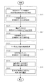
- FIG. 5 is a table showing an example of a relationship between an operation mode of the AV amplifier 13 and gain values of a plurality of channels of audio signals transferred by the AV amplifier 13. It is a flowchart which shows the process which selects a transfer system. It is a flowchart which shows the process which selects a transfer system.
- FIG. 1 shows an example of a network configuration of the AV system 10 of the present embodiment.
- a smartphone 11 a plurality of AV amplifiers 13 and 14, and a TV (television set) 17 are connected to a network 19.
- the network 19 is, for example, a home LAN (local network) that connects AV amplifiers 13 and 14 and a TV 17 installed in a plurality of rooms (a living room 21, a kitchen 22, and a study room 23) in one house. ⁇ Area network).
- the network 19 may be a wired network or a wireless network.
- the network 19 may be a wireless network compliant with Bluetooth (registered trademark) or a wireless network (wireless LAN) compliant with IEEE 802.11.
- the AV amplifiers 13 and 14 and the TV 17 perform communication based on a predetermined network protocol, and transmit and receive the packet P in which header information or the like is added to the acoustic signal via the network 19.
- the AV amplifiers 13 and 14 and the TV 17 connected to the network 19 may be collectively referred to as audio devices.
- a dedicated application for controlling the AV amplifier 13 is installed in the smartphone 11.
- a user U in the living room 21 controls the AV amplifier 13 while operating the smartphone 11.
- the smartphone 11 stores various contents such as music data, and functions as a source device of the AV system 10 of the present embodiment.
- the source device is not limited to the smartphone 11 and may be, for example, a CD player or a personal computer, or a network storage such as NAS (Network Attached Storage).
- the source device may be a music wiring server on the Internet.
- the file format of the music data may be MP3, WAV, SoundVQ (registered trademark), WMA (registered trademark), AAC, or the like, for example.
- the smartphone 11 can be connected to, for example, an AV amplifier 13 installed in the living room 21 via wireless communication.
- the user U operates the smartphone 11 to transmit the specified content, for example, 2.1ch music data D1 to the AV amplifier 13.
- a wireless communication standard used by the smartphone 11 for example, Bluetooth can be adopted.
- the smartphone 11 may communicate with the AV amplifier 13 via a router or the like connected to the network 19 by, for example, a Wi-Fi (registered trademark) wireless LAN.
- the AV amplifier 13 in the living room 21 has, for example, a 2.1ch speaker connection terminal.
- the analog connection cable 31 connected to this terminal is connected to a 2.1ch speaker 33 installed in the living room 21.
- the AV amplifier 13 reproduces the music data D1 received from the smartphone 11 from the speaker 33.
- the speaker connection terminal included in the AV amplifier 13 is not limited to the 2.1ch terminal, and may be, for example, a 5.1ch or 7.1ch terminal.
- the AV amplifier 13 performs processing for causing the TV 17 or the AV amplifier 14 to reproduce the same music data D1 received from the smartphone 11.
- the AV amplifier 13 performs signal processing for converting the 2.1ch music data D1 received from the smartphone 11 into music data D2 (for L channel) and music data D3 (for R channel) (see FIG. 3).
- the AV amplifier 13 can transfer the packet P including the converted music data D2 and D3 to the TV 17 and the AV amplifier 14.
- the converted music data D2 and D3 are data having the same number of channels (2.1 ch) as the music data D1. Details will be described later.
- the TV 17 installed in the kitchen 22 receives the packet P including the music data D2 and D3 from the AV amplifier 13 via the network 19.
- the TV 17 incorporates L (left) and R (right) stereo 2ch speakers 35.
- the TV 17 reproduces the music data D2 and D3 from the speaker 35.
- the AV amplifier 14 of the study 23 has, for example, a 2.1ch speaker connection terminal.
- the analog connection cable 37 connected to this terminal is connected to a 2.1ch speaker 39 installed in the study 23.
- the AV amplifier 14 receives the packet P including the music data D2 and D3 from the AV amplifier 13 via the network 19.
- the AV amplifier 14 reproduces the music data D2 and D3 from the speaker 39.
- the music data D2 and D3 described above are converted from the music data D1.
- the music data D ⁇ b> 1 is output from the 2.1ch speaker 33.
- the music data D2 and D3 are output as they are as stereo music from the 2-channel speaker 35 of the TV 17.
- the music data D1 is output from the 2.1ch speaker 39.
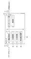
- FIG. 2 is a block diagram showing a configuration of the AV amplifier 13 in the living room 21, and shows only a part particularly related to the present invention.
- the AV amplifier 13 includes a signal processing unit 40, a wireless communication unit 41, an interface unit 47, and a control unit 48.
- the wireless communication unit 41 extracts music data D1 from data received from the smartphone 11 via wireless communication.
- a stereo L (left) channel acoustic signal and an R (right) channel acoustic signal include low-frequency dedicated (LFE (Low Frequency) Effect) channel acoustic signals.
- the added 2.1ch sound signal is included.
- the music data D1 does not include the low-frequency dedicated channel acoustic signal
- the low-frequency component generated based on the low-frequency component extracted from the L-channel acoustic signal and the R-channel acoustic signal is LFE. It may be an acoustic signal of a channel.
- the AV amplifier 13 of the present embodiment transfers an LFE channel acoustic signal (an example of additional information) in each of the 2ch acoustic signals.
- the signal processing unit 40 generates music data D2 and D3 by including the LFE channel acoustic signal in each of the L channel and R channel acoustic signals (hereinafter referred to as “signal generation processing”). There is).
- the music data D2 and D3 generated by the signal processing unit 40 are transmitted as a packet P from the interface unit 47 to the network 19.
- the signal processing unit 40 includes an AM (Amplitude Modulation) modulation unit 43, a Bit extension unit 44, and a frequency extension unit 45.
- the AM modulation unit 43 executes signal generation processing using an AM modulation method.
- the Bit extension unit 44 executes signal generation processing by the Bit extension method.
- the frequency extension unit 45 executes signal generation processing by a sampling frequency extension method.
- the AM modulation method, the Bit extension method, and the sampling frequency extension method may be collectively referred to as a “transfer method”.
- the transfer method is an example of a “signal generation processing method”.
- the control unit 48 is a device that performs overall control of the AV amplifier 13.
- the control unit 48 selects an execution subject of signal generation processing from the AM modulation unit 43, the bit expansion unit 44, and the frequency expansion unit 45.
- the control unit 48 selects one transfer method from the three types of transfer methods, that is, the AM modulation method, the bit extension method, and the sampling frequency extension method, and the signal is transmitted by the selected one transfer method. Run the generation process.
- the AM modulation unit 43, the Bit extension unit 44, and the frequency extension unit 45 can be realized by, for example, a sound processing DSP (Digital Signal Processor) executing a predetermined program. Further, the AM modulation unit 43, the Bit extension unit 44, and the frequency extension unit 45 may be realized by, for example, an analog circuit or may be realized by executing a program on the CPU.
- DSP Digital Signal Processor
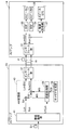
- FIG. 3 is a block diagram showing a connection relationship between the AV amplifier 13 in the living room 21 and the AV amplifier 14 in the study room 23, and only the part related to the AM modulation unit 43 is shown in the AV amplifier 13.
- the AM modulation unit 43 includes two adders 51 and 52, a modulation processing unit 55, and a carrier generation unit 56.
- the adder 51 corresponds to the L channel. That is, the L channel acoustic signal among the acoustic signals extracted from the music data D1 by the wireless communication unit 41 is input to the adder 51.
- the adder 52 corresponds to the R channel.
- the R channel acoustic signal among the acoustic signals extracted from the music data D1 by the wireless communication unit 41 is input to the adder 52.
- an acoustic signal of the LFE channel is input from the wireless communication unit 41 to the modulation processing unit 55.
- the acoustic signals of the L channel, the R channel, and the LFE channel are acoustic signals sampled at 48 kHz, for example.
- the modulation processing unit 55 downsamples the acoustic signal of the LFE channel.
- the carrier generation unit 56 outputs the carrier signal CS to the modulation processing unit 55.
- the modulation processing unit 55 performs AM modulation on the carrier signal CS input from the carrier generation unit 56 using the sample value of the down-sampled LFE channel acoustic signal, and a modulated signal (hereinafter referred to as “modulation signal MS”). Is output to the adders 51 and 52.
- the carrier generation unit 56 outputs a signal in a frequency band that is difficult to be heard by human ears as the carrier signal CS.
- a 2ch audio device for example, the TV 17
- multichannel (2.1ch) playback does not feel uncomfortable as 2ch music data even if the received music data D2 and D3 are played back as they are. Stereo sound can be reproduced with sound.
- an LFE channel acoustic signal sampled at a sampling frequency of 48 kHz is down-sampled by 1/8.
- the carrier signal CS a signal in a band that is difficult to be heard by the human ear is used as the carrier signal CS.
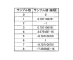
- FIG. 4A shows sample values of eight samples sampled from three periods of a 18 kHz sine wave having an amplitude of “1” (ie, eight samples included in one period of the carrier signal CS). Each value).
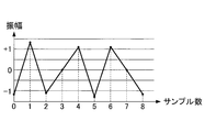
- FIG. 4B shows a waveform for one cycle of the carrier signal CS. In the following, the sample value may be referred to as a sample amplitude value.
- the carrier generation unit 56 outputs the carrier signal CS shown in FIG. 4B to the modulation processing unit 55.
- the modulation processing unit 55 performs AM modulation on the carrier signal CS input from the carrier generation unit 56 by using a sample value (volume level) obtained by down-sampling the acoustic signal of the LFE channel input from the wireless communication unit 41 by 1/8. Output to the adders 51 and 52. Since this signal is an acoustic signal of 18 kHz, even if it is reproduced as it is on the reproduction side, it becomes a sound that is extremely difficult to hear by human ears.
- the adder 51 adds the modulation signal MS output from the modulation processing unit 55 to the L channel acoustic signal sampled at 48 kHz, and interfaces as an L channel acoustic signal (music data D2).
- the adder 52 adds the modulation signal MS output from the modulation processing unit 55 to the R channel acoustic signal sampled at 48 kHz, and outputs the result to the interface unit 47 as an R channel acoustic signal (music data D3).
- the interface unit 47 packetizes the L-channel music data D2 input from the adder 51 and the R-channel music data D3 input from the adder 52, and packetizes the AV amplifier 14 via the network 19 as a packet P. Forward to.
- the interface unit 61 of the AV amplifier 14 receives the packet P from the interface unit 47 of the AV amplifier 13.
- the interface unit 61 extracts music data D2 corresponding to the L channel and music data D3 corresponding to the R channel from the received packet P.
- the interface unit 61 outputs the music data D2 corresponding to the L channel to a BEF (Band Elimination Filter) 63.
- the BEF 63 is a filter that allows passage of music data D2 corresponding to the L channel other than a signal in a predetermined frequency band.
- the BEF 63 outputs, to the speaker 39 corresponding to the L channel, an acoustic signal from which the 18 kHz AM modulation component unnecessary for the L channel is removed from the music data D2.
- the interface unit 61 outputs music data D3 corresponding to the R channel to the BEF 64.
- the BEF 64 is a filter that allows passage of music data D3 corresponding to the R channel other than signals in a predetermined frequency band.
- the BEF 64 outputs to the speaker 39 corresponding to the R channel an acoustic signal obtained by removing the 18 kHz AM modulation component unnecessary for the R channel from the music data D3.
- the interface unit 61 outputs the music data D2 corresponding to the L channel and the music data D3 corresponding to the R channel to the demodulation processing unit 67.
- the demodulation processing unit 67 downsamples the acoustic signals included in the input music data D2 and D3 by 1/8 and multiplies the 1/8 downsampled signal by a sine wave of 18 kHz.
- the demodulation processing unit 67 firstly down-samples the acoustic signals included in the music data D2 and D3 input to the demodulation processing unit 67 by 1/8, whereby a plurality of modulation signals MS have Take a sample value.
- the demodulation processing unit 67 extracts the amplitude value of the demodulation signal MD by multiplying the extracted modulation signal MS by a sine wave of 18 kHz.
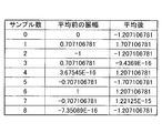
- FIG. 5 shows, as an example, assuming that the amplitude value of the modulation signal MS is “1.0”, 8 sample values (amplitude before multiplication) included in one period of the modulation signal MS, and 8 included in the modulation signal MS.
- 8 shows eight sample values (amplitude after multiplication) of the demodulated signal MD obtained by multiplying each sample value by a sine wave of 18 kHz.
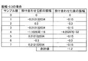
- FIG. 6 shows, as an example, the amplitude value of the modulation signal MS is set to “ ⁇ 0.3”, eight sample values (amplitude before multiplication) included in one period of the modulation signal MS, and the modulation signal MS.
- 8 shows eight sample values (amplitude after multiplication) of the demodulated signal MD obtained by multiplying eight sample values by a sine wave of 18 kHz. As shown in FIG.
- the total value “4” of the eight sample values included in one cycle of the demodulated signal MD is four times the amplitude value “1” of the modulation signal MS.
- the total value “ ⁇ 1.2” of the eight sample values included in one period of the demodulated signal MD is four times the amplitude value “ ⁇ 0.3” of the modulation signal MS. It has become. That is, the total value of the eight sample values included in one cycle of the demodulated signal MD is four times the amplitude value of the modulation signal MS. Therefore, the amplitude value of the modulation signal MS can be extracted by multiplying the total value of the eight sample values included in one period of the demodulation signal MD by 1/4.
- the demodulation processing unit 67 includes a plurality of demodulated signals MD so that the amplitude of the demodulated signal MD is 1 ⁇ 4 times the sum of the eight sample values of one period of the demodulated signal MD.
- the LFE channel acoustic signal is demodulated by correcting the sample value and up-sampling the demodulated signal MD after the correction by 8 times.
- 5 and 6 illustrate the case where the modulation signal MS and the carrier signal CS have the same waveform for convenience of explanation.
- the following two problems can be considered in the AM modulation system described above.
- a signal (modulated signal MS) obtained by AM-modulating the 18 kHz band signal originally included in the L-channel acoustic signal and the R-channel acoustic signal as a noise component. Therefore, it is necessary for the demodulation processing unit 67 to extract only the modulation signal MS so as not to be affected by the original L channel acoustic signal or the original R channel acoustic signal as much as possible.
- the adder 51 and the adder 52 superimpose the modulation signal MS on the L-channel acoustic signal and the R-channel acoustic signal.
- the demodulation processing unit 67 it is difficult for the demodulation processing unit 67 to detect the start position of the period of the modulation signal MS. That is, in the demodulation processing unit 67, the reference sample value (for example, the first sample value in the period of the modulation signal MS) among the plurality of sample values of the modulation signal MS and the 18 kHz sine wave reference Even if an attempt is made to multiply a plurality of sample values possessed by the modulation signal MS and a sine wave of 18 kHz after aligning the positions (for example, the position where the phase is “0”), it becomes a reference possessed by the modulation signal MS. It may be difficult to detect the sample value.
- the reference sample value for example, the first sample value in the period of the modulation signal MS
- the demodulation processing unit 67 there is a possibility that a plurality of sample values of the modulation signal MS and the 18 kHz sine wave may be multiplied without matching the reference, and the acoustic signal of the LFE channel cannot be accurately demodulated. There is a fear.
- the AM modulation unit 43 of the AV amplifier 13 that is the transfer source adds the modulation signal MS to the L-channel acoustic signal and the R-channel acoustic signal according to the following rules.
- a general music signal is likely to contain many in-phase components such as a vocal component as signal components of the L channel and the R channel.
- This in-phase component can be removed, for example, by subtracting the R channel acoustic signal from the L channel acoustic signal (Lch-Rch). Therefore, for example, the adder 51 adds the modulation signal MS to the L channel acoustic signal as an in-phase component.
- the adder 52 adds the modulation signal MS to the R channel acoustic signal as an antiphase component.
- the in-phase component included in the L-channel acoustic signal and the R-channel acoustic signal is “C” and the modulation signal MS component is “D”
- the demodulation processing unit 67 of the AV amplifier 14 that is the transfer destination subtracts the R channel acoustic signal from the L channel acoustic signal (Lch-Rch) as represented by the following equation (1).
- the demodulation processing unit 67 can remove the in-phase component C and extract only “D” that is the modulation signal MS.
- the signal “2D” extracted in the expression (1) has twice the amplitude as compared with the original signal “D”, the noise ratio (S / N ratio) is increased to suppress the influence of noise. Is done.
- a general music signal may contain many low-frequency components and human voice band components (for example, 1 kHz). This low-frequency component or the like has a small waveform fluctuation for each sample. Therefore, the demodulation processing unit 67 at the transfer destination, for example, in each of the transferred music data D2 and D3, the samples before and after among the plurality of samples included in the music data D2 and D3 are represented by the following formulas. The original L channel and R channel signal components are removed by weighting so as to cancel each other and calculating the moving average value.
- the demodulation processing unit 67 converts each sample value of the monaural signal D extracted by the equation (1) according to the weighting conversion equation.
- FIG. 7A shows a plurality of sample values (amplitude before averaging) included in the modulation signal MS shown in FIG. 5 and sample values (after averaging) obtained by performing a moving average operation on the plurality of sample values. Shows the relationship.
- FIG. 7B shows a waveform of a signal after the above-described moving average calculation is performed on the modulation signal MS (hereinafter, also referred to as “average signal MA”).
- the demodulation processing unit 67 generates the average signal MA by performing the above-described moving average calculation on a plurality of sample values included in the modulation signal MS.
- the demodulation processing unit 67 extracts the demodulated signal MD by multiplying the averaged signal MA by a sine wave of 18 kHz.
- FIG. 8 shows, as an example, an averaged signal obtained by performing a moving average operation on a plurality of sample values of the modulation signal MS when the amplitude value of the modulation signal MS is “1.0”.
- Eight sample values of the demodulated signal MD obtained by multiplying the eight sample values of MA (amplitude before multiplication) and the eight sample values of the post-average signal MA by an 18 kHz sine wave (Amplitude after multiplication).
- FIG. 9 shows, as an example, after averaging, obtained by performing a moving average operation on a plurality of sample values of the modulation signal MS when the amplitude value of the modulation signal MS is “ ⁇ 0.3”.
- Eight samples of the demodulated signal MD obtained by multiplying the eight sample values of the signal MA (amplitude before multiplication) and the eight sample values of the signal MA after averaging by a sine wave of 18 kHz. Value (amplitude after multiplication).
- the total value “11.56585425” of the eight sample values that are the sample values for one period included in the demodulated signal MD is approximately 11.1 of the amplitude value “1.0” of the modulation signal MS. 6 times.
- the total value “ ⁇ 3.497056275” of eight sample values that are the sample values for one period included in the demodulated signal MD is the amplitude value “ ⁇ 0.3” of the modulation signal MS. About 11.6 times.
- the demodulation processing unit 67 is configured so that the amplitude of the demodulated signal MD is “1 / 11.6585425” times the total value of the sample values for one period included in the demodulated signal MD.
- the LFE channel acoustic signal is demodulated by correcting a plurality of sample values of the demodulated signal MD and up-sampling the demodulated signal MD after the correction by 8 times.
- the demodulation processing unit 67 removes the components of the L channel and R channel acoustic signals from the music data D2 and D3, and the original signals (L channel acoustic signals and R channel acoustic signals) are obtained.
- the influence on the modulation signal MS as a noise component is reduced to solve the first problem.
- the demodulation processing unit 67 first determines a provisional start position that is a provisional sample start position from among a plurality of samples included in the averaged signal MA.
- the demodulation processing unit 67 sets the provisional start position as the first sample position, and the range from the first sample position to the eighth sample position (that is, a range corresponding to one cycle of the averaged signal MA), Set as provisional sample range.
- the demodulation processing unit 67 aligns the provisional start position and the reference position of the 18 kHz sine wave, and then adds the 18 kHz sine to each sample value of the eight samples of the averaged signal MA in the provisional sample range. By multiplying the waves, the sample values of each of the eight samples of the demodulated signal MD in the provisional sample range are calculated.
- the demodulation processing unit 67 sums the eight sample values of the demodulated signal MD in the provisional sample range.
- the demodulation processing unit 67 repeats the process for calculating the total value of the eight sample values of the demodulated signal MD in the provisional sample range described above, for example, eight times while changing the provisional start position one by one. Then, the demodulation processing unit 67 determines the provisional start position where the absolute value of the total value of the eight sample values of the demodulated signal MD in the provisional sample range is the largest as the sample start position (the sample position corresponding to the reference sample value). ).
- FIG. 10 shows, for each of the cases where the provisional start position is changed from “0” to “6”, the eight sample values of the demodulated signal MD in the provisional sample range and the total value of the eight sample values.
- FIG. 10 as in FIG. 8, the case where the amplitude value of the modulation signal MS is “1.0” is assumed as an example. Further, in FIG. 10, it is assumed as an example that the sample position “0” is a reference position of an 18 kHz sine wave (for example, a start position of an 18 kHz sine wave waveform). As shown in FIG.
- the demodulated signal MD in the temporary sample range is the maximum value (11.6655854).
- the temporary sample range is “1 to 8” and the temporary start position “1” is different from “0” which is the reference position of the 18 kHz sine wave, the eight demodulated signals MD in the temporary sample range
- the absolute value of the total value of the sample values is a smaller value (8.2426406687) than the maximum value (11.65685425).
- the demodulation processing unit 67 sets the temporary start position where the absolute value of the total value of the eight sample values of the demodulated signal MD in the temporary sample range is the largest as the sample start position, thereby allowing the music data D2 and It is possible to appropriately set the position where the sine wave is multiplied to D3 or the signal D that has been made monaural.
- the absolute value of the total value of the eight sample values of the demodulated signal MD in the provisional sample range is the maximum value (11.65685425). It becomes.
- the LFE signal that is the object of AM modulation is a low-frequency component and the difference for each sample is small, the sign is set regardless of which sample position “0” or sample position “4” is set as the start position.
- the error as a signal after multiplying waves is small. For example, if the original signal before AM modulation is set to a positive value in advance, the maximum positive value can be detected as the start position.
- the transfer source modulation processing unit 55 performs “(sample value) * 0.5 + 0” for the carrier signal CS whose sample value is in the range of “ ⁇ 1.0 to +1.0”. .5 ", the entire waveform of the carrier signal CS is set to a positive value.
- a provisional start position where the maximum value of the total value of the eight sample values of the demodulation signal MD in the provisional sample range is positive is set as the sample start position, and each sample included in the demodulation signal MD is set.
- An LFE channel signal can be extracted by calculating “(sample value ⁇ 0.5) * 2.0” and inversely converting the value.
- the modulation processing unit 55 performs AM modulation on the carrier signal CS generated based on the 18 kHz sine wave is described, but the present invention is not limited thereto.
- the modulation processing unit 55 may AM modulate the LFE channel acoustic signal using the carrier signal CS in a frequency band higher than the audible band, and add the result to the L channel acoustic signal and the R channel acoustic signal.
- the carrier signal CS is AM-modulated by the LFE channel acoustic signal that is 1/8 down-sampled. can do.
- the music data D1 does not include a high frequency component such as 192 kHz, the signal included in the music data D1 does not affect the noise.
- the bit extension unit 44 mixes and transfers a plurality of channel signals using an empty area of the quantization bit of the acoustic signal.
- music content on a CD Compact Disc
- a value of “0” is set to the minimum 8 bits. Therefore, the bit extension unit 44 uses a minimum of 8 bits to extend each of the L-channel acoustic signal and the R-channel acoustic signal quantized with 16 bits to 24 bits.
- the sound signal of the channel is transferred. This minimum 8 bits is relatively small in volume (sound pressure level). Therefore, even if an audio signal of another channel is set and reproduced with 24 bits, it becomes a volume region that is hard to be heard by human ears, and it is possible to reproduce a sound with a little uncomfortable feeling at the transfer destination.
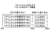
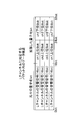
- FIG. 11 shows an example of the data structure of the packet P transferred on the network 19, and after the bit is expanded.
- the bit extension unit 44 uses 24 bits for each of the L channel acoustic signal and the R channel acoustic signal quantized with 16 bits among the acoustic signals extracted from the music data D1 by the wireless communication unit 41 (see FIG. 2). Perform extension processing so that it can be transferred.
- the bit extension unit 44 adds and transfers, for example, an acoustic signal of the LFE channel to a data area of at least 8 bits that increases by extending from 16 bits to 24 bits. Specifically, when the LFE channel acoustic signal is quantized with 16 bits, the Bit extension unit 44, as shown in FIG.
- the Bit extension unit 44 sets the lower 8 bits of the LFE channel acoustic signal in the extension region of the R channel acoustic signal and outputs the lower 8 bits to the interface unit 47 as music data D3.
- the interface unit 47 packetizes and transfers the music data D2 and D3 in the same packet P.
- the destination audio device performs processing according to the number of available channels.
- the bit values of the extended areas of the L-channel acoustic signal and the R-channel acoustic signal extracted from the packet P are cleared to zero and output to the speaker 35. That is, the audio device such as the TV 17 includes a “invalidation unit” that clears the bit value of the extension area of the acoustic signal to zero, and a “reproduction unit” that reproduces the invalidated signal.
- the TV 17 sets a dither signal (non-correlated noise) as the bit value of the extended area and outputs it to the speaker 35.
- the speaker 35 can reproduce the sound of the L channel and the R channel included in the music data D2 and D3. Moreover, even if the TV 17 is not compatible with the above-described invalidation processing of the extended area, the minimum 8-bit of 24 bits is a volume area that is hard to be heard by human ears as described above. However, it can be considered that the influence of noise is very small.
- the upper 8 bits and the lower 8 bits of the LFE channel acoustic signal are extracted from the packet P as a process of reproducing the acoustic signal of the LFE channel. Also, the AV amplifier 14 combines the upper 8 bits and the lower 8 bits of the extracted LFE channel acoustic signal, and generates an LFE channel acoustic signal that is a low-frequency acoustic signal quantized by 16 bits. The AV amplifier 14 outputs the generated LFE channel acoustic signal to the speaker 39.
- the audio equipment such as the AV amplifier 14 includes an “additional information acquisition unit” that extracts the upper 8 bits and the lower 8 bits of the acoustic signal of the LFE channel, and an “output unit” that outputs the extracted acoustic signal of the LFE channel. . Further, the AV amplifier 14 performs processing for reproducing the L-channel acoustic signal and the R-channel acoustic signal in the same manner as the TV 17, and extends each of the L-channel acoustic signal and the R-channel acoustic signal extracted from the packet P. Is cleared to zero and output to the speaker 39. In this Bit extension method, since the sound signals of a plurality of channels can be included in the same packet P, and the number of samples can be aligned and transferred in the same packet P, the sound output timing of each channel is aligned. It becomes easy.
- the Bit extension unit 44 can increase the above-described extension region (empty region) by increasing the sampling frequency, and mix other signals in the extension region, thereby simultaneously transferring more channels of acoustic signals and the like. It is possible. For example, a case will be described in which each of an L channel acoustic signal and an R channel acoustic signal sampled at 48 kHz is upsampled to 192 kHz.
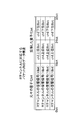
- FIG. 12A shows a state in which the up-sampled L-channel acoustic signal is expanded from 16 bits to 24 bits, and the acoustic signals of other channels are set in the expanded region.
- FIG. 12B shows a state in which the up-sampled R channel acoustic signal is expanded from 16 bits to 24 bits, and the acoustic signals of other channels are set in the expanded region.
- the data amount of the signal up-sampled to 192 kHz is four times that of the original 48 kHz signal. For this reason, the data area of the expanded quantization bit is also quadrupled.
- the acoustic signal of the other channel can be arranged every four samples. .
- four types of signals of other channels quantized with 16 bits can be set in the extension region.
- the upper and lower 8 bits of the acoustic signal of the other channel are present in the extension region of the first (first sample) L channel and R channel from the top. Is set.
- the upper and lower 8 bits of the sound signals of ch2, ch3, and ch4 are set in the second (second sample) and subsequent extended areas. In this case, it is possible to transfer a total of 6 channels obtained by adding 4 channels in the extension area to the original L channel and R channel (2 channels).
- a process for aligning sampling frequencies is required as a transfer destination process.
- the transfer destination AV amplifier 14 up-samples the CH1-CH4 channel acoustic signal in the expansion region from 48 kHz to 192 kHz, or the L channel acoustic signal and the R channel acoustic signal each from 192 kHz to 48 kHz. Downsampling makes the sampling frequency uniform.
- FIGS. 13A and 13B show the data structure of the packet P when the L-channel acoustic signal and the R-channel acoustic signal are expanded to 32 bits.
- a 16-bit data area (16-bit to 32-bit) can be secured in each of the expansion areas of the L-channel acoustic signal and the R-channel acoustic signal.
- both the upper and lower (16 bits) of the sound signal of ch1 other than the L channel and the R channel are set in the extension region of the first L channel from the top. .
- both the upper and lower (16 bits) of the ch2 acoustic signal are set in the extension region of the first R channel from the top.
- the Bit expansion unit 44 can expand the number of bits and increase the number of channels that can be set in the expansion region.
- the frequency extension unit 45 increases the sampling frequency to secure an empty area between data, and mixes and transfers a plurality of channel signals using the reserved empty area. For example, when the sampling frequency of each of the L-channel acoustic signal and the R-channel acoustic signal is 48 kHz, the frequency extension unit 45 increases the sampling frequency to 96 kHz, which is doubled. In the case of normal upsampling, a sample value obtained by newly sampling the original signal is set for the increased sample.
- the frequency extension unit 45 of the present embodiment maintains the 48 kHz data without re-sampling, and sets data different from the original acoustic signal in the increased sample portion. As a result, it is possible to mix another channel signal or the like with the L channel acoustic signal and the R channel acoustic signal.
- FIG. 14 shows data of each sample in the acoustic signal of the L channel before raising the sampling frequency (48 kHz) and after raising the sampling frequency (96 kHz).
- the frequency extension unit 45 increases the sampling frequency from 48 kHz to 96 kHz, which is doubled, and ensures “empty samples 1 to 4” between samples.
- the frequency extension unit 45 inserts data of other channels (such as LFE channel) different from the L channel and R channel into the empty samples 1 to 4, thereby transferring twice the number of channels as signal data. Is possible.
- FIG. 14 shows only the L channel acoustic signal, but the same number of channels can be transferred to the R channel acoustic signal by executing the same processing.
- the frequency extension unit 45 can transfer data for a total of four channels including the L channel and the R channel (2ch) plus two additional channels.
- the transfer destination AV amplifier 14 can acquire each channel individually by extracting data of different channels from the packet P every other sample.
- the sampling frequency is increased only during transfer. Further, the AV amplifier 14 only needs to return the sampling frequency from 96 kHz to the original 48 kHz with respect to the acquired data, and no re-sampling process is required, and the original 2.1ch music data D1 can be reproduced. . Also, in the sampling frequency expansion method, unlike the normal upsampling process, the data of a plurality of channels are exchanged for each sample and transferred. Therefore, in the sampling frequency expansion method, since the sound signals of a plurality of channels are transferred separately for each sample, it is possible to ensure a higher transfer rate and sound quality than the above-described AM modulation method and Bit expansion method. It becomes.
- the LFE sound signal is mixed with the L channel sound signal and the R channel sound signal and transferred.
- the data to be mixed is not limited to an acoustic signal, and metadata (text data, control data, etc.) may be used.
- the AV amplifier 13 may transfer control data for changing the gain as the control data to be mixed.
- a process for securing a head margin is required as a pre-process for executing a digital domain process in a DSP or the like.
- a process for returning the head margin is required as a pre-process for reproduction in the analog area.
- the AV amplifier 13 performs preprocessing for securing a head margin of ⁇ 10 dB in order to prevent a clip from occurring in the digital domain for an acoustic signal of a 0 dB full-scale LFE channel.
- the AV amplifier 13 transmits the head margin amount ( ⁇ 10 dB) previously attenuated in the digital domain as control data to the transfer destination audio device (for example, a subwoofer that reproduces only the LFE channel).
- the transfer destination subwoofer Based on the control data, the transfer destination subwoofer amplifies the LFE channel acoustic signal by +10 dB in the processing of the analog domain, so that the signal level of the LFE channel acoustic signal becomes the L channel acoustic signal and the R channel acoustic signal. It is possible to reproduce the signal with the same signal level. As a result, it is possible to avoid the occurrence of a clip in the processing in the digital domain and transfer it with higher sound quality.
- metadata such as control data can be transmitted in addition to the acoustic signals of a plurality of channels or in place of the acoustic signals of the plurality of channels.
- the AV amplifier 13 may mix and transfer control data related to gain adjustment of a specific channel according to the request of the user U, and change the reproduction state of the transfer destination.
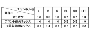
- FIG. 15 is an example of a table showing a relationship between a plurality of operation modes provided in the AV amplifier 13 and gain values of each of the multi-channel acoustic signals transferred by the AV amplifier 13.
- the AV amplifier 13 sets a gain value corresponding to each operation mode shown in FIG. 15 as control data, and transfers the mixed data in a 5.1ch multi-channel acoustic signal by each of the transfer methods described above.
- the transfer destination audio device for example, downmixes the received 5.1ch sound signal to 2ch and reproduces it.
- the transfer destination audio device realizes reproduction according to each operation mode by increasing / decreasing the signal level of each channel based on the gain value set in the control data.
- a gain value for each channel is set in the control data.
- the channel names L, C, R, SL, SR, and LFE in FIG. 15 indicate left (left), center, right (right), surround left, surround right, and low-frequency dedicated channels, respectively. Yes.
- the gain value “1.0 times (attenuation amount 0 dB)” is a signal level for reproducing normal music.
- the transfer destination audio device When the operation mode of the AV amplifier 13 is the karaoke mode, the transfer destination audio device performs mute “0 times (attenuation amount ⁇ dB)” and downmixes the center ch (Cch) containing a lot of vocal components. The voice of karaoke is reproduced by suppressing the voice of the vocal (see the bold part in FIG. 15).
- the surround channels SL and SR have a gain value of “0.7 times (attenuation amount ⁇ 3 dB)”. This is because the surround channels SL and SR need to be 0.7 times (attenuation amount ⁇ 3 dB) for level adjustment, for example, when 5.1ch is downmixed to 2ch.
- the transfer destination audio device downs the front side (Lch, Cch, and Rch) by “1.0 times (attenuation amount 0 dB)” as usual.
- the surround side (SLch and SRch) is reduced by “0.5 times (attenuation amount ⁇ 6 dB)” (refer to the bold portion in FIG. 15).
- the sound played from the destination audio device can be easily heard from the front side by suppressing the surround sound, which includes a lot of spectator voices, and emphasizing components such as vocal singing voices and player performance sounds. Sound.
- the transfer destination audio device When the operation mode of the AV amplifier 13 is the night trial listening mix mode, the transfer destination audio device lowers the Lch, Rch, and LFEch signal levels including a large volume signal and a lot of low-frequency components, The signal level of Cch containing a large amount of singing voice components is increased (see the bold portion in FIG. 15). For example, the transfer destination audio device multiplies the Lch and Rch signal levels by 0.7, multiplies the LFEch signal level by 0.3, and multiplies the Cch signal level by 1.4.
- the Cch signal level is increased to make it easier to hear the human voice and to suppress the low frequency component. It is possible to suppress vibrations and the like associated with music reproduction from causing inconveniences in the vicinity.
- the control unit 48 (see FIG. 2) of the AV amplifier 13 includes, for example, a data table in which gain values in the table shown in FIG. 15 are set in advance in a memory or the like, and performs each operation while referring to the data table.
- a signal level corresponding to the mode may be set as control data.
- the AV amplifier 13 may set a time stamp indicating the reproduction time of the music data D1 as metadata, and mix it with each of the L channel acoustic signal and the R channel acoustic signal. This makes it possible to align the sound output timings of the transfer source and the transfer destination.
- ⁇ Transfer of down-mixed sound signal> not only a normal 2ch sound signal but also a signal obtained by downmixing a conventionally used multi-channel to 2ch can be similarly transferred.
- the AV amplifier 13 can also mix and transfer the 5.1 channel signal to the L channel acoustic signal and the R channel acoustic signal downmixed to 2 channel by the above-described transfer methods.
- the destination audio device is a stereo speaker
- a downmixed 2ch sound signal can be reproduced.
- the transfer destination is a multi-channel speaker
- the down-mixed signal can be discarded and the multi-channel signal (5.1ch) included in the received signal can be separated and reproduced.
- the control unit 48 of the AV amplifier 13 (see FIG. 2), for example, “priority” when transferring the music data D1 to each audio device such as the AV amplifier 14 or the TV 17 and the transfer destination of the music data D1.
- An appropriate transfer method is selected based on the “processing performance” related to the music data D1 of the audio device. Note that the control unit 48 may select the transfer method based on either the priority or the processing performance.
- control unit 48 replaces one or both of the priority and the processing performance, or in addition to one or both of the priority and the processing performance, one of the number of channels of the music data D1 to be transferred and the content of the music data D1.
- the transfer method may be selected based on both.
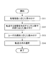
- the control unit 48 weights the transfer method according to the flowchart shown in FIG. 16 (see S11 to S13 in FIG. 16), and selects the transfer method based on the result. (Refer to S14 in FIG. 16).
- step S11 the control unit 48 weights the transfer method in accordance with the processing performance of the transfer destination audio device.
- step S11 the control unit 48 determines the processing performance of the transfer destination audio device. Regarding the determination of the processing performance, for example, the control unit 48 may determine based on the result of inquiring each audio device via the network 19 or may determine based on information input from the user U. Also good. Further, the control unit 48 may not directly inquire about the processing performance related to the music data D1.
- the control unit 48 may acquire only the performance information of the CPU of each audio device and estimate the processing performance related to the music data D1 based on the information.
- FIG. 17 is a diagram showing an example of a detailed flowchart of FIG.
- the control unit 48 first acquires information (an example of “performance information”) related to the processing performance of the audio device to which the music data D1 is transferred in step S11. Then, based on the acquired information, it is determined whether or not the audio device has a predetermined processing performance (S111). Next, in step S11, the control unit 48 sets values for the priorities W1 to W3 according to the determination result in step S111 (S112).
- the priority W1 is an evaluation value indicating the degree of appropriateness of using the AM modulation method for transferring the music data D1.
- the priority W2 is an evaluation value indicating the appropriateness of using the Bit expansion method for transferring the music data D1.
- the priority W3 is an evaluation value indicating the degree of appropriateness of using the sampling frequency expansion method for transferring the music data D1.
- an audio device having a predetermined processing performance is expressed as “the audio device has a high processing performance”, and an audio device does not have the predetermined processing performance. It may be expressed as “the processing performance of the device is low”.
- the processing performance of the audio device to which the music data D1 is transferred is low (for example, when the audio device is a single speaker device), in the audio device, for example, in the demodulation processing unit 67 (see FIG. 3). It is assumed that an executable channel separation process cannot be executed. If the transfer destination audio device cannot perform the channel separation process, the music data D1 transfer method to the transfer destination audio device is a sound that does not cause a sense of incompatibility even if it is reproduced without performing the channel separation process.
- the reproducible AM modulation method and Bit expansion method are effective. Therefore, when the control unit 48 determines that the processing performance of the transfer destination audio device is low, the control unit 48 increases the priority of the AM modulation method and the Bit expansion method.
- the control unit 48 sets a value w ⁇ b> 11 to the priority W ⁇ b> 1 related to the AM modulation scheme, and relates to the Bit expansion scheme
- the value w21 is set to the priority W2, and “0” is set to the priority W3 related to the sampling frequency expansion method (the value w11 is a real number satisfying 0 ⁇ w11.
- the value w21 is a real number satisfying 0 ⁇ w21) ).
- step S11 when the processing performance of the audio device to which the music data D1 is transferred is high, a sampling frequency expansion method that can maintain high-quality sound quality with the least data loss in the signal generation processing is effective as the transfer method. Become. Therefore, when the control unit 48 determines in step S11 that the processing performance of the transfer destination audio device is high, the control unit 48 increases the priority of the sampling frequency expansion method. Specifically, as illustrated in FIG. 17, when the result of the determination in step S111 is affirmative, the control unit 48 sets “0” to the priority W1 related to the AM modulation scheme, and sets the Bit expansion scheme.
- the priority W2 is set to “0”, and the value w31 is set to the priority W3 related to the sampling frequency expansion method (value w31 is a real number satisfying 0 ⁇ w31). Even when the transfer destination audio device has high performance, transfer using the AM modulation method or Bit extension method can be executed. Therefore, when the determination result in step S111 is affirmative, the value w11 is set to the priority W1 related to the AM modulation scheme, the value w21 is set to the priority W2 related to the Bit expansion scheme, and the sampling frequency extension The value w31 may be set for the priority W3 related to the method.
- step S12 the control unit 48 weights the transfer method according to one or both of the number of channels of the music data D1 to be transferred and the content of the music data D1.
- the control unit 48 can directly detect the number of channels of the music data D1 to be transferred, for example, or can detect based on the input information of the user U or the like.
- step S12 for example, when the music data D1 is music content in which a band-limited LFE channel is added to the basic front side 2ch, such as 2.1ch, or the music data D1 is In the case of music content in which a signal that is relatively unquestionable such as an announcement signal (email arrival notification) is added to 2ch of the above, since the high sound quality (sampling frequency) is not required, the control unit 48 For example, the priority of the AM modulation scheme is increased. For example, as illustrated in FIG. 17, the control unit 48 first determines in step S12 whether, for example, the music data D1 has a channel number equal to or greater than a predetermined channel number (for example, 3ch) (S121).
- a predetermined channel number for example, 3ch
- values are set for the priorities W1 to W3 according to the determination result in step S121 (S122). More specifically, when the result of the determination in step S121 is negative, the control unit 48 adds the value w12 to the priority W1 related to the AM modulation scheme and “0” to the priority W2 related to the Bit expansion scheme. Also, “0” is added to the priority W3 related to the sampling frequency expansion method (value w12 is a real number satisfying 0 ⁇ w12).
- the control unit 48 increases the priority of the Bit expansion method, for example.
- the control unit 48 performs sampling capable of high-quality transfer. Increase the priority of the frequency extension method. Specifically, as illustrated in FIG. 17, when the determination result in step S121 is affirmative, the control unit 48 adds “0” to the priority W1 related to the AM modulation method, and sets the Bit extension method.
- the value w22 is added to the priority W2 and the value w32 is added to the priority W3 related to the sampling frequency extension method (the value w22 is a real number satisfying 0 ⁇ w22.
- the value w32 is a real number satisfying 0 ⁇ w32) ).
- the control unit 48 can select the transfer method according to the number of channels of the music data D1 and the content of the signal (such as sound quality). Note that the priority setting described above is an example, and for example, 2.1ch or a sampling frequency expansion method may be used.
- step S ⁇ b> 13 the control unit 48 weights the transfer method according to the operation content (priority) of the user U with respect to the remote control of the AV amplifier 13 or the operation button provided on the AV amplifier 13.
- the user U operates a remote controller or the like to operate three items (instructions) of “reduction of power consumption at a transfer destination”, “reduction of delay between a plurality of channels”, and “priority of high-resolution sound quality”.
- One item can be selected.
- the control unit 48 first acquires the operation content by the user U (S131), and then acquires the operation content of the user U acquired in step S131. Accordingly, values are set for the priorities W1 to W3 (S132).
- the AM modulation method and the Bit extension method can reproduce the L channel sound signal and the R channel sound signal as they are, if it is desired to reduce power consumption, the channel in the transfer destination audio device is used.
- the power consumption necessary for the separation process can be suppressed by stopping the separation process and regenerating the separation process. For this reason, when the user U selects “reduction of power consumption at the transfer destination”, an AM modulation method or a Bit expansion method that enables selection of the presence or absence of separation processing according to the power consumption becomes effective. Therefore, the control unit 48 increases the priority of the AM modulation method and the Bit expansion method when “reduction of power consumption at the transfer destination” is selected. Specifically, as illustrated in FIG.
- the control unit 48 sets a value for the priority W ⁇ b> 1 related to the AM modulation method.
- w13 is added, the value w23 is added to the priority W2 related to the Bit expansion method, and “0” is added to the priority W3 related to the sampling frequency expansion method (value w13 is a real number satisfying 0 ⁇ w13).
- the value w23 is a real number satisfying 0 ⁇ w23).
- the control unit 48 increases the priority of the Bit expansion method when “reduction of delay between a plurality of channels” is selected by the user U. Specifically, as illustrated in FIG. 17, when the operation content acquired in step S131 is “reduction in delay between a plurality of channels”, the control unit 48 sets the priority W1 related to the AM modulation scheme to “ "0" is added, the value w23 is added to the priority W2 related to the Bit extension method, and "0" is added to the priority W3 related to the sampling frequency extension method.
- the control unit 48 increases the priority of the sampling frequency expansion method. Specifically, as illustrated in FIG. 17, when the operation content acquired in step S131 is “high-res sound quality priority”, the control unit 48 sets “0” to the priority W1 related to the AM modulation method. Then, “0” is added to the priority W2 related to the Bit expansion method, and the value w33 is added to the priority W3 related to the sampling frequency expansion method (value w33 is a real number satisfying 0 ⁇ w33). In the present embodiment, it is assumed that the values w11 to w33 added to the priorities W1 to W3 in steps S11 to S13 are equal to each other, for example, “1”.
- step S14 the control unit 48 selects a transfer method based on the results of the weighting performed in steps S11 to S13. Specifically, as illustrated in FIG. 17, in step S14, the control unit 48 first specifies the maximum priority W among the priorities W1 to W3 (S141). Next, the control unit 48 selects a transfer method corresponding to the maximum priority W specified in step S141 (S142). More specifically, in step S142, when the maximum priority W specified in step S141 is the priority W1, the control unit 48 selects the AM modulation method and specifies the maximum priority specified in step S141. When the degree W is the priority W2, the Bit extension method is selected, and when the maximum priority W specified in step S141 is the priority W3, the sampling frequency extension method is selected.
- the control unit 48 selects one of the plurality of transfer methods corresponding to the plurality of priorities W. For example, the transfer method may be selected at random. As described above, the control unit 48 can transfer the music data D1 by an appropriate method by selecting the transfer method from the three transfer methods according to the priority and the processing performance.
- the AV amplifier 13 is an example of a “signal processing device”.
- the AV amplifier 14 and the TV 17 are examples of a “playback device”.
- the interface unit 47 is an example of a “transfer unit”.
- the control unit 48 functions as a “selection unit” by executing part or all of steps S11 to S14.
- the control unit 48 functions as an “acquisition unit” by executing step S111.
- the music data D1 is an example of an “acoustic signal”.
- the music data D2 and D3 are examples of “transfer signals”.
- the acoustic signal and metadata of the LFE channel are examples of “additional information”.
- the interface unit 61 is an example of a “reception unit”.
- the demodulation processing unit 67 is an example of an “additional information acquisition unit”.
- the L channel acoustic signal is an example of a “first signal”.
- the R channel acoustic signal is an example of a “second signal”.
- the transfer destination audio device (for example, the TV 17) is a device that does not support the transfer method, and the L channel sound signal and the R channel sound signal mixed with the LFE channel sound signal are used. Even if it is reproduced as it is, it is possible to reproduce it with a sound that does not feel strange.
- the network 19 to which the AV system 10 is applied there is an audio device equipped with an abundant DSP such as an AV amplifier 14, while the received music data is simply played back like a speaker device alone. There is also.
- the transfer method described above does not require high processing performance from the transfer destination audio device, and it is possible to reproduce the original 2ch music only with simple processing. Therefore, it is possible to appropriately transfer data in which a plurality of signals are mixed within a limited audio band between audio devices having different generations, performances, purposes, solutions, and the like.
- the above three transfer methods are relatively easy to process compared to the downmix encoding process performed in the conventional signal generation process. However, it is possible to cope with this by a simple firmware update or the like.
- the values w11 to w33 added to the priorities W1 to W3 in steps S11 to S13 are equal to each other.
- the present invention is not limited to such a mode.
- some or all of the values w11 to w33 added to the priorities W1 to W3 may be different from each other.
- the importance levels of steps S11 to S13 may be determined in advance based on the operation of the user U, and the values w11 to w33 may be determined according to the importance levels.
- values added to the priorities W1 to W3 in each step w11 to w33 may be defined as “value added in step S11”> “value added in step S12”> “value added in step S13”.
- the control unit 48 selects the transfer method of the music data D1 for each audio device to which the music data D1 is transferred, but the present invention is not limited to such a mode. Absent. For example, when there are a plurality of audio devices to which the music data D1 is transferred, the control unit 48 sets the transfer method of the music data D1 so that the same transfer method is applied to the plurality of audio devices. You may choose. In this case, for example, in step S111, the control unit 48 may determine whether or not all of the plurality of audio devices that are the transfer destinations of the music data D1 have predetermined processing performance.
- control unit 48 may select the transfer method of the music data D1 so that the same transfer method is applied to all the audio devices connected to the network 19. In this case, for example, in step S111, the control unit 48 may determine whether all the audio devices connected to the network 19 have a predetermined processing performance.
- control unit 48 selects the transfer method of the music data D1 according to the processing performance of the audio device, but the present invention is not limited to such an aspect.
- control unit 48 selects the transfer method of the music data D1 in accordance with the processing performance of the network 19 such as the transfer rate of the network 19 instead of the processing performance of the audio device or in addition to the processing performance of the audio device. May be.
- control unit 48 executes steps S11 to S14 when selecting the transfer method of the music data D1, but the present invention is not limited to such a mode.
- control unit 48 may execute at least one of steps S11 to S13 and step S14.
- the AV amplifier and the TV are exemplified as the audio device, but the present invention is not limited to such an aspect.
- an audio device in addition to an AV amplifier and a TV, devices such as an AV receiver, a PC (personal computer), a smartphone, and an audio playback device can be employed.
- the low-frequency LFE channel acoustic signal is added as additional information to each of the L-channel acoustic signal and the R-channel acoustic signal.
- the additional information may be a signal other than the acoustic signal of the LFE channel, for example, a signal such as a warning sound.
- the additional information is added to each of the L-channel acoustic signal and the R-channel acoustic signal, but the present invention is not limited to such an aspect.
- the additional information may be added to an acoustic signal such as a surround left (SL) channel and a center (C) channel.
- the AV amplifier 13 may change the transfer method for each transfer destination audio device. For example, the AV amplifier 13 may perform transfer with the AV amplifier 14 and the Bit expansion method while transferring with the TV 17 by the AM modulation method.
- the signal processing device includes a transfer unit that transfers a transfer signal in which additional information is added to the acoustic signal toward the playback device, and generates the transfer signal by adding the additional information to the acoustic signal.
- a signal processing unit capable of executing the signal generation processing by a plurality of methods, and a selection unit that selects a signal generation processing method executed by the signal processing unit.
- an appropriate transfer method can be selected from a plurality of signal generation processing methods (transfer methods). For this reason, in a reproducing
- the signal processing device further includes an acquisition unit that acquires performance information that is information related to processing performance of the playback device in the signal processing device according to the first aspect, and the selection unit includes: A signal generation processing method executed by the signal processing unit is selected based on the performance information acquired by the acquisition unit. According to this aspect, it is possible to select a transfer method according to the processing performance of the playback device.
- the signal processing device is the signal processing device according to the first or second aspect, in which the selection unit performs signal generation processing executed by the signal processing unit based on the number of channels of the acoustic signal. The method is selected. According to this aspect, it is possible to select a transfer method according to the number of channels of the acoustic signal.
- a signal processing device is the signal processing device according to any one of the first to third aspects, characterized in that the additional information is a low-frequency channel signal.
- the signal of the low-frequency channel is composed of only the low-frequency component, even when the additional information is reproduced as it is, it can be reproduced with a sound without a sense of incongruity.
- the additional information is a signal of a channel different from the channel of the acoustic signal.
- signals of a plurality of channels can be transferred as transfer signals.
- a signal processing device is the signal processing device according to any one of the first to fifth aspects, wherein the signal processing unit is within a band that is difficult to be heard by a human ear within an audible band, or It is characterized by having an AM modulation unit for AM-modulating a carrier signal having a frequency in a non-audible band using additional information and adding the AM-modulated signal to an acoustic signal.
- the signal processing unit AM-modulates the additional information, adds it to the acoustic signal, and transfers it.
- the AM modulation unit is a carrier signal having a frequency that is difficult to be heard by the human ear (a carrier signal having a frequency in a band that is difficult to hear by the human ear) or a carrier signal having a frequency that cannot be heard by the human ear (in a non-audible band).
- the carrier signal of the frequency of the signal) is modulated using the additional information.
- the AM modulation method has a lighter processing load than the encoding process related to downmixing that has been performed in the conventional transfer process, and the time and amount of accumulation of the signal before the process in the reproduction apparatus at the transfer destination are conventionally reduced. Compared to the encoding process, the processing load can be reduced in terms of memory usage.
- a signal processing device is the signal processing device according to the sixth aspect, wherein the additional information is a low-frequency channel signal, and the AM modulation unit down-samples the low-frequency channel signal. And AM modulation.
- the AM modulation unit mixes and transfers the low-frequency channel signal to the acoustic signal. Since the low-frequency channel signal is composed of only the low-frequency component, it can be reproduced with a sound that does not feel strange even if the sampling frequency is lowered. Therefore, the AM modulation unit performs AM modulation using a sample value obtained by down-sampling the low-frequency signal, so that a plurality of acoustic signals can be combined and transferred to a limited acoustic channel band signal.
- the AM modulation unit A transfer signal is generated.
- the AM modulation method is selected as the transfer method even when the playback device does not have the predetermined processing performance and, for example, the demodulation process for separating the acoustic signal and the low frequency signal cannot be performed. Therefore, even if a signal obtained by mixing an acoustic signal and a low-frequency signal is reproduced as it is, it can be reproduced with a sound that does not feel strange.
- a signal processing device is the signal processing device according to any one of the first to eighth aspects, wherein the signal processing unit expands and expands the quantization bit of the acoustic signal. It is characterized by comprising a Bit extension unit for setting additional information in the reserved data extension area. According to this aspect, it is possible to transfer a combination of a plurality of pieces of information in a limited acoustic channel band signal.
- the bit expansion method for example, since a single packet transferred on the network can include acoustic signals of a plurality of channels and can be transferred by including the same number of samples in the same packet, It is easy to align the sound output timing.
- the bit extension unit upsamples the acoustic signal to increase the extension region. It is characterized by. According to this aspect, by increasing the sampling frequency and increasing the amount of data that can be secured as an extension area, it becomes possible to transfer more additional information at once.
- a signal processing device is the signal processing device according to any one of the first to tenth aspects, wherein the additional information is control data for adjusting a gain of the acoustic signal.
- the additional information is control data for adjusting a gain of the acoustic signal.
- a signal processing device is the signal processing device according to any one of the first to eleventh aspects, wherein the selection unit is operated by the user of the signal processing device and the processing of the playback device. Based on at least one of the performances, a signal generation processing method to be executed by the signal processing unit is selected. According to this aspect, a transfer method suitable for the user's operation content or the processing performance of the playback device can be selected from a plurality of transfer methods.
- the signal processing device is the signal processing device according to the twelfth aspect, wherein the operation content is an instruction to reduce power consumption related to processing of the transfer signal in the reproduction device, It is an instruction for reducing a delay in sound output based on the acoustic signal in the reproduction apparatus, or an instruction for improving sound quality when the acoustic signal is reproduced in the reproduction apparatus.
- a transfer method that can reduce power consumption in the playback device, reduce output delay in the playback device, or improve sound quality in the playback device is selected from a plurality of transfer methods. be able to.
- the acoustic signal transfer method includes a step of selecting a signal generation processing method for generating a transfer signal by adding additional information to an acoustic signal from a plurality of methods; And a step of generating a transfer signal and a step of transferring the generated transfer signal to a reproducing apparatus by the signal generation processing of the above-described method.
- an appropriate transfer method can be selected from a plurality of signal generation processing methods (transfer methods).
- a signal processing system is a signal processing system including a signal processing device and a reproduction device, and the signal processing device uses a transfer signal in which additional information is added to an acoustic signal as a reproduction device.
- a signal processing unit capable of executing a signal generation process for generating a transfer signal by adding additional information to an acoustic signal, and a signal generation process performed by the signal processing unit.
- a selection unit that selects a method. According to this aspect, when additional information is added to an acoustic signal for transfer, an appropriate transfer method can be selected from a plurality of signal generation processing methods (transfer methods).
- a transfer method includes an extension step of extending a quantization bit of an acoustic signal, a setting step of setting additional information in an extension area of data secured by the extension, and an acoustic signal And a transfer step of transferring a transfer signal with additional information added thereto.
- the additional information is transferred in the area where the quantization bit is expanded. This makes it possible to transfer a combination of a plurality of pieces of information in a limited acoustic channel band signal.
- an acoustic signal of a plurality of channels can be included in one packet transferred on the network, and the same number of samples can be included and transferred in the same packet. It is easy to align the sound output timing of each channel.
- the transfer method according to a seventeenth aspect of the present invention is the transfer method according to the sixteenth aspect, wherein the expansion step further includes an increase step of upsampling the acoustic signal to increase the expansion region.
- the expansion step further includes an increase step of upsampling the acoustic signal to increase the expansion region.
- a transfer method is the transfer method according to the sixteenth or seventeenth aspect, wherein the acoustic signal has a plurality of channels of the acoustic signal, and the setting step includes the additional information of the plurality of channels. It is characterized by being divided and set in an extended region corresponding to each acoustic signal. According to this aspect, for example, additional information (acoustic signal) for one channel can be divided and transferred to an extension area of a plurality of channels. As a result, even additional information that cannot be transferred in one extension area can be efficiently transferred by being divided into extension areas for each channel.
- a playback device is a playback device that plays back an acoustic signal transferred by the transfer method according to any of the sixteenth to eighteenth aspects, and adds additional information to the acoustic signal.
- An additional information acquisition unit that acquires additional information from a transfer signal and an output unit that outputs additional information acquired by the additional information acquisition unit. According to this aspect, it is possible to reproduce the acoustic signal while outputting the additional information included in the extended region obtained by extending the quantization bit.
- the additional information is another acoustic signal, it is possible to reproduce the acoustic signal transferred together and the additional information (other acoustic signal) together.
- a playback device is a playback device that plays back an acoustic signal transferred by the transfer method according to any of the sixteenth to eighteenth aspects, and adds additional information to the acoustic signal.
- an invalidation unit that invalidates the additional information
- a reproduction unit that reproduces the invalidated acoustic signal are provided.
- this aspect by invalidating the additional information in the extension area (zero clear, etc.), it is possible to reproduce only the acoustic signal even if the additional information in the extension area is not output (reproduction processing, etc.). It becomes.
- the transfer method includes an AM modulation step of AM-modulating a carrier signal having a frequency within a audible band that is difficult to be heard by a human ear or within a non-audible band using additional information; And adding an AM-modulated signal to the acoustic signal to generate a transfer signal, and a transfer step of transferring the transfer signal.
- the carrier signal is AM-modulated using the additional information, added to the acoustic signal, and transferred.
- a carrier signal having a frequency that is difficult or inaudible to human ears is modulated using the additional information.
- the AM modulation method has a lighter processing load than the encoding process related to downmixing performed in the conventional transfer process, and the time and amount of accumulation of the signal before the process in the transfer destination audio device can be reduced. Compared to the encoding process, the processing load can be reduced in terms of memory usage.
- the transfer method according to a twenty-second aspect of the present invention is the transfer method according to the twenty-first aspect, wherein the additional information is a low-frequency channel signal, and further includes a down-sampling step of down-sampling the low-frequency channel signal. It is characterized by having. Since the low-frequency channel signal is composed of only the low-frequency component, it can be reproduced with a sound that does not feel strange even if the sampling frequency is lowered. According to this aspect, by performing AM modulation using a sample value obtained by down-sampling a low-frequency channel signal, it is possible to transfer a plurality of acoustic signals in combination with a limited acoustic channel band signal. .
- a transfer method is the transfer method according to the twenty-first or twenty-second aspect, in which the acoustic signal includes a first signal and a second signal, and in the adding step, AM is added to the first signal. It has a difference calculation step of adding the modulated signal, adding the opposite phase component of the AM modulated signal to the second signal, and calculating the difference between the first signal and the second signal at the transfer destination. According to this aspect, the in-phase component of the first and second signals can be removed by calculating the difference between the first signal and the second signal at the transfer destination.
- an AM-modulated signal added in phase with the first signal and added in reverse phase with the second signal can be extracted as a signal having an amplitude twice that of the original signal by calculating the difference. It becomes possible to suppress the influence of noise by increasing the noise ratio (S / N ratio).
- the transfer method according to the twenty-fourth aspect of the present invention is the transfer method according to the twenty-third aspect, further comprising a moving average value calculating step for calculating a moving average value for the additional information extracted in the difference calculation step. It is characterized by. According to this aspect, by calculating the moving average value with respect to the additional information extracted by the difference calculation, it is possible to cancel out the component with little change for each sample from the acoustic signal included in the additional information. Become.
Landscapes
- Engineering & Computer Science (AREA)
- Physics & Mathematics (AREA)
- Acoustics & Sound (AREA)
- Signal Processing (AREA)
- Multimedia (AREA)
- Stereophonic System (AREA)
Abstract
信号処理装置は、音響信号に付加情報が付加された転送信号を再生装置に向けて転送する転送部と、音響信号に付加情報を付加して転送信号を生成する信号生成処理を、複数の方式により実行可能な信号処理部と、信号処理部が実行する信号生成処理の方式を選択する選択部と、を備える。
Description
本発明は、信号処理装置、音響信号の転送方法、及び、信号処理システムに関する。
従来、複数の音響信号を1つの伝送路で同時に送信するAVアンプ等のオーディオ機器の中には、例えば、映画などで使用されるマルチチャンネルの信号、具体的には5.1chの信号などをダウンミックスして2.1chの信号として転送するものがある(例えば、特許文献1など)。特許文献1に開示されるAVアンプは、ソース機器、TV、及びスピーカの各々に接続されている。ソース機器の音声をTV及びスピーカに同時に出力する場合、AVアンプは、例えば、自己の再生可能なチャンネル数をソース機器に通知し、ソース機器からチャンネル数に応じた音響信号を入力する。AVアンプは、再生可能なチャンネル数が少ないTVに対してはダウンミックスした音響信号を出力する。また、AVアンプは、再生可能なチャンネル数の多いスピーカに対しては音響信号のチャンネル数を変えずに出力する。
ところで、AVアンプ等のオーディオ機器は、ソース機器から入力された音響信号を再生装置に転送する際に、当該音響信号に付加情報を付加して転送する場合がある。この場合、音響信号をソース源から再生装置へ転送する転送方式によっては、再生装置において音響信号を適切に再生できないことがあった。
本願は、上記の事情を鑑み提案されたものであって、再生装置において、付加情報が付加された音響信号が適切に再生されない可能性を低減することを可能とする技術の提供を目的とする。
本願に係る信号処理装置は、音響信号に付加情報が付加された転送信号を再生装置に向けて転送する転送部と、前記音響信号に前記付加情報を付加して前記転送信号を生成する信号生成処理を、複数の方式により実行可能な信号処理部と、前記信号処理部が実行する前記信号生成処理の方式を選択する選択部と、を備えることを特徴とする。
本願に係る音響信号の転送方式は、音響信号に付加情報を付加して転送信号を生成する信号生成処理の方式を、複数の方式の中から選択するステップと、前記選択された方式の信号生成処理により、前記転送信号を生成するステップと、生成した前記転送信号を再生装置に向けて転送するステップと、を含む、ことを特徴とする。
本願に係る信号処理システムは、電子機器と再生装置とを含む信号処理システムであって、前記電子機器は、音響信号に付加情報が付加された転送信号を、前記再生装置に向けて転送する転送部と、前記音響信号に前記付加情報を付加して前記転送信号を生成する信号生成処理を、複数の方式により実行可能な信号処理部と、前記信号処理部が実行する前記信号生成処理の方式を選択する選択部と、を備え、前記再生装置は、前記転送信号を受信する受信部と、前記受信部の受信した前記転送信号から、前記付加情報を取得する付加情報取得部と、を備える、ことを特徴とする。
以下、本発明を具体化した一実施形態として、図1に示すAV(Audio Visual)システム10(「信号処理システム」の一例)について説明する。図1は、本実施形態のAVシステム10のネットワーク構成の一例を示している。AVシステム10は、スマートフォン11、複数のAVアンプ13及び14、並びにTV(television set)17がネットワーク19に接続されている。ネットワーク19は、例えば、1つの家の中の複数の部屋(リビング21、キッチン22、及び、書斎23)に設置された、AVアンプ13及び14並びにTV17を、相互に接続する家庭内LAN(ローカル・エリア・ネットワーク)である。なお、本実施形態では、ネットワーク19が家庭内LANである場合を例示して説明するが、本発明はこのような態様に限定されるものではない。ネットワーク19は、有線ネットワークであってもよいし、無線ネットワークであってもよい。例えば、ネットワーク19は、Bluetooth(登録商標)に準拠した無線ネットワークであってもよいし、IEEE 802.11に準拠した無線ネットワーク(無線LAN)であってもよい。AVアンプ13及び14並びにTV17は、例えば、所定のネットワークプロトコルに準拠した通信を実行し、ヘッダ情報等を音響信号に付加したパケットPを、ネットワーク19を介して送受信する。また、以下では、ネットワーク19に接続されるAVアンプ13及び14並びにTV17を、オーディオ機器と総称する場合がある。
スマートフォン11は、例えば、AVアンプ13を制御する専用のアプリケーションがインストールされている。リビング21にいるユーザUは、スマートフォン11を操作しながらAVアンプ13を制御する。また、スマートフォン11は、音楽データ等の様々なコンテンツが保存されており、本実施形態のAVシステム10のソース機器として機能する。なお、ソース機器は、スマートフォン11に限らず、例えば、CDプレーヤーやパーソナルコンピュータでもよく、あるいはNAS(Network Attached Storage)などのネットワークストレージでもよい。また、ソース機器は、インターネット上の音楽配線サーバでもよい。また、音楽データのファイル形式は、例えば、MP3、WAV、SoundVQ(登録商標)、WMA(登録商標)、または、AAC等でもよい。
また、スマートフォン11は、例えば、無線通信を介してリビング21に設置されたAVアンプ13と接続可能となっている。ユーザUは、スマートフォン11を操作して、指定したコンテンツ、例えば、2.1chの音楽データD1をAVアンプ13へ送信する。スマートフォン11が使用する無線通信の規格として、例えば、Bluetoothを採用することができる。また、スマートフォン11は、例えば、Wi-Fi(登録商標)規格の無線LANによって、ネットワーク19に接続されたルータ等を介してAVアンプ13と相互に通信してもよい。
リビング21のAVアンプ13は、例えば、2.1chのスピーカ接続用の端子を有している。この端子に接続されたアナログ接続ケーブル31は、リビング21に設置された2.1chのスピーカ33に接続されている。AVアンプ13は、スマートフォン11から受信した音楽データD1をスピーカ33から再生する。なお、AVアンプ13が備えるスピーカ接続用の端子は、2.1ch用の端子に限らず、例えば、5.1ch用、または、7.1ch用の端子でもよい。
また、AVアンプ13は、スマートフォン11から受信した同一の音楽データD1を、TV17またはAVアンプ14に再生させるための処理を行う。AVアンプ13は、スマートフォン11から受信した2.1chの音楽データD1を、音楽データD2(Lチャンネル用)及び音楽データD3(Rチャンネル用)に変換する信号処理を実施する(図3参照)。AVアンプ13は、変換後の音楽データD2及びD3を含むパケットPをTV17及びAVアンプ14に転送することができる。変換後の音楽データD2及びD3は、音楽データD1と同一のチャンネル数(2.1ch)をもつデータである。なお、詳細については後述する。
キッチン22に設置されたTV17は、AVアンプ13からネットワーク19を介して音楽データD2及びD3を含むパケットPを受信する。TV17は、L(左)及びR(右)のステレオ2chのスピーカ35を内蔵する。TV17は、スピーカ35から音楽データD2及びD3を再生する。
書斎23のAVアンプ14は、例えば、2.1chのスピーカ接続用の端子を有している。この端子に接続されたアナログ接続ケーブル37は、書斎23に設置された2.1chのスピーカ39に接続されている。AVアンプ14は、AVアンプ13からネットワーク19を介して音楽データD2及びD3を含むパケットPを受信する。AVアンプ14は、スピーカ39から音楽データD2及びD3を再生する。
上記した音楽データD2及びD3は、音楽データD1を変換したものである。本実施形態では、例えば、リビング21においては、音楽データD1を2.1chのスピーカ33から出力する。また、例えば、キッチン22では、音楽データD2及びD3をそのままTV17の2chのスピーカ35からステレオの音楽として出力する。また、例えば、書斎23においては、音楽データD1を2.1chのスピーカ39から出力する。
図2は、リビング21のAVアンプ13の構成を示すブロック図であり、本願発明に特に関係する部分のみを示している。図2に示すように、AVアンプ13は、信号処理部40、無線通信部41、インターフェース部47及び制御部48を有している。
無線通信部41は、スマートフォン11から無線通信を介して受信したデータから音楽データD1を取り出す。本実施形態の音楽データD1には、一例として、ステレオのL(左)チャンネルの音響信号及びR(右)チャンネルの音響信号に、低域専用(LFE(Low Frequency Effect))チャンネルの音響信号を加えた2.1chの音響信号が含まれている。なお、音楽データD1が低域専用チャンネルの音響信号を含まない場合には、Lチャンネルの音響信号及びRチャンネルの音響信号から低域成分を抜き出した音響信号に基づいて作り出した低域成分をLFEチャンネルの音響信号としてもよい。また、本実施形態のAVアンプ13は、一例として、2chの音響信号の各々の中に、LFEチャンネルの音響信号(付加情報の一例)を含めて転送する。
信号処理部40は、Lチャンネル及びRチャンネルの2チャンネルの音響信号の各々の中にLFEチャンネルの音響信号を含めて音楽データD2及びD3を生成する処理(以下、「信号生成処理」と称する場合がある)を実行する。信号処理部40によって生成された音楽データD2及びD3は、パケットPとしてインターフェース部47からネットワーク19へ送信される。
図2に示すように、本実施形態において、信号処理部40は、AM(Amplitude Modulation)変調部43、Bit拡張部44、及び、周波数拡張部45、を含む。AM変調部43は、AM変調方式による信号生成処理を実行する。Bit拡張部44は、Bit拡張方式による信号生成処理を実行する。周波数拡張部45は、サンプリング周波数拡張方式による信号生成処理を実行する。以下では、AM変調方式、Bit拡張方式、及び、サンプリング周波数拡張方式を、「転送方式」と総称する場合がある。すなわち、転送方式とは、「信号生成処理の方式」の一例である。
制御部48は、AVアンプ13を統括制御する装置である。制御部48は、AM変調部43、Bit拡張部44、及び、周波数拡張部45の中から、信号生成処理の実行主体を選択する。換言すれば、制御部48は、AM変調方式、Bit拡張方式、及び、サンプリング周波数拡張方式の3種類の転送方式の中から、一の転送方式を選択し、当該選択した一の転送方式により信号生成処理を実行させる。なお、AM変調部43、Bit拡張部44及び周波数拡張部45は、例えば、音響処理用のDSP(Digital Signal Processor)が所定のプログラムを実行することで実現できる。また、AM変調部43、Bit拡張部44及び周波数拡張部45を、例えば、アナログ回路で実現してもよく、あるいはCPU上でプログラムを実行することで実現してもよい。
図2に示すように、本実施形態において、信号処理部40は、AM(Amplitude Modulation)変調部43、Bit拡張部44、及び、周波数拡張部45、を含む。AM変調部43は、AM変調方式による信号生成処理を実行する。Bit拡張部44は、Bit拡張方式による信号生成処理を実行する。周波数拡張部45は、サンプリング周波数拡張方式による信号生成処理を実行する。以下では、AM変調方式、Bit拡張方式、及び、サンプリング周波数拡張方式を、「転送方式」と総称する場合がある。すなわち、転送方式とは、「信号生成処理の方式」の一例である。
制御部48は、AVアンプ13を統括制御する装置である。制御部48は、AM変調部43、Bit拡張部44、及び、周波数拡張部45の中から、信号生成処理の実行主体を選択する。換言すれば、制御部48は、AM変調方式、Bit拡張方式、及び、サンプリング周波数拡張方式の3種類の転送方式の中から、一の転送方式を選択し、当該選択した一の転送方式により信号生成処理を実行させる。なお、AM変調部43、Bit拡張部44及び周波数拡張部45は、例えば、音響処理用のDSP(Digital Signal Processor)が所定のプログラムを実行することで実現できる。また、AM変調部43、Bit拡張部44及び周波数拡張部45を、例えば、アナログ回路で実現してもよく、あるいはCPU上でプログラムを実行することで実現してもよい。
<AM変調方式について>
まず、AM変調部43によるAM変調方式について説明する。図3は、リビング21のAVアンプ13と、書斎23のAVアンプ14との接続関係を示すブロック図であり、AVアンプ13についてはAM変調部43に係わる部分のみを示している。図3に示すように、AM変調部43は、2つの加算器51及び52、変調処理部55、並びに、キャリア生成部56を有している。加算器51は、Lチャンネルに対応している。すなわち、加算器51には、無線通信部41が音楽データD1から取り出した音響信号のうち、Lチャンネルの音響信号が入力される。加算器52は、Rチャンネルに対応している。すなわち、加算器52には、無線通信部41が音楽データD1から取り出した音響信号のうち、Rチャンネルの音響信号が入力される。また、変調処理部55には、無線通信部41からLFEチャンネルの音響信号が入力される。Lチャンネル、Rチャンネル及びLFEチャンネルの音響信号は、例えば、48kHzでサンプリングされた音響信号である。
まず、AM変調部43によるAM変調方式について説明する。図3は、リビング21のAVアンプ13と、書斎23のAVアンプ14との接続関係を示すブロック図であり、AVアンプ13についてはAM変調部43に係わる部分のみを示している。図3に示すように、AM変調部43は、2つの加算器51及び52、変調処理部55、並びに、キャリア生成部56を有している。加算器51は、Lチャンネルに対応している。すなわち、加算器51には、無線通信部41が音楽データD1から取り出した音響信号のうち、Lチャンネルの音響信号が入力される。加算器52は、Rチャンネルに対応している。すなわち、加算器52には、無線通信部41が音楽データD1から取り出した音響信号のうち、Rチャンネルの音響信号が入力される。また、変調処理部55には、無線通信部41からLFEチャンネルの音響信号が入力される。Lチャンネル、Rチャンネル及びLFEチャンネルの音響信号は、例えば、48kHzでサンプリングされた音響信号である。
ここで、LFEチャンネルの音響信号は、低域成分のみで構成される信号であるため、サンプリング周波数を低くしても違和感のない音で再生することが可能となる。そこで、変調処理部55は、LFEチャンネルの音響信号をダウンサンプリングする。キャリア生成部56は、キャリア信号CSを変調処理部55に出力する。変調処理部55は、ダウンサンプリングしたLFEチャンネルの音響信号のサンプル値を用いてキャリア生成部56から入力されるキャリア信号CSに対しAM変調を実行し、変調後の信号(以下「変調信号MS」と称する場合がある)を加算器51及び52に出力する。
詳述すると、キャリア生成部56は、キャリア信号CSとして、人の耳には通常聞こえにくい周波数帯域の信号を出力する。これにより、マルチチャンネル(2.1ch)の再生に対応していない2chのオーディオ機器(例えば、TV17)は、受信した音楽データD2及びD3をそのまま再生したとしても、2chの音楽データとして違和感のない音でステレオ音声を再生することが可能となる。
一例として、48kHzのサンプリング周波数でサンプリングされたLFEチャンネルの音響信号を、1/8ダウンサンプリングする場合について説明する。本実施形態では、元の信号から1/8ダウンサンプリングする場合、AM変調に使用するデータとしては、元のデータが有する8サンプル毎に1個のデータが存在すればよい。従って、48kHzのサンプリング周波数により8個のサンプルを取得するために要する周期(以下、「8サンプル周期」と称する)が、1周期に相当する信号である、6kHz(=48kHz/8)の周波数の信号、及び、当該6kHzの整数倍の周波数を有する信号のうち、人の耳に聞こえにくい帯域の信号を、キャリア信号CSとして使用する。
キャリア信号CSの候補となる信号としては、以下が例示される。
・8サンプル周期が1周期となる信号:48kHz/8サンプル=6kHz
・8サンプル周期が2周期となる信号:(48kHz/8サンプル)*2=12kHz
・8サンプル周期が3周期となる信号:(48kHz/8サンプル)*3=18kHz
6kHz及び12kHzは、可聴帯域内であり、且つ再生時にノイズとなる可能性が高い。そこで、6kHzの整数倍の周波数を有する信号のうち、再生時に聞こえにくい周波数帯域として、例えば、18kHzの周波数を有する信号を、キャリア信号CSとして使用することができる。本実施形態では、18kHzのサイン波の3周期分からサンプリングされた8個のサンプルを1周期とする信号を、キャリア信号CSとする。
・8サンプル周期が1周期となる信号:48kHz/8サンプル=6kHz
・8サンプル周期が2周期となる信号:(48kHz/8サンプル)*2=12kHz
・8サンプル周期が3周期となる信号:(48kHz/8サンプル)*3=18kHz
6kHz及び12kHzは、可聴帯域内であり、且つ再生時にノイズとなる可能性が高い。そこで、6kHzの整数倍の周波数を有する信号のうち、再生時に聞こえにくい周波数帯域として、例えば、18kHzの周波数を有する信号を、キャリア信号CSとして使用することができる。本実施形態では、18kHzのサイン波の3周期分からサンプリングされた8個のサンプルを1周期とする信号を、キャリア信号CSとする。
図4Aは、振幅の大きさが「1」となる18kHzのサイン波の3周期分からサンプリングされた8個のサンプルの各々のサンプル値(すなわち、キャリア信号CSの1周期が有する8個のサンプルの各々の値)を示している。また、図4Bは、キャリア信号CSの1周期分の波形を示している。なお、以下では、サンプル値のことを、サンプルの振幅値と称する場合がある。キャリア生成部56は、図4Bに示すキャリア信号CSを変調処理部55に出力する。変調処理部55は、無線通信部41から入力されたLFEチャンネルの音響信号を1/8ダウンサンプリングしたサンプル値(音量レベル)を用いて、キャリア生成部56から入力されたキャリア信号CSをAM変調し、加算器51及び52に出力する。この信号は、18kHzの音響信号となるため、仮に、再生側でそのまま再生したとしても人の耳には極めて聞こえにくい音声となる。
図3に示すように、加算器51は、変調処理部55が出力した変調信号MSを、48kHzでサンプリングされたLチャンネルの音響信号に加算し、Lチャンネルの音響信号(音楽データD2)としてインターフェース部47に出力する。同様に、加算器52は、変調処理部55が出力した変調信号MSを、48kHzでサンプリングされたRチャンネルの音響信号に加算し、Rチャンネルの音響信号(音楽データD3)としてインターフェース部47に出力する。インターフェース部47は、加算器51から入力されたLチャンネルの音楽データD2と、加算器52から入力されたRチャンネルの音楽データD3と、をパケット化し、パケットPとしてネットワーク19を介してAVアンプ14へ転送する。
AVアンプ14のインターフェース部61は、AVアンプ13のインターフェース部47からパケットPを受信する。インターフェース部61は、受信したパケットPからLチャンネルに対応する音楽データD2と、Rチャンネルに対応する音楽データD3を取り出す。インターフェース部61は、Lチャンネルに対応する音楽データD2をBEF(バンドエリミネーションフィルタ(Band Elimination Filter))63に出力する。BEF63は、Lチャンネルに対応する音楽データD2のうち、所定周波数帯域の信号以外を通過させるフィルタである。BEF63は、音楽データD2から、Lチャンネルとして不要な18kHzのAM変調成分などを除去した音響信号を、Lチャンネルに対応するスピーカ39へ出力する。
同様に、インターフェース部61は、Rチャンネルに対応する音楽データD3をBEF64に出力する。BEF64は、Rチャンネルに対応する音楽データD3のうち、所定周波数帯域の信号以外を通過させるフィルタである。BEF64は、音楽データD3から、Rチャンネルとして不要な18kHzのAM変調成分などを除去した音響信号を、Rチャンネルに対応するスピーカ39へ出力する。
また、インターフェース部61は、Lチャンネルに対応する音楽データD2と、Rチャンネルに対応する音楽データD3と、を復調処理部67に出力する。復調処理部67は、例えば、入力した音楽データD2及びD3に含まれる音響信号を1/8ダウンサンプリングし、当該1/8ダウンサンプリングされた信号に対して18kHzのサイン波を掛け合わせる。具体的には、復調処理部67は、第1に、復調処理部67に入力された音楽データD2及びD3に含まれる音響信号を1/8ダウンサンプリングすることで、変調信号MSが有する複数のサンプル値を取り出す。復調処理部67は、第2に、取り出した変調信号MSに18kHzのサイン波を掛け合わせることで、復調信号MDの振幅値を取り出す。
図5は、一例として、変調信号MSの振幅値を「1.0」として、変調信号MSの1周期が有する8個のサンプル値(掛け合わせる前の振幅)と、当該変調信号MSが有する8個のサンプル値に18kHzのサイン波に掛け合わせることで得られる復調信号MDの8個のサンプル値(掛け合わせた後の振幅)と、を示している。図6は、一例として、変調信号MSの振幅値を「-0.3」として、変調信号MSの1周期が有する8個のサンプル値(掛け合わせる前の振幅)と、当該変調信号MSが有する8個のサンプル値に18kHzのサイン波に掛け合わせることで得られる復調信号MDの8個のサンプル値(掛け合わせた後の振幅)と、を示している。図5に示すように、復調信号MDの1周期が有する8個のサンプル値の合計値「4」は、変調信号MSの振幅値「1」の4倍となっている。同様に、図6に示すように、復調信号MDの1周期が有する8個のサンプル値の合計値「-1.2」は、変調信号MSの振幅値「-0.3」の4倍となっている。すなわち、復調信号MDの1周期が有する8個のサンプル値の合計値が、変調信号MSの振幅値の4倍になっている。このため、変調信号MSの振幅値は、復調信号MDの1周期が有する8個のサンプル値の合計値を1/4倍することで取り出すことができる。そこで、復調処理部67は、復調信号MDの振幅が、復調信号MDの1周期が有する8個のサンプル値の合計値の1/4倍の振幅となるように、復調信号MDが有する複数のサンプル値を補正し、当該補正後の復調信号MDを8倍アップサンプリングすることで、LFEチャンネルの音響信号を復調する。なお、図5及び図6では、説明の便宜上、変調信号MSとキャリア信号CSとが同一の波形を有する場合を例示して説明している。
ここで、上記したAM変調方式では、次の2つの問題が考えられる。
第1に、Lチャンネルの音響信号及びRチャンネルの音響信号に元々含まれている18kHz帯の信号がノイズ成分としてAM変調した信号(変調信号MS)に影響を与える虞がある。このため、復調処理部67は、可能な限り、元のLチャンネルの音響信号または元のRチャンネルの音響信号の影響を受けないように、変調信号MSのみを取り出す必要がある。
第2に、加算器51及び加算器52は、変調信号MSを、Lチャンネルの音響信号及びRチャンネルの音響信号に重畳させる。このため、復調処理部67において、変調信号MSの周期の開始位置を検出することが困難となる。すなわち、復調処理部67において、変調信号MSが有する複数のサンプル値のうち基準となるサンプル値(例えば、変調信号MSが有する周期の中で、最初のサンプル値)と、18kHzのサイン波の基準位置(例えば、位相が「0」となる位置)とを揃えた上で、変調信号MSが有する複数のサンプル値と18kHzのサイン波とを掛け合わせようとしても、変調信号MSが有する基準となるサンプル値の検出が困難となる場合がある。このため、復調処理部67において、変調信号MSが有する複数のサンプル値と18kHzのサイン波とを、基準を揃えることなく掛け合わせてしまう可能性が生じ、LFEチャンネルの音響信号を精度良く復調できない虞がある。
第1に、Lチャンネルの音響信号及びRチャンネルの音響信号に元々含まれている18kHz帯の信号がノイズ成分としてAM変調した信号(変調信号MS)に影響を与える虞がある。このため、復調処理部67は、可能な限り、元のLチャンネルの音響信号または元のRチャンネルの音響信号の影響を受けないように、変調信号MSのみを取り出す必要がある。
第2に、加算器51及び加算器52は、変調信号MSを、Lチャンネルの音響信号及びRチャンネルの音響信号に重畳させる。このため、復調処理部67において、変調信号MSの周期の開始位置を検出することが困難となる。すなわち、復調処理部67において、変調信号MSが有する複数のサンプル値のうち基準となるサンプル値(例えば、変調信号MSが有する周期の中で、最初のサンプル値)と、18kHzのサイン波の基準位置(例えば、位相が「0」となる位置)とを揃えた上で、変調信号MSが有する複数のサンプル値と18kHzのサイン波とを掛け合わせようとしても、変調信号MSが有する基準となるサンプル値の検出が困難となる場合がある。このため、復調処理部67において、変調信号MSが有する複数のサンプル値と18kHzのサイン波とを、基準を揃えることなく掛け合わせてしまう可能性が生じ、LFEチャンネルの音響信号を精度良く復調できない虞がある。
<同相成分の除去について>
そこで、転送元であるAVアンプ13のAM変調部43は、変調信号MSを、下記のルールに従ってLチャンネルの音響信号及びRチャンネルの音響信号に加算する。一般的な音楽信号では、Lチャンネル及びRチャンネルの信号成分として、ボーカル成分などの同相成分が多く含まれている可能性が高い。この同相成分は、例えば、Lチャンネルの音響信号からRチャンネルの音響信号を減算(Lch-Rch)することで除去できる。そこで、例えば、加算器51は、変調信号MSを、同相成分としてLチャンネルの音響信号に加算する。また、加算器52は、変調信号MSを、逆相成分としてRチャンネルの音響信号に加算する。Lチャンネルの音響信号及びRチャンネルの音響信号に多く含まれる同相成分を「C」、変調信号MSの成分を「D」とした場合、変調信号MSを加算後のLチャンネルの音響信号及びRチャンネルの音響信号は、下記の式で表される。
Lch=C+D
Rch=C-D
そこで、転送元であるAVアンプ13のAM変調部43は、変調信号MSを、下記のルールに従ってLチャンネルの音響信号及びRチャンネルの音響信号に加算する。一般的な音楽信号では、Lチャンネル及びRチャンネルの信号成分として、ボーカル成分などの同相成分が多く含まれている可能性が高い。この同相成分は、例えば、Lチャンネルの音響信号からRチャンネルの音響信号を減算(Lch-Rch)することで除去できる。そこで、例えば、加算器51は、変調信号MSを、同相成分としてLチャンネルの音響信号に加算する。また、加算器52は、変調信号MSを、逆相成分としてRチャンネルの音響信号に加算する。Lチャンネルの音響信号及びRチャンネルの音響信号に多く含まれる同相成分を「C」、変調信号MSの成分を「D」とした場合、変調信号MSを加算後のLチャンネルの音響信号及びRチャンネルの音響信号は、下記の式で表される。
Lch=C+D
Rch=C-D
転送先であるAVアンプ14の復調処理部67では、下記の式(1)で表されるようにLチャンネルの音響信号からRチャンネルの音響信号を減算(Lch-Rch)する。
Lch-Rch=(C+D)-(C-D)=2D・・・・(1)
これにより、復調処理部67は、同相成分Cを取り除き、変調信号MSである「D」のみを取り出すことが可能となる。また、式(1)において取り出された信号「2D」は、元の信号「D」に比べて2倍の振幅となるため、ノイズ比(S/N比)を大きくしてノイズの影響が抑制される。
Lch-Rch=(C+D)-(C-D)=2D・・・・(1)
これにより、復調処理部67は、同相成分Cを取り除き、変調信号MSである「D」のみを取り出すことが可能となる。また、式(1)において取り出された信号「2D」は、元の信号「D」に比べて2倍の振幅となるため、ノイズ比(S/N比)を大きくしてノイズの影響が抑制される。
<平均値の算出について>
また、一般的な音楽信号では、低域成分や人の声の帯域成分(例えば、1kHz)を多く含む場合がある。この低域成分等は、1サンプル毎の波形の変動が小さい。そこで、転送先の復調処理部67は、例えば、転送された音楽データD2及びD3の各々において、下記の式で示すように、音楽データD2及びD3が有する複数のサンプルのうち、前後のサンプルが互いに打ち消し合うように重み付けをして、移動平均値を演算することで、元々のLチャンネル及びRチャンネルの信号成分を除去する。
サンプル数:変換前の値→変換後の値
1サンプル目:X → X*0.5-(X+1)+(X+2)*0.5
2サンプル目:X+1 → (X+1)*0.5-(X+2)+(X+3)*0.5
3サンプル目:X+2 → (X+2)*0.5-(X+3)+(X+4)*0.5
4サンプル目:X+3 → (X+3)*0.5-(X+4)+(X+5)*0.5
・
・
・
また、一般的な音楽信号では、低域成分や人の声の帯域成分(例えば、1kHz)を多く含む場合がある。この低域成分等は、1サンプル毎の波形の変動が小さい。そこで、転送先の復調処理部67は、例えば、転送された音楽データD2及びD3の各々において、下記の式で示すように、音楽データD2及びD3が有する複数のサンプルのうち、前後のサンプルが互いに打ち消し合うように重み付けをして、移動平均値を演算することで、元々のLチャンネル及びRチャンネルの信号成分を除去する。
サンプル数:変換前の値→変換後の値
1サンプル目:X → X*0.5-(X+1)+(X+2)*0.5
2サンプル目:X+1 → (X+1)*0.5-(X+2)+(X+3)*0.5
3サンプル目:X+2 → (X+2)*0.5-(X+3)+(X+4)*0.5
4サンプル目:X+3 → (X+3)*0.5-(X+4)+(X+5)*0.5
・
・
・
復調処理部67は、例えば、上記式(1)で取り出したモノラル化した信号Dの各サンプル値を、上記重み付けの変換式に従って変換する。図7Aは、図5で示した変調信号MSが有する複数のサンプル値(平均前の振幅)と、当該複数のサンプル値に対して移動平均の演算を施した後のサンプル値(平均後)との関係を示している。また、図7Bは、変調信号MSに対して上述した移動平均の演算をした後の信号(以下、「平均後信号MA」と称する場合がある)の波形を示している。
復調処理部67は、例えば、第1に、変調信号MSが有する複数のサンプル値に対して、上述した移動平均の演算を行うことで、平均後信号MAを生成する。復調処理部67は、第2に、平均後信号MAに18kHzのサイン波を掛け合わせることで、復調信号MDを取り出す。
復調処理部67は、例えば、第1に、変調信号MSが有する複数のサンプル値に対して、上述した移動平均の演算を行うことで、平均後信号MAを生成する。復調処理部67は、第2に、平均後信号MAに18kHzのサイン波を掛け合わせることで、復調信号MDを取り出す。
図8は、一例として、変調信号MSの振幅値が「1.0」である場合に、当該変調信号MSの複数のサンプル値に対して移動平均の演算を施すことで得られる、平均後信号MAの8個のサンプル値(掛け合わせる前の振幅)と、当該平均後信号MAが有する8個のサンプル値に18kHzのサイン波を掛け合わせることで得られる、復調信号MDの8個のサンプル値(掛け合わせた後の振幅)と、を示している。図9は、一例として、変調信号MSの振幅値が「-0.3」である場合に、当該変調信号MSの複数のサンプル値に対して移動平均の演算を施すことで得られる、平均後信号MAの8個のサンプル値(掛け合わせる前の振幅)と、当該平均後信号MAが有する8個のサンプル値に18kHzのサイン波を掛け合わせることで得られる、復調信号MDの8個のサンプル値(掛け合わせた後の振幅)と、を示している。図8に示すように、復調信号MDが有する1周期分のサンプル値である8個のサンプル値の合計値「11.65685425」は、変調信号MSの振幅値「1.0」の約11.6倍となっている。同様に、図9に示すように、復調信号MDが有する1周期分のサンプル値である8個のサンプル値の合計値「-3.497056275」は、変調信号MSの振幅値「-0.3」の約11.6倍となっている。そこで、移動平均値を用いる場合、復調処理部67は、復調信号MDの振幅が、復調信号MDが有する1周期分のサンプル値の合計値の「1/11.65685425」倍となるように、復調信号MDが有する複数のサンプル値を補正し、当該補正後の復調信号MDを8倍アップサンプリングすることでLFEチャンネルの音響信号を復調する。このようにして、復調処理部67は、音楽データD2及びD3から、Lチャンネル及びRチャンネルの音響信号の成分を除去して、元々の信号(Lチャンネルの音響信号及びRチャンネルの音響信号)がノイズ成分として変調信号MSに与える影響を軽減し、上記した第1の問題の解決を図っている。
<AM変調した信号の位置検出について>
上記した第2の問題として、変調信号MSの周期の開始位置を検出することが重要となる。本実施形態において、キャリア信号CSの波形は、8サンプル毎に同じ形となっている。このため、変調信号MSの波形も8サンプル毎に同じ形となり、平均後信号MAの波形も8サンプル毎に同じ形となる。
そこで、本実施形態に係る復調処理部67は、まず、平均後信号MAが有する複数のサンプルの中から、暫定的なサンプル開始位置である暫定開始位置を定める。次に、復調処理部67は、暫定開始位置を1番目のサンプル位置として、1番目のサンプル位置から8番目のサンプル位置までの範囲(つまり、平均後信号MAの1周期分の範囲)を、暫定サンプル範囲として定める。次に、復調処理部67は、暫定開始位置と18kHzのサイン波の基準位置とを揃えた上で、暫定サンプル範囲における平均後信号MAの8個のサンプルの各々のサンプル値に、18kHzのサイン波をを掛け合わせることで、暫定サンプル範囲における復調信号MDの8個のサンプルの各々のサンプル値を算出する。次に、復調処理部67は、暫定サンプル範囲における復調信号MDの8個のサンプル値を合計する。復調処理部67は、以上において説明した、暫定サンプル範囲における復調信号MDの8個のサンプル値の合計値を演算する処理を、暫定開始位置を1つずつ変化させながら、例えば、8回繰り返す。そして、復調処理部67は、暫定サンプル範囲における復調信号MDの8個のサンプル値の合計値の絶対値が最も大きくなる暫定開始位置を、サンプル開始位置(基準となるサンプル値に対応するサンプル位置)として特定する。
上記した第2の問題として、変調信号MSの周期の開始位置を検出することが重要となる。本実施形態において、キャリア信号CSの波形は、8サンプル毎に同じ形となっている。このため、変調信号MSの波形も8サンプル毎に同じ形となり、平均後信号MAの波形も8サンプル毎に同じ形となる。
そこで、本実施形態に係る復調処理部67は、まず、平均後信号MAが有する複数のサンプルの中から、暫定的なサンプル開始位置である暫定開始位置を定める。次に、復調処理部67は、暫定開始位置を1番目のサンプル位置として、1番目のサンプル位置から8番目のサンプル位置までの範囲(つまり、平均後信号MAの1周期分の範囲)を、暫定サンプル範囲として定める。次に、復調処理部67は、暫定開始位置と18kHzのサイン波の基準位置とを揃えた上で、暫定サンプル範囲における平均後信号MAの8個のサンプルの各々のサンプル値に、18kHzのサイン波をを掛け合わせることで、暫定サンプル範囲における復調信号MDの8個のサンプルの各々のサンプル値を算出する。次に、復調処理部67は、暫定サンプル範囲における復調信号MDの8個のサンプル値を合計する。復調処理部67は、以上において説明した、暫定サンプル範囲における復調信号MDの8個のサンプル値の合計値を演算する処理を、暫定開始位置を1つずつ変化させながら、例えば、8回繰り返す。そして、復調処理部67は、暫定サンプル範囲における復調信号MDの8個のサンプル値の合計値の絶対値が最も大きくなる暫定開始位置を、サンプル開始位置(基準となるサンプル値に対応するサンプル位置)として特定する。
図10は、暫定開始位置を「0」から「6」まで変化させた場合の各々について、暫定サンプル範囲における復調信号MDの8個のサンプル値と、当該8個のサンプル値の合計値とを、例示する図である。なお、図10では、図8と同様に、変調信号MSの振幅値が「1.0」である場合を、一例として想定している。また、図10では、サンプル位置「0」が、18kHzのサイン波の基準位置(例えば、18kHzのサイン波の波形の開始位置)である場合を、一例として想定している。
図10に示すように、暫定サンプル範囲が「0~7」、即ち、暫定開始位置が18kHzのサイン波の基準位置である「0」と一致している場合、暫定サンプル範囲における復調信号MDの8個のサンプル値の合計値の絶対値は、最大値(11.65685425)となる。一方で、暫定サンプル範囲が「1~8」であり、暫定開始位置「1」が、18kHzのサイン波の基準位置である「0」と異なる場合、暫定サンプル範囲における復調信号MDの8個のサンプル値の合計値の絶対値は、最大値(11.65685425)に比べて小さい値(8.242640687)となる。これにより、復調処理部67は、暫定サンプル範囲における復調信号MDの8個のサンプル値の合計値の絶対値が最も大きくなる暫定開始位置を、サンプル開始位置として設定することで、音楽データD2及びD3、あるいはモノラル化した信号Dに対してサイン波を掛け合わせる位置を適切に設定することが可能となる。
図10に示すように、暫定サンプル範囲が「0~7」、即ち、暫定開始位置が18kHzのサイン波の基準位置である「0」と一致している場合、暫定サンプル範囲における復調信号MDの8個のサンプル値の合計値の絶対値は、最大値(11.65685425)となる。一方で、暫定サンプル範囲が「1~8」であり、暫定開始位置「1」が、18kHzのサイン波の基準位置である「0」と異なる場合、暫定サンプル範囲における復調信号MDの8個のサンプル値の合計値の絶対値は、最大値(11.65685425)に比べて小さい値(8.242640687)となる。これにより、復調処理部67は、暫定サンプル範囲における復調信号MDの8個のサンプル値の合計値の絶対値が最も大きくなる暫定開始位置を、サンプル開始位置として設定することで、音楽データD2及びD3、あるいはモノラル化した信号Dに対してサイン波を掛け合わせる位置を適切に設定することが可能となる。
なお、図10に示すように、暫定サンプル範囲が「4~11」の場合にも、暫定サンプル範囲における復調信号MDの8個のサンプル値の合計値の絶対値が最大値(11.65685425)となる。本実施形態では、AM変調の対象であるLFE信号が低域成分であり、サンプル毎の差分が小さいため、サンプル位置「0」及サンプル位置「4」のいずれを開始位置として設定してもサイン波を掛け合わせた後の信号としての誤差は小さい。また、例えば、AM変調前の元信号をあらかじめ正の値にしておけば、正の値の最大値を開始位置として検出できる。より具体的には、例えば、転送元の変調処理部55は、サンプル値が「-1.0~+1.0」の範囲となるキャリア信号CSに対して、「(サンプル値)*0.5+0.5」なる演算を施すことで、キャリア信号CSの波形全体を正の値とする。転送先の復調処理部67では、暫定サンプル範囲における復調信号MDの8個のサンプル値の合計値の最大値が正となる暫定開始位置をサンプル開始位置として設定し、復調信号MDが有する各サンプル値に対して「(サンプル値-0.5)*2.0」の演算し逆変換をすることでLFEチャンネルの信号を取り出すことが可能となる。
<アップサンプリングについて>
上記した説明では、変調処理部55が、18kHzのサイン波に基づいて生成されたキャリア信号CSをAM変調する場合について説明したが、これに限らない。例えば、変調処理部55は、可聴帯域よりも高い周波数帯域のキャリア信号CSを用いてLFEチャンネルの音響信号をAM変調し、Lチャンネルの音響信号及びRチャンネルの音響信号に加算してもよい。
上記した説明では、変調処理部55が、18kHzのサイン波に基づいて生成されたキャリア信号CSをAM変調する場合について説明したが、これに限らない。例えば、変調処理部55は、可聴帯域よりも高い周波数帯域のキャリア信号CSを用いてLFEチャンネルの音響信号をAM変調し、Lチャンネルの音響信号及びRチャンネルの音響信号に加算してもよい。
48kHzでサンプリングされたLチャンネルの音響信号及びRチャンネルの音響信号を4倍の192kHzにアップサンプリングすることが可能であれば、192kHzで8サンプル周期となる信号(24kHz(=192kHz/8)の整数倍の信号)のうち、可聴帯域よりも高い信号(例えば、72kHz=24kHz*3)をキャリア信号CSとして採用し、当該キャリア信号CSを、1/8ダウンサンプルしたLFEチャンネルの音響信号によりAM変調することができる。この場合、音楽データD1に192kHz等の高域成分が含まれていない場合には、音楽データD1に含まれる信号がノイズとして影響することがなくなる。また、上記した減算処理(Lch―Rch)や移動平均の演算を実施することなく、ハイパスフィルタやローパスフィルタを用いるだけでチャンネルを分離することが可能となる。また、例えば、高域の周波数帯域において、隣接する複数の周波数をキャリア信号CSとして用いることができれば、5.1chなどのマルチチャンネルの音響信号を、当該キャリア信号CSを用いてAM変調し高帯域の中に含めて転送することができる。
<Bit拡張方式について>
次に、Bit拡張部44(図2参照)によるBit拡張方式について説明する。Bit拡張部44は、音響信号の量子化bitの空き領域を使って複数のチャンネル信号を混ぜて転送する。例えば、CD(Compact Disc)の音楽コンテンツは、通常16bitで量子化されている。また、一般的に、16bitで量子化されたLチャンネルの音響信号及びRチャンネルの音響信号の各々を24bitに拡張して転送する場合、最小の8bitには「0」の値が設定される。そこで、Bit拡張部44は、16bitで量子化されたLチャンネルの音響信号及びRチャンネルの音響信号の各々を24bitに拡張する場合に、最小8bitを利用して、Lチャンネル及びRチャンネル以外の他のチャンネルの音響信号を転送する。この最小の8bitは、音量(音圧レベル)としては比較的小さくなる。従って、仮に、他のチャンネルの音響信号を設定し、24bitのまま再生したとしても、人の耳には聞こえにくい音量領域となり、転送先において違和感の少ない音を再生することが可能となる。
次に、Bit拡張部44(図2参照)によるBit拡張方式について説明する。Bit拡張部44は、音響信号の量子化bitの空き領域を使って複数のチャンネル信号を混ぜて転送する。例えば、CD(Compact Disc)の音楽コンテンツは、通常16bitで量子化されている。また、一般的に、16bitで量子化されたLチャンネルの音響信号及びRチャンネルの音響信号の各々を24bitに拡張して転送する場合、最小の8bitには「0」の値が設定される。そこで、Bit拡張部44は、16bitで量子化されたLチャンネルの音響信号及びRチャンネルの音響信号の各々を24bitに拡張する場合に、最小8bitを利用して、Lチャンネル及びRチャンネル以外の他のチャンネルの音響信号を転送する。この最小の8bitは、音量(音圧レベル)としては比較的小さくなる。従って、仮に、他のチャンネルの音響信号を設定し、24bitのまま再生したとしても、人の耳には聞こえにくい音量領域となり、転送先において違和感の少ない音を再生することが可能となる。
図11は、ネットワーク19上を転送されるパケットPのデータ構造であって、bitを拡張した後のデータ構造の一例を示している。Bit拡張部44は、無線通信部41(図2参照)によって音楽データD1から取り出された音響信号のうち、16bitで量子化されたLチャンネルの音響信号及びRチャンネルの音響信号の各々を24bitで転送できるように拡張処理を行う。また、Bit拡張部44は、16bitから24bitに拡張したことで増加する最小8bitのデータ領域に、例えばLFEチャンネルの音響信号を追加して転送する。具体的には、Bit拡張部44は、LFEチャンネルの音響信号が16bitで量子化されている場合には、図11に示すように、Lチャンネルの音響信号の拡張領域に、LFEチャンネルの音響信号の上位8bitを設定し、音楽データD2としてインターフェース部47に出力する。また、Bit拡張部44は、Rチャンネルの音響信号の拡張領域に、LFEチャンネルの音響信号の下位8bitを設定し、音楽データD3としてインターフェース部47に出力する。インターフェース部47は、例えば、同一のパケットP内に音楽データD2及びD3をパケット化して転送する。
転送先のオーディオ機器では、使用可能なチャンネル数に応じた処理を行う。2chのスピーカ35が内蔵されたTV17では、例えば、パケットPから取り出したLチャンネルの音響信号及びRチャンネルの音響信号の各々の拡張領域のbit値をゼロクリアしてスピーカ35に出力する。すなわち、TV17等のオーディオ機器は、音響信号の拡張領域のbit値をゼロクリアする「無効化部」と、無効化後の信号を再生する「再生部」と、を備える。あるいは、TV17は、拡張領域のbit値にディザ信号(無相関ノイズ)を設定してスピーカ35に出力する。これにより、スピーカ35は、音楽データD2及びD3に含まれる、Lチャンネル及びRチャンネルの音声を再生することが可能となる。また、仮にTV17が上記した拡張領域の無効化処理に対応していない機器であっても、上記したように、24bitの最小8bitは、人の耳に聞こえにくい音量領域であるため、そのまま再生したとしてもノイズとなる影響が極めて少ないもの考えられる。
また、2.1chのスピーカ39が接続されたAVアンプ14では、LFEチャンネルの音響信号を再生する処理として、例えば、パケットPからLFEチャンネルの音響信号の上位8bitと下位8bitを取り出す。また、AVアンプ14は、取り出したLFEチャンネルの音響信号の上位8bitと下位8bitを合成し、16bitで量子化された低域の音響信号であるLFEチャンネルの音響信号を生成する。AVアンプ14は、生成したLFEチャンネルの音響信号をスピーカ39に出力する。すなわち、AVアンプ14等のオーディオ機器は、LFEチャンネルの音響信号の上位8bitと下位8bitを取り出す「付加情報取得部」と、取り出したLFEチャンネルの音響信号を出力する「出力部」と、を備える。また、AVアンプ14は、Lチャンネルの音響信号及びRチャンネルの音響信号を再生する処理として、TV17と同様に、パケットPから取り出したLチャンネルの音響信号及びRチャンネルの音響信号の各々の拡張領域をゼロクリア等してスピーカ39に出力する。このBit拡張方式では、同一のパケットP内に複数のチャンネルの音響信号を含めることができ、且つサンプル数を揃えて同一のパケットP内に含めて転送できるため、各チャンネルの出音タイミングを揃えることが容易となる。
<Bit拡張方式の応用について>
次に、上記したBit拡張方式においてアップサンプリングした場合について説明する。Bit拡張部44は、サンプリング周波数を上げることで上記した拡張領域(空き領域)を拡大させ、その拡張領域に他の信号を混ぜることによって、より多くのチャンネルの音響信号等を同時に転送することが可能となっている。例えば、48kHzでサンプリングされたLチャンネルの音響信号及びRチャンネルの音響信号の各々を、192kHzにアップサンプリングする場合について説明する。
次に、上記したBit拡張方式においてアップサンプリングした場合について説明する。Bit拡張部44は、サンプリング周波数を上げることで上記した拡張領域(空き領域)を拡大させ、その拡張領域に他の信号を混ぜることによって、より多くのチャンネルの音響信号等を同時に転送することが可能となっている。例えば、48kHzでサンプリングされたLチャンネルの音響信号及びRチャンネルの音響信号の各々を、192kHzにアップサンプリングする場合について説明する。
図12Aは、アップサンプリングしたLチャンネルの音響信号を16bitから24bitに拡張し、拡張領域の中に他のチャンネルの音響信号を設定した状態を示している。図12Bは、アップサンプリングしたRチャンネルの音響信号を16bitから24bitに拡張し、拡張領域の中に他のチャンネルの音響信号を設定した状態を示している。図12A及び図12Bに示すように、192kHzにアップサンプリングした信号のデータ量は、元々の48kHzの信号に比べて4倍となる。このため、拡張した量子化bitのデータ領域も4倍となる。この4倍となった拡張領域に、例えば、48kHzでサンプリングされ16bitで量子化された他のチャンネルの音響信号を設定すると、他のチャンネルの音響信号を4サンプルごとに配置することが可能となる。換言すれば、拡張領域に16bitで量子化された他のチャンネルの信号を4種類設定することが可能となる。
図12A及び図12Bに示す例では、上から1番目(1サンプル目)のLチャンネル及びRチャンネルの拡張領域には、他のチャンネル(図中のch1)の音響信号の上位及び下位の8bitが設定されている。同様に、2番目(2サンプル目)以降の拡張領域には、ch2、ch3、及び、ch4の音響信号の上位及び下位の8bitが設定されている。この場合、元々のLチャンネル及びRチャンネル(2ch)に拡張領域の4chを加えた合計6chを転送することが可能となる。また、転送先の処理としては、サンプリング周波数を揃える処理が必要となる。例えば、転送先のAVアンプ14では、拡張領域のCH1~CH4チャンネルの音響信号等を48kHzから192kHzにアップサンプリングし、または、Lチャンネルの音響信号及びRチャンネルの音響信号の各々を192kHzから48kHzにダウンサンプリングすることで、サンプリング周波数を揃える。
また、例えば、16bitで量子化された信号を24bit以上、例えば、32bitまで拡張できる場合には、さらに多くのチャンネルの音響信号を混ぜて転送することが可能となる。図13A及び図13Bは、Lチャンネルの音響信号及びRチャンネルの音響信号を32bitに拡張した場合のパケットPのデータ構造を示している。この場合、Lチャンネルの音響信号及びRチャンネルの音響信号の各々の拡張領域には、16bitのデータ領域(16bit~32bit目)を確保することが可能となる。図13A及び図13Bに示すように、上から1番目のLチャンネルの拡張領域には、Lチャンネル及びRチャンネル以外の他のch1の音響信号の上位及び下位の両方(16bit)が設定されている。同様に、上から1番目のRチャンネルの拡張領域には、ch2の音響信号の上位及び下位の両方(16bit)が設定されている。この場合、元々のLチャンネル及びRチャンネル(2ch)に拡張領域の8chを加えた合計10chを転送することが可能となる。このように、Bit拡張部44は、Bit数を拡張させ、拡張領域に設定できるチャンネル数を増大させることができる。
<サンプリング周波数拡張方式について>
次に、周波数拡張部45(図2参照)によるサンプリング周波数拡張方式について説明する。周波数拡張部45は、サンプリング周波数を上げてデータ間の空き領域を確保し、確保した空き領域を使用して複数のチャンネル信号を混ぜて転送する。例えば、Lチャンネルの音響信号及びRチャンネルの音響信号の各々のサンプリング周波数が48kHzである場合、周波数拡張部45は、サンプリング周波数を2倍の96kHzに上げる。通常のアップサンプリングであれば増加したサンプルには、元の信号を新たに標本化したサンプル値が設定される。しかしながら、本実施形態の周波数拡張部45は、48kHzのデータについては再サンプリングすることなくそのまま維持し、増加したサンプル部分に元の音響信号とは別のデータを設定する。これにより、Lチャンネルの音響信号及びRチャンネルの音響信号に別のチャンネルの信号等を混ぜることが可能となる。
次に、周波数拡張部45(図2参照)によるサンプリング周波数拡張方式について説明する。周波数拡張部45は、サンプリング周波数を上げてデータ間の空き領域を確保し、確保した空き領域を使用して複数のチャンネル信号を混ぜて転送する。例えば、Lチャンネルの音響信号及びRチャンネルの音響信号の各々のサンプリング周波数が48kHzである場合、周波数拡張部45は、サンプリング周波数を2倍の96kHzに上げる。通常のアップサンプリングであれば増加したサンプルには、元の信号を新たに標本化したサンプル値が設定される。しかしながら、本実施形態の周波数拡張部45は、48kHzのデータについては再サンプリングすることなくそのまま維持し、増加したサンプル部分に元の音響信号とは別のデータを設定する。これにより、Lチャンネルの音響信号及びRチャンネルの音響信号に別のチャンネルの信号等を混ぜることが可能となる。
図14は、サンプリング周波数を上げる前(48kHz)及び上げた後(96kHz)のLチャンネルの音響信号における各サンプルのデータを示している。図14に示すように、周波数拡張部45は、サンプリング周波数を48kHzから2倍の96kHzまで上げ、サンプル間に「空きサンプル1~4」を確保する。周波数拡張部45は、この空きサンプル1~4に、Lチャンネル及びRチャンネルとは異なる他のチャンネル(LFEチャンネルなど)のデータを入れ込むことで、信号データとして2倍のチャンネル数を転送することが可能となる。なお、図14には、Lチャンネルの音響信号のみを図示しているが、Rチャンネルの音響信号についても同様の処理を実行することで2倍のチャンネル数を転送することが可能となる。
図14に示す場合、Lチャンネルの音響信号及びRチャンネルの音響信号の各々には、48kHzでサンプリングされた音響信号を設定するデータ領域として1チャンネル分の空き領域を確保できる。このため、周波数拡張部45は、Lチャンネル及びRチャンネル(2ch)に追加の2チャンネルを合わせた合計で4チャンネル分のデータを転送することが可能となる。転送先のAVアンプ14では、例えば、パケットPから1サンプルおきに異なるチャンネルのデータを取り出すことで、各チャンネルを個別に取得することが可能となる。
上記したサンプリング周波数拡張方式では、転送中のみサンプリング周波数を上げることとなる。また、AVアンプ14は、取得したデータに対して、サンプリング周波数を96kHzから元の48kHzに戻すのみで再サンプリング処理は不要で、元の2.1chの音楽データD1を再生することが可能となる。また、サンプリング周波数拡張方式では、通常のアップサンプリング処理とは異なり、複数のチャンネルのデータがサンプルごとに入れ替わり転送される。よって、サンプリング周波数拡張方式では、複数のチャンネルの音響信号を、サンプルごとに分けてまとめて転送するため、上記したAM変調方式やBit拡張方式に比べて高い転送レートや音質を確保することが可能となる。
<メタデータの送信について>
上記した例では、AM変調方式、Bit拡張方式、及び、サンプリング周波数拡張方式の3つの転送方式において、Lチャンネルの音響信号及びRチャンネルの音響信号の各々にLFEチャンネルの音響信号を混ぜて転送したが、混ぜるデータとしては音響信号に限らず、メタデータ(テキストデータや制御データなど)を用いてもよい。例えば、AVアンプ13は、混ぜる制御データとして、ゲインを変更する制御データを転送してもよい。ここで、一般的に音響信号の処理において、DSP等におけるデジタル領域の処理を実行する前処理としてヘッドマージンを確保する処理が必要となる。また、アナログ領域で再生する前処理としてヘッドマージンを戻す処理が必要となる。AVアンプ13は、例えば、0dBフルスケールのLFEチャンネルの音響信号に対してデジタル領域でクリップが発生するのを防止するために、-10dBのヘッドマージンを確保する前処理を実行する。AVアンプ13は、予めデジタル領域で減衰させたヘッドマージンの量(-10dB)を制御データとして転送先のオーディオ機器(例えば、LFEチャンネルのみを再生するサブウーファ)に送信する。転送先のサブウーファでは、制御データに基づいて、アナログ領域の処理においてLFEチャンネルの音響信号を+10dBだけ増幅することで、LFEチャンネルの音響信号の信号レベルを、Lチャンネルの音響信号及びRチャンネルの音響信号の信号レベルと揃えて再生することが可能となる。これにより、デジタル領域での処理においてクリップの発生を回避し、より高音質で転送することが可能となる。このように本実施形態のオーディオ機器では、複数のチャンネルの音響信号に加え、又は、複数のチャンネルの音響信号に替えて、制御データなどのメタデータの送信することが可能である。
上記した例では、AM変調方式、Bit拡張方式、及び、サンプリング周波数拡張方式の3つの転送方式において、Lチャンネルの音響信号及びRチャンネルの音響信号の各々にLFEチャンネルの音響信号を混ぜて転送したが、混ぜるデータとしては音響信号に限らず、メタデータ(テキストデータや制御データなど)を用いてもよい。例えば、AVアンプ13は、混ぜる制御データとして、ゲインを変更する制御データを転送してもよい。ここで、一般的に音響信号の処理において、DSP等におけるデジタル領域の処理を実行する前処理としてヘッドマージンを確保する処理が必要となる。また、アナログ領域で再生する前処理としてヘッドマージンを戻す処理が必要となる。AVアンプ13は、例えば、0dBフルスケールのLFEチャンネルの音響信号に対してデジタル領域でクリップが発生するのを防止するために、-10dBのヘッドマージンを確保する前処理を実行する。AVアンプ13は、予めデジタル領域で減衰させたヘッドマージンの量(-10dB)を制御データとして転送先のオーディオ機器(例えば、LFEチャンネルのみを再生するサブウーファ)に送信する。転送先のサブウーファでは、制御データに基づいて、アナログ領域の処理においてLFEチャンネルの音響信号を+10dBだけ増幅することで、LFEチャンネルの音響信号の信号レベルを、Lチャンネルの音響信号及びRチャンネルの音響信号の信号レベルと揃えて再生することが可能となる。これにより、デジタル領域での処理においてクリップの発生を回避し、より高音質で転送することが可能となる。このように本実施形態のオーディオ機器では、複数のチャンネルの音響信号に加え、又は、複数のチャンネルの音響信号に替えて、制御データなどのメタデータの送信することが可能である。
また、AVアンプ13は、ユーザUの要望に応じて特定のチャンネルのゲイン調整に係わる制御データを混ぜて転送し、転送先の再生状態を変更してもよい。図15は、AVアンプ13が備える複数の動作モードと、AVアンプ13が転送する複数チャンネル音響信号の各々のゲイン値との関係を示す表の一例である。例えば、AVアンプ13は、図15に示す各動作モードに応じたゲイン値を制御データとして設定し、上記の各転送方式によって、5.1chのマルチチャンネルの音響信号に混ぜて転送する。転送先のオーディオ機器は、例えば、受信した5.1chの音響信号を2chにダウンミックスして再生する。転送先のオーディオ機器は、制御データに設定されたゲイン値に基づいて各チャンネルの信号レベルを増減することで、各動作モードに応じた再生を実現する。
図15に示すように、制御データには、チャンネルごとのゲイン値が設定されている。図15中のチャンネル名L,C,R,SL,SR,及び、LFEは、それぞれレフト(左)、センター、ライト(右)、サラウンドレフト、サラウンドライト、及び、低域専用のチャンネルを示している。また、ゲイン値「1.0倍(減衰量0dB)」は、通常の音楽を再生する信号レベルである。
AVアンプ13の動作モードがカラオケモードの場合、転送先のオーディオ機器は、ボーカル成分が多く含まれるセンターch(Cch)をミュート「0倍(減衰量-∞dB)」してダウンミックスすることによって、ボーカルの音声を抑制してカラオケのような音を再生する(図15中の太字部分参照)。なお、図15に示すように、サラウンドチャンネルSL及びSRは、ゲイン値が「0.7倍(減衰量-3dB)」となっている。これは、サラウンドチャンネルSL及びSRは、5.1chを2chにダウンミックスする際に、例えば、レベル調整のため0.7倍(減衰量-3dB)する必要があるからである。
また、AVアンプ13の動作モードがフロント優先ミックスモードの場合、転送先のオーディオ機器は、フロント側(Lch,Cch,及び、Rch)を通常通り「1.0倍(減衰量0dB)」でダウンミックスするが、サラウンド側(SLch及びSRch)を低減「0.5倍(減衰量-6dB)」する(図15中の太字部分参照)。これにより、転送先のオーディオ機器から再生される音は、観客の声などを多く含むサラウンド側の音声を抑えて、ボーカルの歌声や演奏者の演奏音などの成分を強調しフロント側を聞き取り易くした音となる。
また、AVアンプ13の動作モードが夜間試聴用ミックスモードの場合、転送先のオーディオ機器は、大音量の信号や低域成分を多く含むLch,Rch,及び、LFEchの信号レベルを下げ、ボーカルの歌声の成分を多く含むCchの信号レベルを上げる(図15中の太字部分参照)。例えば、転送先のオーディオ機器は、Lch及びRchの信号レベルを0.7倍し、LFEchの信号レベルを0.3倍し、Cchの信号レベルを1.4倍する。これにより、夜間試聴用ミックスモードでは、例えば、夜間に音量レベルを絞って音楽を再生しても、Cchの信号レベルを上げることで人の声を聞き取り易くし、且つ低域成分を抑えることで音楽の再生にともなう振動等が近隣の迷惑となるのを抑制することが可能となる。
上記したように、制御データ(メタデータ)を用いてチャンネルの信号レベルを調整することで、転送先の音をユーザUの好みに合わせることが可能となる。なお、各動作モードの変更や設定は、例えば、ユーザUがAVアンプ13のリモコンを操作し、または、AVアンプ13に設けられた操作ボタンを操作することで変更できるようにしてもよい。また、AVアンプ13の制御部48(図2参照)は、例えば、図15に示す表のゲイン値が予め設定されたデータテーブルをメモリ内等に備え、当該データテーブルを参照しつつ、各動作モードに応じた信号レベルを制御データとして設定してもよい。
また、AVアンプ13は、メタデータとして、音楽データD1の再生時刻を示すタイムスタンプを設定し、Lチャンネルの音響信号及びRチャンネルの音響信号の各々に混ぜてもよい。これにより、転送元と転送先との出音のタイミングを揃えることが可能となる。
<ダウンミックスした音響信号の転送について>
また、上記した各転送方式では、通常の2chの音響信号だけでなく、従来から使用されているマルチチャンネルを2chにダウンミックスした信号についても同様に転送可能である。例えば、AVアンプ13は、2chにダウンミックスしたLチャンネルの音響信号及びRチャンネルの音響信号に、5.1chの信号を上記各転送方式によって混ぜて転送することもできる。この場合、転送先のオーディオ機器がステレオのスピーカの場合には、ダウンミックスした2chの音響信号を再生することができる。また、転送先がマルチチャンネルに対応したスピーカの場合には、ダウンミックスした信号を破棄し、受信した信号に含まれているマルチチャンネル信号(5.1ch)を分離して再生することができる。
また、上記した各転送方式では、通常の2chの音響信号だけでなく、従来から使用されているマルチチャンネルを2chにダウンミックスした信号についても同様に転送可能である。例えば、AVアンプ13は、2chにダウンミックスしたLチャンネルの音響信号及びRチャンネルの音響信号に、5.1chの信号を上記各転送方式によって混ぜて転送することもできる。この場合、転送先のオーディオ機器がステレオのスピーカの場合には、ダウンミックスした2chの音響信号を再生することができる。また、転送先がマルチチャンネルに対応したスピーカの場合には、ダウンミックスした信号を破棄し、受信した信号に含まれているマルチチャンネル信号(5.1ch)を分離して再生することができる。
<転送方式の選択について>
次に、上記した、AM変調方式、Bit拡張方式、及び、サンプリング周波数拡張方式の、3つの転送方式の中から、一の転送方式を選択する処理について説明する。AVアンプ13の制御部48(図2参照)は、例えば、音楽データD1を、AVアンプ14またはTV17等の各オーディオ機器に転送する際の「優先事項」、及び、音楽データD1の転送先のオーディオ機器の音楽データD1に係わる「処理性能」に基づいて、適切な転送方式を選択する。なお、制御部48は、優先事項及び処理性能のどちらか一方に基づいて転送方式を選択してもよい。また、制御部48は、優先事項及び処理性能の一方または両方に替えて、または、優先事項及び処理性能の一方または両方に加え、転送する音楽データD1のチャネル数及び音楽データD1の内容の一方または両方に基づいて、転送方式を選択してもよい。
次に、上記した、AM変調方式、Bit拡張方式、及び、サンプリング周波数拡張方式の、3つの転送方式の中から、一の転送方式を選択する処理について説明する。AVアンプ13の制御部48(図2参照)は、例えば、音楽データD1を、AVアンプ14またはTV17等の各オーディオ機器に転送する際の「優先事項」、及び、音楽データD1の転送先のオーディオ機器の音楽データD1に係わる「処理性能」に基づいて、適切な転送方式を選択する。なお、制御部48は、優先事項及び処理性能のどちらか一方に基づいて転送方式を選択してもよい。また、制御部48は、優先事項及び処理性能の一方または両方に替えて、または、優先事項及び処理性能の一方または両方に加え、転送する音楽データD1のチャネル数及び音楽データD1の内容の一方または両方に基づいて、転送方式を選択してもよい。
制御部48は、例えば、音楽データD1の転送を開始する際に、図16に示すフローチャートに従って転送方式に重み付けを行い(図16中のS11~S13参照)、その結果に基づいて転送方式を選択する(図16中のS14参照)。まず、制御部48は、ステップS11において、転送先のオーディオ機器の処理性能に応じて転送方式の重み付けを行う。ステップS11において、制御部48は、転送先のオーディオ機器の処理性能について判定を行う。処理性能の判定については、制御部48は、例えば、ネットワーク19を介して各オーディオ機器に問い合わせた結果に基づいて判定してもよく、あるいは、ユーザUから入力された情報に基づいて判定してもよい。また、制御部48は、音楽データD1に係わる処理性能を直接問い合わせなくともよい。例えば、制御部48は、各オーディオ機器のCPUの性能情報のみ取得し、その情報を元に音楽データD1に係わる処理性能を推定等してもよい。
図17は、図16を詳細化したフローチャートの一例を示す図である。本実施形態において、制御部48は、一例として、図17に示すように、ステップS11において、まず、音楽データD1の転送先のオーディオ機器の処理性能に関する情報(「性能情報」の一例)を取得し、取得した情報に基づいて、当該オーディオ機器が所定の処理性能を有しているか否かを判定する(S111)。次に、制御部48は、ステップS11において、ステップS111における判定の結果に応じて、優先度W1~W3に値を設定する(S112)。ここで、優先度W1とは、音楽データD1の転送にAM変調方式を用いることの適切さの程度を示す評価値である。また、優先度W2とは、音楽データD1の転送にBit拡張方式を用いることの適切さの程度を示す評価値である。また、優先度W3とは、音楽データD1の転送にサンプリング周波数拡張方式を用いることの適切さの程度を示す評価値である。
以下では、一例として、オーディオ機器がチャンネルの分離処理を実行可能な場合に、当該オーディオ機器が「所定の処理性能」を有していると看做すこととする。そして、以下では、オーディオ機器が所定の処理性能を有していることを、「オーディオ機器の処理性能が高い」と表現し、オーディオ機器が所定の処理性能を有していないことを、「オーディオ機器の処理性能が低い」と表現する場合がある。
図17は、図16を詳細化したフローチャートの一例を示す図である。本実施形態において、制御部48は、一例として、図17に示すように、ステップS11において、まず、音楽データD1の転送先のオーディオ機器の処理性能に関する情報(「性能情報」の一例)を取得し、取得した情報に基づいて、当該オーディオ機器が所定の処理性能を有しているか否かを判定する(S111)。次に、制御部48は、ステップS11において、ステップS111における判定の結果に応じて、優先度W1~W3に値を設定する(S112)。ここで、優先度W1とは、音楽データD1の転送にAM変調方式を用いることの適切さの程度を示す評価値である。また、優先度W2とは、音楽データD1の転送にBit拡張方式を用いることの適切さの程度を示す評価値である。また、優先度W3とは、音楽データD1の転送にサンプリング周波数拡張方式を用いることの適切さの程度を示す評価値である。
以下では、一例として、オーディオ機器がチャンネルの分離処理を実行可能な場合に、当該オーディオ機器が「所定の処理性能」を有していると看做すこととする。そして、以下では、オーディオ機器が所定の処理性能を有していることを、「オーディオ機器の処理性能が高い」と表現し、オーディオ機器が所定の処理性能を有していないことを、「オーディオ機器の処理性能が低い」と表現する場合がある。
例えば、音楽データD1の転送先のオーディオ機器の処理性能が低い場合(例えば、当該オーディオ機器が単体のスピーカ装置である場合)、当該オーディオ機器では、例えば、復調処理部67(図3参照)において実行可能なチャンネルの分離処理を実行できないことが想定される。転送先のオーディオ機器においてチャンネルの分離処理を実行できないのであれば、転送先のオーディオ機器に対する音楽データD1の転送方式としては、チャンネルの分離処理をせずにそのまま再生しても違和感のない音で再生できるAM変調方式及びBit拡張方式が有効となる。そこで、制御部48は、転送先のオーディオ機器の処理性能が低い、と判定した場合、AM変調方式及びBit拡張方式の優先度を上げる。
具体的には、制御部48は、図17に例示するように、ステップS111における判定の結果が否定である場合、AM変調方式に係る優先度W1に値w11を設定し、Bit拡張方式に係る優先度W2に値w21を設定し、また、サンプリング周波数拡張方式に係る優先度W3に「0」を設定する(値w11は、0<w11を満たす実数。値w21は、0<w21を満たす実数)。
具体的には、制御部48は、図17に例示するように、ステップS111における判定の結果が否定である場合、AM変調方式に係る優先度W1に値w11を設定し、Bit拡張方式に係る優先度W2に値w21を設定し、また、サンプリング周波数拡張方式に係る優先度W3に「0」を設定する(値w11は、0<w11を満たす実数。値w21は、0<w21を満たす実数)。
一方で、音楽データD1の転送先のオーディオ機器の処理性能が高い場合、転送方式としては、信号生成処理においてデータの欠損が最も少なく高品質な音質を保つことができるサンプリング周波数拡張方式が有効となる。そこで、制御部48は、ステップS11において、転送先のオーディオ機器の処理性能が高いと判定した場合、サンプリング周波数拡張方式の優先度を上げる。
具体的には、制御部48は、図17に例示するように、ステップS111における判定の結果が肯定である場合、AM変調方式に係る優先度W1に「0」を設定し、Bit拡張方式に係る優先度W2に「0」を設定し、また、サンプリング周波数拡張方式に係る優先度W3に値w31を設定する(値w31は、0<w31を満たす実数)。
なお、転送先のオーディオ機器が高性能である場合においても、AM変調方式やBit拡張方式による転送は実行可能である。よって、ステップS111における判定の結果が肯定である場合に、AM変調方式に係る優先度W1に値w11を設定し、Bit拡張方式に係る優先度W2に値w21を設定し、また、サンプリング周波数拡張方式に係る優先度W3に値w31を設定してもよい。
具体的には、制御部48は、図17に例示するように、ステップS111における判定の結果が肯定である場合、AM変調方式に係る優先度W1に「0」を設定し、Bit拡張方式に係る優先度W2に「0」を設定し、また、サンプリング周波数拡張方式に係る優先度W3に値w31を設定する(値w31は、0<w31を満たす実数)。
なお、転送先のオーディオ機器が高性能である場合においても、AM変調方式やBit拡張方式による転送は実行可能である。よって、ステップS111における判定の結果が肯定である場合に、AM変調方式に係る優先度W1に値w11を設定し、Bit拡張方式に係る優先度W2に値w21を設定し、また、サンプリング周波数拡張方式に係る優先度W3に値w31を設定してもよい。
次に、制御部48は、ステップS12において、転送する音楽データD1のチャンネル数及び当該音楽データD1の内容の、一方又は両方に応じて転送方式の重み付けを行う。チャンネル数等の検出については、制御部48は、例えば、転送対象の音楽データD1のチャンネル数を直接検出したり、ユーザUの入力情報等に基づいて検出したりすることができる。ステップS12において、例えば、音楽データD1が、2.1chのような、基本のフロント側2chに、帯域を制限されたLFEチャンネルが追加された音楽コンテンツである場合、あるいは、音楽データD1が、基本の2chに、ユーザへのアナウンス信号(メールの着信お知らせ)などの比較的音質が問われない信号を追加した音楽コンテンツである場合、高い音質(サンプリング周波数)が要求されないため、制御部48は、例えば、AM変調方式の優先度を上げる。
例えば、制御部48は、図17に例示するように、ステップS12において、まず、例えば、音楽データD1がチャンネル数が所定のチャンネル数(例えば、3ch)以上であるか否かを判定し(S121)、次に、ステップS121における判定の結果に応じて優先度W1~W3に値を設定する(S122)。より具体的には、制御部48は、ステップS121における判定の結果が否定である場合、AM変調方式に係る優先度W1に値w12を加算し、Bit拡張方式に係る優先度W2に「0」を加算し、また、サンプリング周波数拡張方式に係る優先度W3に「0」を加算する(値w12は、0<w12を満たす実数)。
例えば、制御部48は、図17に例示するように、ステップS12において、まず、例えば、音楽データD1がチャンネル数が所定のチャンネル数(例えば、3ch)以上であるか否かを判定し(S121)、次に、ステップS121における判定の結果に応じて優先度W1~W3に値を設定する(S122)。より具体的には、制御部48は、ステップS121における判定の結果が否定である場合、AM変調方式に係る優先度W1に値w12を加算し、Bit拡張方式に係る優先度W2に「0」を加算し、また、サンプリング周波数拡張方式に係る優先度W3に「0」を加算する(値w12は、0<w12を満たす実数)。
また、音楽データD1が基本の2chにフル帯域の1ch~2chを追加した3chや4chの音楽コンテンツである場合、制御部48は、例えば、Bit拡張方式の優先度を上げる。また、音楽データD1が基本の2chにフル帯域の3ch以上を追加したマルチチャンネルの5.1chや7.1chの音楽コンテンツである場合、制御部48は、例えば、高品質な転送が可能なサンプリング周波数拡張方式の優先度を上げる。
具体的には、制御部48は、図17に例示するように、ステップS121における判定の結果が肯定である場合、AM変調方式に係る優先度W1に「0」を加算し、Bit拡張方式に係る優先度W2に値w22を加算し、また、サンプリング周波数拡張方式に係る優先度W3に値w32を加算する(値w22は、0<w22を満たす実数。値w32は、0<w32を満たす実数)。
このように、制御部48は、音楽データD1のチャンネル数や信号の内容(音質など)に応じて転送方式を選択することができる。なお、上記した優先度の設定は、一例であり、例えば、2.1chであっても、サンプリング周波数拡張方式を用いてもよい。
具体的には、制御部48は、図17に例示するように、ステップS121における判定の結果が肯定である場合、AM変調方式に係る優先度W1に「0」を加算し、Bit拡張方式に係る優先度W2に値w22を加算し、また、サンプリング周波数拡張方式に係る優先度W3に値w32を加算する(値w22は、0<w22を満たす実数。値w32は、0<w32を満たす実数)。
このように、制御部48は、音楽データD1のチャンネル数や信号の内容(音質など)に応じて転送方式を選択することができる。なお、上記した優先度の設定は、一例であり、例えば、2.1chであっても、サンプリング周波数拡張方式を用いてもよい。
次に、制御部48は、ステップS13において、AVアンプ13のリモコンまたはAVアンプ13に設けられた操作ボタンに対するユーザUの操作内容(優先事項)に応じて転送方式の重み付けを行う。例えば、ユーザUは、リモコン等を操作することで、「転送先の消費電力の低減」、「複数チャンネル間の遅延の低減」、及び、「ハイレゾ音質の優先」の3つの項目(指示)のうち、1つの項目を選択できる。
具体的には、制御部48は、図17に例示するように、ステップS13において、まず、ユーザUによる操作内容を取得し(S131)、次に、ステップS131において取得したユーザUの操作内容に応じて、優先度W1~W3に値を設定する(S132)。
具体的には、制御部48は、図17に例示するように、ステップS13において、まず、ユーザUによる操作内容を取得し(S131)、次に、ステップS131において取得したユーザUの操作内容に応じて、優先度W1~W3に値を設定する(S132)。
ここで、AM変調方式やBit拡張方式は、Lチャンネルの音響信号及びRチャンネルの音響信号をそのまま再生することが可能であるため、仮に消費電力を抑えたい場合には転送先のオーディオ機器においてチャンネルの分離処理を停止し、そのまま再生することで分離処理に必要な消費電力を抑えることができる。このため、ユーザUが「転送先の消費電力の低減」を選択した場合、消費電力に応じて分離処理の有無を選択できるAM変調方式やBit拡張方式が有効となる。そこで、制御部48は、「転送先の消費電力の低減」が選択された場合、AM変調方式及びBit拡張方式の優先度を上げる。
具体的には、制御部48は、図17に例示するように、ステップS131において取得された操作内容が「転送先の消費電力の低減」である場合、AM変調方式に係る優先度W1に値w13を加算し、Bit拡張方式に係る優先度W2に値w23を加算し、また、サンプリング周波数拡張方式に係る優先度W3に「0」を加算する(値w13は、0<w13を満たす実数。値w23は、0<w23を満たす実数)。
具体的には、制御部48は、図17に例示するように、ステップS131において取得された操作内容が「転送先の消費電力の低減」である場合、AM変調方式に係る優先度W1に値w13を加算し、Bit拡張方式に係る優先度W2に値w23を加算し、また、サンプリング周波数拡張方式に係る優先度W3に「0」を加算する(値w13は、0<w13を満たす実数。値w23は、0<w23を満たす実数)。
また、複数チャンネル間の遅延の低減を図りたい、より具体的には近くに存在するスピーカから同時に出音させたい場合、各チャンネルの出音タイミングを揃えやすいBit拡張方式が有効となる。そこで、制御部48は、ユーザUによって「複数チャンネル間の遅延の低減」が選択された場合、Bit拡張方式の優先度を上げる。
具体的には、制御部48は、図17に例示するように、ステップS131において取得された操作内容が「複数チャンネル間の遅延の低減」である場合、AM変調方式に係る優先度W1に「0」を加算し、Bit拡張方式に係る優先度W2に値w23を加算し、また、サンプリング周波数拡張方式に係る優先度W3に「0」を加算する。
具体的には、制御部48は、図17に例示するように、ステップS131において取得された操作内容が「複数チャンネル間の遅延の低減」である場合、AM変調方式に係る優先度W1に「0」を加算し、Bit拡張方式に係る優先度W2に値w23を加算し、また、サンプリング周波数拡張方式に係る優先度W3に「0」を加算する。
また、ユーザUが音質を優先したい場合、より高品質な転送が可能なサンプリング周波数拡張方式が有効となる。そこで、制御部48は、ユーザUによって「ハイレゾ音質の優先」が選択された場合、サンプリング周波数拡張方式の優先度を上げる。
具体的には、制御部48は、図17に例示するように、ステップS131において取得された操作内容が「ハイレゾ音質の優先」である場合、AM変調方式に係る優先度W1に「0」を加算し、Bit拡張方式に係る優先度W2に「0」を加算し、また、サンプリング周波数拡張方式に係る優先度W3に値w33を加算する(値w33は、0<w33を満たす実数)。
なお、本実施形態では、ステップS11~13において、優先度W1~W3に加算される各値w11~w33は、互いに等しい値、例えば「1」であることとする。
具体的には、制御部48は、図17に例示するように、ステップS131において取得された操作内容が「ハイレゾ音質の優先」である場合、AM変調方式に係る優先度W1に「0」を加算し、Bit拡張方式に係る優先度W2に「0」を加算し、また、サンプリング周波数拡張方式に係る優先度W3に値w33を加算する(値w33は、0<w33を満たす実数)。
なお、本実施形態では、ステップS11~13において、優先度W1~W3に加算される各値w11~w33は、互いに等しい値、例えば「1」であることとする。
次に、制御部48は、ステップS14において、ステップS11~S13で実施した重み付けの結果に基づいて転送方式を選択する。
具体的には、制御部48は、図17に例示するように、ステップS14において、まず、優先度W1~W3の中で、最大の優先度Wを特定する(S141)。次に、制御部48は、ステップS141で特定した最大の優先度Wに対応する転送方式を選択する(S142)。より具体的には、制御部48は、ステップS142において、ステップS141で特定した最大の優先度Wが優先度W1である場合には、AM変調方式を選択し、ステップS141で特定した最大の優先度Wが優先度W2である場合には、Bit拡張方式を選択し、ステップS141で特定した最大の優先度Wが優先度W3である場合には、サンプリング周波数拡張方式を選択する。なお、制御部48は、優先度W1~W3のうち複数の優先度Wが、最大の優先度Wとなる場合には、当該複数の優先度Wに対応する複数の転送方式の中から、一の転送方式を、例えば、ランダムに選択してもよい。
このように、制御部48は、3つの転送方式の中から、優先事項や処理性能に応じて転送方式を選択することで、音楽データD1を適切な方式で転送することが可能となる。
具体的には、制御部48は、図17に例示するように、ステップS14において、まず、優先度W1~W3の中で、最大の優先度Wを特定する(S141)。次に、制御部48は、ステップS141で特定した最大の優先度Wに対応する転送方式を選択する(S142)。より具体的には、制御部48は、ステップS142において、ステップS141で特定した最大の優先度Wが優先度W1である場合には、AM変調方式を選択し、ステップS141で特定した最大の優先度Wが優先度W2である場合には、Bit拡張方式を選択し、ステップS141で特定した最大の優先度Wが優先度W3である場合には、サンプリング周波数拡張方式を選択する。なお、制御部48は、優先度W1~W3のうち複数の優先度Wが、最大の優先度Wとなる場合には、当該複数の優先度Wに対応する複数の転送方式の中から、一の転送方式を、例えば、ランダムに選択してもよい。
このように、制御部48は、3つの転送方式の中から、優先事項や処理性能に応じて転送方式を選択することで、音楽データD1を適切な方式で転送することが可能となる。
なお、本実施形態において、AVアンプ13は、「信号処理装置」の一例である。AVアンプ14及びTV17は、「再生装置」の一例である。インターフェース部47は、「転送部」の一例である。制御部48は、ステップS11~S14の一部又は全部を実行することで「選択部」として機能する。また、制御部48は、ステップS111を実行することで「取得部」として機能する。音楽データD1は「音響信号」の一例である。音楽データD2及びD3は、「転送信号」の一例である。LFEチャンネルの音響信号やメタデータは、「付加情報」の一例である。インターフェース部61は、「受信部」の一例である。復調処理部67は、「付加情報取得部」の一例である。Lチャンネルの音響信号は、「第1信号」の一例である。Rチャンネルの音響信号は、「第2信号」の一例である。
以上、上記した実施形態によれば、以下の効果を奏する。
AM変調方式やBit拡張方式では、転送先のオーディオ機器(例えば、TV17)が転送方式に未対応の機器であり、LFEチャンネルの音響信号を混ぜたLチャンネルの音響信号及びRチャンネルの音響信号をそのまま再生したとしても違和感のない音で再生することが可能となる。AVシステム10が適用されるネットワーク19内には、AVアンプ14のような潤沢なDSPを備えているオーディオ機器がある一方で、スピーカ装置単体のように単に受信した音楽データを再生するだけのものもある。このような場合に、上記した転送方法は、転送先のオーディオ機器に高い処理性能を求めず、簡単な処理だけで元の2chの音楽を再生することが可能となる。従って、世代、性能、目的、ソリューションなどが異なるオーディオ機器間において、複数の信号を混ぜたデータを限られた音声帯域内で適切に転送することが可能である。
AM変調方式やBit拡張方式では、転送先のオーディオ機器(例えば、TV17)が転送方式に未対応の機器であり、LFEチャンネルの音響信号を混ぜたLチャンネルの音響信号及びRチャンネルの音響信号をそのまま再生したとしても違和感のない音で再生することが可能となる。AVシステム10が適用されるネットワーク19内には、AVアンプ14のような潤沢なDSPを備えているオーディオ機器がある一方で、スピーカ装置単体のように単に受信した音楽データを再生するだけのものもある。このような場合に、上記した転送方法は、転送先のオーディオ機器に高い処理性能を求めず、簡単な処理だけで元の2chの音楽を再生することが可能となる。従って、世代、性能、目的、ソリューションなどが異なるオーディオ機器間において、複数の信号を混ぜたデータを限られた音声帯域内で適切に転送することが可能である。
また、上記した3つの転送方法は、従来の信号生成処理で行われていたダウンミックスに係わるエンコード処理に比べて処理内容が比較的容易であるため、転送方式に非対応なオーディオ機器であっても、簡単なファームウェアのアップデート等で対応することが可能となる。
<変形例>
以上の各形態は多様に変形され得る。具体的な変形の態様を以下に例示する。以下の例示から任意に選択された2以上の態様は、相互に矛盾しない範囲内で適宜に併合され得る。なお、以下に例示する変形例において作用や機能が実施形態と同等である要素については、以上の説明で参照した符号を流用して各々の詳細な説明を適宜に省略する。
以上の各形態は多様に変形され得る。具体的な変形の態様を以下に例示する。以下の例示から任意に選択された2以上の態様は、相互に矛盾しない範囲内で適宜に併合され得る。なお、以下に例示する変形例において作用や機能が実施形態と同等である要素については、以上の説明で参照した符号を流用して各々の詳細な説明を適宜に省略する。
<変形例1>
上述した実施形態では、ステップS11~S13において、優先度W1~W3に加算される各値w11~w33は、互いに等しい値であるが、本発明はこのような態様に限定されるものではない。
例えば、ステップS11~S13において、優先度W1~W3に加算される各値w11~w33の一部または全部は、互いに異なる値であってもよい。
また、ユーザUの操作等に基づいて、予めステップS11~S13の重要度を定め、当該重要度に応じて値w11~w33が定められてもよい。例えば、各ステップの重要度が、「ステップS11の重要度」>「ステップS12の重要度」>「ステップS13の重要度」と定められる場合、各ステップにおいて優先度W1~W3に加算される値w11~w33は、「ステップS11で加算される値」>「ステップS12で加算される値」>「ステップS13で加算される値」と定められてもよい。この場合、ステップS11~S13において優先度W1~W3に加算される値w11~w33は、例えば、「w11=w21=w31>w12=w22=w32>w13=w23=w33」となるように定められてもよい。
上述した実施形態では、ステップS11~S13において、優先度W1~W3に加算される各値w11~w33は、互いに等しい値であるが、本発明はこのような態様に限定されるものではない。
例えば、ステップS11~S13において、優先度W1~W3に加算される各値w11~w33の一部または全部は、互いに異なる値であってもよい。
また、ユーザUの操作等に基づいて、予めステップS11~S13の重要度を定め、当該重要度に応じて値w11~w33が定められてもよい。例えば、各ステップの重要度が、「ステップS11の重要度」>「ステップS12の重要度」>「ステップS13の重要度」と定められる場合、各ステップにおいて優先度W1~W3に加算される値w11~w33は、「ステップS11で加算される値」>「ステップS12で加算される値」>「ステップS13で加算される値」と定められてもよい。この場合、ステップS11~S13において優先度W1~W3に加算される値w11~w33は、例えば、「w11=w21=w31>w12=w22=w32>w13=w23=w33」となるように定められてもよい。
<変形例2>
上述した実施形態及び変形例において、制御部48は、音楽データD1の転送先のオーディオ機器毎に、音楽データD1の転送方式を選択するが、本発明はこのような態様に限定されるものではない。
例えば、制御部48は、音楽データD1の転送先のオーディオ機器が複数存在する場合には、当該複数のオーディオ機器に対して同一の転送方式が適用されるように、音楽データD1の転送方式を選択してもよい。この場合、制御部48は、例えば、ステップS111において、音楽データD1の転送先となる複数のオーディオ機器の全てが所定の処理性能を有しているか否かを判定すればよい。
また、例えば、制御部48は、ネットワーク19に接続された全てのオーディオ機器に対して同一の転送方式が適用されるように、音楽データD1の転送方式を選択してもよい。この場合、制御部48は、例えば、ステップS111において、ネットワーク19に接続されたオーディオ機器の全てが所定の処理性能を有しているか否かを判定すればよい。
上述した実施形態及び変形例において、制御部48は、音楽データD1の転送先のオーディオ機器毎に、音楽データD1の転送方式を選択するが、本発明はこのような態様に限定されるものではない。
例えば、制御部48は、音楽データD1の転送先のオーディオ機器が複数存在する場合には、当該複数のオーディオ機器に対して同一の転送方式が適用されるように、音楽データD1の転送方式を選択してもよい。この場合、制御部48は、例えば、ステップS111において、音楽データD1の転送先となる複数のオーディオ機器の全てが所定の処理性能を有しているか否かを判定すればよい。
また、例えば、制御部48は、ネットワーク19に接続された全てのオーディオ機器に対して同一の転送方式が適用されるように、音楽データD1の転送方式を選択してもよい。この場合、制御部48は、例えば、ステップS111において、ネットワーク19に接続されたオーディオ機器の全てが所定の処理性能を有しているか否かを判定すればよい。
<変形例3>
上述した実施形態及び変形例において、制御部48は、オーディオ機器の処理性能に応じて、音楽データD1の転送方式を選択するが、本発明はこのような態様に限定されるものではない。
例えば、制御部48は、オーディオ機器の処理性能に替えて、または、オーディオ機器の処理性能に加え、ネットワーク19の転送レート等のネットワーク19の処理性能に応じて、音楽データD1の転送方式を選択してもよい。
上述した実施形態及び変形例において、制御部48は、オーディオ機器の処理性能に応じて、音楽データD1の転送方式を選択するが、本発明はこのような態様に限定されるものではない。
例えば、制御部48は、オーディオ機器の処理性能に替えて、または、オーディオ機器の処理性能に加え、ネットワーク19の転送レート等のネットワーク19の処理性能に応じて、音楽データD1の転送方式を選択してもよい。
<変形例4>
上述した実施形態及び変形例において、制御部48は、音楽データD1の転送方式を選択する場合に、ステップS11~S14を実行するが、本発明はこのような態様に限定されるものではない。
例えば、制御部48は、音楽データD1の転送方式を選択する場合に、ステップS11~S13のうち少なくとも1つのステップと、ステップS14と、を実行すればよい。
上述した実施形態及び変形例において、制御部48は、音楽データD1の転送方式を選択する場合に、ステップS11~S14を実行するが、本発明はこのような態様に限定されるものではない。
例えば、制御部48は、音楽データD1の転送方式を選択する場合に、ステップS11~S13のうち少なくとも1つのステップと、ステップS14と、を実行すればよい。
<変形例5>
上述した実施形態及び変形例では、オーディオ機器として、AVアンプ及びTVを例示したが、本発明はこのような態様に限定されるものではない。
オーディオ機器としては、AVアンプ及びTVの他に、AVレシーバ、PC(personal computer)、スマートフォン、及び、オーディオ再生装置等の機器を採用することができる。
上述した実施形態及び変形例では、オーディオ機器として、AVアンプ及びTVを例示したが、本発明はこのような態様に限定されるものではない。
オーディオ機器としては、AVアンプ及びTVの他に、AVレシーバ、PC(personal computer)、スマートフォン、及び、オーディオ再生装置等の機器を採用することができる。
<変形例6>
上述した実施形態及び変形例では、Lチャンネルの音響信号及びRチャンネルの音響信号の各々に、付加情報として、低域のLFEチャンネルの音響信号を付加したが、本発明はこのような態様に限定されるものではなく、付加情報は、LFEチャンネルの音響信号以外の信号、例えば警告音等の信号であってもよい。また、上述した実施形態及び変形例において、付加情報は、Lチャンネルの音響信号及びRチャンネルの音響信号の各々に付加されたが、本発明はこのような態様に限定されるものではない。付加情報は、例えば、サラウンドレフト(SL)チャンネル、及び、センター(C)チャンネル等の音響信号に付加されてもよい。
また、上記実施形態において、AVアンプ13は、転送先のオーディオ機器ごとに転送方式を変更してもよい。例えば、AVアンプ13は、TV17とAM変調方式で転送する一方で、AVアンプ14とBit拡張方式で転送を実行してもよい。
上述した実施形態及び変形例では、Lチャンネルの音響信号及びRチャンネルの音響信号の各々に、付加情報として、低域のLFEチャンネルの音響信号を付加したが、本発明はこのような態様に限定されるものではなく、付加情報は、LFEチャンネルの音響信号以外の信号、例えば警告音等の信号であってもよい。また、上述した実施形態及び変形例において、付加情報は、Lチャンネルの音響信号及びRチャンネルの音響信号の各々に付加されたが、本発明はこのような態様に限定されるものではない。付加情報は、例えば、サラウンドレフト(SL)チャンネル、及び、センター(C)チャンネル等の音響信号に付加されてもよい。
また、上記実施形態において、AVアンプ13は、転送先のオーディオ機器ごとに転送方式を変更してもよい。例えば、AVアンプ13は、TV17とAM変調方式で転送する一方で、AVアンプ14とBit拡張方式で転送を実行してもよい。
<本発明の好適な態様>
上述した実施形態及び変形例の記載より把握される本発明の好適な態様を以下に例示する。
上述した実施形態及び変形例の記載より把握される本発明の好適な態様を以下に例示する。
<第1の態様>
本発明の第1の態様に係る信号処理装置は、音響信号に付加情報が付加された転送信号を再生装置に向けて転送する転送部と、音響信号に付加情報を付加して転送信号を生成する信号生成処理を、複数の方式により実行可能な信号処理部と、信号処理部が実行する信号生成処理の方式を選択する選択部と、を備えることを特徴とする。
この態様によれば、音響信号に付加情報を付加して転送する場合において、複数の信号生成処理の方式(転送方式)の中から、適切な転送方式を選択することが可能となる。このため、再生装置において、音響信号を適切に再生できない可能性を低減することができる。
本発明の第1の態様に係る信号処理装置は、音響信号に付加情報が付加された転送信号を再生装置に向けて転送する転送部と、音響信号に付加情報を付加して転送信号を生成する信号生成処理を、複数の方式により実行可能な信号処理部と、信号処理部が実行する信号生成処理の方式を選択する選択部と、を備えることを特徴とする。
この態様によれば、音響信号に付加情報を付加して転送する場合において、複数の信号生成処理の方式(転送方式)の中から、適切な転送方式を選択することが可能となる。このため、再生装置において、音響信号を適切に再生できない可能性を低減することができる。
<第2の態様>
本発明の第2の態様に係る信号処理装置は、第1の態様に係る信号処理装置において、再生装置の処理性能に関する情報である性能情報を取得する取得部を、さらに備え、選択部は、取得部が取得した性能情報に基づいて、信号処理部が実行する信号生成処理の方式を選択する、ことを特徴とする。
この態様によれば、再生装置の処理性能に応じた転送方式を選択することが可能となる。
本発明の第2の態様に係る信号処理装置は、第1の態様に係る信号処理装置において、再生装置の処理性能に関する情報である性能情報を取得する取得部を、さらに備え、選択部は、取得部が取得した性能情報に基づいて、信号処理部が実行する信号生成処理の方式を選択する、ことを特徴とする。
この態様によれば、再生装置の処理性能に応じた転送方式を選択することが可能となる。
<第3の態様>
本発明の第3の態様に係る信号処理装置は、第1または第2の態様に係る信号処理装置において、選択部が、音響信号のチャンネル数に基づいて、信号処理部が実行する信号生成処理の方式を選択する、ことを特徴とする。
この態様によれば、音響信号のチャンネル数に応じた転送方式を選択することが可能となる。
本発明の第3の態様に係る信号処理装置は、第1または第2の態様に係る信号処理装置において、選択部が、音響信号のチャンネル数に基づいて、信号処理部が実行する信号生成処理の方式を選択する、ことを特徴とする。
この態様によれば、音響信号のチャンネル数に応じた転送方式を選択することが可能となる。
<第4の態様>
本発明の第4の態様に係る信号処理装置は、第1乃至第3の何れかの態様に係る信号処理装置において、付加情報が、低域チャンネルの信号である、ことを特徴とする。
この態様によれば、低域チャンネルの信号は、低域成分のみで構成されているため、付加情報をそのまま再生した場合であっても、違和感のない音で再生することが可能となる。
本発明の第4の態様に係る信号処理装置は、第1乃至第3の何れかの態様に係る信号処理装置において、付加情報が、低域チャンネルの信号である、ことを特徴とする。
この態様によれば、低域チャンネルの信号は、低域成分のみで構成されているため、付加情報をそのまま再生した場合であっても、違和感のない音で再生することが可能となる。
<第5の態様>
本発明の第5の態様に係る信号処理装置は、第1乃至第4の何れかの態様に係る信号処理装置において、付加情報が、音響信号のチャンネルとは異なるチャンネルの信号である、ことを特徴とする。
この態様によれば、転送信号として複数のチャンネルの信号を転送することが可能となる。
本発明の第5の態様に係る信号処理装置は、第1乃至第4の何れかの態様に係る信号処理装置において、付加情報が、音響信号のチャンネルとは異なるチャンネルの信号である、ことを特徴とする。
この態様によれば、転送信号として複数のチャンネルの信号を転送することが可能となる。
<第6の態様>
本発明の第6の態様に係る信号処理装置は、第1乃至第5の何れかの態様に係る信号処理装置において、信号処理部が、可聴帯域のうちで人の耳に聞こえにくい帯域内又は非可聴帯域内の周波数のキャリア信号を、付加情報を用いてAM変調し、AM変調した信号を音響信号に加算するAM変調部を有する、ことを特徴とする。
この態様によれば、信号処理部が、付加情報をAM変調し音響信号に加算して転送する。AM変調部は、人の耳には聞こえにくい周波数のキャリア信号(人の耳に聞こえにくい帯域内の周波数のキャリア信号)、あるいは、人の耳には聞こえない周波数のキャリア信号(非可聴帯域内の周波数のキャリア信号)を、付加情報を用いて変調する。これにより、転送先の再生装置において加算した音響信号をそのまま再生しても違和感のない音で聞くことが可能となる。例えば、ネットワーク上のオーディオ機器の種類または性能が不明であっても、当該AM変調方式を用いれば復調処理を実行できないオーディオ機器においても違和感のない音で再生することが可能となる。従って、限られた音響チャンネル帯域信号に複数の情報を組み合わせて転送することが可能となる。また、当該AM変調方式では、従来の転送処理で行われていたダウンミックスに係わるエンコード処理に比べて処理負荷が軽く、転送先の再生装置における処理前の信号を蓄積する時間や蓄積量を従来のエンコード処理に比べて低減でき、メモリ使用量の面においても処理負荷を軽くすることができる。
本発明の第6の態様に係る信号処理装置は、第1乃至第5の何れかの態様に係る信号処理装置において、信号処理部が、可聴帯域のうちで人の耳に聞こえにくい帯域内又は非可聴帯域内の周波数のキャリア信号を、付加情報を用いてAM変調し、AM変調した信号を音響信号に加算するAM変調部を有する、ことを特徴とする。
この態様によれば、信号処理部が、付加情報をAM変調し音響信号に加算して転送する。AM変調部は、人の耳には聞こえにくい周波数のキャリア信号(人の耳に聞こえにくい帯域内の周波数のキャリア信号)、あるいは、人の耳には聞こえない周波数のキャリア信号(非可聴帯域内の周波数のキャリア信号)を、付加情報を用いて変調する。これにより、転送先の再生装置において加算した音響信号をそのまま再生しても違和感のない音で聞くことが可能となる。例えば、ネットワーク上のオーディオ機器の種類または性能が不明であっても、当該AM変調方式を用いれば復調処理を実行できないオーディオ機器においても違和感のない音で再生することが可能となる。従って、限られた音響チャンネル帯域信号に複数の情報を組み合わせて転送することが可能となる。また、当該AM変調方式では、従来の転送処理で行われていたダウンミックスに係わるエンコード処理に比べて処理負荷が軽く、転送先の再生装置における処理前の信号を蓄積する時間や蓄積量を従来のエンコード処理に比べて低減でき、メモリ使用量の面においても処理負荷を軽くすることができる。
<第7の態様>
本発明の第7の態様に係る信号処理装置は、第6の態様に係る信号処理装置において、付加情報が、低域チャンネルの信号であり、AM変調部が、低域チャンネルの信号をダウンサンプリングしてAM変調する、ことを特徴とする。
AM変調部は、音響信号に低域チャンネルの信号を混ぜて転送する。低域チャンネルの信号は、低域成分のみで構成されているため、サンプリング周波数を低くしても違和感のない音で再生することが可能となる。そこで、AM変調部は、低域信号をダウンサンプリングしたサンプル値を用いてAM変調を実行することで、限られた音響チャンネル帯域信号に複数の音響信号を組み合わせて転送することが可能となる。
本発明の第7の態様に係る信号処理装置は、第6の態様に係る信号処理装置において、付加情報が、低域チャンネルの信号であり、AM変調部が、低域チャンネルの信号をダウンサンプリングしてAM変調する、ことを特徴とする。
AM変調部は、音響信号に低域チャンネルの信号を混ぜて転送する。低域チャンネルの信号は、低域成分のみで構成されているため、サンプリング周波数を低くしても違和感のない音で再生することが可能となる。そこで、AM変調部は、低域信号をダウンサンプリングしたサンプル値を用いてAM変調を実行することで、限られた音響チャンネル帯域信号に複数の音響信号を組み合わせて転送することが可能となる。
<第8の態様>
本発明の第8の態様に係る信号処理装置は、第6または第7の態様に係る信号処理装置において、選択部が、再生装置が所定の処理性能を有していない場合、AM変調部により転送信号を生成させる、ことを特徴とする。
この態様によれば、再生装置が所定の処理性能を有さず、例えば、音響信号と低域信号を分離する復調処理を実行可能できない場合であっても、転送方式としてAM変調方式が選択されるため、音響信号と低域信号を混ぜた信号をそのまま再生しても違和感のない音で再生することが可能となる。
本発明の第8の態様に係る信号処理装置は、第6または第7の態様に係る信号処理装置において、選択部が、再生装置が所定の処理性能を有していない場合、AM変調部により転送信号を生成させる、ことを特徴とする。
この態様によれば、再生装置が所定の処理性能を有さず、例えば、音響信号と低域信号を分離する復調処理を実行可能できない場合であっても、転送方式としてAM変調方式が選択されるため、音響信号と低域信号を混ぜた信号をそのまま再生しても違和感のない音で再生することが可能となる。
<第9の態様>
本発明の第9の態様に係る信号処理装置は、第1乃至第8の何れかの態様に係る信号処理装置において、信号処理部が、音響信号の量子化bitを拡張し、拡張することにより確保されたデータの拡張領域に付加情報を設定するBit拡張部を備える、ことを特徴とする。
この態様によれば、限られた音響チャンネル帯域信号に複数の情報を組み合わせて転送することが可能となる。また、Bit拡張方式では、例えば、ネットワーク上で転送される一つのパケットに複数のチャンネルの音響信号を含めることができ、且つサンプル数を揃えて同一のパケットに含めて転送できるため、各チャンネルの出音タイミングを揃えることが容易となる。
本発明の第9の態様に係る信号処理装置は、第1乃至第8の何れかの態様に係る信号処理装置において、信号処理部が、音響信号の量子化bitを拡張し、拡張することにより確保されたデータの拡張領域に付加情報を設定するBit拡張部を備える、ことを特徴とする。
この態様によれば、限られた音響チャンネル帯域信号に複数の情報を組み合わせて転送することが可能となる。また、Bit拡張方式では、例えば、ネットワーク上で転送される一つのパケットに複数のチャンネルの音響信号を含めることができ、且つサンプル数を揃えて同一のパケットに含めて転送できるため、各チャンネルの出音タイミングを揃えることが容易となる。
<第10の態様>
本発明の第10の態様に係る信号処理装置は、第1乃至第9の何れかの態様に係る信号処理装置において、Bit拡張部が、音響信号をアップサンプリングし、拡張領域を増大させる、ことを特徴とする。
この態様によれば、サンプリング周波数を上げて拡張領域として確保できるデータ量を増大させることによって、より多くの付加情報を一度にまとめて転送することが可能となる。
本発明の第10の態様に係る信号処理装置は、第1乃至第9の何れかの態様に係る信号処理装置において、Bit拡張部が、音響信号をアップサンプリングし、拡張領域を増大させる、ことを特徴とする。
この態様によれば、サンプリング周波数を上げて拡張領域として確保できるデータ量を増大させることによって、より多くの付加情報を一度にまとめて転送することが可能となる。
<第11の態様>
本発明の第11の態様に係る信号処理装置は、第1乃至第10の何れかの態様に係る信号処理装置において、付加情報が、音響信号のゲインを調整する制御データである、ことを特徴とする。
この態様によれば、例えば、音響信号に含まれるマルチチャンネルのうち、特定のチャンネルの信号レベルを増減させる制御データを設定することで、転送先の音楽の再生状態をユーザの好みに合わせて変更することができる。
本発明の第11の態様に係る信号処理装置は、第1乃至第10の何れかの態様に係る信号処理装置において、付加情報が、音響信号のゲインを調整する制御データである、ことを特徴とする。
この態様によれば、例えば、音響信号に含まれるマルチチャンネルのうち、特定のチャンネルの信号レベルを増減させる制御データを設定することで、転送先の音楽の再生状態をユーザの好みに合わせて変更することができる。
<第12の態様>
本発明の第12の態様に係る信号処理装置は、第1乃至第11の何れかの態様に係る信号処理装置において、選択部が、信号処理装置のユーザによる操作内容、及び、再生装置の処理性能のうち、少なくとも一方に基づいて、信号処理部が実行する信号生成処理の方式を選択する、ことを特徴とする。
この態様によれば、複数の転送方式の中から、ユーザの操作内容または再生装置の処理性能に適した転送方式を選択することができる。
本発明の第12の態様に係る信号処理装置は、第1乃至第11の何れかの態様に係る信号処理装置において、選択部が、信号処理装置のユーザによる操作内容、及び、再生装置の処理性能のうち、少なくとも一方に基づいて、信号処理部が実行する信号生成処理の方式を選択する、ことを特徴とする。
この態様によれば、複数の転送方式の中から、ユーザの操作内容または再生装置の処理性能に適した転送方式を選択することができる。
<第13の態様>
本発明の第13の態様に係る信号処理装置は、第12の態様に係る信号処理装置において、前記操作内容が、前記再生装置における前記転送信号の処理に係る消費電力を低減させる旨の指示、前記再生装置における前記音響信号に基づく出音の遅延を低減させる旨の指示、または、前記再生装置において前記音響信号を再生した場合の音質を向上させる旨の指示である、ことを特徴とする。
この態様によれば、複数の転送方式の中から、再生装置における消費電力の低減、再生装置における出音の遅延の低減、または、再生装置における音質の向上、を可能とする転送方式を選択することができる。
本発明の第13の態様に係る信号処理装置は、第12の態様に係る信号処理装置において、前記操作内容が、前記再生装置における前記転送信号の処理に係る消費電力を低減させる旨の指示、前記再生装置における前記音響信号に基づく出音の遅延を低減させる旨の指示、または、前記再生装置において前記音響信号を再生した場合の音質を向上させる旨の指示である、ことを特徴とする。
この態様によれば、複数の転送方式の中から、再生装置における消費電力の低減、再生装置における出音の遅延の低減、または、再生装置における音質の向上、を可能とする転送方式を選択することができる。
<第14の態様>
本発明の第14の態様に係る音響信号の転送方法は、音響信号に付加情報を付加して転送信号を生成する信号生成処理の方式を、複数の方式の中から選択するステップと、選択された方式の信号生成処理により、転送信号を生成するステップと、生成した転送信号を再生装置に向けて転送するステップと、を含む、ことを特徴とする。
この態様によれば、音響信号に付加情報を付加して転送する場合において、複数の信号生成処理の方式(転送方式)の中から、適切な転送方式を選択することが可能となる。
本発明の第14の態様に係る音響信号の転送方法は、音響信号に付加情報を付加して転送信号を生成する信号生成処理の方式を、複数の方式の中から選択するステップと、選択された方式の信号生成処理により、転送信号を生成するステップと、生成した転送信号を再生装置に向けて転送するステップと、を含む、ことを特徴とする。
この態様によれば、音響信号に付加情報を付加して転送する場合において、複数の信号生成処理の方式(転送方式)の中から、適切な転送方式を選択することが可能となる。
<第15の態様>
本発明の第15の態様に係る信号処理システムは、信号処理装置と再生装置とを含む信号処理システムであって、信号処理装置は、音響信号に付加情報が付加された転送信号を、再生装置に向けて転送する転送部と、音響信号に付加情報を付加して転送信号を生成する信号生成処理を、複数の方式により実行可能な信号処理部と、信号処理部が実行する信号生成処理の方式を選択する選択部と、を備える、ことを特徴とする。
この態様によれば、音響信号に付加情報を付加して転送する場合において、複数の信号生成処理の方式(転送方式)の中から、適切な転送方式を選択することが可能となる。
本発明の第15の態様に係る信号処理システムは、信号処理装置と再生装置とを含む信号処理システムであって、信号処理装置は、音響信号に付加情報が付加された転送信号を、再生装置に向けて転送する転送部と、音響信号に付加情報を付加して転送信号を生成する信号生成処理を、複数の方式により実行可能な信号処理部と、信号処理部が実行する信号生成処理の方式を選択する選択部と、を備える、ことを特徴とする。
この態様によれば、音響信号に付加情報を付加して転送する場合において、複数の信号生成処理の方式(転送方式)の中から、適切な転送方式を選択することが可能となる。
<第16の態様>
本発明の第16の態様に係る転送方法は、音響信号の量子化bitを拡張する拡張ステップと、拡張することにより確保されたデータの拡張領域に付加情報を設定する設定ステップと、音響信号に付加情報を付加した転送信号を転送する転送ステップと、を有することを特徴とする。
この態様によれば、量子化bitを拡張した領域に付加情報を含めて転送する。これにより、限られた音響チャンネル帯域信号に複数の情報を組み合わせて転送することが可能となる。また、当該転送方法では、例えば、ネットワーク上で転送される一つのパケットに複数のチャンネルの音響信号を含めることができ、且つサンプル数を揃えて同一のパケットに含めて転送することができるため、各チャンネルの出音タイミングを揃えることが容易となる。
本発明の第16の態様に係る転送方法は、音響信号の量子化bitを拡張する拡張ステップと、拡張することにより確保されたデータの拡張領域に付加情報を設定する設定ステップと、音響信号に付加情報を付加した転送信号を転送する転送ステップと、を有することを特徴とする。
この態様によれば、量子化bitを拡張した領域に付加情報を含めて転送する。これにより、限られた音響チャンネル帯域信号に複数の情報を組み合わせて転送することが可能となる。また、当該転送方法では、例えば、ネットワーク上で転送される一つのパケットに複数のチャンネルの音響信号を含めることができ、且つサンプル数を揃えて同一のパケットに含めて転送することができるため、各チャンネルの出音タイミングを揃えることが容易となる。
<第17の態様>
本発明の第17の態様に係る転送方法は、第16の態様に係る転送方法において、拡張ステップが、音響信号をアップサンプリングし、拡張領域を増大させる増大ステップを、さらに有することを特徴とする。
この態様によれば、サンプリング周波数を上げて拡張領域として確保できるデータ量を増大させることによって、より多くの付加情報を一度にまとめて転送することが可能となる。
本発明の第17の態様に係る転送方法は、第16の態様に係る転送方法において、拡張ステップが、音響信号をアップサンプリングし、拡張領域を増大させる増大ステップを、さらに有することを特徴とする。
この態様によれば、サンプリング周波数を上げて拡張領域として確保できるデータ量を増大させることによって、より多くの付加情報を一度にまとめて転送することが可能となる。
<第18の態様>
本発明の第18の態様に係る転送方法は、第16または第17の態様に係る転送方法において、音響信号が、複数チャンネルの音響信号を有し、設定ステップは、付加情報を、複数チャンネルの音響信号の各々に対応する拡張領域に分割して設定することを特徴とする。
この態様によれば、例えば、1チャンネル分の付加情報(音響信号)を、複数チャンネルの拡張領域に分割して転送することができる。これにより、1つの拡張領域では転送できない付加情報であっても、チャンネルごとの拡張領域に分割して効率よく転送することが可能となる。
本発明の第18の態様に係る転送方法は、第16または第17の態様に係る転送方法において、音響信号が、複数チャンネルの音響信号を有し、設定ステップは、付加情報を、複数チャンネルの音響信号の各々に対応する拡張領域に分割して設定することを特徴とする。
この態様によれば、例えば、1チャンネル分の付加情報(音響信号)を、複数チャンネルの拡張領域に分割して転送することができる。これにより、1つの拡張領域では転送できない付加情報であっても、チャンネルごとの拡張領域に分割して効率よく転送することが可能となる。
<第19の態様>
本発明の第19の態様に係る再生装置は、第16乃至第18の何れかの態様に係る転送方法により転送された音響信号を再生する再生装置であって、音響信号に付加情報を付加した転送信号から付加情報を取得する付加情報取得部と、付加情報取得部が取得した付加情報を出力する出力部と、を備えることを特徴とする。
この態様によれば、量子化bitを拡張した拡張領域に含まれる付加情報を出力しながら、音響信号の再生を実行することが可能となる。また、付加情報が他の音響信号である場合には、1つにまとめて転送した音響信号と付加情報(他の音響信号)とを合わせて再生することが可能となる。
本発明の第19の態様に係る再生装置は、第16乃至第18の何れかの態様に係る転送方法により転送された音響信号を再生する再生装置であって、音響信号に付加情報を付加した転送信号から付加情報を取得する付加情報取得部と、付加情報取得部が取得した付加情報を出力する出力部と、を備えることを特徴とする。
この態様によれば、量子化bitを拡張した拡張領域に含まれる付加情報を出力しながら、音響信号の再生を実行することが可能となる。また、付加情報が他の音響信号である場合には、1つにまとめて転送した音響信号と付加情報(他の音響信号)とを合わせて再生することが可能となる。
<第20の態様>
本発明の第20の態様に係る再生装置は、第16乃至第18の何れかの態様に係る転送方法により転送された音響信号を再生する再生装置であって、音響信号に付加情報を付加した転送信号のうち、付加情報を無効化する無効化部と、無効化後の音響信号を再生する再生部と、を備えることを特徴とする。
この態様によれば、拡張領域の付加情報を無効化(ゼロクリア等)することで、拡張領域の付加情報の出力(再生処理など)に対応していなくとも、音響信号だけを再生することが可能となる。
本発明の第20の態様に係る再生装置は、第16乃至第18の何れかの態様に係る転送方法により転送された音響信号を再生する再生装置であって、音響信号に付加情報を付加した転送信号のうち、付加情報を無効化する無効化部と、無効化後の音響信号を再生する再生部と、を備えることを特徴とする。
この態様によれば、拡張領域の付加情報を無効化(ゼロクリア等)することで、拡張領域の付加情報の出力(再生処理など)に対応していなくとも、音響信号だけを再生することが可能となる。
<第21の態様>
本発明の第21の態様に係る転送方法は、可聴帯域のうちで人の耳に聞こえにくい帯域内又は非可聴帯域内の周波数のキャリア信号を、付加情報を用いてAM変調するAM変調ステップと、AM変調した信号を音響信号に加算して転送信号を生成する加算ステップと、転送信号を転送する転送ステップと、を有することを特徴とする。
この態様によれば、付加情報を用いてキャリア信号をAM変調し音響信号に加算して転送する。AM変調ステップでは、人の耳には聞こえにくい、あるいは聞こえない周波数のキャリア信号が、付加情報を用いて変調される。これにより、転送先において加算した音響信号をそのまま再生しても違和感のない音で聞くことが可能となる。例えば、ネットワーク上のオーディオ機器の種類や性能が不明であっても、当該転送方法を用いれば復調処理を実行できないオーディオ機器においても違和感のない音で再生することが可能となる。従って、限られた音響チャンネル帯域信号に複数の情報を組み合わせて転送することが可能となる。また、当該AM変調方式では、従来の転送処理で行われていたダウンミックスに係わるエンコード処理に比べて処理負荷が軽く、転送先のオーディオ機器における処理前の信号を蓄積する時間や蓄積量を従来のエンコード処理に比べて低減でき、メモリ使用量の面においても処理負荷を軽くすることができる。
本発明の第21の態様に係る転送方法は、可聴帯域のうちで人の耳に聞こえにくい帯域内又は非可聴帯域内の周波数のキャリア信号を、付加情報を用いてAM変調するAM変調ステップと、AM変調した信号を音響信号に加算して転送信号を生成する加算ステップと、転送信号を転送する転送ステップと、を有することを特徴とする。
この態様によれば、付加情報を用いてキャリア信号をAM変調し音響信号に加算して転送する。AM変調ステップでは、人の耳には聞こえにくい、あるいは聞こえない周波数のキャリア信号が、付加情報を用いて変調される。これにより、転送先において加算した音響信号をそのまま再生しても違和感のない音で聞くことが可能となる。例えば、ネットワーク上のオーディオ機器の種類や性能が不明であっても、当該転送方法を用いれば復調処理を実行できないオーディオ機器においても違和感のない音で再生することが可能となる。従って、限られた音響チャンネル帯域信号に複数の情報を組み合わせて転送することが可能となる。また、当該AM変調方式では、従来の転送処理で行われていたダウンミックスに係わるエンコード処理に比べて処理負荷が軽く、転送先のオーディオ機器における処理前の信号を蓄積する時間や蓄積量を従来のエンコード処理に比べて低減でき、メモリ使用量の面においても処理負荷を軽くすることができる。
<第22の態様>
本発明の第22の態様に係る転送方法は、第21の態様に係る転送方法において、付加情報が、低域チャンネルの信号であり、低域チャンネルの信号をダウンサンプリングするダウンサンプリングステップを、さらに有することを特徴とする。
低域チャンネルの信号は、低域成分のみで構成されているため、サンプリング周波数を低くしても違和感のない音で再生することが可能となる。この態様によれば、低域チャンネルの信号をダウンサンプリングしたサンプル値を用いてAM変調を実行することで、限られた音響チャンネル帯域信号に複数の音響信号を組み合わせて転送することが可能となる。
本発明の第22の態様に係る転送方法は、第21の態様に係る転送方法において、付加情報が、低域チャンネルの信号であり、低域チャンネルの信号をダウンサンプリングするダウンサンプリングステップを、さらに有することを特徴とする。
低域チャンネルの信号は、低域成分のみで構成されているため、サンプリング周波数を低くしても違和感のない音で再生することが可能となる。この態様によれば、低域チャンネルの信号をダウンサンプリングしたサンプル値を用いてAM変調を実行することで、限られた音響チャンネル帯域信号に複数の音響信号を組み合わせて転送することが可能となる。
<第23の態様>
本発明の第23の態様に係る転送方法は、第21または第22の態様に係る転送方法において、音響信号が、第1信号と第2信号とを含み、加算ステップにおいて、第1信号にAM変調した信号を加算し、第2信号にAM変調した信号の逆相成分を加算し、転送先において、第1信号と第2信号の差分を演算する差分演算ステップを有することを特徴とする。
この態様によれば、転送先において、第1信号と第2信号の差分を演算することで、第1及び第2信号の同相成分を除去することが可能となる。また、第1信号に同相で加算し、且つ第2信号に逆相で加算したAM変調の信号は、差分を演算することで、元の信号に比べて2倍の振幅の信号として取り出すことが可能となり、ノイズ比(S/N比)を大きくしてノイズの影響を抑制することが可能となる。
本発明の第23の態様に係る転送方法は、第21または第22の態様に係る転送方法において、音響信号が、第1信号と第2信号とを含み、加算ステップにおいて、第1信号にAM変調した信号を加算し、第2信号にAM変調した信号の逆相成分を加算し、転送先において、第1信号と第2信号の差分を演算する差分演算ステップを有することを特徴とする。
この態様によれば、転送先において、第1信号と第2信号の差分を演算することで、第1及び第2信号の同相成分を除去することが可能となる。また、第1信号に同相で加算し、且つ第2信号に逆相で加算したAM変調の信号は、差分を演算することで、元の信号に比べて2倍の振幅の信号として取り出すことが可能となり、ノイズ比(S/N比)を大きくしてノイズの影響を抑制することが可能となる。
<第24の態様>
本発明の第24の態様に係る転送方法は、第23の態様に係る転送方法において、差分演算ステップにおいて取り出した付加情報に対して移動平均値を算出する移動平均値算出ステップを、さらに有することを特徴とする。
この態様によれば、差分演算で取り出した付加情報に対して移動平均値を算出することによって、付加情報に含まれている音響信号のうち、サンプル毎に変化の少ない成分を打ち消すことが可能となる。
本発明の第24の態様に係る転送方法は、第23の態様に係る転送方法において、差分演算ステップにおいて取り出した付加情報に対して移動平均値を算出する移動平均値算出ステップを、さらに有することを特徴とする。
この態様によれば、差分演算で取り出した付加情報に対して移動平均値を算出することによって、付加情報に含まれている音響信号のうち、サンプル毎に変化の少ない成分を打ち消すことが可能となる。
10……AVシステム、13……AVアンプ、33,35,39……スピーカ、40……信号処理部、47……インターフェース部、43……AM変調部、44……Bit拡張部、45……周波数拡張部、48……制御部、D1,D2,D3……音楽データ。
Claims (15)
- 音響信号に付加情報が付加された転送信号を再生装置に向けて転送する転送部と、
前記音響信号に前記付加情報を付加して前記転送信号を生成する信号生成処理を、複数の方式により実行可能な信号処理部と、
前記信号処理部が実行する前記信号生成処理の方式を選択する選択部と、
を備えることを特徴とする信号処理装置。 - 前記再生装置の処理性能に関する情報である性能情報を取得する取得部を、さらに備え、
前記選択部は、前記取得部が取得した前記性能情報に基づいて、前記信号処理部が実行する前記信号生成処理の方式を選択する、
ことを特徴とする請求項1に記載の信号処理装置。 - 前記選択部は、前記音響信号のチャンネル数に基づいて、前記信号処理部が実行する前記信号生成処理の方式を選択する、
ことを特徴とする請求項1又は請求項2に記載の信号処理装置。 - 前記付加情報は、低域チャンネルの信号である、
ことを特徴とする請求項1乃至請求項3の何れかに記載の信号処理装置。 - 前記付加情報は、前記音響信号のチャンネルとは異なるチャンネルの信号である、
ことを特徴とする請求項1乃至請求項4の何れかに記載の信号処理装置。 - 前記信号処理部は、可聴帯域のうちで人の耳に聞こえにくい帯域内又は非可聴帯域内の周波数のキャリア信号を、前記付加情報を用いてAM変調し、AM変調した信号を前記音響信号に加算するAM変調部を有する、
ことを特徴とする請求項1乃至請求項5の何れかに記載の信号処理装置。 - 前記付加情報は、低域チャンネルの信号であり、
前記AM変調部は、前記低域チャンネルの信号をダウンサンプリングしてAM変調する
ことを特徴とする請求項6に記載の信号処理装置。 - 前記選択部は、前記再生装置が所定の処理性能を有していない場合、前記AM変調部により前記転送信号を生成させる、
ことを特徴とする請求項6又は請求項7に記載の信号処理装置。 - 前記信号処理部は、前記音響信号の量子化bitを拡張し、拡張することにより確保されたデータの拡張領域に前記付加情報を設定するBit拡張部を備える、
ことを特徴とする請求項1乃至請求項8の何れかに記載の信号処理装置。 - 前記Bit拡張部は、前記音響信号をアップサンプリングし、前記拡張領域を増大させる、
ことを特徴とする請求項9に記載の信号処理装置。 - 前記付加情報は、前記音響信号のゲインを調整する制御データである、
ことを特徴とする請求項1乃至請求項10の何れかに記載の信号処理装置。 - 前記選択部は、
前記信号処理装置のユーザによる操作内容、及び、前記再生装置の処理性能のうち、少なくとも一方に基づいて、
前記信号処理部が実行する前記信号生成処理の方式を選択する、
ことを特徴とする、請求項1乃至請求項11の何れかに記載の信号処理装置。 - 前記操作内容は、
前記再生装置における前記転送信号の処理に係る消費電力を低減させる旨の指示、
前記再生装置における前記音響信号に基づく出音の遅延を低減させる旨の指示、または、
前記再生装置において前記音響信号を再生した場合の音質を向上させる旨の指示である、
ことを特徴とする、請求項12に記載の信号処理装置。 - 音響信号に付加情報を付加して転送信号を生成する信号生成処理の方式を、複数の方式の中から選択するステップと、
前記選択された方式の信号生成処理により、前記転送信号を生成するステップと、
生成した前記転送信号を再生装置に向けて転送するステップと、
を含む、
ことを特徴とする音響信号の転送方法。 - 信号処理装置と再生装置とを含む信号処理システムであって、
前記信号処理装置は、
音響信号に付加情報が付加された転送信号を、前記再生装置に向けて転送する転送部と、
前記音響信号に前記付加情報を付加して前記転送信号を生成する信号生成処理を、複数の方式により実行可能な信号処理部と、
前記信号処理部が実行する前記信号生成処理の方式を選択する選択部と、
を備える、
ことを特徴とする信号処理システム。
Priority Applications (1)
| Application Number | Priority Date | Filing Date | Title |
|---|---|---|---|
| US15/935,693 US10165382B2 (en) | 2016-03-22 | 2018-03-26 | Signal processing device, audio signal transfer method, and signal processing system |
Applications Claiming Priority (6)
| Application Number | Priority Date | Filing Date | Title |
|---|---|---|---|
| JP2016-056751 | 2016-03-22 | ||
| JP2016056751A JP6519507B2 (ja) | 2016-03-22 | 2016-03-22 | 音響信号の転送方法及び再生装置 |
| JP2016056750A JP6575407B2 (ja) | 2016-03-22 | 2016-03-22 | オーディオ機器及び音響信号の転送方法 |
| JP2016-056750 | 2016-03-22 | ||
| JP2016-056752 | 2016-03-22 | ||
| JP2016056752A JP6544276B2 (ja) | 2016-03-22 | 2016-03-22 | 音響信号の転送方法 |
Related Child Applications (1)
| Application Number | Title | Priority Date | Filing Date |
|---|---|---|---|
| US15/935,693 Continuation US10165382B2 (en) | 2016-03-22 | 2018-03-26 | Signal processing device, audio signal transfer method, and signal processing system |
Publications (1)
| Publication Number | Publication Date |
|---|---|
| WO2017164156A1 true WO2017164156A1 (ja) | 2017-09-28 |
Family
ID=59899440
Family Applications (1)
| Application Number | Title | Priority Date | Filing Date |
|---|---|---|---|
| PCT/JP2017/011155 Ceased WO2017164156A1 (ja) | 2016-03-22 | 2017-03-21 | 信号処理装置、音響信号の転送方法、及び、信号処理システム |
Country Status (2)
| Country | Link |
|---|---|
| US (1) | US10165382B2 (ja) |
| WO (1) | WO2017164156A1 (ja) |
Cited By (2)
| Publication number | Priority date | Publication date | Assignee | Title |
|---|---|---|---|---|
| CN109901447A (zh) * | 2017-12-08 | 2019-06-18 | 郑州宇通客车股份有限公司 | 一种can总线扩展装置 |
| JP2021092603A (ja) * | 2019-12-06 | 2021-06-17 | ヤマハ株式会社 | オーディオ信号出力装置、オーディオシステム及びオーディオ信号出力方法 |
Families Citing this family (6)
| Publication number | Priority date | Publication date | Assignee | Title |
|---|---|---|---|---|
| US9986356B2 (en) * | 2012-02-15 | 2018-05-29 | Harman International Industries, Incorporated | Audio surround processing system |
| US10779105B1 (en) * | 2019-05-31 | 2020-09-15 | Apple Inc. | Sending notification and multi-channel audio over channel limited link for independent gain control |
| US11985494B2 (en) | 2021-04-07 | 2024-05-14 | Steelseries Aps | Apparatus for providing audio data to multiple audio logical devices |
| WO2022215025A1 (en) * | 2021-04-07 | 2022-10-13 | Steelseries Aps | Apparatus for providing audio data to multiple audio logical devices |
| JP7622564B2 (ja) * | 2021-06-18 | 2025-01-28 | 株式会社Jvcケンウッド | ビット拡張処理装置、ビット拡張処理方法、及びビット拡張処理プログラム |
| CN113541867A (zh) * | 2021-06-30 | 2021-10-22 | 南京奥通智能科技有限公司 | 一种用于融合终端的远程通信模块 |
Citations (5)
| Publication number | Priority date | Publication date | Assignee | Title |
|---|---|---|---|---|
| JP2003502704A (ja) * | 1999-06-21 | 2003-01-21 | デジタル・シアター・システムズ・インコーポレーテッド | デコーダの互換性を失わない確立済み低ビット・レートのオーディオ・コード化システムの音質の改善 |
| JP2008028496A (ja) * | 2006-07-19 | 2008-02-07 | Sony Corp | デジタルデータ伝送方法およびデジタルデータ伝送装置 |
| JP2010119076A (ja) * | 2008-10-16 | 2010-05-27 | Sony Corp | 情報処理システム、表示装置、出力装置、情報処理装置、識別情報取得方法および識別情報供給方法 |
| JP2010171768A (ja) * | 2009-01-23 | 2010-08-05 | Sony Corp | 音声データ送信装置、音声データ送信方法、音声データ受信装置および音声データ受信方法 |
| JP2013174882A (ja) * | 2010-12-03 | 2013-09-05 | Yamaha Corp | コンテンツ再生装置およびコンテンツ処理方法 |
Family Cites Families (4)
| Publication number | Priority date | Publication date | Assignee | Title |
|---|---|---|---|---|
| JP2005531955A (ja) * | 2002-06-28 | 2005-10-20 | ミクロナス ゲーエムベーハー | 3次元音響システム用の無線オーディオ信号伝送方法 |
| US7933485B2 (en) * | 2006-12-14 | 2011-04-26 | Panasonic Corporation | Audio-video output device, audio output device, audio-video reproduction device, audio-video data reproduction system, and audio-video data reproduction method |
| JP5531486B2 (ja) | 2009-07-29 | 2014-06-25 | ヤマハ株式会社 | オーディオ機器 |
| JP5304860B2 (ja) | 2010-12-03 | 2013-10-02 | ヤマハ株式会社 | コンテンツ再生装置およびコンテンツ処理方法 |
-
2017
- 2017-03-21 WO PCT/JP2017/011155 patent/WO2017164156A1/ja not_active Ceased
-
2018
- 2018-03-26 US US15/935,693 patent/US10165382B2/en active Active
Patent Citations (5)
| Publication number | Priority date | Publication date | Assignee | Title |
|---|---|---|---|---|
| JP2003502704A (ja) * | 1999-06-21 | 2003-01-21 | デジタル・シアター・システムズ・インコーポレーテッド | デコーダの互換性を失わない確立済み低ビット・レートのオーディオ・コード化システムの音質の改善 |
| JP2008028496A (ja) * | 2006-07-19 | 2008-02-07 | Sony Corp | デジタルデータ伝送方法およびデジタルデータ伝送装置 |
| JP2010119076A (ja) * | 2008-10-16 | 2010-05-27 | Sony Corp | 情報処理システム、表示装置、出力装置、情報処理装置、識別情報取得方法および識別情報供給方法 |
| JP2010171768A (ja) * | 2009-01-23 | 2010-08-05 | Sony Corp | 音声データ送信装置、音声データ送信方法、音声データ受信装置および音声データ受信方法 |
| JP2013174882A (ja) * | 2010-12-03 | 2013-09-05 | Yamaha Corp | コンテンツ再生装置およびコンテンツ処理方法 |
Cited By (5)
| Publication number | Priority date | Publication date | Assignee | Title |
|---|---|---|---|---|
| CN109901447A (zh) * | 2017-12-08 | 2019-06-18 | 郑州宇通客车股份有限公司 | 一种can总线扩展装置 |
| CN109901447B (zh) * | 2017-12-08 | 2020-12-08 | 郑州宇通客车股份有限公司 | 一种can总线扩展装置 |
| JP2021092603A (ja) * | 2019-12-06 | 2021-06-17 | ヤマハ株式会社 | オーディオ信号出力装置、オーディオシステム及びオーディオ信号出力方法 |
| US11308968B2 (en) | 2019-12-06 | 2022-04-19 | Yamaha Corporation | Audio signal output device, audio system, and audio signal output method |
| JP7419778B2 (ja) | 2019-12-06 | 2024-01-23 | ヤマハ株式会社 | オーディオ信号出力装置、オーディオシステム及びオーディオ信号出力方法 |
Also Published As
| Publication number | Publication date |
|---|---|
| US20180220249A1 (en) | 2018-08-02 |
| US10165382B2 (en) | 2018-12-25 |
Similar Documents
| Publication | Publication Date | Title |
|---|---|---|
| WO2017164156A1 (ja) | 信号処理装置、音響信号の転送方法、及び、信号処理システム | |
| CN101040564B (zh) | 音频信号处理装置及音频信号处理方法 | |
| TWI489887B (zh) | 用於喇叭或耳機播放之虛擬音訊處理技術 | |
| JP4732807B2 (ja) | オーディオ信号処理 | |
| RU2666316C2 (ru) | Аппарат и способ улучшения аудиосигнала, система улучшения звука | |
| CA2835463C (en) | Apparatus and method for generating an output signal employing a decomposer | |
| US20150208168A1 (en) | Controllable Playback System Offering Hierarchical Playback Options | |
| JP2002078100A (ja) | ステレオ音響信号処理方法及び装置並びにステレオ音響信号処理プログラムを記録した記録媒体 | |
| KR20160015317A (ko) | 오디오 장면 장치 | |
| JP2007526520A (ja) | パラメトリックマルチチャネル符号化システムにおけるチャネルの周波数ベースの符号化 | |
| CN112567765B (zh) | 空间音频捕获、传输和再现 | |
| JPWO2014034555A1 (ja) | 音声信号再生装置、方法、プログラム、及び記録媒体 | |
| JP5058844B2 (ja) | 音声信号変換装置、音声信号変換方法、制御プログラム、および、コンピュータ読み取り可能な記録媒体 | |
| JP2005507584A (ja) | サウンドアルゴリズムの選定方法とその装置 | |
| JP5202021B2 (ja) | 音声信号変換装置、音声信号変換方法、制御プログラム、および、コンピュータ読み取り可能な記録媒体 | |
| JP6575407B2 (ja) | オーディオ機器及び音響信号の転送方法 | |
| JP6544276B2 (ja) | 音響信号の転送方法 | |
| EP3959899A1 (en) | Apparatus, method or computer program for generating an output downmix representation | |
| JP6519507B2 (ja) | 音響信号の転送方法及び再生装置 | |
| JP4462350B2 (ja) | 音声信号処理装置および音声信号処理方法 | |
| JP5224586B2 (ja) | オーディオ信号補間装置 | |
| JP2015065551A (ja) | 音声再生システム | |
| US10917108B2 (en) | Signal processing apparatus and signal processing method | |
| JP4815986B2 (ja) | 補間装置、オーディオ再生装置、補間方法および補間プログラム | |
| JP4715385B2 (ja) | 補間装置、オーディオ再生装置、補間方法および補間プログラム |
Legal Events
| Date | Code | Title | Description |
|---|---|---|---|
| NENP | Non-entry into the national phase |
Ref country code: DE |
|
| 121 | Ep: the epo has been informed by wipo that ep was designated in this application |
Ref document number: 17770198 Country of ref document: EP Kind code of ref document: A1 |
|
| 122 | Ep: pct application non-entry in european phase |
Ref document number: 17770198 Country of ref document: EP Kind code of ref document: A1 |