WO2017164156A1 - Dispositif de traitement de signal, procédé de traitement de signal acoustique, et système de traitement de signal - Google Patents
Dispositif de traitement de signal, procédé de traitement de signal acoustique, et système de traitement de signal Download PDFInfo
- Publication number
- WO2017164156A1 WO2017164156A1 PCT/JP2017/011155 JP2017011155W WO2017164156A1 WO 2017164156 A1 WO2017164156 A1 WO 2017164156A1 JP 2017011155 W JP2017011155 W JP 2017011155W WO 2017164156 A1 WO2017164156 A1 WO 2017164156A1
- Authority
- WO
- WIPO (PCT)
- Prior art keywords
- signal
- signal processing
- channel
- transfer
- unit
- Prior art date
Links
Images


Classifications
-
- H—ELECTRICITY
- H04—ELECTRIC COMMUNICATION TECHNIQUE
- H04S—STEREOPHONIC SYSTEMS
- H04S3/00—Systems employing more than two channels, e.g. quadraphonic
- H04S3/008—Systems employing more than two channels, e.g. quadraphonic in which the audio signals are in digital form, i.e. employing more than two discrete digital channels
-
- H—ELECTRICITY
- H04—ELECTRIC COMMUNICATION TECHNIQUE
- H04S—STEREOPHONIC SYSTEMS
- H04S7/00—Indicating arrangements; Control arrangements, e.g. balance control
- H04S7/30—Control circuits for electronic adaptation of the sound field
-
- H—ELECTRICITY
- H04—ELECTRIC COMMUNICATION TECHNIQUE
- H04R—LOUDSPEAKERS, MICROPHONES, GRAMOPHONE PICK-UPS OR LIKE ACOUSTIC ELECTROMECHANICAL TRANSDUCERS; DEAF-AID SETS; PUBLIC ADDRESS SYSTEMS
- H04R27/00—Public address systems
-
- H—ELECTRICITY
- H04—ELECTRIC COMMUNICATION TECHNIQUE
- H04R—LOUDSPEAKERS, MICROPHONES, GRAMOPHONE PICK-UPS OR LIKE ACOUSTIC ELECTROMECHANICAL TRANSDUCERS; DEAF-AID SETS; PUBLIC ADDRESS SYSTEMS
- H04R2227/00—Details of public address [PA] systems covered by H04R27/00 but not provided for in any of its subgroups
- H04R2227/003—Digital PA systems using, e.g. LAN or internet
-
- H—ELECTRICITY
- H04—ELECTRIC COMMUNICATION TECHNIQUE
- H04R—LOUDSPEAKERS, MICROPHONES, GRAMOPHONE PICK-UPS OR LIKE ACOUSTIC ELECTROMECHANICAL TRANSDUCERS; DEAF-AID SETS; PUBLIC ADDRESS SYSTEMS
- H04R2227/00—Details of public address [PA] systems covered by H04R27/00 but not provided for in any of its subgroups
- H04R2227/005—Audio distribution systems for home, i.e. multi-room use
-
- H—ELECTRICITY
- H04—ELECTRIC COMMUNICATION TECHNIQUE
- H04S—STEREOPHONIC SYSTEMS
- H04S2400/00—Details of stereophonic systems covered by H04S but not provided for in its groups
- H04S2400/03—Aspects of down-mixing multi-channel audio to configurations with lower numbers of playback channels, e.g. 7.1 -> 5.1
-
- H—ELECTRICITY
- H04—ELECTRIC COMMUNICATION TECHNIQUE
- H04S—STEREOPHONIC SYSTEMS
- H04S2400/00—Details of stereophonic systems covered by H04S but not provided for in its groups
- H04S2400/07—Generation or adaptation of the Low Frequency Effect [LFE] channel, e.g. distribution or signal processing
-
- H—ELECTRICITY
- H04—ELECTRIC COMMUNICATION TECHNIQUE
- H04S—STEREOPHONIC SYSTEMS
- H04S2400/00—Details of stereophonic systems covered by H04S but not provided for in its groups
- H04S2400/13—Aspects of volume control, not necessarily automatic, in stereophonic sound systems
-
- H—ELECTRICITY
- H04—ELECTRIC COMMUNICATION TECHNIQUE
- H04S—STEREOPHONIC SYSTEMS
- H04S2420/00—Techniques used stereophonic systems covered by H04S but not provided for in its groups
- H04S2420/03—Application of parametric coding in stereophonic audio systems
Definitions
- the present invention relates to a signal processing device, an acoustic signal transfer method, and a signal processing system.
- some audio equipment such as AV amplifiers that simultaneously transmit a plurality of acoustic signals through a single transmission line include, for example, multi-channel signals used in movies and the like, specifically 5.1ch signals.
- the AV amplifier disclosed in Patent Document 1 is connected to each of a source device, a TV, and a speaker.
- the AV amplifier for example, notifies the source device of the number of channels that can be reproduced by itself and inputs an acoustic signal corresponding to the number of channels from the source device.
- the AV amplifier outputs a downmixed sound signal to a TV with a small number of reproducible channels.
- the AV amplifier outputs the sound signal without changing the number of channels to a speaker having a large number of reproducible channels.
- an audio device such as an AV amplifier transfers an acoustic signal input from a source device to a playback device
- additional information is added to the acoustic signal and transferred.
- the reproduction apparatus may not be able to reproduce the acoustic signal appropriately.
- the present application has been proposed in view of the above circumstances, and an object of the present invention is to provide a technique that can reduce the possibility that an audio signal to which additional information is added is not properly reproduced in a reproduction apparatus. .
- the signal processing device includes a transfer unit that transfers a transfer signal in which additional information is added to an acoustic signal to a playback device, and a signal generator that generates the transfer signal by adding the additional information to the acoustic signal.
- a signal processing unit capable of executing processing by a plurality of methods, and a selection unit that selects a method of the signal generation processing executed by the signal processing unit.
- the acoustic signal transfer method includes a step of selecting a signal generation processing method for generating a transfer signal by adding additional information to an acoustic signal from a plurality of methods, and signal generation of the selected method.
- the processing includes generating the transfer signal, and transferring the generated transfer signal to a playback device.
- the signal processing system is a signal processing system including an electronic device and a playback device, and the electronic device transfers a transfer signal in which additional information is added to an acoustic signal to the playback device.
- a signal processing unit capable of executing a signal generation process for generating the transfer signal by adding the additional information to the acoustic signal by a plurality of methods, and a method of the signal generation process performed by the signal processing unit
- a playback unit that receives the transfer signal, and an additional information acquisition unit that acquires the additional information from the transfer signal received by the reception unit. It is characterized by that.
- FIG. 5 is a table showing an example of a relationship between an operation mode of the AV amplifier 13 and gain values of a plurality of channels of audio signals transferred by the AV amplifier 13. It is a flowchart which shows the process which selects a transfer system. It is a flowchart which shows the process which selects a transfer system.
- FIG. 1 shows an example of a network configuration of the AV system 10 of the present embodiment.
- a smartphone 11 a plurality of AV amplifiers 13 and 14, and a TV (television set) 17 are connected to a network 19.
- the network 19 is, for example, a home LAN (local network) that connects AV amplifiers 13 and 14 and a TV 17 installed in a plurality of rooms (a living room 21, a kitchen 22, and a study room 23) in one house. ⁇ Area network).
- the network 19 may be a wired network or a wireless network.
- the network 19 may be a wireless network compliant with Bluetooth (registered trademark) or a wireless network (wireless LAN) compliant with IEEE 802.11.
- the AV amplifiers 13 and 14 and the TV 17 perform communication based on a predetermined network protocol, and transmit and receive the packet P in which header information or the like is added to the acoustic signal via the network 19.
- the AV amplifiers 13 and 14 and the TV 17 connected to the network 19 may be collectively referred to as audio devices.
- a dedicated application for controlling the AV amplifier 13 is installed in the smartphone 11.
- a user U in the living room 21 controls the AV amplifier 13 while operating the smartphone 11.
- the smartphone 11 stores various contents such as music data, and functions as a source device of the AV system 10 of the present embodiment.
- the source device is not limited to the smartphone 11 and may be, for example, a CD player or a personal computer, or a network storage such as NAS (Network Attached Storage).
- the source device may be a music wiring server on the Internet.
- the file format of the music data may be MP3, WAV, SoundVQ (registered trademark), WMA (registered trademark), AAC, or the like, for example.
- the smartphone 11 can be connected to, for example, an AV amplifier 13 installed in the living room 21 via wireless communication.
- the user U operates the smartphone 11 to transmit the specified content, for example, 2.1ch music data D1 to the AV amplifier 13.
- a wireless communication standard used by the smartphone 11 for example, Bluetooth can be adopted.
- the smartphone 11 may communicate with the AV amplifier 13 via a router or the like connected to the network 19 by, for example, a Wi-Fi (registered trademark) wireless LAN.
- the AV amplifier 13 in the living room 21 has, for example, a 2.1ch speaker connection terminal.
- the analog connection cable 31 connected to this terminal is connected to a 2.1ch speaker 33 installed in the living room 21.
- the AV amplifier 13 reproduces the music data D1 received from the smartphone 11 from the speaker 33.
- the speaker connection terminal included in the AV amplifier 13 is not limited to the 2.1ch terminal, and may be, for example, a 5.1ch or 7.1ch terminal.
- the AV amplifier 13 performs processing for causing the TV 17 or the AV amplifier 14 to reproduce the same music data D1 received from the smartphone 11.
- the AV amplifier 13 performs signal processing for converting the 2.1ch music data D1 received from the smartphone 11 into music data D2 (for L channel) and music data D3 (for R channel) (see FIG. 3).
- the AV amplifier 13 can transfer the packet P including the converted music data D2 and D3 to the TV 17 and the AV amplifier 14.
- the converted music data D2 and D3 are data having the same number of channels (2.1 ch) as the music data D1. Details will be described later.
- the TV 17 installed in the kitchen 22 receives the packet P including the music data D2 and D3 from the AV amplifier 13 via the network 19.
- the TV 17 incorporates L (left) and R (right) stereo 2ch speakers 35.
- the TV 17 reproduces the music data D2 and D3 from the speaker 35.
- the AV amplifier 14 of the study 23 has, for example, a 2.1ch speaker connection terminal.
- the analog connection cable 37 connected to this terminal is connected to a 2.1ch speaker 39 installed in the study 23.
- the AV amplifier 14 receives the packet P including the music data D2 and D3 from the AV amplifier 13 via the network 19.
- the AV amplifier 14 reproduces the music data D2 and D3 from the speaker 39.
- the music data D2 and D3 described above are converted from the music data D1.
- the music data D ⁇ b> 1 is output from the 2.1ch speaker 33.
- the music data D2 and D3 are output as they are as stereo music from the 2-channel speaker 35 of the TV 17.
- the music data D1 is output from the 2.1ch speaker 39.
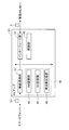
- FIG. 2 is a block diagram showing a configuration of the AV amplifier 13 in the living room 21, and shows only a part particularly related to the present invention.
- the AV amplifier 13 includes a signal processing unit 40, a wireless communication unit 41, an interface unit 47, and a control unit 48.
- the wireless communication unit 41 extracts music data D1 from data received from the smartphone 11 via wireless communication.
- a stereo L (left) channel acoustic signal and an R (right) channel acoustic signal include low-frequency dedicated (LFE (Low Frequency) Effect) channel acoustic signals.
- the added 2.1ch sound signal is included.
- the music data D1 does not include the low-frequency dedicated channel acoustic signal
- the low-frequency component generated based on the low-frequency component extracted from the L-channel acoustic signal and the R-channel acoustic signal is LFE. It may be an acoustic signal of a channel.
- the AV amplifier 13 of the present embodiment transfers an LFE channel acoustic signal (an example of additional information) in each of the 2ch acoustic signals.
- the signal processing unit 40 generates music data D2 and D3 by including the LFE channel acoustic signal in each of the L channel and R channel acoustic signals (hereinafter referred to as “signal generation processing”). There is).
- the music data D2 and D3 generated by the signal processing unit 40 are transmitted as a packet P from the interface unit 47 to the network 19.
- the signal processing unit 40 includes an AM (Amplitude Modulation) modulation unit 43, a Bit extension unit 44, and a frequency extension unit 45.
- the AM modulation unit 43 executes signal generation processing using an AM modulation method.
- the Bit extension unit 44 executes signal generation processing by the Bit extension method.
- the frequency extension unit 45 executes signal generation processing by a sampling frequency extension method.
- the AM modulation method, the Bit extension method, and the sampling frequency extension method may be collectively referred to as a “transfer method”.
- the transfer method is an example of a “signal generation processing method”.
- the control unit 48 is a device that performs overall control of the AV amplifier 13.
- the control unit 48 selects an execution subject of signal generation processing from the AM modulation unit 43, the bit expansion unit 44, and the frequency expansion unit 45.
- the control unit 48 selects one transfer method from the three types of transfer methods, that is, the AM modulation method, the bit extension method, and the sampling frequency extension method, and the signal is transmitted by the selected one transfer method. Run the generation process.
- the AM modulation unit 43, the Bit extension unit 44, and the frequency extension unit 45 can be realized by, for example, a sound processing DSP (Digital Signal Processor) executing a predetermined program. Further, the AM modulation unit 43, the Bit extension unit 44, and the frequency extension unit 45 may be realized by, for example, an analog circuit or may be realized by executing a program on the CPU.
- DSP Digital Signal Processor
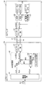
- FIG. 3 is a block diagram showing a connection relationship between the AV amplifier 13 in the living room 21 and the AV amplifier 14 in the study room 23, and only the part related to the AM modulation unit 43 is shown in the AV amplifier 13.
- the AM modulation unit 43 includes two adders 51 and 52, a modulation processing unit 55, and a carrier generation unit 56.
- the adder 51 corresponds to the L channel. That is, the L channel acoustic signal among the acoustic signals extracted from the music data D1 by the wireless communication unit 41 is input to the adder 51.
- the adder 52 corresponds to the R channel.
- the R channel acoustic signal among the acoustic signals extracted from the music data D1 by the wireless communication unit 41 is input to the adder 52.
- an acoustic signal of the LFE channel is input from the wireless communication unit 41 to the modulation processing unit 55.
- the acoustic signals of the L channel, the R channel, and the LFE channel are acoustic signals sampled at 48 kHz, for example.
- the modulation processing unit 55 downsamples the acoustic signal of the LFE channel.
- the carrier generation unit 56 outputs the carrier signal CS to the modulation processing unit 55.
- the modulation processing unit 55 performs AM modulation on the carrier signal CS input from the carrier generation unit 56 using the sample value of the down-sampled LFE channel acoustic signal, and a modulated signal (hereinafter referred to as “modulation signal MS”). Is output to the adders 51 and 52.
- the carrier generation unit 56 outputs a signal in a frequency band that is difficult to be heard by human ears as the carrier signal CS.
- a 2ch audio device for example, the TV 17
- multichannel (2.1ch) playback does not feel uncomfortable as 2ch music data even if the received music data D2 and D3 are played back as they are. Stereo sound can be reproduced with sound.
- an LFE channel acoustic signal sampled at a sampling frequency of 48 kHz is down-sampled by 1/8.
- the carrier signal CS a signal in a band that is difficult to be heard by the human ear is used as the carrier signal CS.
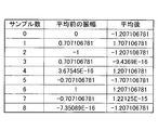
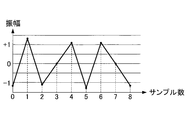
- FIG. 4A shows sample values of eight samples sampled from three periods of a 18 kHz sine wave having an amplitude of “1” (ie, eight samples included in one period of the carrier signal CS). Each value).
- FIG. 4B shows a waveform for one cycle of the carrier signal CS. In the following, the sample value may be referred to as a sample amplitude value.
- the carrier generation unit 56 outputs the carrier signal CS shown in FIG. 4B to the modulation processing unit 55.
- the modulation processing unit 55 performs AM modulation on the carrier signal CS input from the carrier generation unit 56 by using a sample value (volume level) obtained by down-sampling the acoustic signal of the LFE channel input from the wireless communication unit 41 by 1/8. Output to the adders 51 and 52. Since this signal is an acoustic signal of 18 kHz, even if it is reproduced as it is on the reproduction side, it becomes a sound that is extremely difficult to hear by human ears.
- the adder 51 adds the modulation signal MS output from the modulation processing unit 55 to the L channel acoustic signal sampled at 48 kHz, and interfaces as an L channel acoustic signal (music data D2).
- the adder 52 adds the modulation signal MS output from the modulation processing unit 55 to the R channel acoustic signal sampled at 48 kHz, and outputs the result to the interface unit 47 as an R channel acoustic signal (music data D3).
- the interface unit 47 packetizes the L-channel music data D2 input from the adder 51 and the R-channel music data D3 input from the adder 52, and packetizes the AV amplifier 14 via the network 19 as a packet P. Forward to.
- the interface unit 61 of the AV amplifier 14 receives the packet P from the interface unit 47 of the AV amplifier 13.
- the interface unit 61 extracts music data D2 corresponding to the L channel and music data D3 corresponding to the R channel from the received packet P.
- the interface unit 61 outputs the music data D2 corresponding to the L channel to a BEF (Band Elimination Filter) 63.
- the BEF 63 is a filter that allows passage of music data D2 corresponding to the L channel other than a signal in a predetermined frequency band.
- the BEF 63 outputs, to the speaker 39 corresponding to the L channel, an acoustic signal from which the 18 kHz AM modulation component unnecessary for the L channel is removed from the music data D2.
- the interface unit 61 outputs music data D3 corresponding to the R channel to the BEF 64.
- the BEF 64 is a filter that allows passage of music data D3 corresponding to the R channel other than signals in a predetermined frequency band.
- the BEF 64 outputs to the speaker 39 corresponding to the R channel an acoustic signal obtained by removing the 18 kHz AM modulation component unnecessary for the R channel from the music data D3.
- the interface unit 61 outputs the music data D2 corresponding to the L channel and the music data D3 corresponding to the R channel to the demodulation processing unit 67.
- the demodulation processing unit 67 downsamples the acoustic signals included in the input music data D2 and D3 by 1/8 and multiplies the 1/8 downsampled signal by a sine wave of 18 kHz.
- the demodulation processing unit 67 firstly down-samples the acoustic signals included in the music data D2 and D3 input to the demodulation processing unit 67 by 1/8, whereby a plurality of modulation signals MS have Take a sample value.
- the demodulation processing unit 67 extracts the amplitude value of the demodulation signal MD by multiplying the extracted modulation signal MS by a sine wave of 18 kHz.
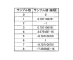
- FIG. 5 shows, as an example, assuming that the amplitude value of the modulation signal MS is “1.0”, 8 sample values (amplitude before multiplication) included in one period of the modulation signal MS, and 8 included in the modulation signal MS.
- 8 shows eight sample values (amplitude after multiplication) of the demodulated signal MD obtained by multiplying each sample value by a sine wave of 18 kHz.
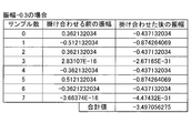
- FIG. 6 shows, as an example, the amplitude value of the modulation signal MS is set to “ ⁇ 0.3”, eight sample values (amplitude before multiplication) included in one period of the modulation signal MS, and the modulation signal MS.
- 8 shows eight sample values (amplitude after multiplication) of the demodulated signal MD obtained by multiplying eight sample values by a sine wave of 18 kHz. As shown in FIG.
- the total value “4” of the eight sample values included in one cycle of the demodulated signal MD is four times the amplitude value “1” of the modulation signal MS.
- the total value “ ⁇ 1.2” of the eight sample values included in one period of the demodulated signal MD is four times the amplitude value “ ⁇ 0.3” of the modulation signal MS. It has become. That is, the total value of the eight sample values included in one cycle of the demodulated signal MD is four times the amplitude value of the modulation signal MS. Therefore, the amplitude value of the modulation signal MS can be extracted by multiplying the total value of the eight sample values included in one period of the demodulation signal MD by 1/4.
- the demodulation processing unit 67 includes a plurality of demodulated signals MD so that the amplitude of the demodulated signal MD is 1 ⁇ 4 times the sum of the eight sample values of one period of the demodulated signal MD.
- the LFE channel acoustic signal is demodulated by correcting the sample value and up-sampling the demodulated signal MD after the correction by 8 times.
- 5 and 6 illustrate the case where the modulation signal MS and the carrier signal CS have the same waveform for convenience of explanation.
- the following two problems can be considered in the AM modulation system described above.
- a signal (modulated signal MS) obtained by AM-modulating the 18 kHz band signal originally included in the L-channel acoustic signal and the R-channel acoustic signal as a noise component. Therefore, it is necessary for the demodulation processing unit 67 to extract only the modulation signal MS so as not to be affected by the original L channel acoustic signal or the original R channel acoustic signal as much as possible.
- the adder 51 and the adder 52 superimpose the modulation signal MS on the L-channel acoustic signal and the R-channel acoustic signal.
- the demodulation processing unit 67 it is difficult for the demodulation processing unit 67 to detect the start position of the period of the modulation signal MS. That is, in the demodulation processing unit 67, the reference sample value (for example, the first sample value in the period of the modulation signal MS) among the plurality of sample values of the modulation signal MS and the 18 kHz sine wave reference Even if an attempt is made to multiply a plurality of sample values possessed by the modulation signal MS and a sine wave of 18 kHz after aligning the positions (for example, the position where the phase is “0”), it becomes a reference possessed by the modulation signal MS. It may be difficult to detect the sample value.
- the reference sample value for example, the first sample value in the period of the modulation signal MS
- the demodulation processing unit 67 there is a possibility that a plurality of sample values of the modulation signal MS and the 18 kHz sine wave may be multiplied without matching the reference, and the acoustic signal of the LFE channel cannot be accurately demodulated. There is a fear.
- the AM modulation unit 43 of the AV amplifier 13 that is the transfer source adds the modulation signal MS to the L-channel acoustic signal and the R-channel acoustic signal according to the following rules.
- a general music signal is likely to contain many in-phase components such as a vocal component as signal components of the L channel and the R channel.
- This in-phase component can be removed, for example, by subtracting the R channel acoustic signal from the L channel acoustic signal (Lch-Rch). Therefore, for example, the adder 51 adds the modulation signal MS to the L channel acoustic signal as an in-phase component.
- the adder 52 adds the modulation signal MS to the R channel acoustic signal as an antiphase component.
- the in-phase component included in the L-channel acoustic signal and the R-channel acoustic signal is “C” and the modulation signal MS component is “D”
- the demodulation processing unit 67 of the AV amplifier 14 that is the transfer destination subtracts the R channel acoustic signal from the L channel acoustic signal (Lch-Rch) as represented by the following equation (1).
- the demodulation processing unit 67 can remove the in-phase component C and extract only “D” that is the modulation signal MS.
- the signal “2D” extracted in the expression (1) has twice the amplitude as compared with the original signal “D”, the noise ratio (S / N ratio) is increased to suppress the influence of noise. Is done.
- a general music signal may contain many low-frequency components and human voice band components (for example, 1 kHz). This low-frequency component or the like has a small waveform fluctuation for each sample. Therefore, the demodulation processing unit 67 at the transfer destination, for example, in each of the transferred music data D2 and D3, the samples before and after among the plurality of samples included in the music data D2 and D3 are represented by the following formulas. The original L channel and R channel signal components are removed by weighting so as to cancel each other and calculating the moving average value.
- the demodulation processing unit 67 converts each sample value of the monaural signal D extracted by the equation (1) according to the weighting conversion equation.
- FIG. 7A shows a plurality of sample values (amplitude before averaging) included in the modulation signal MS shown in FIG. 5 and sample values (after averaging) obtained by performing a moving average operation on the plurality of sample values. Shows the relationship.
- FIG. 7B shows a waveform of a signal after the above-described moving average calculation is performed on the modulation signal MS (hereinafter, also referred to as “average signal MA”).
- the demodulation processing unit 67 generates the average signal MA by performing the above-described moving average calculation on a plurality of sample values included in the modulation signal MS.
- the demodulation processing unit 67 extracts the demodulated signal MD by multiplying the averaged signal MA by a sine wave of 18 kHz.
- FIG. 8 shows, as an example, an averaged signal obtained by performing a moving average operation on a plurality of sample values of the modulation signal MS when the amplitude value of the modulation signal MS is “1.0”.
- Eight sample values of the demodulated signal MD obtained by multiplying the eight sample values of MA (amplitude before multiplication) and the eight sample values of the post-average signal MA by an 18 kHz sine wave (Amplitude after multiplication).
- FIG. 9 shows, as an example, after averaging, obtained by performing a moving average operation on a plurality of sample values of the modulation signal MS when the amplitude value of the modulation signal MS is “ ⁇ 0.3”.
- Eight samples of the demodulated signal MD obtained by multiplying the eight sample values of the signal MA (amplitude before multiplication) and the eight sample values of the signal MA after averaging by a sine wave of 18 kHz. Value (amplitude after multiplication).
- the total value “11.56585425” of the eight sample values that are the sample values for one period included in the demodulated signal MD is approximately 11.1 of the amplitude value “1.0” of the modulation signal MS. 6 times.
- the total value “ ⁇ 3.497056275” of eight sample values that are the sample values for one period included in the demodulated signal MD is the amplitude value “ ⁇ 0.3” of the modulation signal MS. About 11.6 times.
- the demodulation processing unit 67 is configured so that the amplitude of the demodulated signal MD is “1 / 11.6585425” times the total value of the sample values for one period included in the demodulated signal MD.
- the LFE channel acoustic signal is demodulated by correcting a plurality of sample values of the demodulated signal MD and up-sampling the demodulated signal MD after the correction by 8 times.
- the demodulation processing unit 67 removes the components of the L channel and R channel acoustic signals from the music data D2 and D3, and the original signals (L channel acoustic signals and R channel acoustic signals) are obtained.
- the influence on the modulation signal MS as a noise component is reduced to solve the first problem.
- the demodulation processing unit 67 first determines a provisional start position that is a provisional sample start position from among a plurality of samples included in the averaged signal MA.
- the demodulation processing unit 67 sets the provisional start position as the first sample position, and the range from the first sample position to the eighth sample position (that is, a range corresponding to one cycle of the averaged signal MA), Set as provisional sample range.
- the demodulation processing unit 67 aligns the provisional start position and the reference position of the 18 kHz sine wave, and then adds the 18 kHz sine to each sample value of the eight samples of the averaged signal MA in the provisional sample range. By multiplying the waves, the sample values of each of the eight samples of the demodulated signal MD in the provisional sample range are calculated.
- the demodulation processing unit 67 sums the eight sample values of the demodulated signal MD in the provisional sample range.
- the demodulation processing unit 67 repeats the process for calculating the total value of the eight sample values of the demodulated signal MD in the provisional sample range described above, for example, eight times while changing the provisional start position one by one. Then, the demodulation processing unit 67 determines the provisional start position where the absolute value of the total value of the eight sample values of the demodulated signal MD in the provisional sample range is the largest as the sample start position (the sample position corresponding to the reference sample value). ).
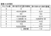
- FIG. 10 shows, for each of the cases where the provisional start position is changed from “0” to “6”, the eight sample values of the demodulated signal MD in the provisional sample range and the total value of the eight sample values.
- FIG. 10 as in FIG. 8, the case where the amplitude value of the modulation signal MS is “1.0” is assumed as an example. Further, in FIG. 10, it is assumed as an example that the sample position “0” is a reference position of an 18 kHz sine wave (for example, a start position of an 18 kHz sine wave waveform). As shown in FIG.
- the demodulated signal MD in the temporary sample range is the maximum value (11.6655854).
- the temporary sample range is “1 to 8” and the temporary start position “1” is different from “0” which is the reference position of the 18 kHz sine wave, the eight demodulated signals MD in the temporary sample range
- the absolute value of the total value of the sample values is a smaller value (8.2426406687) than the maximum value (11.65685425).
- the demodulation processing unit 67 sets the temporary start position where the absolute value of the total value of the eight sample values of the demodulated signal MD in the temporary sample range is the largest as the sample start position, thereby allowing the music data D2 and It is possible to appropriately set the position where the sine wave is multiplied to D3 or the signal D that has been made monaural.
- the absolute value of the total value of the eight sample values of the demodulated signal MD in the provisional sample range is the maximum value (11.65685425). It becomes.
- the LFE signal that is the object of AM modulation is a low-frequency component and the difference for each sample is small, the sign is set regardless of which sample position “0” or sample position “4” is set as the start position.
- the error as a signal after multiplying waves is small. For example, if the original signal before AM modulation is set to a positive value in advance, the maximum positive value can be detected as the start position.
- the transfer source modulation processing unit 55 performs “(sample value) * 0.5 + 0” for the carrier signal CS whose sample value is in the range of “ ⁇ 1.0 to +1.0”. .5 ", the entire waveform of the carrier signal CS is set to a positive value.
- a provisional start position where the maximum value of the total value of the eight sample values of the demodulation signal MD in the provisional sample range is positive is set as the sample start position, and each sample included in the demodulation signal MD is set.
- An LFE channel signal can be extracted by calculating “(sample value ⁇ 0.5) * 2.0” and inversely converting the value.
- the modulation processing unit 55 performs AM modulation on the carrier signal CS generated based on the 18 kHz sine wave is described, but the present invention is not limited thereto.
- the modulation processing unit 55 may AM modulate the LFE channel acoustic signal using the carrier signal CS in a frequency band higher than the audible band, and add the result to the L channel acoustic signal and the R channel acoustic signal.
- the carrier signal CS is AM-modulated by the LFE channel acoustic signal that is 1/8 down-sampled. can do.
- the music data D1 does not include a high frequency component such as 192 kHz, the signal included in the music data D1 does not affect the noise.
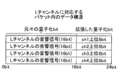
- the bit extension unit 44 mixes and transfers a plurality of channel signals using an empty area of the quantization bit of the acoustic signal.
- music content on a CD Compact Disc
- a value of “0” is set to the minimum 8 bits. Therefore, the bit extension unit 44 uses a minimum of 8 bits to extend each of the L-channel acoustic signal and the R-channel acoustic signal quantized with 16 bits to 24 bits.
- the sound signal of the channel is transferred. This minimum 8 bits is relatively small in volume (sound pressure level). Therefore, even if an audio signal of another channel is set and reproduced with 24 bits, it becomes a volume region that is hard to be heard by human ears, and it is possible to reproduce a sound with a little uncomfortable feeling at the transfer destination.
- FIG. 11 shows an example of the data structure of the packet P transferred on the network 19, and after the bit is expanded.
- the bit extension unit 44 uses 24 bits for each of the L channel acoustic signal and the R channel acoustic signal quantized with 16 bits among the acoustic signals extracted from the music data D1 by the wireless communication unit 41 (see FIG. 2). Perform extension processing so that it can be transferred.
- the bit extension unit 44 adds and transfers, for example, an acoustic signal of the LFE channel to a data area of at least 8 bits that increases by extending from 16 bits to 24 bits. Specifically, when the LFE channel acoustic signal is quantized with 16 bits, the Bit extension unit 44, as shown in FIG.
- the Bit extension unit 44 sets the lower 8 bits of the LFE channel acoustic signal in the extension region of the R channel acoustic signal and outputs the lower 8 bits to the interface unit 47 as music data D3.
- the interface unit 47 packetizes and transfers the music data D2 and D3 in the same packet P.
- the destination audio device performs processing according to the number of available channels.
- the bit values of the extended areas of the L-channel acoustic signal and the R-channel acoustic signal extracted from the packet P are cleared to zero and output to the speaker 35. That is, the audio device such as the TV 17 includes a “invalidation unit” that clears the bit value of the extension area of the acoustic signal to zero, and a “reproduction unit” that reproduces the invalidated signal.
- the TV 17 sets a dither signal (non-correlated noise) as the bit value of the extended area and outputs it to the speaker 35.
- the speaker 35 can reproduce the sound of the L channel and the R channel included in the music data D2 and D3. Moreover, even if the TV 17 is not compatible with the above-described invalidation processing of the extended area, the minimum 8-bit of 24 bits is a volume area that is hard to be heard by human ears as described above. However, it can be considered that the influence of noise is very small.
- the upper 8 bits and the lower 8 bits of the LFE channel acoustic signal are extracted from the packet P as a process of reproducing the acoustic signal of the LFE channel. Also, the AV amplifier 14 combines the upper 8 bits and the lower 8 bits of the extracted LFE channel acoustic signal, and generates an LFE channel acoustic signal that is a low-frequency acoustic signal quantized by 16 bits. The AV amplifier 14 outputs the generated LFE channel acoustic signal to the speaker 39.
- the audio equipment such as the AV amplifier 14 includes an “additional information acquisition unit” that extracts the upper 8 bits and the lower 8 bits of the acoustic signal of the LFE channel, and an “output unit” that outputs the extracted acoustic signal of the LFE channel. . Further, the AV amplifier 14 performs processing for reproducing the L-channel acoustic signal and the R-channel acoustic signal in the same manner as the TV 17, and extends each of the L-channel acoustic signal and the R-channel acoustic signal extracted from the packet P. Is cleared to zero and output to the speaker 39. In this Bit extension method, since the sound signals of a plurality of channels can be included in the same packet P, and the number of samples can be aligned and transferred in the same packet P, the sound output timing of each channel is aligned. It becomes easy.
- the Bit extension unit 44 can increase the above-described extension region (empty region) by increasing the sampling frequency, and mix other signals in the extension region, thereby simultaneously transferring more channels of acoustic signals and the like. It is possible. For example, a case will be described in which each of an L channel acoustic signal and an R channel acoustic signal sampled at 48 kHz is upsampled to 192 kHz.
- FIG. 12A shows a state in which the up-sampled L-channel acoustic signal is expanded from 16 bits to 24 bits, and the acoustic signals of other channels are set in the expanded region.
- FIG. 12B shows a state in which the up-sampled R channel acoustic signal is expanded from 16 bits to 24 bits, and the acoustic signals of other channels are set in the expanded region.
- the data amount of the signal up-sampled to 192 kHz is four times that of the original 48 kHz signal. For this reason, the data area of the expanded quantization bit is also quadrupled.
- the acoustic signal of the other channel can be arranged every four samples. .
- four types of signals of other channels quantized with 16 bits can be set in the extension region.
- the upper and lower 8 bits of the acoustic signal of the other channel are present in the extension region of the first (first sample) L channel and R channel from the top. Is set.
- the upper and lower 8 bits of the sound signals of ch2, ch3, and ch4 are set in the second (second sample) and subsequent extended areas. In this case, it is possible to transfer a total of 6 channels obtained by adding 4 channels in the extension area to the original L channel and R channel (2 channels).
- a process for aligning sampling frequencies is required as a transfer destination process.
- the transfer destination AV amplifier 14 up-samples the CH1-CH4 channel acoustic signal in the expansion region from 48 kHz to 192 kHz, or the L channel acoustic signal and the R channel acoustic signal each from 192 kHz to 48 kHz. Downsampling makes the sampling frequency uniform.
- FIGS. 13A and 13B show the data structure of the packet P when the L-channel acoustic signal and the R-channel acoustic signal are expanded to 32 bits.
- a 16-bit data area (16-bit to 32-bit) can be secured in each of the expansion areas of the L-channel acoustic signal and the R-channel acoustic signal.
- both the upper and lower (16 bits) of the sound signal of ch1 other than the L channel and the R channel are set in the extension region of the first L channel from the top. .
- both the upper and lower (16 bits) of the ch2 acoustic signal are set in the extension region of the first R channel from the top.
- the Bit expansion unit 44 can expand the number of bits and increase the number of channels that can be set in the expansion region.
- the frequency extension unit 45 increases the sampling frequency to secure an empty area between data, and mixes and transfers a plurality of channel signals using the reserved empty area. For example, when the sampling frequency of each of the L-channel acoustic signal and the R-channel acoustic signal is 48 kHz, the frequency extension unit 45 increases the sampling frequency to 96 kHz, which is doubled. In the case of normal upsampling, a sample value obtained by newly sampling the original signal is set for the increased sample.
- the frequency extension unit 45 of the present embodiment maintains the 48 kHz data without re-sampling, and sets data different from the original acoustic signal in the increased sample portion. As a result, it is possible to mix another channel signal or the like with the L channel acoustic signal and the R channel acoustic signal.
- FIG. 14 shows data of each sample in the acoustic signal of the L channel before raising the sampling frequency (48 kHz) and after raising the sampling frequency (96 kHz).
- the frequency extension unit 45 increases the sampling frequency from 48 kHz to 96 kHz, which is doubled, and ensures “empty samples 1 to 4” between samples.
- the frequency extension unit 45 inserts data of other channels (such as LFE channel) different from the L channel and R channel into the empty samples 1 to 4, thereby transferring twice the number of channels as signal data. Is possible.
- FIG. 14 shows only the L channel acoustic signal, but the same number of channels can be transferred to the R channel acoustic signal by executing the same processing.
- the frequency extension unit 45 can transfer data for a total of four channels including the L channel and the R channel (2ch) plus two additional channels.
- the transfer destination AV amplifier 14 can acquire each channel individually by extracting data of different channels from the packet P every other sample.
- the sampling frequency is increased only during transfer. Further, the AV amplifier 14 only needs to return the sampling frequency from 96 kHz to the original 48 kHz with respect to the acquired data, and no re-sampling process is required, and the original 2.1ch music data D1 can be reproduced. . Also, in the sampling frequency expansion method, unlike the normal upsampling process, the data of a plurality of channels are exchanged for each sample and transferred. Therefore, in the sampling frequency expansion method, since the sound signals of a plurality of channels are transferred separately for each sample, it is possible to ensure a higher transfer rate and sound quality than the above-described AM modulation method and Bit expansion method. It becomes.
- the LFE sound signal is mixed with the L channel sound signal and the R channel sound signal and transferred.
- the data to be mixed is not limited to an acoustic signal, and metadata (text data, control data, etc.) may be used.
- the AV amplifier 13 may transfer control data for changing the gain as the control data to be mixed.
- a process for securing a head margin is required as a pre-process for executing a digital domain process in a DSP or the like.
- a process for returning the head margin is required as a pre-process for reproduction in the analog area.
- the AV amplifier 13 performs preprocessing for securing a head margin of ⁇ 10 dB in order to prevent a clip from occurring in the digital domain for an acoustic signal of a 0 dB full-scale LFE channel.
- the AV amplifier 13 transmits the head margin amount ( ⁇ 10 dB) previously attenuated in the digital domain as control data to the transfer destination audio device (for example, a subwoofer that reproduces only the LFE channel).
- the transfer destination subwoofer Based on the control data, the transfer destination subwoofer amplifies the LFE channel acoustic signal by +10 dB in the processing of the analog domain, so that the signal level of the LFE channel acoustic signal becomes the L channel acoustic signal and the R channel acoustic signal. It is possible to reproduce the signal with the same signal level. As a result, it is possible to avoid the occurrence of a clip in the processing in the digital domain and transfer it with higher sound quality.
- metadata such as control data can be transmitted in addition to the acoustic signals of a plurality of channels or in place of the acoustic signals of the plurality of channels.
- the AV amplifier 13 may mix and transfer control data related to gain adjustment of a specific channel according to the request of the user U, and change the reproduction state of the transfer destination.
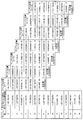
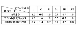
- FIG. 15 is an example of a table showing a relationship between a plurality of operation modes provided in the AV amplifier 13 and gain values of each of the multi-channel acoustic signals transferred by the AV amplifier 13.
- the AV amplifier 13 sets a gain value corresponding to each operation mode shown in FIG. 15 as control data, and transfers the mixed data in a 5.1ch multi-channel acoustic signal by each of the transfer methods described above.
- the transfer destination audio device for example, downmixes the received 5.1ch sound signal to 2ch and reproduces it.
- the transfer destination audio device realizes reproduction according to each operation mode by increasing / decreasing the signal level of each channel based on the gain value set in the control data.
- a gain value for each channel is set in the control data.
- the channel names L, C, R, SL, SR, and LFE in FIG. 15 indicate left (left), center, right (right), surround left, surround right, and low-frequency dedicated channels, respectively. Yes.
- the gain value “1.0 times (attenuation amount 0 dB)” is a signal level for reproducing normal music.
- the transfer destination audio device When the operation mode of the AV amplifier 13 is the karaoke mode, the transfer destination audio device performs mute “0 times (attenuation amount ⁇ dB)” and downmixes the center ch (Cch) containing a lot of vocal components. The voice of karaoke is reproduced by suppressing the voice of the vocal (see the bold part in FIG. 15).
- the surround channels SL and SR have a gain value of “0.7 times (attenuation amount ⁇ 3 dB)”. This is because the surround channels SL and SR need to be 0.7 times (attenuation amount ⁇ 3 dB) for level adjustment, for example, when 5.1ch is downmixed to 2ch.
- the transfer destination audio device downs the front side (Lch, Cch, and Rch) by “1.0 times (attenuation amount 0 dB)” as usual.
- the surround side (SLch and SRch) is reduced by “0.5 times (attenuation amount ⁇ 6 dB)” (refer to the bold portion in FIG. 15).
- the sound played from the destination audio device can be easily heard from the front side by suppressing the surround sound, which includes a lot of spectator voices, and emphasizing components such as vocal singing voices and player performance sounds. Sound.
- the transfer destination audio device When the operation mode of the AV amplifier 13 is the night trial listening mix mode, the transfer destination audio device lowers the Lch, Rch, and LFEch signal levels including a large volume signal and a lot of low-frequency components, The signal level of Cch containing a large amount of singing voice components is increased (see the bold portion in FIG. 15). For example, the transfer destination audio device multiplies the Lch and Rch signal levels by 0.7, multiplies the LFEch signal level by 0.3, and multiplies the Cch signal level by 1.4.
- the Cch signal level is increased to make it easier to hear the human voice and to suppress the low frequency component. It is possible to suppress vibrations and the like associated with music reproduction from causing inconveniences in the vicinity.
- the control unit 48 (see FIG. 2) of the AV amplifier 13 includes, for example, a data table in which gain values in the table shown in FIG. 15 are set in advance in a memory or the like, and performs each operation while referring to the data table.
- a signal level corresponding to the mode may be set as control data.
- the AV amplifier 13 may set a time stamp indicating the reproduction time of the music data D1 as metadata, and mix it with each of the L channel acoustic signal and the R channel acoustic signal. This makes it possible to align the sound output timings of the transfer source and the transfer destination.
- ⁇ Transfer of down-mixed sound signal> not only a normal 2ch sound signal but also a signal obtained by downmixing a conventionally used multi-channel to 2ch can be similarly transferred.
- the AV amplifier 13 can also mix and transfer the 5.1 channel signal to the L channel acoustic signal and the R channel acoustic signal downmixed to 2 channel by the above-described transfer methods.
- the destination audio device is a stereo speaker
- a downmixed 2ch sound signal can be reproduced.
- the transfer destination is a multi-channel speaker
- the down-mixed signal can be discarded and the multi-channel signal (5.1ch) included in the received signal can be separated and reproduced.
- the control unit 48 of the AV amplifier 13 (see FIG. 2), for example, “priority” when transferring the music data D1 to each audio device such as the AV amplifier 14 or the TV 17 and the transfer destination of the music data D1.
- An appropriate transfer method is selected based on the “processing performance” related to the music data D1 of the audio device. Note that the control unit 48 may select the transfer method based on either the priority or the processing performance.
- control unit 48 replaces one or both of the priority and the processing performance, or in addition to one or both of the priority and the processing performance, one of the number of channels of the music data D1 to be transferred and the content of the music data D1.
- the transfer method may be selected based on both.
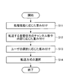
- the control unit 48 weights the transfer method according to the flowchart shown in FIG. 16 (see S11 to S13 in FIG. 16), and selects the transfer method based on the result. (Refer to S14 in FIG. 16).
- step S11 the control unit 48 weights the transfer method in accordance with the processing performance of the transfer destination audio device.
- step S11 the control unit 48 determines the processing performance of the transfer destination audio device. Regarding the determination of the processing performance, for example, the control unit 48 may determine based on the result of inquiring each audio device via the network 19 or may determine based on information input from the user U. Also good. Further, the control unit 48 may not directly inquire about the processing performance related to the music data D1.
- the control unit 48 may acquire only the performance information of the CPU of each audio device and estimate the processing performance related to the music data D1 based on the information.
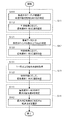
- FIG. 17 is a diagram showing an example of a detailed flowchart of FIG.
- the control unit 48 first acquires information (an example of “performance information”) related to the processing performance of the audio device to which the music data D1 is transferred in step S11. Then, based on the acquired information, it is determined whether or not the audio device has a predetermined processing performance (S111). Next, in step S11, the control unit 48 sets values for the priorities W1 to W3 according to the determination result in step S111 (S112).
- the priority W1 is an evaluation value indicating the degree of appropriateness of using the AM modulation method for transferring the music data D1.
- the priority W2 is an evaluation value indicating the appropriateness of using the Bit expansion method for transferring the music data D1.
- the priority W3 is an evaluation value indicating the degree of appropriateness of using the sampling frequency expansion method for transferring the music data D1.
- an audio device having a predetermined processing performance is expressed as “the audio device has a high processing performance”, and an audio device does not have the predetermined processing performance. It may be expressed as “the processing performance of the device is low”.
- the processing performance of the audio device to which the music data D1 is transferred is low (for example, when the audio device is a single speaker device), in the audio device, for example, in the demodulation processing unit 67 (see FIG. 3). It is assumed that an executable channel separation process cannot be executed. If the transfer destination audio device cannot perform the channel separation process, the music data D1 transfer method to the transfer destination audio device is a sound that does not cause a sense of incompatibility even if it is reproduced without performing the channel separation process.
- the reproducible AM modulation method and Bit expansion method are effective. Therefore, when the control unit 48 determines that the processing performance of the transfer destination audio device is low, the control unit 48 increases the priority of the AM modulation method and the Bit expansion method.
- the control unit 48 sets a value w ⁇ b> 11 to the priority W ⁇ b> 1 related to the AM modulation scheme, and relates to the Bit expansion scheme
- the value w21 is set to the priority W2, and “0” is set to the priority W3 related to the sampling frequency expansion method (the value w11 is a real number satisfying 0 ⁇ w11.
- the value w21 is a real number satisfying 0 ⁇ w21) ).
- step S11 when the processing performance of the audio device to which the music data D1 is transferred is high, a sampling frequency expansion method that can maintain high-quality sound quality with the least data loss in the signal generation processing is effective as the transfer method. Become. Therefore, when the control unit 48 determines in step S11 that the processing performance of the transfer destination audio device is high, the control unit 48 increases the priority of the sampling frequency expansion method. Specifically, as illustrated in FIG. 17, when the result of the determination in step S111 is affirmative, the control unit 48 sets “0” to the priority W1 related to the AM modulation scheme, and sets the Bit expansion scheme.
- the priority W2 is set to “0”, and the value w31 is set to the priority W3 related to the sampling frequency expansion method (value w31 is a real number satisfying 0 ⁇ w31). Even when the transfer destination audio device has high performance, transfer using the AM modulation method or Bit extension method can be executed. Therefore, when the determination result in step S111 is affirmative, the value w11 is set to the priority W1 related to the AM modulation scheme, the value w21 is set to the priority W2 related to the Bit expansion scheme, and the sampling frequency extension The value w31 may be set for the priority W3 related to the method.
- step S12 the control unit 48 weights the transfer method according to one or both of the number of channels of the music data D1 to be transferred and the content of the music data D1.
- the control unit 48 can directly detect the number of channels of the music data D1 to be transferred, for example, or can detect based on the input information of the user U or the like.
- step S12 for example, when the music data D1 is music content in which a band-limited LFE channel is added to the basic front side 2ch, such as 2.1ch, or the music data D1 is In the case of music content in which a signal that is relatively unquestionable such as an announcement signal (email arrival notification) is added to 2ch of the above, since the high sound quality (sampling frequency) is not required, the control unit 48 For example, the priority of the AM modulation scheme is increased. For example, as illustrated in FIG. 17, the control unit 48 first determines in step S12 whether, for example, the music data D1 has a channel number equal to or greater than a predetermined channel number (for example, 3ch) (S121).
- a predetermined channel number for example, 3ch
- values are set for the priorities W1 to W3 according to the determination result in step S121 (S122). More specifically, when the result of the determination in step S121 is negative, the control unit 48 adds the value w12 to the priority W1 related to the AM modulation scheme and “0” to the priority W2 related to the Bit expansion scheme. Also, “0” is added to the priority W3 related to the sampling frequency expansion method (value w12 is a real number satisfying 0 ⁇ w12).
- the control unit 48 increases the priority of the Bit expansion method, for example.
- the control unit 48 performs sampling capable of high-quality transfer. Increase the priority of the frequency extension method. Specifically, as illustrated in FIG. 17, when the determination result in step S121 is affirmative, the control unit 48 adds “0” to the priority W1 related to the AM modulation method, and sets the Bit extension method.
- the value w22 is added to the priority W2 and the value w32 is added to the priority W3 related to the sampling frequency extension method (the value w22 is a real number satisfying 0 ⁇ w22.
- the value w32 is a real number satisfying 0 ⁇ w32) ).
- the control unit 48 can select the transfer method according to the number of channels of the music data D1 and the content of the signal (such as sound quality). Note that the priority setting described above is an example, and for example, 2.1ch or a sampling frequency expansion method may be used.
- step S ⁇ b> 13 the control unit 48 weights the transfer method according to the operation content (priority) of the user U with respect to the remote control of the AV amplifier 13 or the operation button provided on the AV amplifier 13.
- the user U operates a remote controller or the like to operate three items (instructions) of “reduction of power consumption at a transfer destination”, “reduction of delay between a plurality of channels”, and “priority of high-resolution sound quality”.
- One item can be selected.
- the control unit 48 first acquires the operation content by the user U (S131), and then acquires the operation content of the user U acquired in step S131. Accordingly, values are set for the priorities W1 to W3 (S132).
- the AM modulation method and the Bit extension method can reproduce the L channel sound signal and the R channel sound signal as they are, if it is desired to reduce power consumption, the channel in the transfer destination audio device is used.
- the power consumption necessary for the separation process can be suppressed by stopping the separation process and regenerating the separation process. For this reason, when the user U selects “reduction of power consumption at the transfer destination”, an AM modulation method or a Bit expansion method that enables selection of the presence or absence of separation processing according to the power consumption becomes effective. Therefore, the control unit 48 increases the priority of the AM modulation method and the Bit expansion method when “reduction of power consumption at the transfer destination” is selected. Specifically, as illustrated in FIG.
- the control unit 48 sets a value for the priority W ⁇ b> 1 related to the AM modulation method.
- w13 is added, the value w23 is added to the priority W2 related to the Bit expansion method, and “0” is added to the priority W3 related to the sampling frequency expansion method (value w13 is a real number satisfying 0 ⁇ w13).
- the value w23 is a real number satisfying 0 ⁇ w23).
- the control unit 48 increases the priority of the Bit expansion method when “reduction of delay between a plurality of channels” is selected by the user U. Specifically, as illustrated in FIG. 17, when the operation content acquired in step S131 is “reduction in delay between a plurality of channels”, the control unit 48 sets the priority W1 related to the AM modulation scheme to “ "0" is added, the value w23 is added to the priority W2 related to the Bit extension method, and "0" is added to the priority W3 related to the sampling frequency extension method.
- the control unit 48 increases the priority of the sampling frequency expansion method. Specifically, as illustrated in FIG. 17, when the operation content acquired in step S131 is “high-res sound quality priority”, the control unit 48 sets “0” to the priority W1 related to the AM modulation method. Then, “0” is added to the priority W2 related to the Bit expansion method, and the value w33 is added to the priority W3 related to the sampling frequency expansion method (value w33 is a real number satisfying 0 ⁇ w33). In the present embodiment, it is assumed that the values w11 to w33 added to the priorities W1 to W3 in steps S11 to S13 are equal to each other, for example, “1”.
- step S14 the control unit 48 selects a transfer method based on the results of the weighting performed in steps S11 to S13. Specifically, as illustrated in FIG. 17, in step S14, the control unit 48 first specifies the maximum priority W among the priorities W1 to W3 (S141). Next, the control unit 48 selects a transfer method corresponding to the maximum priority W specified in step S141 (S142). More specifically, in step S142, when the maximum priority W specified in step S141 is the priority W1, the control unit 48 selects the AM modulation method and specifies the maximum priority specified in step S141. When the degree W is the priority W2, the Bit extension method is selected, and when the maximum priority W specified in step S141 is the priority W3, the sampling frequency extension method is selected.
- the control unit 48 selects one of the plurality of transfer methods corresponding to the plurality of priorities W. For example, the transfer method may be selected at random. As described above, the control unit 48 can transfer the music data D1 by an appropriate method by selecting the transfer method from the three transfer methods according to the priority and the processing performance.
- the AV amplifier 13 is an example of a “signal processing device”.
- the AV amplifier 14 and the TV 17 are examples of a “playback device”.
- the interface unit 47 is an example of a “transfer unit”.
- the control unit 48 functions as a “selection unit” by executing part or all of steps S11 to S14.
- the control unit 48 functions as an “acquisition unit” by executing step S111.
- the music data D1 is an example of an “acoustic signal”.
- the music data D2 and D3 are examples of “transfer signals”.
- the acoustic signal and metadata of the LFE channel are examples of “additional information”.
- the interface unit 61 is an example of a “reception unit”.
- the demodulation processing unit 67 is an example of an “additional information acquisition unit”.
- the L channel acoustic signal is an example of a “first signal”.
- the R channel acoustic signal is an example of a “second signal”.
- the transfer destination audio device (for example, the TV 17) is a device that does not support the transfer method, and the L channel sound signal and the R channel sound signal mixed with the LFE channel sound signal are used. Even if it is reproduced as it is, it is possible to reproduce it with a sound that does not feel strange.
- the network 19 to which the AV system 10 is applied there is an audio device equipped with an abundant DSP such as an AV amplifier 14, while the received music data is simply played back like a speaker device alone. There is also.
- the transfer method described above does not require high processing performance from the transfer destination audio device, and it is possible to reproduce the original 2ch music only with simple processing. Therefore, it is possible to appropriately transfer data in which a plurality of signals are mixed within a limited audio band between audio devices having different generations, performances, purposes, solutions, and the like.
- the above three transfer methods are relatively easy to process compared to the downmix encoding process performed in the conventional signal generation process. However, it is possible to cope with this by a simple firmware update or the like.
- the values w11 to w33 added to the priorities W1 to W3 in steps S11 to S13 are equal to each other.
- the present invention is not limited to such a mode.
- some or all of the values w11 to w33 added to the priorities W1 to W3 may be different from each other.
- the importance levels of steps S11 to S13 may be determined in advance based on the operation of the user U, and the values w11 to w33 may be determined according to the importance levels.
- values added to the priorities W1 to W3 in each step w11 to w33 may be defined as “value added in step S11”> “value added in step S12”> “value added in step S13”.
- the control unit 48 selects the transfer method of the music data D1 for each audio device to which the music data D1 is transferred, but the present invention is not limited to such a mode. Absent. For example, when there are a plurality of audio devices to which the music data D1 is transferred, the control unit 48 sets the transfer method of the music data D1 so that the same transfer method is applied to the plurality of audio devices. You may choose. In this case, for example, in step S111, the control unit 48 may determine whether or not all of the plurality of audio devices that are the transfer destinations of the music data D1 have predetermined processing performance.
- control unit 48 may select the transfer method of the music data D1 so that the same transfer method is applied to all the audio devices connected to the network 19. In this case, for example, in step S111, the control unit 48 may determine whether all the audio devices connected to the network 19 have a predetermined processing performance.
- control unit 48 selects the transfer method of the music data D1 according to the processing performance of the audio device, but the present invention is not limited to such an aspect.
- control unit 48 selects the transfer method of the music data D1 in accordance with the processing performance of the network 19 such as the transfer rate of the network 19 instead of the processing performance of the audio device or in addition to the processing performance of the audio device. May be.
- control unit 48 executes steps S11 to S14 when selecting the transfer method of the music data D1, but the present invention is not limited to such a mode.
- control unit 48 may execute at least one of steps S11 to S13 and step S14.
- the AV amplifier and the TV are exemplified as the audio device, but the present invention is not limited to such an aspect.
- an audio device in addition to an AV amplifier and a TV, devices such as an AV receiver, a PC (personal computer), a smartphone, and an audio playback device can be employed.
- the low-frequency LFE channel acoustic signal is added as additional information to each of the L-channel acoustic signal and the R-channel acoustic signal.
- the additional information may be a signal other than the acoustic signal of the LFE channel, for example, a signal such as a warning sound.
- the additional information is added to each of the L-channel acoustic signal and the R-channel acoustic signal, but the present invention is not limited to such an aspect.
- the additional information may be added to an acoustic signal such as a surround left (SL) channel and a center (C) channel.
- the AV amplifier 13 may change the transfer method for each transfer destination audio device. For example, the AV amplifier 13 may perform transfer with the AV amplifier 14 and the Bit expansion method while transferring with the TV 17 by the AM modulation method.
- the signal processing device includes a transfer unit that transfers a transfer signal in which additional information is added to the acoustic signal toward the playback device, and generates the transfer signal by adding the additional information to the acoustic signal.
- a signal processing unit capable of executing the signal generation processing by a plurality of methods, and a selection unit that selects a signal generation processing method executed by the signal processing unit.
- an appropriate transfer method can be selected from a plurality of signal generation processing methods (transfer methods). For this reason, in a reproducing
- the signal processing device further includes an acquisition unit that acquires performance information that is information related to processing performance of the playback device in the signal processing device according to the first aspect, and the selection unit includes: A signal generation processing method executed by the signal processing unit is selected based on the performance information acquired by the acquisition unit. According to this aspect, it is possible to select a transfer method according to the processing performance of the playback device.
- the signal processing device is the signal processing device according to the first or second aspect, in which the selection unit performs signal generation processing executed by the signal processing unit based on the number of channels of the acoustic signal. The method is selected. According to this aspect, it is possible to select a transfer method according to the number of channels of the acoustic signal.
- a signal processing device is the signal processing device according to any one of the first to third aspects, characterized in that the additional information is a low-frequency channel signal.
- the signal of the low-frequency channel is composed of only the low-frequency component, even when the additional information is reproduced as it is, it can be reproduced with a sound without a sense of incongruity.
- the additional information is a signal of a channel different from the channel of the acoustic signal.
- signals of a plurality of channels can be transferred as transfer signals.
- a signal processing device is the signal processing device according to any one of the first to fifth aspects, wherein the signal processing unit is within a band that is difficult to be heard by a human ear within an audible band, or It is characterized by having an AM modulation unit for AM-modulating a carrier signal having a frequency in a non-audible band using additional information and adding the AM-modulated signal to an acoustic signal.
- the signal processing unit AM-modulates the additional information, adds it to the acoustic signal, and transfers it.
- the AM modulation unit is a carrier signal having a frequency that is difficult to be heard by the human ear (a carrier signal having a frequency in a band that is difficult to hear by the human ear) or a carrier signal having a frequency that cannot be heard by the human ear (in a non-audible band).
- the carrier signal of the frequency of the signal) is modulated using the additional information.
- the AM modulation method has a lighter processing load than the encoding process related to downmixing that has been performed in the conventional transfer process, and the time and amount of accumulation of the signal before the process in the reproduction apparatus at the transfer destination are conventionally reduced. Compared to the encoding process, the processing load can be reduced in terms of memory usage.
- a signal processing device is the signal processing device according to the sixth aspect, wherein the additional information is a low-frequency channel signal, and the AM modulation unit down-samples the low-frequency channel signal. And AM modulation.
- the AM modulation unit mixes and transfers the low-frequency channel signal to the acoustic signal. Since the low-frequency channel signal is composed of only the low-frequency component, it can be reproduced with a sound that does not feel strange even if the sampling frequency is lowered. Therefore, the AM modulation unit performs AM modulation using a sample value obtained by down-sampling the low-frequency signal, so that a plurality of acoustic signals can be combined and transferred to a limited acoustic channel band signal.
- the AM modulation unit A transfer signal is generated.
- the AM modulation method is selected as the transfer method even when the playback device does not have the predetermined processing performance and, for example, the demodulation process for separating the acoustic signal and the low frequency signal cannot be performed. Therefore, even if a signal obtained by mixing an acoustic signal and a low-frequency signal is reproduced as it is, it can be reproduced with a sound that does not feel strange.
- a signal processing device is the signal processing device according to any one of the first to eighth aspects, wherein the signal processing unit expands and expands the quantization bit of the acoustic signal. It is characterized by comprising a Bit extension unit for setting additional information in the reserved data extension area. According to this aspect, it is possible to transfer a combination of a plurality of pieces of information in a limited acoustic channel band signal.
- the bit expansion method for example, since a single packet transferred on the network can include acoustic signals of a plurality of channels and can be transferred by including the same number of samples in the same packet, It is easy to align the sound output timing.
- the bit extension unit upsamples the acoustic signal to increase the extension region. It is characterized by. According to this aspect, by increasing the sampling frequency and increasing the amount of data that can be secured as an extension area, it becomes possible to transfer more additional information at once.
- a signal processing device is the signal processing device according to any one of the first to tenth aspects, wherein the additional information is control data for adjusting a gain of the acoustic signal.
- the additional information is control data for adjusting a gain of the acoustic signal.
- a signal processing device is the signal processing device according to any one of the first to eleventh aspects, wherein the selection unit is operated by the user of the signal processing device and the processing of the playback device. Based on at least one of the performances, a signal generation processing method to be executed by the signal processing unit is selected. According to this aspect, a transfer method suitable for the user's operation content or the processing performance of the playback device can be selected from a plurality of transfer methods.
- the signal processing device is the signal processing device according to the twelfth aspect, wherein the operation content is an instruction to reduce power consumption related to processing of the transfer signal in the reproduction device, It is an instruction for reducing a delay in sound output based on the acoustic signal in the reproduction apparatus, or an instruction for improving sound quality when the acoustic signal is reproduced in the reproduction apparatus.
- a transfer method that can reduce power consumption in the playback device, reduce output delay in the playback device, or improve sound quality in the playback device is selected from a plurality of transfer methods. be able to.
- the acoustic signal transfer method includes a step of selecting a signal generation processing method for generating a transfer signal by adding additional information to an acoustic signal from a plurality of methods; And a step of generating a transfer signal and a step of transferring the generated transfer signal to a reproducing apparatus by the signal generation processing of the above-described method.
- an appropriate transfer method can be selected from a plurality of signal generation processing methods (transfer methods).
- a signal processing system is a signal processing system including a signal processing device and a reproduction device, and the signal processing device uses a transfer signal in which additional information is added to an acoustic signal as a reproduction device.
- a signal processing unit capable of executing a signal generation process for generating a transfer signal by adding additional information to an acoustic signal, and a signal generation process performed by the signal processing unit.
- a selection unit that selects a method. According to this aspect, when additional information is added to an acoustic signal for transfer, an appropriate transfer method can be selected from a plurality of signal generation processing methods (transfer methods).
- a transfer method includes an extension step of extending a quantization bit of an acoustic signal, a setting step of setting additional information in an extension area of data secured by the extension, and an acoustic signal And a transfer step of transferring a transfer signal with additional information added thereto.
- the additional information is transferred in the area where the quantization bit is expanded. This makes it possible to transfer a combination of a plurality of pieces of information in a limited acoustic channel band signal.
- an acoustic signal of a plurality of channels can be included in one packet transferred on the network, and the same number of samples can be included and transferred in the same packet. It is easy to align the sound output timing of each channel.
- the transfer method according to a seventeenth aspect of the present invention is the transfer method according to the sixteenth aspect, wherein the expansion step further includes an increase step of upsampling the acoustic signal to increase the expansion region.
- the expansion step further includes an increase step of upsampling the acoustic signal to increase the expansion region.
- a transfer method is the transfer method according to the sixteenth or seventeenth aspect, wherein the acoustic signal has a plurality of channels of the acoustic signal, and the setting step includes the additional information of the plurality of channels. It is characterized by being divided and set in an extended region corresponding to each acoustic signal. According to this aspect, for example, additional information (acoustic signal) for one channel can be divided and transferred to an extension area of a plurality of channels. As a result, even additional information that cannot be transferred in one extension area can be efficiently transferred by being divided into extension areas for each channel.
- a playback device is a playback device that plays back an acoustic signal transferred by the transfer method according to any of the sixteenth to eighteenth aspects, and adds additional information to the acoustic signal.
- An additional information acquisition unit that acquires additional information from a transfer signal and an output unit that outputs additional information acquired by the additional information acquisition unit. According to this aspect, it is possible to reproduce the acoustic signal while outputting the additional information included in the extended region obtained by extending the quantization bit.
- the additional information is another acoustic signal, it is possible to reproduce the acoustic signal transferred together and the additional information (other acoustic signal) together.
- a playback device is a playback device that plays back an acoustic signal transferred by the transfer method according to any of the sixteenth to eighteenth aspects, and adds additional information to the acoustic signal.
- an invalidation unit that invalidates the additional information
- a reproduction unit that reproduces the invalidated acoustic signal are provided.
- this aspect by invalidating the additional information in the extension area (zero clear, etc.), it is possible to reproduce only the acoustic signal even if the additional information in the extension area is not output (reproduction processing, etc.). It becomes.
- the transfer method includes an AM modulation step of AM-modulating a carrier signal having a frequency within a audible band that is difficult to be heard by a human ear or within a non-audible band using additional information; And adding an AM-modulated signal to the acoustic signal to generate a transfer signal, and a transfer step of transferring the transfer signal.
- the carrier signal is AM-modulated using the additional information, added to the acoustic signal, and transferred.
- a carrier signal having a frequency that is difficult or inaudible to human ears is modulated using the additional information.
- the AM modulation method has a lighter processing load than the encoding process related to downmixing performed in the conventional transfer process, and the time and amount of accumulation of the signal before the process in the transfer destination audio device can be reduced. Compared to the encoding process, the processing load can be reduced in terms of memory usage.
- the transfer method according to a twenty-second aspect of the present invention is the transfer method according to the twenty-first aspect, wherein the additional information is a low-frequency channel signal, and further includes a down-sampling step of down-sampling the low-frequency channel signal. It is characterized by having. Since the low-frequency channel signal is composed of only the low-frequency component, it can be reproduced with a sound that does not feel strange even if the sampling frequency is lowered. According to this aspect, by performing AM modulation using a sample value obtained by down-sampling a low-frequency channel signal, it is possible to transfer a plurality of acoustic signals in combination with a limited acoustic channel band signal. .
- a transfer method is the transfer method according to the twenty-first or twenty-second aspect, in which the acoustic signal includes a first signal and a second signal, and in the adding step, AM is added to the first signal. It has a difference calculation step of adding the modulated signal, adding the opposite phase component of the AM modulated signal to the second signal, and calculating the difference between the first signal and the second signal at the transfer destination. According to this aspect, the in-phase component of the first and second signals can be removed by calculating the difference between the first signal and the second signal at the transfer destination.
- an AM-modulated signal added in phase with the first signal and added in reverse phase with the second signal can be extracted as a signal having an amplitude twice that of the original signal by calculating the difference. It becomes possible to suppress the influence of noise by increasing the noise ratio (S / N ratio).
- the transfer method according to the twenty-fourth aspect of the present invention is the transfer method according to the twenty-third aspect, further comprising a moving average value calculating step for calculating a moving average value for the additional information extracted in the difference calculation step. It is characterized by. According to this aspect, by calculating the moving average value with respect to the additional information extracted by the difference calculation, it is possible to cancel out the component with little change for each sample from the acoustic signal included in the additional information. Become.
Abstract
L'invention concerne un dispositif de traitement de signal comprenant: une unité de transfert qui transfère un signal de transfert comprenant un signal acoustique avec des informations jointes vers un dispositif de reproduction; une unité de traitement de signal qui peut mettre en œuvre, en fonction de plusieurs schémas, un processus de génération de signal pour générer le signal de transfert en joignant des informations jointes à un signal acoustique; et une unité de sélection qui choisit un schéma de processus de génération de signal devant être mis en œuvre par l'unité de traitement de signal.
Priority Applications (1)
| Application Number | Priority Date | Filing Date | Title |
|---|---|---|---|
| US15/935,693 US10165382B2 (en) | 2016-03-22 | 2018-03-26 | Signal processing device, audio signal transfer method, and signal processing system |
Applications Claiming Priority (6)
| Application Number | Priority Date | Filing Date | Title |
|---|---|---|---|
| JP2016-056751 | 2016-03-22 | ||
| JP2016056751A JP6519507B2 (ja) | 2016-03-22 | 2016-03-22 | 音響信号の転送方法及び再生装置 |
| JP2016-056752 | 2016-03-22 | ||
| JP2016056750A JP6575407B2 (ja) | 2016-03-22 | 2016-03-22 | オーディオ機器及び音響信号の転送方法 |
| JP2016-056750 | 2016-03-22 | ||
| JP2016056752A JP6544276B2 (ja) | 2016-03-22 | 2016-03-22 | 音響信号の転送方法 |
Related Child Applications (1)
| Application Number | Title | Priority Date | Filing Date |
|---|---|---|---|
| US15/935,693 Continuation US10165382B2 (en) | 2016-03-22 | 2018-03-26 | Signal processing device, audio signal transfer method, and signal processing system |
Publications (1)
| Publication Number | Publication Date |
|---|---|
| WO2017164156A1 true WO2017164156A1 (fr) | 2017-09-28 |
Family
ID=59899440
Family Applications (1)
| Application Number | Title | Priority Date | Filing Date |
|---|---|---|---|
| PCT/JP2017/011155 WO2017164156A1 (fr) | 2016-03-22 | 2017-03-21 | Dispositif de traitement de signal, procédé de traitement de signal acoustique, et système de traitement de signal |
Country Status (2)
| Country | Link |
|---|---|
| US (1) | US10165382B2 (fr) |
| WO (1) | WO2017164156A1 (fr) |
Cited By (2)
| Publication number | Priority date | Publication date | Assignee | Title |
|---|---|---|---|---|
| CN109901447A (zh) * | 2017-12-08 | 2019-06-18 | 郑州宇通客车股份有限公司 | 一种can总线扩展装置 |
| US11308968B2 (en) | 2019-12-06 | 2022-04-19 | Yamaha Corporation | Audio signal output device, audio system, and audio signal output method |
Families Citing this family (4)
| Publication number | Priority date | Publication date | Assignee | Title |
|---|---|---|---|---|
| US9986356B2 (en) * | 2012-02-15 | 2018-05-29 | Harman International Industries, Incorporated | Audio surround processing system |
| US10779105B1 (en) * | 2019-05-31 | 2020-09-15 | Apple Inc. | Sending notification and multi-channel audio over channel limited link for independent gain control |
| WO2022215025A1 (fr) * | 2021-04-07 | 2022-10-13 | Steelseries Aps | Appareil pour fournir des données audio à de multiples dispositifs logiques audio |
| CN113541867A (zh) * | 2021-06-30 | 2021-10-22 | 南京奥通智能科技有限公司 | 一种用于融合终端的远程通信模块 |
Citations (5)
| Publication number | Priority date | Publication date | Assignee | Title |
|---|---|---|---|---|
| JP2003502704A (ja) * | 1999-06-21 | 2003-01-21 | デジタル・シアター・システムズ・インコーポレーテッド | デコーダの互換性を失わない確立済み低ビット・レートのオーディオ・コード化システムの音質の改善 |
| JP2008028496A (ja) * | 2006-07-19 | 2008-02-07 | Sony Corp | デジタルデータ伝送方法およびデジタルデータ伝送装置 |
| JP2010119076A (ja) * | 2008-10-16 | 2010-05-27 | Sony Corp | 情報処理システム、表示装置、出力装置、情報処理装置、識別情報取得方法および識別情報供給方法 |
| JP2010171768A (ja) * | 2009-01-23 | 2010-08-05 | Sony Corp | 音声データ送信装置、音声データ送信方法、音声データ受信装置および音声データ受信方法 |
| JP2013174882A (ja) * | 2010-12-03 | 2013-09-05 | Yamaha Corp | コンテンツ再生装置およびコンテンツ処理方法 |
Family Cites Families (4)
| Publication number | Priority date | Publication date | Assignee | Title |
|---|---|---|---|---|
| EP1520362A1 (fr) * | 2002-06-28 | 2005-04-06 | Micronas GmbH | Procede de transmission de signaux audio sans fil pour un systeme audio spatial |
| JP4221446B2 (ja) * | 2006-12-14 | 2009-02-12 | パナソニック株式会社 | 映像音声出力機器、音声出力機器、映像音声再生機器、映像音声データ再生システム及び映像音声データ再生方法 |
| JP5531486B2 (ja) | 2009-07-29 | 2014-06-25 | ヤマハ株式会社 | オーディオ機器 |
| JP5304860B2 (ja) | 2010-12-03 | 2013-10-02 | ヤマハ株式会社 | コンテンツ再生装置およびコンテンツ処理方法 |
-
2017
- 2017-03-21 WO PCT/JP2017/011155 patent/WO2017164156A1/fr active Application Filing
-
2018
- 2018-03-26 US US15/935,693 patent/US10165382B2/en active Active
Patent Citations (5)
| Publication number | Priority date | Publication date | Assignee | Title |
|---|---|---|---|---|
| JP2003502704A (ja) * | 1999-06-21 | 2003-01-21 | デジタル・シアター・システムズ・インコーポレーテッド | デコーダの互換性を失わない確立済み低ビット・レートのオーディオ・コード化システムの音質の改善 |
| JP2008028496A (ja) * | 2006-07-19 | 2008-02-07 | Sony Corp | デジタルデータ伝送方法およびデジタルデータ伝送装置 |
| JP2010119076A (ja) * | 2008-10-16 | 2010-05-27 | Sony Corp | 情報処理システム、表示装置、出力装置、情報処理装置、識別情報取得方法および識別情報供給方法 |
| JP2010171768A (ja) * | 2009-01-23 | 2010-08-05 | Sony Corp | 音声データ送信装置、音声データ送信方法、音声データ受信装置および音声データ受信方法 |
| JP2013174882A (ja) * | 2010-12-03 | 2013-09-05 | Yamaha Corp | コンテンツ再生装置およびコンテンツ処理方法 |
Cited By (4)
| Publication number | Priority date | Publication date | Assignee | Title |
|---|---|---|---|---|
| CN109901447A (zh) * | 2017-12-08 | 2019-06-18 | 郑州宇通客车股份有限公司 | 一种can总线扩展装置 |
| CN109901447B (zh) * | 2017-12-08 | 2020-12-08 | 郑州宇通客车股份有限公司 | 一种can总线扩展装置 |
| US11308968B2 (en) | 2019-12-06 | 2022-04-19 | Yamaha Corporation | Audio signal output device, audio system, and audio signal output method |
| JP7419778B2 (ja) | 2019-12-06 | 2024-01-23 | ヤマハ株式会社 | オーディオ信号出力装置、オーディオシステム及びオーディオ信号出力方法 |
Also Published As
| Publication number | Publication date |
|---|---|
| US10165382B2 (en) | 2018-12-25 |
| US20180220249A1 (en) | 2018-08-02 |
Similar Documents
| Publication | Publication Date | Title |
|---|---|---|
| WO2017164156A1 (fr) | Dispositif de traitement de signal, procédé de traitement de signal acoustique, et système de traitement de signal | |
| JP4580210B2 (ja) | 音声信号処理装置および音声信号処理方法 | |
| TWI489887B (zh) | 用於喇叭或耳機播放之虛擬音訊處理技術 | |
| JP4732807B2 (ja) | オーディオ信号処理 | |
| RU2666316C2 (ru) | Аппарат и способ улучшения аудиосигнала, система улучшения звука | |
| CA2835463C (fr) | Appareil et procede de generation d'un signal de sortie au moyen d'un decomposeur | |
| US20150208168A1 (en) | Controllable Playback System Offering Hierarchical Playback Options | |
| TW200837718A (en) | Apparatus and method for generating an ambient signal from an audio signal, apparatus and method for deriving a multi-channel audio signal from an audio signal and computer program | |
| KR20160015317A (ko) | 오디오 장면 장치 | |
| JP2002078100A (ja) | ステレオ音響信号処理方法及び装置並びにステレオ音響信号処理プログラムを記録した記録媒体 | |
| JP2007101871A (ja) | 補間装置、オーディオ再生装置、補間方法および補間プログラム | |
| JP2005507584A (ja) | サウンドアルゴリズムの選定方法とその装置 | |
| JP5058844B2 (ja) | 音声信号変換装置、音声信号変換方法、制御プログラム、および、コンピュータ読み取り可能な記録媒体 | |
| JP6575407B2 (ja) | オーディオ機器及び音響信号の転送方法 | |
| JP5202021B2 (ja) | 音声信号変換装置、音声信号変換方法、制御プログラム、および、コンピュータ読み取り可能な記録媒体 | |
| JP6544276B2 (ja) | 音響信号の転送方法 | |
| JP6519507B2 (ja) | 音響信号の転送方法及び再生装置 | |
| JP4462350B2 (ja) | 音声信号処理装置および音声信号処理方法 | |
| JP5224586B2 (ja) | オーディオ信号補間装置 | |
| JP2015065551A (ja) | 音声再生システム | |
| US10917108B2 (en) | Signal processing apparatus and signal processing method | |
| JPWO2013094135A1 (ja) | 音分離装置、および音分離方法 | |
| AU2020262159B2 (en) | Apparatus, method or computer program for generating an output downmix representation | |
| JP4815986B2 (ja) | 補間装置、オーディオ再生装置、補間方法および補間プログラム | |
| JP4715385B2 (ja) | 補間装置、オーディオ再生装置、補間方法および補間プログラム |
Legal Events
| Date | Code | Title | Description |
|---|---|---|---|
| NENP | Non-entry into the national phase |
Ref country code: DE |
|
| 121 | Ep: the epo has been informed by wipo that ep was designated in this application |
Ref document number: 17770198 Country of ref document: EP Kind code of ref document: A1 |
|
| 122 | Ep: pct application non-entry in european phase |
Ref document number: 17770198 Country of ref document: EP Kind code of ref document: A1 |