WO2017164047A1 - Dispositif d'écran - Google Patents
Dispositif d'écran Download PDFInfo
- Publication number
- WO2017164047A1 WO2017164047A1 PCT/JP2017/010558 JP2017010558W WO2017164047A1 WO 2017164047 A1 WO2017164047 A1 WO 2017164047A1 JP 2017010558 W JP2017010558 W JP 2017010558W WO 2017164047 A1 WO2017164047 A1 WO 2017164047A1
- Authority
- WO
- WIPO (PCT)
- Prior art keywords
- locking
- screen
- guide
- support rail
- edge
- Prior art date
Links
Images


Classifications
-
- E—FIXED CONSTRUCTIONS
- E06—DOORS, WINDOWS, SHUTTERS, OR ROLLER BLINDS IN GENERAL; LADDERS
- E06B—FIXED OR MOVABLE CLOSURES FOR OPENINGS IN BUILDINGS, VEHICLES, FENCES OR LIKE ENCLOSURES IN GENERAL, e.g. DOORS, WINDOWS, BLINDS, GATES
- E06B9/00—Screening or protective devices for wall or similar openings, with or without operating or securing mechanisms; Closures of similar construction
- E06B9/52—Devices affording protection against insects, e.g. fly screens; Mesh windows for other purposes
- E06B9/54—Roller fly screens
-
- E—FIXED CONSTRUCTIONS
- E06—DOORS, WINDOWS, SHUTTERS, OR ROLLER BLINDS IN GENERAL; LADDERS
- E06B—FIXED OR MOVABLE CLOSURES FOR OPENINGS IN BUILDINGS, VEHICLES, FENCES OR LIKE ENCLOSURES IN GENERAL, e.g. DOORS, WINDOWS, BLINDS, GATES
- E06B9/00—Screening or protective devices for wall or similar openings, with or without operating or securing mechanisms; Closures of similar construction
- E06B9/02—Shutters, movable grilles, or other safety closing devices, e.g. against burglary
-
- E—FIXED CONSTRUCTIONS
- E06—DOORS, WINDOWS, SHUTTERS, OR ROLLER BLINDS IN GENERAL; LADDERS
- E06B—FIXED OR MOVABLE CLOSURES FOR OPENINGS IN BUILDINGS, VEHICLES, FENCES OR LIKE ENCLOSURES IN GENERAL, e.g. DOORS, WINDOWS, BLINDS, GATES
- E06B9/00—Screening or protective devices for wall or similar openings, with or without operating or securing mechanisms; Closures of similar construction
- E06B9/56—Operating, guiding or securing devices or arrangements for roll-type closures; Spring drums; Tape drums; Counterweighting arrangements therefor
- E06B9/58—Guiding devices
-
- E—FIXED CONSTRUCTIONS
- E06—DOORS, WINDOWS, SHUTTERS, OR ROLLER BLINDS IN GENERAL; LADDERS
- E06B—FIXED OR MOVABLE CLOSURES FOR OPENINGS IN BUILDINGS, VEHICLES, FENCES OR LIKE ENCLOSURES IN GENERAL, e.g. DOORS, WINDOWS, BLINDS, GATES
- E06B9/00—Screening or protective devices for wall or similar openings, with or without operating or securing mechanisms; Closures of similar construction
- E06B9/52—Devices affording protection against insects, e.g. fly screens; Mesh windows for other purposes
- E06B9/54—Roller fly screens
- E06B2009/543—Horizontally moving screens
Definitions
- the present invention relates to a screen device attached to a building opening for light shielding, heat insulation, blindfolding, insect repellent, pollen invasion prevention and the like.
- a screen for shading, heat insulation, blindfolding, insect repellent, prevention of pollen entry, etc. is stretched in the screen frame to be installed in the opening of the building, and this screen can be moved laterally within the screen frame.
- Screen devices that open and close are known as disclosed in Patent Document 1, Patent Document 2, and the like.
- the screen device has screen guides that support upper and lower ends of the screen stretched on the screen frame.
- This screen guide is for preventing the screen from being greatly bent by the action force of wind or the like, and is formed by connecting a plurality of guide pieces in series and in a freely bendable manner at the end of the screen.
- the end of the screen is supported in a straight line by being arranged along the straight line.
- the screen guide 60 is installed horizontally on the lower side of the screen frame so that the screen 61 will not be displaced with the screen 61 when the screen 61 receives a lateral force.
- the rail 62 is supported by the rail 62 by fitting it into a concave groove 64 formed on the bottom surface of the guide piece 63.
- a pair of locking edges 62a and 62a projecting in the width direction are formed on the rail 62, and a pair of engagement edges are formed on the groove wall of the concave groove of the guide piece 63. It is desirable to form the pawls 64a and 64a and to lock the pawls 64a and 64a to the latching edges 62a and 62a.
- the screen guide as disclosed in FIG. 1 of Patent Document 1, is led into and out of the operation rod in accordance with the opening / closing operation of the screen (first type), and Patent Document As shown in FIG. 5 of FIG. 1, there is one (second type) that is led out into the left or right vertical frame ridge (fixed frame) of the screen frame.
- the configuration of the rail 62 and the guide piece 63 shown in FIG. 23 can be applied only to the second type screen guide among the two types of screen guides (see paragraph [0052] and FIG. 11c). This is because the distance between the pair of locking claws 64a, 64a of the guide piece 63 is smaller than the distance between the tip ends of the pair of locking edges 62a, 62a of the rail. 64a must be locked to the locking edges 62a and 62a from the end in the length direction of the rail 62, and cannot be locked to the locking edge at an intermediate position of the rail. It is.
- the rail 62 and the guide piece shown in FIG. 23 are also used in the first type of screen guide, that is, the type of screen guide that is pulled into or pulled out of the operating rod that moves along the rail. It is desired that 63 configurations can be applied.
- the technical problem of the present invention is to lock a screen guide that is pulled into or pulled out of the operating rod in accordance with the opening / closing operation of the screen by the operating rod at an intermediate position of the supporting rail. Or to be separated from the support rail.
- a screen device of the present invention includes a screen frame attached to an opening of a building, an operating rod that is disposed vertically in the screen frame and can be moved in the left-right direction, and the screen frame.
- a screen that is stretched between one of the left and right vertical frame ridges and the operation rod, and is disposed on at least one of a screen that opens and closes the screen frame by a movement operation of the operation rod, and upper and lower ends of the screen,
- a screen guide that is pulled out from or into the end of the screen by moving the operating rod, and the screen guide that is pulled out from the operating rod.
- Supporting rails linearly along the screen, the supporting rails having first locking edges projecting on both sides in the width direction of the supporting rails.
- the screen guide has a second locking edge
- the screen guide is formed by connecting a plurality of guide pieces so as to be bent in series and only in one direction, and the guide piece engages with an end of the screen.
- a locking member having a first locking portion and a second locking portion locked to the first locking edge and the second locking edge of the support rail, and the locking member A first position where the first locking portion and the second locking portion are locked to the first locking edge and the second locking edge of the support rail, respectively, and the first locking portion;
- the second locking portion are connected so as to be freely displaceable to a second position disengaged from the first locking edge and the second locking edge, respectively.
- the locking member has a concave support groove into which the support rail fits, and one of the pair of groove walls opposed to the support groove has the first locking wall. It is desirable that the second locking portion is formed on the other second groove wall while the portion is formed. More preferably, the first locking portion and the second locking portion have locking claws that protrude inward in the width direction of the support groove and are locked to the first locking edge and the second locking edge. And at least one surface of the inner surface of the locking claw and the back surface of the locking edge, and at least one surface of the outer surface of the locking claw and the surface of the locking edge is the locking claw. Or it is that it inclines in the direction where the thickness of this latching claw or a latching edge becomes thin gradually toward the front end side of a latching edge.
- the support groove when the screen guide is supported linearly along the support rail, the support groove is inclined and opposed to the support rail.
- a part of the first groove wall and the second groove wall are formed so as to be in contact with the first locking edge and the second locking edge, respectively, and a portion of the first groove wall that is in contact with the first locking edge
- the first locking portion is formed, and the second locking portion is formed at a portion of the second groove wall that contacts the second locking edge.
- the guide piece has a first end in the direction along the support rail and a second end opposite to the first end, and the first locking portion is either the first end side or the second end side.
- the second locking portion is formed on the other of the first end side and the second end side.
- the locking member of the guide piece is connected to the piece main body so as to be rotatable around an axis perpendicular to the guide piece, and is rotated in the forward and reverse directions. It can be configured to be displaced to the first position and the second position by movement.
- the locking member of the guide piece has a pair of movable part pieces that are displaceable in a direction in which the interval between them changes, and one and the other of the pair of movable part pieces One and the other of the first locking portion and the second locking portion may be formed.
- a screen support mechanism for supporting an end portion of the screen in a screen device in which the screen is stretched in a screen frame so as to be freely opened and closed.
- a supporting screen guide and a supporting rail for supporting the screen guide the supporting rail having a first locking edge and a second locking edge protruding on both sides in the width direction of the support rail;
- the screen guide is formed by connecting a plurality of guide pieces so that they can be bent in series and only in one direction, and the guide piece includes a piece main body that engages with an end of the screen, and a first piece of the support rail.
- a locking member having a first locking portion and a second locking portion that are locked to the first locking edge and the second locking edge.
- the guide piece forming the screen guide is constituted by the piece main body and the locking member, and the locking member includes the first locking portion and the second locking portion of the support rail. A first position for locking to the first locking edge and the second locking edge, and a second position where the first locking portion and the second locking portion are disengaged from the first locking edge and the second locking edge, respectively. Therefore, the guide piece, that is, the screen guide, can be engaged with or separated from the support rail at an intermediate position of the support rail.
- FIG. 2 is a partial perspective view of FIG. 1. It is the perspective view which isolate
- FIG. 7 is a bottom view of FIG. 6. It is a front view of a guide piece and a rail. (A) is a bottom view when the locking member of the guide piece is in the first position, and (b) is a bottom view when the locking member of the guide piece is in the second position.
- FIG. 1 It is sectional drawing of a guide piece. It is the perspective view which isolate
- (A) is a front view of a state in which the guide piece is locked to the support rail, and (b) is a bottom view thereof.
- (A) is a front view which shows the intermediate state in the process in which a guide piece remove
- (A) is a front view which shows the state which the guide piece removed from the support rail, (b) is the bottom view.
- (A) is a front view which shows the initial state of the process in which a guide piece latches to a support rail, (b) is the bottom view.
- FIG. 21 is a bottom view of a state where the guide piece of FIG. 20 is detached from the support rail. It is sectional drawing which shows the relationship between the guide piece and rail in a well-known screen guide.
- the figure shows an embodiment of the screen device according to the present invention.
- This screen device is provided in a building opening such as a window or doorway of a building for the purpose of shading, heat insulation, blindfolding, insect protection, pollen invasion, etc. It is used by attaching.
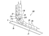
- the screen device includes a right first vertical frame ridge 2a and a left second vertical frame ridge 2b, an upper first horizontal frame ridge 3a, and a lower second horizontal frame ridge 2b.
- a rectangular screen frame 1 made up of a frame rod 3b, and an operation rod 4 arranged vertically in the screen frame 1 is supported at the upper end by the first horizontal frame rod 3a, and The lower end is disposed so as to be movable in the left-right direction while being supported by the support rail 5 on the upper surface of the second horizontal frame rod 3b.
- a take-up shaft 7 is disposed so as to be rotatable about a vertical axis,
- the base end portion of the screen 8 is wound around the shaft 7, and the front end portion of the screen 8 is directed to the inside of the screen frame 1 from the slit-shaped opening 2 c formed on the inner surface of the first vertical frame rod 2 a.
- And is connected to the operation rod 4. Therefore, it can be said that the screen 8 is stretched between the first vertical frame rod 2 a and the operation rod 4.
- the operation rod 4 has a rectangular cross-sectional shape that is elongated to the left and right, and the screen attachment portion 4 b on the first vertical frame rod 2 a side and the second vertical frame.
- a slit-like connecting groove 9 is formed in the vertical direction on the inner surface of the screen mounting portion 4b facing the first vertical frame ridge 2a, and the connecting groove 9 is formed at the tip of the screen 8.
- the attached connecting member 10 is inserted, and the locking body 10a at the tip of the connecting member 10 is locked to the inner edge of the connecting groove 9, whereby the tip of the screen 8 is connected to the operation rod 4. Yes.
- the connecting member 10 is formed by fixing the locking body 10a having a plurality of protrusions to an end portion of a tape-like base material 10b. It is attached to the part by methods such as welding and sewing.
- the winding shaft 7 winds up the screen 8 by using the elastic force of the coil spring 7a incorporated therein as a winding force.
- the operating rod 4 is moved to the left in FIG. 1 to move the screen 8 to the winding shaft.
- the coil spring 7a is pulled out, the coil spring 7a is twisted to accumulate the winding force.
- the operating rod 4 is moved to the right in FIG. 1 to open the screen frame 1, the coil spring 7a accumulates.
- the screen 8 is wound up by the wound winding force.
- a member denoted by reference numeral 11 in the drawing is a handle for opening and closing the operation rod 4.
- the screen device has a function of preventing the tilting of the operation rod 4 during the opening / closing operation, and a function of preventing the lower end portion of the screen 8 from being bent or displaced due to an action of wind or the like.
- a screen support mechanism 14 is also provided.
- the screen support mechanism 14 includes a screen guide 15 that supports the lower end portion of the screen 8 straight and the support rail 5 that supports the screen guide 15 along the screen 8 in a straight line.
- the support rail 5 has a first locking edge 5a and a second locking edge 5b in the form of flanges protruding on both sides in the width direction of the support rail 5.
- the front surface 16a is inclined in a direction in which the thickness of the locking edge gradually decreases toward the distal end side of each locking edge 5a, 5b.
- the back surface 16b forms a horizontal plane.
- the screen guide 15 is formed by connecting a plurality of synthetic resin guide pieces 17 so that they can be bent in series and only in one direction.
- one end 15a of the screen guide 15 is fixed to the lower end portion of the first vertical frame rod 2a, and the other end 15b extends from the opening 4a at the lower end of the operation rod 4 to the screen guide accommodating portion 4c.
- the other end 18b of the attachment wire 18 is led out from the upper end of the operation rod 4 into the first horizontal frame rod 3a to be connected to the one end 18a of the attachment wire 18. It is fixed to the frame rod 3a.
- the guide piece 17 has an upper piece main body 20 that engages with the lower end of the screen 8 and a concave support groove 22 into which the support rail 5 is fitted on the lower surface. It is formed by connecting the lower locking member 21 provided so as to be relatively rotatable in the forward and reverse directions around a vertical axis L passing through the center of the guide piece 17.
- the plan view shape of the guide piece 17 is a rectangle having a larger diameter Y in the left-right direction (indoor / outdoor direction) than the diameter X in the front-rear direction (connection direction). Note that “front and rear” and “left and right” of the guide piece 17 are directions when the guide piece 17 is viewed from the front side at one end in the connecting direction, as shown in FIG.
- the piece body 20 has a pair of wire insertion holes 24, 24 at a position near the upper end in the height direction and near both ends in the left-right direction. As shown in FIGS. 5 and 6, a plurality of wires 25 having flexibility are inserted through the wire insertion holes 24, 24 so as to penetrate from the end E 1 side to the opposite second end E 2 side.
- the screen guides 15 are formed by connecting the guide pieces 17 in series. By connecting the plurality of guide pieces 17 in such a manner, the screen guide 15 can be bent only in the direction in which the upper surface side becomes the concave side.
- a slit-like engagement groove 27 in which an engagement member 26 (see FIGS. 1 and 4) at the lower end of the screen 8 is fitted and engaged with a central portion of the upper surface of the piece body 20 in the left-right direction. Is formed so as to penetrate the piece body 20 from the first end E1 side to the second end E2 side, and the inner end of the engagement groove 27 has an enlarged portion 27a wider than the engagement groove 27. It has become.
- the engaging member 26 is formed by fixing a plurality of protruding engaging members 26a to the end of a tape-like base material 26b. 26b is attached to the lower end of the screen 8 by a method such as welding or sewing.
- the engaging member 26 is inserted into the engaging groove 27 of the piece body 20 pulled out.
- the screen 8 and the guide piece 17 are sequentially engaged with each other when the engaging body 26a is engaged with the inner edge of the engaging groove 27 in the enlarged portion 27a.
- the engagement member 26 is disengaged from the engagement groove 27 of the piece body 20 to be pulled.
- the locking member 21 is a member having a planar view shape that is substantially the same size and the same size as the planar view shape of the piece main body 20, and is connected to the lower surface of the piece main body 20 by the connecting mechanism 30. Is connected so as to be rotatable between a first position A (FIG. 9A) and a second position B (FIG. 9B). A groove 22 is formed.
- the support groove 22 is formed when the locking member 21 is not rotated with respect to the piece body 20, that is, when the locking member 21 is in the first position A.
- the guide piece 17 is inclined obliquely with respect to the virtual plane S that is divided into two in the left-right direction, and when the locking member 21 is rotated with respect to the piece body 20, that is, the locking piece When the member 21 is in the second position B, it is formed so as to be parallel to the virtual plane S.
- the support groove 22 faces obliquely with respect to the support rail 5 at the first position A, and at the second position B. It can also be said that it is formed so as to be parallel to the support rail 5.
- the axis L is located in the virtual plane S.
- the locking member 21 when the locking member 21 is in the first position A, it faces the same direction as the piece main body 20 and thus exactly overlaps with the piece main body 20, but when rotated to the second position B, In order to face in a direction different from the piece main body 20, the opposite corners 21 a and 21 b of the locking member 21 protrude from the end surfaces 20 a and 20 b of the piece main body 20, respectively.
- the groove width W1 of the support groove 22 is slightly larger than the lateral width (front-rear direction width) W2 of the support rail 5, when the locking member 21 is in the first position A, the support width Of the pair of opposed groove walls of the groove 22, a part of one first groove wall 22a abuts on the first locking edge 5a of the support rail 5, and a part of the other second groove wall 22b is Then, it comes into contact with the second locking edge 5b of the support rail 5. Therefore, locking portions 31a and 31b that are locked to the locking edges 5a and 5b are formed at the respective contact portions.
- a first locking portion 31a is formed at a portion where the first groove wall 22a contacts the first locking edge 5a, and a portion where the second groove wall 22b contacts the second locking edge 5b.
- a second locking portion 31b is formed.
- the first locking portion 31 a is formed on the first end E 1 side of the guide piece 17, and the second locking portion 31 b is formed on the second end E 2 side of the guide piece 17.
- the first locking portion 31 a and the second locking portion 31 b have a locking claw 32 that protrudes inward in the width direction of the support groove 22.
- the inner surface 32a facing the groove bottom side 22c and the outer surface 32b on the opposite side thereof are inclined surfaces that gradually incline toward the distal end side of the locking claw 32 in a direction in which the thickness of the locking claw 32 gradually decreases. ing.
- connection mechanism 30 that connects the piece body 20 and the locking member 21 includes a groove-like connection recess 35 formed on the bottom surface of the piece body 20, and the engagement mechanism 30. It has the connection convex part 36 which is formed in the upper surface of the stop member 21, and fits into the said connection recessed part 35. As shown in FIG.
- the connecting recess 35 is formed between a pair of opposing recess side walls 37 a and 37 b, and a bearing portion 38 is provided at the center of the connecting recess 35.
- one first concave side wall 37a is inclined from the second end E2 side of the piece main body 20 toward the virtual plane S while being gradually closer to the first end E1.
- a first inclined portion 39a extending linearly to the first inclined portion 39a
- a second inclined portion 39b extending from the tip end portion of the first inclined portion 39a to the second end E2, and the first inclined portion 39a and the second inclined portion 39b.
- the other second recess side wall 37b is formed so as to be symmetrical with the first recess side wall 37a with respect to the axis L.
- the bearing portion 38 has a cylindrical shape, and has a bearing hole 40 at a position on the axis L passing through the center thereof, and the first end E1 side and the second side of the piece body 20 from the side surface of the column. Two positioning protrusions 41 and 41 projecting toward the end E2 side are provided.
- the connecting convex portion 36 of the locking member 21 is formed with a first convex side wall 42a and a second convex side wall 42b that are in contact with the first concave side wall 37a and the second concave side wall 37b.
- the first convex portion side wall 42a and the second convex portion side wall 42b are provided with a first inclined portion 43a, a second inclined portion 43b, and a connecting portion corresponding to the first inclined portion 39a, the second inclined portion 39b, and the connecting portion 39c, respectively.
- 43c, and the connecting portion 43c is formed in an arc shape.
- a shaft 46 is formed, and two positioning holes in which the two positioning projections 41 and 41 are rotatably fitted at positions facing each other via the connecting shaft 46 on the side wall of the bearing fitting portion 45. 47, 47 are formed.
- the positioning protrusion 41 When the locking member 21 rotates about the connecting shaft 46 (axis L) with respect to the piece body 20, the positioning protrusion 41 is displaced inside the positioning hole 47, and the positioning protrusion 41 Is in contact with one of the left and right hole walls of the positioning hole 47, the locking member 21 occupies the first position A, and when the locking member 21 is in contact with the other of the left and right hole walls, It occupies the second position B.
- FIG. 1 shows an intermediate open state in which the operation rod 4 is located in the middle of the opening / closing operation.
- the screen 8 is wound around the winding shaft 7 and the screen guide 15 is pulled into the operating rod 4.
- the screen frame 1 is opened, and conversely, when the operating rod 4 is moved in the left direction (closed direction) in the figure, the screen 8 is pulled out from the winding shaft 7, and the screen guide 15 is The screen frame 1 is closed by being pulled out from the inside of the bag 4 along the lower end portion of the screen 8.
- the guide rod 17 that is locked to the support rail 5 in a horizontal posture is positioned closest to the operation rod 4.
- the guide piece 17 pulled out from the inside of the operation rod 4 onto the support rail 5 gradually moves from a vertical posture to a horizontal posture along the support rail 5 through a bent posture. While changing the direction, the support rail 5 is locked. The operation of the guide piece 17 at that time will be described below.
- FIGS. 12 to 14 illustrate the operation when the guide piece 17 is detached from the support rail 5.
- the locking member 21 of the guide piece 17 is provided.
- the guide When an upward force F acts on the piece 17, as shown in FIGS. 13A and 13B, the inner surfaces 32a of the locking claws 32 of the first locking portion 31a and the second locking portion 31b It contacts the back surface 16b of the first locking edge 5a and the second locking edge 5b.
- the locking claw 32 is disposed along the inner surface 32a between the locking claw 32 and the locking edges 5a, 5b.
- a force to be displaced toward the tip end of 5b acts, and this force generates a moment about the axis L in the locking member 21, and the moment causes the locking member 21 to rotate in the direction of arrow M. .
- the locking claw 32 is displaced in a direction away from the locking edges 5a and 5b, as shown in FIG.
- the locking claw 32 Since the locking member 21 continues to rotate, the locking claw 32 is displaced to a position completely disengaged from the locking edges 5a and 5b as shown in FIGS. 14 (a) and 14 (b). Thus, the locking member 21 occupies the second position B, and the support groove 22 faces substantially parallel to the support rail 5. The guide piece 17 is lifted by the upward force F and separated from the support rail 5.
- the guide piece 17 that is removed from the support rail 5 and drawn into the operation rod 4 gradually changes its direction from the bent state to the vertical direction, and finally becomes a state of being linearly connected vertically.
- the locking member 21 of the guide piece 17 occupies the second position B when the guide piece 17 is still in the bent posture, and its corners 21a and 21b are at the first end E1 of the guide piece 17.
- the protruding portion protrudes toward the second end E2 and is pushed against the preceding guide piece 17, so that the locking member 21 returns to the first position A, and each guide is in this state.
- the pieces 17 are connected in a straight line.
- FIGS. 15 to 18 illustrate the operation when the guide piece 17 is locked to the support rail 5.
- a downward force F acts on the guide piece 17 in a state where the locking member 21 of the guide piece 17 is at the first position A, the locking member 21.
- the outer surfaces 32b of the locking claws 32 of the first locking portion 31a and the second locking portion 31b are in contact with the surfaces 16a of the first locking edge 5a and the second locking edge 5b of the support groove 22.
- the outer surface 32b is inclined, as shown in FIGS. 16 (a) and 16 (b), the locking claw is provided between the locking claw 32 and the locking edges 5a and 5b.
- a force acts to displace 32 toward the distal end side of the locking edges 5a and 5b along the outer surface 32b, and a moment about the axis L is generated in the locking member 21 by this force. Since the locking member 21 rotates in the direction of arrow M, the locking claw 32 is displaced in a direction away from the locking edges 5a and 5b.
- the locking claw 32 is displaced to a position completely disengaged from the locking edges 5a and 5b, and then the guide piece 17 is moved to the position shown in FIG. As shown in (b), the support rail 5 is displaced to a position where the support rail 5 is fitted. At this time, the locking member 21 is in the second position B, and the support groove 22 is substantially parallel to the support rail 5. Further, the corners 21a and 21b of the locking member 21 protrude outward on the first end E1 side and the second end E2 side of the guide piece 17.
- the guide piece 17 continues linearly after the preceding guide piece 17 along the support rail 5 (see FIG. 4 to FIG. 7). At this time, the first end of the locking member 21 is connected. Since the corner portion 21a protruding to the E1 side is pressed against the end surface on the second end E2 side of the preceding guide piece 17, the locking member 21 rotates and returns to the first position A. Thereby, as shown in FIGS. 18A and 18B, the guide piece 17 has the first locking portion 31a of the locking member 21 and the locking claw 32 of the second locking portion 31b connected to the support rail. 5 is locked to the first locking edge 5a and the second locking edge 5b.
- the downward force F first acts on the first end E 1 side of the guide piece 17, so that the guide piece 17 is applied to the support rail 5.
- the operation of locking is performed mainly by the first end E1 side.
- the guide pieces 17 connected in a line along the support rail 5 are arranged so that the front and rear guide pieces 17 and 17 are brought into close contact with each other, so that the locking member 21 is restrained to the first position A. Even if an upward force is applied to the guide piece 17 through the screen 8, the locking member 21 cannot be rotated toward the second position B, so that the guide piece 17 is detached from the support rail 5. There is nothing. In this way, the guide piece 17 of the screen guide 15 is engaged with or detached from the support rail 5 at an intermediate position of the support rail 5.
- FIG. 19 shows a first modification of the screen guide.
- a plurality of guide pieces 17A are sequentially connected by pins. That is, on the end face of the guide piece 17A on the first end E1 side of the piece main body 20, a pair of connecting arms 50 and 50 project in the longitudinal direction of the screen guide 15A at the front and rear opposing positions.
- the connection pins 51 are attached to the pair of connection arms 50 and 50, respectively, and the end surface on the second end E2 side of the piece body 20 is at a position opposite to the front and rear of the upper end portion thereof.
- a pair of arm receivers 52, 52 having a concave step shape are formed, and pin holes 53 are formed in the arm receivers 52, 52, respectively.
- the screen guide 15A is formed by sequentially connecting adjacent guide pieces 17A and 17A to each other by the connecting pin 51 and the pin hole 53.
- FIGS. 20 to 22 show a second modification of the screen guide.
- the guide piece 17B constituting the screen guide 15B of the second modification has a locking member 21 which is the screen guide 15 of the basic form. This is different from the configuration of the locking member 21 of the guide piece 17 in FIG.
- the locking member 21 of the guide piece 17 ⁇ / b> B has a pair of sliding pieces 21 ⁇ / b> A and 21 ⁇ / b> B that can be displaced obliquely with respect to the support rail 5 and in opposite directions.
- the pair of sliding part pieces 21 ⁇ / b> A and 21 ⁇ / b> B has a shape in which the rectangular locking member 21 is divided into two along the sliding contact surface 56 intersecting with the virtual surface S, and the bottom surface of the piece body 20.
- a support groove 22 is formed between the pair of sliding part pieces 21A and 21B, and a first locking part 31a is formed on one first sliding part piece 21A, and the other second sliding part.
- a second locking portion 31b is formed on the piece 21B.
- An angle ⁇ 1 formed by the sliding contact surface 56 with the virtual surface S is larger than an angle ⁇ 2 formed by the support groove 22 with the virtual surface S. Further, a rotation prevention mechanism (not shown) is provided so that the pair of sliding pieces 21 ⁇ / b> A and 21 ⁇ / b> B does not rotate around the sliding pin 58.
- the guide piece 17B other than the above-described configuration is substantially the same as that of the guide piece 17 of the screen guide 15 of the basic form
- the guide of the screen guide 15 of the basic form is included in the same same component part.
- the same reference numerals as those used for the piece 17 are attached, and the description thereof is omitted.
- the locking member 21 occupies the first position A
- the locking claw 32 of the first locking part 31a in the first sliding part piece 21A and the locking claw 32 of the second locking part 31b in the second sliding part piece 21B are the first of the support rail 5. It is locked to the locking edge 5a and the second locking edge 5b, respectively.
- the pair of sliding pieces 21A and 21B of the locking member 21 at the first position A are After being displaced once to the second position B of FIG. 22 by the interaction between the locking claw 32 and the locking edges 5a and 5b of the support rail 5, the support rail 5 is fitted into the support groove 22 and then adjacent to the front and rear.
- the sliding member returns to the first position A in FIG. 21, and as a result, the guide piece 17 moves to the support rail 5. Will be locked.
- the pair of sliding pieces 21A and 21B may be configured to be displaced straight in the force N1 direction (left and right direction), or may be configured to open and close to the left and right like a clip. it can.
- the locking claw can be provided not at the end portion of the sliding piece 21A, 21B but at the central portion or over the entire portion.
- locking part 31b in the guide piece 17 are inclined surfaces
- the surface 16a is made into the inclined surface and the back surface 16b is made into the horizontal surface, it is not restricted to such a case
- the said locking claw 32 and the said In the inner surface 32a and the back surface 16b that are engaged with the locking edges 5a and 5b at least one of the surfaces may be an inclined surface.
- the outer surface 32b and the surface 16a also include at least One surface may be an inclined surface.
- the screen guide 15 is disposed only on the lower end side of the screen 8, but the screen guide 15 may be disposed on the upper end side of the screen 8, It can also be arranged on both lower ends.
- the present invention is not limited to a winding screen device using a flat screen as shown in the above embodiment, but also an accordion-type screen that can be bent and stretched as disclosed in Patent Document 2, for example.
- the present invention can be similarly applied to a screen apparatus using a screen having a honeycomb-shaped cross-sectional structure. In this case, the screen and the guide piece of the screen guide are engaged with each other with the end of the screen fitted in the groove of the guide piece. In some cases, the engagement is not coupled to each other.
Landscapes
- Engineering & Computer Science (AREA)
- Structural Engineering (AREA)
- Architecture (AREA)
- Civil Engineering (AREA)
- Life Sciences & Earth Sciences (AREA)
- Insects & Arthropods (AREA)
- Pest Control & Pesticides (AREA)
- Operating, Guiding And Securing Of Roll- Type Closing Members (AREA)
Abstract
[Problème] La présente invention a pour objet de mettre en œuvre un dispositif d'écran configuré de telle sorte qu'un dispositif de guidage d'écran peut être mis en prise avec un rail de support et séparé de celui-ci au niveau de la position intermédiaire du rail de support. [Solution] La présente invention concerne un rail de support 5 servant à supporter un dispositif de guidage d'écran 15, ayant un premier bord de mise en prise 5a et un deuxième bord de mise en prise 5b. Le dispositif de guidage d'écran 15 est formé par le raccordement en série d'une pluralité d'éléments de guidage 17. Les éléments de guidage 17 comportent chacun : un corps d'élément 20 se mettant en prise avec une extrémité d'un écran ; et un élément de mise en prise 21 comportant une première section de mise en prise 31a et une deuxième section de mise en prise 31b, qui se mettent en prise avec le premier bord de mise en prise 5a et le deuxième bord de mise en prise 5b du rail de support 15. Chacun des éléments de mise en prise 21 est raccordé à un corps respectif parmi les corps d'élément 20 de telle sorte que l'élément de mise en prise 21 peut être déplacé vers une première position A dans laquelle la première section de mise en prise 31a et la deuxième section de mise en prise 31b se mettent en prise avec le premier bord de mise en prise 5a et le deuxième bord de mise en prise 5b du rail de support 5, et peut également être déplacé vers une deuxième position B où la première section de mise en prise 31a et la deuxième section de mise en prise 31b sont séparées du premier bord de mise en prise 5a et du deuxième bord de mise en prise 5b.
Priority Applications (3)
| Application Number | Priority Date | Filing Date | Title |
|---|---|---|---|
| ES17770090T ES2879883T3 (es) | 2016-03-24 | 2017-03-16 | Dispositivo de pantalla |
| EP17770090.3A EP3453824B1 (fr) | 2016-03-24 | 2017-03-16 | Dispositif d'écran |
| US16/085,824 US11384598B2 (en) | 2016-03-24 | 2017-03-16 | Screen device |
Applications Claiming Priority (2)
| Application Number | Priority Date | Filing Date | Title |
|---|---|---|---|
| JP2016-060448 | 2016-03-24 | ||
| JP2016060448A JP6612162B2 (ja) | 2016-03-24 | 2016-03-24 | スクリーン装置 |
Publications (1)
| Publication Number | Publication Date |
|---|---|
| WO2017164047A1 true WO2017164047A1 (fr) | 2017-09-28 |
Family
ID=59900351
Family Applications (1)
| Application Number | Title | Priority Date | Filing Date |
|---|---|---|---|
| PCT/JP2017/010558 WO2017164047A1 (fr) | 2016-03-24 | 2017-03-16 | Dispositif d'écran |
Country Status (6)
| Country | Link |
|---|---|
| US (1) | US11384598B2 (fr) |
| EP (1) | EP3453824B1 (fr) |
| JP (1) | JP6612162B2 (fr) |
| ES (1) | ES2879883T3 (fr) |
| TW (1) | TWI715744B (fr) |
| WO (1) | WO2017164047A1 (fr) |
Cited By (2)
| Publication number | Priority date | Publication date | Assignee | Title |
|---|---|---|---|---|
| EP3527774A1 (fr) * | 2018-02-19 | 2019-08-21 | Primed S.r.l. | Rideau facile a monter et methode relative pour monter |
| IT201900001161A1 (it) * | 2019-01-25 | 2020-07-25 | Primed S R L | Dispositivo di schematura a montaggio facilitato e relativo metodo di installazione |
Families Citing this family (6)
| Publication number | Priority date | Publication date | Assignee | Title |
|---|---|---|---|---|
| TWI708886B (zh) * | 2016-03-30 | 2020-11-01 | 日商世紀販賣股份有限公司 | 捲軸屏幕裝置 |
| JP6998584B2 (ja) * | 2017-10-04 | 2022-01-18 | セイキ住工株式会社 | 横引きロールスクリーン装置 |
| CN110359835B (zh) * | 2019-08-02 | 2021-04-30 | 张兆国 | 一种利用推力来对纱窗进行清洁的隐形纱窗 |
| TWI768537B (zh) * | 2020-11-06 | 2022-06-21 | 清展科技股份有限公司 | 具有遮擋裝置之屏幕及其遮擋裝置 |
| CN112412318A (zh) * | 2020-11-09 | 2021-02-26 | 清展科技股份有限公司 | 具有遮挡装置之屏幕及其遮挡装置 |
| US11505991B2 (en) * | 2021-03-24 | 2022-11-22 | Metaco Inc. | Screen device |
Citations (3)
| Publication number | Priority date | Publication date | Assignee | Title |
|---|---|---|---|---|
| JP2004346578A (ja) * | 2003-05-21 | 2004-12-09 | Seiki Hanbai Co Ltd | 巻取り式スクリーン装置 |
| JP2005023578A (ja) * | 2003-06-30 | 2005-01-27 | Seiki Hanbai Co Ltd | 可収納張設面部材の端部ガイド |
| JP2015172316A (ja) * | 2014-03-12 | 2015-10-01 | セイキ販売株式会社 | スクリーン装置 |
Family Cites Families (9)
| Publication number | Priority date | Publication date | Assignee | Title |
|---|---|---|---|---|
| JP3965334B2 (ja) * | 2001-10-30 | 2007-08-29 | セイキ住工株式会社 | 横引き網戸 |
| ES2401841T3 (es) * | 2003-06-30 | 2013-04-24 | Seiki Hanbai Co., Ltd. | Dispositivo de cortina |
| EP1688582B1 (fr) * | 2003-10-21 | 2014-01-22 | Seiki Hanbai Co., Ltd. | Porte-ecran coulissante |
| JP4850498B2 (ja) * | 2005-11-30 | 2012-01-11 | セイキ販売株式会社 | 折畳式スクリーン装置 |
| US7810543B2 (en) * | 2007-12-11 | 2010-10-12 | Effe S.R.L. | Roller screen device |
| NZ584412A (en) * | 2009-04-02 | 2011-10-28 | Chris Bonython | Screen for a door or window that is wider than it is tall |
| JP5284239B2 (ja) * | 2009-10-07 | 2013-09-11 | 株式会社メタコ | スクリーン装置 |
| AR088833A1 (es) * | 2012-11-09 | 2014-07-10 | Luisa Grun Andrea | Dispositivo con red de proteccion para aberturas que incluye uñas de engarce montadas en perfil con pestañas para sujecion de la red |
| WO2016015084A1 (fr) * | 2014-07-28 | 2016-02-04 | Screenaway Pty Ltd | Système de moustiquaire rétractable pouvant faire l'objet d'un rétromontage |
-
2016
- 2016-03-24 JP JP2016060448A patent/JP6612162B2/ja active Active
-
2017
- 2017-03-16 ES ES17770090T patent/ES2879883T3/es active Active
- 2017-03-16 EP EP17770090.3A patent/EP3453824B1/fr active Active
- 2017-03-16 US US16/085,824 patent/US11384598B2/en active Active
- 2017-03-16 WO PCT/JP2017/010558 patent/WO2017164047A1/fr active Application Filing
- 2017-03-23 TW TW106108363A patent/TWI715744B/zh active
Patent Citations (3)
| Publication number | Priority date | Publication date | Assignee | Title |
|---|---|---|---|---|
| JP2004346578A (ja) * | 2003-05-21 | 2004-12-09 | Seiki Hanbai Co Ltd | 巻取り式スクリーン装置 |
| JP2005023578A (ja) * | 2003-06-30 | 2005-01-27 | Seiki Hanbai Co Ltd | 可収納張設面部材の端部ガイド |
| JP2015172316A (ja) * | 2014-03-12 | 2015-10-01 | セイキ販売株式会社 | スクリーン装置 |
Cited By (2)
| Publication number | Priority date | Publication date | Assignee | Title |
|---|---|---|---|---|
| EP3527774A1 (fr) * | 2018-02-19 | 2019-08-21 | Primed S.r.l. | Rideau facile a monter et methode relative pour monter |
| IT201900001161A1 (it) * | 2019-01-25 | 2020-07-25 | Primed S R L | Dispositivo di schematura a montaggio facilitato e relativo metodo di installazione |
Also Published As
| Publication number | Publication date |
|---|---|
| US20190048659A1 (en) | 2019-02-14 |
| EP3453824A4 (fr) | 2019-11-13 |
| JP2017172252A (ja) | 2017-09-28 |
| ES2879883T3 (es) | 2021-11-23 |
| TWI715744B (zh) | 2021-01-11 |
| TW201801651A (zh) | 2018-01-16 |
| JP6612162B2 (ja) | 2019-11-27 |
| US11384598B2 (en) | 2022-07-12 |
| EP3453824B1 (fr) | 2021-05-19 |
| EP3453824A1 (fr) | 2019-03-13 |
Similar Documents
| Publication | Publication Date | Title |
|---|---|---|
| WO2017164047A1 (fr) | Dispositif d'écran | |
| JP6000807B2 (ja) | スクリーン装置のスライドガイド枠部 | |
| JP6031136B2 (ja) | 網戸およびサッシ | |
| KR101930728B1 (ko) | 일체형 방충망 창호 | |
| JP2017179843A (ja) | ロールスクリーン装置 | |
| TWI461595B (zh) | 鎖裝置及拉門框 | |
| JP2007297798A (ja) | シャッタ装置 | |
| JP4084327B2 (ja) | スクリーン装置 | |
| KR102051893B1 (ko) | 블라인드 고정용 브라켓 및 그를 포함하는 블라인드 장치 | |
| JP5385820B2 (ja) | 滑り出し式開口部装置 | |
| KR101163161B1 (ko) | 롤방충망용 개폐장치 및 이를 포함하는 롤방충망 장치 | |
| JP6741604B2 (ja) | スクリーン装置 | |
| JP4954963B2 (ja) | 建具 | |
| JP6468930B2 (ja) | ガイドレール及びガイドレールの設置方法 | |
| JP7328886B2 (ja) | ブラインドの操作装置 | |
| JP2007023691A (ja) | シャッターカーテンのガイド構造 | |
| JP6498068B2 (ja) | シャッター収納部の取付構造 | |
| JPH0128236Y2 (fr) | ||
| JP6522315B2 (ja) | サッシ | |
| JP2016223245A (ja) | バリアフリー型横引きロールスクリーン装置 | |
| KR102416134B1 (ko) | 링크 연결식 프로젝트 창문 | |
| JP6747719B2 (ja) | モジュール式スクリーン装置 | |
| JP2007297797A (ja) | シャッタ装置 | |
| KR200461332Y1 (ko) | 롤방충망 장치용 리드프레임 | |
| JP2016186199A (ja) | 網戸付きサッシ |
Legal Events
| Date | Code | Title | Description |
|---|---|---|---|
| NENP | Non-entry into the national phase |
Ref country code: DE |
|
| WWE | Wipo information: entry into national phase |
Ref document number: 2017770090 Country of ref document: EP |
|
| ENP | Entry into the national phase |
Ref document number: 2017770090 Country of ref document: EP Effective date: 20181024 |
|
| 121 | Ep: the epo has been informed by wipo that ep was designated in this application |
Ref document number: 17770090 Country of ref document: EP Kind code of ref document: A1 |